

Page 1

SERVICE MANUAL
MULTIFUNCTIONAL DIGITAL SYSTEMS
e-STUDIO161
MR-2015
MY-1022
File No. SME03003100
R03112148300-TTEC
VerB1_2003-12
Page 2

© 2003 TOSHIBA TEC CORPORATION
All rights reserved
Parts marked with " " are important for maintaining the safely of the machine. Be sure to replace these
parts with the replacement parts specified to maintain the safety and performance of the machine.
This document has been published to be used for after sales service only.
The contents are subject to change without notice.
Page 3
GENERAL PRECAUTIONS REGARDING THE INSTALLATION AND
SERVICE FOR e-STUDIO161
The installation and service should be done by a qualified service technician.
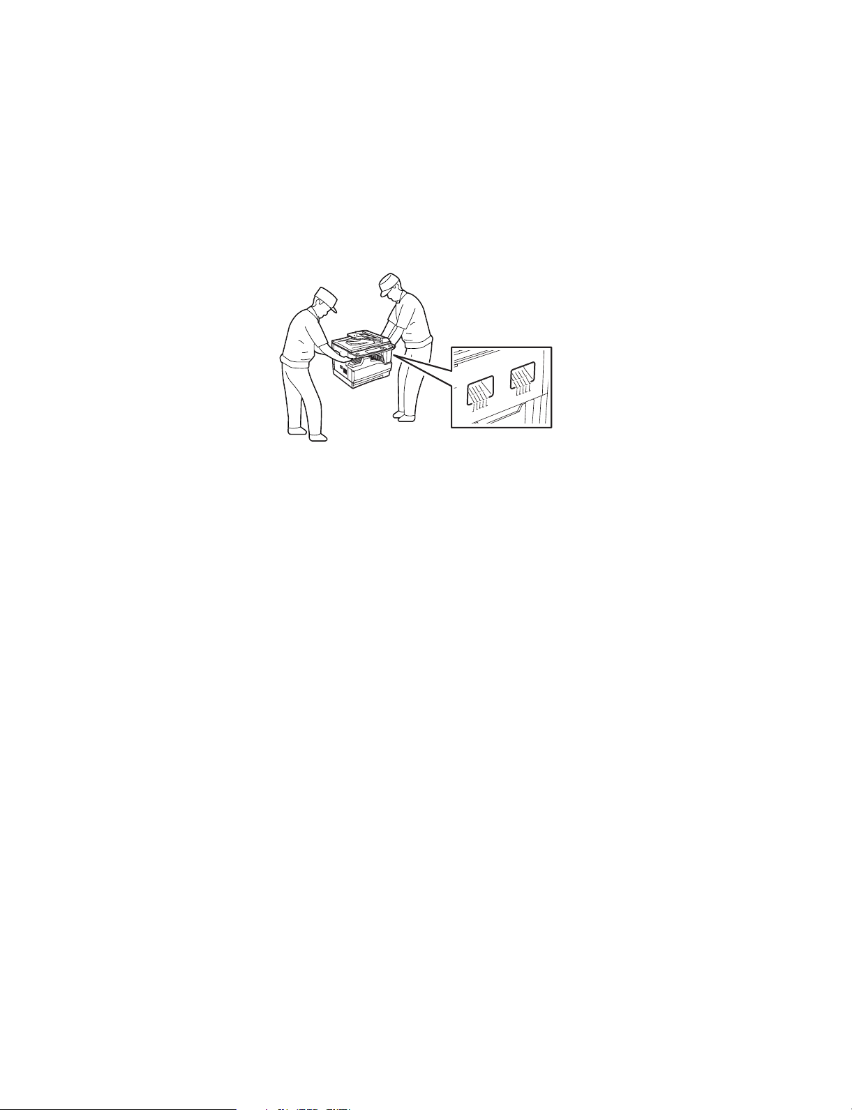
1. Transportation/Installation
• When transporting/installing the machine, employ two persons and be sure to use the positions as
indicated below.
The machine is quite heavy and weighs approximately 30kg (14.3 lb.), therefore pay full attention
when handling it.
• Be sure to use a dedicated outlet with AC 110A, 115V or 127V/10A, 220V-240V or 240V/5A) for its
power source.
• The machine must be grounded for safety.
Never ground it to a gas pipe or a water pipe.
• Select a suitable place for installation.
Avoid excessive heat, high humidity, dust, vibration and direct sunlight.
• Also provide proper ventilation as the machine emits a slight amount of ozone.
• The socket-outlet shall be installed near the machine and shall be easily accessible.
2. Service of Machines
• Basically, be sure to turn the main switch off and unplug the power cord during service.
• Be sure not to touch high-temperature sections such as the exposure lamp, the fuser unit and their
periphery.
• Be sure not to touch high-voltage sections such as the chargers and the high-voltage transformer.
Especially, the board of these components should not be touched since the electric charge may
remain in the capacitors, etc. on them even after the power is turned OFF.
• Be sure not to touch rotating/operating sections such as gears, belts, pulleys, fan, etc.
• Be careful when removing the covers since there might be the parts with very sharp edges underneath.
• When servicing the machines with the main switch turned on, be sure not to touch live sections and
rotating/operating sections. Avoid exposure to laser radiation.
• Use suitable measuring instruments and tools.
• Avoid exposure to laser radiation during servicing.
- Avoid direct exposure to the beam.
- Do not insert tools, parts, etc. that are reflective into the path of the laser beam.
- Remove all watches, rings, bracelets, etc. that are reflective.
• Unplug the power cable and clean the area around the prongs of the plug once a year or more.
A fire may occur when dust lies on this area.
Page 4

3. Main Service Parts for Safety
• The breaker, door switch, fuse, thermostat, thermofuse, thermistor, etc. are particularly important
for safety. Be sure to handle/install them properly. If these parts are shorted circuit and/or made
their functions out, they may burn down, for instance, and may result in fatal accidents. Do not allow
a short circuit to occur. Do not use the parts not recommended by Toshiba TEC Corporation.
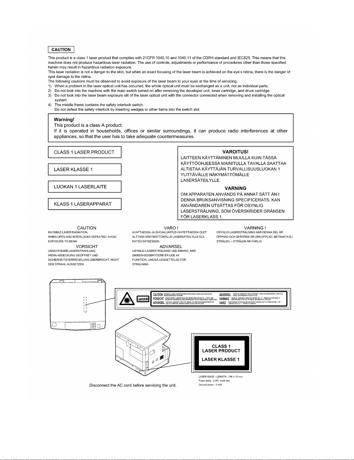
4. Cautionary Labels
• During servicing, be sure to check the rating plate and the cautionary labels such as “Unplug the
power cord during service”, “Hot area”, “Laser warning label” etc. to see if there is any dirt on their
surface and whether they are properly stuck to the machine.
5. Disposition of Consumable Parts, Packing Materials
• Regarding the recovery and disposal of the machine, supplies, consumable parts, packing materials,
follow the relevant local regulations or rules.
6. When parts are disassembled, reassembly is basically the reverse of disassembly unless
otherwise noted in this manual or other related documents. Be careful not to reassemble
small parts such as screws, washers, pins, E-rings, star washers in the wrong places.
7. Basically, the machine should not be operated with any parts removed or disassembled.
8. Precautions Against Static Electricity
• The PC board must be stored in an anti-electrostatic bag and handled carefully using a wristband,
because the ICs on it may become damaged due to static electricity.
Caution: Before using the wristband, pull out the power cord plug of the machine and make
sure that there are no uninsulated charged objects in the vicinity.
Page 5
Page 6

CONTENTS
[1] GENERAL
1. Note for servicing. . . . . . . . . . . . . . . . . . . . . . . . . . . . . .1-1
[2] SPECIFICATIONS
1. Copy mode. . . . . . . . . . . . . . . . . . . . . . . . . . . . . . . . . . .2-1
[3] CONSUMABLE PARTS
1. Supply system table . . . . . . . . . . . . . . . . . . . . . . . . . . . .3-1
2. Environmental conditions . . . . . . . . . . . . . . . . . . . . . . . .3-2
3. Production number identification . . . . . . . . . . . . . . . . . .3-2
[4] EXTERNAL VIEWS AND INTERNAL STRUCTURES
1. Appearance . . . . . . . . . . . . . . . . . . . . . . . . . . . . . . . . . .4-1
2. Internal. . . . . . . . . . . . . . . . . . . . . . . . . . . . . . . . . . . . . .4-1
3. Operation Section . . . . . . . . . . . . . . . . . . . . . . . . . . . . .4-2
4. Motor, solenoid, clutch . . . . . . . . . . . . . . . . . . . . . . . . . .4-3
5. Sensor, switch . . . . . . . . . . . . . . . . . . . . . . . . . . . . . . . .4-4
6. PWB unit . . . . . . . . . . . . . . . . . . . . . . . . . . . . . . . . . . . .4-5
7. Cross sectional view . . . . . . . . . . . . . . . . . . . . . . . . . . .4-6
[5] UNPACKING AND INSTALLATION
1. Installing conditions . . . . . . . . . . . . . . . . . . . . . . . . . . . .5-1
2. Removal of protective material and fixing screw . . . . . .5-1
3. Installing procedure . . . . . . . . . . . . . . . . . . . . . . . . . . . .5-1
4. Removal and storage of fixing screw . . . . . . . . . . . . . . .5-2
5. Changing a tray’s paper size setting . . . . . . . . . . . . . . .5-3
[6] ADJUSTMENTS
1. Adjustment item list . . . . . . . . . . . . . . . . . . . . . . . . . . . .6-1
2. Copier adjustment . . . . . . . . . . . . . . . . . . . . . . . . . . . . .6-1
[7] SIMULATIONS
1. Entering the simulation mode. . . . . . . . . . . . . . . . . . . . .7-1
2. Canceling the simulation mode . . . . . . . . . . . . . . . . . . .7-1
3. List of simulations. . . . . . . . . . . . . . . . . . . . . . . . . . . . . .7-1
4. Contents of simulations . . . . . . . . . . . . . . . . . . . . . . . . .7-2
[8] USER PROGRAMS
1. List of user programs . . . . . . . . . . . . . . . . . . . . . . . . . . 8-1
2. Setting the user programs. . . . . . . . . . . . . . . . . . . . . . . 8-3
3. Toner cartridge life . . . . . . . . . . . . . . . . . . . . . . . . . . . . 8-3
[9] TROUBLE CODE LIST
1. Trouble code list . . . . . . . . . . . . . . . . . . . . . . . . . . . . . . 9-1
2. Details of trouble codes . . . . . . . . . . . . . . . . . . . . . . . . 9-1
[10] MAINTENANCE
1. Maintenance table. . . . . . . . . . . . . . . . . . . . . . . . . . . . . 10-1
2. Maintenance display system. . . . . . . . . . . . . . . . . . . . . 10-2
3. Note for replacement of consumable parts . . . . . . . . . . 10-2
[11] DISASSEMBLY AND ASSEMBLY
1. High voltage section / Duplex transport section . . . . . . 11-1
2. Optical section . . . . . . . . . . . . . . . . . . . . . . . . . . . . . . . 11-2
3. Fusing section. . . . . . . . . . . . . . . . . . . . . . . . . . . . . . . . 11-4
4. Paper exit section . . . . . . . . . . . . . . . . . . . . . . . . . . . . . 11-6
5. MCU . . . . . . . . . . . . . . . . . . . . . . . . . . . . . . . . . . . . . . . 11-8
6. Optical frame unit . . . . . . . . . . . . . . . . . . . . . . . . . . . . . 11-8
7. LSU. . . . . . . . . . . . . . . . . . . . . . . . . . . . . . . . . . . . . . . . 11-9
8. Tray paper feed section / Paper transport section . . . . . 11-9
9. Manual multi paper feed section . . . . . . . . . . . . . . . . . . 11-11
10. Power section . . . . . . . . . . . . . . . . . . . . . . . . . . . . . . . 11-13
11. Developing section . . . . . . . . . . . . . . . . . . . . . . . . . . . 11-14
12. Process section . . . . . . . . . . . . . . . . . . . . . . . . . . . . . 11-15
13. Others. . . . . . . . . . . . . . . . . . . . . . . . . . . . . . . . . . . . . 11-15
[12] FLASH ROM VERSION UP PROCEDURE
1. Preparation . . . . . . . . . . . . . . . . . . . . . . . . . . . . . . . . . . 12-1
2. Download procedure . . . . . . . . . . . . . . . . . . . . . . . . . . . .12-1
3. Installation procedure . . . . . . . . . . . . . . . . . . . . . . . . . . . . 12-2
[13] ELECTRICAL SECTION
1. Block diagram . . . . . . . . . . . . . . . . . . . . . . . . . . . . . . . . 13-1
2. Circuit descriptions . . . . . . . . . . . . . . . . . . . . . . . . . . . . 13-2
3. Actual wiring diagram . . . . . . . . . . . . . . . . . . . . . . . . . . 13-5
[14] OPTION MY-1022 (250 sheets paper feed unit)
[15] OPTION MR-2015 (ADF)
Page 7
[1] GENERAL
1. Note for servicing
Pictogram
The label ( ) in the fusing area of the machine indicates the
following:
: Caution, risk of danger
: Caution, hot surface
•poorly ventilated
A. Warning for servicing
•The fusing area is hot. Exercise care in this area when removing misfed
paper.
•Do not look directly at the light source. Doing so may damage your eyes.
B. Cautions for servicing
•Do not switch the machine rapidly on and off. After turning the machine
off, wait 10 to 15 seconds before turning it back on.
•Machine power must be turned off before installing any supplies.
•Place the machine on a firm, level surface.
•Do not install the machine in a humid or dusty location.
•When the machine is not used for a long time, for example, during
prolonged holidays, turn the power switch off and remove the power
cord from the outlet.
•When moving the machine, be sure to turn the power switch off and
remove the power cord from the outlet.
•Do not cover the machine with a dust cover, cloth or plastic film while the
power is on. Doing so may prevent heat dissipation, damaging the
machine.
•Use of controls or adjustments or performance of procedures other than
those specified herein may result in hazardous laser radiation
exposure.
•The socket-outlet shall be installed near the machine and shall be easily
accessible.
•Be careful when removing the covers since there might be the parts with
very sharp edges underneath.
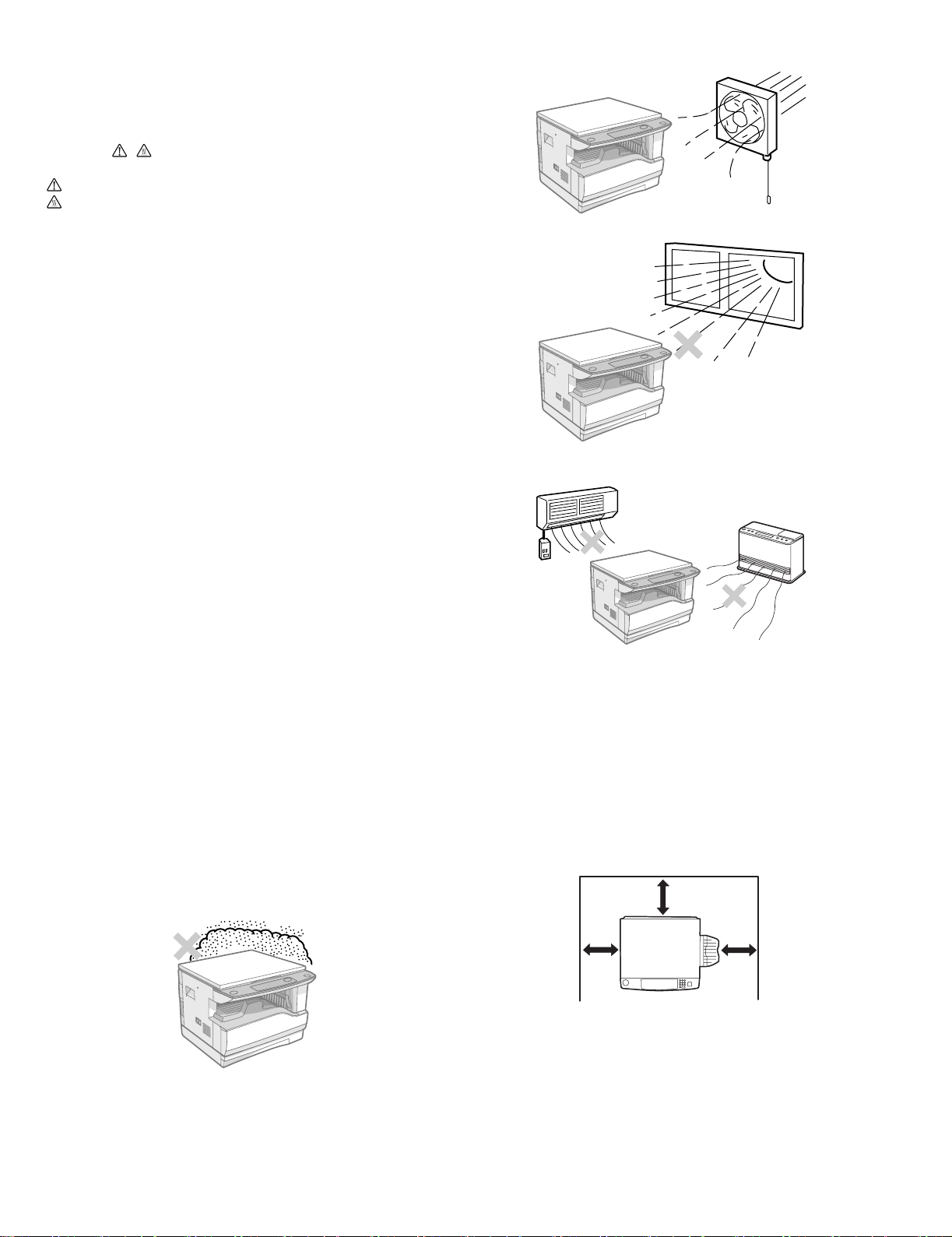
C. Note for installation place
Improper installation may damage the machine. Please note the
following during initial installation and whenever the machine is moved.
Caution : If the machine is moved from a cool place to a warm place,
condensation may form inside the machine. Operation in this
condition will cause poor copy quality and malfunctions. Leave
the machine at room temperature for at least 2 hours before
use.
Do not install your machine in areas that are:
•damp, humid, or very dusty
•exposed to direct sunlight
•subject to extreme temperature or humidity changes, e.g., near an air
conditioner or heater.
The machine should be installed near an accessible power outlet for
easy connection and disconnection.
Be sure to connect the power cord only to a power outlet that meets the
specified voltage and current requirements. Also make certain the outlet
is properly grounded.
Note : Connect the machine to a power outlet which is not used for other
electric appliances. If a lighting fixture is connected to the same
outlet, the light may flicker.
Be sure to allow the required space around the machine for servicing
and proper ventilation.
8" (20 cm)
DP-1620 GENERAL 1-1
8"
(20 cm)
8"
(20 cm)
Page 8
[2] SPECIFICATIONS
1. Copy mode
A. Type
Type Desk-top
Paper exit Wing less
B. Machine composition
DP-1620 16-CPM multi function model
(1) Option
Machine Model
250 sheets paper feed unit MY-1022
ADF MR-2015
C. Copy speed
(1) Scan One Print many
DP-1620 Available
Condition: Copy speed in the normal copy from all the paper feed ports
including the manual paper feed port.
(2) Continuous copy speed (Sheets/min)
Paper size Normal
A3 9 9 9
B4 10 10 10
A4 16 16 16
AB
system
Inch
system
A4R 121212
B5 16 16 16
B5R 141414
LD 9 9 9
LG 10 10 10
8.5" X 13" 11 11 11
LT 16 16 16
LT-R 12 12 12
ST 16 16 16
Enlargement
(200%)
D. First copy time
(1) Basic speed
First copy time 7.2sec (A4, 8.5" X 11"/1st tray/with OC)
(Polygon motor ready state)
Reduction
(50%)
E. Document
Max. document size A3, LD
Document reference
position
Detection (Platen) None
Detection size A3, B4, A4, A4R, B5, B5R, A5
Left side center
LD, LG, 8.5" X 13", LT, ST
(8.5" X 13" is detected by key input.)
(1) ADF
Standard/Option Option : MR-2015
Document load
capacity
Document size
(Max. ~ Min.)
Document
replacement speed
Document set/Paper
feed direction
Document weight 56 ~ 90g/m², 15 ~ 21 lbs
Document size
detection
Document mixture Not Available
40 sheets (Thickness 4mm or less)
A3 ~ A5
LD ~ LT
16 sheets/min
(A4 , 8.5" x 11" normal copy)
Face up, Center reference,
Paper feed from the top
On the document feed tray
F. Pa pe r f ee d
Copy size
(Max. ~ Min.)
Paper feed system 1 cassette + Multi manual paper feed
Paper feed capacity 250 x 1 (Paper feed tray)
Remaining quantity
detection
(1) Paper feed section of the copier
Paper feed
size
Side front Front
Paper feed
capacity
Weight 56 ~ 90g/m² (15 lbs. ~ 21 lbs.)
Special paper Recycled paper
(2) Manual paper feed section
Paper feed
size
Paper feed
capacity
Detection Size detection not available
Weight 56 ~ 200g/m² (15 ~ 34 lbs.)
Special paper Recycled paper, OHP film, labels
Paper feed Single except for recycled paper
A3 ~ A5, Post card
LD ~ LT
+ 100 (Multi bypass feed tray)
Cassette
section
Manual tray Only empty detection available
A3, B4, A4, A4R, B5, B5R, A5, 16K, 16KR, 8K
LD, LG, 8.5" x 13", LT, ST,
(For A5 and LT, only No. 1 tray available.)
250 sheets
(56 ~ 90g/m² equivalent) (15 ~ 21 lbs.)
A3 ~ A6, Post card, LD ~ LT
100 sheets(56 ~ 80g/m²)
Only empty detection available
DP-1620 SPECIFICATIONS 2-1
Page 9
(3) Option paper feed unit
1-step paper feed unit
Model MY-1022
Paper feed size A3, B4, A4, A4R, B5, B5R
Capacity
(56 ~ 80gm²)
Paper weight 56 ~ 90 g/m² (15 ~ 21 lbs.)
Moisture preserving
heater
Paper empty detection Available
Paper size setting User setting
External dimensions
(W x D x H)
Weight About 4.7kg
Special paper Recycled paper
Power Supplied from the machine
Condition:With SPF/RSPF A4/Letter Normal 1cassette
LD, LG, 8.5" x 13", LT, ST
About 250 sheets x
1 step
None
Paper size detection:None
590 x 471 x 88mm
G. Multi copy
Max. number of multi copy 999 sheets
H. Warm-up time
Warm-up time 45 sec
Pre-heat Available
Jam recovery Within 45 sec
I. Copy magnification ratio
Fixed
magnification
ratio
Zooming 25 ~ 400%
Independent
zooming(vertical)
Independent zooming
(horizontal)
AB system:
50, 71, 82, 86, 100, 115, 122, 141, 200%
Inch system:
50, 65, 78, 95, 100, 121, 129, 141, 200%
ADF(50 ~ 200%)
Available (25 ~ 400%)
ADF(50 ~ 200%)
Available (25 ~ 400%)
ADF(50 ~ 200%)
J. Print density
Density mode Auto / Text / Photo
No. of manual
adjustment
Resolution Writing: 600 x 600dpi
Gradation Reading: 256 gradations
Toner save mode Set by the user program
5 steps (Text / Photo)
Reading: 600 (main) x 600 (sub) (PHOTO mode)
600 (main) x 300 (sub) (AE mode)
Writing: Binary
K. Void width
Void area Lead edge 1 ~ 4mm,
Image loss 4mm or less
rear edge 4mm or less,
both sides 4mm or less
L. Paper exit / finishing
Paper exit section capacity Face down 250 sheets
Full detection None
Finishing None
M. Additional functions
APS O
AMS O
Auto tray switching O
Memory copy O
Independent
zooming
1 set 2 copy O Enlargement invalid/ADF invalid
Black/white
reverse
Preheating O The conditions are set by the user
Auto shut-off O The conditions are set by the user
User programming O
Total counter O Supports Total counter, Scan counter, and
Coin vendor
support
Auditor support X
Toner save O
Department
management
O : Available X : Not available
O
(Patent rotation)
X
program.
program.
Copy counter.
X
O (Copy: 20 Dept.)
N. Other specifications
Photoconductor type OPC (Organic Photo Conductor)
Photoconductor drum dia. 30mm
Copy lamp Cold cathode fluorescent lamp (CCFL)
Developing system Dry 2-component magnetic brush
development
Charging system Saw teeth charging
Transfer system (+) DC corotron
Separation system (-) DC corotron
Fusing system Heat roller
Process speed 88mm/s
O. Package form
Body Body / Accessories
P. External view
External dimensions
(W x D x H)
Occupying area
(W x D)
Weight About 31.3kg
590 x 577 x 470 mm
590 x 531mm
(When the manual tray is installed.)
Q. Power source
Voltage AC100V, 110V, 120V, 127V, 230(240)V
Frequency 50/60Hz common
R. Power consumption
Max. power consumption 1200W
* EnergyStar conformity
Average power consumption in
operation
Power consumption when
standby
Energy consumption efficiency Less than 25W
Less than 550W
5W(Not include option)
DP-1620 SPECIFICATIONS 2-2
Page 10

S. Digital performance
Resolution Reading 600 x 600dpi (PHOTO mode)
Writing 600 x 600dpi
Gradation Reading 256 gradations
Writing Binary
Memory 16MB
Hard disk None
600 x 300dpi (AE mode)
T. Printing function
Print speed 12ppm
Data resolution 600dpi
First print 7.2sec
Duplex print None
Paper feed system Paper feed tray and Manual paper feed tray
Support OS Windows 95/98/ME/2000/NT4.0/XP
Emulation GDI
Interface IEEE1284(ECP, Compatible)/USB1.1
PnP support Support on Windows 95/98/ME/2000/XP
Software Status monitor
DP-1620 SPECIFICATIONS 2-3
Page 11
[3] CONSUMABLE PARTS
1. Supply system table
A. USA / CANADA / Latin America
NO Name Content Life Product name Remark
1 Toner cartridge(Black) Toner
(Toner: Net Weight 537g)
Vinyl bag
2 Developer Developer
(Developer : Net Weight 400g)
3 Drum kit Drum
Drum fixing plate
B. Europe / East Europe
NO Name Content Life Product name Remark
1 Toner cartridge(Black) Toner
(Toner: Net Weight 537g)
Vinyl bag
2 Developer Developer
(Developer : Net Weight 400g)
3 Drum kit Drum
Drum fixing plate
C. Asia / Oceania / Saudi Arabia
NO Name Content Life Product name Remark
1 Toner cartridge(Black) Toner
(Toner: Net Weight 537g)
Vinyl bag
2 Developer Developer
(Developer : Net Weight 400g)
3 Drum kit Drum
Drum fixing plate
x10
160K PS-ZT-1620 Life setting by A4 6% document
x10
x10 500K PS-ZD-1620
x10
500K PS-OD-1620
x10
x10
160K PS-ZT-1620E Life setting by A4 6% document
x10
x10 500K PS-ZD-1620
x10
500K PS-OD-1620
x10
x10
160K PS-ZT-1620D Life setting by A4 6% document
x10
x10 500K PS-ZD-1620
x10
500K PS-OD-1620
x10
DP-1620 CONSUMABLE PARTS 3-1
Page 12
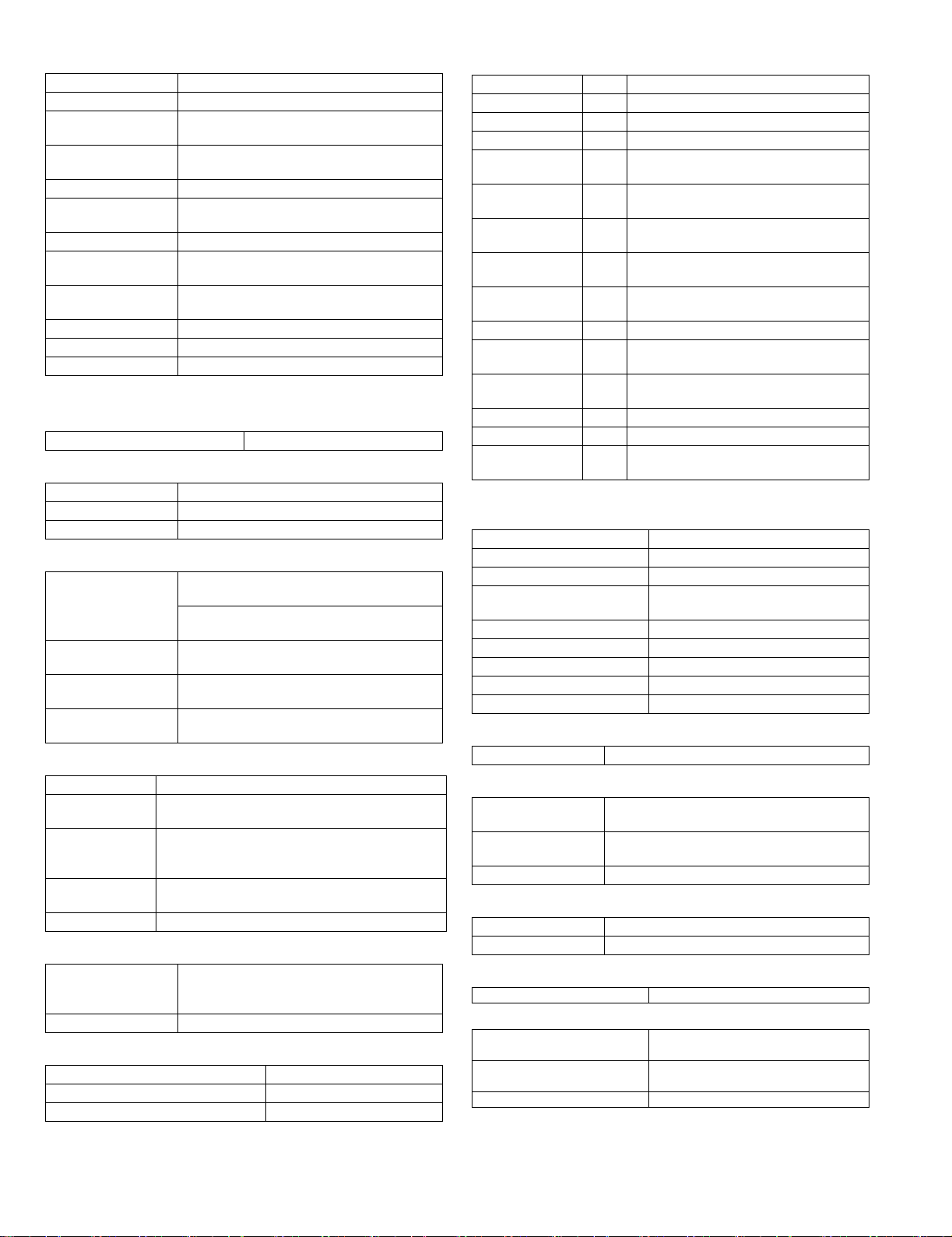
2. Environmental conditions
A. Transport conditions
(1) Transport conditions
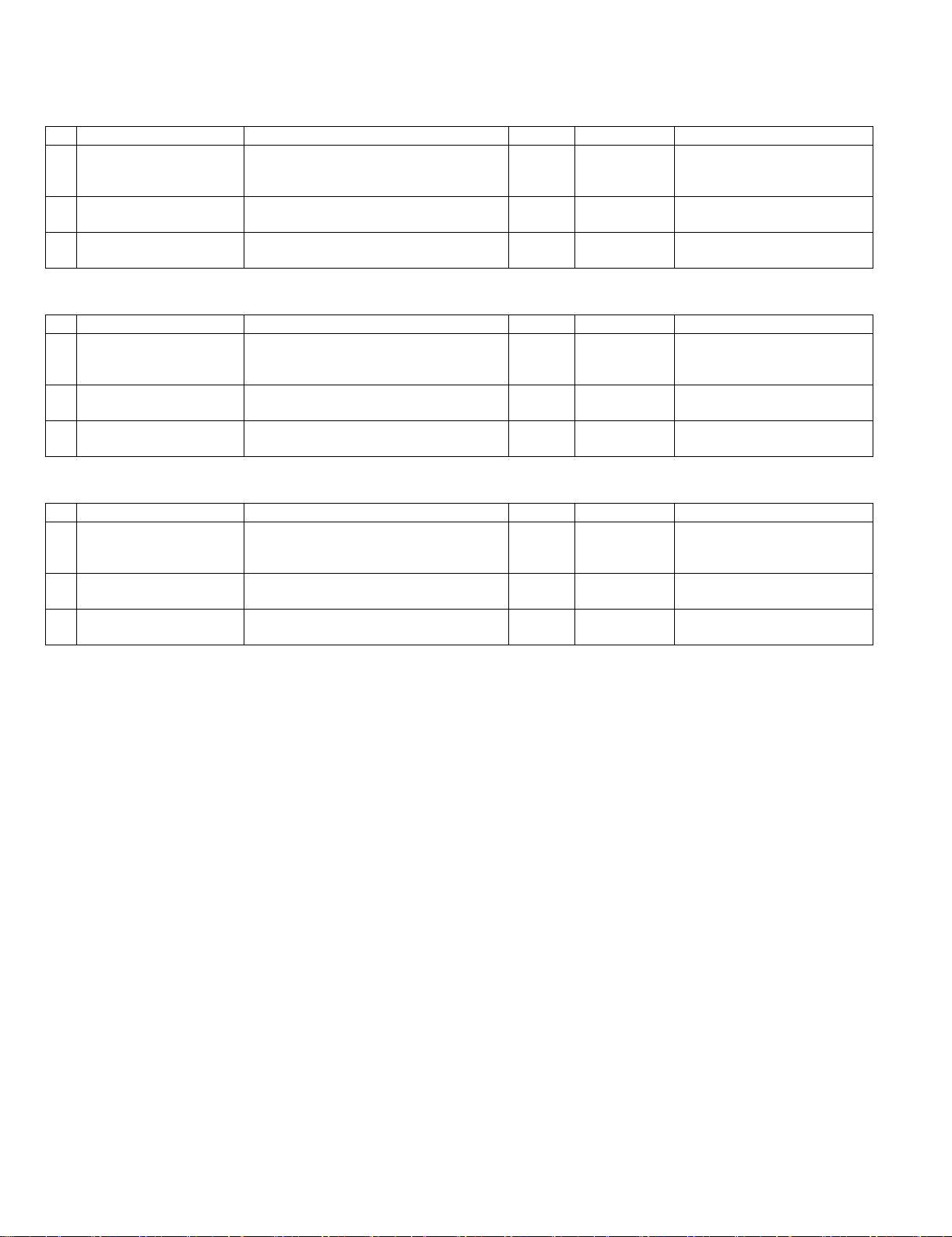
3. Production number identification
<Toner cartridge>
The label on the toner cartridge shows the date of production.
Humidity (%)
(2) Storage conditions
Humidity (%)
Temperature
Temperature
Ver.No.Production
place
Serial
number
Year/
Month/
Day
<Drum cartridge>
The lot number, printed on the front side flange, is composed of 6 digits,
each digit showing the following content:
123456
B. Use conditions
Use environment
conditions
Humidity (%)
Temperature
C. Life(packed conditions)
Photoconductor drum (36 months from the production month)
Developer, toner (24 months from the production month)
1 Alphabet
Indicates the model conformity code. A for this model.
2 Number
Indicates the end digit of the production year.
3 Number or X, Y, Z
Indicates the month of packing.
X stands for October, Y November, and Z December.
4/5 Number
Indicates the day of the month of packing.
6 Alphabet
Indicates the production factory. "A" for Nara Plant, “C“ for
SOCC
DP-1620 CONSUMABLE PARTS 3-2
Page 13
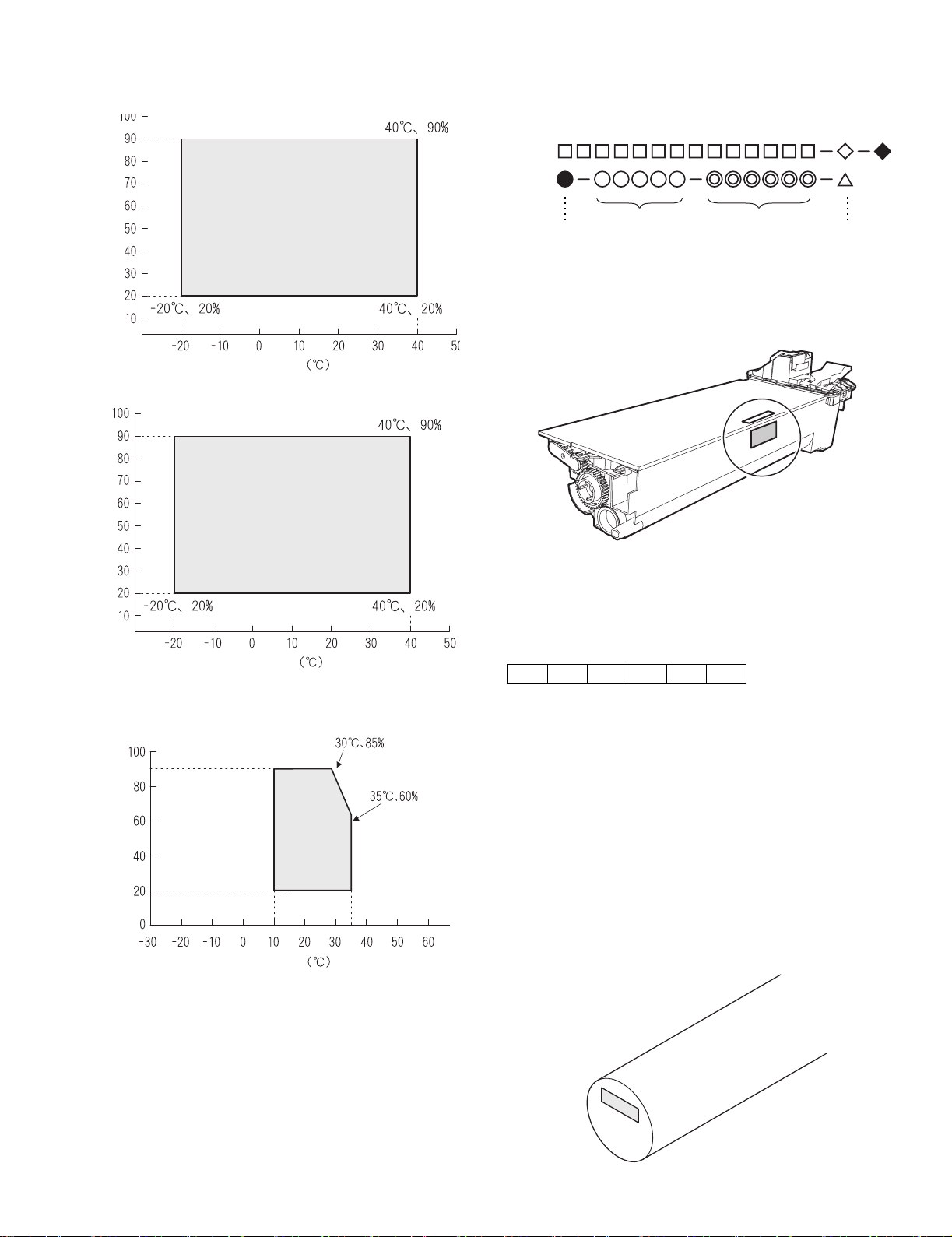
[4] EXTERNAL VIEWS AND INTERNAL STRUCTURES
1. Appearance
1
6
5
1
15
16
2
3
4
7
14
8
1 Document feeder cover (when the ADF
is installed) /document cover
4 Power switch 5 Operation panel 6 Paper output tray
7 Front cover 8 Paper trays 9 Side cover
10 Side cover handle 11 Bypass tray guides 12 Bypass tray
13 Bypass tray extension 14 Charger cleaner 15 USB 1.1 connector
16 Parallel connector
2 Document glass 3 Handles
11
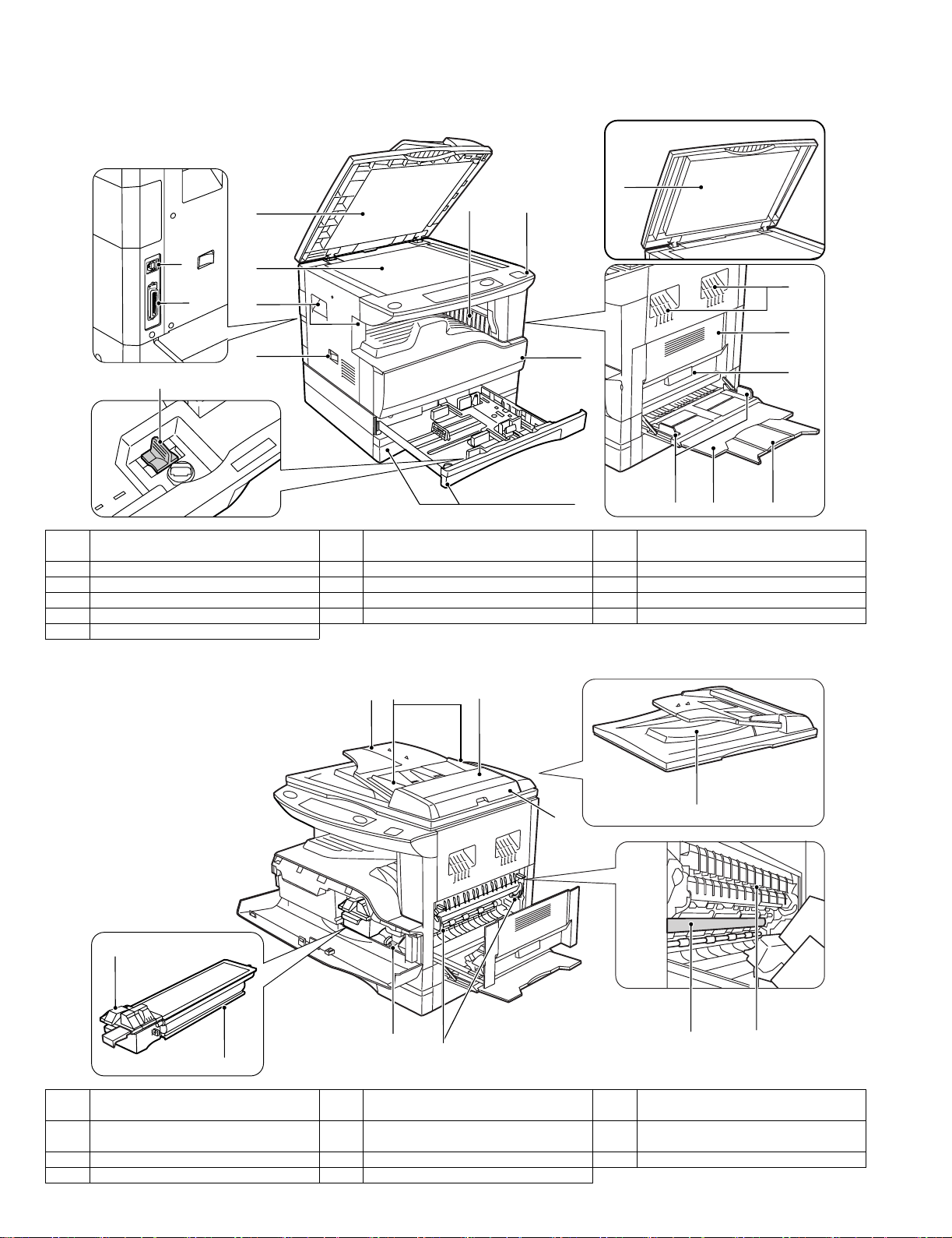
2. Internal
18
1917
3
9
10
12 13
20
21
22
24
25
2726
23
17 Document feeder tray
(when the ADF is installed)
20 Right side cover
(when the ADF is installed)
23 Toner cartridge 24 Roller rotating knob 25 Fusing unit release levers
26 Photoconductive drum 27 Fusing unit paper guide
DP-1620 EXTERNAL VIEWS AND INTERNAL STRUCTURES 4-1
18 Original guides
(when the ADF is installed)
21 Exit area
(when the ADF is installed)
19 Feeding roller cover
(when the ADF is installed)
22 Toner cartridge lock release lever
Page 14
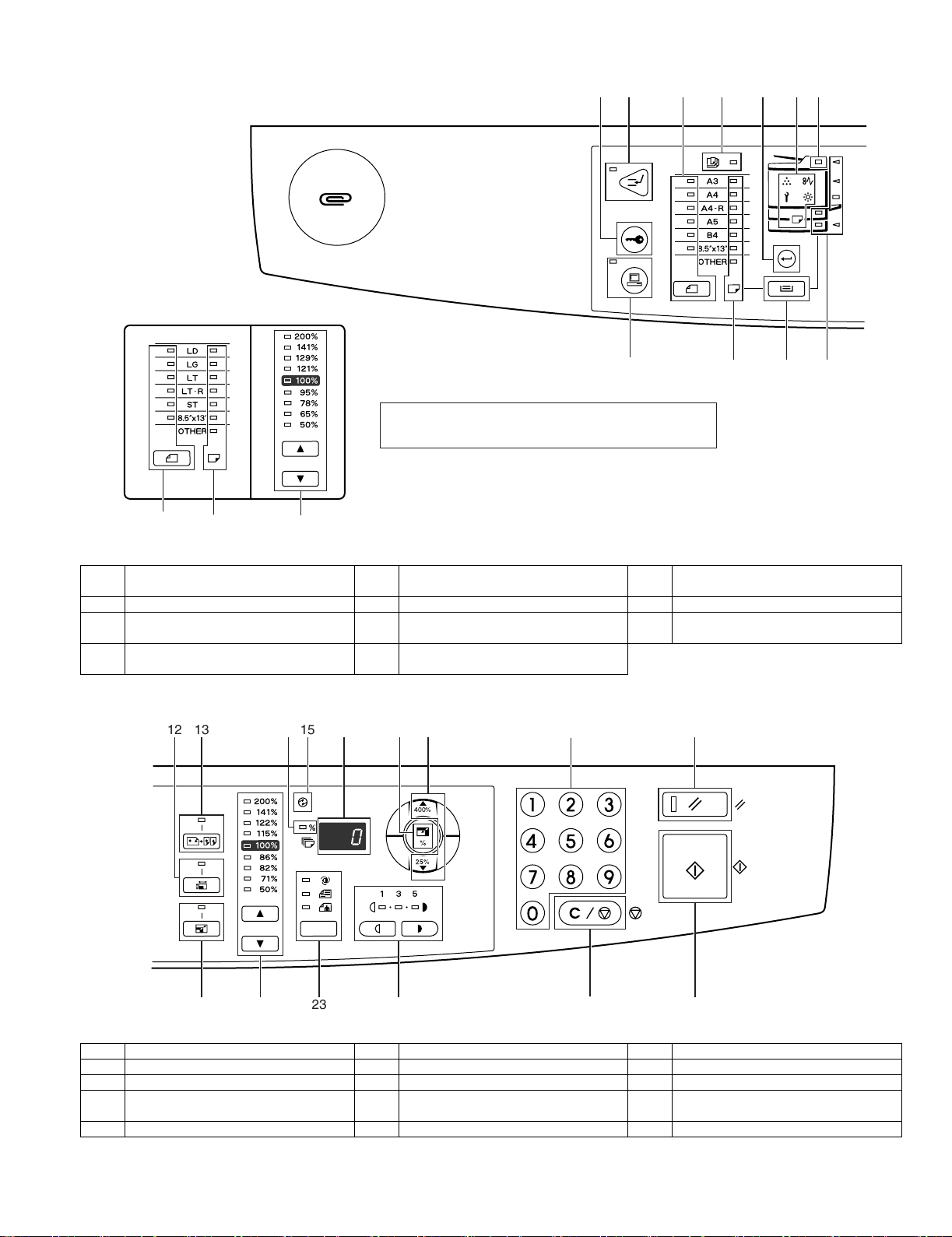
3. Operation Section
The example of a display of inch series
2
1
35
8 9 10 11
The indications of the operation panel may differ
depending on the country and the region.
6
4
7
39 22
1 AUDIT CLEAR key 2 INTERRUPT key / indicator 3 ORIGINAL SIZE ENTER key /
4 AUTO PAPER SELECT indicator 5 PAPER SIZE ENTER key 6 Alarm indicators
7ADF indicator
(when the SPF is installed)
10 TRAY SELECT key 11 Paper feed location / misfeed location
1312 15
8 ON LINE key/indicator 9 PAPER SIZE indicators
indicators
16
1714 18
"
#
19
ORIGINAL SIZE indicators
20
23
12 XY-ZOOM key/indicator 13 DUAL PAGE COPY key/indicator 14 ZOOM indicator
15 POWER SAVE indicator 16 Display 17 Copy ratio display key
18 Zoom keys 19 Numeric keys 20 RESET key
21 AUTO IMAGE key / indicator 22 PRESET RATIO selector keys /
24 Light and Dark keys / indicators 25 CLEAR STOP key 26 START key / indicator
DP-1620 EXTERNAL VIEWS AND INTERNAL STRUCTURES 4-2
2421 22
indicators
25
26
23 AUTO/TEXT/PHOTO key / indicators
Page 15
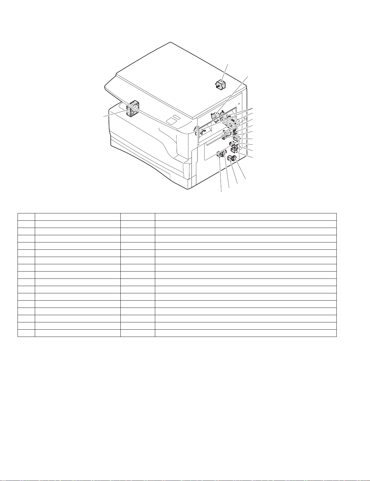
4. Motor, solenoid, clutch
16
15
1
14
13
2
3
4
5
6
7
8
9
10
11
12
No.
1 Mirror motor MRM Drives the optical mirror base (scanner unit).
2 Toner motor TM Toner supply
3 Cooling fan motor CFM Cools the inside of the machine.
4 Main motor MM Drives the machine.
5 1st tray paper feed clutch CPFC1 Drive the pick up roller
6 PS clutch RRC Drives the resist roller
7 Paper feed solenoid CPSOL1 Solenoid for paper feed from cassette
8 Resist roller solenoid RRS Resist roller rotation control solenoid
9 Manual paper transport clutch MPTC Drives the manual paper transport roller.
10 Manual paper feed clutch MPFC Drives the manual paper feed roller.
11 Manual paper feed solenoid MPFS Manual paper feed solenoid
12 2nd tray transport clutch CPFC2 Drives the 2nd tray transport roller.
13 2nd tray transport solenoid FSOL1 2nd tray transport solenoid
14 2nd tray paper feed clutch CPFC1 Drives the 2nd tray paper feed roller.
15 2nd tray paper feed solenoid PSOL2 2nd tray transport solenoid
16 Exhaust fan motor VFM Cools the inside of the machine.
Name
Code
Function operation
DP-1620 EXTERNAL VIEWS AND INTERNAL STRUCTURES 4-3
Page 16
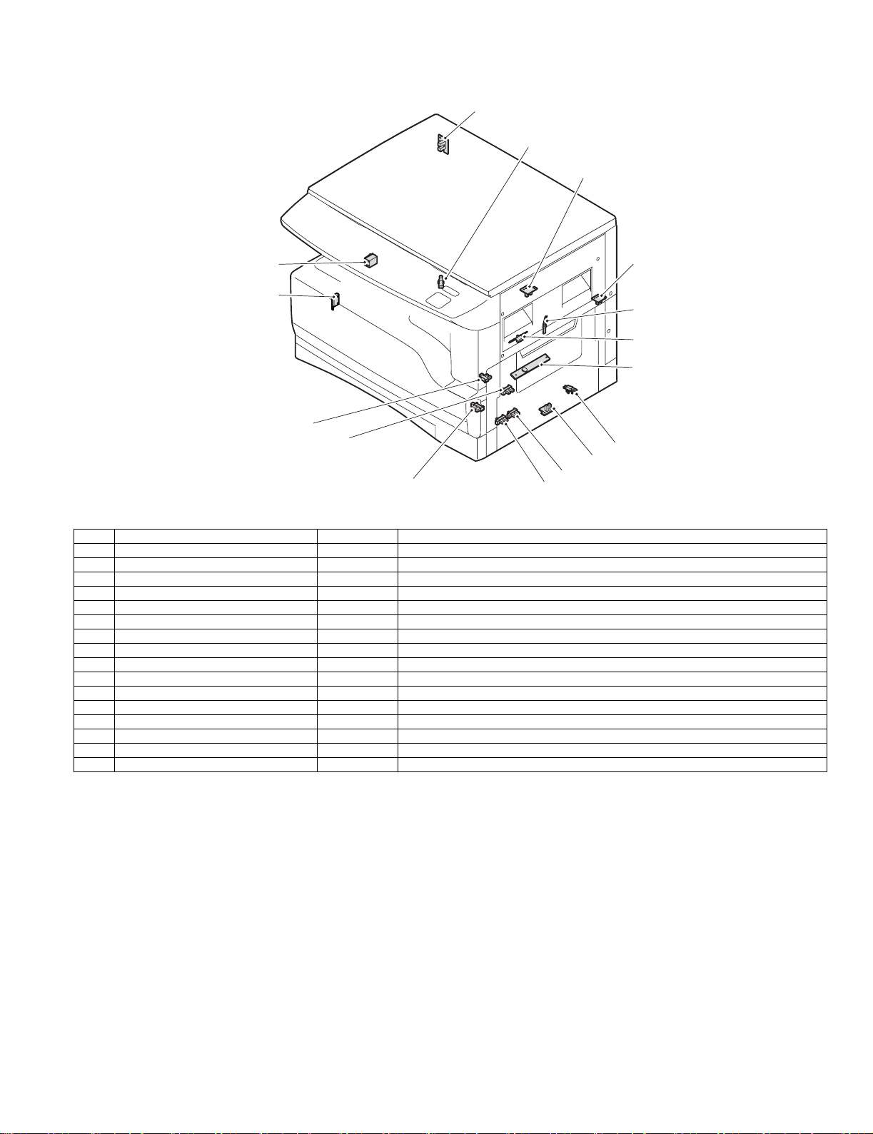
5. Sensor, switch
1
2
3
16
4
15
5
6
7
14
13
8
9
12
No. Name Code Function operation
1 Mirror home position sensor MHPS Detects the mirror (scanner unit) home position.
2 Side door switch DSWR Side door open detection
3 Paper exit sensor (paper exit side) POD1 Detects paper exit.
4 Paper exit sensor PDPX Paper transport detection
5 Thermistor RTH Fusing section temperature detection
6 Thermostat Fusing section abnormally high temperature detection
7 Toner density sensor TCS Toner quantity detection
8 2nd tray detection switch 2nd tray detection
9 Manual sensor MPED Manual transport detection
10 2nd tray door open/close sensor DRS2 2nd tray door open/close detection
11 2nd tray door paper pass sensor PPD2 2nd tray paper entry detection
12 2nd tray paper empty sensor CSS2 2nd tray paper empty detection
13 Paper in sensor PIN Paper transport detection
14 Cassette empty Tray paper entry detection
15 Front cover SW Front cover open detection
16 Power switch MAIN SW Turns ON/OFF the main power source.
10
11
DP-1620 EXTERNAL VIEWS AND INTERNAL STRUCTURES 4-4
Page 17
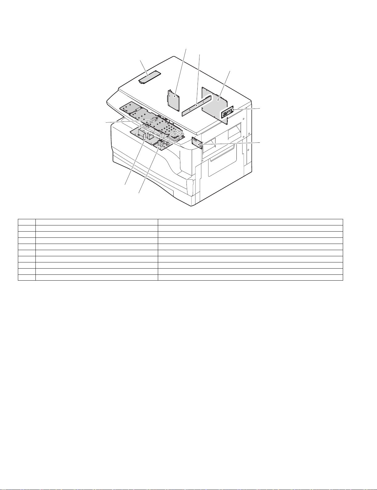
6. PWB unit
2
3
1
4
5
9
6
8
7
No. Name Function operation
1 Copy lamp Inverter PWB Copy lamp control
2 I / F PWB USB1.1, IEEE1284 I/F
3 CCD sensor PWB Image scanning
4 Main control PWB Main control PWB
5 Tray PWB Shifter motor control
6 2nd cassette PWB 2nd cassette control
7 High voltage PWB High voltage control
8 Power PWB AC power input/DC power control
9 Operation main PWB Operation panel input/Display, operation panel section control
DP-1620 EXTERNAL VIEWS AND INTERNAL STRUCTURES 4-5
Page 18

7. Cross sectional view
18
1 4
2
53
6
7
8
9
10
11
12
13
14
15
16171920212223
No. Name Function/Operation
1 Copy lamp Image radiation lamp
2 Copy lamp unit Operates in synchronization with No. 2/3 mirror unit to radiate documents
3 LSU unit Converts image signals into laser beams to write on the drum.
4 Lens unit Reads images with the lens and the CCD.
5 MC holder unit Supplies negative charges evenly on the drum.
6 Paper exit roller Used to discharge paper.
7 Transport roller Used to transport paper.
8 Upper heat roller Fuses toner on paper (with the teflon roller).
9 Lower heat roller Fuses toner on paper (with the silicon rubber roller).
10 Waste toner transport roller Transports waste toner to the waste toner box.
11 Drum unit Forms images.
12 Transfer charger unit Transfer images (on the drum) onto paper.
13 DUP follower roller
14 Duplex transport roller Transports paper for duplex .
15 Resist roller Takes synchronization between the paper lead edge and the image lead edge.
16 Manual paper feed tray Manual paper feed tray
17 Manual paper pick up roller Picks up paper in manual paper feed.
18 No. 2/3 mirror unit Reflects the images from the copy lamp unit to the lens unit.
19 Manual transport roller Transports paper from the manual paper feed port.
20 2nd tray paper transport roller Transports paper from the 2nd tray.
21 2nd tray paper pick up roller
(semi-circular roller)
22 1st tray paper feed roller
(semi-circular roller)
23 MG roller Puts toner on the OPC drum.
sequentially.
Picks up paper from the 2nd tray.
Picks up paper from the 1st tray.
DP-1620 EXTERNAL VIEWS AND INTERNAL STRUCTURES 4-6
Page 19
[5]UNPACKING AND INSTALLATION
1.Installing conditions
A.Copier installation
Do not install your copier in areas that are:
•damp, humid, or very dusty
•exposed to direct sunlight
•poorly ventilated
•subject to extreme temperature or humidity changes, e.g., near an air
conditioner or heater.
•Be sure to allow the required space around the machine for servicing
and proper ventilation.
B.Power source
•Use an exclusive-use power outlet. If the power plug of this machine is
inserted into a power outlet commonly used with other illumination
units, flickers of the lamp may be result. Use a power outlet which is not
used commonly with any illumination units.
•Avoid complex wiring.
C.Grounding wire connection.
•To avoid danger, be sure to connect a grounding wire. If no grounding
wire is connected and a leakage occurs, a fire or an electric shock may
be result.
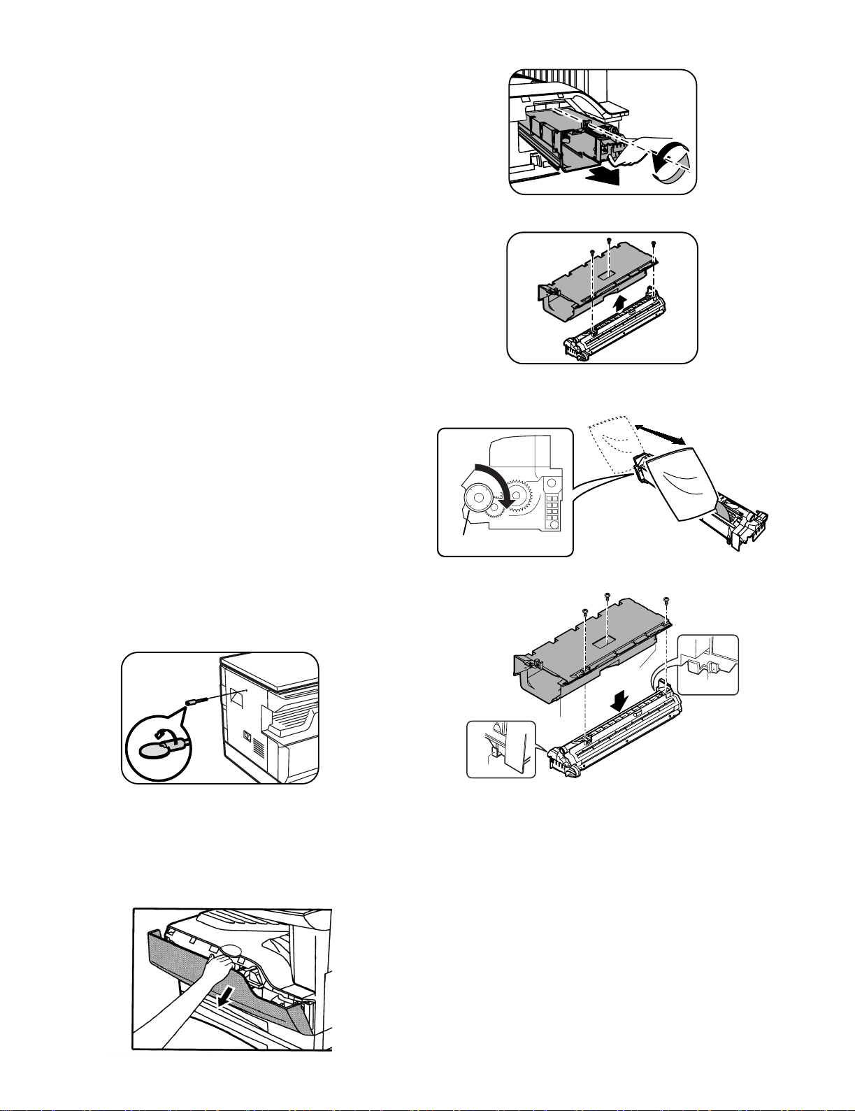
2) Loosen the screw and remove the developer cartridge.
3) Remove the developer tank from the developer cartridge.
4) Supply developer into the developer tank while rotating the MG roller
in the arrow direction.
2.Removal of protective material and fixing screw
1) Remove all tapes and protective material.
•Remove all tapes, then open the document cover and remove the
protective material of sheet shape
2) Remove the fixing screw.
•Use a coin to remove the fixing screw.
•The fixing screw is required when transporting the machine. Keep it in
the tray. (Refer to the later description.)
3.Installing procedure
A.Developer cartridge installation
1) Open the front cover.
•Pull on the top center of the front cover to open.
MG roller
* Shake the developer bag enough before opening it.
Hole
Hook
Hole
Hook
Note:Check that the DV seal is free from developing agent. If developing
agent is attached to the DV seal, clean it carefully.
Check to insure that the hook is engaged in two positions.
5) Attach the developer tank to the developer cartridge.
* After supplying developer into the developer cartridge, do not tilt or
shake the developer cartridge.
6) Attach the developer cartridge to the copier, and fix it with the screw.
DP-1620 UNPACKING AND INSTALLATION 5-1
Page 20
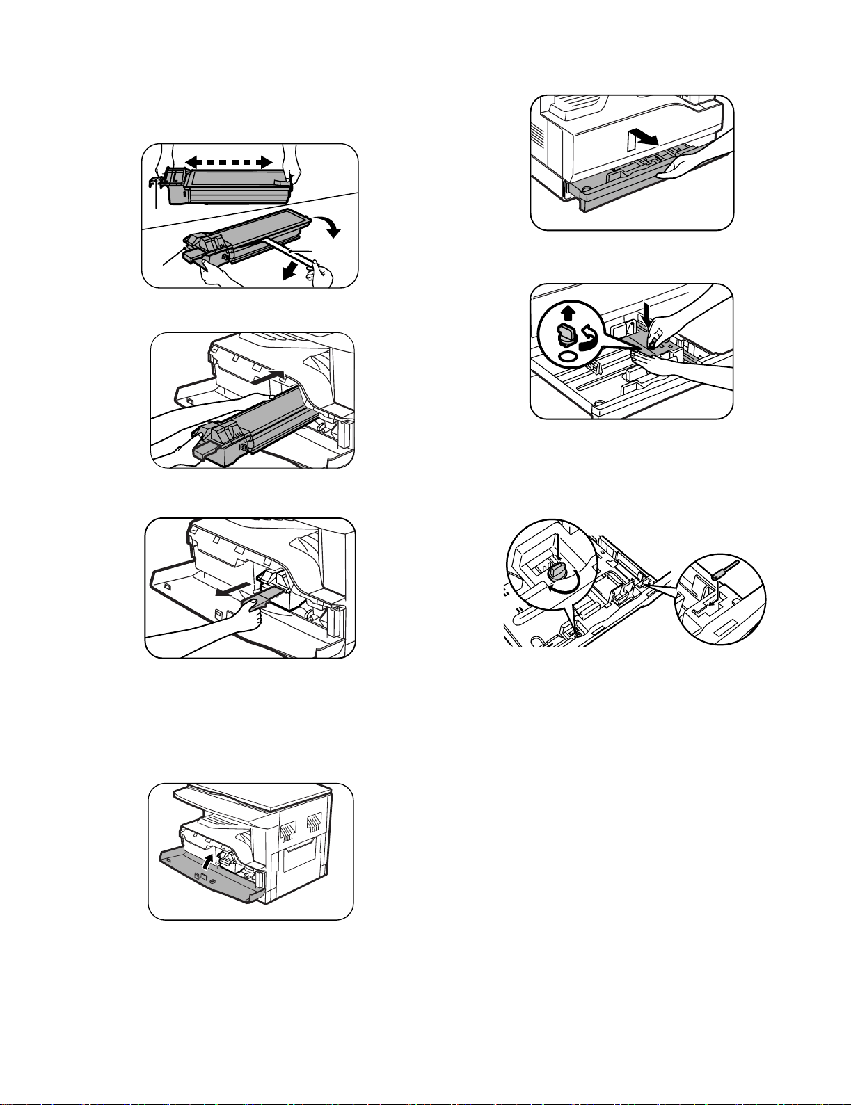
B.Toner cartridge installation
1) Shake the toner cartridge several times horizontally, and remove the
tape.
* Do not hold the shutter lever when shaking.
* After removing the tape, do not tilt or shake the toner cartridge.
4 or 5 times
Shutter
4.Removal and storage of fixing screw
1) Lift the knob and gently pull out the tray.
Handle
2) Attach the toner cartridge to the copier.
3) Pull the shutter lever.
Tape
2) Hold the paper pressure plate and turn the fixing screw in the arrow
direction.
3) Store the fixing pin and the fixing screw in the tray.
•Store the fixing screw which was removed in the above procedure 2 and
the fixing screw which was removed in procedure 2 of 2.
•Removal of protective material and fixing screw in the storage place in
the tray.
Close the front cover A, then close the side cover B.
•When closing the front cover, gently press the both sides.
•When closing the side cover, hold the knob.
•When closing the covers, be sure to close the front cover first, then
close the side cover. If closed in a wrong sequence, the covers may be
broken.
DP-1620 UNPACKING AND INSTALLATION 5-2
Page 21
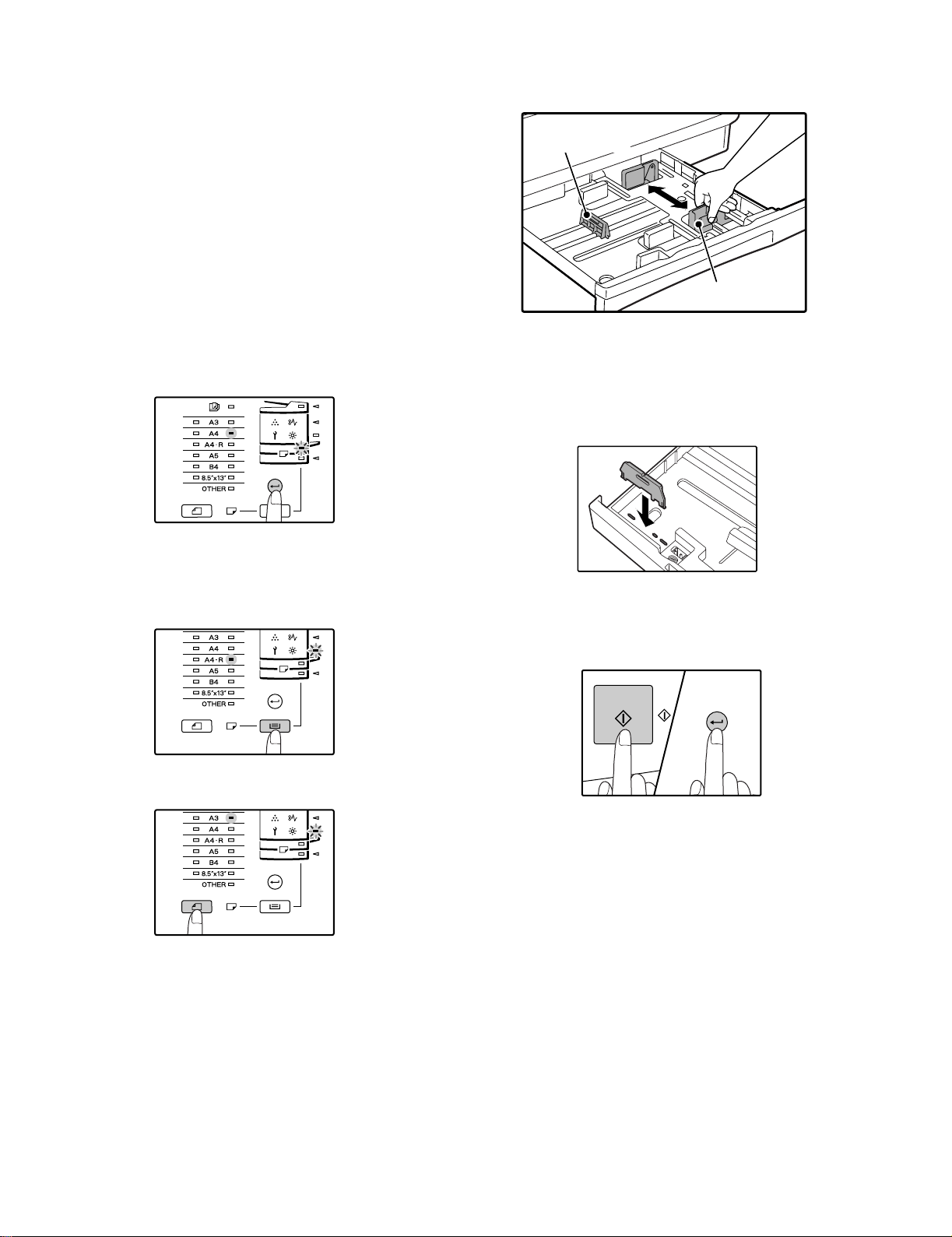
5. Changing a tray's paper size setting
Follow these steps to change a tray's paper size setting.
Note:
•The paper size setting cannot be changed when the machine has
stopped temporarily due to running out of paper or a misfeed, or during
interrupt copying.
•During printing (even in copy mode), the paper size setting cannot be
changed.
•A5 (ST) size paper can only be selected in upper paper tray.
•Do not load paper that is a different size than the paper size setting.
Copying will not be possible.
4) Squeeze the lock lever of the front guide and slide the front guide to
match the width of the paper, and move the left guide to the
appropriate slot as marked on the tray.
Left guide
1) Hold down the [PAPER SIZE ENTER] key for more than 5 seconds to
set the selected paper size.
The currently selected paper feed location indicator will blink and the
corresponding paper size (which is currently set) indicator will light
steadily.
All other indicators will go out.
2) If the machine has two paper trays, use the [TRAY SELECT] key to
select the paper tray for which you wish to change the paper size
setting.
Each time the [TRAY SELECT] key is pressed, a paper tray will be
indicated with a blinking paper feed location indicator.
Front guide
•The front guide is a slide-type guide. Grasp the locking knob on the
guide and slide the guide to the indicator line of the paper to be loaded.
•The left guide is an insert-type guide. Remove it and then insert it at the
indicator line of the paper to be loaded.
•When using LD sized paper store the left guide in the slot at the left front
of the paper tray.
5) Press the [START] key and then the [PAPER SIZE ENTER] key.
To change the paper size setting of another tray, repeat steps 2) to 5)
after pressing the [START] key.
3) Use the [ORIGINAL SIZE ENTER] key to select the paper size.
The indicator of the selected paper size lights up.
DP-1620 UNPACKING AND INSTALLATION 5-3
Note:Affix the paper size label for the paper size selected in step 3) to
the label position on the right end of the tray.
Important points when using the printer mode
•Make sure that the tray's paper size setting is the same as the tray's
paper size setting in the printer driver. For example, if the tray's paper
size setting is A4R (LT-R), set "Setting Paper Size" to "A4-R". For more
information, see "CONFIGURING THE PRINTER DRIVER" in the
"Software Setup Guide".
Page 22
[6]ADJUSTMENTS
1.Adjustment item list
Section Adjustment item Adjustment procedure/SIM No.
A Process
section
B Mechanism
section
C Image density
adjustment
(1) Developing doctor gap adjustment Developing doctor gap adjustment
(2) MG roller main pole position adjustment MG roller main pole position adjustment
(3) Developing bias voltage check
(4) Main charger voltage check
(1) Image position adjustment SIM-50
(2) Main scanning direction (FR direction) distortion balance
adjustment
No. 2/3 mirror base unit installing position adjustment
Copy lamp unit installing position adjustment
(3) Main scanning direction (FR direction) distortion adjustment Rail height adjustment
(4) Sub scanning direction (scanning direction) distortion
Winding pulley position adjustment
adjustment
(5) Main scanning direction (FR direction) magnification ratio
SIM 48-1
adjustment
(6) Sub scanning direction (scanning direction) magnification ratio
adjustment
OC mode in copying (SIM 48-1)
SPF mode in copying (SIM 48-5)
(7) Off center adjustment OC mode (SIM 50-12)
SPF mode (SIM 50-12)
(8) SPF white correction pixel position adjustment
(
required in an SPF model when replacing the lens unit)
SIM63-7
(1) Copy mode SIM 46-1
2.Copier adjustment
A.Process section
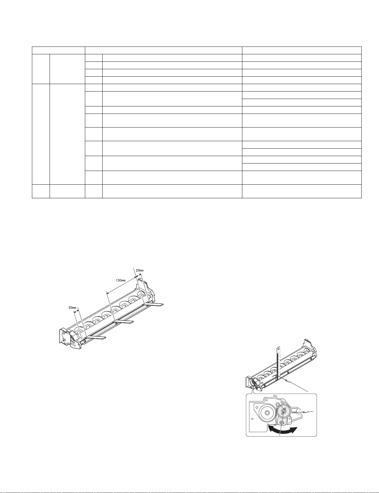
(1) Developing doctor gap adjustment
1) Loosen the developing doctor fixing screw A.
2) Insert a thickness gauge of 1.5mm to the three positions at 20mm
and 130mm from the both ends of the developing doctor as shown.
3) Push the developing doctor in the arrow direction, and tighten the
developing doctor fixing screw. (Perform the same procedure for the
front and the rear frames.)
4) Check the clearance of the developing doctor. If it is within the
specified range, then fix the doctor fixing screw with screw lock.
* When inserting a thickness gauge, be careful not to scratch the
developing doctor and the MG roller.
(2) MG roller main pole position adjustment
1) Remove and separate the waste toner box and put the developing
unit on a flat surface.
2) Tie a string to a needle or a pin.
3) Hold the string and bring the needle close to the MG roller
horizontally. (Do not use paper clip, which is too heavy to make a
correct adjustment.) (Put the developing unit horizontally for this
adjustment.)
4) Do not bring the needle into contact with the MG roller, but bring it to
a position 2 or 3mm apart from the MG roller. Mark the point on the
MG roller which is on the extension line from the needle tip.
5) Measure the distance from the marking position to the top of the
doctor plate of the developing unit to insure that it is 18mm.
If the distance is not within the specified range, loosen the fixing
screw A of the main pole adjustment plate, and move the adjustment
plate in the arrow direction to adjust.
<Adjustment specification>
Developing doctor gap
Both ends (20mm from the both ends) :
C (Center) (150mm from the both ends) :
+0.1
1.5 mm
- 0.15
+0.15
1.55 mm
- 0.2
DP-1620 ADJUSTMENT 6-1
Page 23
(3)Developing bias voltage check
Note:Use a digital multi-meter with an internal resistance of 10MΩ or
more.
1) Set the digital multi-meter range to DC700V.
2) Put the test rod of the digital multi-meter on the developing bias
voltage output check pin.
3) Turn on the power, execute SIM25-1.
<Specification>
Mode Specification
Developing bias voltage DC - 400±8V
(4) Grid bias voltage check
Note:Use a digital multi-meter with an internal resistance of 10MΩ or
more.
B.Mechanism section
Note: If a jam error or paper empty occurs during copying in the
adjustment by the simulation, the image data are not saved, and
therefore recopying is required.
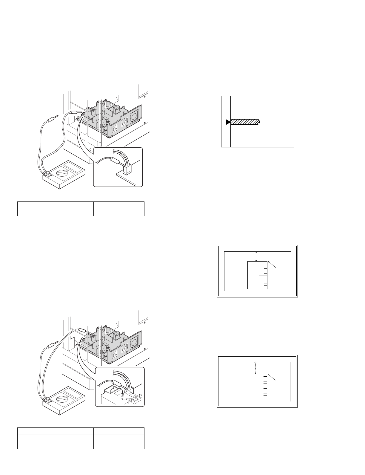
(1)Image position adjustment
a.OC image lead edge position adjustment (SIM 50-1)
Note:In advance to this adjustment, the sub scanning magnification ratio
adjustment must be performed.
1) Set a scale on the OC table as shown below.
2) Make a copy.
3) Check the copy output. If necessary, perform the following
adjustment procedures.
4) Execute SIM 50-1.
5) Set the OC lead edge position set value (Exposure display
<<PHOTO>> ON) to [1]
The OC image scanning start position is shifted inside the document
edge.
6) Set the main cassette lead edge void adjustment value (Exposure
display <<TEXT>> ON) * to [1]
The lead edge void becomes the minimum.
7) Set the main cassette print start position value (Exposure display
<<AUTO+MAIN CASSETTE LAMP>> ON) to [1] and make a copy.
The print start position is shifted inside the document edge.
1) Set the digital multi-meter range to DC700V.
2) Put the test rod of the digital multi-meter on the grid bias voltage
output check pin.
3) Turn on the power.
(The voltage is outputted in the grid bias High output mode during
warming up, and in the grid bias Low output mode when warming up
is completed.)
<Specification>
Mode Specification
Grid bias LOW DC - 400±8V
Grid bias HIGH DC - 525±10V
5mm
5
10
*The dimension varies depending on the model.
4mm
8) Measure the image loss R of the copied image. Enter the set value of
the image scanning lead edge position (Exposure display
<<PHOTO>> ON) again.
•1 step of the set value corresponds to about 0.1mm shift.
•Calculate the set value from the formula below.
R/0.1(mm) = Image loss set value
<R: Image loss measurement value (mm)>
5mm
5
10
* The scanning edge is set.
(A line may be printed by scanning the document edge.)
0mm
Example: 4/0.1 = 40 = about 40
Note:If the set value is not obtained from the above formula, perform the
fine adjustment.
DP-1620 ADJUSTMENT 6-2
Page 24
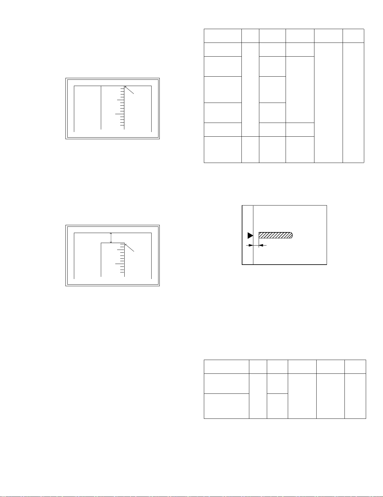
9) Measure the distance H between the paper lead edge and the image
print start position. Set the image print start position set value
(Exposure display <<AUTO+MAIN CASSETTE LAMP>> ON) again.
•1 step of the set value corresponds to about 0.1mm shift.
•Calculate the set value from the formula below.
H/0.1(mm) = Image print start position set value
<H: Print start position measurement value (mm)>
0mm
5
10
0mm
<Adjustment specification>
Adjustment
mode
OC image lead
edge position
Main cassette
print start
position
2nd cassette
print start
position
SIM LED Set
value
SIM
PHOTO R/0.1 Lead edge
50-1
AUTO
B/0.1
+
MAIN
AUTO
+
2nd
CASSETTE
Multi bypass
tray print start
position
AUTO
+
MULTI
Lead edge void TEXT B/0.05
Spec
value
void:
1 - 4mm
Image loss:
3mm or
less
Set
range
1 ~ 99
*Fit the print edge with the paper edge, and perform the
lead edge adjustment.
Example: 5/0.1 = 50 = about 50
Note:If the set value is not obtained from the above formula, perform the
fine adjustment.
10) Set the lead edge void adjustment value (Exposure display
<<TEXT>> ON)* again.
•1 step of the set value corresponds to about 0.1mm shift.
•Calculate the set value from the formula below.
B/0.05 (mm) = Lead edge void adjustment value
<B: Lead edge void (mm)>
2.5mm
5
10
2.5mm
Example: When setting the lead edge void to 2.5mm
:2.5 /0.05 = about 50
Note:If the set value is not obtained from the above formula, perform the
fine adjustment.
* 2nd cassette lead edge void adjustment: Exposure display <<AUTO
+ TEXT + PHOTO>>
Multi bypass tray lead edge void adjustment: Exposure display
<<TEXT + PHOTO>>
OC 2nd print
surface lead
SIM
50-19*
PHOTO 1 step:
0.1mm shift
edge position
adjustment
* (Set to S → D mode for before execution)
b.SPF image lead edge position adjustment (SIM50-6)
1) Set a scale on the OC table as shown below.
Note:Since the printed copy is used as a test chart, put the scale in
paralled with the edge lines.
2) Make a copy, Then use the copy output as an original to make an
SPF copy again.
3) Check the copy output. If necessary, perform the following
adjustment procedures.
4) Execute SIM 50-6.
5) Set the SPF lead edge position set value (Exposure display
<<AUTO>> ON) so that the same image is obtained as that obtained
in the previous OC image lead edge position adjustment.
<Duplex mode adjustment>
OC 2nd print surface (Auto duplex) lead edge position adjustment:
SIM50-19 <<PHOTO>>
* For the adjustment procedure, set to S → D mode before execution.
Note:Before performing the 2nd print surface lead edge position
adjustment and the lead edge void adjustment, be sure to perform
the 1st print surface lead edge position adjustment in advance, and
be sure to perform the 2nd print surface lead edge position
adjustment and then the lead edge void adjustment in this
sequence.
DP-1620 ADJUSTMENT 6-3
<Adjustment specification>
Adjustment mode SIM LED Set value Spec value Set
range
SPF image lead
edge position
(1st print surface)
SIM
50-6
AUTO 1 step:
0.1mm shift
Lead edge
void:
1 - 4mm
1 ~ 99
(2nd print surface) TEXT
Image loss:
3mm or
less
Page 25
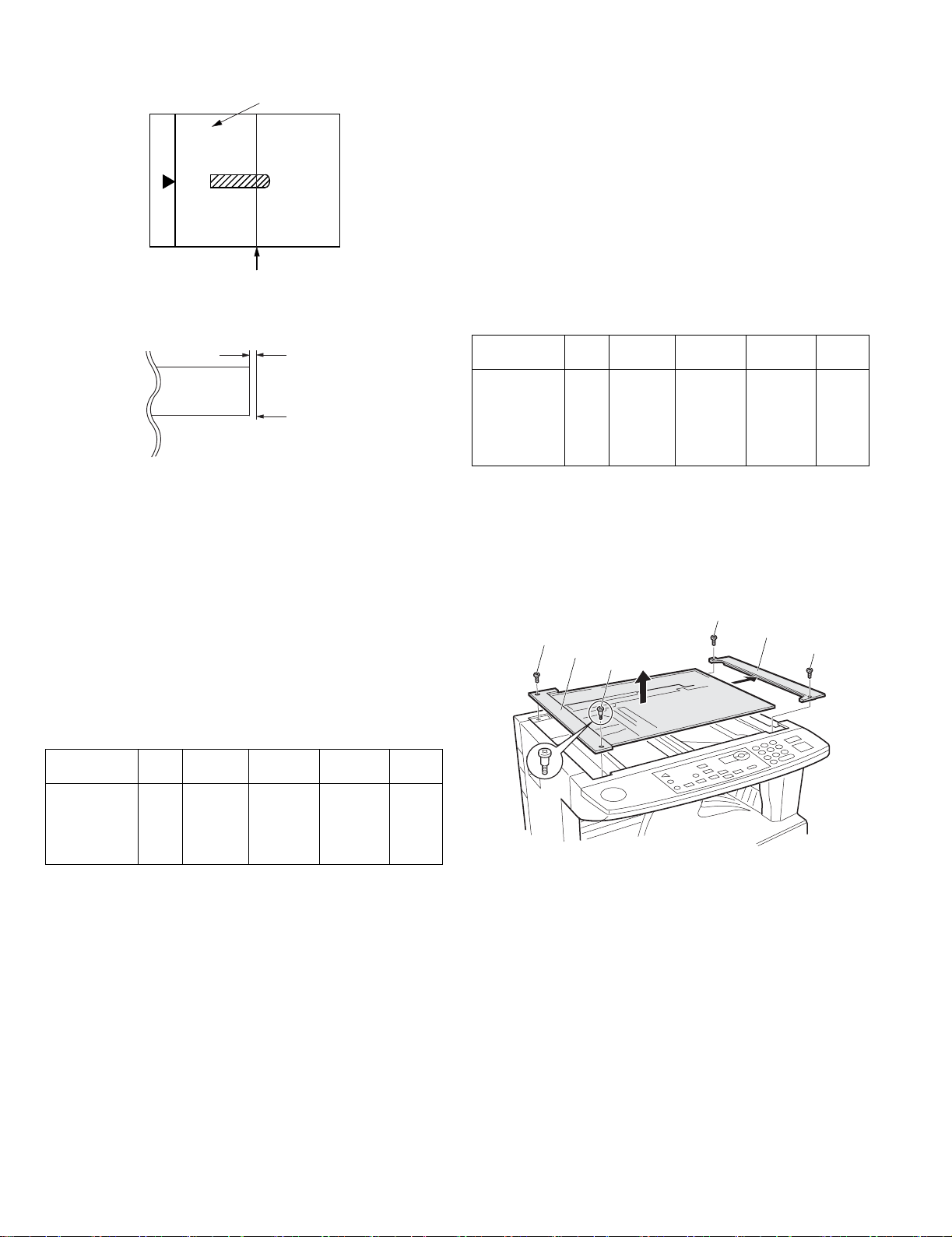
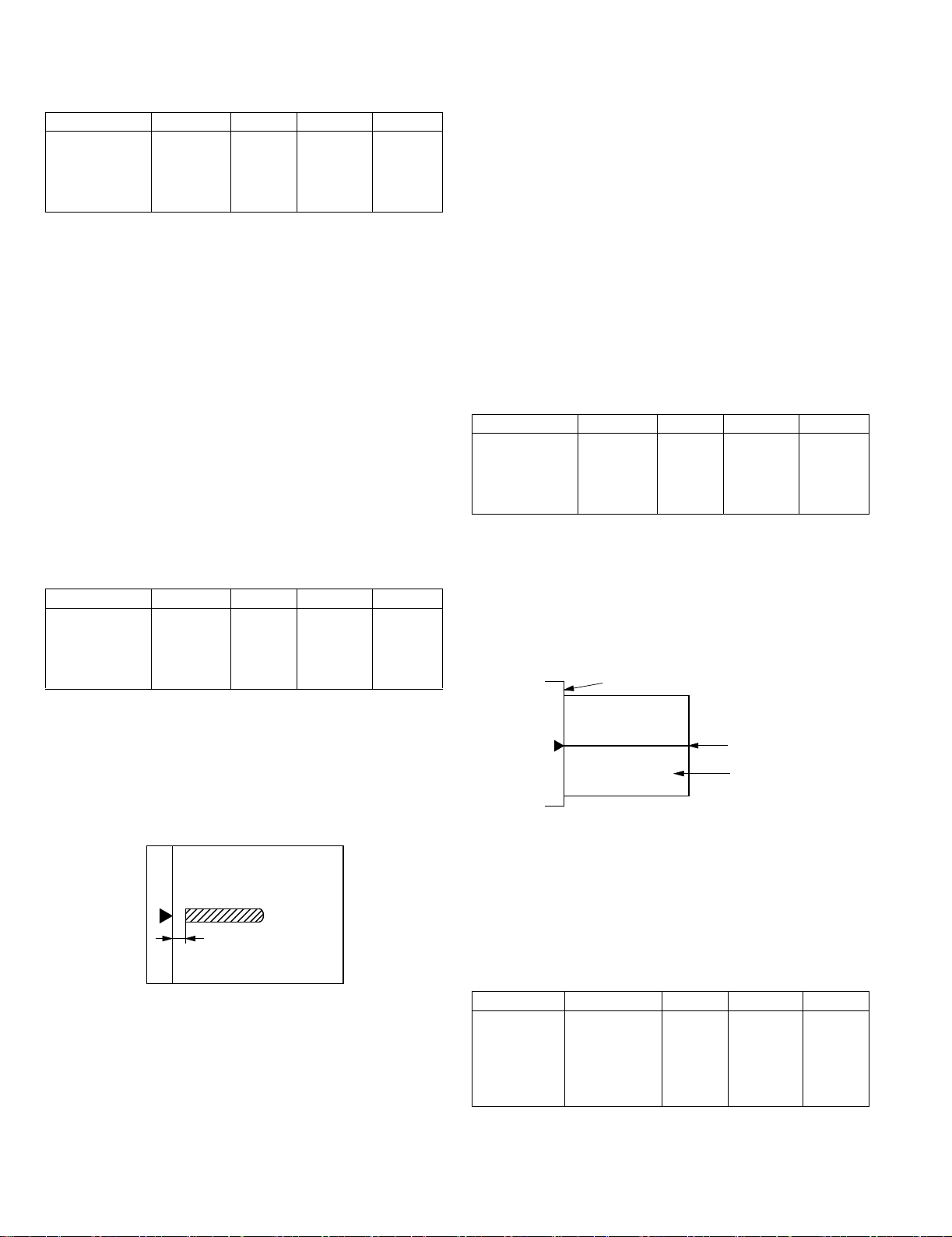
c.Rear edge void adjustment (SIM50-1, SIM50-19)
1) Set a scale as shown in the figure below.
A4(8.5" x 11")
Paper rear edge
2) Set the document size to A4 (8.5" x 11"), and make a copy at 100%.
3) If necessary, perform the following adjustment procedure.
Void amount (Standard value: 4mm or less)
Scale image
Paper rear edge
4) Execute SIM 50-1 and set the density mode to AUTO + TEXT +
PHOTO (Rear edge void).The currently set adjustment value is
displayed.
5) Enter the set value and press the start key. The correction value is
stored and a copy is made.
<Duplex mode adjustment>
* 1st print surface (auto duplex) rear edge void adjustment:
SIM50-19 <<AUTO>>
* 2nd print surface (auto duplex) rear edge void adjustment:
SIM50-19<<TEXT>>
*Set to S → D mode before execution.
Note:Before performing the 2nd print surface rear edge void adjustment,
be sure to perform the 2nd print surface lead edge position
adjustment. Never reverse the sequence.
<Adjustment specification>
Mode SIM LED Set value Specifi-
Rear edge void SIM
50-1
AUTO
+
1 step:
0.1mm shift
cation
4mm or
less
Set
range
1 ~ 99
TEXT
+
PHOTO
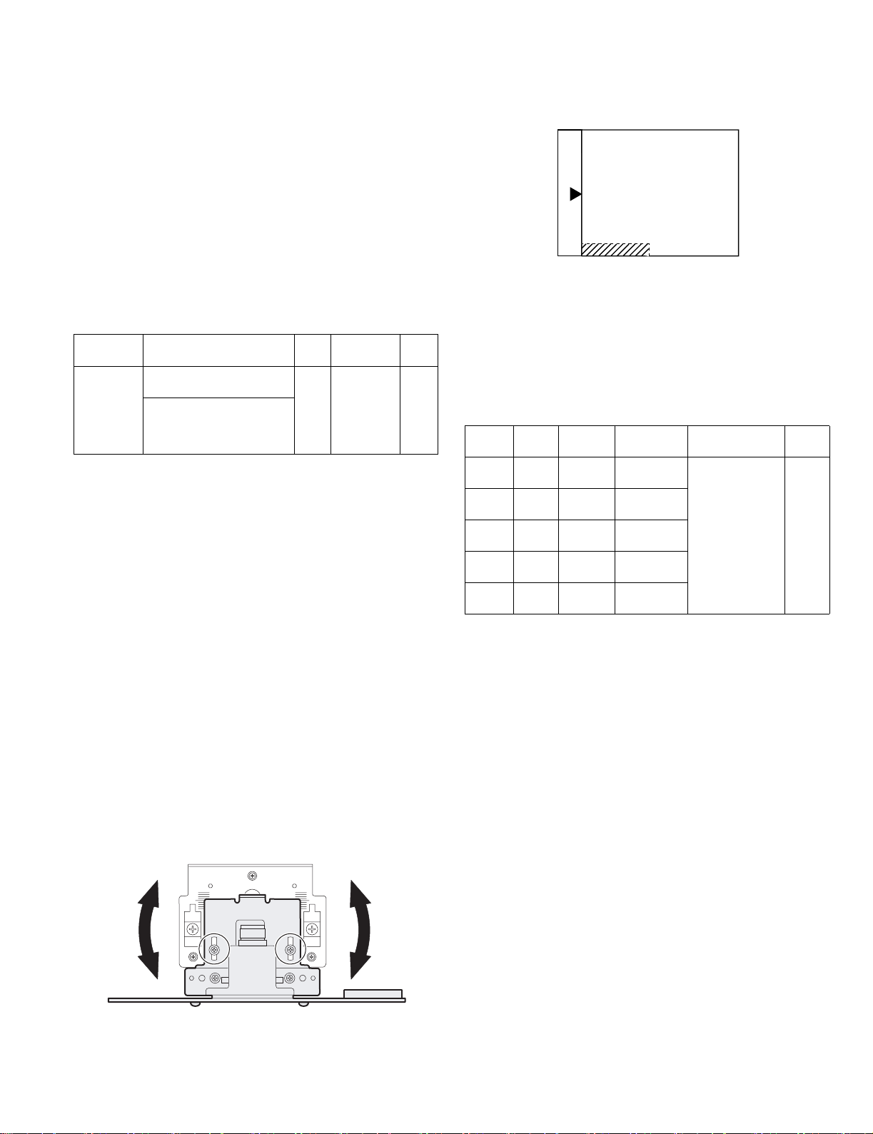
e.Side edge void area adjustment (SIM26-43)
Note:Before performing this adjustment, be sure to check that the paper
off center adjustment (SIM 50-10) is completed.
1) Set a test chart on the document table.
2) Select a paper feed port and make two copies. Compare the 2nd
copy and the test chart. If necessary, perform the following
adjustment procedure.
* The 1st copy does not show the void. Be sure to check the 2nd copy.
3) Execute SIM 26-43 and set the density mode to AUTO(right edge
void) + TEXT (Left edge void).
The currently set adjustment value is displayed.
4) Enter the set value and press the start key. The correction value is
stored.
<Adjustment specification>
ode SIM LED Set value Specifi-
Left edge void SIM
26-43
AUTO
(right
1 step:
0.5mm shift
cation
0.5 ~ 4mm 1 ~ 99
Set
range
edge)
+
TEXT
(left edge)
* The void adjustment values on the right and the left must be the
same.
(2) Main scanning direction(FR direction) distortion balance
adjustment
1) Remove the OC glass and the right cabinet.
(3)
(1)
(2)
(1)
(4)
(3)
d. Paper off center adjustment (SIM50-10)
1) Set a test chart on the document table.
2) Select a paper feed port and make a copy. Compare the copy and
the test chart. If necessary, perform the following adjustment
procedure.
3) Execute SIM 50-10. After completion of warm-up, shading is
performed and the currently set off center adjustment value of each
paper feed port is displayed.
4) Enter the set value and press the start key. The correction value is
stored and a copy is made.
DP-1620 ADJUSTMENT 6-4
Page 26
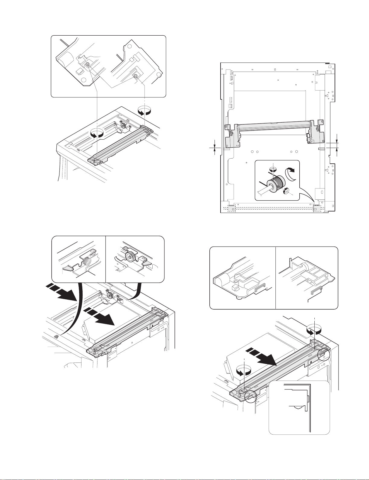
2) Loosen the copy lamp unit wire fixing screw.
Wire fixing screw
3) Manually turn the mirror base drive pulley and bring No. 2/3 mirror
base unit into contact with the positioning plate. At that time, if the
front frame side and the rear frame side of No. 2/3 mirror base unit
are brought into contact with the positioning plate at the same time,
the mirror base unit parallelism is proper. If one of them is in contact
with the positioning plate, perform the adjustment of 4).
4) Loosen the set screw of the scanner drive pulley which is not in
contact with No. 2/3 mirror base unit positioning plate.
5) Without moving the scanner drive pulley shaft, manually turn the
scanner drive pulley until the positioning plate is brought into contact
with No. 2/3 mirror base unit, then fix the scanner drive pulley.
6) Put No. 2/3 mirror base unit on the positioning plate again, push the
projections on the front frame side and the rear frame side of the
copy lamp unit to the corner frame, and tighten the wire fixing screw.
DP-1620 ADJUSTMENT 6-5
Page 27
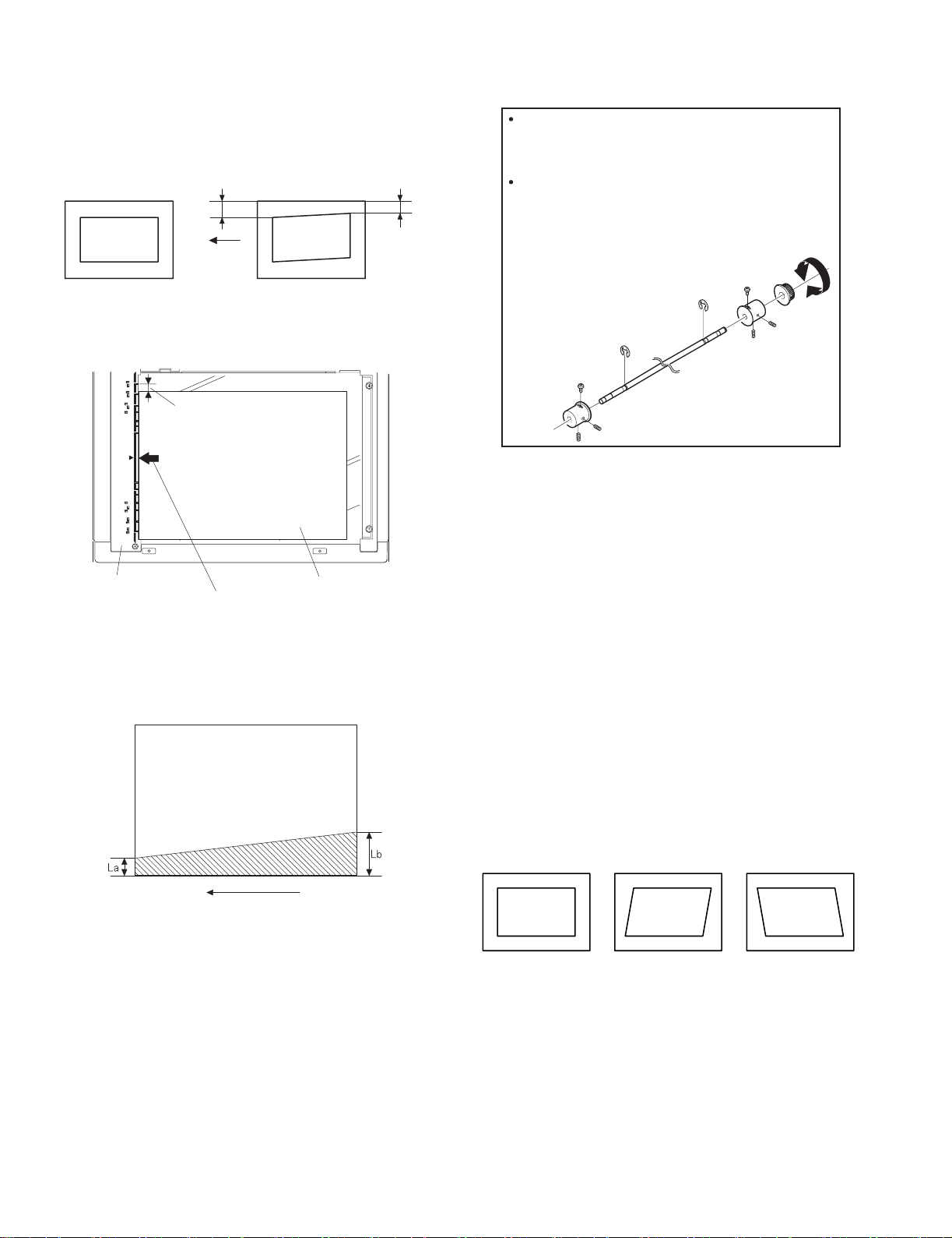
(3)Main scanning direction (FR direction) distortion
adjustment
This adjustment must be performed in the following cases:
•When the mirror base drive wire is replaced.
•When the lamp unit, or No. 2/3 mirror holder is replaced.
•When a copy as shown is made.
La
Paper exit
direction
Original
Copy
1) Set A3 (11" x 17") white paper on the original table as shown below.
Allow a little space.
Lb
4) Loosen the mirror base drive pulley fixing screw on the front frame
side or on the rear frame side.
When La < Lb
Turn the mirror base drive pulley on the front frame side in the
arrow direction A.
(Do not move the mirror base drive pulley shaft.)
When La > Lb
Turn the mirror base drive pulley on the front frame side in the
arrow direction A.
(Do not move the mirror base drive pulley shaft.)
Rear side
A
B
Front side
5)Tighten the mirror base drive pulley fixing screw.
Glass holding plate
Fit the paper edge and
the glass holding plate edge.
A3 (11" x 17") white paper
2) Open the original cover and make a normal (100%) copy.
3) Measure the width of the black background at the lead edge and at
the rear edge.
Paper exit direction
La: Lead edge black background width
Lb: Rear edge black background width
If the width (La) of the black background at the lead edge is equal that
(Lb) at the rear edge, there is no need to execute the following
procedures of 4) ~ 7).
<Adjustment specification>
La = Lb
6) Execute the main scanning direction (FR) distartion balance
adjustment previously described in 2) again.
(4) Sub scanning direction (scanning direction) distortion
adjustment
When there is no skew copy in the mirror base scanning direction and
there is no horizontal error (right angle to the scanning direction), the
adjustment can be made by adjusting the No. 2/3 mirror base unit rail
height.
Before performing this adjustment, be sure to perform the horizontal
image distortion adjustment in the laser scanner section.
This adjustment must be performed in the following cases:
•When the mirror base wire is replaced.
•When the copy lamp unit or No. 2/3 mirror unit is replaced.
•When the mirror unit rail is replaced or moved.
•When a following copy is made.
Original
Copy A Copy B
DP-1620 ADJUSTMENT 6-6
Page 28
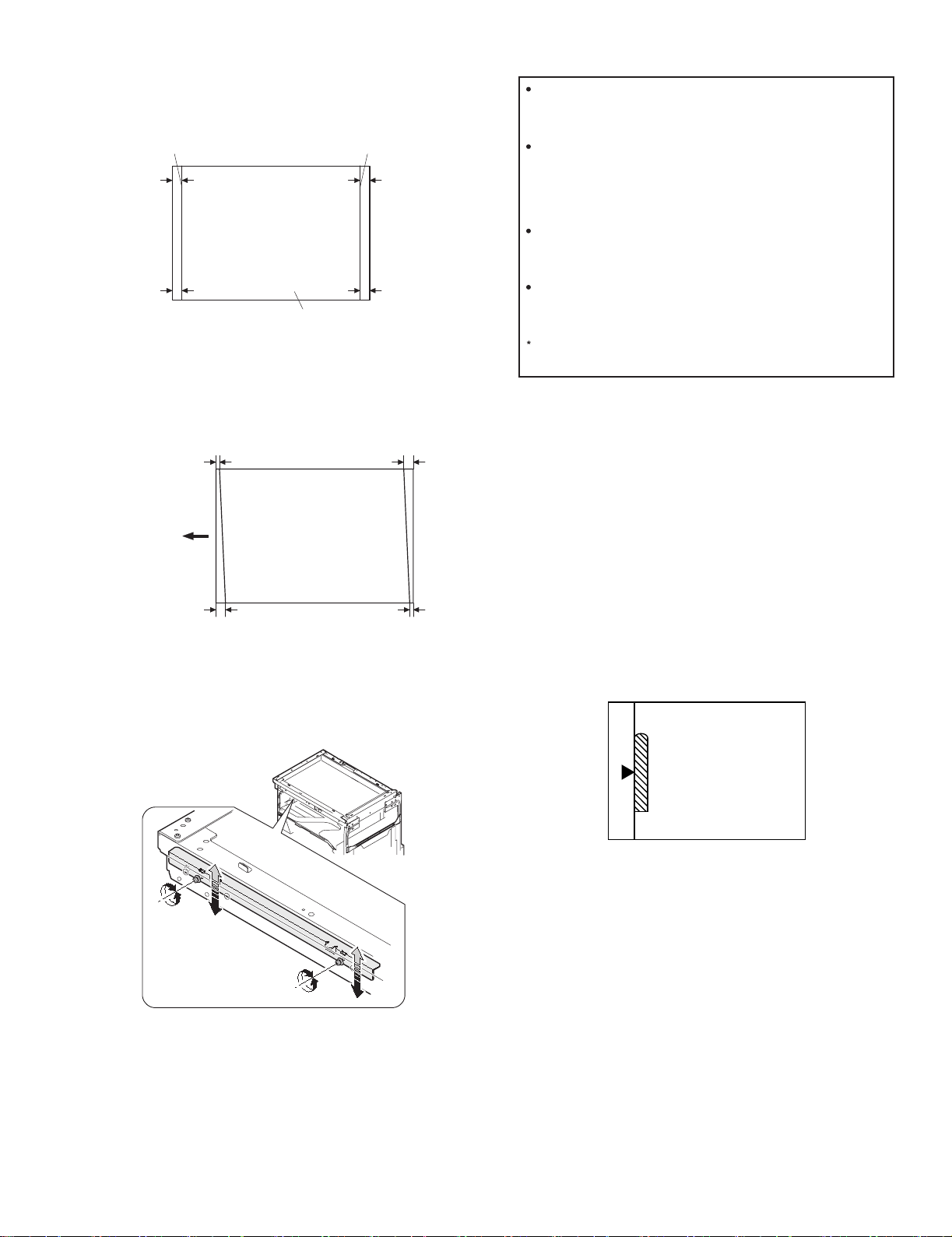
1) Making of a test sheet
Make test sheet by drawing parallel lines at 10mm from the both
ends of A3 (11" x 17") white paper as shown below. (These lines
must be correctly parallel to each other.)
When La > Lb
Shift the mirror base B rail upward by the half of the
difference of La - Lb.
Parallel line
10mm
10mm
White paper
Parallel line
10mm
10mm
2) Make a normal (100%) copy of the test sheet on A3 (11" x 17")
paper. (Fit the paper edge with the glass holding plate edge.)
3) Measure the distances (La, Lb, Lc, Ld) at the four corners as shown
below.
Paper exit
direction
La
Lb Ld
Lc
When La < Lb
Shift the mirror base B rail downward by the half of the
difference of Lb - La.
Example: When La = 12mm and Lb = 9mm, shift the mirror
base B rail upward by 1.5mm.
When Lc > Ld
Shift the mirror base B rail downward by the half of the
difference of Lc - Ld.
When Lc < Ld
Shift the mirror base B rail downward by the half of the
difference of Ld - Lc.
When moving the mirror base rail, hold the mirror base rail
with your hand.
<Adjustment specification>
La = Lb, Lc = Ld
5) After completion of adjustment, manually turn the mirror base drive
pulley, scan the mirror base A and mirror base B fully, and check that
the mirror bases are not in contact with each other.
* If the mirror base rail is moved extremely, the mirror base may be in
contact with the frame or the original glass. Be careful to avoid this.
(5) Main scanning direction (FR direction) magnification
ratio adjustment (SIM 48-1)
Note:Before performing this adjustment, be sure to check that the CCD
unit is properly installed.
When La = Lb and Lc = Ld, no need to perform the procedures 4) and 5).
4) Move the mirror base F rail position up and down (in the arrow
direction) to adjust.
Note:If the rear side rail is used for the adjustment, the scanning position
of the white balance sheet is shifted and "E7-04" may occur only
when scanning with the SPF. Therefore it is advisable to use the
front side rail for the adjustment.
1) Put a scale on the original table as shown below.
2) Execute SIM 48-1.
3) After warm-up, shading is performed and the current set value of the
main scanning direction magnification ratio is displayed on the
display section in 2 digits.
4) Select the mode and press the start key again.
5) Manual correction mode (TEXT lamp ON)
Enter the set value and press the start key.
The set value is stored and a copy is made.
DP-1620 ADJUSTMENT 6-7
Page 29
<Adjustment specification>
Note: A judgment must be made with 200mm width, and must not be
made with 100mm width.
Mode Specification SIM Set value Set range
Main scanning
direction
magnification
ratio
At normal:
±1.0%
SIM 48-1 Add 1:0.1%
increase
Reduce 1:
0.1%
1 ~ 99
decrease
(6) Sub scanning direction (scanning direction)
magnification ratio adjustment (SIM 48-1, SIM 48-5)
a. OC mode in copying (SIM48-1)
Note:Before performing this adjustment, be sure to check that the CCD
unit is properly installed.
1) Put a scale on the original table as shown below, and make a normal
(100%) copy.
2) Compare the scale image and the actual image. If necessary,
perform the following adjustment procedures.
3) Execute SIM 48-1.<<PHOTO>>
4) After warm-up, shading is performed and the current set value of the
main scanning direction magnification ratio is displayed on the
display section in 2 digits.
5) When the photo lamp is lighted by pressing the density selection key,
the current magnification ratio correction value in the sub scanning
direction is displayed in lower 2 digits of the display section.
6) Enter the set value and press the start key.
The set value is stored and a copy is made.
<Adjustment specification>
Mode Specification SIM Set value Set range
Sub scanning
direction
magnification
ratio
(OC mode)
b. RSPF sub scanning direction magnification ratio (SIM48-5)
Note:
•Before performing this adjustment, be sure to check that the CCD unit is
properly installed.
•Before performing this adjustment, the OC mode adjustment in copying
must be completed.
1) Put a scale on the original table as shown below, and make a normal
(100%) copy to make a test chart.
Normal
±1.0%
SIM 48-1
(PHOTO)
Add 1:0.1%
increase
Reduce 1:
0.1%
decrease
1 ~ 99
Note:Since the printed copy is used as a test chart, put the scale in
parallel with the edge lines.
2) Set the test chart on the SPF and make a normal (100%) copy.
3) Compare the scale image and the actual image. If necessary,
perform the following adjustment procedures.
4) Execute SIM 48-5.
5) After warm-up, shading is performed.
The auto density lamp lights up and the current front surface sub
scanning direction magnification ratio correction value is displayed in
two digits on the display section.
6) Enter the set value and press the start key.
The set value is stored and a copy is made.
7) Change the mode from the duplex original mode to the simplex
original mode.
"MANUAL" lamp lights up and the current back surface sub scanning
direction magnification ratio is displayed in two digits on the display
section.
8) Enter the set value and press the start key.
The set value is stored and a copy is made.
<Adjustment specification>
Mode Specification SIM Set value Set range
Sub scanning
direction
magnification
ratio
(SPF mode)
Normal
±1.0%
SIM 48-5 Add 1:0.1%
increase
Reduce 1:
0.1%
decrease
1 ~ 99
(7) Off center adjustment (SIM 50-12)
a. OC mode (SIM50-12)
1) Make a test chart as shown below and set it so that its center line is
fit with the original guide center mark.
* To make a test chart, draw a line on A3 or 11" x 17" paper at the
center in the paper transport direction.
Original guide
Center
Copy paper
(A3 or 17" x 11")
2) Make a normal copy from the manual paper feed tray, and compare
the copy and the test chart.
If necessary, perform the following adjustment procedures.
3) Execute SIM 50-12.
4) After warm-up, shading is performed and the current set value of the
off center adjustment is displayed on the display section in 2 digits.
5) Enter the set value and press the start key.
The set value is stored and a copy is made.
<Adjustment specification>
Mode Specification SIM Set value Set range
Original off
center mode
(OC mode)
DP-1620 ADJUSTMENT 6-8
Single:
Center ±2.0mm
SIM 50-12
(AE lamp
ON)
Add 1:
0.1mm shift
to R side
Reduce 1:
0.1mm shift
to L side
1 ~ 99
Page 30
b. SPF original off-center adjustment (SIM50-12)
Note:Before performing this adjustment, be sure to check that the paper
off center is properly adjusted.
1) Make a test chart for the center position adjustment and set it on the
SPF.
<Adjustment specification>
Draw a line on a paper in the scanning direction.
2) Make a normal copy from the manual paper feed tray, and compare
the copy and the original test chart.
If necessary, perform the following adjustment procedures.
3) Execute SIM 50-12.
4) After warm-up, shading is performed and the current set value of the
off center adjustment at each paper feed port is displayed on the
display section in 2 digits.
5) Enter the set value and press the start key.
The set value is stored and a copy is made.
<Adjustment specification>
Mode Specification SIM Set value Set
range
Original off
center
mode
(SPF mode)
Single:
Center ±3.0mm(TEXT lamp)
Duplex:
Center ±3.5mm(
PHOTO lamp
)
SIM
50-12
Add 1:
0.1mm shift
to R side
Reduce 1:
0.1mm shift
to L side
1 ~ 99
(8) SPF white correction pixel position adjustment(SIM63-7)
(required in an SPF model when replacing the lens unit)
1) Fully open the SPF.
2) Execute SIM 63-7.
3) When the operation panel displays "COMPLETE,"the adjustment is
completed.
4) If the operation panel displays "ERROR,"perform the following
measures.
•When the display is 0:
Check that the SPF is open.
Check that the lamp is ON.(If the lamp is OFF,check the MCU connector.)
Check that the CCD harness is properly inserted into the MCU
connector.
•When the display is 281 or above:
1) Remove the table glass.
2) Remove the dark box.
3) Slide the lens unit toward the front side and attach it,then execute
SIM.
•When the display is 143 or below:
1) Remove the table glass.
2) Remove the dark box.
3) Slide the lens unit toward the rear side and attach it,then execute
SIM.
C.Image density adjustment
(1)Copy mode (SIM 46-1)
1)Set a test chart on the OC table as shown below.
2) Put several sheets of A3 or 11" x 17" white paper on the test chart.
3) Execute SIM 46-1.
4) After warm-up, shading is performed and the current set value of the
density level is displayed on the display section in 2 digits.
For mode selection, use the density select key.
5) Change the set value with the 10-key to adjust the copy image
density.
6) Make a copy and check that the specification below is satisfied.
<Adjustment specification>
Density
mode
Auto Auto - "2" is slightly
Text Text 3 "3" is slightly
Photo Photo 3 "2" is slightly
Toner
save
Toner
save
Display
lamp
Text/
Photo
Auto/
Photo
Exposure
level
Sharp Gray
Chart output
copied.
copied.
copied.
3 "3" is slightly
copied
- "2" is slightly
copied
Set value Set
The greater the
set value is the
greater the
density is The
smaller the set
value is the
smaller the
density is.
range
1 ~ 99
F
* When the lens unit is moved,execute the OC main scanning
magnification ratio auto adjustment,SIM 48-1-1,IM48-3 and the PF
original off-center adjustment.
* This adjustment is basically O.K.with IM 63-7.
R
DP-1620 ADJUSTMENT 6-9
Page 31

[7] SIMULATIONS
1. Entering the simulation mode
The initial "C" key AUTO/TEXT/PHOTO key "C" key
AUTO/TEXT/PHOTO key sequence must be performed quickly with
no more than a second between key strokes.
Main code Start key Sub code Start key.
2. Canceling the simulation mode
When the clear all key is pressed, the simulation mode is cancelled.
When the interruption key is pressed, the process is interrupted and the
screen returns to the sub code entering display.
* After canceling the simulation mode, be sure to turn OFF/ON the
power and check the operation.
Note: If the machine is terminated by a jam error or paper empty during
copying in the adjustment by the simulation, recopying is required.
3. List of simulations
Main
Sub
code
code
01 01 Mirror scanning operation
02 Mirror home position sensor (MHPS) status display
06 Mirror scanning operation aging
02 01 Single paper feeder (SPF) aging
02 SPF sensor status display
03 SPF motor operation check
08 SPG paper feed solenoid operation check
11 SPF PS release solenoid operation check
05 01 Operation panel display check
02 Fusing lamp and cooling fan operation check
03 Copy lamp lighting check
06 01 Paper feed solenoid operation check
02 Resist roller solenoid operation check
10 Cassette semi-circular roller cleaning
07 01 Warm-up display and aging with jam
06 Intermittent aging
08 Shifting with warm-up display
08 01 Developing bias output
02 Main charger output (Grid = HIGH)
03 Main charger output (Grid = LOW)
06 Transfer charger output
10 - Toner motor operation
14 - Trouble cancel (except for U2)
16 - U2 trouble cancel
20 01 Maintenance counter clear
21 01 Maintenance cycle setting
02 Mini maintenance cycle setting
22 01 Maintenance counter display
02 Maintenance preset display
03 Jam memory display
04 Jam total counter display
05 Total counter display
06 Developing counter display
07 Mini maintenance preset display
08 SPF counter display
09 Paper feed counter display
12 Drum counter display
13 CRUM type display
14 P-ROM version display
15 Trouble memory display
17 Copy counter display
18 Printer counter display
21 Scanner counter display
22 SPF jam counter display
Contents
Main
code
Sub
code
24 01 Jam total counter clear
02 Trouble memory clear
04 SPF counter clear
06 Paper feed counter clear
07 Drum counter clear
08 Copy counter clear
09 Printer counter clear
13 Scanner counter clear
14 SPF jam total counter clear
15 Scanner mode counter clear
25 01 Main motor operation check
10 Polygon motor operation check
26 02 Size setting
05 Count mode setting
06 Destination setting
07 Machine condition check (CPM)
18 Toner save mode setting
30 CE mark conformity control ON/OFF
36 Cancel of stop at maintenance life over
37 Cancel of stop at developer life over
38 Cancel of stop at drum life over
39 Memory capacity check
42 Transfer ON/OFF timing control setting
43 Side void amount setting
51 Copy temporary stop function setting
30 01 Paper sensor status display
42 01 Developing counter clear
43 01 Fusing temperature setting
12 Standby mode fusing fan rotation setting
13 Fusing paper interval control allow/inhibit setting
44 34 Transfer current setting
40 Setting of rotation time before toner supply
46 01 Copy density adjustment (300dpi)
02 Copy density adjustment (600dpi)
09 Copy exposure level adjustment, individual setting
(Text) 300dpi
10 Copy exposure level adjustment, individual setting
(Text) 600dpi
11 Copy exposure level adjustment, individual setting
(Photo) 600dpi
18 Image contrast adjustment (300dpi)
19 Exposure mode setting
(Gamma table setting/AE operation mode setting/
Photo image process setting)
20 SPF exposure correction
29 Image contrast adjustment (600dpi)
30 AE limit setting
31 Image sharpness adjustment
48 01 Main/sub scanning magnification ratio adjustment
05 SPF/RSPF mode sub scanning magnification ratio
adjustment in copying
49 01 Flash ROM program writing mode
12 Standby mode fusing fan RPM setting
50 01 Image lead edge adjustment
06 Copy lead edge position adjustment (SPF/RSPF)
10 Paper off-center adjustment
12 Document off-center adjustment
51 02 Resist amount adjustment
53 08 SPF scanning position automatic adjustment
61 03 HSYNC output check
63 01 Shading check
07 SPF automatic correction
64 01 Self print
Contents
DP-1620 SIMULATIONS 7-1
Page 32

4. Contents of simulations
Main
Sub
code
code
01 01 Mirror scanning operation When the [START] key is pressed, the home position is checked in the first place, and the mirror
02 Mirror home position sensor
(MHPS) status display
06 Mirror scanning operation aging When the [START] key is pressed, the mirror base performs A3 full scanning at the set magnification
02 01 Single paper feeder (SPF) aging When the [START] key is pressed, the set magnification ratio is acquired and document transport
02 SPF sensor status display (In order to receive the sensor change notification, the load must be decreased.)
03 SPF motor operation check When the [START] key is pressed, the motor rotates for 10 sec at the speed corresponding to the set
08 SPG paper feed solenoid
operation check
11 SPF PS release solenoid operation
check
Contents Details of operation
base performs A3 full scanning once at the set magnification ratio speed. During this scanning, the
set magnification ratio is displayed. The mirror home position sensor status is displayed with the
photoconductor cartridge replacement lamp.
(The lamp lights up when the mirror is in the home position.)
During scanning, the copy lamp lights up.
When the [Interrupt] key is pressed, the operation is interrupted to go to the sub code input standby
mode.
Used to monitor the mirror home position sensor. When the sensor is ON, the photoconductor
cartridge replacement lamp is lighted. During that time, the display section displays the sub code.
When the [Interrupt] key is pressed, the machine goes to the sub code input standby mode.
(When the CA key is pressed, the simulation is terminated.)
ratio speed. During scanning, the set magnification ratio is displayed. After 3 seconds, the mirror
base performs full scanning again. During scanning, the set magnification ratio is displayed.
* When the [START] key is pressed again, the ready lamp turns and remains off.
The DV replacement/OPC drum cartridge replacement lamp displays the status of the mirror
home position sensor. (The lamp lights up when the mirror is in the home position.)
During aging, the copy lamp lights up. When the [Interrupt] key is pressed, the operation is
interrupted if operating, and the machine goes into the sub code input standby mode.
operation of single surface is performed in the case of SPF or document transport operation of
duplex surfaces is performed. During operation, the LED on the display section corresponding to the
selected magnification ratio lights up, and the magnification ratio is displayed on the 7-seg display.
When the [Interrupt] key is pressed at that time, the machine goes to the sub code input standby
mode. When the [CA] key is pressed, the simulation is terminated.
The sensor status (ON/OFF) in the SPF can be checked with the following lamps.
When a sensor detects paper, it turns on. The open/close detection sensor turns on when the
machine is opened.
Display lamp Sensor
Toner supply lamp
Copier jam lamp
The DV replacement/OPC drum cartridge
replacement lamp
Paper empty lamp
SPF jam lamp
Manual paper feed lamp
Tray jam lamp
AE lamp
TEXT lamp
PHOTO lamp
When the [Interrupt] key is pressed, the machine goes to the sub code input standby mode.
When the [CA] key is pressed, the simulation is terminated.
magnification ratio. When the [Interrupt] key is pressed, the machine stops operation and goes to the
sub code input standby mode. When the [CA] key is pressed, the simulation is terminated.
The SPF paper feed solenoid (PSOL) is turned ON for 500msec and OFF for 500msec.
This operation is repeated 20 times.
After completion of the process, the machine goes to the sub code input standby mode.
When the [Interrupt] key is pressed during the process, the machine goes to the sub code input
standby mode. When the [CA] key is pressed, the simulation is terminated.
The SPF PS release solenoid (CLH) is turned ON for 500msec and OFF for 500msec. This operation
is repeated 20 times.
After completion of the process, the machine goes to the sub code input standby mode. When the
[Interrupt] key is pressed during the process, the machine goes to the sub code input standby mode.
When the [CA] key is pressed, the simulation is terminated.
SPF document set sensor
SPF document transport sensor
SPF unit (OC cover) open/close sensor
SPF paper exit sensor
SPF paper feed cover open/close sensor
SPF paper length sensor 1
SPF paper length sensor 2
SPF paper feed width sensor (small)
SPF paper feed width sensor (middle)
SPF paper feed width sensor (large)
DP-1620 SIMULATIONS 7-2
Page 33

Main
code
Sub
code
Contents Details of operation
05 01 Operation panel display check <<LED check mode (ALL ON/Individual ON)>>
When the [START] key is pressed in the sub code input mode, all the LED's (including the 7-seg
lamps) are turned ON. After 5 sec of all ON, the machine goes to the sub code input standby mode.
When the [Mode select] key is pressed during all ON, the lighting mode is shifted to the individual ON
mode, where the LED's are individually lighted from the left top, to the left bottom, to the next line top,
to the bottom, and so on. (For the 7-seg lamps, the 3-digit lamps are lighted at once.)
After completion of lighting of all the lamps, the mode is shifted to the all ON mode.
After 5 sec of all ON mode, the machine goes to the sub code input standby mode.
Individual ON mode cycle: 300ms for ON 20ms for OFF
When the [Interrupt] key is pressed in the LCD check mode, the machine goes back to the sub code
input standby mode.
When the [CA] key is pressed, the simulation is terminated.
When the [START] key is pressed with all the lamps ON, the machine goes back to the key input
check mode.
<< Key input check mode>>
When the machine goes into the key input check mode, [- - -] is displayed on the copy quantity
display. Every time when a key on the operation panel is pressed, the input value is added on the
copy quantity display.
[- - -] [ 1] [ 2] •••.
When a key is pressed once, it is not counted again.
When the [START] key is pressed, the input number is added and displayed for 3 sec, and the
machine goes into the LED lighting check mode (LED all ON state). When the [Interrupt] key is
pressed for the first time, it is counted. When the key is pressed for the second time, the machine
goes into the sub code input mode. When the [CA] key is pressed for the first time, it is counted.
When the key is pressed for the second time, the simulation is terminated. (Note for the key input
check mode).
•Press the [START] key at the end. (When the key is pressed during the process, the machine goes
into the LED lighting check mode (all ON state).).
•When two or more keys are pressed simultaneously, they are ignored.
02 Fusing lamp and cooling fan
operation check
When the [START] key is pressed, the fusing lamp turns ON for 500ms and OFF for 500ms.
The operation is repeated 5 times. During this process, the cooling fan motor rotates.
After completion of the process, the machine goes into the sub code input standby mode.
03 Copy lamp lighting check When the [START] key is pressed, the copy lamp lights up for 5 sec. After completion of lighting, the
machine goes into the sub code input mode.
When the [Interrupt] key is pressed, the process is interrupted and the machine goes into the sub
code input standby mode. When the [CA] key is pressed, the simulation is terminated.
06 01 Paper feed solenoid operation
check
When this simulation is executed, the sub code is displayed on the 7-seg LED and the lamp
corresponding to the solenoid lights up.
Select a solenoid with the tray select key (the lamp corresponding to the solenoid lights up) and
press the [START] key, and the machine repeats operation of ON for 500ms and OFF for 500ms.
This operation is repeated 20 times.
After that, the machine goes into the sub code entry standby mode.
When [INTERRUPT] key is pressed during the process, the machine goes into the sub code input
standby mode. When [CA] key is pressed, the simulation is terminated.
Display lamp Solenoid
Main cassette lamp
2nd cassette lamp
Manual paper feed lamp
2nd cassette jam lamp
Main cassette paper feed solenoid
* 2nd cassette paper feed solenoid
Manual paper feed solenoid
* 2nd cassette paper transport solenoid
* Supported for the installed models only. Skipped for the models without installation.
02 Resist roller solenoid operation
check
When the [START] key is pressed in the sub code input state, the resist solenoid (RRS) turns ON for
500ms and OFF for 500ms. This operation is repeated 20 times.
After completion of the process, the machine goes into the sub code input standby mode.
When [INTERRUPT] key is pressed during the process, the machine goes into the sub code input
standby mode. When [CA] key is pressed, the simulation is terminated.
10 Cassette semi-circular roller
cleaning
First of all, remove the developer unit.
Enter the simulation code, specify the cassette to be cleaned with the tray select key, and press
START button. The main motor rotates to move the cassette semi-circular roller by half circle and
make the roller face downward.
After completion of cleaning, when INTERRUPT key is pressed, the machine goes into the sub code
entry standby mode and the roller returns to the original positions.
To clean another roller continuously, press INTERRUPT key to return the roller to the original
position, and execute the simulation again.
During the operation, the sub code is displayed on the display.
* When CA key is pressed, the simulation mode is terminated.
However, the roller returns to the original position by the initial operation.
DP-1620 SIMULATIONS 7-3
Page 34

Main
Sub
code
code
07 01 Warm-up display and aging with
jam
Contents Details of operation
Copying is repeated to make the set copy quantity. When this simulation is executed, warm-up is
started and warm-up time is counted up every second from 0 and displayed. After completion of
warm-up, warm-up time count is stopped. When the [CA] key is pressed, the ready lamp lights up.
After that, when the copy quantity is inputted with keys and the [START] key is pressed, copying is
repeated to make the set copy quantity. (Intermittent 0 sec)This simulation is canceled by turning off
the power or performing a simulation that executes hardware reset.
06 Intermittent aging Copying is repeated to make the set copy quantity. When this simulation is performed, warm-up is
performed and the ready lamp is lighted. Enter the copy quantity with the key and press the [START]
key, and copying is repeated to make the set copy quantity, the ready state remains for 3 sec, and
copying is repeated again to make the set copy quantity. These operations are repeated.
This simulation is canceled by turning off the power or performing a simulation that executes
hardware reset.
08 Shifting with warm-up display
(Shifting similar to pressing the CA
key)
When the simulation code is entered, warm-up is started and warm-up time is counted up every
second from 0 and displayed. When the [CA] key is pressed during counting up, the display section
displays "0" and count-up process stops. However, warm-up is continued.
After completion of warm-up, counting is stopped. Press the [CA] key to terminate the simulation
mode. (This simulation is similar to SIM07-01, but without the aging function.)
08 01 Developing bias output When the [START] key is pressed, the developing bias signal is turned ON for 30 sec.
However, to calculate the actual output value is calculated, execute SIM25-01.
After completion of the process, the machine goes into the sub code input standby mode.
When [INTERRUPT] key is pressed during the process, the machine goes into the sub code input
standby mode. When [CA] key is pressed, the simulation is terminated.
02 Main charger output (Grid = HIGH) When the [START] key is pressed, the main charger output is supplied for 30 sec in the grid voltage
HIGH mode. After completion of the process, the machine goes into the sub code input standby
mode.
When [INTERRUPT] key is pressed during the process, the machine goes into the sub code input
standby mode. When [CA] key is pressed, the simulation is terminated.
03 Main charger output (Grid = LOW) When the [START] key is pressed, the main charger output is supplied for 30 sec in the grid voltage
LOW mode. After completion of the process, the machine goes into the sub code input standby
mode.
When [INTERRUPT] key is pressed during the process, the machine goes into the sub code input
standby mode. When [CA] key is pressed, the simulation is terminated.
06 Transfer charger output Select an output mode with the [Mode select] key and press the [START] key. The transfer charger
output is delivered for 30 sec in the selected mode.
After 30 sec of transfer charger output, the machine goes into the sub code entry standby mode.
When [INTERRUPT] key is pressed during the process, the machine goes into the sub code input
standby mode. When [CA] key is pressed, the simulation is terminated.
Display lamp Output mode
AE mode lamp
AE mode lamp & PHOTO mode lamp
AE & TEXT & PHOTO mode lamp
Normal size width: Front surface
Small size width: Front surface
Manual paper feed mode
•Small size is Letter R (A4R) or smaller.
10 - Toner motor operation When the [START] key is pressed, the toner motor is driven for 30 sec.
After completion of the process, the machine goes into the main code input standby mode.
When the [Interrupt] key is pressed, the machine goes into the main code input standby mode.
14 - Trouble cancel (except for U2) * Trouble to write into the EEPROM such as H trouble is canceled and hardware reset is
performed.
16 - U2 trouble cancel * U2 trouble is canceled and hardware reset is performed.
20 01 Maintenance counter clear When the [Start] key is pressed, the maintenance count value is cleared and "000000" is displayed.
(Alternate display of "000" and "000")
21 01 Maintenance cycle setting The current set maintenance cycle code is displayed (initial display), and the set data are stored.
Code Setting
02 Mini maintenance cycle setting
(Valid only when the destination is
set to Japan AB series.)
0
1
2
3
4
5
The current set maintenance cycle code is displayed (initial display), and the set data are stored.
Code Setting
0
1
2
5,000 sheets
7,500 sheets
10,000 sheets
25,000 sheets
50,000 sheets * Default
Free (999,999 sheets)
5,000 sheets * Default
10,000 sheets
Free (999,999 sheets)
DP-1620 SIMULATIONS 7-4
Page 35

Main
code
Sub
code
Contents Details of operation
22 01 Maintenance counter display The maintenance counter value is displayed. (Alternate display by 3 digits)
02 Maintenance preset display (Valid
only when the destination is set to
The copy quantity corresponding to the code that is set with SIM21-01 is displayed.
(For example: 50,000 sheets)
EX Japan)
03 Jam memory display The LED of the latest jam position is lighted. Every time when the magnification ratio display key is
pressed, the jam memory data is acquired sequentially from the latest. The jam position is judged by
the acquired data and the corresponding LED is lighted. The 7-seg display indicates the jam number.
At that time, "A" is displayed on the upper first digit. When the last one is displayed, the latest one will
be displayed again. Max. 30 jams from the latest are stored. When the [Interrupt] key is pressed, the
machine goes into the sub code input standby mode. When the [CA] key is pressed, the simulation is
terminated.
04 Jam total counter display The jam total counter value is displayed. (Alternate display by 3 digits)
05 Total counter display The total counter value is displayed. (Alternate display by 3 digits)
06 Developing counter display The developing counter data is acquired and displayed on the 7-seg display. (Alternate display by 3
digits)
When the [Interrupt] key is pressed, the machine goes into the sub code input standby mode.
When the [CA] key is pressed, the simulation is terminated.
07 Mini maintenance preset display
(Valid only when the destination is
set to Japan AB series)
The mini maintenance cycle data is acquired and displayed on the 7-seg display.
When the [Interrupt] key is pressed, the machine goes into the sub code input standby mode.
When the [CA] key is pressed, the simulation is terminated.
08 SPF counter display The SPF counter value is displayed. (Alternate display by 3 digits)
09 Paper feed counter display The counter value of the selected paper feed section is acquired from each variable, the data is
displayed on the 7-seg display according to the regulations. When this simulation is executed, the
value of the first cassette is displayed first. Press the tray select key to select the paper feed tray.
When the [Interrupt] key is pressed, the machine goes into the sub code input standby mode.
When the [CA] key is pressed, the simulation is terminated.
12 Drum counter display The drum counter and the drum rotating time are displayed.
To change the display mode, press the [Mode select] key.
Display lamp
AE mode lamp
TEXT mode lamp
Display mode
Drum counter
Drum rotating time
13 CRUM destination display When this simulation is executed, the CRUM destination set (written) in the CRUM chip is displayed.
This simulation is valid only for the models where the CRUM is valid.
7-seg display Meaning (CRUM destination) 7-seg display Meaning (CRUM destination)
00
01
02
03
Not set yet
BTA-A
BTA-B
BTA-C
04
99
12
BTA-E
Conversion
AL series
14 P-ROM version display The P-ROM version is displayed on the copy quantity display. The main code and the sub code are
alternatively displayed by 2 digits. The display interval is same as that of the counter display.
By pressing the fixed magnification ratio key, each version display is switched.
Display lamp (AB series) Display lamp (Inch series) Displayed version
141% 141% Machine program
15 Trouble memory display The trouble codes up to the latest one are acquired from the trouble memory data.
Every time when the magnification ratio display is pressed, the main code of the trouble is displayed
on the 1st ~ 2nd digit.
* The latest 20 troubles are stored in the memory.
The 3rd digit indicates the trouble history code, "A" ~ "J" (meaning of 1 ~ 10).
After "J" is displayed, "A" ~ "J" blinks. (Meaning of 11 ~ 20)
After "J" blinks (meaning of 20), "A" ~ "J" is lighted. (Returns to 1.)
When the [START] key is pressed, the sub code is displayed.
When the [Interrupt] key is pressed, the machine goes into the sub code input standby mode.
When the [CA] key is pressed, the simulation is terminated.
* Note that when the history code blinks, the trouble code and the sub code do not blink.
17 Copy counter display The copy counter value is displayed. (Alternate display by 3 digits) When the [Interrupt] key is
pressed, the machine goes into the sub code input standby mode. When the [CA] key is pressed, the
simulation is terminated.
18 Printer counter display The printer counter value is displayed. (Alternate display by 3 digits)When the [Interrupt] key is
pressed, the machine goes into the sub code input standby mode. When the [CA] key is pressed, the
simulation is terminated.
21 Scanner counter display The scanner counter value is displayed. (Alternate display by 3 digits)When the [Interrupt] key is
pressed, the machine goes into the sub code input standby mode. When the [CA] key is pressed, the
simulation is terminated.
DP-1620 SIMULATIONS 7-5
Page 36

Main
code
Sub
code
Contents Details of operation
22 22 SPF jam counter display The SPF jam counter value is displayed. (Alternate display by 3 digits)When the [Interrupt] key is
pressed, the machine goes into the sub code input standby mode. When the [CA] key is pressed, the
simulation is terminated.
24 01 Jam total counter clear When the [START] key is pressed, the jam total count value is reset to zero, and zero is displayed.
02 Trouble memory clear The trouble memory and the EEPROM trouble history data are cleared and "000" is displayed on the
7-seg display. When the [Interrupt] key is pressed, the machine goes into the sub code input standby
mode. When the [CA] key is pressed, the simulation is terminated.
04 SPF counter clear When the [START] key is pressed, the SPF count value is reset to zero and displayed on the 7-seg
display. When the [Interrupt] key is pressed, the machine goes into the sub code input standby mode.
When the [CA] key is pressed, the simulation is terminated.
06 Paper feed counter clear The paper feed counter data of each paper feed section is cleared, and "000" is displayed on the 7-
seg display. When the [Interrupt] key is pressed, the machine goes into the sub code input standby
mode. When the [CA] key is pressed, the simulation is terminated.
07 Drum counter clear When the [START] key is pressed, the drum count and the drum roasting time are reset to zero, and
the drum counter value is displayed on the 7-seg LED. When the [Interrupt] key is pressed, the
machine goes into the sub code input standby mode. When the [CA] key is pressed, the simulation is
terminated.
08 Copy counter clear When the [START] key is pressed, the copy count value is reset to zero and displayed on the 7-seg
display. When the [Interrupt] key is pressed, the machine goes into the sub code input standby mode.
When the [CA] key is pressed, the simulation is terminated.
09 Printer counter clear When the [START] key is pressed, the printer count value is reset to zero and displayed on the 7-seg
display. When the [Interrupt] key is pressed, the machine goes into the sub code input standby mode.
When the [CA] key is pressed, the simulation is terminated.
13 Scanner counter clear When the [START] key is pressed, the scanner count value is reset to zero and displayed on the 7-
seg display. When the [Interrupt] key is pressed, the machine goes into the sub code input standby
mode. When the [CA] key is pressed, the simulation is terminated.
14 SPF jam total counter clear When the [START] key is pressed, the SPF jam total count value is reset to zero and displayed on the
7-seg display. When the [Interrupt] key is pressed, the machine goes into the sub code input standby
mode. When the [CA] key is pressed, the simulation is terminated.
15 Scanner mode counter clear When the [START] key is pressed, the scanner mode count value is reset to zero and displayed on
the 7-seg display. When the [Interrupt] key is pressed, the machine goes into the sub code input
standby mode. When the [CA] key is pressed, the simulation is terminated.
25 01 Main motor operation check
(Cooling fan motor rotation check)
When the [START] key is pressed, the main motor (together with the duplex motor for the duplex
model) is driven for 30 sec. At that time, to save toner consumption, if the developing until is installed,
the developing bias, the main charger, and the grid are outputted. Since, in that case, laser discharge
is required when the motor stops, the polygon motor is driven simultaneously. Check if the
developing unit is installed or not. If it is not installed, the above high voltage is not outputted and only
the motor is rotated. After completion of 30 sec operation, the machine goes into the sub code input
standby mode.
* This simulation must not be executed by forcibly turning on the door open/close switch.
10 Polygon motor operation check When the [START] key is pressed, the polygon motor is rotated for 30 sec. After completion of 30 sec
operation, the machine goes into the sub code input standby mode.
26 02 Size setting Used to set Enable/Disable of the FC (8.5" x 13") size detection.
Code number Setting
0
1
FC detection Disable
FC detection Enable
* Default except for the following
* Default only for SCA/Philippines
Detection size when a document of the FC ((8.5" x 13") size is used
Unit to
be used
Destination Document size
Document SPF EX Japan AB
series (FC)
0 (Disable) 1 (Enable)
FC (8.5" x 13") B4 FC (8.5" x 13")
B4 B4 FC (8.5" x 13")
Setting
Inch series (FC) FC (8.5" x 13") LG (8.5" x 14") FC (8.5" x 13")
LG (8.5" x 14") LG (8.5" x 14") FC (8.5" x 13")
•For the other destinations, this setting is disabled.
DP-1620 SIMULATIONS 7-6
Page 37

Main
Sub
code
code
26 05 Count mode setting When any key input is made, it is displayed on the display section. When the [START] key is pressed,
06 Destination setting When this simulation is executed, the current set destination code number is displayed. Enter the
07 Machine condition check (CPM) When this simulation is executed, the current setting of the machine is displayed.
Contents Details of operation
the set code data are acquired and stored to the count mode set variable and in the EEPROM, and
the machine goes into the sub code input standby mode. However, if the [START] key is pressed
outside the set range, it is not assured. At that time, when the [Interrupt] key is pressed, the data are
not rewritten and the machine goes into the sub code input standby mode. When the [CA] key is
pressed, the simulation is terminated without rewriting the data.
[*1 : Total counter / Developer counter *2 : maintenance counter]
0:
1:
2:
3:
desired code number of the destination and press the [START] key to set the destination.
If this setting is changed, SIM46-19 setting is also changed accordingly.
(The paper size is also changed: AB series is changed to A4, and Inch series to Letter.
The AE limit setup is set to the default.
When the destination is changed (from Japan to EX Japan or from EX Japan to Japan),
the maintenance cycle is also set to the default accordingly.)
*1= Double count
*1= Single count
*1= Double count
*1= Single count
Code number Destination
0
1
2
3
4
5
6
7-seg display Meaning (CPM information)
15
16
20
Japan AB series
Inch series
EX Japan AB series
EX Japan inch series
EX Japan AB series (FC)
China (EX Japan AB series + China paper support)
Taiwan (EX Japan AB series + China paper support)
15CPM
16CPM
20CPM
*2= Double count
*2 = Double count
*2= Single count
*2= Single count
18 Toner save mode setting Used to set ON/OFF of the toner save mode.
Code number Setting
0
1
* The toner save mode of the user program is also changed accordingly.
30 CE mark conformity control ON/
OFF
36 Cancel of stop at maintenance life
over
37 Cancel of stop at developer life
over
38 Cancel of stop at drum life over When this simulation is executed, the current set code number is displayed. Enter the desired code
When this simulation is executed, the current set code number of CE mark conformity is displayed.
Enter the desired code number of CE mark conformity and press the [START] key to set the code
number.
Code number Setting
0
1
Used to set stop at maintenance life over.
Code number Setting
0
1
When this simulation is executed, the current set code number is displayed. Enter the desired code
number and press the [START] key to set the code number. The machine goes into the sub code
input state.
Code number Setting
0
1
number and press the [START] key to set the code number.
Code number Setting
0
1
To n er save OF F
To n er save ON
CE mark conformity control OFF *Default for 100V system
CE mark conformity control ON
Stop at maintenance life over
Cancel of stop at maintenance life over * Default
Stop at developer life over
Cancel of stop at developer life over
Stop at drum life over
Cancel of stop at drum life over
DP-1620 SIMULATIONS 7-7
Page 38

Main
code
Sub
code
Contents Details of operation
26 39 Memory capacity check When this simulation is executed, the current memory capacity is displayed.
7-seg display Meaning (Memory capacity)
42 Transfer ON/OFF timing control
setting
16
32
When this simulation is executed, the current setting value of transfer ON timing is displayed.
Enter a set value and press the [START] key to set the entered value, and the machine will go into
16MByte
32MByte
the sub code input standby mode.
When the [Mode select] key is pressed, the ON timing setting and the OFF timing setting are
alternatively selected. At that time, the setting is saved and written into the EEPROM.
Display lamp Setting mode Default
AE mode lamp
TEXT mode lamp
Transfer ON timing
Transfer OFF timing
•Setting range: 1 ~ 99
When the setting value is increased by 1, time is increased by 2ms.
•The default, 50, of transfer ON timing means "344ms passed from PS release."
The default, 50, of transfer OFF timing means "304ms passed from P-IN OFF."
43 Side void amount setting Used to set the side void amount on the both sides.
Enter a set value with the 10-key and press the [START] key, and the entered value will be saved and
the machine will go into the sub code input standby mode.
The setting range is 0 ~ 10. When the set value is increased by 1, the void amount is increased by
0.5mm. The default is 3 (= 1.5mm).
To select the setting mode, press the [Exposure mode select] key. The set value of the selected
mode is displayed on the copy quantity display. At that time, the set value is also saved.
Display lamp Setting mode
AE mode lamp
TEXT mode lamp
Side void amount (Right)
Side void amount (Left)
* When the setting value is increased by 1, time is increased by 0.5ms.
51 Copy temporary stop function
setting
When any key is pressed, it is displayed on the display section. When the [START] key is pressed,
the set code data is acquired and stored to the setting variable of sort/group copy temporary stop
function and to the EEPROM. The machine goes into the sub code input standby mode.
Code number Setting
0
1
Not stop
Stop * Default
When the [Interrupt] key is pressed at that time, the machine goes into the sub code input standby
mode without rewriting the data. When the [CA] key is pressed, the simulation mode is terminated
without rewriting the data.
* When this is set to "Stop," temporary stop is made for every 250 copies in one copy job.
30 01 Paper sensor status display The paper sensor status is displayed with the lamps on the operation panel.
* When each sensor detects paper, the corresponding lamp turns on.
Display lamp Sensor name
Developer lamp
Machine jam lamp
Toner lamp
Manual paper feed lamp
No. 1 cassette lamp
No. 2 cassette lamp
Tray jam lamp 1
Paper exit sensor
Duplex sensor
Paper entry sensor
Manual feed paper empty sensor
No. 1 tray paper empty sensor
No. 2 tray paper empty sensor
No. 2 tray paper feed sensor
50
50
42 01 Developing counter clear The developer counter data in the EEPROM is cleared and 0 is displayed on the 7-seg display.
When the [Interrupt] key is pressed at that time, the machine goes into the sub code input standby
mode. When the [CA] key is pressed, the simulation mode is terminated.
DP-1620 SIMULATIONS 7-8
Page 39

Main
code
Sub
code
Contents Details of operation
43 01 Fusing temperature setting
(During normal copy)
When the simulation is terminated, the current set value is displayed. When the [%] key is pressed,
the setting is changed. When the [START] key is pressed, the set content is written into the EEPROM
and the machine goes into the sub code input standby mode.
Set temperature (°C) Set temperature (°C)
160
165
170 * Default
175
185
190
195
200
180
12 Standby mode fusing fan rotation
setting
When this simulation is executed, the current set code number is displayed. Enter the desired code
number and press the [START] key to set the code number.
Code number Setting
13 Fusing paper interval control allow/
inhibit setting
0
1
Used to set the paper feed timing of 21st and later page to A3 or WLT when multi copying or printing
paper of narrow width. (A3 or WLT depends on the destination.)
Low speed rotation *Default
High speed rotation
When this simulation is executed, the currently set code number is displayed. Enter a desired code
number and press the [START] key, and the entered code number is written into the EEPROM and
the machine goes into the sub code entry standby mode.
Code number Setting
0
1
Inhibit * Default
Allow
<Applicable paper>
1) Cassette paper feed: A4R, B5R, 8-1/2" X 14", 8-1/2" X 13", 8-1/2" X 11", A5, INV
2) Manual paper feed: A4R, B5R, 8-1/2" X 14", 8-1/2" X 13", 8-1/2" X 11", A5, INV,16KR
* A5 size for manual paper feed is valid only for EX Japan AB series.
44 34 Transfer current setting Used to set the transfer current for the front surface and that for the back surface. When this
simulation is executed, the current set value is displayed on the 7-seg display. Select the set value
with the zoom (Up/Down) keys and press the [START] key, and the set content is written into the
EEPROM and the machine goes into the sub code input standby mode. Press the [Mode select] key
to select each setting mode. At that time, the setup content is written into the EEPROM.
The set range is 90uA ~ 360uA in the increment of 10uA.
Display lamp Setting mode
AE mode lamp
AE mode lamp & PHOTO mode lamp
AE & TEXT & PHOTO mode lamps
Normal size width: Front
Small size width: Front
Manual paper feed
* Small size paper must be Letter R (A4R) or smaller.
* For the special size of tray, use the normal size width.
40 Setting of rotation time before
toner supply
Used to set the time interval between start of rotation (ready) of the main motor and start of toner
supply in previous rotation after supplying the power. [1] ~ [99] (Default [8], unit: sec)
46 01 Copy density adjustment (300dpi) Used to set the copy density for each mode.
(Operating procedure)
When this simulation is executed, warm-up and shading are operated, and the current set value is
displayed in two digits. (Default [50])
* The density LED is not lighted.
Change the set value and press the [START] key, and a copy is made according to the set value.
The greater the set value is, the darker the density is, and vise versa. In this case, only a copy at Exp.
3 can be made. When, however, the density is set darker, Exp.1 and Exp. 5 become darker, too.
If the dentistry is set lighter, Exp. 1 and Exp. 5 become lighter, too. To select a desired copy mode,
press the [Copy mode select] key. The selected copy mode set value is displayed on the copy
quantity display. (Adjustment range: 1 ~ 99)
Display lamp Copy mode
AE mode lamp
TEXT mode lamp
PHOTO mode lamp
TEXT mode lamp & PHOTO mode lamp
AE mode lamp & PHOTO mode lamp
AE mode (300dpi)
TEXT mode (300dpi)
PHOTO mode
TS mode (TEXT) (300dpi)
TS mode (AE) (300dpi)
DP-1620 SIMULATIONS 7-9
Page 40

Main
code
Sub
code
Contents Details of operation
46 02 Copy density adjustment (600dpi) Used to set the copy density for each mode.
(Operating procedure)
When this simulation is executed, warm-up and shading are operated, and the current set value is
displayed in two digits. (Default [50])Change the set value and press the [START] key, and a copy is
made according to the set value. The greater the set value is, the darker the density is, and vise
versa. In this case, only a copy at Exp. 3 can be made.
When, however, the density is set darker, Exp.1 and Exp. 5 become darker, too.
If the dentistry is set lighter, Exp. 1 and Exp. 5 become lighter, too.
To select a desired copy mode, press the [Copy mode select] key.
The selected copy mode set value is displayed on the copy quantity display.
(Adjustment range: 1 ~ 99)
Display lamp Copy mode
AE mode lamp
TEXT mode lamp
PHOTO mode lamp
TEXT mode lamp & PHOTO mode lamp
AE mode lamp & PHOTO mode lamp
09 Copy exposure level adjustment,
individual setting (Text) 300dpi
Used to adjust the shift amount and the inclination value for each density level (1 ~ 5) when the
exposure mode is the TEXT mode (including TS)
•The shift amount is the same as the gamma (gradation), and is used to set the overall brightness.
When the shift amount is increased, the overall brightness is decreased.
When the shift amount is decreased, the overall brightness is increased
•The inclination value changes the gamma (gradation).
When the set value is increased, the gamma is increased to increase the contrast.
(Clearer black and white images)
When the set value is decreased, the gamma is decreased to decrease the contrast.
(Increased gradation)
* Press the [%] key to switch between the shift amount and the inclination value.
The 7-seg display shows the mode.
The initial display is "Shift.
Shift is indicated as "b" (Brightness).
Inclination is indicated as "c" (Contrast).
(Example)
[b50] [%T] key [c50] [%] key [b50] [%] key [c50] •••
* Select the adjustment level with the [Density adjust] key.
The density LED displays the selected level (Exp. 1 ~ Exp. 5)
* Select TEXT or TEXT (TS) with the [Mode select] key.
Mode lamp Exposure mode to be adjusted
TEXT mode lamp
TEXT mode lamp & PHOT mode lamp
AE mode (600dpi)
TEXT mode (600dpi)
PHOTO mode
TS mode (TEXT) (600dpi)
TS mode (AE) (600dpi)
TEXT mode
TEXT (TS) mode
* Change the shift amount and the inclination value with the 10-key.
The set range is [1] ~ [99]. The default is [50].
Change the set value and press the [START] key, and a copy is made at the set value.
DP-1620 SIMULATIONS 7-10
Page 41

Main
code
Sub
code
Contents Details of operation
46 10 Copy exposure level adjustment,
individual setting (Text) 600dpi
11 Copy exposure level adjustment,
individual setting (Photo) 600dpi
Used to adjust the shift amount and the inclination value for each density level (1 ~ 5) when the
exposure mode is the TEXT mode (including TS)
•The shift amount is the same as the gamma (gradation), and is used to set the overall brightness.
When the shift amount is increased, the overall brightness is decreased.
When the shift amount is decreased, the overall brightness is increased
•The inclination value changes the gamma (gradation).
When the set value is increased, the gamma is increased to increase the contrast.
(Clearer black and white images)
When the set value is decreased, the gamma is decreased to decrease the contrast.
(Increased gradation)
* Press the [%] key to switch between the shift amount and the inclination value.
The 7-seg display shows the mode.
The initial display is "Shift.
Shift is indicated as "b" (Brightness).
Inclination is indicated as "c" (Contrast).
(Example)
[b50] [%T] key [c50] [%] key [b50] [%] key [c50] •••
* Select the adjustment level with the [Density adjust] key.
The density LED displays the selected level (Exp. 1 ~ Exp. 5)
* Select TEXT or TEXT (TS) with the [Mode select] key.
Mode lamp Exposure mode to be adjusted
TEXT mode lamp
TEXT mode lamp & PHOT mode lamp
TEXT mode
TEXT (TS) mode
* Change the shift amount and the inclination value with the 10-key.
The set range is [1] ~ [99]. The default is [50].
Change the set value and press the [START] key, and a copy is made at the set value.
Used to adjust the shift amount and the inclination value for each density level (1 ~ 5) when the
exposure mode is the PHOTO mode
•The shift amount is the same as the gamma (gradation), and is used to set the overall brightness.
When the shift amount is increased, the overall brightness is decreased.
When the shift amount is decreased, the overall brightness is increased
•The inclination value changes the gamma (gradation).
When the set value is increased, the gamma is increased to increase the contrast.
(Clearer black and white images)
When the set value is decreased, the gamma is decreased to decrease the contrast.
(Increased gradation)
* Press the [%] key to switch between the shift amount and the inclination value.
The 7-seg display shows the mode.
The initial display is "Shift."
Shift is indicated as "b" (Brightness).
Inclination is indicated as "c" (Contrast).
(Example)
[b50] [%T] key [c50] [%] key [b50] [%] key [c50] •••
* Select the adjustment level with the [Density adjust] key.
The density LED displays the selected level (Exp. 1 ~ Exp. 5)
* The [Mode select] key is invalid, and the PHOTO lamp lights up.
* Change the shift amount and the inclination value with the 10-key.
The set range is [1] ~ [99]. The default is [50].
Change the set value and press the [START] key, and a copy is made at the set value.
DP-1620 SIMULATIONS 7-11
Page 42

Main
code
Sub
code
Contents Details of operation
46 18 Image contrast adjustment
(300dpi)
Used to adjust the contrast for each mode.
(Operating procedure)
When this simulation is executed, warm-up and shading are performed, and the current set value is
displayed in two digits. (Default: 50)
* The density LED is not lighted.
Change the set value and press the [START] key, and a copy is made according to the set value.
The greater the set value is, the higher the contrast is.
The smaller the set value is, the lower the contrast is.
In this case, only a copy at Exp. 3 is made.
However, the contrasts at Exp.1 and Exp. 5 are also changed accordingly.
To select a desired copy mode, press the [Copy mode select] key.
The selected copy mode set value is displayed on the copy quantity display.
(Adjustment range: 1 ~ 99)
Display lamp Copy mode
AE mode lamp
TEXT mode lamp
PHOTO mode lamp
TEXT mode lamp & PHOTO mode lamp
AE mode lamp & PHOTO mode lamp
AE mode (300dpi)
TEXT mode (300dpi)
PHOTO mode
TS mode (TEXT) (300dpi)
TS mode (AE) (300dpi)
19 Exposure mode setting
(Gamma table setting / AE
operation mode setting / PHOTO
image process setting)
Used set for the following three exposure mode. Enter a code number and press the [START] key,
and the entered number is written into the EEPROM and the machine goes into the sub code entry
standby mode. (When the [Copy mode select] key is pressed, the number is written into the
EEPROM and the set item is changed.)
<<Gamma table setting>>
When this simulation is executed, the current set code number of gamma table is displayed.
(Default: Japan -1. EX Japan -2)
* When setting the gamma table, no "Mode lamps" are lighted.
Code number Setting (Gamma table)
1
2
Image quality priority mode * Default for Japan models
Toner consumption priority mode * Default for EX Japan models
* If this setting is changed, the set content of SIM46-30 is reset to the default.
<<AE mode>>
When the [Copy mode select] key is pressed in gamma table setting, the mode is changed to the AE
operation mode setting and the current set code number of the AE operation mode is displayed.
(Default: 0)
* When setting the AE operation mode, the "AE mode lamp" is lighted.
Code number Setting (AE operation mode)
0
1
Lead edge stop * Default
Rear time process
<Photo image process setting>
When the [Copy mode select] key is pressed during the AE operation mode setting, the setting mode
is changed to the photo image process setting and the currently set code number of the photo image
process setting is displayed.
* When in the photo image process setting, the [Photo mode lamp] is lighted.
Code number Setting (Photo image process setting)
1
2
Error diffusion process
Dither process * Default
* When this setting is changed, SIM 46-1/2/18/29 and SIM 46-31 Photo items are reset to the
default. (SIM 46-11 is also linked.)
DP-1620 SIMULATIONS 7-12
Page 43

Main
code
Sub
code
Contents Details of operation
46 20 SPF exposure correction Used to adjust the exposure correction amount in the SPF mode (for the OC mode).
(Operating procedure)
When this simulation is executed, the current set value is displayed.
Enter the adjustment value with the 10-key and press the [START] key.
The entered set value is stored and a copy is made.
When the [INTERRUPT] key is pressed, the entered value is saved and the machine goes into the
sub code entry standby mode. When the [CA] key is pressed, the entered value is saved and the
simulation is terminated. [1] ~ [99] (Center [50])
* The greater the set value is, the darker the density is. The smaller the set value is, the lighter the
density is.
* The exposure mode is TEXT fixed. The LED does not change, either.
The exposure level can not be adjusted.
29 Image contrast adjustment
(600dpi)
Used to adjust the contrast for each mode.
(Operating procedure)
When this simulation is executed, warm-up and shading are performed, and the current set value is
displayed in two digits. (Default: 50)
The density LED is not lighted.
Change the set value and press the [START] key, and a copy is made according to the set value.
The greater the set value is, the higher the contrast is.
The smaller the set value is, the lower the contrast is.
In this case, only a copy at Exp. 3 is made.
However, the contrasts at Exp.1 and Exp. 5 are also changed accordingly.
To select a desired copy mode, press the [Copy mode select] key.
The selected copy mode set value is displayed on the copy quantity display.
(Adjustment range: 1 ~ 99)
Display lamp Copy mode
AE mode lamp
TEXT mode lamp
PHOTO mode lamp
TEXT mode lamp & PHOTO mode lamp
AE mode lamp & PHOTO mode lamp
AE mode (600dpi)
TEXT mode (600dpi)
PHOTO mode
TS mode (TEXT) (600dpi)
TS mode (AE) (600dpi)
30 AE limit setting Used to set the AE and the limit value at AE (toner save).The set range is 0 ~ 31. The default is 0.
Change the setting and press the [START] key, and it will be written into the EEPROM and the
machine will go into the sub code input standby mode. When the [Copy mode select] key is pressed,
the machine goes back to the gamma table setting mode.
Display lamp Setting mode
AE mode lamp
AE mode lamp $ PHOTO mode lamp
Limit value for AE
Limit value for AE (Toner save)
<Remark>
When SIM26-60 (Destination setting) and SIM46-19 (Auto exposure mode) are changed, this set
content of this simulation is also changed to the default.
31 Image sharpness adjustment Used to adjust clear/shading of image for each mode.
(Operating procedure)
When this simulation is executed, warm-up and shading are performed, and the current set value is
displayed in two digits. (Default: 1)
Change the set value and press the [START] key, and a copy is made according to the set value.
Set value Image quality
0
1
2
Shading
Standard *Default
Clear
Use the [Copy mode select] key to select each copy mode. The code number of the selected copy
mode is displayed on the copy quantity display.
Display lamp Copy mode
AE mode lamp
TEXT mode lamp
PHOTO mode lamp
TEXT mode lamp & PHOTO mode lamp
AE mode lamp & PHOTO mode lamp
AE mode
TEXT mode
PHOTO mode
TS mode (TEXT)
TS mode (AE)
DP-1620 SIMULATIONS 7-13
Page 44

Main
Sub
code
code
48 01 Main scanning/sub scanning
direction magnification ratio
adjustment
Contents Details of operation
Used to adjust the magnification ratio in the main scanning direction (front/rear) and the sub
scanning direction.
Enter the adjustment value with the 10-key and press the [START] key, and the entered value is
saved a copy is made.
(When the set value is increased by 1, the magnification ratio is increased by 0.1 %.)
(Adjustment range: 1 ~ 99, Default: 50)
Lighting lamp Adjustment mode
TEXT lamp
PHOTO lamp
Main scanning direction magnification ratio adjustment
Sub scanning direction magnification ratio adjustment
05 SPF/RSPF mode sub scanning
magnification ratio adjustment in
copying
49 01 Flash ROM program writing mode (Operating procedure)
12 Standby mode fusing fan RPM
setting
The current SPF/RSPF mode sub scan direction magnification ratio adjustment value is displayed.
When the [START] key is pressed, the entered value is acquired and saved into the EEPROM, and a
copy is made. When the [CA] key is pressed instead, the simulation mode is terminated.
In RSPF adjustment, after the machine enters the copy mode of one page, select the single copy
mode with the duplex key to shift to the single copy mode, making two pages of single copy.
For printing, regardless of the density mode LED and the density level LED display, the density mode
= MANUAL, and density level = 3.
Lighting lamp Adjustment mode
AE lamp
TEXT lamp
When this simulation is executed, "d" is displayed on the copy quantity display and the machine
enters the Flash ROM program writing mode. Use the writing tool on the PC to write the program.
During writing, the display is made as follows. After completion of downloading, turn OFF/ON the
power to reset.
Status Copy quantity display Pre-heat lamp Ready lamp
Download data reception
Data delete start
Data writing (Boot section)
Data writing (Program section)
Sum check
Completion of downloading
Error status
* "*" in the error display indicates the error position.
00 Data receive error 07 Sum check error (Program section)
02 FLASH ROM delete error 08 Sum check error (EEPROM section)
03 FLASH ROM write error (Boot section) 09 E2PROM verify error
04 FLASH ROM write error (Program section) 0b E2PROM verify error
05 Sum check error (Loader section) 0F Download data length error
06 Sum check error (Boot section)
When this simulation is executed, the currently set code number is displayed.
When [MODE SELECT] key is pressed, the normal setting and the high fusing temperature setting
are switched alternatively.
Enter the code number and press START key, and the number is written into the EEPROM and the
machine goes into the sub code entry standby mode.
Display lamp Setting mode Default
AE mode lamp Normal temperature control (190°C or less) Low speed rotation
TEXT mode Fusing temperature of 190°C or above High speed rotation
SPF/RSPF document surface magnification ratio adjustment
RSPF document back magnification ratio adjustment
"d"
"d"
"d"
"d"
"d"
"OFF"
"*E"
ON
ON
Flash
Flash
ON
OFF
OFF
OFF
ON
OFF
Flash
ON
OFF
OFF
Code number Setting
0
1
DP-1620 SIMULATIONS 7-14
Low speed rotation
High speed rotation
Page 45

Main
code
Sub
code
Contents Details of operation
50 01 Image lead edge adjustment Used to adjust the copy image position and the lead edge void amount on the copy paper. This
adjustment is made by adjusting the image scan start position at 100% and the print start position
(resist roller ON timing).
(Operating procedure)
When this simulation is executed, the current set value is displayed in two digits. (Center value: 50)
When the copy mode select key is pressed, the setting mode and the display are switched. Enter the
adjustment value with the 10-key and press the [START] key, and the entered value is set and a copy
is made. (Adjustment range 1 ~ 99) When the [INTERRUPT] key is pressed, the entered value is
saved and the machine goes into the sub code entry standby mode. When the [CA] key is pressed,
the entered value is saved and the simulation is terminated. When the adjustment is made with the
main cassette paper feed, all the adjustment values at the paper feed ports become the same.
(When the adjustment value is increased by 1, the position is shifted by about 0.1mm.)
Lighting lamp Adjustment mode
AE, Main cassette lamp
AE, 2nd cassette lamp
AE, Manual paper feed lamp
TEXT lamp
PHOTO lamp
AE, TEXT, PHOTO lamp
Print start position (Main cassette paper feed)
Print start position (2nd cassette paper feed)
Print start position (Manual paper feed)
Image lead edge void amount
Image scan start position
Image rear edge void amount
* The mark, " ", indicates that it is supported only for the installed model, and it is skipped for
non-installed models.
Note:When printing is made with manual paper feed, use A3 paper.
When the adjustment value of the print start position is increased by 1, the resist roller ON
timing is delayed and the print image is reduced by 0.1mm. When the adjustment value of the
image scan start position is increased by 1, the scan start position is shifted to the home
position by 0.1mm.
[Adjustment procedure]
(1) Set the print start position (A) (AE ON), the lead edge void amount (B) (TEXT ON), and the scan
start position (C) (PHOTO ON) to <1>, and make a 100% copy.
(2) Measure the image loss (R mm) of the scale. Set as C=10 x R (mm). (Example: Set to 40.)
When the value of C is increased by 10, the image loss is decreased by 1mm. (Default: 50)
(3) Measure the distance between the paper lead edge and the image print start position.
Set as A=10 x H (mm). (Example: Set to 50.)
When the value of A is increased by 10, the image lead edge is shifted toward the paper lead
edge by 1mm. (Default: 50)
(4) Set the lead edge void area as B=50 (2.5mm). (Default: 50)
When the value of B is increased by 10, the void is increased by about 1mm.
(For 25 or less, however, the void amount is zero.)
(Example)
06 Copy lead edge position
adjustment (SPF/RSPF)
Distance from the paper lead edge
to the image lead edge H = 5mm
Image loss
5mm
10mm
R=4mm
Used to make the SPF copy lead edge position adjustment.
* When the adjustment value of the document scan start position is increased by 1, the scan start
timing is advanced by 0.1mm. The print image is shifted to the reverse side of the scan start
position.
(Adjustment range: 1 ~ 99, Default: 50)
<Adjustment items>
Lighting lamp Item Default Variable range
AE
TEXT
PHOTO
Front document scan position adjustment
Back document scan position adjustment
Rear edge void adjustment (SPF)
50
50
50
1 ~ 99
1 ~ 99
1 ~ 99
DP-1620 SIMULATIONS 7-15
Page 46

Main
Sub
code
code
50 10 Paper off-center adjustment Used to adjust the positions of copy images on copy paper and the center offset position when
12 Document off-center adjustment Used to make the document scan off-center adjustment.
Contents Details of operation
scanning the document.
(Operating procedure)
When this simulation is executed, the current set value is displayed. Enter the adjustment value with
the 10-key and press the [START] key, and the entered value is stored and a copy is made.
When the [INTERRUPT] key is pressed, the entered value is saved and the machine goes into the
sub code entry standby mode. When the [CA] key is pressed, the entered value is saved and the
simulation is terminated.
(When the set value is increased by 1, the position is shifted by 0.1mm.)
<Supplement>
When the adjustment value is increased, the image is shifted to the left. When the adjustment value
is decreased, the image is shifted to the right.
Lighting lamp Adjustment mode
AE, Main cassette lamps
AE, 2nd cassette lamps
AE, Manual paper feed lamps
TEXT, main cassette lamps
Supported for the installed models only. Skipped for the models without installation.
Note: When the adjustment value is too great, the outside area of shading may be scanned, resulting
in black streaks on copy paper.
When printing is made with manual paper feed, use A3 paper.
(Adjustment range: 1 ~ 99, Default: 50)
* When the adjustment value is increased by 1, the print image is shifted by 0.1mm to the left
when the scan start position is put on the upper side.
<Adjustment item>
Lighting lamp Item Default Variable range
AE
TEXT
PHOTO
Platen document scan
SPF document front scan
RSPF document back scan
Print center offset (Main cassette paper feed)
Print center offset (2nd cassette paper feed)
Print center offset (Manual paper feed)
2nd print center offset (Main cassette paper feed)
50
50
50
1 ~ 99
1 ~ 99
1 ~ 99
51 02 Resist amount adjustment Used to adjust the contact pressure of the machine resist roller and the RSPF resist roller onto the
53 08 SPF scanning position automatic
adjustment
paper.
(Operating procedure)
When this simulation is executed, the current set value is displayed.
When the exposure mode key is pressed, the following set items are changed sequentially. Enter an
adjustment value with the 10-key and press the [START] key, and the entered value will be saved and
a copy will be made. (Adjustment range: 1 ~ 99, Default: 50)
When the [CA] key is pressed, the entered value is saved and the simulation is terminated.
Lighting lamp Adjustment mode
AE, Main cassette lamp
AE, 2nd cassette lamp
AE, Manual paper feed lamp
AE, TEXT, PHOTO lamps
Supported for the installed models only. Skipped for the models without installation.
Place the black chart so that it covers both the SPF scan glass and the OC glass. Close the OC
cover. When this simulation is executed, the current adjustment value is displayed as the initial
display. When the [START] key is pressed, the mirror unit scans from the home position to the SPF
scan position with the current adjustment value displayed, and the SPF glass cover edge is
calculated from the difference between the SPF glass cover edge and the OC side document glass
CCD output level.
* The default is 50, the adjustment range is 1 ~ 99, and the adjustment unit 1= about 0.127mm.
If the adjustment is completed normally, the adjusted value is displayed. If not, the jam lamp lights up
with the current set value displayed. When the [START] key is pressed again with the jam lamp ON,
the execution is repeated again. When the [Interrupt] key or the [CA] key is pressed during execution,
"- -" is displayed and the operation is canceled. The mirror returns to its home position and the
simulation mode is terminated. In the case when the [Interrupt key] is pressed, the machine goes
into the sub code input standby mode. In the case when the [CA] key is pressed, all the lamps are
turned off.
ON lamp Display mode
AE lamp
TEXT lamp
Main cassette paper feed
2nd cassette paper feed
Manual paper feed
SPF document feed (Front surface)
SPF scan position automatic adjustment
SPF scan position manual adjustment
61 03 HSYNC output check When the [START] key is pressed, HSYNC is performed and the polygon motor is rotated for 30 sec.
Every time when HSYNC is detected, the zoom lamp is lighted for 100msec.
DP-1620 SIMULATIONS 7-16
Page 47

Main
code
Sub
code
Contents Details of operation
63 01 Shading check The detection level of the white plate for shading is displayed.
(Operating procedure)
When the [START] key is pressed in the sub code input standby mode, the mirror base unit moves to
the white plate for shading and the copy lamp is lighted. Until the light quantity of the copy lamp is
stabilized, the sub code of "01" is displayed on the 7-seg display. When the light quantity of the copy
lamp is stabilized, it is revised every second, and the level of one pixel at the CCD center where no
correction is made is detected for 10 sec, and the detected level is displayed in hexadecimal on the
7-seg display. After completion of 10 sec detection, the machine goes into the sub code input
standby mode.
07 SPF automatic correction The SPF white correction start pixel position is automatically adjusted.
This is performed after replacement of the lens. Open the SPF unit and press the [START] key, and
the position (which pixel) of the white sheet for SPF exposure correction in the SPF position is
displayed on the 7-seg display.
If the value is 93 ~ 229, it is displayed on the 7-seg display and is written into the EEPROM.
If the value is 0 ~ 92 or 230 ~ 999, it is displayed on the 7-seg display but is not written into the
EEPROM.
If the value is 1000 or above, "-------" is displayed on the 7-seg display and is not written into the
EEPROM.
The pixel position -34 written into the EEPROM is considered as the SPF white correction start pixel
of the machine.
When shi simulation is executed with the SPF unit closed, an error will occur.
64 01 Self print The optical system status is ignored and a self print is made. Also when a print command is sent
from the host, printing is performed.
(Operating procedure)
When this simulation is executed, warm-up is performed and the ready lamp is lighted.
(However, the scanner is invalid and no initial operation is made.)
Enter the code number with the 10-key, and select a cassette with the cassette select key and press
the [START] key. The selected cassette start paper feed and printing is performed in the selected
pattern.
* Only the tray lamp and the online lamp are lighted, and no other lamps are lighted.
Printing is made in 1 by 2 mode, where one line is printed and the following two liens are not printed,
or in the grid pattern.
Code number Pattern
0
1
2
3
1 by 2
Grid pattern
White paper
Black background
* Input disable for 4 ~ 99
* Print data are made on A3 size. (A3 paper is preferable.)
DP-1620 SIMULATIONS 7-17
Page 48

[8] USER PROGRAMS
The user programs allow the parameters of certain functions to be set, changed, or canceled as desired.
1. List of user programs
This copier has the following user programs.
1
Program
2
No
"Auto clear time" automatically returns the copy settings to the initial
settings when a certain period of time elapses after a copy is made.
This program is used to select the period of time. "Auto clear time"
1
can also be disabled. 60sec
This function automatically switches the machine to a low power
consumption state if the set duration of time elapses without the
machine being used when the power is on.
2
The POWER SAVE indicator lights up, however, the keys on the
operation panel can be used. Normal operation automatically
resumes when a key on the operation panel is pressed, a print job is
received or an original is placed.
This function automatically switches the machine to a state that
consumes even less power than preheat mode if the set duration of
time elapses without the machine being used when the power is on.
All lights except the POWER SAVE indicator and ON LINE indicator
3
go off. To resume normal operation, press the [START] key. Normal
operation also resumes automatically when a print job is received or
scanning is begun from a computer. While in auto power shut-off
mode, no keys (except the [START] key) can be used.
When copying using the ADF, during the period of time that the ADF
indicator blinks after an original has been scanned
4
(about 5 seconds), a subsequent original can be placed and
automatically fed into the machine.
Use this setting to enable or disable auto power shut-off.
5
This function automatically selects paper that is the same size as
8
the original placed in the ADF, or the same size as that selected with
the [ORIGINAL SIZE ENTER] key. The function can be disabled.
If the paper runs out during printing and there is paper of the same
size and orientation in another tray, this function automatically
9
switches to that tray (excluding the bypass tray). The function can be
disabled.
Use to enable or disable "Auditing mode".
10
"Auditing mode" is initially disabled.
Use to set up account numbers.
11
Up to 20 accounts can be established.
Use to delete an account number.
13
A single account number can be deleted, or all account numbers at
once.
This displays the number of copies made by each account.
The maximum count is 49,999. If this number is exceeded, the count
will start over from 0.
Use to reset the copy count of an account to 0.
15
The copy count of a single account or of all accounts can be reset.
This setting is used to change the copy resolution in AUTO and
TEXT mode from 600 x 300 dpi to 600 x 600 dpi
23
(high-quality mode).
Scanning is slower when high-quality mode is used.
Description Default Parameters
1 (OFF)
2 (10sec)
3 (20sec)
4 (60sec)
5 (90sec)
6 (120sec)
1 (1min)
2 (5min)
1min
5min
OFF
ON
ON
ON
OFF
Delete
single
account
Reset single
account
300dpi
3 (30min)
4 (60min)
5 (120min)
6 (240min)
1 (5min)
2 (30min)
3 (60min)
4 (120min)
5 (240min)
0 (OFF)
1 (ON)
0 (OFF)
1 (ON)
0 (OFF)
1 (ON)
0 (OFF)
1 (ON)
0 (OFF)
1 (ON)
--
0 (Delete single account)
1 (Delete all accounts)
--
0 (Reset single account)
1 (Reset all accounts)
1 (300dpi)
2 (600dpi)
Program name
Auto clear time
Preheat mode
Auto power shut-off timer
Stream feeding mode*
Auto power shut-off
setting
Auto paper select mode*
Auto tray switching*
Auditing mode
Account number entry
Account number change 12 Use to change an account number. - Account number deletion
Number of copies per
account 14
Resetting account
Resolution in Auto/Text
mode
2
*1 On models with a ADF.
*2 On model with the two trays.
DP-1620 USER PROGRAMS 8-1
Page 49

Program name
Key auto repeat
Key press time
Audible signals volume
Base setting beep signal
Number of copies limit
Use close paper size
Default tray setting
Default exposure mode
Program
No
25
26
27
28
29
30
31
32
Description Default Parameters
Use this setting to select whether or not holding down a key causes
repeated input of the key. For keys that normally cause a set value to
increase when held down (for example, holding down the [ZOOM]
key), this program can be used to have the set value not change
when the key is held down.
Use this setting to select how long a key must be pressed for the
input to be accepted. By selecting a longer time, you can prevent
settings from being changed by the accidental pressing of a key.
This sets the volume of beep signals.
Use this to sound a beep when a base setting is selected.
Use this setting to select 99 or 999 for the maximum number of
copies.
When this function is enabled, printing in printer mode will
automatically continue using a different size of paper if the specified
size of paper runs out in all trays. This feature does not function in
copy mode.
Use this program to select a default tray. This tray is automatically
selected each time the power is turned on or each time the machine
reverts to the initial settings.
Use this program to set "AUTO", "TEXT", or "PHOTO" as the default
exposure mode.
ON
Minimum
(current
response
speed)
short beep
OFF
999 copies
OFF
Upper
paper tray
AUTO
0 (OFF)
1 (ON)
1 (Minimum
(current response speed))
2 (0.5sec)
3 (1.0sec)
4 (1.5sec)
5 (2.0sec)
1 (short beep)
2 (long beep)
3 (OFF)
0 (OFF)
1 (ON)
1 (99 copies)
2 (999 copies)
0 (OFF)
1 (ON)
1 (Upper paper tray) *
2 (Lower paper tray) *
5 (Bypass tray) *
3
3
3
1 (AUTO)
2 (TEXT)
3 (PHOTO)
*3 DP-1620 is as follows :
1 : Paper tray (factory default)
5 : Bypass tray
DP-1620 USER PROGRAMS 8-2
Page 50

2. Setting the user programs
135
START
START
1) Hold down the [Light] key ( ) until the alarm indicators
( , , , , ) blink.
•"- -" appears in the display.
2) Enter the program number with the numeric keys.
•See "USER PROGRAMS" for the program numbers.
•The selected program number blinks.
•To select "Auto clear timer", press the [1] key.
Note:If you enter the wrong number, press the [CLEAR] key ( ) and
then enter the correct number.
3) Press the [START] key ( ).
•The selected program number stops blinking and lights steadily.
•The currently selected setting code blinks in the 1st digit of the
display.
5) Press the [START] key ( ).
•The selected setting code stops blinking and lights steadily.
Note:To select a setting for another user program, press the [CLEAR]
key ( ) and then return o step 2).
6) Press the [Light] key ( ) to complete the settings.
•The alarm indicators ( , , , , ) go off and the display
returns to the number of copies display.
3. Toner cartridge life
To find out the approximate quantity of toner remaining, follow the
procedure below.
1) Press and hold the light key for more than 5 seconds until all the
alarm indicators ( , , , , and ) blink and "--" appears in
the copy quantity display.
4) Enter the desired setting code by pressing a numeric key.
•For the setting codes, see "USER PROGRAMS".
•The selected setting code blinks.
•To select 90 seconds, press the [5] key.
Note:If you enter the wrong number, press the [CLEAR] key ( ) and
return to step 2).
2) Press and hold the copy ratio display key for more than 5 seconds.
•The approximate quantity of toner remaining will be indicated as a
percent in the copy quantity display. ("100", "75", "50", "25", "10" or
"LO" is displayed. When "LO" is displayed, the toner is down to less
than 10%.)
3) Press the light key.
•All the alarm indicators will go out.
DP-1620 USER PROGRAMS 8-3
Page 51

[9]TROUBLE CODE LIST
1.Trouble code list
Main code Sub
code
E7 02 LSU trouble
10 Shading trouble (Black correction)
11 Shading trouble (White correction)
12 Shading trouble
16 Abnormal laser output
F5 02 Copy lamp lighting abnormality
H2 00 Thermistor open
H3 00 Heat roller high temperature detection
H4 00 Heat roller low temperature detection
L1 00 Scanner feed trouble
L3 00 Scanner return trouble
L4 01 Main motor lock detection
11 Shifter motor trouble
L6 10 Polygon motor lock detection
L8 01 No full wave signal
U2 04 EEPROM read/write error (serial communication
error)
11 Counter check sum error (EEPROM)
12 Adjustment value check sum error (EEPROM)
-- Auditor NOT READY
CH ON None Side door open
CH Blink None Developing cartridge not installed
Content
2.Details of trouble codes
Main
Sub
code
code
E7 02 Content LSU trouble
Detail The BD signal from the LSU cannot be
Cause LSU connector or LSU harness defect or
Check
and
remedy
10 Content Shading trouble (Black correction)
Detail The CCD black scan level is abnormal when
Cause Improper connection of the CCD unit flat cable
Check
and
remedy
11 Content Shading trouble (White correction)
Detail The CCD white scan level is abnormal when
Cause Improper connection of the CCD unit flat cable
Check
and
remedy
12 Content Shading trouble
Detail White correction is not completed in the
Cause CCD unit flat cable connection failure.
Check
and
remedy
16 Content Abnormal laser output
Detail When the laser output is stopped, HSYNC is
Cause Laser abnormality
Check
and
remedy
detected in a certain cycle. (Always OFF or
always ON)
disconnection
Polygon motor rotation abnormality
Laser beams are not generated.
MCU PWB abnormality.
Check connection of the LSU connector.
Execute SIM 61-03 to check the LSU
operations.
Check that the polygon motor rotates normally.
Check that the laser emitting diode generates
laser beams.
Replace the LSU unit.
Replace the MCU PWB.
the shading.
CCD unit abnormality
MCU PWB abnormality.
Check connection of the CCD unit flat cable.
Check the CCD unit."
the shading.
Dirt on the mirror, the lens, and the reference
white plate
Copy lamp lighting abnormality
CCD unit abnormality
MCU PWB abnormality
(When occurred in the SPF scan position.)
Improper installation of the mirror unit
Clean the mirror, lens, and the reference white
plate.
Check the light quantity and lighting status of
the copy lamp (SIM 05-03).
Check the MCU PWB.
specified number of operations.
Dirt on mirrors, lenses, and the reference white
plate.
Copy lamp lighting abnormality
CCD unit abnormality
MCU PWB abnormality
Clean mirrors, lenses, and the reference white
plate.
Check the copy lamp light quantity (SIM 05-03)
and lighting.
Check the CCD unit.
Check the MCU PWB.
detected.
MCU PWB abnormality.
Check the laser emitting diode operation.
Replace the MCU PWB. "
Details of trouble
DP-1620 TROUBLE CODE LIST 9-1
Page 52

Main
Sub
code
code
F5 02 Content Copy lamp lighting abnormality
Detail The copy lamp does not turn on.
Cause Copy lamp abnormality
Check
and
remedy
H2 00 Content Thermistor open
Detail The thermistor is open.
Cause Thermistor abnormality
Check
and
remedy
H3 00 Content Heat roller high temperature detection
Detail The fusing temperature exceeds 240C°.
Cause Thermistor abnormality
Check
and
remedy
H4 00 Content Heat roller low temperature detection
Detail When the fusing temperature is lower than
Cause Thermistor abnormality
Check
and
remedy
Copy lamp harness abnormality
CCD PWB harness abnormality.
Use SIM 5-3 to check the copy lamp
operations.
When the copy lamp lights up.
Check the harness and the connector between
the CCD unit and the MCU PWB.
When the copy lamp does not light up.
Check the harness and the connector between
the copy lamp unit and the MCU PWB.
Replace the copy lamp unit.
Replace the MCU PWB. "
The fusing unit is not installed.
Control PWB abnormality
Fusing section connector disconnection
The fusing unit is not installed.
Check the harness and the connector between
the thermistor and the PWB.
Use SIM 14 to clear the self diagnostic display.
Control PWB abnormality
Fusing section connector disconnection.
Use SIM 5-02 to check the heater lamp blinking
operation.
When the lamp blinks normally.
Check the thermistor and its harness.
Check the thermistor input circuit on the control
PWB.
When the lamp keeps ON.
Check the power PWB and the lamp control
circuit on the MCU PWB.
Use SIM 14 to clear the self diagnostic display.
150C° after 55sec from the start of warming
up.
When the warming up complete temperature is
not reached in 30sec from reaching 150C°.
When the fusing temperature is lower than
100C° after 20sec from ready start.
When the fusing temperature is lower than
145C° when printing."
Heater lamp abnormality
Thermostat abnormality
Control PWB abnormality
Use SIM 5-02 to check the heater lamp blinking
operation.
When the lamp blinks normally.
Check the thermistor and its harness.
Check the thermistor input circuit on the control
PWB.
When the lamp does not light up.
Check for disconnection of the heater lamp and
the thermostat. Check the interlock switch.
Check the power PWB and the lamp control
circuit on the MCU PWB.
Use SIM 14 to clear the self diagnostic display.
Details of trouble
Main
Sub
code
code
L1 00 Content Scanner feed trouble
Detail The scanner does not complete feeding in the
Cause Mirror unit abnormality
Check
and
remedy
L3 00 Content Scanner return trouble
Detail The scanner does not complete returning in
Cause Mirror unit abnormality
Check
and
remedy
specified time.
The scanner wire is disconnected.
The origin detection sensor abnormality
Mirror motor harness abnormality
Use SIM 1-1 to check the mirror reciprocating
operations.
When the mirror does not feed.
Check for disconnection of the scanner wire.
Check the harness and the connector between
the mirror motor and the MCU PWB.
Replace the mirror unit.
Replace the MCU PWB.
When the mirror does feed.
Use SIM 1-2 to check the mirror home position
sensor."
the specified time.
The mirror is not in the home position when OC
copying is started with the mirror standby in the
home position.
Scanner wire disconnection
Origin detection sensor abnormality
Mirror motor harness abnormality
Use SIM 1-1 to check the mirror reciprocating
operations.
When the mirror does not return.
Check for disconnection of the scanner wire.
Check the harness and the connector between
the mirror motor and the MCU PWB.
Replace the mirror unit.
Replace the MCU PWB.
When the mirror does feed.
Use SIM 1-2 to check the mirror home position
sensor.
Details of trouble
DP-1620 TROUBLE CODE LIST 9-2
Page 53

Main
Sub
code
code
L4 01 Content Main motor lock detection
Detail The main motor does not rotate.
Cause Main motor unit abnormality
Check
and
remedy
11 Content Shifter motor trouble
Detail The shifter home position detection signal is
Cause Shifter motor abnormality, improper connection
Check
and
remedy
L6 10 Content Polygon motor lock detection
Detail The polygon motor does not rotate.
Cause Polygon motor unit abnormality
Check
and
remedy
L8 01 Content No full wave signal
Detail The zero cross signal is not detected.
Cause Power unit abnormality
Check
and
remedy
The motor lock signal is detected for 1sec or
more after rotation of the main motor.
The motor lock signal is detected for 1sec
during rotation of the main motor.
Improper connection or disconnection the main
motor and the harness.
MCU PWB abnormality
Use SIM 25-01 to check the main motor
operations.
Check connection of the main motor harness/
connector.
Replace the main motor.
Replace the MCU PWB.
not detected when initializing the shifter.
or disconnection of the harness, shifter home
position sensor abnormality
Use SIM 03-11 to check the shifter motor
operations.
Check connection of the harness/connector of
the shifter motor.
Replace the shifter motor.
Replace the MCU PWB.
The motor lock signal is detected for 6sec after
rotation of the polygon motor. The motor lock
signal is detected for 1sec during rotation of the
polygon motor.
Improper connection or disconnection of the
polygon motor and the harness.
MCU PWB abnormality
Use SIM 61-1 to check the polygon motor
operations.
Check connection of the polygon motor
harness/connector.
Replace the polygon motor..
Replace the MCU PWB.
MCU PWB abnormality
Check connection of the harness and
connectors.
Replace the MCU PWB.
Replace the power unit.
Details of trouble
Main
Sub
code
code
U2 04 Content EEPROM read/write error (Serial
Detail EEPROM access process error
Cause EEPROM abnormality
Check
and
remedy
11 Content Counter check sum error (EEPROM)
Detail Check sum error of the counter area in the
Cause EEPROM abnormality
Check
and
remedy
12 Content Adjustment value check sum error (EEPROM)
Detail Check sum error of the adjustment value area
Cause EEPROM abnormality
Check
and
remedy
-- Content Auditor NOT READY
Detail
Cause
Check
and
remedy
None
CH
ON
CH
Blink
Content Side door open
Detail The side door is open.
Cause Side door sensor abnormality
Check
and
remedy
None
Content Developing cartridge not installed
Detail The developing cartridge is not installed.
Cause Developing unit disconnection
Check
and
remedy
communication error)
Check that the EEPROM is properly set.
Use SIM 16 to cancel the trouble.
Replace the MCU PWB.
EEPROM
Check that the EEPROM is properly set.
Use SIM 16 to cancel the trouble.
Replace the MCU PWB.
in the EEPROM
Check that the EEPROM is properly set.
Use SIM 16 to cancel the trouble.
Replace the MCU PWB.
MCU PWB abnormality
Check that all the side doors are closed.
Replace the MCU PWB.
Communication with the CRUM cannot be
made in initial check of the CRUM.
MCU PWB abnormality
CRUM chip abnormality
Check installation of the developing unit.
Replace the MCU PWB.
Details of trouble
DP-1620 TROUBLE CODE LIST 9-3
Page 54

[10] MAINTENANCE
1. Maintenance table
X:Check(Clean, adjust, or replace when required.) O:Clean :Replace :Adjust :Lubricate
Unit name Part name When calling 50K 100K 150K
Drum peripheral OPC drum -
Cleaning blade Side seal F/R X X X X
MC unit X
(MC charging electrode) - ( ) ( ) ( )
(MC grid) - () () ()
(MC case) - () () ()
Transfer wire O O O O
Transfer paper guide O O O O
MC guide sheet (Cleaning blade attached) Drum fixing plate B X
Process frame unit X X X
Discharge holder O O O O
Developing section Developer -
DV seal - X X
DV under seal - - DV side seal - X X
Side Mylar - - -
Optical section Lamp unit Reflector O O O O
Mirror O O O O
No.2/3 mirror unit Mirror O O O O
Pulley X X X X
CCD peripheral Lens O O O O
Glass Table glass O O O O
White Plate O O O O
Other Drive wire X X X X
Rail X XXX
Document cover O O O O
Document size sensor O O O O
LSU Dust-proof glass O O O O
Paper feed section Multi paper feed section Take-up roller(manual / SPF) O O O O
Paper feed roller O O O O
Spring clutch O O O O
Paper transport section PS roller O O O O
Transport (paper exit) rollers O O O O
Spring clutch O O O O
Fusing section Upper heat roller O O O
Pressure roller O O O O
Pressure roller bearing X X X O
Upper separation pawl X X X O
Lower separation pawl X X X O
Drive section Gears X X X X
Belts X X X O
Paper exit section Ozone filter*1 X X X X
*1:Recommendable replacement time:50K(Letter,5%print)
DP-1620 MAINTENANCE 10-1
Page 55

2. Maintenance display system
Toner Life 16K
Remaining
quantity
LED ON Flash
Machine Operation allowed Stop
Developer Life 50K
LED ON at 50K of the
Machine Selection is available between Not Stop
Maintenance LED Selection is available among 50K, 25K,
Machine Not stop
NEAR EMPTY
About 10%
developer count
and Stop by Service Simulation (SIM 26-
37) Setup.
(If Stop is selected, the LED will flash and
stop at 50K.)
* Default: Not Stop
* Clear: SIM 42-1
10K, 7.5K, 5K, and free (no lighting) with
SIM 21-1.
* Default: 50K
* Clear: SIM 20-1
EMPTY
C. DV seal attachment procedure
1) When attaching the DV side Mylar, check the position shown in the
figure below and attach it properly.
3. Note for replacement of consumable parts
A. Toner cartridge
When a waste toner cartridge is removed from the machine, it must be
put in a polyethylene bag to avoid scattering of toner.
B. DV cartridge
Do not shake or put up the developer cartridge. Otherwise developer
may scatter.
2) When attaching the DV side sheet, check the position shown in the
figure below and attach it properly.
(First of all, attach the DV side Mylar.)
* Be sure to attach the DV side sheet so that the notch is on the
outside.
DP-1620 MAINTENANCE 10-2
Page 56

[11] DISASSEMBLY AND ASSEMBLY
WARNING Before performing the disassembly procedure, be sure to
remove the power cord to prevent against an electric shock.
No. Item
1 High voltage section/Duplex transport section
2 Optical section
3 Fusing section
4 Paper exit section
5MCU
6 Optical frame unit
7LSU
8 Tray paper feed section/Paper transport section
9 Manual multi paper feed section
10 Power section
11 Developing section
12 Process section
13 Others
1. High voltage section/Duplex transport section
No. Content
A Transfer charger unit
B Charger wire
C Duplex transport section
B.Charger wire
Installation: The spring tip must be between two reference ribs.
•The charger wire must be free from twist or bending.
•Be sure to put the charger wire in the V groove.
(2)
(1)
(3)
(1)
(5)
(4)
(2)
(3)
A.Transfer charger unit
(2)
(3)
C.Duplex transport section
(3)
(3)
(1)
(3)
(2)
(3)
(1)
(4)
(3)
(3)
(1)
(2)
(1)
(2)
(1)
(1)
DP-1620 DISASSEMBLY AND ASSEMBLY 11-1
Page 57

2. Optical section
Note: When disassembling or assembling the optical unit, be careful not
to touch the mirror and the reflector.
No. Content
A Table glass
B Copy lamp unit
C Inverter PWB for copy lamp
DCopy lamp
E Lens unit
FWire
A.Table glass
(3)
(1)
(2)
(1)
(4)
(3)
C. Inverter PWB for copy lamp
(1)
(2)
(1)
(1)
(1)
(3)
B.Copy lamp unit
Disassembly: Be sure to put No. 2/3 mirror unit to the positioning plate
(A).
Assembly: Put the notched surface of wire holder (3) downward,
tighten temporarily, and install.
Adjustment: Main scanning direction distortion balance adjustment
(A)
(4)
(2)
(3)
(1)
(1)
(3)
(2)
(A)
(4)
(2)
(3)
(2)
D.Copy lamp
(2)
(1)
DP-1620 DISASSEMBLY AND ASSEMBLY 11-2
Page 58

E.Lens unit
Note:Do not remove screws which are not indicated in the figure. If the
height of the base plate is changed, it cannot be adjusted in the
market.
Note:The CCD/lens unit is factory-adjusted before shipping.
Since these adjustments cannot be performed in the market.
Never touch the screws other than screw 2) of the CCD/lens unit.
(2)
(1)
(1)
(2)
(3)
(4)
Lens unit attachment
<1>Attach the lens unit so that the lens unit number on the
lens adjustment plate is aligned with the scribe line on the
base plate.
(1)
(3)
F. Wi re
(1)
(4)
(3)
(4)
(2)
Lens unit number
(
) direction
Reference line (0)
(+) direction
One division: 1.4mm
CCD adjustment value
+4 scales 5.0~
+3 scales 3.6~4.9
+2 scales 2.2~3.5
+1 scale 0.8~2.1
Reference -0.6~0.7
-1 scale -2.0~ -0.7
-2 scales -3.4~ -2.1
-3 scales -4.8~ -3.5
-4 scales ~ -4.9
<2>Make a sample copy at the above position, and measure
the magnification ratio.
<3>Change the installing position in the horizontal direction to
adjust the magnification ratio.
•When the copy image is longer than the original, shift to
the positive (+) direction.
•When the copy image is shorter than the original, shift to
the negative (-) direction.
* 1 scale of the scribed line corresponds to 0.34% of
magnification ratio.
* If this adjustment is not satisfactory, make a fine adjustment
with SIM 48-2.
DP-1620 DISASSEMBLY AND ASSEMBLY 11-3
Page 59

3. Fusing section
No. Contents
A Fusing unit
B Thermostat
C Thermistor
D Heater lamp
E Upper heat roller
F Separation pawl
G Lower heat roller
H Separation pawl
A.Fusing unit removal
(1)
C.Thermistor
Installation: When installing the thermistor, be sure to face the installing
projection (A) toward the installing surface.
Check that the thermistor is in contact with the upper heat
roller.
(1)
(A)
(2)
(1)
D.Heater lamp
Assembly: Insert the spring (A) into the hole (B) in the fusing frame.
B.Thermostat
(2)
(1)
(2)
(3)
(3)
(2)
(B)
(A)
(2)
(1)
(2)
Assembly: Put the paper guide earth spring (A) under the paper guide
(B) before fusing.
(A)
(B)
(1)
(1)
DP-1620 DISASSEMBLY AND ASSEMBLY 11-4
(2)
Page 60

(2)
Floil(GU2)
Grease(JFE552)
(1)
(1)
(3)
(1)
(4)
(A)
(B)
(C)
Assembly: Put the fusing harness (A) on the heater lamp (B) as shown
in the figure and fix them together.<R>Place the fusing
harness inside the rib (C).
E.Upper heat roller
Disassembly: There are three pawls on the fusing cover. Remove the
screws and slide the fusing cover to the right to remove.
The heater lamp is fixed on the fusing cover with a
screw. Slide the fusing cover to the front and remove the
screw, then remove the heater lamp.
(2)
(2)
F.Separation pawl
(1)
(2)
(3)
(2)
(3)
(1)
(3)
(1)
(2)
(1)
(2)
(3)
(2)
(3)
DP-1620 DISASSEMBLY AND ASSEMBLY 11-5
Page 61

G.Lower heat roller
Assembly: When installing the paper guide (3) before fusing, fix the
paper guide fixing plate with screws temporarily so that the
paper guide fixing plate (2) is in contact with the frame
bottom under fusing (A). Set the paper guide (3) before
fusing to the bottom line of the positioning reference (B),
and tighten the screw firmly.
Grease(JFE552)
4. Paper exit section
No. Content
A Ozone filter
B Cooling fan
C Paper exit unit
D Paper exit sensor / duplex sensor
E Transport roller
F Paper exit roller
G Paper exit interface P.W.B.
(1)
(2)
(A)
(2)
H.Separation pawl
(3)
(1)
(B)
(4)
(B)
A.Ozone filter
(1)
(1)
(2)
(1)
(1)
(1)
(1)
(2)
(2)
B.Cooling fan
DP-1620 DISASSEMBLY AND ASSEMBLY 11-6
(3)
(1)
(2)
(2)
(1)
(2)
(3)
(2)
Page 62

C.Paper exit unit D.Paper exit sensor / duplex sensor
(2)
(2)
(2)
(A) Exit sensor
(B) Duplex sensor
(3)
(2)
(4)
(1)
(3)
(A)
(B)
(3)
(1)
(2)
(2)
(3)
E.Transport roller
(1)
(1)
(2)
(5)
(1)
(4)
(1)
(2)
(3)
(3)
(5)
(4)
(6)
(1)
(4)
(5)
(1)
(2)
(1)
(3)
DP-1620 DISASSEMBLY AND ASSEMBLY 11-7
Page 63

F.Paper exit roller
Assembly: Insert the spring pin so that the waveform (A) of the spring
pin faces in the longitudinal direction of the paper exit
drive gear long hole (B).<R>Be sure to insert two ribs (C)
into the groove (D).
(A)
(B)
(D)
(1)
5. MCU
No. Content
A MCU disassembly
A.MCU disassembly
Note:When replacing the MCU PWB, be sure to replace the EEPROM of
the MCU PWB to be replaced.
(1)
(1)
(1)
G.Paper exit interface P.W.B.
(3)
(2)
(2)
(2)
(C)
(3)
(2)
(1)
(C)
(2)
(1)
(2)
(1)
(2)
(3)
(1)
(1)
(2)
(1)
(1)
(2)
(1)
(1)
Note:When replacing the MCU PWB, be sure to restore the original
jumper conditions.
6. Optical frame unit
No. Content
A Optical frame unit
A.Optical frame unit
Installation: Install the optical unit in the sequence shown above.
(2)
(1)
(3)
(1)
(1)
(2)
(1)
(2)
DP-1620 DISASSEMBLY AND ASSEMBLY 11-8
(1)
(1)
(1)
(1)
(1)
Page 64

7. LSU
No. Content
A LSU unit
A. LSU unit
(4)
(3)
(3)
(1)
(2)
(1)
(2)
8. Tray paper feed section/Paper transport section
No. Content
A Middle frame unit
B Drive unit
C Solenoid (paper feed solenoid,, resist roller solenoid)
D Resist roller clutch / Resist roller
E Paper feed clutch/Paper feed roller (Semi-circular roller)
A. Middle frame unit
(2)
(1)
(1)
(1)
(1)
Note:Do not disassemble the LSU.
Note:When replacing the LSU, be careful not to touch the dust-shield
glass.
Adjustment:
•Image lead edge position adjustment
•Image left edge position adjustment
•Paper off-center adjustment
•Size of the screwdriver for removing the LSU
More than 50mm
Less than 120mm
(2)
Assembly: Do not miss the door lock pawl.
(1)
(1)
(1)
(2)
DP-1620 DISASSEMBLY AND ASSEMBLY 11-9
Page 65

B. Drive unit
Assembly: Move down the clutch pawl as shown below, and avoid the
clutch and install.
(1)
(2)
D. Resist roller clutch/Resist roller
(1)
(2)
(3)
Moricote X56020
Grease G-484
(3)
(3)
(4)
E. Paper feed clutch/Paper feed roller
(Semi-circular roller)
(1)
(2)
C. Solenoid
(paper feed solenoid, resist roller solenoid)
(2)
(2)
(1)
DP-1620 DISASSEMBLY AND ASSEMBLY 11-10
(3)
Page 66

9. Manual multi paper feed section
No. Content
A Manual transport roller/Manual paper feed roller
B Manual multi paper feed
C Manual feed solenoid
D Manual transport clutch
E Pressure plate unit
F Manual paper feed clutch
A.Manual transport roller/Manual paper feed roller
Note:Push the lever at the right edge of the multi frame cover to the right
upper side and remove it.
A
B. Manual multi paper feed
(3)
(4)
(2)
A
A
(1)
(2)
A
(5)
A
A
(1)
(5)
(2)
C. Manual feed solenoid
(3)
(4)
(1)
(B)
(A)
(2)
(3)
(4)
(2)
(2)
(3)
(5)
(1)
(4)
G
I
I
R
N
O
(6)
(7)
Installation: Be careful of the installing direction of the manual transport
roller (6)
DP-1620 DISASSEMBLY AND ASSEMBLY 11-11
Page 67

D. Manual transport clutch
(2)
F. Manual paper feed clutch
Note: Push the lever at the right edge of the multi frame cover to the
right upper side and remove it.
(1)
(2)
(1)
(1)
(4)
E.Pressure plate unit
(3)
(5)
A
A
(3)
(2)
A
(1)
(2)
(3)
(2)
(2)
(2)
(1)
(1)
(3)
(1)
(2)
(3)
(4)
DP-1620 DISASSEMBLY AND ASSEMBLY 11-12
Page 68

10. Power section
No. Content
A Power unit
BPower fan
C High voltage P.W.B.
DPower P.W.B.
EPower switch
A.Power unit
C. High voltage P.W.B.
(1)
(2)
(1)
(1)
B. Power fan
(1)
(2)
(1)
(1)
(2)
(2)
(2)
(2)
(2)
(2)
(1)
(1)
(2)
(3)
(1)
(1)
(3)
D. Power P.W.B.
E. Power switch
(2)
(2)
(1)
(2)
(1)
(1)
(1)
(2)
(3)
(1)
(2)
(1)
(1)
DP-1620 DISASSEMBLY AND ASSEMBLY 11-13
(2)
Page 69

11. Developing section
No. Contents
A Developing box
B Developing doctor
C MG roller
A.Developing box
C.MG roller
(2)
(1)
#
B.Developing doctor
Adjustment: Developing doctor gap adjustment
"
Adjustment: MG roller main pole position adjustment
Note:Attach it to fit with the attachment reference when replacing the DV
blade.
!
!
$
DP-1620 DISASSEMBLY AND ASSEMBLY 11-14
Page 70

12. Process section
No. Contents
A Drum unit
B Main charger unit
C Cleaning blade
A.Drum unit
L
O
C
K
(1)
13. Others
No. Contents
A Operation P.W.B.
B Tray interface P.W.B.
C 2nd tray paper entry sensor / Paper empty sensor
D 2nd tray paper feed solenoid / Transport solenoid
E 2nd tray transport clutch
F 2nd tray transport roller
G 2nd tray paper feed clutch
H 2nd tray paper feed roller
I Main motor
J I/F P.W.B.
K Paper entry sensor
L Paper empty sensor
M Paper feed roller
A. Operation P.W.B.
(2)
B. Main charger unit
(1)
C.Cleaning blade
(1)
(1)
(2)
(1)
(5)
(6)
(5)
(5)
(5)
(7)
(2)
(1)
(1)
(4)
(5)
(3)
(3)
(1)
(2)
DP-1620 DISASSEMBLY AND ASSEMBLY 11-15
Page 71

(1) (1)
(1)
(2)
(2)
C. 2nd tray paper entry sensor / Paper empty sensor
(4)
(1)
(5)
(2)
(3)
(3)
(1)
(1)
B. Tray interface P.W.B.
(2)
(1)
(1)
(1)
(2)
(1)
(1)
(1)
(1)
D. 2nd tray paper feed solenoid / Transport solenoid
(2)
(2)
(1)
(1)
E.2nd tray transport clutch
(3)
(1)
(2)
(1)
DP-1620 DISASSEMBLY AND ASSEMBLY 11-16
(2)
(1)
Page 72

F. 2nd tray transport roller
(3)
(1)
B
A
G. 2nd tray paper feed clutch
(2)
(1)
H. 2nd tray paper feed roller
(1)
(2)
(3)
(2)
I. Main motor
A
(1)
(2)
(1)
(3)
(1)
(2)
DP-1620 DISASSEMBLY AND ASSEMBLY 11-17
Page 73

J. I/F P.W.B.
(2)
(2)
(3)
(2)
(1)
L. Paper empty sensor
(3)
(2)
(1)
K. Paper entry sensor
(1)
(2)
(3)
(2)
M. Paper feed roller
(1)
(2)
* When removing the paper feed roller, operate the paper feed clutch
with SIM 6-1, and keep the paper feed roller down as shown in the
figure above for operation.
DP-1620 DISASSEMBLY AND ASSEMBLY 11-18
Page 74

[12]FLASH ROM VERSION UP PROCEDURE
1.Preparation
Write the download data (the file with the extension dwl) to the main body
of DP-1620.
Necessary files for download
(Create a folder whitch the following files are stored in.)
• Maintenance.exe (Maintenance software)
• ProcMode IG.mdl
• ProcMode IG.ini
• ProcMode IG.fmt
• Mainte.inf
• Usbscan.sys
<Note>
•The Download file(***.dwl ) and the like that are to be downloaded
should be copied, in advance, into folders that have a maintenance
program.
•When creating a folder for a maintenance tool in the PC, be sure that no
lengthy folder name is included in the path.
(Example)
Incorrect c:\Maintenance Download Tool
Correct c:\Maintenance\Downtool
2.Download procedure
1) Main body side:
Executable by performing the Service Simulation No. 49-01 (Flash
Rom program-writing mode).
(A word "d" appears on the operation panel to denote the download
mode status. )
3) PC side:
Boot the maintenance program. Select the model icon.
e-STUDIO161series
4) PC side:
Confirm that the "Simulation Command List" tree is displayed on the
maintenance program.
5) PC side:
When the message "the main body has not got started running" is
displayed on the lowest area of the figure below after the
"maintenance program" is started up, select the "File" and then
"Reconnect" in the menu bar.
2) Connect the PC and the main body with the download cable
(USB cable).
6) PC side:
Confirm a tree is displayed under the "Special (MCU)" on the
maintenance program". (If no tree is displayed, confirm that the USB
is connected and select the "Reconnect" (the above 5) again.)
Special (MCU)
DP-1620 FLASH ROM VERSION UP PROCEDURE 12-1
Page 75

7) PC side:
Double click "Special (MCU)" in the main tree item to develop the sub
tree items, and double click "DWL Download" in the sub tree items.
8) PC side:
Specify the download file (*.dwl).
9) PC side:
The download file is specified, download is automatically performed.
The "Automatic paper selection" lamp and "Start" lamp will blink
approximately 15 seconds after the download file is specified.
10) PC side:
When the message below is displayed, download is completed.
Completion message: DOWNLOAD COMPLETED
12) After-process: Terminate the maintenance program, and turn on the
power of the main body.
After the download (data transmission) has been completed, exit the
software program. The USB cable can be removed at this point.
NOTE:
•For making a second connection with another machine, select the "File"
and "Reconnect" in the menu bar on the maintenance program at the
time of the USB being re-connected. Repeat the previous procedures
from the above 5).
* Forbidden actions while downloading (Important)
Failure in the download concerned may not allow you to conduct the
subsequent download procedures. Added care should be taken to avoid
having the situation below arise while downloading.
•Switching off the main body of DP-1620.
•Disconnecting the download cable (USB cable).
* If the above inhibit item occurs during downloading:
Turn OFF and ON the power.
1) If "d" (which means downloading) is displayed on the operation
panel LED of the machine, perform downloading again.
2) If "d" (which means downloading) is not displayed on the operation
panel LED of the machine, turn OFF the power, and press and hold
the ZOOM(%) key and the AUDIT CLEAR key and turn ON the
power. If, then, "d" (which means downloading) is displayed on the
operation panel LED of the machine, perform downloading again.
If "d" is still not displayed, the MCU must be replaced.
NOTE (Important):
•Be sure that the power is not turned off and the USB cable is not
removed until the word "OFF" appears.
11) Main body side:
Wait until the word "OFF" appears on the operation panel.
The appearance of "OFF" indicates the completion of the download
(writing into ROM).
Turn the power off.
DP-1620 FLASH ROM VERSION UP PROCEDURE 12-2
3. Installation procedure
A. USB joint maintenance program installation
The driver is installed by plug and play.
B. Installation procedure on Windows XP
1) Machine side:
Executable by performing the Service Simulation No. 49-01 (Flash
Rom program-writing mode).
(A word "d" appears on the operation panel to denote the download
mode status. )
2) Connect the machine and the PC with a USB cable.
Page 76

3) Check that the following display is shown.
Select "Install from a list or the specific location" and press the NEXT
button.
4) Select "Include this location in the serch". If the retrieval area does
not include the folder which includes the maintenance tool driver
(Mainte.inf), select "Browse"
If the folder path is properly shown, press the NEXT button to go to
procedure 7).
6) Check that the path to the folder which includes the maintenance tool
driver (Mainte.inf) is shown, and press the NEXT button.
7)) Check that the following display is shown. Press the Continue Anyway
button.
5) Select the folder which includes the maintenance tool driver
(Mainte.inf), and press the OK button.
(When the driver is included in the "C:\Pegasus" folder:)
8) When installation is completed, the following display is shown.
Press the Finish button.
The installation procedure (on Windows XP) is completed with the above
operation.
C. Installation procedure on Windows 2000
1) Machine side:
Executable by performing the Service Simulation No. 49-01 (Flash
Rom program-writing mode).
(A word "d" appears on the operation panel to denote the download
mode status. )
2) Connect the machine and the PC with a USB cable.
DP-1620 FLASH ROM VERSION UP PROCEDURE 12-3
Page 77

3) Check that the new hardware search wizard is shown. Press the
NEXT button.
4) Select "Serch for a suitable driver for my device" and press the NEXT
button.
7) Specify the folder which includes the maintenance tool driver
(Mainte.inf), and press the OPEN button.
Check that the path to the folder which includes the maintenance tool
driver (Mainte.inf) is properly displayed, and press the OK button.
(When the maintenance tool driver is included in the folder of
"D:\Pegasus")
8) Press the NEXT button, and installation is started.
5) Select "Specify a location" and press the NEXT button.
6) Press the "Browse" button. Specify the folder which includes the
maintenance tool driver (Mainte.inf)
9) When installation is completed, the following display is shown.
Press the Finish button.
The installation procedure of the joint maintenance program on Windows
2000 is completed with the above operation.
DP-1620 FLASH ROM VERSION UP PROCEDURE 12-4
Page 78

[13] ELECTRICAL SECTION
1.Block diagram
7seg LED
LED
KEY
SPF
Driver
SPF
CCFL
MOTOR
SPMT0/1/2/3
Driver
SPFCLH,
SPFGSOL
SPFPSOL,
SPFRSOL
Lamp
Inverter
8bits(MSB/LSB)
AD 16bit
M
P
A
G
Sensor
/SPFCOVER,
PAPER,
HOME
POSITION
24V
X
C
Selector
L1,2
SPFOPEN,
/SPFOUT
SENSOR
ADCCLK,SYNCH,
BSAMP,VSAMP
W0,1,2,3
MHPS
PWM
5V,3.3V
LVTTL
MODE
SDI,SCLK,LOAD,OBE
CLON
3.3V
Software Reset
3.3V
(296pin)
Zebra2 ASIC
2nd CASSETTE
Feed SOL , Pick up SOL
CASSETTE DETECTION,
PAPER DETECTION,
Y1
FSOL
PSOL
UART
CPU
H8S/2320
(19.6608MHz)
1]
Reset IC
...
A[19
5V
LC7935AN
OPU PWB
PAPER PASS DETECTION,
DOOR DETECTION
KIN1
PSW
SCAN1-6
PSL,ONL
SELIN1,2,3
SELIN1,2,3
OP-CLK
OP-LATCH
OP-DATA
OP-BEO
I2C Bus
0]
1Mb(1Mb*1)
Flash ROM
SRAM
8Mbit
...
D[15
5V
4Kbyte
SSCG
LCX16374
HC151
START KEY
CRUM
EEPROM
CPU CLK(19.6608MHz)
MM_BI0/BI1/PH_B
MM_AI0/AI1/PH_A
TM+,TM-
HC151
/MMD
LED
Light only
COIN VENDOR/AUDITOR
HVU
POWER SUPPLY
PMCLK(2078.74(Hz))
PMD
/VIDEO
S/H
APCSTT
/SYNC
Driver
Driver
/MMRDY
/MMRDY
/CV_COPY
/CV_COUNT, /CV_START, /CV_C
A,
/CV_DPX, /CV_SIZE0, 1, 2, 3
TC,GRID,MC,
BIAS
FAN
/POFF,HL,PR
FW
3.3V,5VEN,5V,24V
Polygon
Motor
LSU
AFE(AD9826)
B/W
5V A5V 3.3V
CCD PWB
Scanner Unit
C
D
S
CCD
(TCD1710)
CCD Driver
5V
MCU-PWB
I/F PWB
I
EEE
128
SDRAM
IEEE 1284 I/F
USB I/F
LVC1284
PDIUSBP11AD
USB
4
Printer CLK(20.3094MHz)
RIC
1.1
Simp 16Mbyte
Scanner CLK(48MHz)
Download
DP-1620 ELECTRICAL SECTION 13-1
MPFS,RRS,
SGS,SRRC,SPUS,SPPS, Toner MotorMain Motor Mirror Motor
VFMCNT,VFM,MPFS,CPFS2,
CPFS1
Other Loads
SPPD
Other Inputs
CPU INTERRUPT
CPU I/O
RTH DRST
Page 79

2.Circuit descriptions
A. Main PWB (MCU)
(1) Operation circuit
a. General
The operation circuit is composed of the key matrix circuit and the display matrix circuit.
b. Key matrix circuit
Select signals SELIN 1 - 3 are sent from the CPU of the MCU to the
selector in the operation circuit.
The signals detecting OFF/ON of the key are sent to the CPU as KIN 1 -
2.
c. Display circuit
The display is controlled by sending the data signal from the CPU of the
MCU, the clock signals, and the latch signals from the ASIC to the LED
driver in the operation circuit.
(2) I/F circuit
a. General
The I/F circuit is composed of the USB driver and the IEEE1284 driver,
and performs hard interface with the ASIC (MCU PWB).
b. USB circuit
With the USB driver, the differential signals (analog) of USB are
converted into digital signal, which are sent to the ASIC. In the reverse
procedure, interface between the ASIC (engine) and the host is performed.
c. IEEE1284 circuit
The IEEE1284 driver is used to perform interface between the ASIC
(engine) and the host.
IEEE1284
driver
ASIC
IC403
Centronics
connector
(3) Carriage unit
a. General
The carriage unit is provided with the CCD PWB, the inverter PWB, and
the lamps. It scans documents and transfers AD-converted image data to
the ASIC.
b. CCD PWB
The CCD on the CCD PWB employs the color image sensor uPD8861 of
5400 pixels x 3 lines, and scans documents in the main scanning
direction in the resolution of 600dpi/US letter size.
Image data scanned by the CCD are inputted to the AFE (AD9826), and
subject to CDS, amplification, and AD-conversion. Then digital data are
outputted to the MCU PWB and to the ASIC, which performs image
process of the digital data.
c. Lamp inverter PWB
The transformer is controlled by the lamp control signal from the MCU
PWB. The transformer output controls lighting of the cool cathode ray
tube.
D+
USB
connector
ASIC
OE, RCV, VP, VM
Suspend, VMO
VPO
USB driver
IC401
D-
B. DC power circuit
The DC power circuit directly rectifies the AC power and performs switching-conversion with the DC/DC converter circuit, and rectifies and smoothes
again to generate a DC voltage.
The constant voltage control circuit is of +5VEN. +24V are of the non-control system by winding from the +5VEN winding. As shown in fig (1), +24V, and
+5V are provided with the ON/OFF function by external signals. +3.3V is outputted from +5VEN to the regulator IC. Refer to the block diagram, fig (1).
fig (1) Block diagram
DP-1620 ELECTRICAL SECTION 13-2
Page 80

(1) Noise filter circuit
The filter circuit is composed of L and C. It reduces common noises and
normal mode noises generated from the AC line.
The common noise means that generated in each line for GND. Its noise
component is delivered through C001, C003, and C007 to GND.
The normal noise means that overlapped in the AC line or the output line.
It is attenuated by C002, L001, C006, and L002. Refer to fig (2).
fig (2) Noise filter circuit
(2) Rush current prevention circuit and rectifying/
smoothing circuit
(3) Inverter and control circuit (Flyback converter system)
fig (4) Inverter and control circuit
This circuit is one-stone separate excitation DC-DC converter called
flyback converter, as shown in fig (4).
When an electromotive voltage of IC is applied through D012, R005, and
R006 to IC002, IC002 oscillates to conduct Q001.
As a result, a voltage is applied to the primary winding of the converter
transformer (T001) and at the same time a voltage is generated in the
driving winding of IC002 to operate IC002. Then IC002 turns ON/OFF
Q001 at the frequency of about 70KHz determined by R016.
Under the ON state, the voltage in the secondary winding is reversed to
the diode D103 and no current flows through the secondary winding of
T001.
Under the OFF state, the current flowing through the primary winding is
in the same direction as the primary winding, conducting D103 and
transmitting energy to the secondary winding. Refer to fig (4).
fig (3) Rush current prevention, rectifying/smoothing circuit
fig (3) Rush current prevention, rectifying/smoothing circuit Since the AC
power is directly rectified, if there were not this rush current prevention
resistor (TH001), an extremely large rush current would flow due to a
charging current flowing through the smoothing capacitor C010 when
turning on the power.
To prevent against this, the rush current prevention resistor TH001 is
provided between the rectifying diode D002 and the smoothing diode
C010, suppressing a rush current.
The rectifying/smoothing circuit rectifies a 50/60Hz AC voltage with the
rectifying circuit, and smoothes it with the smoothing capacitor C010.
DP-1620 ELECTRICAL SECTION 13-3
fig (5) Operation waveform of the flyback converter
Page 81

The control circuit is subject to negative feedback from the secondary
side as shown in fig (4). A photo coupler (PC002) is employed to insulate
between the primary side and the secondary side to feed back the
control signal to the primary side.
When the output voltage is increased by energy transmission from T001,
the voltage detected by R109 and R111 is compared with the reference
voltage of IC102. When it exceeds the reference voltage, the current
flowing through IC102 (that is, the photo diode current of PC002) is
increased and transmitted to the primary side. Then the potential at the
feedback pin (2 pin) of IC102 is decreased to control Q001. Therefore,
the change in the output voltage on the secondary side is passed
through IC102 and PC002 to control Q001, stabilizing the output voltage.
(4) Overcurrent protection circuit (Primary side)
The inverter circuit of the primary side is connected with the current
detection resistor R012. When an overcurrent occurs in the secondary
side, the current flowing through the primary side inverter Q001 is
increased. The current is detected by R012, and passed through R013 to
IC002 overcurrent restricting pin (3 pin) to turn OFF Q002, shutting off all
power. To resupply the power, turn off and on the power. Refer to fig (4).
(5) Rectifying/smoothing circuit (+5V)
fig (6) Rectifying/smoothing circuit
The high frequency pulse generated by the inverter circuit is decreased
by the converter transformer, rectified by the high frequency diode D103,
and smoothed by C103 and C104.
fig (7) +5V rectifying/smoothing circuit voltage waveform
DP-1620 ELECTRICAL SECTION 13-4
Page 82

3.Actual wiring diagram
ACTUAL WIRING DIAGRAM 1/7
POLYGON
MOTOR
APC-PWB
BD-PWB
LSU
GP1S58(C)
Mirror HP
SENSOR
CCD PWB
FFC
FFC
USB1.1
35FE-BT-VK-N
(WHITE)
I/F
FFC
SPF UN
ORIGINAL TRAY HARNESS
SENSOR HARNESS
SPF GROUND WIRE
MCFB
IEEE1284
(RED)
B3B-PH-K-R
SUB-D 25
GRIDMC
(BLACK)
FE4-32-S1505
TC
B7B-PH-K-S
(RED)
HVU
(WHITE)
35FE-BT-VK-N
B20B-PHDSS-B
MCU-PWB
BC
Bias
(BLACK)
B2B-XH-A-BK
B2B-XH-A-S
(WHITE)
(WHITE)
B12B-PHDSS-B
(RED)
B3B-PH-K-R
(WHITE)
(BLACK)
B3B-PH-K-BK
(WHITE)
B3B-PH-K-S
(WHITE)
B3P-VH
(WHITE)
B03P-VL
AC SW
B18B-PHDSS-B
(WHITE)
POWER PWB
(WHITE)
B26B-PHDSS-B
(RED)
B4B-PH-K-R
(RED)
B2B-XH-A-R
(WHITE)
B4B-PH-K-S
3P TERMINAL
230V ONLY
(WHITE)
B3B-PH-K-S
AC Cord
(WHITE)
B4B-PH-K-S
PS SOL
PICK UP SOL
CASETTE SWITCH
PAPER IN
SENSOR
COOLING FUN
2nd CASETTE
SENSOR
HAND PAPER EMPTY
CASETTE EMPTY
SENSOR
230V ONLY
Front Cover SW
SENSOR
REACTOL
Side Cover SW
COPY LAMP
24FMN-BTRK-A
3
13FE-BT-VK-N
OPTICAL BASE PLATE
Mirror MOTOR
IMSA-9610S-
24C
(BLACK)
GP1S58(O)
COPY OP PWB
OPERETION PANEL
(O) Normal Open :Low
(C) Normal Close :High
*
FFC
13FE-BT-VK-N
(WHITE)
GP1A71A1(O)
SHIFTER
MOTOR
(WHITE)
(BLACK)
FFC
SHIFTER HP
SENSOR
COOLING
FUN
(WHITE)
04FE-BT-VK-N
(WHITE)
B4B-PH-K-S
B3B-PH-K-SX
B6B-PH-K-S
(WHITE)
PAPER OUT
COOLING
FUN
MODEL WITH SHIFTER
2
(WHITE)
SENSOR
COOLING
FUN
DUP
SENSOR
COOLING
FUN
Option
B2P-VH
B3B-PH-K-BK
(BLACK)
B3B-PH-K-S
(WHITE)
08FE-BT-VK-N
FUSER
DRUM INISAL SW
MODEL W/O SHIFTER
(WHITE)
FFC
(WHITE)
THERMISTER
(BLACK)
B4B-PH-K-BL
(WHITE)
B4B-PH-K-S
HEATER LAMP
TONER
MOTOR
MAIN
MOTOR
HAND PAPER PICK
UP SOLENOID
DEV UN
SRU
DP-1620 ELECTRICAL SECTION 13-5
Page 83

ACTUAL WIRING DIAGRAM 2/7
PWB
DUP SENSOR
5V
GND
PDPX
B3B-PH-K-*
TONER MOTOR
ORGYPL
123
B3B-PH-K-*
MODEL W/O SHIFTER
INTERNAL COOLING FAN
PWB
PAPER OUT SENSOR
5V
GND
POUT
1
2
3
PLGYOR
<COOLING FUN HARNESS>
SHIFTER MOTOR
INTERNAL COOLING FAN
1
12345/SFTMA
24V
24V
SFTMB
SFTMA
CN3(B6B-PH-K-R)
VFMOUT
P-GND
PAPER EXIT INTERFACE
PWB
CN1(13FE-BT-VK-N)
131211
5V
SFTHP
PWB
B3B-PH-K-*
1
2
3 GND
INTERNAL
GY
GY
OR
SHIFTER HP SENSOR
SENSOR HANESS>
<SHIFTER HP
GYORGY
6/SFTMB
P-GND
/VFNCNT
10
123
SFTHP
LEDVCC
CN2(B3B-PH-K-K)
SFTDA
SFTDB
/SFTDB
24V
98765
123
VFMOUT
GND
CN4(B3B-PH-K- *)
/SFTDA
SFTHP
5V
D-GND
321
4
/VFMCNT
INTERNAL
COOLING FAN
COOLING FAN
123
P-GND
P-GND
/VFMCNT
VFMOUT
CN5(B3B-PH-K- *)
P-GND
MODEL WITH SHIFTER
MCU PWB
SHOLD
APCSTT
/VIDEO
/SYNC
INT5V
123456789
CN2(B12B-PHDSS-S)
ORLBPLBRPKGYLBPLPKBRGY
<LSU HARNESS>
ORLBPLBRPKGYLBPLPKBRGY
98765
121110
APCSTT
SHOLD
/VIDEO
/SYNC
SW5V
BU12P-TR-P-H
1
2634578
ORLBPLBRPKGYLBPLPKBRGY
ORLBPLBRPKGYLB
8103
7/SAMP
4
596
+5V
/SYNC
/VIDEO
APCSTT
B10B-PH-K-S
APC
INTERFACE HARNESS >
BK
BK
<DUPLEX/P-OUT SENSOR/COOLING FUN
GYPLPLGYOR
OR
4
2
TMB_O
/PMCLK_A
/PMRDY
4
/PMRDY
/PMCLK_A
9
ORLBGY
2
+5V
/SYNC
/PMD
101112
321
/PMD
101112
1GND
P-GND
RD
RD
P-GND
RD
24V
24V
123
5V
5V
GND
PDPX
CN19 (B6B-PH-K-S)
ORLBGY
321
+5V
GND
/SYNC
B3B-PH-K-S
1
TMA_O
CN30(B2P-VH)
GND
GND
GND
GND
GND
SELECT
BPC
123
5
6GND
POUT
VFMOUT
/VFMCNT
CN15 (B3B-PH-K-S)
(FFC)
<BD HARNESS>
PLPKBRGYRD
524V
123
4
/PMD
P-GND
/PMCLK
/PMRDY
177622-5
PM PWB
LSU UNIT
123
P-GND
P-GND
VFMOUT
/VFMCNT
CN16 (B3B-PH-K-S)
GND
P-GND
P-GND
/MMRDY
/MMD
456
123
CN24(08FE-BT-VK-N)
(FFC)
<MAIN MOTOR HARNESS>
543
876
N.C
P-GND
P-GND
/MMRDY
/MMD
08FE-BT-VK-N
MAIN MOTOR PWB
<TRAY UNIT HARNESS>
1234567
P-GND
CN26(13FE-BT-VK-N)
SW24V
P-GND
7
8 SW24V
2
1
SW24V
SW24V
P-GND
8
9
115V
12D-GND
13P-GND
10
SFTDA
SFTDB
/SFTDB
24V
P-GND
/VFMCNT
VFNOUT
HAND PAPER EMPTY SENSOR PWB
/SFTDA
SFTHP
N.C
24V
LEDHPEMPTY
HPEMPTY
4 GND
1
2
3
PL
GY
PL
2
3
GND
HPEMPTY
CN23(B2B-XH-RD)
GY
RD
2 /PSRSOL
CN22(B2B-XH-S)
RD
PS SOL
1
CN17(B4B-PH-K-S)
OR
<HAND ENPTY SENSOR HARNESS>
OR
1
B3B-PH-K-S
LEDHPEMPTY
LEDPIN
24V
/CPSOL
1
1
2
CN20(B3B-PH-K- RD)
BL
BL
<PEPAR IN SENSOR HANESS>
3
PICK UP SOL
175767-3
LEDPIN
GYPLGY
PIN
2
1
PIN
GND
3
GYPLOR
2
GND
LEDCPEMPTY
1
CN18(B3B-PH-K-K)
<CASETTE EMPTY SENSOR HANESS>
GYPLOR
3
PWB
175767-3
LEDPIN
PAPER IN SENSOR
CPEMPTY
GND
2
3
GYPLOR
1
2
CASETTE
N.C.
GND
1
2
3
CN14(B3B-PH-K-S)
GY
OR
<CASETTE SWITCH HANESS>
PL
OR
1
2
PWB
GND
15778-2
GASETTE
GND
PIN
CASETTE EMPTY SENSOR
DRUM
5V
N.C.
2
2
1
CN31(B3B-PH-K-K)
<DRAM INISAL SWITCH HANESS>
(CRU ONLY)
1
2
15778-2
5V
DRUM
PWB
CASETTE SWITCH
DP-1620 ELECTRICAL SECTION 13-6
Page 84

ACTUAL WIRING DIAGRAM 3/7
SENSOR
A
B7B-PH-K-S
1
PWB
B
/B3
4
2/A
L1
L2
PAPER
(PAPER ENTRY SENSOR)
PLUSE
A
3
1/A
/B6
MOTOR
B
24V15
4
2 24V1
123
123
SPF PSOL
24V16
24V1
5 N.C.
7
PAPER FEED UNIT
ORIGNAL TRAY
123
SPF PSOL
1
224V1
SMR-02V-N
SPF PSOL
OP PWB
PSW
SCAN5
SCAN4
D-GND1
SCAN3
SCAN6
3456789
2
CN1(IMSA-9610S-24C)
(FFC)
4
<OPERATION PANEL HARNESS>
3456789
2
1
PSW
3
SCAN5
SCAN4
D-GND
SCAN6
SCAN3
CN1(24FMN-BTRK-A)
MCU PWB
SCAN2
SCAN1
SCAN2
SCAN1
SELIN3
SELIN3
5V
5V
BZR
KEYIN
SELIN2
SELIN1
10111213141516
10111213141516
5V
5V
BZR
KEYIN
SELIN2
SELIN1
5VEN
5VEN
PSL
17
17
PSL
OP-CLK
OP-LATCH
OP-CLK
OP-LATCH
OP-STB
OP-DATA
OP-STB
OP-DATA
4
1
2/A
B
A
/B 3
BU7P-TR-P-H
7654321
9
5
15V
W2
W0
W1 7
CN6 (B20B-PHDSS)
18
SGND
8PULL UP
PAPER 19
SPFRSOL
1
2
SMP-02V-BC
10
1224V1
/RSOL
5N.C.
7
1
2SPFOPEN
24V1 6
24V1
SGND
BU2P-TR-P-H
1
2
6
3W3
1124V1
14
SGND
/PSOL
SPFCOVER 20
1
2/A
A
BU6P-TR-P-H
65432
2
15L1
5V
4
5N.C.
B
/B 3
24V1 6
1
4
13L2
5V
SGND 17
SGND 16
CN4
B2B-PH-K-S
1
24V1
DSPF ONLY
1
2
A
/GSOL
CN3
B7B-PH-K-S
4
5N.C.
2/A
B
/B 3
24V1 6
24V1 7
SPF INTERFACE
ONL
D-GND
D-GND
24V
2221201918
23
24
2221201918
23
24
ONL
D-GND
D-GND
24V
SPFMODB
SPFMODA
/SPFMODA
25
26618
16
CN5 (B26B-PHDSS)
<SPF HARNESS>
123456789
24V
24V
2
SPFMODA
/SPFMODB
/SPFMODA
CN9 (SUB-D 25)
SELIN3B
SELIN2B
7
5
SELIN3B
SELIN2B
PDOWNA
SPFRSOL
201721
PDOWNA
SPFRSOL
D-GND
P-GND
SPFPSOL
23910
1011121314
D-GND
P-GND
SPFPSOL
D-GND
D-GND
P-GND
24
P-GND
YSPF
/SPFCOVER
2
11
15
YSPF
/SPFCOVER
/SPFOUT
SPFOPEN
SPFMODB
4
14
12
/SPFOUT
SPFOPEN
SPFMODB
SPFCLH
SELIN1B
3
191522
2019181716
2122232425
SPFCLH
SELIN1B
5V
PDOWNB
SPFGSOL
13
5V
PDOWNB
SPFGSOL
PAPER
1
PAPER
N.C8
CN7
B3B-PH-K-S
PWB
24V1
/CLH3
1
2 N.C
SPF CLH
5V3
SGND
2 SPFOPEN
CN1
B3B-PH-K-R
1
123
SPFOPEN
(BOOK SENSOR)
5V3
SGND
1
2 /SPFOUT
CN2
B3B-PH-K-K
123
/SPFOUT
(PAPER EXIT SENSOR)
AFE DB0
AFE DB1
CN5(FF4-32-S15D4)CN1(FF4-32-S15D5)
30
29
32 GND
31 MODE
(FFC)
<CCD HARNESS>
345
1
2
AFE DB0
AFE DB1
GND
MODE
OPTICAL UNIT
AFE DB3
AFE DB4
AFE DB6
AFE DB7
28 AFE DB2
27
26
25 AFE DB5
24
23
678
9
10
AFE DB2
AFE DB3
AFE DB4
AFE DB5
AFE DB6
AFE DB7
CCD PWB
GND
ADCLK
22 AFE_SCK
21
20
11
121314
AFE_SCK
GND
ADCLK
CCD_PHI1
GND
19 AFE_SEN
18
17
151617
AFE_SEN
CCD_PHI1
GND
AFE_SD1
CCD_CP
16 CCD PHI2
15
14
181920
CCD PHI2
AFE_SD1
13 BSAMP
CCD_CP
BSAMP
CCD_RS
GND
12
11
212223
CCD_RS
GND
CCD_TG
VSAMP
GND
5VEN
GND
GND
12V
12V
GND
9
8
7 3.3V
65432
10
1
PGND
VCL
CLON
PGND
123
4
CN8(04FE-BT-VK-N)
(FFC)
<COPY LAMP HARNESS>
242526
2728293031
32
CCD_TG
VSAMP
GND
3.3V
5VEN
GND
GND
12V
12V
GND
UNIT
COPY LAMP
DP-1620 ELECTRICAL SECTION 13-7
OUT_A +
OUT_A -
OUT_B +
LEDMHPS
GND
MHPS
123
CN10(B3B-PH-K-R)
OUT_B -
123
4
CN12 (B4B-PH-S)
<SCANNER HP SENSOR HARNESS>
Mirror HP SENSOR PWB
MIRROR MOTOR
Page 85

ACTUAL WIRING DIAGRAM 4/7
AC SW
<AC SW HARNESS>
BKWHBK
WH
123
456
LIVE
N.C.
LIVE
N.C.
NEUTRAL
NEUTRAL
CN004(B06P-VL)
P/S PWB (1/2)
5VFWPR
3.3V
5VEN
3.3V
/POFF
D-GND
P-GND
D-GND
123456789
CN101(B18B-PHDSS-B)
GYBLGYORORBLBRRDPLBRGYRDPKBRLB
PS FUN
123
GND
PSFMOUT
/PSFMCNT
CN102(B06P-VL)
24V
24V
P-GND
HLOUT
/PSFMCNT
PSFMOUT
101112131415161718
GYGYGY
AC CODE
<PS FAN HARNESS>
123
LIVE
N.C.
NEUTRAL
CN001(B03P-VL)
D-GND
P-GND
F-GND
Socket Holder
Holder
TC high voltage
TC
#187
#187
BC
HEATER(L)
N.C.
HEATER(N)
142
3 N.C.
CN*(B04P-VL)
P/S PWB(2/3)
BK
WH
<PS HARNESS>
CN3(B26B-PHDSS-K-S)
GY
9
D-GND
GY
101114
P-GND
BLRDBL
D-GND
HVU PWB
GRIDL
/MC
/TC
1234567
CN1(B7B-PH-K-S)
PLBRPKLBRD
<MC HARNESS>
BK
MC
#250
CN3(B3P-VH[BLACK])
BIAS
GND
INT24
TC_CONT
BR
GY
<TC HARNESS>
<GB/MCFB HARNESS>
WH
WH
PK
321
TC
GRID
N.C.
#250
MCFB
DV BIAS
GND
1
2
CN2(B02P-NV)
CN4(#187)
<BC HARNESS>
RD
BC
52025-0811 51010-0811
TCS
8124756
3
DV BIAS
TONER
+24V
N.C.
N.C.
DEV
N.C.
GND
812
4
7
563
RDPLRDBRGY
<DEV HARNESS>
DV UNIT
CRUM
243
1
+5V
DEVCLK#
DEVID#
HAND PAPER
243
TSR-04V-K2GG PI8-FX-4P-DS
ORPKLB
<SRU HARNESS> (SRU ONLY)
PICK UP SOL
1 GND
GY
1
DV BIAS
GND
BU02P-TR-P-H
2
1
INTERFACE HARNESS
<HL HARNESS>
#250
THERMISTER
THERMOSTAT
#250
HL
<FUSING HARNESS>
HAND PAPER PICK UP SOL
BK
GND
ORBKPL
1
2
24V
(BLACK)
/HPSOL
CN21(B2B-XH-K-K)
RDPLGYBRPK
BR
211923
FW
24V
PR
202224
24V
P-GND
LB
HLOUT
GY
121325
D-GND
/PFMCNT
PSFMOUT
GY
26
P-GND
8
N.C
OR
BR
161718
15
5V
3.3V
5VEN
3.3V
/POFF
PLGYBR
BR
PKORLB
RD
GY
6
453
7TC_CONT
1
/MC
/TC
BIAS
INT24 2
GRIDL
P-GND
RDBRPL
GY
4P-GND
123
TCS
+24V
DVSEL
CN27(B4B-PH-K-S)
LBORPK
GY
3
2
1
4
SW5V/5V
(EP_SDA)
(EP_SCL)
CN29(B4B-PH-K-K)
<THERMISTER HARNESS>
123
GND
N.C
(WHITE)
RTH_IN
CN25(B3B-PH-K-S)
MCU PWB
DP-1620 ELECTRICAL SECTION 13-8
Page 86

ACTUAL WIRING DIAGRAM 5/7
USB1.1
INTERFACE PWB
GND
GND
VCC3
SEVEN
USBIN
SEVEN
35343332313029282726252423
VPOUT
VMOUT
D_CONT
OEN
RCV
VPIN
VMIN
PARAD0
PARAD1
SUSPENO
2120191715
22
IEEE1284
PARAD3
PARAD2
PARAD4
PARAD5
18
PARAD6
PARAD7
/REV
131014
/ACK
/FAULT
12
11
BUSY
Front Side Cover SW
SW
Side Cover SW
SW
<SIDE COVER SWITCH HARNESS>
PE
SLOT
8
/INIT
7
/SLCTIN
/AUTOFD
6169
5
/STB
4
GDIN
GND
231
GND
MCU PWB
<INTERFACE HARNESS>
123456789
GND
GND
VCC3
SEVEN
CN4(35FE-BT-VK-NA)
SEVEN
USBIN
VPOUT
D_CONT
1011121314
RCV
OEN
VMOUT
VPIN
15
16
VMIN
SUSPENO
PARAD0
PARAD1
PARAD2
171921
18
PARAD3
20
PARAD4
PARAD5
PARAD6
PARAD7
232622
/REV
24
25
/ACK
/FAULT
BUSY
28
30
27
29
32
31
PE
/STB
GDIN
SLOT
/INIT
/SLCTIN
/AUTOFD
DP-1620 ELECTRICAL SECTION 13-9
343335
GND
GND
RD
RD
A-1
A-324V1(DSWS)
A-2
24V
N.C.
CN24(B3P-VH)
Page 87

ACTUAL WIRING DIAGRAM 6/7
DEHUMIDIFIER HEATER
1st CASSETTE
A-2
A-1
(XLR-02V)
DH-L
DH-N
B-2
B-1
(XLP-02V)
(OPTION)
(OPTION)
MIRROR DEHUMIDIFIER HEATER
LENS DEHUMIDIFIER HEATER
2
2
N3
L1
L1
N.C.
N.C.
<DH CASETTE HEARTER HARNESS>
A-2
N3
A-1
(XLR-02V)
DH-L
DH-N
A-2
A-1
1
24V
P-GND
/CV_COPY
CN37(1-171825-2)
MCU PWB
COIN VENDER
(OPTION)
876
5
432
9
121110
N.C.
(/CV_CA)
(/CV_DPX)
(/CV_START)
(/CV_SIZE0)
(/CV_SIZE1)
(CV_COUNT)
(/CV_SIZE3)
(/CV_SIZE2)
24V
24V
N.C
N.C
N.C
(PSOL1)
(FSOL1)
5
432
1
CN36(B20B-PHDSS-K-S)
94321
1718192021
24V
24V
(PSOL1)
(FSOL1)
(PSOL2)
(FSOL2)
CN35(B13B-PH-K-S)
N.C
P-GND
P-GND
876
9
10
5
P-GND
P-GND
(PSOL3)
(FSOL3)
1
(/AUD_CA)
(/AUD_PNC)
(/AUD_COPY)
Y1
D-GND
D-GND
13
11
12
876
11
Y1
D-GND
D-GND
AUDITOR
(OPTION)
876
5
432
5V
(/AUD)
N.C.
F-GND
(AUD_READY)
N.C
N.C
SELIN1C
SELIN2C
SELIN3C
141516
171819
10
1213141516
22
Y2
Y3
SELIN1C
SELIN2C
SELIN3C
NEUTRAL
B-2
LIVE
B-1
DEHUMIDIFIER HEATER PWB
(OPTION)
+24V
1
DHROFF
2
DEHUMIDIFIER HEATER SW
<DH PWB HARNESS>
432
9
10
111213
5V
FG
N.C
24V
GND
5V
5V
20
5V
5V
N.C.
N.C.
1
+24V
N.C.
N.C.
/DHROFF
CN32(B4B-PH-K-R)
PS PWB (3/3)
B
C
DH-L
DH-N
(172074-1)
(172074-1)
N
(172074-7)
(172074-7)
C
BL
<DH SW HARNESS>
BK
WH
321
LIVE
N.C.
NEUTRAL
CN003(B02P-XL)
CNA(B22B-PHDSS-K-S)
2ND CASETTE UN
CASS1
PPD1
DRS1
CSS1
PSOL1
FSOL1
HEATER DH1
DP-1620 ELECTRICAL SECTION 13-10
Page 88

ACTUAL WIRING DIAGRAM 7/7
GND
GND
3.3V
3.3V
22212019181716
CN**(22FE-BT-VK-N)
1234567
GND
GND
3.3V
3.3V
CN33(22FE-BT-VK-N)
MCU PWB IMC2 PWB
/PRLINE
/OP_RST
/OP_RST
/PRLINE
/HSYNC
PIDATA0
/ESPAGE
14
15
8
9
/HSYNC
PIDATA0
/ESPAGE
PIDATA1
PIDATA2
PIDATA1
PIDATA2
PIDATA4
PIDATA6
PIDATA3
PIDATA5
87642213221
9
111213
10
15161719212022
1413121110
PIDATA5
PIDATA4
PIDATA3
PIDATA6
/PIREQ
PIDATA7
/PIREQ
PIDATA7
/PIWT
/PIACK
5
18
/PIWT
/PIACK
GND
ESCMD
/ESCRDY
GND
ESCMD
/ESCRDY
5V
GND
3.3V
GND
3.3V
19
20
CN**(22FE-BT-VK-N)
BOARD EDGE
123456789
GND
GND
3.3V
3.3V
5V
BOARD EDGE
CN34(22FE-BT-VK-N)
ESPRD
/ESDET
/SCLINE
/READY
PODATA1
PODATA4
PODATA2
PODATA3
PODATA0/
171816
121311
14
15
10111213141516171819202122
ESPRD
/ESDET
/READY
PODATA1
PODATA2
PODATA3
/SCLINE
PODATA0/
PODATA4
PODATA6
PODATA5
PODATA7
9
PODATA5
PODATA7
PODATA6
/POREQ
/POACK
6
/POACK
/POREQ
/POCS
/ESSRDY
/POCS
/ESSRDY
GND
ESSTS
2103
ESSTS
17485
GND
DP-1620 ELECTRICAL SECTION 13-11
Page 89

LEAD-FREE SOLDER
The PWB’s of this model employs lead-free solder. The “LF” marks indicated on the PWB’s and the Service Manual mean “Lead-Free” solder.
The alphabet following the LF mark shows the kind of lead-free solder.
Example:
<Solder composition code of lead-free solder>
Solder composition
Sn-Ag-Cu
Sn-Ag-Bi
Sn-Ag-Bi-Cu
Sn-Zn-Bi
Sn-In-Ag-Bi
Sn-Cu-Ni
Sn-Ag-Sb
Bi-Sn-Ag-P
Bi-Sn-Ag
5mm
Lead-Free
Solder composition
code (Refer to the
table at the right.)
a
(1) NOTE FOR THE USE OF LEAD-FREE SOLDER THREAD
When repairing a lead-free solder PWB, use lead-free solder thread.
Never use conventional lead solder thread, which may cause a breakdown or an accident.
Since the melting point of lead-free solder thread is about 40°C higher than that of conventional lead solder thread, the use of the exclusive-use
soldering iron is recommendable.
Solder composition code
a
b
z
i
n
s
p
(2) NOTE FOR SOLDERING WORK
Since the melting point of lead-free solder is about 220°C, which is about 40°C higher than that of conventional lead solder, and its soldering capacity is
inferior to conventional one, it is apt to keep the soldering iron in contact with the PWB for longer time. This may cause land separation or may exceed
the heat-resistive temperature of components. Use enough care to separate the soldering iron from the PWB when completion of soldering is
confirmed.
Since lead-free solder includes a greater quantity of tin, the iron tip may corrode easily. Turn ON/OFF the soldering iron power frequently.
If different-kind solder remains on the soldering iron tip, it is melted together with lead-free solder. To avoid this, clean the soldering iron tip after
completion of soldering work.
If the soldering iron tip is discolored black during soldering work, clean and file the tip with steel wool or a fine filer.
Page 90

[14] OPTION MY-1022 (250 sheets paper feed unit)
CONTENTS
[1] PRODUCT OUTLINE . . . . . . . . . . . . . . . . . . . . . . . . . . . . . . . . . . 14-1
[2] SPECIFICATIONS . . . . . . . . . . . . . . . . . . . . . . . . . . . . . . . . . . . . 14-1
[3] UNPACKING AND INSTALLATION . . . . . . . . . . . . . . . . . . . . . . . 14-2
[4] EXTERNAL VIEW AND INTERNAL STRUCTURE . . . . . . . . . . . 14-8
[5] OPERATIONAL DESCRIPTION. . . . . . . . . . . . . . . . . . . . . . . . . . 14-9
[6] DISASSEMBLY AND ASSEMBLY . . . . . . . . . . . . . . . . . . . . . . . . 14-9
[7] MAINTENANCE . . . . . . . . . . . . . . . . . . . . . . . . . . . . . . . . . . . . . 14-11
[8] ELECTRICAL SECTION. . . . . . . . . . . . . . . . . . . . . . . . . . . . . . . 14-12
Page 91

[1] PRODUCT OUTLINE
The 250-sheet paper feed unit is the optional paper feed cassettes for
the digital copier, and they are the same structure as the 250-sheet cassette of the copier.
The combination of the copier and the paper feed cassette is as shown
below:
Copier
(1-Tray Model)
Standard cassette
250-sheet paper feed unit
[2] SPECIFICATIONS
1. Paper feed unit
Model name MY-1022
Paper
feed step(s)
Paper feed
capacity
Size detection None
Paper feed
detection
Paper feed size A3, B4, A4, A4R, B5, B5R
Paper weight 56 ~ 90g/m2 (15 ~ 24lbs)
Shipping size AB series: A4
Size selection
Cassette
detachment
Heater Available only in Japan model
Power source Supplied from the machine.
External
dimension (mm)
Weight About 4.7kg
Power
consumption
1-step
250 sheets x 1 step
(The paper size is set by the user program.)
Available
11 x 17, 8.5 x 14, 8.5 x 13, 8.5 x 11, 8.5 x 11R,
8K, 16K, 16KR
Inch series: 8.5 x 11
User operation (Size setting by the user program)
Japan: A3, B4, A4, A4R, B5, B5R
Inch series: 11 x 17, 8.5 x 14, 8.5 x 11, 8.5 x 11R
EX AB series: A3, B4, A4, A4R
Inch series foolscap area:
11 x 17, 8.5 x 14, 8.5 x 13, 8.5 x 11,
8.5 x 11R
EX AB series foolscap area:
A3, B4, A4, A4R, 8.5 x 13
Possible by the user
W: 590 x D: 471 x H: 88
(Jut portion is not
included.)
(With cassette)
5.6W
MY-1022 PRODUCT OUTLINE
14 – 1
Page 92

[3] UNPACKING AND INSTALLATION
1. Unpacking
2) Remove the copier rear cabinet.
Remove the screw and remove the cover. Then, remove the five screws
and remove the rear cabinet.
3) Make a hole for connector.
Cut out the portion shown in the illustration with nippers or the like.
2. Installation
Included parts
Part name Quantity
Screw (Fixing plate) 8
Screw 2
Fixing plate 4
Paper size label 1
1) Remove the document cover.
Lift the document cover from the copier and tilt it to the rear side to
remove it.
4) Remove the rear cover o f the paper tray.
Remove the rear cover from the second paper tray unit.
MY-1022 UNPACKING AND INSTALLATION
14 – 2
Page 93

5) Attach the copier to the paper tray unit.
*Remove the paper tray before attaching the copier.
Place the copier on the second paper tray unit and secure four fixing
plates A using the eight screws (P Tite M4).
6) Remove the connection gear lock.
After attaching the copier, pull the red tag out in the direction of the
arrow and remove the connection gear lock.
8) Reattach the cover of the paper tray unit.
Reattach the rear cover to its original position and secure it with the two
screws (S Tite M4).
9) Reattach the rear cabinet of the copier.
Reattach the rear cabinet to its original position and secure it with the
five screws (three M3 x 6 screws, one M3 x 8 screw, and one P Tite M4
screw).
Then attach the cover and secure it with the screw (M3 x 8).
10) Reattach the document cover.
Insert the hinge portions of the document cover into the mounting portions of the copier by holding the cover at an angle toward the rear side.
11) Remove the fixture for packing the paper tray.
Rotate the fixture for packing that secures the paper pressure plate in
the paper tray in the direction of the arrow to remove it.
7) Connect the connector.
Connect the optional relay harness contained in the second paper tray
unit to the PWB of the copier.
• Optional relay harness
MY-1022 UNPACKING AND INSTALLATION
14 – 3
Page 94

12) Set the paper tray side plate.
g
Hold the grip of the paper tray side plate to slide it and set it according
to the paper size to be used.
Note: To make the paper center shift adjustment and the lead edge
adjustment, insert the power plug of the copier into the
power outlet, turn on the power switch, and perform the following procedure.
16) Perform the center shift adjustment.
Set a document on the document glass and make a copy.
*If the image center is shifted, perform the following procedure.
1. Execute SIM 50-10 with the key operations on the copier.
[Program key]
/ / key
2. Turn on the Auto lamp and the lamp of a corresponding tray by
Light and Dark key, Enter the set value with the keys on the operation panel to perform the center shift adjustment, make a copy
again, and check that the center is not shifted.
13) Fit the paper tray rear end plate.
Fit the paper tray rear end plate to the position of the paper size t o be
used.
• Insert the power plug of the copier to the outlet and turn on the main
switch of the copier. Then, carry out the following procedure.
14) Load paper into the paper tray.
Do not exceed the maximum height line.
Rear side
Front side
Paper output direction
side
Printin
• When t he set value is increased, the image is s hifted to the rear
side.
Center line of image
1
Output direction
Printing side
Leading edge
Center line
of paper
• When the set value is decreased, the image is shifted to the front
side.
Center line of image
1
Output direction
Center line
of paper
Printing side
15) Check for center displacement.
Set an original on the document glass and copy it using a paper tray in
the copier.
Then, copy an original using the attached optional paper tray.
*I f the center of the co py image from the tray in the copier is different
from that of the copy image from the optional paper tray, execute simulation 50-10 to carry out adjustment.
MY-1022 UNPACKING AND INSTALLATION
Leading edge
After completion of the adjustment, press the key to cancel the
mode.
17) Perform the lead edge adjustment.
Set a document on the document glass, and make a copy.
1. Execute SIM 50-1 with the key operations on the copier.
[Program key]
/ / key
2. Turn on the Auto lamp and the lamp of a corresponding tray by
Light and Dark key, Enter the set value with the keys on the operation panel and make a copy to check that the lead edge is within the
specified range.
• When the set value is increased, the copy image moves forward.
• When the se t value is decreased, the copy image moves backward.
After completion of the adjustment, press the key to cancel the
mode.
14 – 4
Page 95

18) Changing a tray’s paper size setting
Follow these steps to change a tray’s paper size setting.
Note:
• The paper size setting cannot be changed when the machine has
stopped temporarily due to running out of paper or a misfeed, or
during interrupt copying.
• During printing (even in copy mode), the paper size setting cannot
be changed.
• 5-1/2” x 8-1/2” size paper can only be selected in upper paper tray.
• Do not load paper that is a different size than the paper size setting. Copying will not be possible.
1. Hold down the [PAPER SIZE ENTER] key for more than 5 seconds
to set the selected paper size.
The currently selected paper feed location indicator will blink and
the corresponding paper size (which is currently set) indicator will
light steadily. All other indicators will go out.
4. Pull the cassette until it stops.
5. Depress the rotation plate.
6. Close the cassette.
2. Use the [TRAY SELE CT] key ( ) to select the paper tray for
which you wish to change the paper size setting.
Each time the [TRAY SELECT] key ( ) is pressed, a paper tray
will be indicated with a blinking paper feed location indicator.
3. Use the [ORIGINAL SIZE ENTER] key to select the paper size.
The indicator of the selected paper size lights up.
7. Press the [START] key ( ) and then the [PAPER S IZE ENTER]
key.
To change the paper size setting of another tray, repeat steps 2 to 3
after pressing the [START] key ( ).
Note: Affix the paper size label for the paper size selected in step 3 to
the label position on the right end of the tray.
MY-1022 UNPACKING AND INSTALLATION
14 – 5
Page 96

[4] EXTERNAL VIEW AND INTERNAL STRUCTURE
1. External view
2
1
No. Name No. Name
1 Paper feed tray 2 1-step paper feed right cover
2. Internal structure
7
3
2
1
6
5
4
Sensors a nd detectors
No. Code Name Type Function, operation Remark
1 DRS1 Door open/close sensor Photo transmission Detects door open/close.
2 PPD1 Paper entry sensor Photo transmission Detects paper transport.
3 CSS1 Paper empty sensor Photo transmission D etect s paper presenc e/empty.
4 CASS1 Cassette detection SW Contact Det ect s cass ette installation.
5 FSOL1 Transport solenoid DC solenoid Transports paper. (for clutch)
6 PSOL1 Paper feed solenoid DC solenoid Feeds paper. (For clutch)
7 PWB Interface PWB — —
MY-1022 EXTERNAL VIEW AND INTERNAL STRUCTURE
14 – 6
Page 97

[5] OPERATIONAL DESCRIPTION
[6] DISASSEMBLY AND ASSEMBLY
1. Paper transport path
Transport roller
PF sensor
Copier
cassette
250-sheet paper
feed unit (upper)
Paper feed roller
2. Operational descriptions
The operations are controlled by the main body of the copier. the paper
feed roller (semi-circular roller) and the transport roller are driven by the
gear of the copier.
Paper is separated by the paper feed roller and the separation pawl,
and detected by the PF sensor, then transported to the Resist roller by
the transport roller.
1. Rear cover
1
2
1
2. Paper feed unit section
4
1
To copier's PS
5
Copier
4
3
1
2
250-sheet paper feed unit
Paper lead edge
No. Name Operation
1 Paper feed roller Picks up paper.
2 Separation pawl P revent s against double feed of paper.
3 Transport roller Transports paper.
4 Paper entry sensor Detects paper transport.
5 Resist roller Makes synchronization between the
paper lead edge and the image lead
edge.
5
2
3
3
MY-1022 OPERATIONAL DESCRIPTION
14 – 7
Page 98

3. Paper feed solenoid, transport solenoid
2
1
5. Transport roller
(3)
(1)
B
A
(2)
(1)
4. Transport roller gear section
2
1
MY-1022 DISASSEMBLY AND ASSEMBLY
14 – 8
Page 99

6. Paper feed roller clutch
Note: When asembling the paper feed roller cluch, fit and insert section
A (D cut) into the shaft as shown in the figure.
A
2
7. Paper feed roller
1
1
3
2
*Be sure to rotate this part 180 degrees(It turn s upward) after attach-
ment.
[7] MAINTENANCE
No. Name Work item
1 Paper feed roller PA ass’y *1 Cleaning o
2 Transport roller Cleaning o
When
service call
Remark
MY-1022 MAINTENANCE
*1 : Replace = 150K
1
2
Note: For disassembly and assembly of the paper feed roller and the
transport roller, refer to [6] DISASSEMBLY AND ASSEMBLY.
14 – 9
Page 100

D
C
B
A
1/1
12345678
2 1
24V
5V2
5V2
24V
5V2
24V
5V2
5V2
Lower connection CS
24V
5V2
5V1
CASS1
5V1
PPD1
IC1
CSS1
DRS1
Data selector
3
SELA
SELB
PSOL1
24V
SELB
IC2
FSOL1
PSOL2
CASS2
PPD2
CSS2
NOT USED
3
5V1
Driver array
Data selector
IC3
INTERFACE PWB
1. BLOCK DIAGRAM
[8] ELECTRICAL SECTION
MY-1022 ELECTRICAL SECTION
D
Y1
Copier body
PSOL1
C
FSOL1
PSOL2
14 – 10
Y2
FSOL2
PSOL3
Y3
FSOL3
8 7 6 5 4
B
A
 Loading...