

Page 1

AUTOMA TIC DOCUMENT FEEDER
MR-2012
File No. 31100013
Page 2

General Precautions for Installation/Servicing/Maintenance for the MR-2012
The installation and service should be done by a qualified service technician.
1. When installing the MR-2012 to the Plain Paper Copier , be sure to follow the instructions described in
the “Unpacking/Set-Up Procedure for the MR-2012” booklet which comes with each unit of the
MR-2012.
2. The MR-2012 should be installed by an authorized/qualified person.
3. Before starting installation, servicing or maintenance work, be sure to turn off and unplug the copier
first.
4. When servcing or maintaining the MR-2012, be careful about the rotating or operation sections such
as gear, pulleys , sproc k ets, cams , belts, etc.
5. When parts are disassembled, reassembly is basically the reverse of disassemb ly unless otherwise
noted in this manual or other related materials. Be careful not to reassemble small parts such as
screws, washers, pins, E-rings, toothed washers to the wrong places .
6. Basically, the machine should not be operated with any parts removed or disassembled.
7. Delicate parts for preventing safety hazard problems (such as breakers, thermofuses, fuses, door
switches, sensors, etc. if any) should be handled/installed/adjusted correctly .
8. Use suitable measuring instruments and tools.
9. During servicing or maintenance work, be sure to check the serial No. plate and other cautionary
labels (if any) to see if they are clean and firmly fixed. If not, take appropriate actions.
10. The PC board must be stored in an anti-electrostatic bag and handled carefully using a wristband,
because the ICs on it may be damaged due to static electricity . Before using the wrist band, pull out
the power cord plug of the copier and make sure that there is no uninsulated charged objects in the
vicinity.
11. For the recovery and disposal of used MR-2012, consumable par ts and packing materials, it is
recommended that the relevant local regulations/rules should be follo wed.
12. After completing installation, servicing and maintenance of the MR-2012, return the MR-2012 to its
original state, and check operation.
Copyright 2000
TOSHIBA TEC CORPORATION
Page 3

CONTENTS
1. SPECIFICATIONS....................................................................................................... 1-1
2. OUTLINE..................................................................................................................... 2-1
2.1 Names of Various Components........................................................................................ 2-1
2.2 Layout of Electrical Parts ................................................................................................. 2-2
2.3 Harness Connection Diagram .......................................................................................... 2-4
2.4 Board Assembly ............................................................................................................... 2-5
3. OPERATIONAL DESCRIPTION .................................................................................. 3-1
3.1 General Operation............................................................................................................ 3-1
3.2 Block Diagram.................................................................................................................. 3-1
3.3 Detection of Abnormal Status ..........................................................................................3-2
3.3.1 Cover open/Close detection.................................................................................. 3-2
3.3.2 Feeder jam detection ............................................................................................ 3-2
3.3.3 ADF registration sensor stay jam detection .......................................................... 3-2
3.3.4 ADF read sensor unreached jam detection........................................................... 3-2
3.3.5 ADF read sensor stay jam detection..................................................................... 3-2
3.3.6 ADF exit sensor unreached jam detection ............................................................ 3-2
3.4 Flow Chart........................................................................................................................ 3-3
4. MECHANICAL DESCRIPTION................................................................................... 4 - 1
4.1 Paper Feed System.......................................................................................................... 4-1
4.2 Document Size Detection Method.................................................................................... 4-2
4.3 Drive System.................................................................................................................... 4-4
5. CIRCUIT DESCRIPTION ............................................................................................ 5-1
5.1 PWA Block Diagram......................................................................................................... 5-1
5.2 Detection Circuit............................................................................................................... 5-1
5.3 ADF Read Sensor Input Circuit........................................................................................ 5-2
5.4 ADF Motor Drive Circuit ................................................................................................... 5- 3
5.5 Meaning of Signals........................................................................................................... 5-4
5.6 Timing Chart .................................................................................................................... 5-5
6. DISASSEMBLY AND REPLACEMENT...................................................................... 6-1
October 2000 © TOSHIBA TEC 1 MR-2012 CONTENTS
Page 4

1. SPECIFICATIONS
Function : Auto document feeder
No. of originals loaded : Up to 50 originals (13 to 29 lb)
Document size : A5-R (Min.) to A3 (Max.)
Dimensions : 530 (W) x 450 (D) x 120 (H) mm
Weight : Approx. 5.4 kg
Pow er supply : 5V, 24V (Supplied from copier)
October 2000 © TOSHIBA TEC 1 - 1 MR-2012 SPECIFICATIONS
Page 5
2. OUTLINE
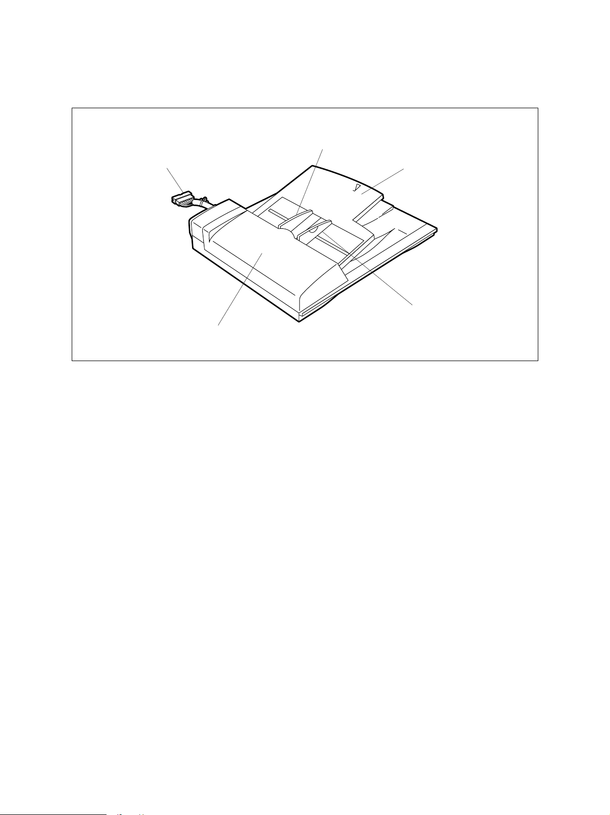
2.1 Names of Various Components
Document guide R
Connection Cable
Document tray
Document guide F
ADF top cover
ADF 02-01-01
October 2000 © TOSHIBA TEC 2 - 1 MR-2012 OUTLINE
Page 6
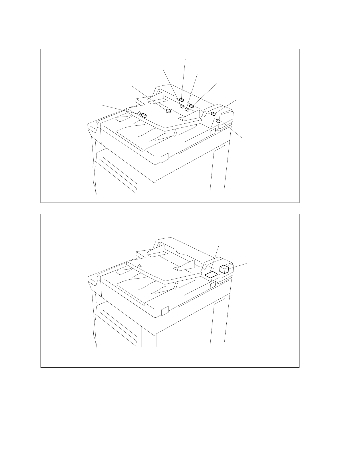
2.2 Layout of Electrical Parts
SEN4
SEN2
VR1
SEN3
SEN6
SEN5
SW1
SEN1
ADF 02-02-01
ADF PWA
M1
ADF 02-02-02
MR-2012 OUTLINE 2 - 2 October 2000 © TOSHIBA TEC
Page 7

Symbols and functions of various devices
Symbol
SW1
VR1
SEN1
SEN2
SEN3
SEN4
SEN5
SEN6
ADF
Name
ADFCOV-SW
ADF top cover open switch
WIDTH-VR
Document width sensor
ADFOPN-SEN
ADF open sensor
SIZE-SEN
Document length sensor
EMPTY-SEN
Document empty sensor
REGST-SEN
ADF registration sensor
POS-SEN
ADF read sensor
HAISI-SEN
ADF exit sensor
ADF PWA
Function
Detects the open/close state of the top cover
during jamming processing, etc.
Detects the width of document.
Detects the open/close state of the ADF unit.
Detects the length of document.
Detects the loading of document.
Detects the aligning position of document.
Detects the document scanning start position.
Detects the ejection of document.
PWA which relays the sensor signals and motor
M1
ADF-MOT
ADF motor
drive signals.
Drives the roller to transport originals.
October 2000 © TOSHIBA TEC 2 - 3 MR-2012 OUTLINE
Page 8
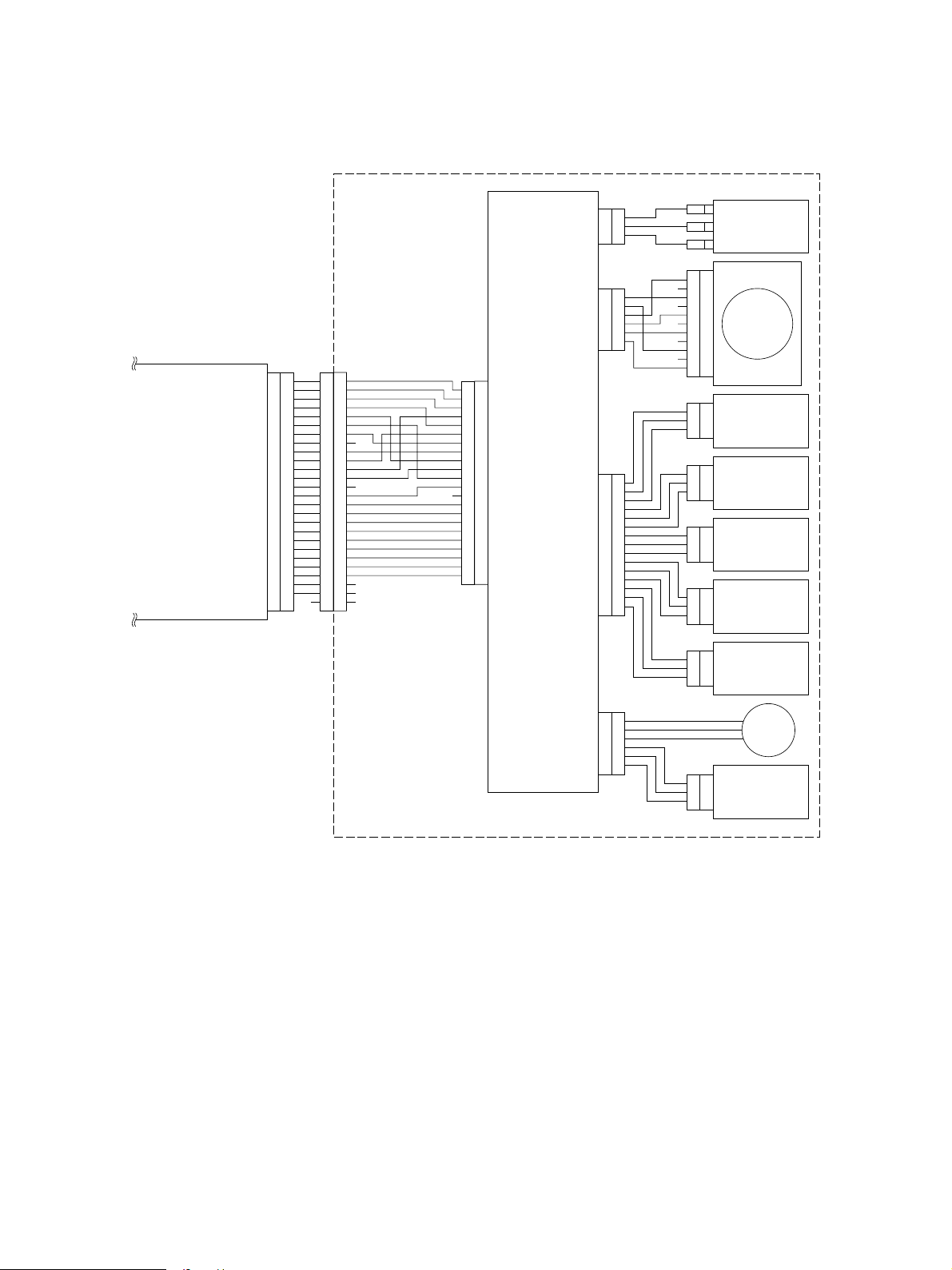
2.3 Harness Connection Diagram
ADF
CN2
MOT+24V
+24V
COVER
1
2
3
N.O.
COM
top cover open switch
N.C.
ADF
Scanner control PWA
CN6
+24V 1
+24V
2
/AA34
/BB56
PG 7
PG
8
+5V 9
D/A
10
POS 11
REGST/ACK
12
VALID/DFFAN 13
5VPS
14
EMPTY 15
DF OPN
16
COVER/RXD 17
SG
18
WIDTH/TXD 19
SG
20
HAISI/DF-ACK 21
SIZE2/DF-REQ
ADF CNT/REQ 23
22
RADF CNT
24
SG 25
NC FG FG
26
CN3
1
MOT+24V
2
MOT+24V
3
A
4
/A
5
B
6
/B
1
2
3
4
5
6
7
8
NC
9
10
11
12
13
NC
14
15
16
17
18
19
20
21
22
23
24
NC
25
NC
26
NC
CN1
1
2
3
4
5
6
7
8
9
10
11
12
ADF PWA
13
14
15
16
17
18
19
20
21
22
CN4
HAI+5V
HAISI
POS
REG+5V
REGST
EMP+5V
EMPTY
OPN+5V
DF_OPN
CN5
WIDTH+5V
WIDTH
SIZE+5V
SIZE
1
2
SG
3
4
+5V
5
6
D/A
7
8
SG
9
10
11
SG
12
13
14
SG
15
1
2
3
SG
4
5
SG
6
1
2
NC
3
NC
4
5
6
NC
NC
NC
CN12
CN6
CN9
CN10
CN11
CN12
ADF motor
7
8
9
10
11
3
2
ADF exit sensor
1
3
2
ADF read sensor
1
3
ADF registration
2
1
3
2
Document empty sensor
1
3
2
ADF open sensor
1
3
2
Document length sensor
1
sensor
Document
width
sensor
ADF 02-03-01
MR-2012 OUTLINE 2 - 4 October 2000 © TOSHIBA TEC
Page 9
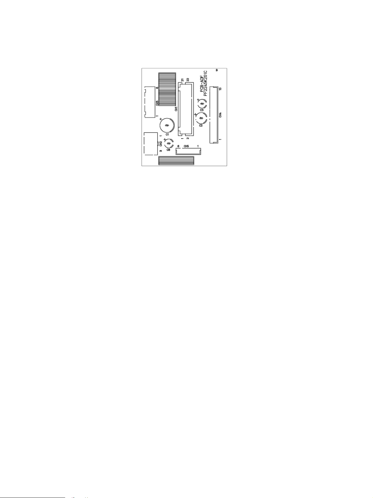
2.4 Board Assembly
ADF 02-04-01
October 2000 © TOSHIBA TEC 2 - 5 MR-2012 OUTLINE
Page 10

3. OPERATIONAL DESCRIPTION
3.1 General Operation
The ADF is an auto document feed unit capable of accommodating a maximum of 50 originals. The
originals loaded are fed and scanned one by one and stacked on the e xit tray. The ADF has a mechanical
section for document transport, sensors to detect the position of document, etc., and a motor for transport. It also has one PWA where comparator IC’s only are installed and the other signals simply pass.
For this reason, all control and processing are performed by the scanner PWA.
3.2 Block Diagram
ADF
Scanner
PWA
CN6
CN1
ADF
PWA
CN4CN5
CN2CN3
ADF read sensor
ADF open cover sensor
ADF registration sensor
Document empty sensor
ADF exit sensor
Document length sensor
Document width sensor
ADF top cover open switch
ADF motorM
ADF 03-02-01
October 2000 © TOSHIBA TEC 3 - 1 MR-2012 OPERA TIONAL DESCRIPTION
Page 11

3.3 Detection of Abnormal Status
3.3.1 Cover open/Close detection
When the ADF top cover is opened, the contact of the ADF top cover open switch changes to cut the
supply of 24V to the motor and sends a cover open detection signal to the scanner PWA.
3.3.2 Feeder jam detection
The number of pulses (time) equivalent to the distance ( ) from the document set position to the ADF
registration sensor ON position plus 300 mm is regarded as timing for detecting a jam. When the time
from the moment of starting paper feed to the moment when the ADF registration sensor is turned ON
exceeds that value, a jam in the feeder will be detected.
3.3.3 ADF registration sensor stay jam detection
The number of pulses (time) equivalent to the distance obtained by subtracting 115 mm ( + ) from
the document length plus 30 mm (1115 mm for long mode) is regarded as timing for detecting a jam.
When the time from the moment when the ADF exit sensor is turned ON to the moment when the ADF
registration sensor is turned OFF exceeds that value, a ADF registration sensor stay jam will be detected.
3.3.4 ADF read sensor unreached jam detection
The number of pulses (time) equivalent to the distance ( ) from the ADF registration sensor to the ADF
read sensor plus 30 mm is regarded as timing for detecting a jam. When the time from the moment of
starting the transport of the document having reached the ADF registration sensor to the moment when
the ADF read sensor is turned ON exceeds that value, an ADF read sensor unreached jam will be
detected.
3.3.5 ADF read sensor stay jam detection
The number of pulses (time) equivalent to the distance ( ) from the ADF registration sensor to the ADF
read sensor plus 30 mm is regarded as timing for detecting a jam. When the time taken after the end of
the document passes the ADF registration sensor exceeds that v alue , an ADF read sensor stay jam will
be detected.
3.3.6 ADF exit sensor unreached jam detection
The number of pulses (time) equivalent to the distance ( ) from the moment when the ADF read sensor
is turned ON to the moment when the exit sensor is turned ON plus 35 mm is regarded as timing for
detecting a jam. When the time tak en after the top of the document passes the ADF read sensor exceeds
that value, an ADF exit sensor unreached jam will be detected.
ADF registration sensor
ADF read sensor
Document empty sensor
ADF exit sensor
adf 03-03-06
MR-2012 OPERATIONAL DESCRIPTION 3 - 2 October 2000 © T OSHIBA TEC
Page 12

3.4 Flow Chart
Start button ON
Document feed from ADF
Scanning of document
Cassette feed
Copy
Ejection
NO
Scanning of
final document
YES
End
October 2000 © TOSHIBA TEC 3 - 3 MR-2012 OPERA TIONAL DESCRIPTION
Page 13

4. MECHANICAL DESCRIPTION
4.1 Paper Feed System
Document length sensor
ADF 04-01-01
ADF registration sensor
Registration roller
Read roller
Document empty sensor
Feed roller
ADF read sensor
Pickup roller
Flow of document
Exit roller
ADF exit sensor
Document width sensor
Transport of Document
When a document is placed in the tray, the document empty sensor detects the presence of a document.
When the Start button is pressed on the copier while in ADF mode, the ADF motor operates to lower the
pickup roller and pull in the document. Where there are more than one document, they are separated by
the separation pad under the feed roller and transported one by one.
The document transported by the feed roller is detected by the ADF registration sensor and then stopped
when the leading edge of the document reaches the registration roller after being fed f or a certain distance.
This feed amount can be adjusted by the aligning amount adjustment (05-354).
Then, the read roller rotates and the scanner starts scanning when the document reaches the ADF read
sensor.
The scanned document passes over the ADF exit sensor, then is ejected by the exit roller.
October 2000 © TOSHIBA TEC 4 - 1 MR-2012 MECHANICAL DESCRIPTION
01/05
Page 14

4.2 Document Size Detection Method
The size of document is found by detecting the document width by the document width sensor, and the
document length by the document length sensor. When documents of different sizes are placed in the
tray, this detection method allows the maximum size of the documents to be detected. The document
size is detected according to the timing with which the document empty sensor is turned ON, the timing
with which the document width sensor changes, and the timing with which the document length sensor
changes. The detected size is sent to the copier.
When the ADF is on standby or the document empty sensor is ON, the document width sensor is
checked e very 100 ms and the value obtained is compared with that of the last time. If the value is found
changed as a result of the comparison, the document size will be detected and sent to the copier when
in ADF active mode. When this unit receives a command accompanied by a document size notice
request from the copier, it will also detect and send the document size to the copier.
Document empty
sensor
Document width
sensor
Document length
sensor
ADF as viewed from top
The detection results of the document size sensors are listed below . (Unit: mm)
A4 series
Document width Document length sensor (*1)
OFF ON
129.40 - 165.99 A5R (148 x 210)
166.00 - 196.99 B5R (182 x 257)
197.00 - 233.99 A4R (210 x 297) FOLIO (210 x 330)
234.00 - 277.99 B5 (257 x 182) B4 (257 x 364)
278.00 - 310.00 A4 (297 x 210) A4 (297 x 420)
(*1: ON for a document length of 306 mm)
adf 04-02-01
MR-2012 MECHANICAL DESCRIPTION 4 - 2 October 2000 © TOSHIBA TEC
Page 15

L T series
Document width Document length sensor (*1)
OFF ON
129.40 - 177.99 STR (139.7 x 215.9)
178.00 - 236.99 LTR (215.9 x 279.4) LG (215.9 x 355.6)
237.00 - 268.99 COMPUTER (257.2 x 356)
269.00 - 310.00 LT (279.4 x 215.9) LD (279.4 x 431.8)
(*1: ON for a document length of 306 mm)
October 2000 © TOSHIBA TEC 4 - 3 MR-2012 MECHANICAL DESCRIPTION
Page 16

4.3 Drive System
Pickup roller
Front side
Spring Clutch
Rear side
ADF motor
One-way clutch
Feed roller
Read roller
ADF 04-03-01
The driving force of the ADF motor is transmitted to each roller through the gears and belts. It is transmitted to the feed rollers through the timing belt and gears (3 pcs.) and further transmitted to the pickup roller
through the timing belt. The driving f orce is transmitted to the read roller through the two timing belts and
the gears connecting them. The shaft part of the read roller is provided with a one-way clutch allo wing the
driving force of the ADF motor to be transmitted only in the transport direction (counterclockwise) for
rotation.
Document Feed
The document is fed as the ADF motor turns clockwise as viewed from the front (in the direction of the
black arrow). When the ADF motor turns clockwise, the pickup roller lowers to pull in the document. At
this time, the read roller does not turn due to the function of the one-way clutch.
Document Transport
The document is transported as the ADF motor turns counterclockwise as viewed from the front (in the
direction of the white arrow). When the ADF motor turns counterclockwise, the pickup roller ascends
causing the spring clutch mounted on the feed roller shaft to slip so that the driving force is no longer
transmitted.
MR-2012 MECHANICAL DESCRIPTION 4 - 4 October 2000 © TOSHIBA TEC
Page 17

5. CIRCUIT DESCRIPTION
5.1 PWA Block Diagram
ADF PWA
+24V
1
2
3
A
4
POS
5
/A
6
D/A
7
+5V
PG
8
B
9
REGST
10
/B
Relay PWA
11
CN1
P+5V
12
13
NC
EMPTY
14
DF-OPN
15
COVER
16
17
WIDTH
18
19
HAISI
20
21
SIZE
22
SG
1
MOT+24V
+24V
2
CN2
COVER
Q1
SG
IC1
-
1
+
-
2
+
-
13
+
-
14
+
+5V
6
7
4
5
10
11
+5V
R2
R4
SG
8
9
3
1
2
3
4
CN3CN4CN5
5
6
1
2
3
HAISI
4
5
6
7
REG+5V
8
9
P+5V
10
11
12
13
OPN+5V
14
15
SG
+5V
1
2
3
4
5
6
SIZE
SG
ADF
top cover open switch
ADF motor
ADF exit sensor
ADF read sensor
ADF registration sensor
Document empty sensor
ADF open sensor
Document
width
sensor
Document length sensor
ADF 05-01-01
5.2 Detection Circuit
The ADF top cover open s witch detects the open or close state of the ADF top cov er. 24V is supplied to
the motor when the cover is closed, and switches to the tr ansistor Q1 side when open. The output of Q1
turns to “Low” level when the cover is open and the detection signal is sent to the scanner PWA from
CN1.
The document width sensor uses a variable resistor for its detection element. It divides the v oltage of 5V
through the variable resistor and sends the output to the scanner PW A. The scanner PW A A-D conv erts
the input voltage to calculate the document width.
The outputs of the ADF exit sensor, ADF registration sensor, ADF open sensor, and document length
sensor each are input to the IC1 comparator. The reference voltage obtained by dividing 5V though R2
and R4 is input to the other input of the comparator. The detection level of each sensor is stabilized
according to this reference voltage value and output from the comparator. Since the document empty
sensor does not require accuracy for detecting the presence of a document, its output signal simply
passes through the ADF PWA.
October 2000 © TOSHIBA TEC 5 - 1 MR-2012 CIRCUIT DESCRIPTION
Page 18

5.3 ADF Read Sensor Input Circuit
ADFScanner
+5V
5
POS_DA
REF_DA
IPOS
POS_AD
The ADF read sensor input circuit is installed on the scanner PWA. The ADF PWA only allo ws the signal
+
IC7
6
-
3
+
IC7
2
-
R23
7
IC8
R18
7
1
5
+
6
-
R22
C19
Q2
R19
R17
C16C17
ADF 05-03-01
only to pass through. Therefore, this section describes the ADF read sensor input circuit on the scanner
PWA.
The ADF read sensor is a mirror reflective type sensor and consists of a pair of a infrared LED and a PTr
(phototransistor) each having an optical axis in the same direction. A mirror is provided on an extended
line of the optical axis of the sensor. When there is no document between the sensor and the mirror, an
infrared light emitted from the LED is reflected to PTr at high reflectance. When there is a document
between them, the emission to the mirror and the reflected light from the mirror are obstructed by the
document so that the reflected light incident on PTr becomes extremely low. When a quantity of light
incident on PTr is large (no document present), photoelectric current flowing through PTr increases and
a drop in voltage due to R17 causes the voltage at pin 6 of IC8 to rise.
IC8 is a comparator which compares the reference voltage input to pin 5 (non-inverting input) with the
signal voltage at pin 6 (inv erting input). When the voltage at pin 6 is higher , the output (pin 7 of IC8) turns
to “Low” level. Conversely, when a quantity of light incident on PTr is small (a document present), the
voltage at pin 6 of IC8 becomes low and as a result pin 7 of IC8 turns to “High” level.
An automatic sensitivity adjusting function is also provided to control variations in sensor sensitivity.
When the sensor sensitivity adjust mode is selected, the automatic adjustment measures the output
voltage (analog value) of PTr at the A-D input terminal on the scanner side, changes the D-A output
voltage on the scanner side to make the PTr output voltage become the required v oltage, and adjusts the
LED current through the voltage-current conversion circuit consisting of IC7, Q2, R20, etc.
MR-2012 CIRCUIT DESCRIPTION 5 - 2 October 2000 © TOSHIBA TEC
Page 19

5.4 ADF Motor Drive Circuit
Scanner control PWA
IC1
Scanner MPU
+24V
1,2
CPUA0~19
CPUD0~15
5,16
2,13
6
17
3
14
IC10
Motor driver
+5V
2
1
Q1
5
R5C6C7
SG PGSGSG
A
13
/A
84
B
11 5
/B
18
9
10
R1,R2
R3,R4
IC4
Motor
control IC
76
74
77
78
72
75
APWM
ACKO
ASTB
ADTA
ADTB
AENB
R8 R7 R6
The ADF motor operates according to the driving signals from the scanner PWA. The signals only pass
ADF top cover open switch
1,2
3
CN6
CN1
5
9
6
11
CN2
21
ADF PWA
1,2
ADF motor
3
CN3
4
5
6
A
/A
B
/B
ADF 05-04-01
through the ADF PWA. Therefore, this section describes the ADF motor drive circuit on the scanner
PWA.
The ADF motor is driven by amplifying the pulse motor driving pattern signals output from the gate array
through the IC10 motor driver. These signals control the motor rotational direction and speed. The PWM
signal is input to APWM and converted to a certain voltage through the resistor and capacitor. The
voltage is input to IC10 (pins 3 and 14) to set the current value for the motor.
The current value for the motor can be set as desired b y changing the duty of the PWM signal. AENB is
a signal to control the output of the motor driver. When the signal is at “High” level, the output of the driver
becomes effective.
October 2000 © TOSHIBA TEC 5 - 3 MR-2012 CIRCUIT DESCRIPTION
Page 20

5.5 Meaning of Signals
Signal name
COVER
DF_OPN
SIZE
WIDTH
EMPTY
REGST
POS
HAISI
Part name
ADF top cover
open switch
ADF open
sensor
Document
length sensor
Document width
sensor
Document
empty sensor
ADF registration
sensor
ADF read
sensor
ADF exit sensor
Functional description
Detects the open/close state
of the top cover during jamming processing, etc.
Detects the open/close state
of the ADF unit.
Detects the length of document.
Detects the width of document.
Detects the loading of document.
Detects the aligning position
of document.
Detects the document scanning start position.
Detects the ejection of document.
Status
-
Low: Open
Low: Document present
-
Low: Document present
Low: Document present
Low: Document present
Low: Document present
Note
Microswitch
Photo sensor
Photo sensor
Variable resistor
Photo sensor
Photo sensor
Photo sensor
Photo sensor
The ADF top cover open s witch detects the open or close state of the cover and uses a 2-circuit microswitch.
24V is supplied to the motor when the cover is closed, and cut when open.
The ADF open sensor detects the open/close state of the ADF unit. A photo sensor is used for the
sensor.
The document length sensor detects the length of the document placed in the document tray. A photo
sensor is used for the sensor. It turns ON when the document length exceeds 306 mm.
The document width sensor detects the width of the document. A v ariable resistor is used f or the sensor.
The resistive value changes as the document width guide is slid.
The ADF empty sensor detects the document placed in the document tray. A photo sensor is used for
the sensor.
The ADF registration sensor detects the document position in the transport path. A photo sensor is used
for the sensor. It detects a paper jam in combination with other sensors.
The ADF read sensor detects the document scanning start position. A mirror reflective type photo
sensor is used for the sensor. It detects the presence or absence of a document according to the
strength of reflected light from the mirror.
The document exit sensor detects the ejection of a document. A photo sensor is used for the sensor.
MR-2012 CIRCUIT DESCRIPTION 5 - 4 October 2000 © TOSHIBA TEC
Page 21

5.6 Timing Chart
(14)
(11)
Pre-feed Paper-feed Scan Eject
(12) (13)
(11)
(3) (4) (5) (1) (3) (4) (5) (6)
(10) (10)
(9) (9)
(2) (2)
ON
(8) (8)
OFF
ON
OFF
ON
OFF
ON
(1)
Forward
OFF
OFF
Reverse
ADF motor
October 2000 © TOSHIBA TEC 5 - 5 MR-2012 CIRCUIT DESCRIPTION
Document
empty sensor
ADF registration
sensor
ADF read sensor
ADF exit sensor
ADF 05-06-01
Page 22

6. DISASSEMBLY AND REPLACEMENT
[A] ADF unit
1. Release 2 hooks, and detach ADF cover.
2. Release the clamp and detach one connector.
3. Open ADF unit and take it out by lifting.
Hook
ADF cover
ADF unit
Connector
Fig. 6-1
Fig. 6-2
Clamp
160
161
[B] Document tray assembly
1. Open ADF top cover.
2. Remove one screw, release 3 hooks, and detach ADF cover R.
3. Detach one connector from ADF PWA (CN5).
ADF top cover
162
Fig. 6-3
ADF cover R
Screw
Hook
ADF PWA
Hook
CN5
Connector
163
Fig. 6-4
October 2000 © TOSHIBA TEC 6 - 1 MR-2012 DISASSEMBLY AND REPLACEMENT
Page 23

4. Remove one scre w and remove document tr ay
support.
5. Detach document tray support from the harness.
6. Move document tray assembly in the direction
of the arrow and remove it.
Document tray
assembly
Document
tray support
[C] Document tray cover
1. Remove ADF. (See Fig. 6-1 and 6-2)
2. Remove document tra y assembly. (See Fig. 6-3
to 6-5)
3. Remove 3 screws and detach document tray
cover.
[D] Document width sensor assembly
1. Remove ADF. (See Fig. 6-1 and 6-2)
2. Remove document tra y assemb ly.
(See Fig. 6-3 to 6-5)
3. Detach document tray co v er . (See Fig. 6-6)
4. Release the harness from the clamp and detach the document length sensor harness.
Document width
volume assembly
Harness
Fig. 6-5
Screw
Fig. 6-6
Screw
Document
tray cover
Screw
164
165
5. Remove one screw, release the hook, and re-
Clamp
move document width sensor assembly.
Clamp
166
Fig. 6-7
Notes: 1. Align the arrow ( ↑ ) mark of sensor
holder with that of document guide
Sensor holder
Document guide
rack
gear.
2. Align the cut part of document guide rack
with the triangle mark ( ) of document
guide gear.
Document
guide gear
Document guide
rack
MR-2012 DISASSEMBLY AND REPLACEMENT 6 - 2 October 2000 © TOSHIBA TEC
Fig. 6-8
167
Page 24

[E] ADF top cover assembly
1. Remove document tra y assembly . (See Fig. 6-3
to 6-5)
2. Detach 2 stop rings, release the tab, and remove ADF top cov er assemb ly.
Stop ring
ADF top cover
assembly
Stop ring
[F] ADF pickup roller assembly/ADF pic kup roller/
ADF pickup feed roller
1. Open ADF top cover . (See Fig. 6-3)
2. Remove 2 screws , and remove ADF document
guide.
3. Remove two each of stop ring and bushing and
remove ADF pickup roller assemb ly.
ADF document guide
Fig. 6-9
Fig. 6-10
Stop ring
Bushing
168
Screw
169
Stop ring
170
4. Detach 2 stop rings and remove shutter stop-
ADF pickup roller
assembly
ADF holder F
Fig. 6-11
Stop ring
per.
5. Slide ADF holder F in the direction of the arrow
Straight Pin
Shutter Stopper
and draw out pin.
Shutter Stopper
171
Fig. 6-12
October 2000 © TOSHIBA TEC 6 - 3 MR-2012 DISASSEMBLY AND REPLACEMENT
Page 25

6. Remove Spring, ADF holder F, and washers in
this order, and remov e timing belt.
7. Remove ADF pickup roller and ADF pickup f eed
roller.
Note: Apply 0.1g of Sumitec 505 No . 1 (white) to
the outer circumference of the spring.
ADF pickup
feed roller
Spring
Washer
ADF pickup roller
Timing belt
[G] ADF pad/brake pad
1. Open ADF top cover. (See Fig. 6-3)
2. Release the hook and remove ADF pad unit.
3. Release the tab and remove ADF pad.
Hook
ADF holder F
Fig. 6-13
Hook
Fig. 6-14
Tab
172
ADU pad unit
Hook
173
ADF pad
174
Fig. 6-15
4. Remove the old brak e pad, wipe off the mount-
Brake pad
ing surface, and mount a new br ake pad to the
position shown below .
Brake pad
175
Fig. 6-16
MR-2012 DISASSEMBLY AND REPLACEMENT 6 - 4 October 2000 © TOSHIBA TEC
Page 26

[H] ADF PWA
1. Open ADF top cover . (See Fig. 6-3)
2. Remove one screw, release 3 hooks, and detach ADF cover R.
Screw
ADF cover R
Hook
Hook
3. Detach all the connectors from ADF PWA.
4. Remove 2 screws and remov e ADF PWA.
[I] ADF feed guide assembly
1. Remove document tra y assemb ly.
(See Fig. 6-3 to 6-5)
2. Remove ADF top cov er assemb ly.
(See Fig. 6-9)
3. Detach the connectors from ADF PWA (CN2CN4), remove one screw , and detach the ground
Fig. 6-17
176
Screw
ADF PWA
177-1
Fig. 6-18
Connector
ADF PWA
CN2 CN3
CN4
wire.
Ground wire
Fig. 6-19
4. Remove 4 screws, release 2 hooks , and remove
ADF feed guide assembly.
Hook
ADF feed guide assembly
Screw
Hook
Fig.6-20
October 2000 © TOSHIBA TEC 6 - 5 MR-2012 DISASSEMBLY AND REPLACEMENT
Screw
177-2
Screw
Hook
178
Page 27

Note: Mount ADF feed guide assemb ly with mylar
on exit pinch roller up.
[J] ADF feed motor assembly
1. Remove document tra y assemb ly.
(See Fig. 6-3 to 6-5)
2. Remove ADF top cov er assemb ly.
(See Fig. 6-9)
3. Remove ADF f eed guide assembly.
(See Fig. 6-19 and 6-20)
4. Detach one connector from platen sensor, and
release the harness of ADF feed motor assembly from the clamp.
5. Remove one screw and detach the ground wire .
Mylar
Exit pinch roller
Harness
Clamp
Fig. 6-21
Ground wire
Platen sensor
Fig. 6-22
ADF feed guide
assembly
179
Screw
Connector
180
6. Remove 3 scre ws, release timing belt 166, and
remove ADF f eed motor assembly.
7. Remove tension spring 2.
Tension spring
Screw
Fig. 6-23
Screw
ADF feed
motor assembly
Timing belt 166
181
MR-2012 DISASSEMBLY AND REPLACEMENT 6 - 6 October 2000 © TOSHIBA TEC
Page 28

Notes: Installation procedure for timing belt 166
1. While hooking timing belt 166 around
feed pulley M-66, secure ADF feed motor assembly with 2 screws.
2. Mount tension spring 2 and secure the
Screw
ADF feed motor
assembly
Timing belt 166
Tension spring 2
Fig. 6-24
Screw
Feed pully M-66
182
belt bracket 2 with one scre w.
[K] Read roller shaft assembly/ Read r oller shaft
1. Remove document tra y assemb ly.
(See Fig. 6-3 to 6-5)
2. Remove ADF top cov er assemb ly.
(See Fig. 6-9)
3. Remove ADF feed guide assemb ly.
(See Fig. 6-19 and 6-20)
4. Remove ADF feed motor assemb ly.
(See Fig. 6-22 and 6-23)
5. Remove one screw, release 2 hooks, and de-
Belt bracket 2
Screw
Fig. 6-25
Screw
Fig. 6-26
183
Sensor cover R
Hook
184
tach sensor cover R.
October 2000 © TOSHIBA TEC 6 - 7 MR-2012 DISASSEMBLY AND REPLACEMENT
01/05
Page 29

6. Remove one scre w and remo v e e xit plate .
Screw
Exit plate
7. Release 4 hooks and detach harness cover .
8. Remove one screw and remo ve the ground wire
and ADF registration sensor brack et.
Hook
Harness cover
ADF registration
sensor bracket
Fig. 6-27
Fig. 6-28
Screw
185
Hook
186
Ground wire
187
Fig. 6-29
9. Remove one screw and remo ve the ground wire
and ADF exit/read sensor bracket while push-
Screw
Ground wire
ADF exit/read sensor bracket
ing the part indicated by the arrow.
Fig. 6-30
MR-2012 DISASSEMBLY AND REPLACEMENT 6 - 8 October 2000 © TOSHIBA TEC
188-1
Page 30

10. Remove the mylar sheet.
Mylar sheet
188-2
Fig. 6-31
Note: Before attaching the mylar sheet, wipe the
surface to be attached. Attach the mylar
sheet by holding it to the two ends. Attach
the sheet securely with no portion lifted.
11. Detach the E-ring and remove f eed pulley M-66.
Mylar sheet
188-3
Fig. 6-32
Feed pulley M-66
E-ring
Fig. 6-33
189
12. Detach the E-r ing, slide bearing inwards, and
remove Read roller shaft assembly.
Bearing
E-ring
Read roller shaft assembly
Bearing
190
Fig. 6-34
October 2000 © TOSHIBA TEC 6 - 9 MR-2012 DISASSEMBLY AND REPLACEMENT
01/05
Page 31

13. Detach the E-r ing from Read roller shaft and
remove bearing.
14. Detach ADF knob from Read roller shaft and
remove bearing and spring.
E-ring
Spring
Read roller shaft
E-ring
Bearing
Jam dial
[L] ADF front cover
1. Open ADF unit.
2. Release 3 screws and hook and detach ADF
front cover by sliding it in the direction of the
arrow.
Bearing
Fig. 6-35
Fig. 6-36
ADF front cover
Screw
191-1
191-2
MR-2012 DISASSEMBLY AND REPLACEMENT 6 - 10 October 2000 © TOSHIBA TEC
01/05
Page 32

1-1, KANDA NISHIKI-CHO , CHIYODA-KU, TOKYO , 101-8842 JAPAN
 Loading...