

Page 1

SERVICE MANUAL
LARGE CAPACITY FEEDER
MP-4003
File No.31100203
2002-06
Page 2

Copyright 2002
TOSHIBA TEC CORPORATION
Page 3

GENERAL PRECAUTIONS FOR INSTALLATION/SERVICE/ MAINTENANCE FOR LARGE CAPACITY FEEDER MP-4003
1. When installing the Large Capacity Feeder MP-4003 to the Copier, be sure to follow the instructions
described in the “Unpacking/Set-Up Procedure for the MP-4003” booklet which comes with each
unit of the MP-4003.
2. Installed only by an authorized/qualified person.
3. When transporting/installing the MP-4003, employ two persons. The MP-4003 is fairly heavy and
weights approximately 40 kg (89 lb), therefore pay full attention when handling it.
4. Before starting installation, servicing or maintenance work, be sure to turn off and unplug the
copier first.
5. Supplied with power from the copier, requiring no additional power source.
6. Grounded to the specified positions on the machine frame.
7. When serving or maintaining, be careful about the rotating or operating sections such as gears,
pulleys, sprockets, cams, belts, etc.
8. When parts are disassembled, reassembly is basically the reverse of disassembly unless otherwise
noted in this manual or other related documents. Be careful not to reassemble small parts such as
screws, washers, pins, E-rings, toothed washers to the wrong places.
9. Basically, the machine should not be operated with any parts removed or disassembled.
10. Delicate parts for preventing safety hazard problems (such as thermofuses, door switches sensors,
etc. if any) should be handled/installed/adjusted correctly.
11. During servicing or maintenance work, be sure to check the nameplate and other cautionary labels (if
any) to see if they are clean and firmly stuck. If not, take appropriate actions.
12. Use suitable measuring instruments and tools.
13. The PC board must be stored in an anti-electrostatic bag and handled carefully using a wristband,
because the ICs on it may be damaged due to static electricity.
Caution: Before using the wrist band, pull out the power cord plug of the copier and make sure that
there is no uninsulated objects in the vicinity.
14. For the recovery and disposal of used the large capacity feeder, consumable parts, packing materials,
used batteries, and RAM-ICs including litium batteries, it is recommended that the relevant local
regulations/rules.
Page 4

CONTENTS
1. SPECIFICATIONS .......................................................................................... 1-1
2. OUTLINE OF THE MACHINE......................................................................... 2-1
2.1 Front Sectional View ...................................................................................................... 2-1
2.2 Electrical Parts Layout................................................................................................... 2-2
2.3 Electrical Parts ..............................................................................................................2-4
3. GENERAL OPERATION ................................................................................. 3-1
3.1 Description of Operation ................................................................................................ 3-1
3.2 Error Detection............................................................................................................... 3-2
3.3 Flow Chart ..................................................................................................................... 3-3
3.4 Timing Chart .................................................................................................................. 3-5
4. DISASSEMBLY AND REPLACEMENT/ADJUSTMENT................................... 4-1
4.1 Covers ........................................................................................................................... 4-1
4.2 Tray Unit ......................................................................................................................... 4-2
4.3 Feeder Unit..................................................................................................................... 4-3
4.4 Electrical Parts .............................................................................................................. 4-4
4.5 Rollers ............................................................................................................................ 4-6
4.6 Side Guides / End Guide ................................................................................................ 4-7
4.7 Tray wire ......................................................................................................................... 4-8
4.8 Sidewise Deviation Adjustment .................................................................................... 4-11
4.9 Stopper Adjustment ..................................................................................................... 4-11
5. ELECTRICAL CIRCUIT .................................................................................. 5-1
5.1 Harness Diagram ........................................................................................................... 5-1
5.2 Circuit Diagram .............................................................................................................. 5-2
5.3 PC Board........................................................................................................................ 5-5
6. PERIODIC MAINTENANCE ........................................................................... 6-1
JUNE 2002 © TOSHIBA TEC I MP-4003 CONTENTS
Page 5

1. SPECIFICATIONS
Function
Replenishing method ......Front loading method
Paper .............................. Size: A4, B5, LT
Thickness: 64~209g/m2 (17~110lbs. Index)
Capacity of tray .............. 4,000 papers (Stack height: within 428mm)
Dimensions .....................326 (W) X 599 (D) X 617 (H) mm (when connected to the copier)
Weight ............................ Approx. 40kg (89lbs)
Power supply................... DC5V, 24V (supplied from the copier)
JUNE 2002 © TOSHIBA TEC 1 - 1 MP-4003 SPECIFICATIONS
Page 6
2. OUTLINE OF THE MACHINE
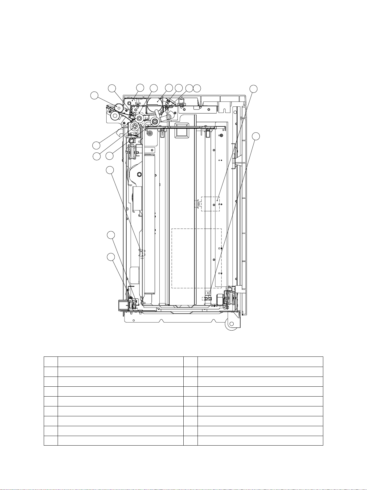
2. 1 Front Sectional View
16
14
15
13
12
9
11
7
3
1
4
8
6
5
2
10
NO. NAME NO. NAME
1 Transport motor (M1) 9 Tray sensor (S5)
2 Tray motor (M2) 10 Tray bottom sensor (S6)
3 Transport clutch (CL1) 11 LCF set sensor (S7)
4 Feed clutch (CL2) 12 Door switch (SW1)
5 Empty sensor (S1) 13 Pickup roller
6 Tray-up sensor (S2) 14 Feed roller
7 Feed sensor (S3) 15 Separation roller
8 FG-pulse sensor (S4) 16 Transport roller
JUNE 2002 © TOSHIBA TEC 2 - 1 MP-4003 OUTLINE OF THE MACHINE
Page 7
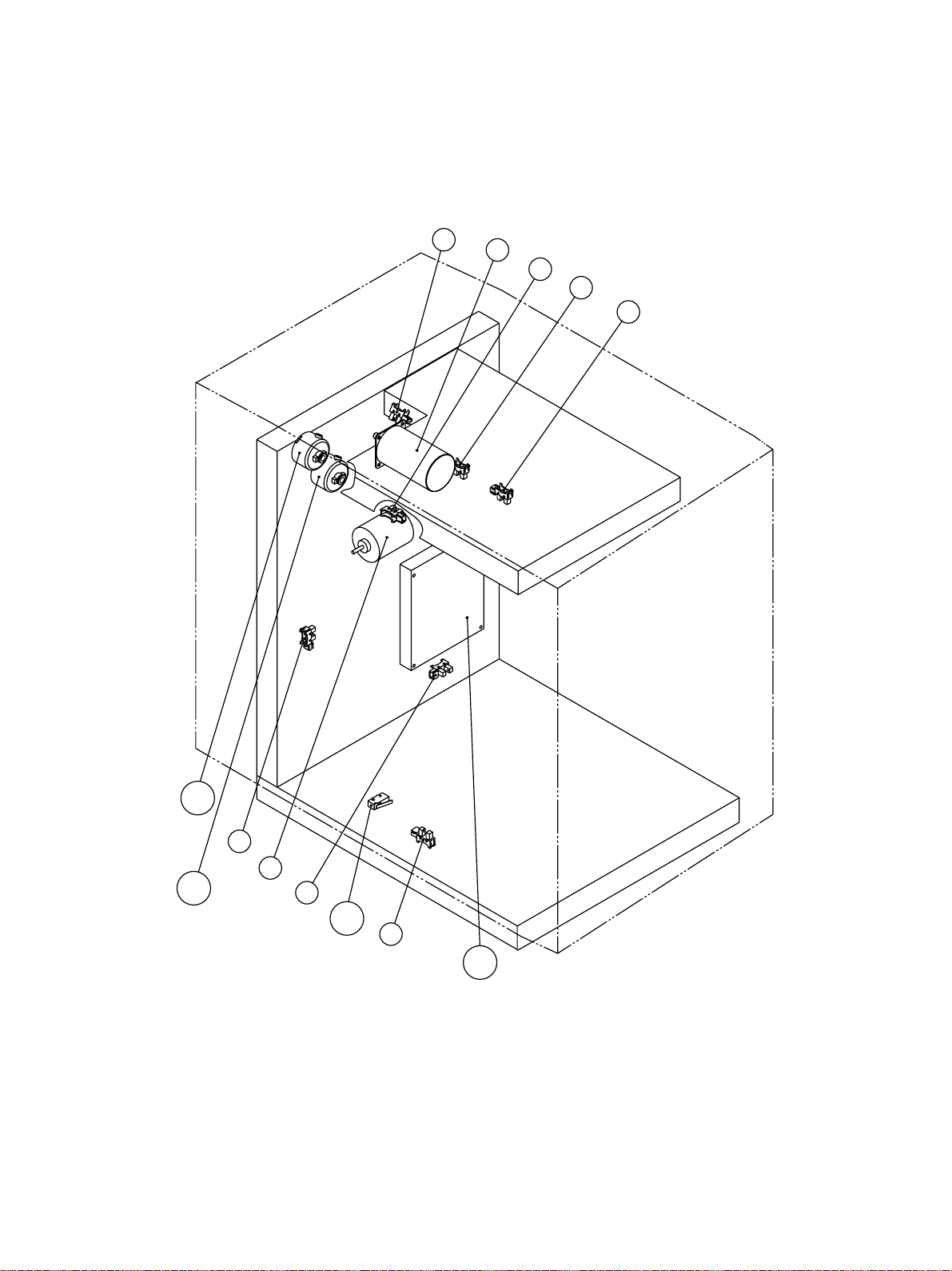
2. 2 Electrical Parts Layout
CL1
CL2
S5
M2
S6
SW1
S7
S4
M1
S3
S1
S2
S4
M1
S3
S1
S2
CL1
S5
M2
CL2
JUNE 2002 © TOSHIBA TEC 2 - 2 MP-4003 OUTLINE OF THE MACHINE
S6
SW1
S7
PWPWA
Page 8

2. 3 Electrical Parts
(1) Motors
SYMBOL NAME FUNCTION REMARKS
M1 TR-MTR Driving of the feeding and Brush motor
Transport motor transportation
M2 TRY-MTR Lifting/Lowering of the tray Brush motor
Tray motor
(2) Electromagnetic clutches
SYMBOL NAME FUNCTION REMARKS
CL1 TR-CLT Driving of the transportation
Transport clutch
CL2 FED-CLT Driving of the feeding
Feed clutch
(3) Switches/Sensors
SYMBOL NAME FUNCTION REMARKS
S1 EMP-SNR Detection of the presence or Photo interrupter
Empty sensor absence of paper
S2 TRY-UP-SNR
Tray-up sensor
S3 FED-SNR Detection of the paper Photo interrupter
Feed sensor transportation
S4 FG-PULS-SNR
FG-pulse sensor rotation number
S5 TRY-SNR Detection of the drawer Photo interrupter
Tray sensor installed
S6 TRY-BTM-SNR
Tray bottom sensor
S7 LCF-SET-SNR Detection of the LCF installed Photo interrupter
LCF-set sensor to the copier
SW1 DOOR-SW Safety switch Pushing switch
Door switch
Detection of the tray upper limit
position
Detection of the transport motor
Detection of the tray lower limit
position
Photo interrupter
Photo interrupter
Photo interrupter
(4) PC Board
SYMBOL NAME FUNCTION REMARKS
PWA PWA-F-LCF-555 Driving of the feeding
PC board Control of the tray driving
JUNE 2002 © TOSHIBA TEC 2 - 3 MP-4003 OUTLINE OF THE MACHINE
Page 9

3. GENERAL OPERATION
3. 1 Description of Operation
[A] From power ON to standby
(1) When the copier is turned ON, power is also supplied to the feed unit from the copier to start the pre-
running operation. The tray motor (M2) starts to rotate forward to lift the tray.
The tray motor (M2) stopped rotating and lifting the tray when the tray has been lifted and the tray-up
sensor (S2) has been turned ON (H: Sensor light path blocked by the actuator sensor). Papers are
assessed to be present when the empty sensor (S1) is turned ON (L:Passing the sensor light path )
while they are assessed to be absent when the empty sensor (S1) is turned OFF (H: Sensor light path
blocked).
(2) When the LCF is not being installed to the copier (LCF set sensor (S7): OFF) or when the drawer is
being pulled out (Tray sensor (S5): OFF), the tray lifting operation is not carried out. In this case, the
tray starts to be lifted and the same operation which is until the detection of the paper presense or
absense is carried out when it is installed to the copier and the drawer is inserted.
(3) When the feed sensor (S3) is turned ON (L: Passing the sensor light path), that is, when the paper is
remaining at the transport path, the LCF detects it as a paper jam and cannot operate.
[B] Standby state
(1) When a paper is detected to be present by the above-described operation, the LCF gets into a standby
state.
(2) When the tray unit is pulled out, the tray is automatically lowered because of its structure, and when it
is inserted once again, it is lifted.
[C] Feeding/Transporting operation from the start to the finish of the printing
(1) The [START] key is pressed when the copier decides that the feeding from the the LCF. Then, the
transport motor (M1) starts to drive after the feed motor of the copier has been turned ON.
(2) The feed clutch (CL2) is turned ON and pickup and feed rollers start to drive to feed a paper from the
tray.
(3) After the feeding starts, the transport clutch (CL1) is turned ON and the transport roller starts to drive
to transport the paper.
(4) When the leading edge of the paper has turned ON the feed sensor (S3), the feed clutch (CL2) is turned
OFF and stops the feeding operation. The paper transported by the transport roller is sent to the copier
side, where it is transported by the feed unit.
(5) When a specified time has passed after the trailing edge of the paper turned OFF the feed sensor (S3),
next paper can be fed.
(6) When carrying out a continuous printing, the above steps from (2) to (5) are repeated as many papers
as printed.
(7) When the printing has been finished, the feed motor of the copier stops rotating and the transport motor
(M1) is turned OFF to finish the feeding/transporting operation.
JUNE 2002 © TOSHIBA TEC 3 - 1 MP-4003 GENERAL OPERATION
Page 10

[D] Tray operation during printing
(1) When 10~20 sheet of paper have been fed from the tray, the pickup roller is lowered down to a
specified height. The tay-up sensor (S2) detects this and the tray motor (M2) rotates forward to lift
the tray.
3. 2 Error Detection
[A] Jam detection
In the following cases, the feed jam takes place.
(1) When the feed sensor (S3) is not turned ON in a specified time after the feeding has started.
(2) When each transport sensor of the copier does not operate (ON/OFF) in a specified time after the
feeding has started at the copier side.
[B] Call for service
(1) When the tray-up sensor (S2) is not turned ON in a specified time after the tray has started to be lifted.
JUNE 2002 © TOSHIBA TEC 3 - 2 MP-4003 GENERAL OPERATION
Page 11
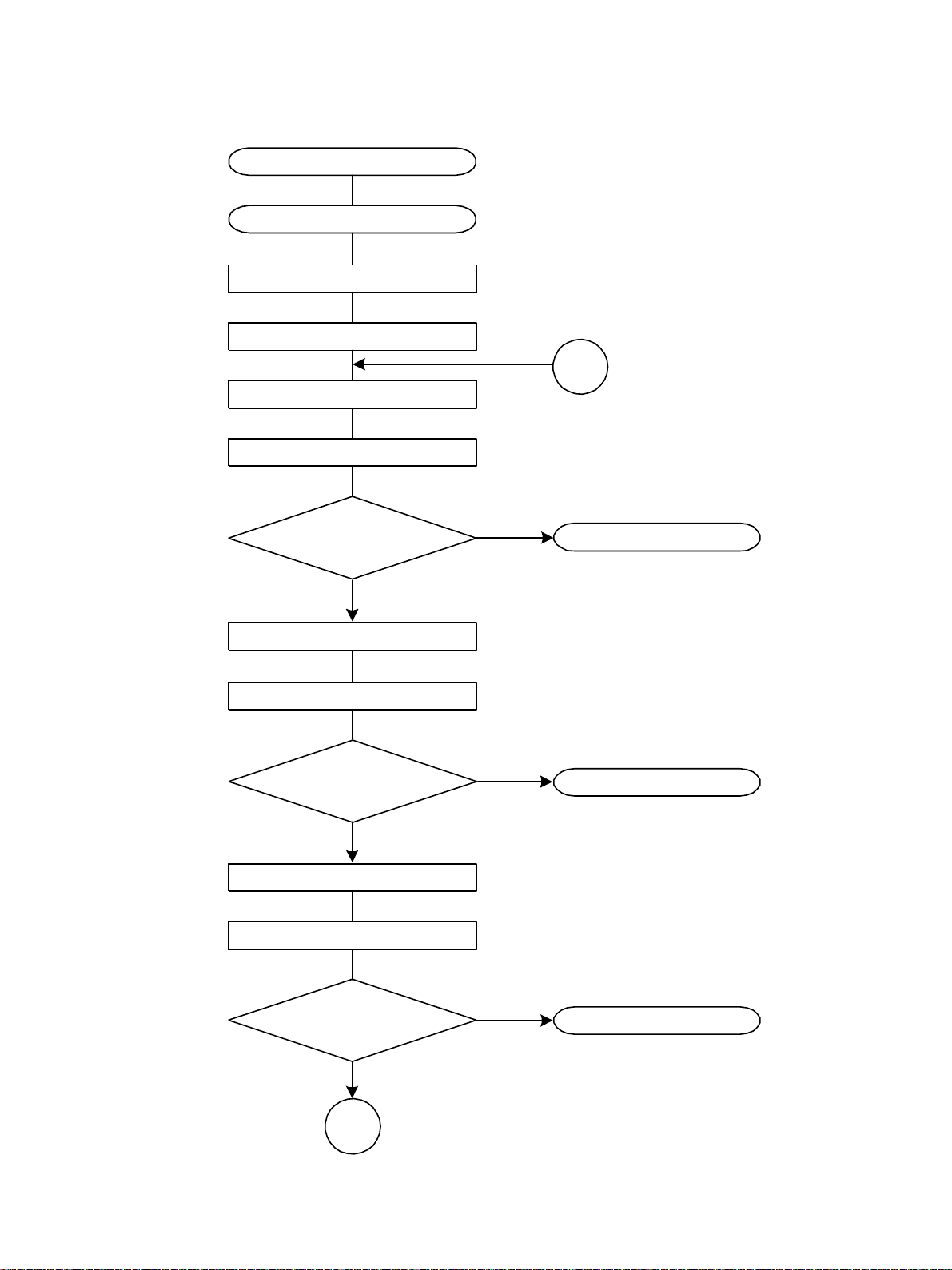
3. 3 Flow Chart
Press the [START] key
Transport system controlling
Copier feed motor ON
LCF transport motor ON
LCF feed clutch ON
LCF transport clutch ON
Is the LCF feed sensor ON?
YES
B
NO
Paper jam
(E19)
Copier intermediate transport clutch ON
LCF feed sensor ON
Is the copier intermediate
transport sensor ON?
YES
LCF feed sensor OFF
LCF transport clutch OFF
Is the copier registration
sensor ON?
YES
NO
Paper jam
(E25)
NO
Paper jam
(E25)
A
JUNE 2002 © TOSHIBA TEC 3 - 3 MP-4003 GENERAL OPERATION
Page 12

A
Copier intermediate transport clutch ON
Copier registration motor ON
Copier registration motor OFF
Is there no remaining copy?
YES
Is the copier fuser unit
exit sensor ON?
YES
Is the copier fuser unit
exit sensor OFF?
YES
LCF transport motor OFF
Copier feed motor OFF
NO
NO
NO
B
Paper jam
(E01)
Paper jam
(E02)
Standby
JUNE 2002 © TOSHIBA TEC 3 - 4 MP-4003 GENERAL OPERATION
Page 13

3. 4 Timing Chart
(1) Timing at the LCF feeding: A4, 1 copy
3700
(unit: ms)
1650
1410
OFF
800
ON
OFF
800
690
570
385
180
75
0
ON
OFF
ON
OFF
ON
OFF
180
ON
OFF
ON
Transport motor
JUNE 2002 © TOSHIBA TEC 3 - 5 MP-4003 GENERAL OPERATION
Feed clutch
Transport clutch
Feed sensor
Copier intermediate
transport sensor
Copier registration sensor
Page 14

(2) Timing at the LCF feeding: A4, 2 copies
4450
(unit: ms)
2410
1740
1660
1345
900 1185
745
400
200
70
0
865
710
200
1435 1520 2170
585
1760
825 1675
ON
OFF
ON
OFF
ON
OFF
ON
OFF
ON
ON
OFF
Transport motor
JUNE 2002 © TOSHIBA TEC 3 - 6 MP-4003 GENERAL OPERATION
Feed clutch
Transport clutch
Feed sensor
Copier intermediate
transport sensor
OFF
Copier registration
sensor
Page 15

(3) Timing at the LCF feeding: B5, 1 copy
3640
(unit: ms)
1605
1370
820
740
630
400
OFF
190
ON
190
75
0
ON
OFF
ON
OFF
ON
OFF
570
ON
OFF
ON
OFF
Transport motor
JUNE 2002 © TOSHIBA TEC 3 - 7 MP-4003 GENERAL OPERATION
Feed clutch
Transport clutch
Feed sensor
Copier intermediate
transport sensor
Copier registration sensor
Page 16

(4) Timing at the LCF feeding: B5, 2 copies
4390
(unit: ms)
1665
1560
2340
2100
1760
1515
OFF
1370
585
ON
OFF
825 1610
ON
OFF
1325
790
680 830 1160
400
200
OFF
80
ON
OFF
ON
0
ON
OFF
640
200
ON
Transport motor
JUNE 2002 © TOSHIBA TEC 3 - 8 MP-4003 GENERAL OPERATION
Feed clutch
Transport clutch
Feed sensor
Copier intermediate
transport sensor
Copier registration
sensor
Page 17

(5) Timing at the LCF feeding: LT, 1 copy
3750
(unit: ms)
1700
1460
835
725
590
415
OFF
210
ON
OFF
ON
210
OFF
70
ON
OFF
ON
0
ON
OFF
830
ON
OFF
Transport motor
JUNE 2002 © TOSHIBA TEC 3 - 9 MP-4003 GENERAL OPERATION
Feed clutch
Transport clutch
Feed sensor
Copier intermediate
transport sensor
Copier registration sensor
Page 18

(6) Timing at the LCF feeding: LT, 2 copies
4450
(unit: ms)
2420
1750
1650
1450 1520 2185
1330
910 1170
755
400
195
80
0
870
715
585
195
1765
825 1690
ON
OFF
ON
OFF
ON
OFF
ON
OFF
ON
ON
OFF
Transport motor
JUNE 2002 © TOSHIBA TEC 3 - 10 MP-4003 GENERAL OPERATION
Feed clutch
Transport clutch
Feed sensor
Copier intermediate
transport sensor
OFF
Copier registration
sensor
Page 19

4.
DISASSEMBLY AND REPLACEMENT
/ADJUSTMENT
4. 1 Covers
[A] Front cover
(1) Pull out the drawer.
(2) Remove 4 screws and take off the front cover.
Front cover
Note: When installing the front cover, fit the arm on the
latch lever.
[B] Rear cover
(1) Remove 4 screws and take off the rear cover.
Arm
Rear cover
[C] Upper cover
(1) Pull out the drawer.
(2) Remove the rear cover.
(3) Loosen 4 screws and take off the upper cover.
Upper cover
JUNE 2002 © TOSHIBA TEC 4 - 1 MP-4003 DISASSEMBLY AND REPLACEMENT
Page 20

[D] Right cover
(1) Remove 2 screws and take off the right cover
sliding it toward the front side.
4. 2 Tray Unit
(1) Pull out the drawer.
(2) Remove 1 screw and take off the stopper.
Right cover
(3) Remove 4 screws (2 for the left side and 2 for
the right side) and take off the tray unit pulling it
upward.
Stopper
Left side
Right side
JUNE 2002 © TOSHIBA TEC 4 - 2 MP-4003 DISASSEMBLY AND REPLACEMENT
Page 21

4. 3 Feed Unit
(1) Remove the upper cover.
(2) Remove the lever.
(3) Disconnect 2 connectors (for tray motor, PC
boad).
Lever
(4) Remove 3 screws for each at the front and
rear sides and take off the feed unit upward.
Connector
Feed unit
Front side
Rear side
JUNE 2002 © TOSHIBA TEC 4 - 3 MP-4003 DISASSEMBLY AND REPLACEMENT
Page 22

4. 4 Electric Parts
[A] PC board
(1) Remove the rear cover.
(2) Disconnect 4 connectors and remove 1 screw
to take off the PC board.
[B] Tray motor
(1) Remove the rear cover.
(2) Disconnect 1 connector and remove 3 screws
to take off the tray motor.
[C] Transport motor
(1) Remove the upper cover.
(2) Disconnect 1 connector and remove 2 screws
to take off the transport motor.
[D] Tray sensor
(1) Remove the rear cover.
(2) Disconnect 1 connector and take off the tray
sensor.
Connector
Connector
Tray sensor
JUNE 2002 © TOSHIBA TEC 4 - 4 MP-4003 DISASSEMBLY AND REPLACEMENT
Page 23

[E] FG-pulse sensor, Tray-up sensor, Empty
sensor, Feed sensor
(1) Remove the upper cover.
(2) Remove 1 screw and disconnect 1 connector
for each sensor and take off the sensor with
the bracket. (FG-pulse sensor, tray-up sensor,
empty sensor, feed sensor)
Feed sensor
Tray-up sensor
[F] LCF set sensor, Door switch
(1) Remove the right cover and pull out the tray
unit.
(2) Remove 1 screw and take off the cover.
(3) Remove 1 screw and dissconnect 3
connectors, and take off the LCF set sensor
and door switch with the bracket.
Note: Be careful not to connect the connector of the
door switch to the wrong place.
Empty sensor
FG-pulse sensor
Red
Orange
Not
used
Door switchLCF set sensor
[G] Tray bottom sensor
Tray bottom sensor
(1) Remove 1 screw and take off the actuator.
(2) Disconnect 1 connector and unhook the hook
of the sensor from the rear side to take off the
tray bottom sensor.
Actuator
JUNE 2002 © TOSHIBA TEC 4 - 5 MP-4003 DISASSEMBLY AND REPLACEMENT
Page 24

[H] Transport clutch
(1) Remove the feed unit.
(2) Remove 2 screws and take off the bracket.
Then disconnect 1 connector and take off the
transport clutch.
Note: When installing the clutch, put the stopper of
clutch in the boss of flame conmpetely.
Transport clutchBracket
Stopper
[I] Feed clutch
(1) Remove the transport clutch.
(2) Disconnect 1 connector and remove 2
setscrews to take off the feed clutch.
Note: When installing the clutch, put the stopper of
clutch in the boss of flame conmpetely.
4. 5 Rollers
(1) Pull out the LCF away from the copier.
(2) Remove 1 clip and take off the separation roller
while pushing it down.
Feed clutch
Stopper
Separation roller
Clip
(3) Remove 2 screws and take off the right cover
sliding it toward the front side.
(4) Remove 1 clip and take off the weight (A). Then
Pull out the weight (B) with the shaft and take
off the pickup roller.
Clip
JUNE 2002 © TOSHIBA TEC 4 - 6 MP-4003 DISASSEMBLY AND REPLACEMENT
(A)
Pickup roller
(B)
Page 25

(5) Remove 1 clip and take off the feed roller.
4. 6 Side Guides / End Guide
[A] Rear side guide
(1) Pull out the drawer.
(2) Remove 1 screw and take off the stopper.
(3) Remove 2 screws and adapt the groove and
screw hole to the paper size. Then screw it
shut.
Clip
Stopper
Feed roller
A4
LT
B5
[B] Front side guide
Pickup lever guide
(1) Pull out the drawer.
(2) Remove 1 screw and take off the pickup lever
guide.
JUNE 2002 © TOSHIBA TEC 4 - 7 MP-4003 DISASSEMBLY AND REPLACEMENT
Page 26

(3) Remove 2 screws and adapt the groove and
screw hole to the paper size. Then screw it
shut.
[C] End guide guide
(1) Remove 4 screws and take off the tray unit.
(2) Remove 4 screws and adapt the groove and
screw hole to the paper size. Then screw it
shut.
Note: For a B5 size paper, an exclusive end guide is
needed.
A4
LT
B5
4. 7 Tray Wire
(1) Remove the tray unit.
(2) Remove the front cover.
(3) Remove both the rear and front side guides.
(4) Remove 1 screw and 3 clips and take off the
front side wire tensioner (same for the rear side).
(5) Remove the tray.
End guide
Clip
Tensioner
Tr a y
JUNE 2002 © TOSHIBA TEC 4 - 8 MP-4003 DISASSEMBLY AND REPLACEMENT
Page 27

(6) Release the latches and take off 4 wire stoppers
and tray wires.
Wire stopper
Wire stopper
(7) Release the latches and take off the wire clamps.
Note: Pay attention to the length and direction of the
wires when installing the wire clamps.
(8) Remove 7 screws and take off the brake unit.
Front side Rear side
촞
End of wire
촞
Short wire
Long wire
Wire clamp
End of wire
Long wire
Short wire
Wire clamp
Brake unit
(9) Remove 1 E-ring and take off the front side
pully.
E-ring
Front side pulley
JUNE 2002 © TOSHIBA TEC 4 - 9 MP-4003 DISASSEMBLY AND REPLACEMENT
Page 28

(10)
Release the latches and take off the flange of
the front side pulley.
Long wire
Note: Pay attention to the length of the wires when
installing the flange.
(11)
Pull out the rear side pulley with shaft. Release
the latches and take off the flange of rear side
pulley.
Note: Pay attention to the length of the wires when
installing the flange.
Flange
Latch
Short wire
Latch
Front side pulley
Flange
Long wire
Short wire
Rear side pulley
Wire layout
JUNE 2002 © TOSHIBA TEC 4 - 10 MP-4003 DISASSEMBLY AND REPLACEMENT
Page 29

4. 8 Sidewise Deviation Adjustment
When the tray position is out of alignment, adjust it
taking the following procedure.
(1) Pull out the tray unit.
(2) Remove 2 screws and take off the bracket.
(3) Loosen 2 screws and move the adjustment
board to the right position. Then screw it shut.
Brecket
Tray moves toward
the front side.
Tray moves toward
the rear side.
Note: After the tray position adjustment, re-adjust the
front cover position. Adjustment; loose 4 screws
and slide the front cover front or rear side.
4. 9 Stopper Adjustment
Compensate the slant of LCF by the adjusting the
stoppers.
(1) Pull out the LCF from the copier.
(2) Turn 2 screws and adjust the stoppers.
Turn left: Stopper moves upward.
Turn right: Stopper moves downward.
Note: When moving the copier, need to move the
stoppers upward.
JUNE 2002 © TOSHIBA TEC 4 - 11 MP-4003 DISASSEMBLY AND REPLACEMENT
Page 30

5. ELECTRIC CIRCUIT
5. 1 Harness Diagram
PWA-F-LCF
VDD
LC-FGSIG
SG
VDD
LC-PEMP
SG
VDD
LC-TRYUP
SG
VDD
LC-PICK
SG
LCFDM-B
LCFDM-A
LCTRM-B
LCTRM-A
LC-PCLT
+24V
LC-FCLT
+24V
VDD
LC-SET
SG
VDD
LC-CST
SG
VDD
LC-BTM
SG
24V-SW
+24V
+24V-SW
FG-PULSE
SCSWA-0
RETS-7
RETS-6
RETS-5
RETS-4
RETS-3
RETS-2
RETS-1
RETS-0
VDD
SG
RST-0
DG
DG
CLKC-1
DRV-7
DRV-6
DRV-5
DRV-4
DRV-3
DRV-2
DRV-1
DRV-0
+24V-SW
[HRNS-LCF-UP-555]
A1
A1
A2
A2
A3
A3
A4
A4
A5
A5
A6
A6
A7
A7
A8
A8
A9
A9
A10
A10
A11
A11
J802
A12
A12
B10
B11
B12 B12
B1
B1
J802
B2
B2
B3
B3
B4
B4
B5
B5
B6
B6
B7
B7
B8
B8
B9
B9
B10
B11
[HRNS-LCF-RLY-555]
1
1
2
2
3
3
J803
4
4
5
5
J803
6
6
7
7
8
8
9
9
J804
1
1
J804
2
2
[HRNS-LCF-RLY-555]
[HRNS-LCF-MAIN-555]
A1
A1
A2
A2
A3
A3
A4
A4
A5
A5
A6
A6
A7
A7
A8
A8
A9
A9
A10
A10
A11
A11
A12
A12
J801
A13
A13
B10
B11
B12
B13
B1
B1
J801
B2
B2
B3
B3
B4
B4
B5
B5
B6
B6
B7
B7
B8
B8
B9
B9
B10
B11
B12
B13
VDD
LC-FGSIG
SG
VDD
LC-PEMP
SG
VDD
LC-TRYUP
SG
VDD
LC-PICK
SG
N.C.
N.C.
N.C.
LCFDM-B
LCFDM-A
LCTRM-B
LCTRM-A
LC-PCLT
+24V
LC-PCLT
+24V
N.C.
VDD
LC-SET
SG
VDD
LC-CST
SG
VDD
LC-BTM
SG
24V-SW
24V
+24V-SW
FG-PULSE
SCSWA-0
RETS-7
RETS-6
RETS-5
RETS-4
RETS-3
RETS-2
RETS-1
RETS-0
VDD
SG
RST-0
DG
DG
CLKC-1
DRV-7
DRV-6
DRV-5
DRV-4
DRV-3
DRV-2
DRV-1
DRV-0
+24V-SW
J809
1
2
FG-PULS-SNR (S4)
3
J810
1
2
EMP-SNR (S1)
3
1
2
3
4
2
1
2
1
2
3
J812
FED-SNR (S3)
1
2
J815
TRY-MOT (M2)
1
2
J817
FE D-CLT (CL2)
J811
TRY-UP-SNR (S2)
J814
TR-MOT (M1)
J816
TR-CLT (CL1)
[HRNS-LCF-INSW-555]
1
2
J819
1
2
CST-SW
3
(S5)
3
4
5
6
1
2
6
5
J823
4
3
J823
J823-1
2
1
[HRNS-LCF-INSW-555]
J821
1
J821
2
1
2
3
J818
1
2
3
J820
TRY-BTM-SNR (S6)
faston J807
faston J808
DOOR-SW (SW1) 24V
(DE2L-BALB)
LCF-SET-SNR (S7)
PPC(LGC)
FG
11
13
15
17
19
21
23
25
27
28
26
24
22
20
18
16
14
12
10
N.C. N.C.
1
1
3
3
5
5
7
7
9
9
11
13
15
17
19
21
23
25
J822
27
28
J822
26
24
22
20
18
16
14
12
10
8
8
6
6
4
4
2
2
13
12
11
10
9
8
7
6
5
4
3
2
1
26
25
24
23
22
21
20
19
18
17
16
15
14
J346
13
12
11
10
9
8
7
6
5
4
3
2
1
26
J346
25
24
23
22
21
20
19
18
17
16
15
14
+24VC
LCINT-0
SCSWA-0A
RETS[7]
RETS[6]
RETS[5]
RETS[4]
RETS[3]
RETS[2]
RETS[1]
RETS[0]
VDD
SG
RST-0
DG
DG
CLKC-1A
RCDRV[7]
RCDRV[6]
RCDRV[5]
RCDRV[4]
RCDRV[3]
RCDRV[2]
RCDRV[1]
RCDRV[0]
+24VC
JUNE 2002 © TOSHIBA TEC 5 - 1 MP-4003 ELECTRIC CIRCUIT
Page 31

5. 2 Circuit Diagram (1)
(1/3)
JUNE 2002 © TOSHIBA TEC 5 - 2 MP-4003 ELECTRIC CIRCUIT
Page 32

5. 2 Circuit Diagram (2)
(2/3)
JUNE 2002 © TOSHIBA TEC 5 - 3 MP-4003 ELECTRIC CIRCUIT
Page 33

5. 2 Circuit Diagram (3)
(3/3)
JUNE 2002 © TOSHIBA TEC 5 - 4 MP-4003 ELECTRIC CIRCUIT
Page 34

5. 3 PC Board
JUNE 2002 © TOSHIBA TEC 5 - 5 MP-4003 ELECTRIC CIRCUIT
Page 35

6. PERIODIC MAINTENANCE
Symbols used in the checklist
Cleaning Coating Replacing Date
A: Cleaning with alcohol
W: White grease
(Molycoat)
500: every 500K copies
: Replace if deformed or
damaged.
General Maintenance Checklist
Item to check Cleaning Coating Replacing Remarks
x 1000
Pickup roller A 500
Feed roller A 500
Separation roller A 500
Drive gears (tooth face) W
* Operational interval of the periodic maintenance (PM) is different among the copiers.
e-STUDIO 550: every 400K copies
e-STUDIO 650: every 460K copies
e-STUDIO 810: every 500K copies
User’s name
Serial No.
Inspector’s name
Remarks
JUNE 2002 © TOSHIBA TEC 6 - 1 MP-4003 PERIODIC MAINTENANCE
Page 36

R02032112200-TTEC
1-1, KANDA NISHIKI-CHO, CHIYODA-KU, TOKYO, 101-8442, JAPAN
 Loading...