

Toshiba MMY-MAP1446FT9P-UL, MMY-MAP0726FT9P-UL, MMY-MAP1686FT9P-UL, MMY-MAP0966FT9P-UL, MMY-MAP1206FT9P-UL User Manual
Page 1
AIR CONDITIONER (MULTI TYPE)
Installation Manual
1122001101
Outdoor Unit
Model name:
<Heat Recovery Model>
MMY-MAP0726FT9P-UL
MMY-MAP0966FT9P-UL
MMY-MAP1206FT9P-UL
MMY-MAP1446FT9P-UL
MMY-MAP1686FT9P-UL
For OUTDOOR USE only
Pour une UTILISATION EN EXTÉRIEUR
uniquement
Installation Manual 1
Manuel d’installation 32
English
Français
Page 2
ADOPTION OF NEW REFRIGERANT
This Air Conditioner uses R410A an environmentally friendly refrigerant.
Contents
1 Precautions for safety . . . . . . . . . . . . . . . . . . . . . . . . . . . . . . . . . . . . . . . . . . . . . . . . . . 2
2 Accessory parts . . . . . . . . . . . . . . . . . . . . . . . . . . . . . . . . . . . . . . . . . . . . . . . . . . . . . . . 3
3 Installation of R410 air conditioner. . . . . . . . . . . . . . . . . . . . . . . . . . . . . . . . . . . . . . . . 3
4 Selection of installation place . . . . . . . . . . . . . . . . . . . . . . . . . . . . . . . . . . . . . . . . . . . . 4
5 Carrying in the outdoor unit . . . . . . . . . . . . . . . . . . . . . . . . . . . . . . . . . . . . . . . . . . . . . 5
6 Installation of the outdoor unit . . . . . . . . . . . . . . . . . . . . . . . . . . . . . . . . . . . . . . . . . . . 6
7 Refrigerant piping . . . . . . . . . . . . . . . . . . . . . . . . . . . . . . . . . . . . . . . . . . . . . . . . . . . . . . 8
8 Electric wiring . . . . . . . . . . . . . . . . . . . . . . . . . . . . . . . . . . . . . . . . . . . . . . . . . . . . . . . .16
9 Address setting . . . . . . . . . . . . . . . . . . . . . . . . . . . . . . . . . . . . . . . . . . . . . . . . . . . . . . 19
10 Test run . . . . . . . . . . . . . . . . . . . . . . . . . . . . . . . . . . . . . . . . . . . . . . . . . . . . . . . . . . . . . 27
– 1 –
Installing, starting up, and servicing air conditioning equipment can be hazardous due to system pressures,
electrical components, and equipment location (roofs, elevated structures, etc.).
Only trained, qualified installers and service mechanics should install, start up, and service this equipment.
Untrained personnel can perform basic maintenance functions such as indoor unit air filter. All other operations
should be performed by trained service personnel.
Before working on the equipment, observe precautions in the literature and on tags, stickers, and labels attached
to the equipment.
Follow all safety codes. Wear safety glasses and work gloves. Use care in handling, rigging, and setting bulky
equipment.
Read these instructions thoroughly and follow all warnings or cautions included in literature and attached to the
unit. Consult local building codes and National Electrical Code (NEC) for special requirements. Recognize safety
information. This is the safety alert symbol
manuals, be alert to the potential for personal injury. Understand these signal words: DANGER, WARNING, and
CAUTION. These words are used with the safety alert symbol.
DANGER identifies the most serious hazards which will result in severe personal injury or death. WARNING
signifies hazards which could result in personal injury or death. CAUTION is used to identify unsafe practices which
may result in minor personal injury or product and property damage. NOTE is used to highlight suggestions which
will result in enhanced installation, reliability, or operation.
. When you see this symbol on the unit and in instructions or
11 Troubleshooting . . . . . . . . . . . . . . . . . . . . . . . . . . . . . . . . . . . . . . . . . . . . . . . . . . . . . . 29
1-EN 2-EN
Page 3
1 Precautions for safety
• When the air conditioner has been installed or relocated, follow the instructions in the Installation Manual and purge the air
completely so that no gases other than the refrigerant will be mixed in the refrigerating cycle. Failure to purge the air
completely may cause the air conditioner to malfunction.
• Nitrogen gas must be used for the airtight test.
• THIS AIR CONDITIONER USES THE ENVIRONMENTALLY FRIENDLY HFC REFRIGERANT (R410A) WHICH DOES
NOT DESTROY OZONE LAYER.
The manufacturer shall not assume any liability for the damage caused by not observing the description of this manual.
WARNING
General
• Carefully read Owner’s Manual before starting the air conditioner. There are many important things to keep in mind for daily
operation.
• Ask for installation to be performed by the dealer or a professional. Only a qualifi ed installer is able to install an air
conditioner. If a non-qualifi ed person installs an air conditioner, it may result in problems such as fi re, electric shock, injury,
water leakage, noise and vibration.
• Do not use any refrigerant different from the one specifi ed for complement or replacement.
Otherwise, abnormally high pressure may be generated in the refrigeration cycle, which may result in a failure or
explosion of the product or an injury to your body.
• Before opening the service panel of the outdoor unit, set the circuit breaker to the OFF position. Failure to set the circuit
breaker to the OFF position may result in electric shocks through contact with the interior parts.
• Before carrying out the installation, maintenance, repair or removal work, be sure to set the circuit breakers for both the
indoor and outdoor units to the OFF position. Otherwise, electric shock may result.
• Wear protective gloves and safety work clothing during installation, servicing and removal.
• Do not touch the aluminium fi n of the outdoor unit. You may injure yourself if you do so. If the fi n must be touched for some
reason, fi rst put on protective gloves and safety work clothing, and then proceed.
• Do not climb onto or place objects on top of the outdoor unit. You may fall or the objects may fall off of the outdoor unit and
result in injury.
• Before cleaning the fi lter or other parts of the outdoor unit, set the circuit breaker to OFF without fail, and place a “Work in
progress” sign near the circuit breaker before proceeding with the work.
• The refrigerant used by this air conditioner is the R410A.
• The air conditioner must be transported in stable condition. If any part of the product are broken, contact your distributor.
Selection of installation location
• Do not install in a location where fl ammable gas leaks are possible. If the gas should leak and accumulate around the unit,
it may ignite and cause a fi re.
• During transporting the air conditioner, wear shoes with protective toe caps, protective gloves, and other protective clothing.
• To transport the air conditioner, do not take hold of the bands around the packing carton. You may injure yourself if the
bands should break.
• Places where the operation sound of the outdoor unit may cause a disturbance. (Especially at the boundary line with
a neighbour, install the air conditioner while considering the noise.)
Installation
• The designated bolts (M12) and nuts (M12) for securing the outdoor unit must be used when installing the unit.
• Install the outdoor unit property in a location that is durable enough to support the weight of the outdoor unit. Insuffi cient
durability may cause the outdoor unit to fall, which may result in injury.
• Install the unit in the prescribed manner for protection against strong wind and earthquake. Incorrect installation may result
in the unit falling down, or other accidents.
• Fix the screws back which have been removed for installation or other purposes.
Refrigerant piping
• Install the refrigerant pipe securely during the installation work before operating the air conditioner. If the compressor is
operated with the valve open and without refrigerant pipe, the compressor sucks air and the refrigeration cycles is over
pressurized, which may cause a injury.
• Tighten the fl are nut with a torque wrench in the specifi ed manner. Excessive tighten of the fl are nut may cause a crack in
the fl are nut after a long period, which may result in refrigerant leakage.
• Ventilate the air if the refrigerant gas leaks during installation. If the leaked refrigerant gas comes into contact with fi re, toxic
gas may be produced.
• When the air conditioner has been installed or relocated, follow the instructions in the Installation Manual and purge the air
completely so that no gases other than the refrigerant will be mixed in the refrigerating cycle. Failure to purge the air
completely may cause the air conditioner to malfunction.
• Nitrogen gas must be used for the airtight test.
Electrical wiring
• Only a certifi ed installer or qualifi ed service person is allowed to carry out the electrical work of the air conditioner.
• When connecting the electrical wires, repairing the electrical parts or undertaking other electrical jobs, wear gloves to
provide protection for electricians and from heat, insulating shoes and clothing to provide protection from electric shocks.
Failure to wear this protective gear may result in electric shocks.
• When executing address setting, test run, or troubleshooting through the checking window on the electric parts box, put on
insulated heat-proof gloves, insulated shoes and other clothing to provide protection from electric shock. Otherwise you
may receive an electric shock.
• Use wiring that meets the specifi cations in the Installation Manual, NEC and the local codes.
• Check that the product is properly grounded.
• Do not connect the ground line to a gas pipe, water pipe, lightning conductor, or a telephone ground line.
• After completing the repair or relocation work, check that the ground wires are connected properly.
• Install a circuit breaker that meets the specifi cations in the installation manual, NEC and local codes.
• Under no circumstances must the power cable be extended. Connection trouble in the places where the cable is extended
may give rise to smoking and/or a fi re.
• Do not supply power from the power terminal block equipped on the outdoor unit to another outdoor unit. Capacity overfl ow
may occur on the terminal block and may result in fi re.
• Each outdoor unit should have its own power supply.
Test run
• Before operating the air conditioner after having completed the work, check that the electrical parts box cover of the indoor
unit and service panel of the outdoor unit are closed, and set the circuit breaker to the ON position. You may receive an
electric shock if the power is turned on without fi rst conducting these checks.
• If there is any kind of trouble (such as when a check code display has appeared, there is a smell of burning, abnormal
sounds are heard, the air conditioner fails to cool or heat or water is leaking) has occurred in the air conditioner, do not
touch the air conditioner yourself but set the circuit breaker to the OFF position, and contact a qualifi ed service person.
Take steps to ensure that the power will not be turned on (by marking “out of service” near the circuit breaker, for instance)
until qualifi ed service person arrives. Continuing to use the air conditioner in the trouble status may cause mechanical
problems to escalate or result in electric shocks or other failure.
• Upon completion of the installation work, check for refrigerant leaks and check the insulation resistance and water drainage.
Then conduct a test run to check that the air conditioner is operating properly.
Explanations given to user
• Upon completion of the installation work, tell the user where the circuit breaker is located. If the user does not know where
the circuit breaker is, he or she will not be able to turn it off in the event that trouble has occurred in the air conditioner.
• If the fan grille is damaged, do not approach the outdoor unit but set the circuit breaker to the OFF position, and contact a
qualifi ed service person to have the repairs done. Do not set the circuit breaker to the ON position until the repairs are
completed.
• After the installation work, follow the Owner’s Manual to explain to the customer how to use and maintain the unit.
Relocation
• Only a certifi ed installer or service person is allowed to relocate the air conditioner.
• When the pump-down work is carried out shut down the compressor before disconnecting the refrigerant pipe.
Disconnecting the refrigerant pipe with the service valve left open and the compressor still operating will cause air or other
gas to be sucked in, raising the pressure inside the refrigeration cycle to an abnormally high level, and possibly resulting
in rupture, injury or other trouble.
•
Do not recover the refrigerant into the outdoor unit. Use a refrigerant recovery machine to recover the refrigerant after
moving or repairing. It is impossible to recover the refrigerant into the outdoor unit. Refrigerant recovery into the outdoor
unit may result in serious accidents such as explosion of the unit, injury or other accidents.
CAUTION
New Refrigerant Air Conditioner Installation
•
THIS AIR CONDITIONER USES THE ENVIRONMENTALLY FRIENDLY HFC REFRIGERANT (R410A) WHICH DOES
NOT DESTROY OZONE LAYER.
• The characteristics of R410A refrigerant are; easy to absorb water, oxidizing membrane or oil, and its pressure is approx.
1.6 times higher than that of refrigerant R22. Accompanied with the new refrigerant, refrigerating oil has also been
changed.
Therefore, during installation work, be sure that water, dust, former refrigerant, or refrigerating oil does not enter the
refrigerating cycle.
• To prevent charging an incorrect refrigerant and refrigerating oil, the sizes of connecting sections of charging port of the
main unit and installation tools are changed from those for the conventional refrigerant.
•
For connecting pipes, use new and clean piping designed for R410A, and please care so that water or dust does not
enter.
EN
FR
– 2 –
4-EN3-EN
Page 4
– 3 –
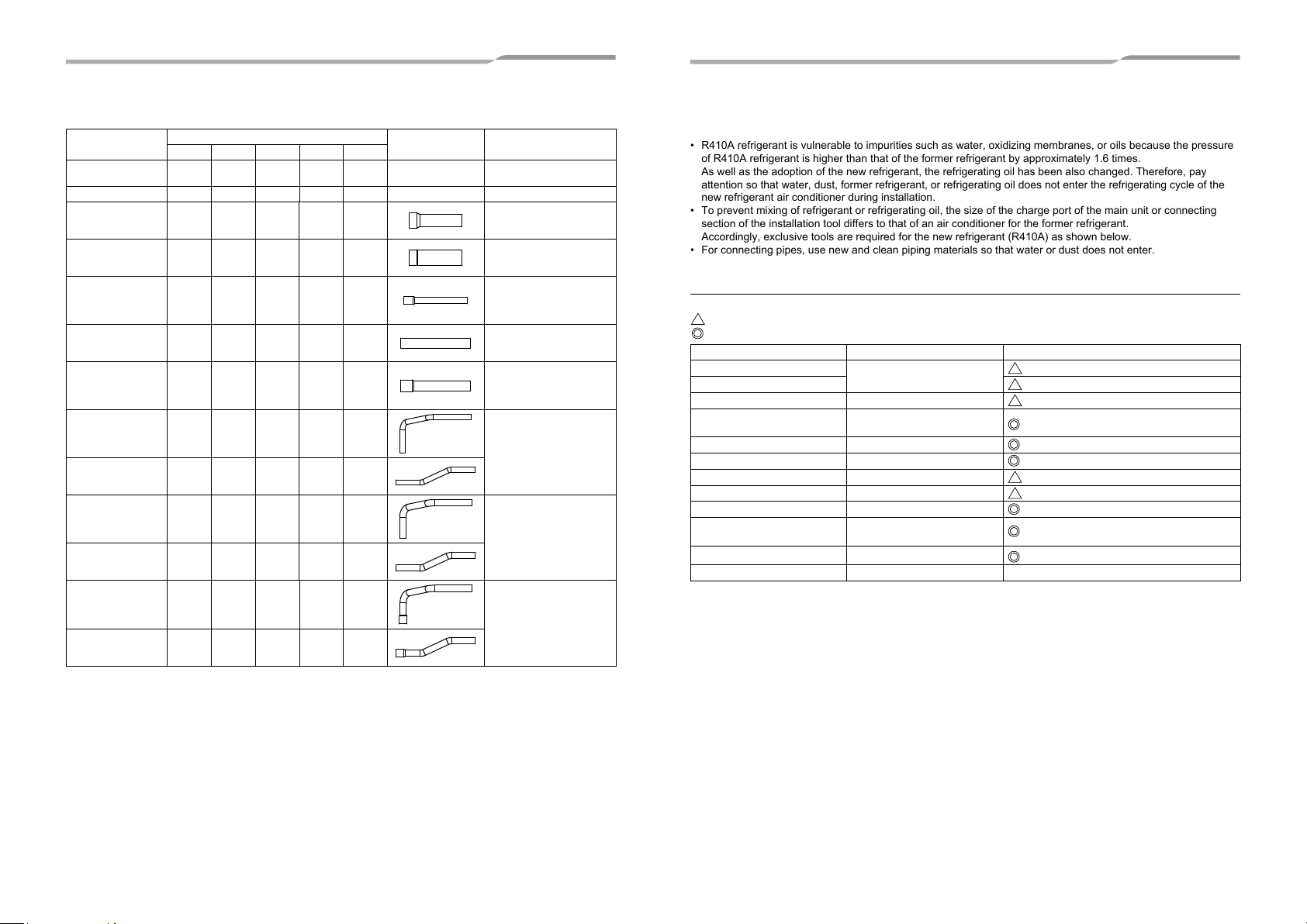
• To prevent mixing of refrigerant or refrigerating oil, the size of the charge port of the main unit or connecting
section of the installation tool differs to that of an air conditioner for the former refrigerant.
Accordingly, exclusive tools are required for the new refrigerant (R410A) as shown below.
• For connecting pipes, use new and clean piping materials so that water or dust does not enter.
2 Accessory parts
Part name
Owner’s Manual 1 1 1 1 1 –
Installation Manual 1 1 1 1 1 – This manual for installer.
Attached pipe
(Ø7/8" both forward
and downward)
Attached pipe
(Ø1 1/8" both forward
and downward)
Attached pipe
(Ø3/4" both forward
and downward)
Attached pipe
(Ø3/4" both forward
and downward)
Attached pipe
(Ø7/8" both forward
and downward)
Attached pipe
(Ø1/2" for draw-out
forward)
Attached pipe
(Ø1/2" for draw-out
downward)
Attached pipe
(Ø5/8" for draw-out
forward)
Attached pipe
(Ø5/8" for draw-out
downward)
Attached pipe
(Ø3/4" for draw-out
forward)
Attached pipe
(Ø3/4" for draw-out
downward)
MAP072 MAP096 MAP120 MAP144 MAP168
11–––
––111
1––––
–11––
–––11
111––
111––
–––1–
–––1–
––––1
––––1
Q’ty
Shape Usage
(Be sure to hand it to the
customers.)
Suction-side gas pipe
Ø1"→Ø7/8" pipe fitting
Suction-side gas pipe
Ø1"→Ø1 1/8" pipe fitting
Discharge-side gas pipe
Ø5/8"→Ø3/4" pipe fitting
* Flare the connector on the
outdoor unit for installation.
Discharge-side gas pipe
* Flare the connector on the
outdoor unit for installation.
Discharge-side gas pipe
Ø3/4"→Ø7/8" pipe fitting
* Flare the connector on the
outdoor unit for installation.
Liquid pipe
* Flare the connector on the
outdoor unit for installation.
Liquid pipe
* Flare the connector on the
outdoor unit for installation.
Liquid pipe
Ø5/8"→Ø3/4" pipe fitting
* Flare the connector on the
outdoor unit for installation.
3 Installation of R410 air conditioner
This air conditioner adopts the HFC refrigerant (R410A) which does not deplete the ozone layer.
• R410A refrigerant is vulnerable to impurities such as water, oxidizing membranes, or oils because the pressure
of R410A refrigerant is higher than that of the former refrigerant by approximately 1.6 times.
As well as the adoption of the new refrigerant, the refrigerating oil has been also changed. Therefore, pay
attention so that water, dust, former refrigerant, or refrigerating oil does not enter the refrigerating cycle of the
new refrigerant air conditioner during installation.
• To prevent mixing of refrigerant or refrigerating oil, the size of the charge port of the main unit or connecting
section of the installation tool differs to that of an air conditioner for the former refrigerant.
Accordingly, exclusive tools are required for the new refrigerant (R410A) as shown below.
• For connecting pipes, use new and clean piping materials so that water or dust does not enter.
■ Required Tools and Cautions on handling
Prepare the tools and equipment listed in the following table before starting the installation work.
: R410A exclusive
: Generic
Tools/equipment Use
Manifold gauge*
Charging hose
Gas leak detector Gas leak check
Vacuum pump with backflow
prevention function
Flare tool Flare machining of pipes
Bender Bending pipes
Refrigerant recovery equipment Refrigerant recovery
Torque wrench Tightening flare nuts
Pipe cutter Cutting pipes
Brazing torch and nitrogen
cylinder
Refrigerant charging scales Charging refrigerant
4 mm hexagon wrench Opening liquid valve
Vacuuming/charging refrigerant
and operation check
Vacuum drying
Braze pipes
Usable if dimensions are adjusted.
Ø1/2" (12.7 mm) and Ø5/8" (15.9 mm)
5-EN 6-EN
Page 5
4 Selection of installation place
Upon customer’s approval, install the air conditioner in a place which satisfies the following conditions:
• Place where it can be installed horizontally.
• Place which can reserve a suffi cient service space for safe maintenance or checks.
• Place where there is no problem even if the drained water overfl ows.
Avoid the following places:
• Salty places (seaside area) or places with much gas sulfi de (hot spring area) (If selecting such a place, special
maintenance is required.)
• Places where oil (including machine oil), steam, oil smoke or corrosive gas is generated.
• Places where an organic solvent is used.
• Chemical plants with a cooling system using liquid carbon dioxide.
• Places where a device generating high frequency (inverter, non-utility generator, medical apparatus, or
communication equipment) is set. (Malfunction or abnormal control of the air conditioner, or interference to
devices listed above may occur.)
• Places where discharged air from the outdoor unit blows against the windows of a neighbour’s house.
• Places unable to bear the weight of the unit.
• Places with poor ventilation.
• The unit will operate down to an outdoor temperature of 13 °F, however considerable performance decrease
will be expected below 5 °F. Therefore please consider installation location/surroundings and system design
when expected to operate between 5 °F and 13 °F.
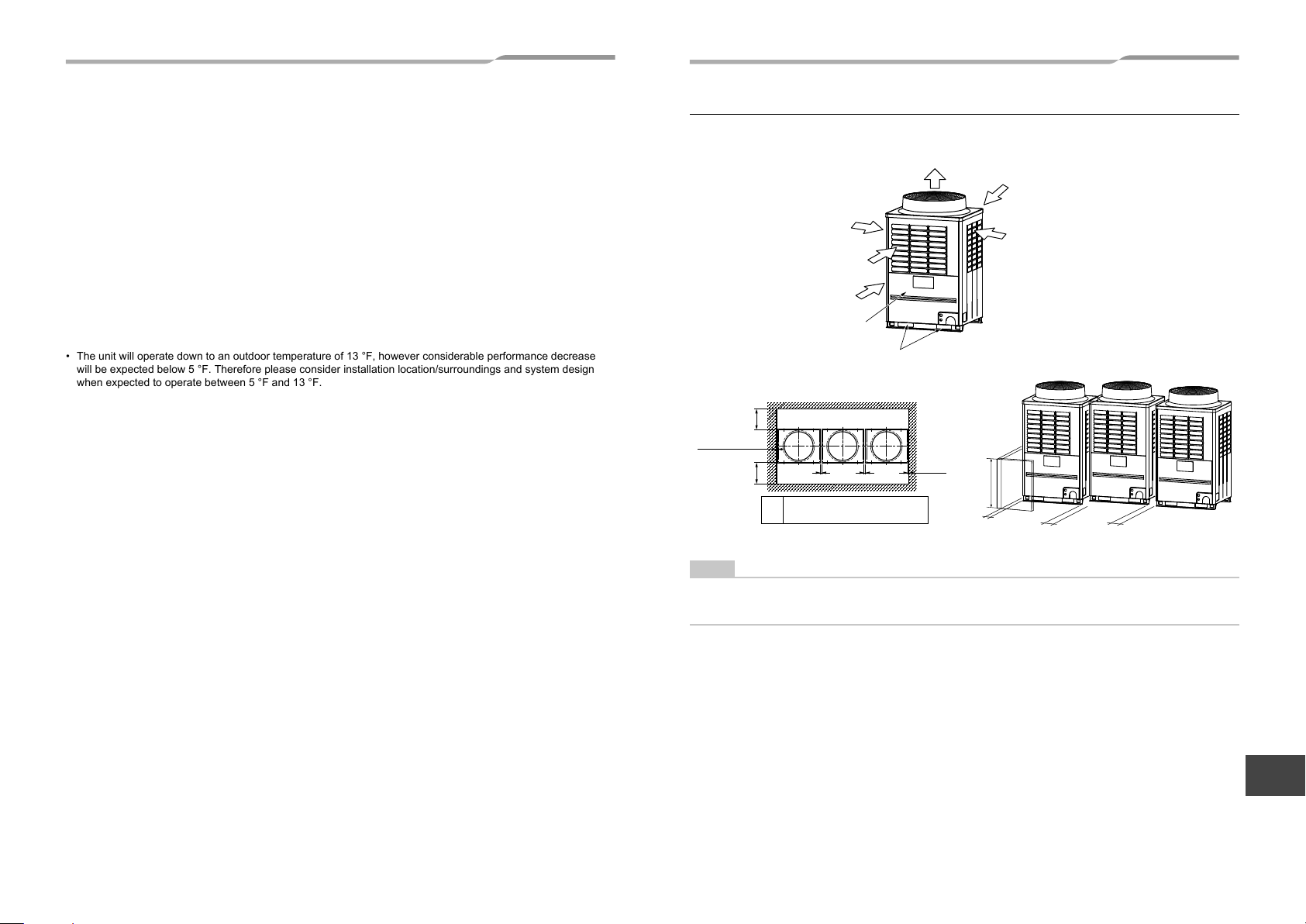
■ Installation space
Leave space necessary for running, installation and servicing.
Air discharge
Air intake
Air intake
Installation/servicing surface
Square hole for handling
(Rear side)
19.7" (500)
or more
0.4" (10) or more
19.7" (500)
or more
(Front side)
Outdoor unit top view
LL
L Recommendation 7.9" (200mm),
at least 0.8" (20mm) or more.
0.4" (10)
or more
31.5" (800)
or less
0.4" (10) or more
Unit: in (mm)
Air intake
Air intake
L L
NOTE
• If there is an obstacle above the outdoor unit, leave a space of 78.7" (2000) or more to the top end of the outdoor
unit.
• If there is a wall around the outdoor unit, make sure that its height does not exceed 31.5" (800).
EN
FR
7-EN 8-EN
– 4 –
Page 6
– 5 –
▼ Combination of outdoor units
Model name
(Standard Model)
MMY-MAP0726FT9P-UL MMY-MAP0726* – –
MMY-MAP0966FT9P-UL MMY-MAP0966* – –
MMY-MAP1206FT9P-UL MMY-MAP1206* – –
MMY-MAP1446FT9P-UL MMY-MAP1446* – –
MMY-MAP1686FT9P-UL MMY-MAP1686* – –
MMY-AP1926FT9P-UL MMY-MAP0966* MMY-MAP0966* –
MMY-AP2166FT9P-UL MMY-MAP1206* MMY-MAP0966* –
MMY-AP2406FT9P-UL MMY-MAP1446* MMY-MAP0966* –
MMY-AP2646FT9P-UL MMY-MAP1446* MMY-MAP1206* –
MMY-AP2886FT9P-UL MMY-MAP1446* MMY-MAP1446* –
MMY-AP3126FT9P-UL MMY-MAP1686* MMY-MAP1446* –
MMY-AP3366FT9P-UL MMY-MAP1206* MMY-MAP1206* MMY-MAP0966*
MMY-AP3606FT9P-UL MMY-MAP1206* MMY-MAP1206* MMY-MAP1206*
MMY-AP3846FT9P-UL MMY-MAP1446* MMY-MAP1206* MMY-MAP1206*
MMY-AP4086FT9P-UL MMY-MAP1446* MMY-MAP1446* MMY-MAP1206*
MMY-AP4326FT9P-UL MMY-MAP1446* MMY-MAP1446* MMY-MAP1446*
MMY-AP4566FT9P-UL MMY-MAP1686* MMY-MAP1446* MMY-MAP1446*
Model name
(Space Saving Model)
MMY-AP192S6FT9P-UL MMY-MAP1206* MMY-MAP0726* –
MMY-AP240S6FT9P-UL MMY-MAP1206* MMY-MAP1206* –
MMY-AP288S6FT9P-UL MMY-MAP1686* MMY-MAP1206* –
MMY-AP336S6FT9P-UL MMY-MAP1686* MMY-MAP1686* –
Unit 1 Unit 2 Unit 3
Header unit Follower unit Follower unit
Unit 1 Unit 2 Unit 3
Header unit Follower unit Follower unit
5 Carrying in the outdoor unit
CAUTION
Handle the outdoor unit carefully, observing the following items.
•
To use a forklift or other machinery for loading/unloading in transportation, insert the fork of the forklift into the
rectangular holes for handling as shown below.
•
To lift up the unit, insert a rope capable of bearing the weight of the unit into the rectangular holes shown below.
Tie the unit from 4 sides.
(Apply padding in positions where the rope comes in contact with the outdoor unit so that no damage is caused
to the outer surface of the outdoor unit.)
(There are reinforcing plates on the side surfaces, so the rope cannot be passed through.)
Correct Incorrect Incorrect
Plaster
board
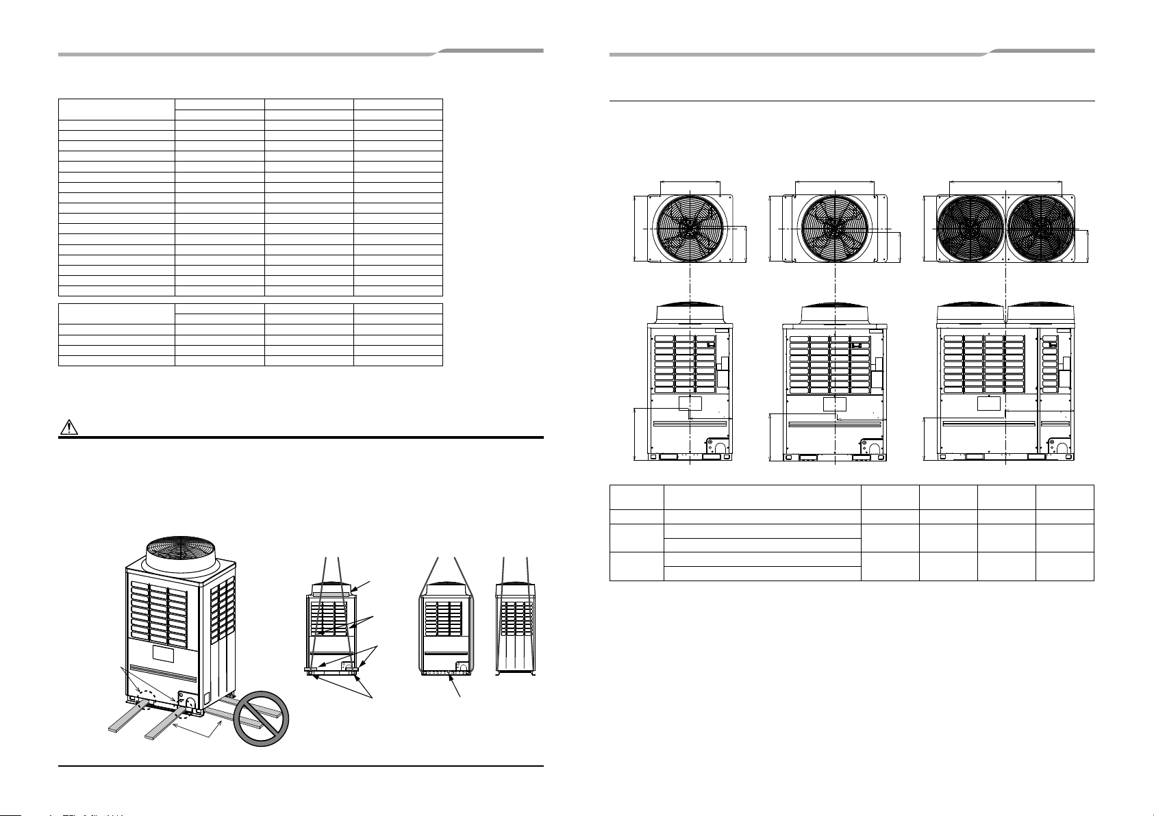
■ Weight center and weight
Unit: in (mm)
◆ Weight center of an outdoor unit
(A) (B) (C)Anchor bolt position
Anchor bolt position
27.6" (700)
29.7" (755)
Z
No. Model type
(A) MAP0726FT9P-UL 20.5" (520) 15.4" (390) 24.0" (610) 600 (272)
MAP0966FT9P-UL
(B)
MAP1206FT9P-UL
MAP1446FT9P-UL
(C)
MAP1686FT9P-UL
Y
Anchor bolt position
X
29.7" (755)
Z
Anchor bolt position
36.2" (920)
Anchor bolt position
51.6" (1310)
Y
29.7" (755)
Anchor bolt position
X
Z
X
(in(mm))Y(in(mm))Z(in(mm))
23.8" (605) 15.7" (400) 23.2" (590) 721 (327)
30.3" (770) 16.3" (415) 22.4" (570) 882 (400)
X
Weight
(lb(kg))
Y
Rope
Rectangular
holes for
handling
Front/Back
Side
Incorrect
Correct
Fork of the
forklift
9-EN 10-EN
Plaster
board
Rectangular
holes for
lifting
Reinforcing
plate
Page 7
6 Installation of the outdoor unit
WARNING
Install the outdoor unit securely in a location where the base can sustain the weight adequately.
If strength is insufficient, the unit may fall down resulting in human injury.
CAUTION
•
Drain water is discharged from the outdoor unit. (Especially while heating)
Install the outdoor unit in a place with good drainage.
•
For installation, be careful of the strength and level of the foundation so that abnormal sounds (vibration or noise)
are not generated.
REQUIREMENT
Installation in a snowfall area
1. Install the outdoor unit on a higher foundation than the snowfall or set up a stand to install the unit so that snowfall
will not affect the unit.
• Set up a stand higher than the snowfall.
• Apply an angled structure to the stand so that drainage will not be prevented. (Avoid using a stand with a fl at
surface.)
2. Mount a snowfall-hood onto the air inlet and the air outlet.
• Leave enough space for the snowfall-hood so that it will not be an obstacle for the air inlet and the air outlet.
Snowfall-hood for air
outlet (locally procured)
Snowfall-hood for air
outlet
(4 faces)
(locally procured)
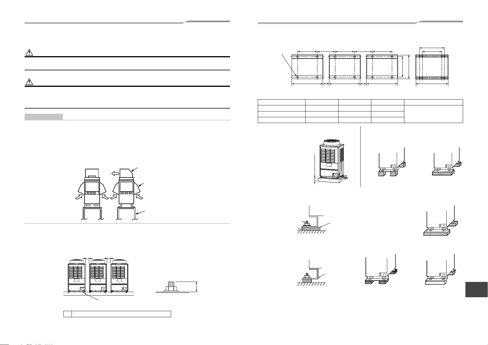
• Anchor bolt positions are as shown below:
Continuous hole
(0.6" × 0.8" (15 × 20)
long hole)
Model type A B C L
MAP0726 27.6" (700) 39.0" (990) –
MAP0966, MAP1206 36.2" (920) 47.6" (1210) –
MAP1446, MAP1686 51.6" (1310) 63.0" (1600) 59.0" (1500)
2. To draw out the refrigerant pipe from the underside,
set the height of the stand to 19.7" (500mm) or more.
L+11.4" (290) L+11.4" (290)
A A A
BL LB
3. Do not use 4 stands on the corner to support the
outdoor unit.
29.7" (755)
B
31.1" (790)
*Only MAP144, MAP168 type has
holes for additional strength.
Recommendation 7.9" (200),
at least 0.8" (20) or more
C*
A
B
Incorrect Correct
19.7" (500mm) or more
4. If vibration-proof rubbers (including vibration-proof blocks) are used, fit them under the whole clamping legs.
Correct
Correct
Stand
(locally procured)
1. To install multiple outdoor units, arrange them with 7.9" (200mm) (recommendation, at least 0.8" (20mm)) or more
spaces in between.
Anchor bolt
Vibration-proof rubber
Install the vibration-proof
rubber so that the bend part
of the fi xing leg is
grounded.
Fix each outdoor unit with M12 anchor bolts at 4 positions. 0.8" (20mm) projection is appropriate for an anchor bolt.
Unit: in (mm)
L L
0.8"
(20)
5. Be careful of the connecting arrangement of the header unit and follower units. Set the outdoor units in order of
Incorrect Incorrect Incorrect
The bend part of the
fi xing leg is not
grounded.
EN
capacity from the one with the largest capacity. (A (Header unit) ≥ B ≥ C)
M12 anchor bolt
4 positions/unit
L
Recommendation 7.9" (200mm), at least 0.8" (20mm) or more.
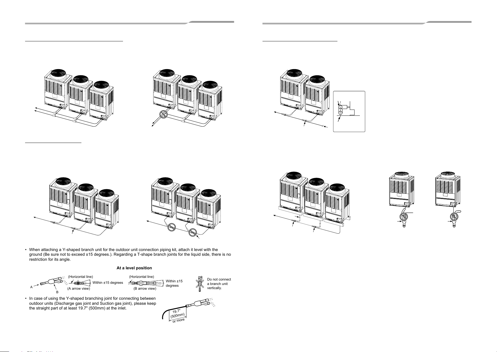
• Be sure to use a header unit for the leading outdoor unit to be connected to the main pipe. (Figure 1, 3 and 6)
• Be sure to use a T-shaped branch joint (RBM-BT14FUL/RBM-BT24FUL: separately purchased) to connect each
outdoor unit.
• Be careful of the direction of the outdoor unit connection piping kit for the liquid side. (As shown in Figure 2, an
FR
outdoor unit connection piping kit cannot be attached so that the refrigerant of the main pipe fl ows directly into
11-EN 12-EN
– 6 –
the header unit.)
Page 8
– 7 –
Discharge side gas piping / Liquid piping
▼ Figure 1
Correct
Main pipe
To the indoor unit
Header unit
A
Follower unit
B
Follower unit
C
▼ Figure 2
Incorrect
Incorrect
To the indoor unit
Header unit
A
Follower unit
B
Main pipe
Follower unit
C
Suction side gas piping
[Inverse connection of a gas-side branch unit]
▼ Figure 3
Correct
Header unit
A
Main pipe
To the indoor unit
Branch unit
Follower unit
B
Follower unit
C
• When attaching a Y-shaped branch unit for the outdoor unit connection piping kit, attach it level with the
ground (Be sure not to exceed ±15 degrees.). Regarding a T-shape branch joints for the liquid side, there is no
restriction for its angle.
At a level position
(Horizontal line) (Horizontal line)
A
(A arrow view) (B arrow view)
B
Within ±15 degrees
• In case of using the Y-shaped branching joint for connecting between
outdoor units (Discharge gas joint and Suction gas joint), please keep
the straight part of at least 19.7" (500mm) at the inlet.
▼ Figure 4
Incorrect
Main pipe
To the indoor unit
Header unit
A
Within ±15
degrees
19.7"
(500mm)
or more
Follower unit
B
To gas-side branch unit
Follower unit
C
Do not connect
a branch unit
vertically.
When drawing pipes downward
▼ Figure 5
Incorrect
Header unit
Main pipe
To the indoor unit
▼ Figure 6
Correct
L-shaped pipe
To gas-side branch unit
A
Suction gas joint
Header unit
A
Follower unit
B
Follower unit
B
A
Follower unit
C
A view
Suction gas joint
Unit
Vertical line
[Vertical connection of branch units]
▼ Figure 7
Incorrect
To gas-side
branch unit
To gas-side
branch unit
13-EN 14-EN
Page 9
7 Refrigerant piping
• After installation, check that the refrigerant gas does not leak.
If the refrigerant gas leaks into the room and comes into contact with fire such as a fan heater, stove, or
kitchen range, noxious gas may be generated.
WARNING
•
If the refrigerant gas leaks during installation, ventilate the room.
If the leaked refrigerant gas comes into contact with fi re, noxious gas may be generated.
•
After installation, check that the refrigerant gas does not leak.
If the refrigerant gas leaks into the room and comes into contact with fi re such as a fan heater, stove, or
kitchen range, noxious gas may be generated.
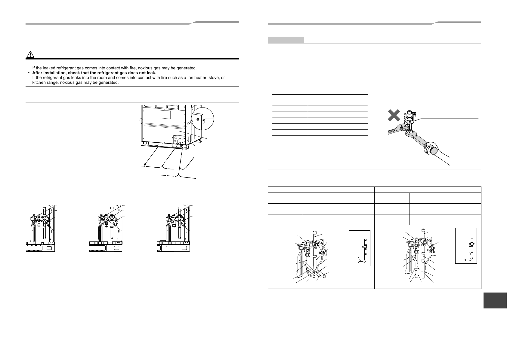
■ Connection of refrigerant pipe
• The service valves are inside the outdoor unit. To
access them, remove the front panel and the piping/
wiring panel. (M5: 9 pcs.)
• As shown in the illustration on the right, the hooks
are at the right and left sides of the front panel. Lift
up and remove the front panel.
• Pipes can be drawn out forward or downward from the
outdoor unit.
• To draw out the pipe forward, draw it out to the
outside via the piping/wiring panel, and leave a space
of 19.7" (500mm) or more from the main pipe
connecting the outdoor unit with the indoor unit,
considering service work or other work on the unit.
(For replacing the compressor, 19.7" (500mm)
or more space is required.)
• To draw out the pipe downward, remove the
knockouts on the base plate of the outdoor unit, draw
(Left
piping)
19.7" (500mm)
or more
Drawing out forward
(Left piping)
(Right
piping)
Drawing out
downward
the pipes out of the outdoor unit, and perform piping on the right/left or rear side. Downward length of the balance
pipe should be 16.4 ft (5m) or less.
Packed valve of liquid side Packed valve of liquid side
Packed valve of
balance pipe
Ball valve of
discharge gas pipe
(MAP072)
Packed valve of liquid side
Ball valve of suction gas side Ball valve of suction gas side
Packed valve of
balance pipe
Ball valve of
discharge gas pipe
(MAP096, 120) (MAP144, 168)
Hook
Front panel
Piping/wiring panel
(Rear piping)
(Right piping)
Ball valve of suction gas side
Packed valve of
balance pipe
Ball valve of
discharge gas pipe
REQUIREMENT
• For a brazing work of the refrigerant pipes, be sure to use nitrogen gas in order to prevent oxidation of the inside
of the pipes; otherwise clogging of the refrigerating cycle due to oxidized scale may occur.
• Use clean and new pipes for the refrigerant pipes and perform piping work so that water or dust does not
contaminate the refrigerant.
• Be sure to use two spanners to loosen or tighten the fl are nut. If a single spanner is used, the required level of
tightening cannot be obtained. Tighten the fl are nut with the specifi ed torque. (If it is hard to loosen or tighten the
fl are nut of the balance pipe or packed valve of the liquid side with two spanners, loosen or tighten the fl are nut
while holding the valve mounting plate with a spanner.)
Unit: ft•lbs (N•m)
Outer dia. of
copper pipe
Tightening torque
Ø1/4 (6.4 mm) 10 to 13 (14 to 18)
Ø3/8 (9.5 mm) 24 to 31 (33 to 42)
Ø1/2 (12.7 mm) 37 to 46 (50 to 62)
Ø5/8 (15.9 mm) 50 to 60 (68 to 82)
Ø3/4 (19.1 mm) 74 to 88 (100 to 120)
Do not apply refrigerating oil to the surface of
the flare.
Ball valve of discharge gas side
Do not clamp the service port
with two spanners, doing so may
damage the service port.
Pipe connection method (Example)
Draw-out forward Draw-out downward
Suction-side gas
pipe
Discharge-side
gas pipe
Liquid pipe
Liquid pipe
Attachment
Attachment
Elbow
Socket
Cut the L-shaped pipe, then braze the
socket procured locally.
Braze the supplied attachment pipe
and elbow procured locally.
Braze the supplied attachment pipe
and socket procured locally.
Discharge-side
gas pipe
pipe
pipe
Pipe
Pipe
Suction-side
gas pipe
Balance
pipe
L-shaped
pipe
Pipe
Socket
Pipe
Suction-side
gas pipe
Section
to be cut
Suction-side gas
pipe
Discharge-side
gas pipe
Liquid pipe
Discharge-side
gas pipe
Liquid pipe
Attachment
pipe
Attachment
pipe
Socket
Cut the L-shaped pipe, then braze the
socket procured locally.
Braze the supplied attachment pipe
and socket procured locally.
Braze the supplied attachment pipe
and socket procured locally.
Pipe
Pipe
Suction-side
gas pipe
Balance
pipe
Pipe
L-shaped
pipe
Socket
Pipe
Socket
Suction-side
gas pipe
Section
to be cut
15-EN 16-EN
– 8 –
EN
FR
Page 10
– 9 –
50
50
For more information, please refer to the engineering data book.
* Permanent operation below 80 % is not recommended.
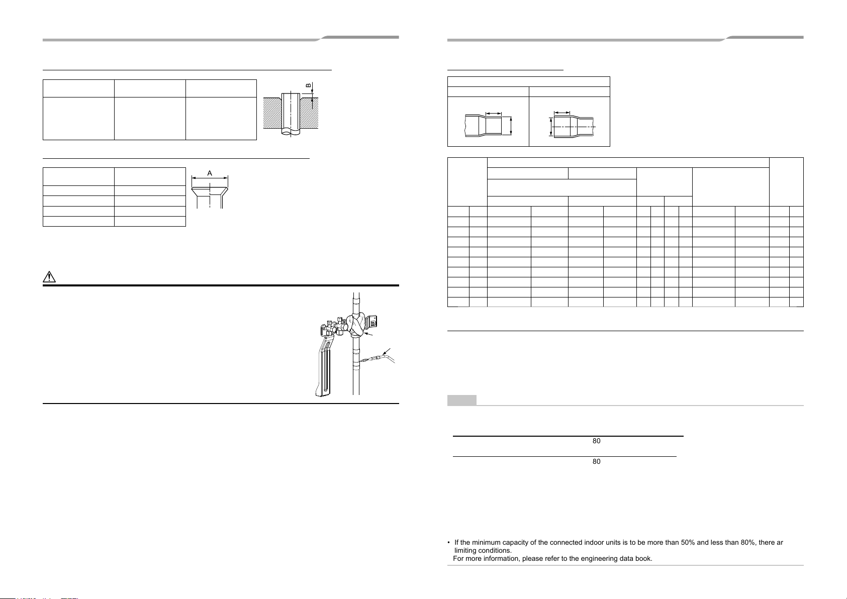
Extruding margin of copper pipe with fl are machining: B (Unit: in (mm))
Copper pipe outer
dia.
3/8" (9.5)
1/2"(12.7)
5/8" (15.9)
3/4" (19.1)
When using R410A
tool
0 - 0.02"
(0 - 0.5)
When using
conventional tool
0.04" - 0.06"
(1.0 - 1.5)
Coupling size of brazed pipe
Connected section
External size Internal size
K
ØC
ØF
G
Extruding margin of copper pipe with fl are tools: A (Unit: in (mm))
0.25" (
0.38" (
0.5" (
0.63" (
0.76" (
0.88" (
1.13" (
1.38" (
1.63" (
+0.0016
−0.0008
+0.0016
−0.0008
+0.0016
−0.0008
+0.0016
−0.0008
+0.0012
−0.0012
+0.0012
−0.0012
+0.0024
−0.0008
+0.0016
−0.0016
+0.0031
−0.0008
Connected section
Min. depth of
+0.04
) 6.45 (
) 9.62 (
) 12.81 (
) 16.00 (
) 19.19 (
) 23.36 (
) 28.75 (
) 35.11 (
) 42.28 (
0.28 7 0.24 6 0.0024" or less 0.06 or less 0.020" 0.50
)
−0.02
+0.04
0.31 8 0.28 7 0.0031" or less 0.08 or less 0.024" 0.60
)
−0.02
+0.04
0.35 9 0.31 8 0.0039" or less 0.10 or less 0.028" 0.70
)
−0.02
+0.04
0.35 9 0.31 8 0.0051" or less 0.13 or less 0.031" 0.80
)
−0.02
+0.03
0.43 11 0.39 10 0.0059" or less 0.15 or less 0.031" 0.80
)
−0.03
+0.03
0.43 11 0.39 10 0.0063" or less 0.16 or less 0.032" 0.82
)
−0.03
+0.06
0.51 13 0.47 12 0.0079" or less 0.20 or less 0.039" 1.00
)
−0.02
+0.04
0.55 14 0.51 13 0.0098" or less 0.25 or less 0.047" 1.20
)
−0.04
+0.08
0.59 15 0.55 14 0.0110" or less 0.28 or less 0.053" 1.35
)
−0.02
insertion
Oval value
thickness
Copper pipe outer
dia.
+0
A
–0.02" (–0.4)
3/8" (9.5) 0.52" (13.2)
1/2"(12.7) 0.65" (16.6)
5/8" (15.9) 0.78" (19.7)
3/4" (19.1) 0.94" (24.0)
* When using the conventional flare tool, to connect R410A pipes with flaring, make a margin approx.
0.02" (0.5 mm) longer than that of an R22 pipe so that the flare size matches the one specified. It is convenient
to use a copper pipe gauge for size adjustment of the extruding margin.
CAUTION
Wrap the ball valve in a wet cloth to keep it cool and prevent the heat from the
torch from damaging it when connecting the pipe to the ball valve on the gas line.
Standard
outer dia.
of connected
copper pipe
External size Internal size
Standard outer dia.
(Allowable difference)
CFKG
in mm in mm in mm in mm in mm in mm in mm
Ø1/4 6.35 1/4"(±0.0012) 6.35(±0.03)
Ø3/8 9.52 3/8"(±0.0012) 9.52(±0.03)
Ø1/2 12.7 1/2"(±0.0012) 12.70(±0.03)
Ø5/8 15.88 5/8"(±0.0012) 15.88(±0.03)
Ø3/4 19.05 3/4"(±0.0012) 19.05(±0.03)
Ø7/8 22.2 7/8"(±0.0012) 22.22(±0.03)
Ø1-1/8 28.58 1-1/8"(±0.0012) 28.58(±0.04)
Ø1-3/8 34.92 1-3/8"(±0.0012) 34.90(±0.04)
Ø1-5/8 41.28 1-5/8"(±0.0012) 41.28(±0.05)
■ Selection of pipe size
Cloth
Torch
17-EN 18-EN
◆ Capacity code of indoor and outdoor units
Selection of pipe material
• For the indoor unit, the capacity code is decided at each capacity type. (Table 1)
• The capacity codes of the outdoor units are decided at each capacity type. The maximum number of connectable
indoor units and the total value of capacity codes of the indoor units are also decided. (Table 2)
NOTE
Compared with the capacity code of the outdoor unit, the total value of capacity codes of the connectable indoor
units differs based on the height difference between the indoor units.
When the height difference between the indoor units is 49 ft (15 m) or less
Total indoor capacity code must be between 80% and 135% of the capacity of the outdoor unit.
When the height difference between the indoor units is over 49 ft (15 m)
Total indoor capacity code must be between 80% and 105% of the capacity of the outdoor unit.
• If MMU-AP0072H2UL-1 or MMU-AP0122H2UL is included in the system, total indoor capacity code must be
between 80% and 100% of outdoor unit capacity.
• If MMD-AP
• when the height difference between the indoor units is over 49 ft (15 m): between 80% and 105%
• when the height difference between the indoor units is 49 ft (15 m) or less: between 80% and 120%
* If the system confi gure only the limited indoor unit type and limited number of connection indoor unit, total indoor
capacity code up to 150% of the outdoor capacity code is available when the height difference between the
indoor units is 49 ft (15 m) or less.
• If the minimum capacity of the connected indoor units is to be more than 50% and less than 80%, there are
limiting conditions.
For more information, please refer to the engineering data book.
BH is included in the system, total indoor capacity code must be,
∗∗∗
Min.
of
coupling
Page 11

Table 1
Indoor unit capacity type
007 type 7.5
009 type 9.5
012 type 12
015 type 15.4
018 type 18
021 type 21
024 type 24
027 type 27
030 type 30
036 type 36
042 type 42
048 type 48
054 type 54
072 type 72
096 type 96
Indoor capacity code
(Equivalent to capacity)
Table 2
Outdoor unit
capacity type
Outdoor unit
capacity code
Maximum number of indoor units (*1)
Height difference between indoor units
49 ft (15 m) or less Over 49 ft (15 m)
072 type
096 type
120 type
144 type
168 type
192 type
216 type
72 12 10
96 16 13
120 21 16
144 25 19
168 30 23
192 34 26
216 38 29
240 type 240 42 32
264 type 264 46 36
288 type 288 50 39
312 type 312 55 43
336 type 336 60 47
360 type 360 63 49
384 type 384 64 52
408 type 408 64 55
432 type 432 64 59
456 type 456 64 63
* For combination of the outdoor units, refer to “Combination of outdoor units”.
(*1) : Under centralized control maximum 54 units.
Outdoor unit
(1)
Balance
pipes
Ø3/8"
Liquid pipe
Discharge-side
Suction-side
(3) Main piping
gas pipe
gas pipe
Header
unit A
(9)
Follower
unit B
(2)
First branch
(9)
Follower
unit C
(1)(1)(1)
(4)
(7)(7)
(10) Single port type Flow
selector unit
(8) Branching header
(7) Y-shaped branching joint
(4)
(10)
(5)
(7)
(4)
(6)
(6)
(10)
(5)
(7)
(4)
(4)
(10)
(5)
Indoor unit
(6)
(4)
(10)
(4)
(5)
(10) Multi port type Flow selector unit
(7)
(4)*2
(4)*2
(6)
(4)*2
(7)
(4)*2
(4)*2
(6) (6) (6)
(7)
(6)
(6)
(6) (6)
Cooling only Cooling only
(7)
EN
FR
19-EN 20-EN
– 10 –
Page 12

– 11 –
(1) Outdoor unit connecting pipe
Outdoor unit capacity type (*1) Balance pipe side Suction gas side
072 type, 096 type Ø3/8" Ø7/8" Ø3/4" Ø1/2"
120 type Ø3/8" Ø1-1/8" Ø3/4" Ø1/2"
144 type Ø3/8" Ø1-1/8" Ø7/8" Ø5/8"
168 type Ø3/8" Ø1-1/8" Ø7/8" Ø3/4"
(2) Connecting pipe between outdoor units
Total capacity code of the outdoor
units at downstream side (*1) (*7)
336 Ø1-3/8" Ø1-1/8" Ø7/8"
360 or more Ø1-5/8" Ø1-1/8" Ø7/8"
Suction gas side
Discharge
(3) Main pipe
Total capacity code of all
outdoor units
072, 096 Ø7/8" Ø3/4" Ø1/2"
120 Ø1-1/8" Ø3/4" Ø1/2"
144 Ø1-1/8" Ø7/8" Ø5/8"
168, 192 Ø1-1/8" Ø7/8" Ø3/4"
216, 240 Ø1-3/8" Ø1-1/8" Ø3/4"
264, 288, 312, 336 Ø1-3/8" Ø1-1/8" Ø7/8"
360 or more Ø1-5/8" Ø1-3/8" Ø7/8"
Suction gas side
Discharge
(4) Branching pipe
Total capacity code of indoor units
at downstream side (*1) (*2) (*3) (*8)
Below 61 Ø5/8" Ø1/2" Ø3/8"
61 to below 115.5 Ø7/8" Ø3/4" Ø1/2"
115.5 to below 153.5 Ø1-1/8" Ø7/8" Ø5/8"
153.5 to below 191.5 Ø1-1/8" Ø7/8" Ø3/4"
191.5 to below 239 Ø1-3/8" Ø1-1/8" Ø3/4"
239 to below 334 Ø1-3/8" Ø1-1/8" Ø7/8"
334 or more Ø1-5/8" Ø1-3/8" Ø7/8"
Suction gas side
Discharge
(5) FS unit and indoor unit connection pipe
Indoor unit capacity code Gas side Liquid side
007 to 012 type Ø3/8" Ø1/4"
015 to 018 type Ø1/2" Ø1/4"
021 to 054 type Ø5/8" Ø3/8"
072 to 096 type Ø7/8" Ø1/2"
(6) Branching and indoor unit connection pipe
Indoor unit capacity code Gas side Liquid side
007 to 012 type
015 to 018 type
Pipe length
(Actual length)
Pipe length
(Actual length)
021 to 054 type Ø5/8" Ø3/8"
072 to 096 type Ø7/8" Ø1/2"
49 ft or less Ø3/8" Ø1/4"
Over 49 ft Ø1/2" Ø3/8"
49 ft or less Ø1/2" Ø1/4"
Over 49 ft Ø5/8" Ø3/8"
gas side
gas side
gas side
Discharge
gas side
Liquid side
Liquid side
Liquid side
Liquid side
(7) Y-shaped branching joint (*3) (*4)
Total capacity code of indoor units
on downstream side from
Y-shaped branching joint (*4) (*5)
Below 61 RBM-BY55FUL RBM-BY55UL
61 to below 134.5 RBM-BY105FUL RBM-BY105UL
134.5 to below 239 RBM-BY205FUL RBM-BY205UL
239 or more RBM-BY305FUL RBM-BY305UL
For 3 pipe For 2 pipe
Model name
(8) Branching header
Total capacity code of the indoor units
on downstream side from
branching header (*4) (*5) (*6)
For 4 branching
For 8 branching
Below 134 RBM-HY1043FUL RBM-HY1043UL
134 to below 240 RBM-HY2043FUL RBM-HY2043UL
Below 134 RBM-HY1083FUL RBM-HY1083UL
134 to below 240 RBM-HY2083FUL RBM-HY2083UL
For 3 pipe For 2 pipe
Model name
(9) Outdoor unit connection piping kit
Total capacity code of the outdoor
units at downstream side (*1) (*7)
Below 247 RBM-BT14FUL
247 or more RBM-BT24FUL
Model name
(10) Flow Selector unit (*9)
Single port type (*10)
Total capacity code of outdoor units
on downstream side from FS unit
Below 38 RBM-Y0383FUL
38 to below 61 RBM-Y0613FUL
61 to 96 or less RBM-Y0963FUL
Multi port type (*11)
Total capacity code of outdoor units
on downstream side from FS unit
Below 61
(*1) : The capacity code of outdoor unit and indoor unit, please refer to “Capacity code of indoor and outdoor units”.
(*2) : If the size of the pipe to be selected is larger than the size of the main pipe, please use the same pipe size as the main pipe.
(*3) : Two pipes in downstream of FS unit and cooling only indoor unit use liquid pipe and suction gas pipe.
(*4) : The first branching joint, select at capacity code of outdoor unit.
(*5) : If the total capacity code of indoor units exceed the capacity code of outdoor unit, select the size from the capacity code of the outdoor unit.
(*6) : For one line pipe line of header branching, total 57 capacity code of indoor units is connectable.
If connecting the branching header to the first branch section with the capacity code of outdoor unit is more than 114 (kBtu/h) and less than
247 (kBtu/h), use the RBM-2043FUL (4 branch), and RBM-HT2083FUL (8 branch).
Also, the branching header cannot be used for the first branch section when the capacity code of outdoor unit is more than 247 (kBtu/h).
(*7) : The main pipe is the starting point. The follower unit side is the downstream side.
(*8) : Selection piping is the starting point. The indoor unit side is the downstream side.
(*9) : If the code of outdoor unit is over 408, “Flow Selector unit” is available for only Multi port type.
(*10) : The group connection of the multiple indoor units is possible up to maximum 8 units, and it is possible only within one FS unit.
(*11) : The group connection of the multiple indoor units is possible up to 8 units if one remote controller is used, and it is possible up to 7 units if two
remote controllers are used. The group connection of the multiple indoor units is possible only within one branch.
No. of branch Model name
Model name
4 RBM-Y0613F4PUL
6 RBM-Y0613F6PUL
21-EN 22-EN
Page 13

CAUTION
Please use the appropriate pipe when the pipe size is Ø3/4 or more. (Table 3)
Outer diameter
Inch mm Inch mm OK OK
Ø1/4" 6.35 0.03 0.80 OK OK
Ø3/8" 9.52 0.03 0.80 OK OK
Ø1/2" 12.7 0.04 1.00 OK OK
Ø5/8" 15.88 0.04 1.00 OK OK
Ø3/4" 19.05 0.04 1.00 NG OK
Ø7/8" 22.2 0.04 1.00 NG OK
Ø1-1/8" 28.58 0.04 1.00 NG OK
Ø1-3/8" 34.92 0.05 1.20 NG OK
Ø1-5/8" 41.28 0.06 1.40 NG OK
Minimum
wall thickness
Temper
Soft Hard, Half hard
■ Allowable length of refrigerant pipes and allowable height
difference between units
C
Follower unit
(c)
Lc
Lb
Outdoor unit connecting
LO
Height
difference
between
outdoor units
L1
Outdoor unit
A
Header
Follower
unit
(b)(a)
La
LA
Outdoor unit
connection
B
unit
Height
difference
between
outdoor and
indoor units:
H1
Main piping
L3
Branching pipe
Indoor unit connecting pipe
a
f
Indoor unit
L4
L5
Flow
Selector
unit
i
Indoor unit
L9
Indoor unit connecting pipe
p
Indoor unit
Branching header
L2
bc
g
The longest piping length:
The longest piping length from the first branch: Li
The longest piping length in Flow selector unit group : Ln
L6 L7
d
h
L
L8
e
m
(m)
j
Flow Selector unit (Multi port type)
Y-shaped branching joint
s
q
r
H4
tnioj gnihcnarb depahs-Ygnihcnarb tsriF
k
n
(n)
t
l
o
(o)
EN
Height difference between indoor units H2
u
FR
23-EN 24-EN
– 12 –
Page 14

– 13 –
(*1)
(*2)
(*1) : In case without central control. It is up to 54 units in case with central control.
(*2) : If the system configure only the limited indoor unit type and limited number of connection indoor unit, total indoor capacity code up to 150%
of the outdoor capacity code is available when the height difference between the indoor units is 49 ft (15m) or less.
* Permanent operation and heating operation below 80 % is not recommended.
For more information, please refer to the engineering data book.
◆ System restrictions
Max. No. of combined outdoor units 3 units
Max. capacity of combined outdoor units 38 ton
Max. No. of combined indoor units 64 units (*2)
Max. capacity of combined indoor units
H2 ≤ 49 ft (15m)
135% of outdoor units’ capacity
150% of outdoor units’ capacity (*1)
H2 > 49 ft (15m) 105% of outdoor units’ capacity
(*1) : If the system configure only the limited indoor unit type and limited number of connection indoor unit, total indoor capacity code up to 150%
of the outdoor capacity code is available when the height difference between the indoor units is 49 ft (15m) or less.
(*2) : In case without central control. It is up to 54 units in case with central control.
• If the minimum capacity of the connected indoor units is to be more than 50% and less than 80%, there are limiting conditions.
For more information, please refer to the engineering data book.
◆ Cautions for installation
• Set the outdoor unit fi rst connected to the branching pipe to the indoor units as the header unit.
• Install the outdoor units in order of their capacity codes : (A) header unit ≥ (B) ≥ (C)
• Y-shaped branching joint must be installed horizontally.
• When piping to outdoor units using outdoor unit connection piping kits, intersect the pipes to the outdoor unit
and those to indoor units at a right angle as shown in fi gure 1 on “6. Installation of the outdoor unit”.
Do not connect them as in fi gure 2 on “6. Installation of the outdoor unit”.
25-EN 26-EN
◆ Allowable length and allowable height difference of refrigerant piping
Item
Total extension of pipe
(liquid pipe, real length)
Farthest piping length L (*1) (*3) (*7)
Max. equivalent length of
Main piping (*12)
Pipe
length
Height
difference
<In case of connecting single port type Flow Selector unit and a branch of Multi port type Flow Selector unit to the indoor units.>
Maximum equivalent length indoor units in group control by one single port Flow
Selector unit Ln
Maximum real length between
Flow Selector unit and indoor unit (*2)
Height difference between indoor units in group control by one Flow Selector
unit H4
(*1) : Farthest outdoor unit from the first branch: (C), farthest indoor unit: (o)
(*2) : If FS unit is connected to multiple indoor units, connect wires of FS unit to one of the indoor unit with main remote control.
(*3) : Allowable values for length equivalent to furthest pipe are shown below and they vary according to capacity rank of outdoor unit.
(*4) : When system capacity is greater than 22 ton, height difference between indoor units is limited to 10 ft. If the piping exceeds 10 ft with a
(*5) : Ensure that the header unit is installed below all connected follower outdoor unit(s).
(*6) : 131 ft is possible for a system that uses only the flow selector unit (multi port type), whose all the indoor units are 030 type or higher, and
(*7) : As for 36 to 38 ton, contact our agent.
(*8) : If the height difference (H2) between indoor units exceed 10 ft, set 164 ft or less.
(*9) : Total charging refrigerant is 308 lbs or less.
(*10) : The total piping length in one FS unit in case of branching to 4 : 394 ft (p + q + r + s + t + u), In case of branching to 6 : 590 ft.
(*11) : Length of whole pipe should be shorter than 164 ft in one branch.
(*12) : As for 34 to 38 ton, contact our agent.
(*13) : Extension up till 295 ft is possible with conditions below ;
- Outdoor temperature Cooling : 50 - 115 ºF (DB)
Heating : 23 - 59 ºF (DB)
Simultaneous operating : 45 - 77 ºF (DB)
- Equivalent length of farthest piping from first branching Li < 164 ft
- Actual length of main piping L1 < 328 ft
- Height difference between indoor units : < 10 ft
- Single outdoor unit, and up to 14 ton
- Minimum capacity of connectable indoor unit 036 type or larger
- Height difference between FS unit : < 1.6 ft
- Diversity : 90 - 100%
Farthest equivalent piping length from the
first branch Li (*1)
Farthest equivalent piping length between outdoor units LO (*1) 49 LA + Lc (LA + Lb)
maximum equivalent piping length of pipes connected to outdoor
units
Maximum real length of terminal branching section to indoor units 98 a + f, b + g, c + h, d + i, e + j, k, l
Maximum real length of between
Flow Selector unit and indoor unit
Maximum equivalent length between branching section 164 L2, L3, L4, L8, L9
Height between outdoor
and indoor units H1 (*7)
Height between indoor
units H2 (*7)
Height between outdoor units H3 (*5) 16 –
6 to 14 ton : 607 ft, 16 to 26 ton : 640 ft, 28 to 34 ton : 656 ft
capacity greater than 22 ton there may be a case of capacity shortage in cooling.
Possible product failure may occur if header unit is installed above any follower unit(s).
working ambient temperature is 32 ºF or higher.
H2
H2 ≤ 10 ft
Upper outdoor units
Lower outdoor units 98 (*6) –
Upper outdoor units 131 –
Lower outdoor units (*4) 49 –
Single port type 49
Multi port type 164 s + t , s + u ≤ 164 ft
Below 26 ton 984
26 ton or more 3281 (*9)
Equivalent length 656 (*2)
Real length 591
Equivalent length 328
>10 ft
Real length 279
Equivalent length 394
Real length 328
H1 > 10 ft 164
H1
<10 ft 213
Single port type 49 f, g, h, i, j
Multi port type
Allowable
value (ft)
33 Lc (La , Lb)
164
(*10) (*11)
230
(*8) (*13)
98 L6 + L7 + L8 + o
1.6 –
LA + La + Lb + Lc + L1 + L2 + L3 +
L4 + L5 + L6 + L7 + L8 + L9 + a + b +
c + d + e + f + g + h + i + j + k + l +
m + n + o+ p + q + r + s + t + u
L3 + L4 + L5 + L6 + L7 + L8 + o
(Ex.) In case of wiring to the indoor
Pipes
LA + Lc + L1 + L3 + L4 +
L5 + L6 + L7 + L8 + o
L1
p, q, r, s + t, s + u
–
unit (m): L6 + m ≤ 49 ft
In case of wiring to the indoor
unit (n): L6 + L7 + n ≤ 49 ft
Page 15

■ Airtightness test
After the refrigerant piping has been finished, execute an airtight test.
For an airtight test, connect a nitrogen gas canister as shown in the figure on this page and apply pressure.
• Be sure to apply pressure from the service ports of the packed valves (or ball valves) at the suction gas side,
■ Vacuum drying
• Be sure to use a vacuum pump equipped with the counter-flow prevention function so that oil in the pump will
not flow back into piping for air conditioners. (If oil in the vacuum pump enters in the air conditioner with R410A
refrigerant, a problem may be caused in the refrigerating cycle.)
discharge gas side, liquid side and balance pipe side.
• An airtight test can only be performed at the service ports at the suction gas side, discharge gas side, liquid side
and balance pipe side.
• Close the valves fully at the suction gas side, discharge gas side, liquid side and balance pipe side. As there is
a possibility that the nitrogen gas will enter into the cycle of outdoor units, re-tighten the valve rods at the liquid
side and balance pipe side before applying pressure.
• For each refrigerant line, apply pressure gradually in steps at the suction gas side, discharge gas side, liquid
side and balance pipe side.
Be sure to apply pressure at the suction gas side, discharge gas side, liquid side and balance pipe side.
WARNING
Never use oxygen, flammable gases, or noxious gases in an airtight test.
Low pressure
To gauge
manifold
Liquid-side
service port
Liquid-side
valve
Piping at site
To
outdoor
unit
Service port
of discharge
gas side
Ball valve of
discharge
gas side
Service port of suction gas side
Ball valve of suction gas side
To outdoor
unit
Piping
at site
Packed valve details
To outdoor unit
Service
To
port
gauge
of balance
manifold
pipe side
To
outdoor
unit
Packed
valve
Piping
at site
of balance
pipe side
Piping
at site
Connected to
indoor unit
Main
piping
Brazed
Fully
closed
Fully
closed
Fully
closed
Connected to
other follower units
Suction gas side valve
fully closed
Header outdoor unit
Service port
Ø6.4 copper pipe
Service port
Discharge gas side valve
fully closed
Service port
Liquid side valve fully closed
Service port
Balanced pipe side valve
fully closed
Able to detect a serious leakage
1. Apply pressure 43.5 psi (0.3 MPa) for 5 minutes or more.
2. Apply pressure 217.5 psi (1.5 MPa) for 5 minutes or more.
Available to detect slow leakage
3. Apply pressure 601 psi (4.15 MPa) for approx. 24 hours.
• If there is no pressure decrease after 24 hours, the test is passed.
NOTE
However, if the environmental temperature changes from the moment of applying pressure to 24 hours after that,
the pressure will change by about 1.45 psi (0.01 MPa) per 1.8 °F. Consider the pressure change when checking
the test result.
REQUIREMENT
When pressure decrease is detected in steps 1-3, check the leakage at the connecting points.
Check the leakage using a foaming agent or other measures and seal the leak with re-brazing, flare retightening
or other methods. After sealing, execute an airtight test again.
gauge
High pressure
gauge
L
V
VH
Reducing
valve
Ø6.4
copper
pipe
Gauge
manifold
Nitrogen
gas
After finishing the airtight test and discharging nitrogen gas, connect the gauge manifold to the service ports of the
suction gas side, discharge gas side, liquid side and balance pipe side and connect a vacuum pump as shown
in the figure below. Be sure to perform vacuuming for the suction gas side, discharge gas side, liquid side and
balance pipe side.
To gauge
manifold
Liquid-side
service port
Liquid-side
valve
Piping at site
Service port of suction gas side
Ball valve of suction gas side
To
outdoor
unit
Service port
of discharge
gas side
Ball valve of
discharge
gas side
To outdoor
unit
Piping
at site
Packed valve details
To outdoor unit
To
gauge
manifold
Piping
at site
Piping
at site
Service
port
of balance
pipe side
To
outdoor
unit
Packed
valve
of balance
pipe side
Connected to
indoor unit
Fully
closed
Fully
closed
Fully
closed
Connected to
other follower
units
Suction gas side valve
Main
pipe
Brazed
fully closed
Header outdoor unit
Discharge gas side valve
fully closed
Balanced pipe side valve fully
closed
Low pressure
Service port
Service port
Service port
Liquid side valve fully
closed
Service port
gauge
High pressure
gauge
V
L
V
H
Gauge
manifold
P
Vacuum
pump
• Use a vacuum pump with a high vacuuming degree [14.6 psi (5Torr, -755mmHg)] and large exhaust gas amount
(40L/minute or larger).
• Perform vacuuming for 2 or 3 hours, though the time differs depending on the pipe length. Check that all the
valves at the suction gas side, discharge gas side, liquid side and balance pipe side are fully closed.
• If the pressure does not reach 14.6 psi or less even after vacuuming for over 2 hours, continue vacuuming for 1
hour or more. If the pressure does not reach 14.6 psi after 3 hours of vacuuming, stop vacuuming and check for
air leakage.
• If the pressure reaches 14.6 psi or less after vacuuming for 2 hours or more, close the valves VL and VH on
the gauge manifold fully and stop the vacuum pump. Leave it as it is for 1 hour to confi rm that the vacuuming
degree does not change.
If the degree of vacuum loss is large, moisture may remain in the pipes. In that case, inject dry nitrogen gas and
apply pressure to 7.3 psi and perform vacuuming again.
• After fi nishing the above procedure of vacuuming, exchange the vacuum pump with a refrigerant canister and
advance to the additional charging of refrigerant.
■ Adding refrigerant
After finishing vacuuming, exchange the vacuum pump with a refrigerant canister and start additional
charging of refrigerant.
1. Refrigerant charge amount at shipment from the factory does not include the refrigerant for pipes at the local site.
For refrigerant to be charged in pipes at the local site, calculate the amount and charge it additionally.
Model name Refrigerant amount charged in factory
0726FT9P-UL
MMY-MAP
0966FT9P-UL
1206FT9P-UL
1446FT9P-UL
1686FT9P-UL
24.3 lbs
EN
FR
2. Additional refrigerant charge, please calculate from the calculation of additional refrigerant charge amount.
27-EN 28-EN
– 14 –
Page 16

– 15 –
■ Calculation of additional refrigerant charge amount
Additional refrigerant charge amount (lbs) = [1] + [2]
[1]. Compensation by capacity of outdoor unit (Table1)
[2]. (Actual length of liquid pipe × Additional refrigerant charge amount per liquid pipe 1 ft (Table2)) × 1.3
NOTE
If the additional refrigerant amount indicates minus as the result of calculation, use the air conditioner without
additional refrigerant.
(Table1) Compensation by capacity of outdoor unit
Outdoor unit
capacity type
072 type MMY-MAP0726FT9P-UL 4.4
096 type MMY-MAP0966FT9P-UL 6.6
120 type MMY-MAP1206FT9P-UL 17.6
144 type MMY-MAP1446FT9P-UL 24.3
168 type MMY-MAP1686FT9P-UL 30.9
192 type MMY-AP1926FT9P-UL 8.8
216 type MMY-AP2166FT9P-UL 13.2
240 type MMY-AP2406FT9P-UL 22.1
264 type MMY-AP2646FT9P-UL 26.5
288 type MMY-AP2886FT9P-UL 30.9
312 type MMY-AP3126FT9P-UL 33.1
336 type MMY-AP3366FT9P-UL 13.2
360 type MMY-AP3606FT9P-UL 24.3
384 type MMY-AP3846FT9P-UL 28.7
408 type MMY-AP4086FT9P-UL 30.9
432 type MMY-AP4326FT9P-UL 33.1
456 type MMY-AP4566FT9P-UL 37.5
Outdoor unit
capacity type
192 type MMY-AP192S6FT9P-UL 8.8
240 type MMY-AP240S6FT9P-UL 22.1
288 type MMY-AP288S6FT9P-UL 30.9
336 type MMY-AP336S6FT9P-UL 37.5
Model name
(Standard Model)
Model name
(Space Saving Model)
(Table2) Actual length of liquid pipe × Additional refrigerant charge amount per liquid pipe 1 ft
Liquid pipe outer diameter (in) Ø1/4" Ø3/8" Ø1/2" Ø5/8" Ø3/4" Ø7/8"
Additional refrigerant amount lbs/ft 0.017 0.037 0.071 0.108 0.168 0.235
Compensation by
capacity type outdoor unit
capacity type outdoor unit
(lbs)
Compensation by
(lbs)
Example:
120 type (MMY-MAP1206FT9P-UL)
L1
Pipe Liquid pipe size Actual Piping length
L1 Ø1/2" 30 ft
L2 Ø1/2" 15 ft
L3 Ø3/8" 10 ft
L4 Ø3/8" 10 ft
L5 Ø3/8" 5 ft
L6 Ø1/4" 10 ft
L7 Ø1/4" 10 ft
Additional refrigerant charge amount(lbs) = [1] + [2]
= 17.6 lbs + 5.798 lbs
= 23.40 lbs
[1]. Compensation by capacity of outdoor unit (Table1)
= Compensation by 120 type
= 17.6 lbs
[2]. (Actual length of liquid pipe × Additional refrigerant charge amount per liquid pipe 1 ft (Table2)) × 1.3
= (Lx × 0.017 lbs/ft + Ly × 0.037 lbs/ft + Lz × 0.071 lbs/ft) × 1.3
= ((L6+L7) × 0.017 lbs/ft + (L3+L4+L5) × 0.037 lbs/ft+(L1+L2) × 0.071 lbs/ft) × 1.3
= ((20 ft) × 0.017 lbs/ft + (25 ft) × 0.037 lbs/ft+(45 ft) × 0.071 lbs/ft) × 1.3
= (0.34 lbs + 0.925 lbs + 3.195 lbs) × 1.3
= (4.46 lbs ) × 1.3
= 5.798 lbs
Lx : Actual total length of liquid pipe Ø1/4" (ft)
Ly : Actual total length of liquid pipe Ø3/8" (ft)
Lz : Actual total length of liquid pipe Ø1/2" (ft)
L2
L4 L5 L6 L7
L3
048 type 036 type 018 type 015 type
29-EN 30-EN
Page 17

1. All service valves on the outdoor units should remain fully closed.
2. R410A refrigerant should be added (in liquid state) at the liquid line service port on the header unit.
3. If the calculated amount of refrigerant can added to the system, the charging process is finished.
4. If the total calculated amount of refrigerant cannot be added to the system, close the valve on the refrigerant
bottle, move the charging hose from the liquid line service port to the suction line service port.
5. Open the suction and liquid service valves on the header unit and start the system in cooling mode.
6. Slowly open the valve on the refrigerant bottle and carefully release liquid refrigerant into the suction service
port.
7. If the total calculated charge amount is added completely to the system, the charging process is finished.
■ Full opening of the valve
Open the valves of the outdoor unit fully.
MAP096
MAP120
MAP144
MAP168
Balance pipe
Liquid side
MAP072
Packed valve
Using a 4 mm-hexagonal wrench, fully open the valve shaft.
Ø1/2" packed valve
Using a 4 mm-hexagonal wrench, fully open the
valve shaft.
Ø5/8" packed valve
Using a 5 mm-hexagonal wrench, fully open the
valve shaft.
■ Pipe insulation
• Apply pipe insulation separately to liquid, gas, and balance lines.
• All insulation should have a minimum temperature rating of 248°F (120°C).
■ Finishing pipe work
1. After all piping and insulation is complete. Fill the remaining gap at the piping panel with silicon sealer.
2. If the piping was routed down or to the side, the remaining gap should be filled with silicon sealer.
When not using the piping cover
Piping/wiring panel
Pipe routed to side
Fill space with silicon sealer
Pipe routed to front
Pipe routed down
8 Electric wiring
WARNING
The equipment shall be installed in compliance with NEC and local codes.
CAUTION
• Do not connect high voltage power wires to the control terminal blocks (U1, U2, U3, U4, U5, U6);
• All fi eld wiring insulation rating must comply with NEC and local codes.
• All wiring must be strained relieved as specifi ed by NEC and local codes.
• Refrigerant piping and control wiring should use the same routing.
• Do not energize the indoor units until leak check and vacuuming are completed.
• For indoor unit power and control wiring see indoor unit installation instructions.
NOTE
Discharge gas
side
Ball valve
Using a flathead screwdriver, turn it counterclockwise by 90° until it hits the stopper. (Full open)
Service port
(1)
(2)
Ball valve
Using a wrench, turn the valve shaft counterclockwise by 90° until it hits the stopper. (Full open)
Valve unit
Using flathead screwdriver, turn
it counterclockwise by 90° until
it hits the stopper. (Full open)
Flare nut
Position of screwdriver slot
Fully closed Fully opened
* When opened fully, do not apply excessive
torque after the screwdriver hits the stopper;
otherwise a problem may be caused on the
valve. (3.7 ft•lbs (5 N•m) or less)
Slot
• Use copper supply wires.
• Use UL wires rated 600V for the system interconnection wires.
• Use UL wires rated 300V for remote control wires.
Suction gas side
EN
Fully closed Fully opened
31-EN 32-EN
– 16 –
FR
Page 18

■ Power supply specifi cations
Every outdoor unit must have a dedicated power supply.
L1L2L3 L1L2L3 L1L2L3
Main power circuit
breaker
◆ Power wiring selection
Model name
(Standard Model)
MMY-MAP0726FT9P-UL 208/230 V 3 ~ 60 Hz 187 253 23.3 30
MMY-MAP0966FT9P-UL 208/230 V 3 ~ 60 Hz 187 253 34.2 40
MMY-MAP1206FT9P-UL 208/230 V 3 ~ 60 Hz 187 253 45.4 50
MMY-MAP1446FT9P-UL 208/230 V 3 ~ 60 Hz 187 253 52.1 60
MMY-MAP1686FT9P-UL 208/230 V 3 ~ 60 Hz 187 253 66.2 70
MMY-AP1926FT9P-UL 208/230 V 3 ~ 60 Hz 187 253 34.2 + 34.2 40 + 40
MMY-AP2166FT9P-UL 208/230 V 3 ~ 60 Hz 187 253 45.4 + 34.2 50 + 40
MMY-AP2406FT9P-UL 208/230 V 3 ~ 60 Hz 187 253 52.1 + 34.2 60 + 40
MMY-AP2646FT9P-UL 208/230 V 3 ~ 60 Hz 187 253 52.1 + 45.4 60 + 50
MMY-AP2886FT9P-UL 208/230 V 3 ~ 60 Hz 187 253 52.1 + 52.1 60 + 60
MMY-AP3126FT9P-UL 208/230 V 3 ~ 60 Hz 187 253 66.2 + 52.1 70 + 60
MMY-AP3366FT9P-UL 208/230 V 3 ~ 60 Hz 187 253 45.4 + 45.4 + 34.2 50 + 50 + 40
MMY-AP3606FT9P-UL 208/230 V 3 ~ 60 Hz 187 253 45.4 + 45.4 + 45.4 50 + 50 + 50
MMY-AP3846FT9P-UL 208/230 V 3 ~ 60 Hz 187 253 52.1 + 45.4 + 45.4 60 + 50 + 50
MMY-AP4086FT9P-UL 208/230 V 3 ~ 60 Hz 187 253 52.1 + 52.1 + 45.4 60 + 60 + 50
MMY-AP4326FT9P-UL 208/230 V 3 ~ 60 Hz 187 253 52.1 + 52.1 + 52.1 60 + 60 + 60
MMY-AP4566FT9P-UL 208/230 V 3 ~ 60 Hz 187 253 66.2 + 52.1 + 52.1 70 + 60 + 60
Model name
(Space Saving Model)
MMY-AP192S6FT9P-UL 208/230 V 3 ~ 60 Hz 187 253 45.4 + 23.3 50 + 30
MMY-AP240S6FT9P-UL 208/230 V 3 ~ 60 Hz 187 253 45.4 + 45.4 50 + 50
MMY-AP288S6FT9P-UL 208/230 V 3 ~ 60 Hz 187 253 66.2 + 45.4 70 + 50
MMY-AP336S6FT9P-UL 208/230 V 3 ~ 60 Hz 187 253 66.2 + 66.2 70 + 70
Power Supply Voltage Range
Nominal
Voltage
Phase and
frequency
Power Supply Voltage Range
Nominal
Voltage
Phase and
frequency
Disconnect per NEC
and local codes.
MCA: Minimum Circuit Amps
MOCP: Maximum Overcurrent Protection (Amps)
Min.
(V)
Min.
(V)
Max.
(V)
Max.
(V)
MCA
(A)
MCA
(A)
MOCP
MOCP
(A)
(A)
– 17 –
Power supply for
outdoor units
■ Specifi cations for control wiring
Outdoor unit
Header outdoor
*1
S
U6
U3
U1
Central remote
device (option)
U1 U2
U3 U4
Single port FS unit Single port FS unit Single port FS unit Single port FS unit
Indoor unit
Indoor unit
U2
CN02
U1 U2 A B U1 U2 A B U1 U2 A B U1 U2 A B
CN81
Remote control Remote control Remote control
CN81 U1 U2 A B CN81 U1 U2 A B CN81 U1 U2 A B CN81 U1 U2 A B
Remote control Remote control Remote control Remote control
S
U4
U5
W1
W2
Indoor unit
AB AB AB
Indoor unit
AB AB AB AB
CN02
CN81
Outdoor unit
Follower outdoor
S
U6
U3
U1
U4
U2
U5
W3
W1 Control wiring between indoor and outdoor units (Shield wire)
W2 Control wiring between indoor units (Shield wire)
W3 Control wiring between outdoor units (Shield wire)
*1 When perform a central control, connect a relay connector
S
CN02
Indoor unit
Indoor unit
between [U1, U2] and [U3, U4] terminals in the header unit.
(At shipment from factory : No connection)
*2 Connection of shield wire must be connected
(Connected to all connecting sections in each Indoor unit)
*3 Group control
*2
CN02
CN81
AB AB AB AB
Multi port FS unit (4 port)
CN81
Indoor unit
Indoor unit
Incorrect
*3
NOTE
Be sure to follow the above specifications when plugging in.
33-EN 34-EN
Page 19

1. All system interconnecting and central control wiring should be 2 conductor shielded cable.
2. On the header unit the control wire shield and the central control wire shield should both be connected to the
same ground screw in the header unit.
3. The remote control wiring can be 2 conductor un-shielded cable.
4. All system interconnecting and control wiring should be sized per table 5, 6 and 7.
5. Control wire and power line wire between Flow selector unit and indoor unit are the accessory parts of single
port Flow selector unit. (Wire length : 20 ft (6 m))
If the length between indoor unit and Flow selector unit exceeds 16 ft (5 m), connect by using the Connection
cable kit sold separately (RBC-CBK15UL). (Except Multi port FS unit)
Restriction of control wiring
Be sure to keep the rule of below tables about size and length of control wiring.
Central
control
device
U2
U1
U4
U3
Outdoor
unit
Indoor
unit
U3 U4
U1 U2 U5 U6
L1
U1 U2
AB
Remote
control
Header
unit
U3 U4
U1 U2 U5 U6
U1 U2
AB
Header
unit
Super modular multi system
L4
Follower
Follower
unit
unit
U3 U4
U1 U2 U5 U6
U1 U2 U5 U6
L5
L2
U1 U2
U1 U2
AB
AB
Remote
control
U3 U4
U1 U2
AB
Table-1
Table-1
Table-3
U3 U4
U1 U2 U5 U6
U1 U2
AB
L7
Remote
control
Header
unit
U1 U2
Follower
unit
U3 U4
U1 U2 U5 U6
Table-2
L3
AB
L6
Table-3
U1 U2
AB
L8
Multi port FS unit
Table-3
A BA BA B
Table-5 Control wiring between indoor and outdoor units (L1, L2, L3), Central control wiring (L4)
Wiring 2-core
Type Shielded cable
Size/Length AWG16: Up to 3280 ft (1000 m) AWG14: Up to 6560 ft (2000 m) (*1)
(*1): Total length of control wiring length for all refrigerant circuits (L1 + L2 + L3 + L4)
Table-6 Control wiring between outdoor units (L5)
Wiring 2-core
Type Shielded wire
Size/Length AWG16 to AWG14 / Up to 330 ft (100 m) (L5)
AB
■ Connection of power supply wires and control wires
Power supply wires
Wire clamp
Power supply
terminal block
Ground screw
Control wire
terminal block
Control wires
Wire clamp
Power supply
terminal block
Ground screw
Control wire
terminal block
Wire clamp
Control wires
Conduit
(MAP072, MAP096, MAP120) (MAP144, MAP168)
NOTE
Separate power supply wires and control wires.
◆ Power supply wire connection
1. Connect the power supply conduit to the field wiring panel.
2. Route the power supply wiring through the raceway and connect to the power supply terminal block and ground
screw.
3. Use ring terminals on field power wires if required by NEC and local codes.
A Knockout for power supply wires
(When using wire size AWG 14, AWG 12, or AWG 10.)
B Knockout for power supply wires
(When using wire size AWG 8, AWG 6, or AWG 4.)
Knockout for control wires
Piping/wiring panel
Power supply wires
Wire clamp
Conduit
Table-7 Remote control wiring (L6, L7), Multi port FS unit wiring (L8)
Wiring 2-core, non-polarity
Type AWG20 to AWG14
• Up to 1640 ft (500 m) (L6 + L7)
• Up 1310 ft (400 m) in case of wireless remote control in group control.
Size/Length
35-EN 36-EN
• Up to 660 ft (200 m) total length of control wiring between indoor units and Multi port FS unit
(L6+L8)
• Up to 980 ft (300 m) (L6 + L7 + L8)
• Up to 980 ft (300 m) (L7)
– 18 –
NOTE
Bundle the control wires in the cutout so that they do not get caught in the electrical control box cover.
EN
FR
Page 20

– 19 –
Screw size and tightening torque
Screw size
Power supply terminal M8 4.1 to 4.8 (5.5 to 6.6)
Ground screw M8 4.1 to 4.8 (5.5 to 6.6)
Tightening torque
ft•lbs (N•m)
◆ Precautions when knocking out knockout holes
• After knocking out the hole to the other side, remove the burr, then we recommend you to paint around the edge
with the repair paint to prevent the rusting.
◆ Control wire connection
1. If conduit is required for the control wiring, connect it to the field wiring panel.
2. If conduit is not required, route the control wiring directly through the field wiring panel.
3. Connect all control wiring to the system interconnecting terminal block and connect the shield to the ground
screw.
U1
U2
TO
INDOOR
SHIELD SHIELD
UNIT
Screw size and tightening torque
control wire terminal M4 0.6 to 0.7 (0.80 to 0.96)
U4
U3
TO
CENTRAL
CONTROLLER
U6SS
U5
TO
OUTDOOR
UNIT
Screw size
U5, U6: Control wiring between outdoor units
U3, U4: Central control device
S: Shield wire earth
U
1, U2: Control wiring between Indoor/Outdoor units
Tightening torque
ft•lbs (N•m)
9 Address setting
CAUTION
• Complete all electric wiring before setting the addresses.
• To set the addresses correctly, the indoor units must be energize before the outdoor units are energized. Failure
to follow this procedure will result in an “E19” check code being displayed on the outdoor unit control board.
• It normally takes 5 minutes to automatically address one refrigerant line, however this process could take as
long as 10 minutes.
• Simply energizing the system components does not initiate the address process.
• It is not required to run the unit during the address process.
• The address process can be done automatically or manually.
WARNING
• Electrical shock hazard - the electrical control
box contains high voltage parts. All
adjustments for address setting should be
made through the access cover.
Do not remove the electrical control box
cover.
• After completing the address setting the
access cover should be closed and secured
using the screw provided.
■ Automatic address setting
Without central control use Address setting procedure 1
or with central control of 1 refrigerant lines (Example 1) :
With central control of 2 refrigerant lines (Example 2) : use Address setting procedure 2
Example 1 Example 2
Address setting
procedure
When a single refrigerant line is centrally
controlled
See procedure 1 See procedure 2
Access
cover
Electrical control
box cover
When 2 or more refrigerant lines are centrally
controlled
Access
cover screw
Outdoor
Control wiring
diagram
37-EN 38-EN
Indoor Indoor Indoor Indoor
Remote
control
Remote
control
control
OutdoorCentral
Remote
control
Central
control
Outdoor
Indoor Indoor Indoor Indoor
Remote
control
Remote
control
Outdoor
Remote
control
Central
control
Page 21

◆ Address setting procedure 1
4
◆ Address setting procedure 2
1 Energize indoor units fi rst, and then energize outdoor units.
2 About one minute after energizing the outdoor units, confi rm that the 7-segment display on the
interface P.C. board of the header outdoor unit indicates
U. 1. L08
. The U.1. will be fl ashing.
3 Press SW 15 to start the automatic address setting.
It normally takes 5 minutes, but may takes as long as 10 minutes to complete the auto address setting for 1
refrigerant line.
4 The 7 segment display will indicate
Auto 1 → Auto 2 → Auto 3
.
When the address sequence has covered all the fan coils for a refrigerant line auto - the 7
segment display will indicate
When the fl ashing stops and the display indicates
U. 1.
fl ashing.
U. 1.
without fl ashing, the address setting is
complete.
Interface P.C. board on the header outdoor unit
SW05 SW15
SW04
D600 D601 D602 D603
D604
3
2,
SW02 SW03
SW01
REQUIREMENT
• When 2 or more refrigerant lines are controlled as a group (using, 1 remote control), be sure to turn on all the
indoor units in the group before setting the addresses.
(Note: the group control of more than two refrigerant systems is possible only when all the FS units are single
port type.)
• If the unit address of each refrigerant line is set separately, then the header unit for each line will be set
separately. In this case the remote control will display CODE No. “L03” indicating “indoor header unit overlap”
when the system starts running. When this happens the group address must be changed to make only one unit
the header unit. This operation is done using the wired remote control.
(Example) Controlling 2 or more refrigerant lines as a group
System wiring
diagram
Outdoor
Indoor Indoor Indoor Indoor
Remote
control
Outdoor
(Group control)
39-EN 40-EN
– 20 –
1 Set a system address for each system using SW 13 and 14 on the interface P.C. board for the
header outdoor unit of each system.
(Factory default: Address 1)
NOTE
Set a unique address for each system. Do not reuse any address from another system (refrigerant line).
Interface P.C. board on the header outdoor unit
SW06 SW07 SW09 SW10
12 34 1 234 12 34 1 234
SW11 SW12 SW13 SW14
12 34 1 234 12 34 1 234
Switch settings for a line (system) address on the interface P.C. board for the outdoor unit
(✕: switch OFF)
Line (system) address
1
2
3
4
5
6
7
8
9
10
11
12
13
14
15
16
17 ON
18 ON ON
19 ON
20 ON ON ON
21 ON
22 ON ON
23 ON
24 ON ON ON ON
25 ON
26 ON ON
27 ON
28 ON ON ON
SW13 SW14
41234
✕✕✕✕✕
✕
✕✕
✕
✕✕✕
✕
✕✕
✕
✕✕✕✕
✕
✕✕
✕
✕✕✕
✕
✕✕
✕
ON
ON ON
ON
ON ON ON
ON
ON ON
ON
ON ON ON ON
✕✕✕✕
✕
✕✕
✕
✕✕✕
✕
✕✕✕
ON
✕
ON ON
✕✕
ON
✕
ON ON ON
✕✕✕
ON
✕
ON ON
✕✕
ON
✕✕
✕✕
ON
ON
✕
✕
ON ON
ON ON
✕✕
✕✕
ON
ON
✕
✕
✕
✕
✕
✕
ON
ON
ON
ON
✕
✕
✕
✕
ON
ON
ON
ON
EN
FR
Page 22

– 21 –
2 The connectors between the [U1U2] and [U3U4] terminals on all the header outdoor units (that
will be connected to the central control) should be open as shown.
2
U1
TO
INDOOR
UNIT
U2
U4
U3
TO
CENTRAL
CONTROLLER
U6SS
U5
TO
OUTDOOR
UNIT
SHIELDSHIELD
3 Energize indoor units fi rst, and then energize outdoor units.
4 About 1 minute after turning energizing the outdoor units, confi rm that the 7-segment display
on the interface P.C. board of the header outdoor unit indicates
fl ashing.
U. 1. L08
. The U.1. will be
5 Press SW15 to start the automatic address setting.
It normally takes 5 minutes, but may take as long as 10 minutes to complete the auto address setting for 1
refrigerant line.
6 The 7 segment display will indicate
Auto 1 → Auto 2 → Auto 3
.
When the address sequence has covered all the fan coils for a refrigerant line auto - the 7
segment display will indicate
When the fl ashing stops and the display indicates
U. 1.
fl ashing.
U. 1.
without fl ashing, the address setting
is complete.
7 Repeat steps 4 to 6 for every refrigerant line in the system.
8 After completing address setting of all systems, turn off DIP switch 2 of SW30 on the interface
P.C. boards of all the header outdoor units connected to the same central control, except the
unit that has the lowest address.
9 Close the connectors between the [U1, U2] and [U3, U4] terminals on all the header outdoor
units (As shown).
9
U1
TO
INDOOR
UNIT
U2
U4
U3
TO
CENTRAL
CONTROLLER
U5
TO
OUTDOOR
UNIT
U6SS
SHIELDSHIELD
10 Set the central control address.
(For setting the central control address, refer to the installation manuals for the central control devices.)
Header unit interface P.C. board
SW15
SW04
SW05
7-segment
display
SW13 SW14
D600 D601 D602 D603 D604
SW01 SW02
SW03
12
41-EN 42-EN
SW30
Page 23

Switch setting (setting example when controlling 2 or more refrigerant lines centrally)
Outdoor units (setting manually)
Outdoor unit’s interface
P.C. board
SW13, 14 (See chart on
page 20)
(Line (system) address)
DIP switch 2 of SW30 (See
the figure on page 21)
(Terminator of indoor/
outdoor system
interconnecting line and
central control line)
Connector
Header unit Follower unit Header unit Follower unit Header unit Factory default
1
ON
Connect after
setting
addresses.
(No setting
required)
(No setting
required)
Open
2
Set to OFF
after setting
addresses.
Connect after
setting
addresses.
*The items in bold font must be set manually.
(No setting
required)
(No setting
required)
Open
3 1
Set to OFF
after setting
addresses.
Connect after
setting
addresses.
ON
Open
■ Manual address setting using a remote control
This procedure should be used if the indoor unit wiring is completed and the outdoor unit wiring has not been
started.
For this procedure the group remote control should not be connected. One individual remote control should be used
to set the address on each individual indoor unit (one unit at a time), by wiring the remote control directly to the
indoor unit that is to be addressed.
When the address setting procedure is completed for the individual indoor units the group remote control should
be connected as shown.
CAUTION
Connector
Do not close the connectors between the (U1, U2) and (U3, U4) terminals before completing all refrigerant line
address setting. If a connector is closed the address cannot be set correctly.
Header unit 1 Follower unit 1 Follower unit 2Header unit 2
U3 U4 U3 U4 U3 U4 U3 U4 U3 U4
U1 U2
U5 U6 U1 U2 U5 U6 U1 U2 U5 U6 U1 U2 U5 U6 U1 U2
Connector
A
Remote
control
Indoor units
(automatic setting)
Line (system) address 1 1 2 2 3
Indoor unit address 1 2 1 2 1
Group address 0 0 1 2 0
Individual
Remote
control
Connector
Remote
control
Group
Header unit 3
U5 U6
Connector
2U1U2U1U2U1U2U1U2U1U
BABABABAB
Remote
control
Central
control
▼ Wiring example for 2 refrigerant lines
(Note: the group control of more than two refrigerant systems is possible only when all the FS units are single
port type.)
Refrigerant line 1
Outdoor
unit
Indoor unit 1 Indoor unit 2 Indoor unit 3 Indoor unit 1 Indoor unit 2
Remote
control
Line (system) address 1 1 1 2 2
Indoor unit address 1 2 3 1 2
Group address
1
Header unit2Follower unit2Follower unit2Follower unit2Follower unit
Refrigerant line 2
Outdoor
unit
EN
FR
43-EN 44-EN
– 22 –
Page 24

– 23 –
SET
SET DATA
2, 5, 8
TEMP.
4, 7, 10
FILTER
TEST
buttons
RESET
11
Turn on the power.
button.
button.
SET
, CL, and
In case of group
}
control
1 Push and hold the
at the same time for more than 4 seconds.
The LCD display will start fl ashing.
To set-line (system) address
2 Push the TEMP. / buttons
repeatedly to set the CODE No. to .
3 Push the TIME / buttons repeatedly to
set a system address.
(Match the address with the address on the
interface P.C. board of the header outdoor unit in
the same refrigerant line.)
4 Push
SET
(This saves the setting.)
button.
To set-indoor unit address
5 Push the TEMP. / buttons
repeatedly to set the CODE No. to .
6 Push the TIME / buttons repeatedly to
set an indoor unit address.
7 Push the
(This saves the setting.)
SET
To set-group address
8 Push the TEMP. / buttons
repeatedly to set the CODE No. to .
9 Push the TIME / buttons repeatedly to
set a group address. If the indoor unit is
individual, set the address to ;
header unit, ; follower unit, .
Individual : 0000
Header unit : 0001
Follower unit : 0002
10 Push the
(This saves the setting.)
SET
UNIT No.
R.C. No.
CODE No.
CODE No.
ON / OFF
3, 6, 9
DATA
SETTING
TIMER SET
TIME
TEST
SET CL
1
11 Push the
The address setting is complete.
(
SETTING
SETTING
NOTE
1. Do not use address numbers 29 or 30 when setting
system addresses using the remote control.
These 2 address numbers cannot be used on
outdoor units and the CODE No. [E04] (Indoor/
outdoor communication trouble) will appear if they
are mistakenly used.
2. If addresses to indoor units are set in 2 or more
refrigerate lines manually by using the remote
control and will control them centrally, set the header
outdoor unit of each line as below.
• Set a system address for the header outdoor unit
of each line with SW13 and 14 of their interface
P.C. boards.
• Turn off DIP switch 2 of SW30 on the interface
P.C. boards of all the header outdoor units
connected to the same central control, except the
unit that has the lowest address. (For unifying the
termination of the wiring for the central control of
indoor and outdoor units)
• Connect the relay connectors between the [U1,
U2] and [U3, U4] terminals on the header outdoor
unit of each refrigerate line.
• After finishing all the settings above, set the
address of the central control devices. (For the
setting of the central control address, refer to the
installation manuals of the central control
devices.)
TEST
button.
fl ashes. The unit can be controlled after
has disappeared.)
■ Using the remote control
to review the address and
position of an indoor unit
How to determine an indoor unit address if
the unit position is known.
This instruction works for indoor units that have
individual, or group control. This must be done while
the units are operating.
CODE No.
UNIT No.
No.
FILTER
RESET
TEMP.
TEST
TIMER SET
TIME
SET
°F
ON / OFF
CL
3
1
2,4
1 If the unit is “OFF” turn it “ON”
2 Push the left end of the “UNIT LOUVER
” button.
3 Unit number will be indicated on the
control LCD as shown above. The numbers
will disappear after a few seconds. The
numbers indicate the system address
and the unit address for the indoor unit in
question.
4 If 2 or more indoor units are connected to
a group control the address for the next
consecutive unit will appear each time the
left end of the “UNIT LOUVER
button is pushed.
ON / OFF
”
.
How to determine an indoor unit position if
the unit address is known.
This instruction works for group controlled units only.
This instruction must be done while the units are not
operating.
3
1
FILTER
RESET
UNIT No.
R.C. No.
CODE No.
ON / OFF
DATA
SET
SETTING
TEMP.
TIMER SET
TIME
SET CL
TEST
6
2
1 If the unit is “ON” turn it “OFF”
2 Simultaneously push and hold the “VENT
VENT
” and “TEST
than 4 seconds.
3 “ALL ” will appear on the control LCD
display. The fans and louvers of all the
indoor units in the control group will be
activated.
4 Push the left end of the “UNIT LOUVER
” button.
5 Each time the left of the button is pushed
the next consecutive indoor unit address
(in the group) will be displayed. While the
address is displayed the fan and louvers
for that indoor unit will operate. For all
other units in the group the fan and louvers
will stop.
6 Push the “TEST
procedure. All the indoor units in the
control group will stop.
TEST
” buttons for more
TEST
” button to fi nish the
4,5
ON / OFF
.
45-EN 46-EN
Page 25

▼ How to use a single remote control to check
all the indoor unit address when 2 or more
refrigerant lines are connected to a central
control.
This must be done while the units are not operating.
Use this method to check the indoor unit address and
position for each indoor unit on a single refrigerant
line.
DATA
SET
SETTING
TEMP.
TIMER SET
1
FILTER
RESET
TIME
TEST
CL
SET
7
4
1 Simultaneously push and hold the
“TIME
” and “TEST
CODE No.
UNIT No.
R.C. No.
ON / OFF
TEST
” buttons for more
2
3
5
6
than 4 seconds.
2 The LCD will display “LINE ” and
“CODE No. ”.
3 Push the left end of the “UNIT LOUVER
” button and the “SWING/FIX
repeatedly to select a system address.
4 Push the “SET
SET
” button to confi rm the
address selection.
The address of an indoor unit that is
connected to the selected refrigerant line
will be displayed on the LCD. The fan and
louvers for that unit will be energized.
SWING/FIX
5 Each time the left end of the “UNIT LOUVER
” button is pushed the indoor
unit numbers of the selected refrigerant
line are displayed consecutively. The fan
and louvers of the selected unit will be
energized.
6 Push the “CL
and select another refrigerant line and
follow steps 3 to 5 to check indoor unit
addresses for that line.
7 Push the “TEST
procedure.
47-EN 48-EN
CL
” button to return to step 3
TEST
” button to fi nish the
■ How to change an indoor unit
address by using a wired
remote control
Use this method to change the address of indoor units
(one to one or group control) that have had the original
address set automatically.
This procedure must be done while the units are not
operating.
DATA
SET
SETTING
TEMP.
3
5
8
Finish
FILTER
RESET
TIMER SET
TIME
SET CL
TEST
1
1 Simultaneously push and hold the “SET
SET
”, “CL CL”, and “TEST
CODE No.
UNIT No.
R.C. No.
ON / OFF
2, 6, 7
TEST
” buttons for
more than 4 seconds. If there are 2 or more
units in a group, the fi rst “UNIT No.”
indicated is the header unit.
2 Push the left end of the “UNIT LOUVER
”
” button repeatedly to select an
indoor unit address to change. If 2 or
more units are controlled in a group the
fan and louvers of the selected unit will be
energized.
3 Push the TEMP. / buttons
repeatedly to select for CODE No..
4 Push the TIME / buttons repeatedly
to change the value indicated in the SET
DATA section.
5 Push the “SET
SET
” button, to save address.
6 Push left and of the “UNIT LOUVER ”
button repeatedly to select another indoor
unit addresses to change. Repeat steps 4
through 6 to continue changing indoor unit
address and make each of them unique.
7 Push the left end of the “UNIT LOUVER
” button to review/confi rm the
revised addresses.
4
– 24 –
8 If the addresses have been changed
correctly, push the “TEST
SET
” button to
fi nish the procedure.
▼ How to change indoor unit address for 2 or
more refrigerant lines (that are interconnected
for central control), when the original
addresses were set automatically, by using
single wired remote control.
This must be done while the units are not
operating.
UNIT No.
R.C. No.
CODE No.
ON / OFF
1
FILTER
RESET
SET
DATA
SETTING
TEMP.
TIMER SET
TIME
CL
SET
TEST
2
3
1 Simultaneously push and hold the “TIME
” and “TEST
seconds.
“LINE ” and “CODE No. ” will be
displayed on the LCD.
2 Push the left end of the “UNIT LOUVER
” button and the “SWING/FIX
repeatedly to select a system address.
3 Push the “SET
of one of the indoor units on the selected
refrigerant line will be displayed on the LCD
in the “SET DATA” fi eld. The fan and
louvers of the addressed unit will operate.
SET
4
8
Finish
FILTER
RESET
Cancels the line selection
TEST
” for more than 4
SET
” button and the address
DATA
SETTING
TEMP.
TIMER SET
TIME
SET CL
TEST
5, 7
CODE No.
UNIT No.
R.C. No.
ON / OFF
Press to fi nish
setting.
SWING/FIX
6
4 Push the “TIME / ” buttons repeatedly
to change the value of the indoor unit
address in SET DATA.
Change the value in SET DATA to that of a
new address.
5 Push the “SET
SET
” button to confi rm the
new address in SET DATA.
6 Push the left end of the “UNIT LOUVER
” button repeatedly to an address to
change. Each push of the button indicates
another indoor unit address in the selected
refrigerant line. When an indoor unit address
is selected for change the fan and louvers of
that unit will operate. Repeat steps 4, 5 and
6 to change an indoor unit address.
Each address must be unique.
7 Push the “SET
changed addresses.
8 Push the “TEST
procedure.
”
SET
” button to save the
TEST
” button to fi nish the
EN
FR
Page 26

– 25 –
■ Resetting to factory default address
Method 1
Follow steps 1 through 11 by using a direct wired remote control (page 22) to reset line (system) address, indoor
unit addresses and group addresses to “0099”.
Method 2
Clearing all the indoor unit addresses on a single refrigerant line and reset all addresses to the factory default
settings follow the steps below:
1. To turn off the refrigerant line and reset all address to the factory default settings follow the steps below:
A. On the header outdoor unit, open the connector between (U1, U2) and (U3, U4) terminals.
B. On the header outdoor, interface PC board, SW30 DIP switch 2, set to ON.
Central control
U1U3U2
Header
unit
U1
U1
U4
U3
U2 U5
U2
B
A
Remote
control
Follower unit Follower unit
U3
U4
U1 U2U5U6
U6
U1 U2
A B
Remote
control
Header
unit
U3 U4
U1
U2 U5 U6
U1
U2
A
Remote
control
Indoor units to have their addresses initialized
U1
B
U3 U4
U1U2U5 U6
U2
A
B
Header
unit
U1 U2
U1 U2
U3
U4
A B
Remote
control
U4
U5 U6
1 Turn on the indoor and outdoor units of the refrigerant line for which initialize the addresses to
be initialized. About one minute after turning on the power, confi rm that the 7-segment display
on the header outdoor unit indicates “U.1. - - -” and operate the interface P.C. board on the
header outdoor unit of the refrigerant line as follows:
SW01 SW02 SW03 SW04 Clearable addresses
212
222
Confirm that the 7-segment display indicates
“A.d.buS” and turn SW04 ON for more than five
seconds.
Confirm that the 7-segment display indicates
“A.d.nEt” and turn SW04 ON for more than five
seconds.
System/indoor unit/group address
Central control address
2 Confi rm that the 7-segment display indicates “A.d. c.L.” and set SW01, SW02 and SW03 to 1, 1, 1
respectively.
3 After a time “U.1.L08” appears on the 7-segment display if the address clearing has been
completed successfully.
4 Set the addresses again after fi nishing the clearance.
■ Setting when connecting
indoor units to FS (Flow
Selector) unit
◆ Cautions to connection of indoor
unit
• When connecting the indoor units to a single port
type FS unit and a branch of the multi port type FS
unit, it is necessary to set up the CODE No..
Be sure to set up the CODE No. after setup of
address.
• When connecting the indoor units to a single port
type FS unit and a branch of the multi port type FS
unit, it is possible to connect with multiple groups
and connect individually.
Single port type FS unit
Control wiring
between indoor
unit and FS unit
(Within 49 ft
(15 m))
Multi port type FS unit
Single port type FS unit
Control wiring
between indoor
unit and FS unit
Remote control
Group control
Remote control
Piping
Piping
Remote control
Group control
Single port type FS unit
Piping
Piping
Group control
Indoor unit
Indoor unit
Indoor unit
Incorrect
◆ How to set up CODE No. [ 0E ]
It is necessary to set up in case of the group control.
.
2
5
3
4
1
1 Push and hold the , , and buttons at
the same time for more than 4 seconds.
•
is displayed in the UNIT No. window.
•
In this time, the fans of all the indoor units in the
group control start the fan operation.
2 Using the set temperature buttons /
, select the CODE No. “ ”.
3 Change SET DATA to “ ” by the timer
buttons / .
4 Push button.
5 Push button. Then the setup fi nished.
◆ How to set up CODE No. [ FE ]
In cases other than connecting with one indoor unit or
one group in one branching, it is necessary to set up.
• As for both single port type and multi port type,
set up CODE No. “FE” in one branching within the
range of 1~64.
This CODE No. should not be duplicate in one
system.
◆ How to set up CODE No. [ FD ]
In cases other than connecting with one indoor unit or
one group in one branching, it is necessary to set up.
0 : Heating prioritized (Factory default)
1 : Cooling prioritized
49-EN 50-EN
Page 27

▼ In case of FE/FD without setting
Single port type FS unit
Control wiring
between indoor
unit and FS unit
(Within 49 ft
(15 m))
Multi port type FS unit
Piping
Remote control
Group control
Piping
Indoor unit
▼ In case of FE/FD with setting
Single port type FS unit
Control wiring
between indoor
unit and FS unit
(Within 49 ft
(15 m))
Multi port type FS unit
Piping
Remote control
Group control
Group control
Piping
Indoor unit
◆ Caution to connection of indoor
unit
When connecting the indoor units to a single port type
FS unit and a branch of multi port type FS unit, it is
necessary to set up the CODE No..
• When connecting the indoor units to a single port
type FS unit and a branch of multi port type FS unit,
group control and individual control are available.
[ 0E ] : Group setting
0 : Individual (Factory default)
1 : Group
[ FE ] : Branching system address (1~64)
• Should not be duplicate in one system
• Factory default : 99
[ FD ] : Priority operation mode
0 : Heating prioritized (Factory default)
1 : Cooling prioritized (The cooling is
prioritized even if setting only one unit in
one branching)
<In case of connecting one group operation of
indoor units>
Single port type FS unit
Control wiring
between indoor
unit and FS unit
(Within 49 ft
(15 m))
[ 0E ] : 1 1 1
[ FE ] : It is not necessary to set up
[ FD ] : It is not necessary to set up
Multi port type FS unit
Piping
Indoor unit
Remote control
Group control
Piping
Indoor unit
Group control
Indoor unit
Remote control
Group control
Indoor unit
Single port type FS unit
Control wiring
between indoor
unit and FS unit
(Within 49 ft (15 m))
Remote
control
Group control
Remote
control
Group control
Piping
Multi port type FS unit
Piping
Indoor unit
Remote
control
Group control
51-EN 52-EN
– 26 –
◆ [ Set up example ]
< In case of connecting one indoor unit>
Single port type FS unit
Control wiring
between indoor
unit and FS unit
(Within 49 ft (15 m))
[ 0E ] : It is not necessary to set up
[ FE ] : It is not necessary to set up
[ FD ] : It is not necessary to set up
Multi port type FS unit
[ 0E ] : It is not necessary to set up
[ FE ] : It is not necessary to set up
[ FD ] : It is not necessary to set up
Piping
Piping
Indoor unit
Remote
control
Remote
control
Indoor unit
Remote control
[ 0E ] : 1 1 1
[ FE ] : It is not necessary to set up
[ FD ] : It is not necessary to set up
Group control
<In case of connecting two group operations of
indoor units>
Single port type FS unit
Control wiring
between indoor
unit and FS unit
(Within 49 ft
(15 m))
[ 0E ] : 1 1 1 1
[ FE ] : 1 1 1 1
[ FD ] : 0000
Multi port type FS unit
[ 0E ] : 1 1 1 1
[ FE ] : 1 1 1 1
[ FD ] : 0 0 0 0
Piping
Remote
control
Group control Group control
Piping
Remote
control
Group control Group control
Indoor unit
Indoor unit
Indoor unit
EN
FR
Page 28

– 27 –
<In case of connecting one group operation of
indoor units and two indoor units>
Single port type FS unit
Control wiring between
indoor unit and FS unit
(Within 49 ft (15 m))
[ 0E ] : 1 1 0 0
[ FE ] : 1 1 1 1
[ FD ] : 0 0 0 0
Multi port type FS unit
[ 0E ] : 1 1 0 0
[ FE ] : 1 1 1 1
[ FD ] : 0 0 0 0
Piping
Remote
control
Group control
Piping
Remote
control
Group control
Indoor unit
Indoor unit
<In case of connecting four indoor units>
Single port type FS unit
Control wiring between
indoor unit and FS unit
(Within 49 ft (15 m))
[ 0E ] : 0000
[ FE ] : 1111
[ FD ] : 0000
Multi port type FS unit
Piping
Indoor unit
Remote control
<Incorrect connection examples>
Incorrect
Single port type FS unit
Single port type
FS unit
Control wiring
between indoor
unit and FS unit
(Within 49 ft (15 m))
Piping
Remote control
Group control
Incorrect
Multi port type FS unit
Piping
Remote control
Group control
Incorrect
Multi port type FS unit
Piping
Indoor
unit
Remote control
Group control
Incorrect
Multi port type FS unit
Indoor unit
Single port type FS unit
Multi port type FS unit
Indoor
unit
10 Test run
CAUTION
• Turn on the power and turn on the case heater of
the compressor.
To save the compressor when it is activated, leave
the power on for more than 12 hours.
■ Methods of test run
◆ A test run is executed by using a
remote control
Operate the system normally to check the running
condition using the wired remote control. Follow the
instructions in the supplied owner’s manual when
operating the unit.
If a wireless remote control is used for operations,
follow the instructions in the installation manual
supplied with the indoor unit.
To execute a test run forcibly under the condition that
the thermostat automatically turns the unit off due to
the indoor temperature, follow the procedure below.
The forcible test run will automatically stop after 60
minutes to prevent continuous forcible running and
return to normal running.
CAUTION
Do not use forcible running except for a test run as it
overloads the unit.
FILTER
RESET
TEMP.
TEST
TIMER SET
TIME
SET CL
ON / OFF
2, 4
3
2 Push the
3 Push the
ON / OFF
button.
MODE
button to switch the running
mode to COOL or HEAT.
NOTE
• Do not run the unit in any mode other than COOL or
HEAT.
• The temperature setting cannot be changed during
the test run.
• Check codes are detected as usual.
TEST
4 Push the
ON / OFF
button to stop running
after fi nishing the trial run.
The indication on the LCD display returns
to the status of procedure 1.
5 Push the
TEST
button to exit the test mode.
(TEST disappears on the LCD display and
the status changes to normal stopped
mode.)
Piping
Indoor unit
Remote control
[ 0E ] : 0000
[ FE ] : 1111
[ FD ] : 0000
53-EN 54-EN
Piping
Remote control
Indoor
unit
Group control
1, 5
1 Push and hold the
4 seconds. TEST appears on the LCD and
the unit enters the TEST mode.
TEST
button for more than
TEST
Page 29

◆ When a test run is executed by
using the interface P.C. board on
the outdoor unit
A test run can be executed by operating switches on
the interface P.C. board of the header outdoor unit.
“Individual test”, which tests each indoor unit
separately, and “collective test”, which tests all the
indoor units connected, are available.
<Individual test operation>
▼ Starting operation
1 Set the running mode to “COOL” or “HEAT”
on the remote control of the indoor unit to
be tested.
(The unit will run in the current mode unless
the mode is set otherwise.)
7-segment display
[A]
[U1]
[B]
[ ]
2 Set the rotary switches on the interface P.C.
board of the header outdoor unit: SW01 to
[16], SW02 and SW03 to the address of the
indoor unit to be tested.
SW02 SW03 Indoor unit address
1 to 16 1 1 to 16 Set number of SW02
1 to 16 2 17 to 32 Set number of SW02 + 16
1 to 16 3 33 to 48 Set number of SW02 + 32
1 to 16 4 49 to 64 Set number of SW02 + 48
NOTE
• The running mode follows the mode setting on the
remote control of the target indoor unit.
• The temperature setting cannot be changed during
the test run.
• Check codes are detected as usual.
• The unit does not perform test run for 3 minutes
after energized or terminating the operation.
▼ Finishing operation
1 Set the rotary switches on the interface P.C.
board of the header unit back: SW01 to [1],
SW02 to [1] and SW03 to [1].
7-segment display
[A]
[U1]
[B]
[ ]
Collective test operation
▼ Start operation
1 Set the rotary switches on the interface P.C.
board of the header outdoor unit as below.
When in “COOL” mode: SW01=[2],
SW02=[5], SW03=[1].
When in “HEAT” mode: SW01=[2],
SW02=[6], SW03=[1].
7-segment display
[A]
[C ]
[H ]
[B]
[ ]
[ ]
2 Push and hold SW04 for more than 2
seconds.
NOTE
• The temperature setting cannot be changed during
the test run.
• Check codes are detected as usual.
• The unit does not perform test run for 3 minutes
after turning the power on or stopping running.
7-segment display
[A]
[C ]
[H ]
[B]
[ - C ]
[ - H ]
▼ Stop operation
1 Set the rotary switches on the interface P.C.
board of the header unit back:
SW01 to [1], SW02 to [1] and SW03 to [1].
7-segment display
[A]
[U1]
SW04
Push switch Push switch
7-segment
display [A]
SW05 SW15
D600 D601 D602 D603 D604
SW01 SW02
SW03
[B]
[ ]
7-segment
display [B]
7-segment display
[A]
[ ]
Address display of the
corresponding indoor unit
[B]
[ ]
Interface PC board
Rotary switches
3 Push and hold SW04 for more than 10
seconds.
7-segment display
[A]
[ ]
Address display of the
corresponding indoor unit
55-EN 56-EN
[B]
[ ]
[FF] is displayed for 5
seconds.
– 28 –
EN
FR
Page 30

– 29 –
11 Troubleshooting
In addition to the CODE No. on the remote control of an indoor unit, you can diagnose failure type of an outdoor
unit by checking the 7-segment display on the interface P.C. board.
Use the function for various checks.
Set every DIP switch to OFF after checking.
7-Segment display and check code
Rotary switch setting value
SW01 SW02 SW03
1 1 1 Outdoor unit check code
Indication LED
A
B Check code display*
* If a check code has an auxiliary code, the display indicates the check code for three seconds and the auxiliary
code for one second alternately.
Check code (indicated on the 7-segment display on the outdoor unit)
Indicated when SW01 = [1], SW02 = [1], and SW03 = [1].
Check code
Auxiliary code
E06 Number of indoor units which received normally Decrease of number of indoor units
E07 — Indoor/outdoor communication circuit trouble
E08 Duplicated indoor addresses Duplication of indoor addresses.
01: Communication between indoor and outdoor units
E12
02: Communication between outdoor units
E15 — No indoor unit during automatic addressing
00: Capacity over
E16
01~: Number of connected units
E17 — Indoor/Flow selector unit communication trouble
00: Header is nothing
E19
02: 2 or more header units
01: Other line outdoor connected
E20
02: Other line indoor connected
E23 —
E25 — Duplicated follower outdoor address set up
E26 Number of outdoor units which received normally Decrease of connected outdoor units
E28 Detected outdoor unit No. Follower outdoor unit trouble
E31 IPDU quantity information
E31 80 Communication trouble between MCU and sub MCU
F04 — TD1 sensor trouble
F05 — TD2 sensor trouble
01: TE1 sensor
F06
02: TE2 sensor
F07 01: TL1 sensor TL1 sensor trouble
F08 — TO sensor trouble
(*1)
Automatic addressing start trouble
Capacity over / number of connected indoor units
Number of header outdoor unit trouble
Other lines connected during automatic addressing
Sending trouble between outdoor units
communication
IPDU communication trouble
TE1 sensor trouble
TE2 sensor trouble
D600
Outdoor unit number
Check code nameIndication on 7-segment display on the outdoor unit
D601 D602 D603 D604
AB
1 to U3)
(U
Check code
Check code nameIndication on 7-segment display on the outdoor unit
Auxiliary code
01: TS1 sensor
F12
02: TS2 sensor
01: Compressor 1
F13
02: Compressor 2
F15 — Outdoor temp. sensor miswiring (TE1, TL1)
F16 — Outdoor pressure sensor miswiring (Pd, Ps)
F23 — Ps sensor trouble
F24 — Pd sensor trouble
F31 — Outdoor EEPROM trouble
01: Compressor 1
H01
02: Compressor 2
01: Compressor 1
H02
02: Compressor 2
01: Compressor 1
H03
02: Compressor 2
H05 — TD1 sensor miswiring
H06 — Low pressure protective operation
H07 Detected outdoor unit No.
01: TK1 sensor trouble
02: TK2 sensor trouble
H08
04: TK4 sensor trouble
05: TK5 sensor trouble
H15 — TD2 sensor miswiring
01: TK1 oil circuit trouble
02: TK2 oil circuit trouble
H16
04: TK4 oil circuit trouble
05: TK5 oil circuit trouble
J03 — Flow selector units duplicated
J10 Flow selector units overflow trouble Flow selector units overflow trouble
J11 — Flow selector TCS sensor trouble
L02 Model mismatch of indoor and outdoor unit System shutdown trouble from indoor unit
L04 — Outdoor system address duplication
L06 Number of prior indoor units Duplication of indoor units with priority
L08 — Indoor unit group/address unset
L10 — Outdoor unit capacity unset.
L12 01: Flow selector unit(s) installation trouble Flow selector unit(s) system trouble
00: — Inconsistent models of outdoor units
L17
FE: Flow selector units connected capacity Flow selector units connected capacity over
L18 Detected indoor unit address Flow selector unit trouble
L23 01: Clean Converter setting trouble Setting trouble
d0: Duplication of flow selector unit address
L24
d1: Indoor unit(s) operation mode priority setting
L28 — Outdoor connected quantity over
L29 IPDU number information
L30 Detected indoor unit address External interlock of indoor unit
L31 — Other compressor troubles
(*1)
TS1 or TS2 sensor trouble
TH (Heat sink) sensor trouble
Compressor breaking down
Compressor trouble (Locked)
Current detection circuit trouble
Oil level down detection
(Indicated only on the header outdoor unit)
Temperature sensor trouble for oil level
Oil level detector circuit trouble
Flow selector unit(s) system trouble
IPDU quantity trouble
57-EN 58-EN
Page 31

Check code
Check code nameIndication on 7-segment display on the outdoor unit
Auxiliary code
01: Compressor 1
P02
02: Compressor 2
P03 — Discharge temperature TD1 trouble
01: Compressor 1
P04
02: Compressor 2
00: Phase missing detection/Phase order trouble
P05
01: Compressor 1
02: Compressor 2
01: Compressor 1
P07
02: Compressor 2
P10 Detected indoor unit address Indoor overflow trouble
P13 — Outdoor unit flow back trouble detected
01: TS condition
P15
02: TD condition
P17 — Discharge temperature TD2 trouble
P19 Detected outdoor unit number 4-way valve inverse trouble
P20 — High-pressure protective operation
#0: Element short circuit
#E: Vdc voltage trouble
#1: Position detection circuit trouble
#2: Input current sensor trouble
#3: Motor lock trouble
P22
#C: Sensor temperature trouble (No TH sensor)
#4: Motor current trouble
#D: Sensor short circuit/release trouble (No TH
sensor)
#5: Synchronization/step-out trouble
*Put in Fan IPDU No. in [#] mark.
01: Compressor 1
P26
02: Compressor 2
01: Compressor 1
P29
02: Compressor 2
Boost circuit trouble
High-pressure SW system operation
Compressor Vdc trouble
Heat sink overheat trouble
Gas leak detection
Outdoor fan IPDU trouble
IPM short protection trouble
Compressor position detecting circuit trouble
*1 IPDU number information
01: Compressor 1 trouble
02: Compressor 2 trouble
03: Compressor 1 and 2 trouble
08: Fan 1 trouble
09: Compressor 1, Fan 1 trouble
0A: Compressor 2, Fan 1 trouble
0B: Compressor 1 and 2, Fan 1 trouble
11: Compressor 1, Fan 2 trouble
12: Compressor 2, Fan 2 trouble
13: Compressor 1 and 2, Fan 2 trouble
18: Fan 1 and 2 trouble
19: Compressor 1, Fan 1 and 2 trouble
1A: Compressor 2, Fan 1 and 2 trouble
1B: All
EN
FR
59-EN 60-EN
– 30 –
Page 32

SMMS wave tool
“SMMS wave tool” is an application software (“Application”) for the Android OS smartphone and for those who install and do
maintenance to the compatible air conditioning equipment.
The Application enables checks of some of the system and data and test operations of compatible air conditioning equipment.
Please check the information about compatible air conditioning equipment and smartphone from the below URL.
Be sure to read the Operating Manual before the use of this Application, “SMMS wave tool”.
You can download the Application and the Operating Manual from the below URL or QR code.
QR code is a trademark or registered trademark of DENSO WAVE Inc.
Android is a trademark or registered trademark of Google Inc.
URL: http://www.toshiba-carrier.co.jp/global/appli/smms_wave_tool/
NOTICE
• This Application enables the auto-address setup and the test operation of the outdoor unit by smartphone in 48 hours from
the power input to the outdoor unit.
• You should decide whether to make use of this auto-address setup and test operation function at its own responsibility and
also be sure to confi rm notices in the Operating Manual before performing the test operation.
• If you want to disable the function of the auto-address setup and the test operation, perform the following operations.
• Refer to the service manual for setting change of the auto-address setup and the test operation function to be effective.
■Switch setting of some functions prohibition
Step
Rotary switch Push switch 7-segment display
SW01 SW02 SW03 SW04 [ A ] [ B ]
Condition
(1) 2 1 14 – [ nf ] [ c.00 ] Setting preparation
(2) 2 1 14
Press for more
than 5 secs
[ nf ] [ c.01 ] Setting completion
(3) 1 1 1 – [ U.1. ] [ - - - ] Return the switch
* Do it again if the 7-segment display is different from the above.
* The functions other than the auto-address setup and test operation of this Application can work normally even
if the auto-address set up and test operation function are disabled.
CAUTION
• High voltage parts exist in the electrical control box.
If you set Switch setting, set it from the access door cover of the electrical control box cover to avoid electric shock.
• After fi nishing operations, slide the access door cover to the position before and fi x it with the screw.
Access
door cover
Cover of the electrical
control box
Fixing screw for the
access door cover
Push switch
7-segment
display [A]
HOW TO USE
• This Application uses the NFC (Near Field Communication) function of smartphone.
• For the use, hold your smartphone to the “TOUCH” mark of the outdoor unit.
• Refer to the Operating Manual of the “SMMS wave tool” for the details.
Outdoor unit
NFC receiver
for SMMS wave tool
SW04
SW05 SW15
D600 D601 D602 D603 D604
SW01 SW02
SW03
Rotary switches
Smartphone
QR code
7-segment
display [B]
– 31 –
WARNINGS ON REFRIGERANT LEAKAGE
Check of Concentration Limit
The room in which the air conditioner is to be installed
requires a design that in the event of refrigerant gas
leaking out, its concentration will not exceed a set limit.
The refrigerant R410A which is used in the air conditioner is
safe, without the toxicity or combustibility of ammonia, and is
not restricted by laws to be imposed which protect the ozone
layer. However, since it contains more than air, it poses the
risk of suffocation if its concentration should rise excessively.
Suffocation from leakage of R410A is almost non-existent.
With the recent increase in the number of high concentration
buildings, however, the installation of multi air conditioner
systems is on the increase because of the need for effective
use of fl oor space, individual control, energy conservation by
curtailing heat and carrying power etc.
Most importantly, the multi air conditioner system is able to
replenish a large amount of refrigerant compared with
conventional individual air conditioners. If a single unit of the
multi conditioner system is to be installed in a small room,
select a suitable model and installation procedure so that if
the refrigerant accidentally leaks out, its concentration does
not reach the limit (and in the event of an emergency,
measures can be made before injury can occur).
In a room where the concentration may exceed the limit,
create an opening with adjacent rooms, or install mechanical
ventilation combined with a gas leak detection device.
The concentration is as given below.
Total amount of refrigerant (lbs (kg))
Min. volume of the indoor unit installed room (ft
≤ Concentration limit (lbs/ft
Concentration limit
Compliance to the local applicable regulations and standards
for the concentration limit is required.
NOTE 1 :
If there are 2 or more refrigerating systems in a single
refrigerating device, the amounts of refrigerant should be as
charged in each independent device.
e.g.,
charged amount
((22lbs) 10kg)
Room A Room B Room C Room D Room E Room F
3
Outdoor unit
e.g.,
charged amount
(33lbs (15kg))
(kg/m3))
3
(m3))
Important
NOTE 2 :
The standards for minimum room volume are as
follows.
(1) No partition (shaded portion)
(2) When there is an effective opening with the adjacent
room for ventilation of leaking refrigerant gas (opening
without a door, or an opening 0.15% or larger than the
respective fl oor spaces at the top or bottom of the door).
Outdoor unit
Refrigerant piping
Indoor unit
(3) If an indoor unit is installed in each partitioned room and
the refrigerant piping is interconnected, the smallest
room of course becomes the object. But when a
mechanical ventilation is installed interlocked with a gas
leakage detector in the smallest room where the density
limit is exceeded, the volume of the next smallest room
becomes the object.
Refrigerant piping
Outdoor unit
Very
small
room
Mechanical ventilation device - Gas leak detector
Small
room
Medium
room
Large room
Indoor unit
Indoor unit
For the amount of charge in this example:
The possible amount of leaked refrigerant gas in rooms A,
B and C is 22lbs (10kg).
The possible amount of leaked refrigerant gas in rooms
D, E and F is 33lbs (15kg).
61-EN 62-EN
Page 33

TOSHIBA CARRIER (THAILAND) CO.,LTD.
144/9 MOO 5, BANGKADI INDUSTRIAL PARK, TIVANON ROAD, TAMBOL BANGKADI,
AMPHUR MUANG, PATHUMTHANI 12000, THAILAND.
1122001101
 Loading...