

FILE No. A10-1603
Revision 1 :
Sep., 2016
Revision 2 :
Jun., 2017
SERVICE MANUAL
AIR-CONDITIONER
(MULTI TYPE)
<Outside Air Unit>
MMD-AP0481HF2UL
MMD-AP0721HF2UL
MMD-AP0961HF2UL
PRINTED IN JAPAN, Mar., 2016, TOMO

CONTENTS
SAFETY CAUTION .............................................................................3
1. OUTLINE OF OUTSIDE AIR UNIT ................................................ 8
1-1. SMMS System Specifications to Connect Outside Air Unit ............................................. 9
2. SPECIFICATIONS........................................................................ 12
3. CONSTRUCTION VIEWS (EXTERNAL VIEWS).......................... 13
4. WIRING DIAGRAM ......................................................................15
5. PARTS RATING ...........................................................................17
6. FAN CHARACTERISTIC.............................................................. 18
7. REFRIGERATING CYCLE DIAGRAM ......................................... 22
8. CONTROL OUTLINE ................................................................... 23
9. APPLIED CONTROL AND FUNCTION ....................................... 28
9-1. Indoor Print Circuit Board .................................................................................................28
9-2. Functions at test run.......................................................................................................... 33
9-3. Method to Set Indoor Unit Function DN Code ................................................................. 35
9-4. Applied Control in Indoor Unit .......................................................................................... 38
10. TROUBLESHOOTING ...............................................................51
10-1. Overview ........................................................................................................................... 51
10-2. Troubleshooting Method.................................................................................................. 52
10-3. Troubleshooting Based on Information Displayed on Remote Control ...................... 58
10-4. Check Codes Displayed on Remote Control and SHRM-e Outdoor Unit (7-Segment
Display on I/F Board) and Locations to Be Checked .................................................... 62
10-5. Sensor Characteristics .................................................................................................... 72
11. OWNER’S MANUAL ..................................................................73
12. INSTALLATION MANUAL ......................................................... 82
13. DETACHMENTS ........................................................................ 99
14. P.C. BOARD REPLACING PROCEDURES ............................. 104
15. EXPLODED VIEWS AND PARTS LIST ................................... 109
– 2 –
SAFETY CAUTION
The important contents concerned to the safety are described on the product itself and on this Service Manual.
Please read this Service Manual and understand the described items thoroughly in the following contents
(Indications/Illustrated marks), and keep the manual for reference. The manufacturer shall not assume any
liability for the damage caused by not observing the description of this manual.
[Explanation of indications]
Indication
DANGER
WARNING
CAUTION
Indicates that an imminent danger causing a death or serious injury of the repair engineers
and the third parties may occur when an incorrect work has been executed.
Indicates possibilities of a danger causing death or serious injury of the repair engineers,
the third parties, and the users due to problems from the product after installation when an
incorrect work has been executed.
Indicates that an injury or property damage (∗) may be caused to the repair engineers, the
third parties involved, and the users due to troubles of the product after installation when
an incorrect work has been executed.
Explanation
∗ Property damage : Enlarged damage concerned with property, furniture, and domestic animal/pet
[Explanation of illustrated marks]
Mark Explanation
Indicates prohibited items (Forbidden to do)
The sentences near an illustrated mark describe the concrete prohibited contents.
Indicates mandatory items (Compulsory to do)
The sentences near an illustrated mark describe the concrete mandatory contents.
Indicates cautions (Including danger/warning)
The sentences or illustration near or in an illustrated mark describe the concrete cautious contents.
[Confirmation of warning label on the main unit]
Confirm that labels are indicated on the specified positions
(Refer to the Parts disassembly diagram (Outdoor unit).)
If removing the label when parts are being replaced, stick it back on the original location.
DANGER
Turn “OFF” the breaker before removing the front panel and cabinet, otherwise an electric
shock is caused by high voltage which may result in death or injury.
During operation, a high voltage with 400V or higher of circuit (∗) at secondary circuit of the
high-voltage transformer is applied.
Turn off breaker.
Execute discharge
between terminals.
Prohibition
If touching a high voltage with the naked hands or body, an electric shock is caused even if using an
electric insulator.
∗ : For details, refer to the electric wiring diagram.
When removing the front panel or cabinet, execute short-circuit and discharge between
high-voltage capacitor terminals.
If discharge is not executed, an electric shock is caused by high voltage which could result in death
or injury.
After turning off the breaker, high voltage is kept on the high-voltage capacitor.
Do not turn on the breaker under condition that the front panel and cabinet are removed.
An electric shock is caused by high voltage which could result in death or injury.
– 3 –
Check ground wires.
Prohibition of modification.
Use specified parts.
Do not bring a child
close to the equipment.
Insulating measures
No fire
WARNING
Before troubleshooting or repair work, check the ground wire is connected to the ground
terminals of the main unit, otherwise an electric shock is caused when a leak occurs.
If the ground wire is not correctly connected, contact an electrician for rework.
Do not modify the products.
Do not also disassemble or modify the parts. It may cause a fire, electric shock or injury.
For spare parts, use those specified (∗).
If unspecified parts are used, a fire or electric shock may be caused.
∗: For details, refer to the parts list.
Before troubleshooting or repair work, do not bring a third party (a child, etc.) except
the repair engineers close to the equipment.
It causes an injury with tools or disassembled parts.
Please inform the users so that the third party (a child, etc.) does not approach the equipment.
Connect the cut-off lead wires with crimp contact, etc, put the closed end side upward
and then apply a water-cut method, otherwise a leak or fire is caused at the users’ side.
When repairing the refrigeration cycle, take the following measures.
1) Be attentive to fire around the cycle. When using a gas stove, etc, be sure to put out fire
before work; otherwise the oil mixed with refrigerant gas may catch fire.
2) Do not use a welder in the closed room.
When using it without ventilation, carbon monoxide poisoning may be caused.
3) Do not bring inflammables close to the refrigerant cycle, otherwise fire of the welder may
catch the inflammables.
Refrigerant
Check the used refrigerant name and use tools and materials of the parts which match with it.
For the products which use R410A refrigerant, the refrigerant name is indicated at a position
on the outdoor unit where is easy to see. To prevent miss-charging, the route of the service
port is changed from one of the former R22.
Do not use any refrigerant different from the one specified for complement or replacement.
Otherwise, abnormally high pressure may be generated in the refrigeration cycle, which may
result in a failure or explosion of the product or an injury to your body.
For an air conditioner which uses R410A, never use other refrigerant than R410A.
For an air conditioner which uses other refrigerant (R22, etc.), never use R410A.
If different types of refrigerant are mixed, abnormal high pressure generates in the
refrigeration cycle and an injury due to breakage may be caused.
Do not charge additional refrigerant.
If charging additional refrigerant when refrigerant gas leaks, the refrigerant composition in
the refrigerating cycle changes results in change of air conditioner characteristics or
refrigerant over the specified standard amount is charged and an abnormal high pressure is
applied to the inside of the refrigerating cycle resulted in cause of breakage or injury. Therefore
if the refrigerant gas leaks, recover the refrigerant in the air conditioner, execute vacuuming,
and then newly recharge the specified amount of liquid refrigerant.
In this time, never charge the refrigerant over the specified amount.
When recharging the refrigerant in the refrigerating cycle, do not mix the refrigerant or
air other than R410A into the specified refrigerant.
If air or others is mixed with the refrigerant, abnormal high pressure generates in the
refrigerating cycle resulted in cause of injury due to breakage.
After installation work, check the refrigerant gas does not leak.
If the refrigerant gas leaks in the room, poisonous gas generates when gas touches fire such
as fan heater, stove or cocking stove though the refrigerant gas itself is innocuous.
Never recover the refrigerant into the outdoor unit.
When the equipment is moved or repaired, be sure to recover the refrigerant with recovering
device. The refrigerant cannot be recovered in the outdoor unit; otherwise a serious accident
such as breakage or injury is caused.
Assembly/Cabling
After repair work, assemble the disassembled parts, and connect and lead the removed
wires as before. Perform the work so that the cabinet or panel does not catch the inner
wires.
If incorrect assembly or incorrect wire connection was done, a disaster such as a leak or fire is
caused at user’s side.
– 4 –
Insulator check
Ventilation
Be attentive to
electric shock
Compulsion
WARNING
After the work has finished, be sure to use an insulation tester set (500V Megger) to
check the resistance is 2MΩ or more between the charge section and the non-charge
metal section (Ground position).
If the resistance value is low, a disaster such as a leak or electric shock is caused at user’s
side.
When the refrigerant gas leaks during work, execute ventilation.
If the refrigerant gas touches a fire, poisonous gas generates.
A case of leakage of the refrigerant and the closed room full with gas is dangerous because
a shortage of oxygen occurs. Be sure to execute ventilation.
When checking the circuit with the power-ON, use rubber gloves and do not touch
the charging section.
If touching to the charging section, an electric shock may be caused.
When you access inside of the service panel to repair electric parts, wait for about
five minutes after turning off the breaker. Do not start repairing immediately.
Otherwise you may get electric shock by touching terminals of high-voltage capacitors.
Natural discharge of the capacitor takes about five minutes.
When the refrigerant gas leaks, find the leaked position and repair it.
If the leaked position cannot be found and the repair work is interrupted, pump-down
and tighten the service valve, otherwise the refrigerant gas may leak into the room.
The poisonous gas generates when gas touches fire such as fan heater, stove or cocking
stove though the refrigerant gas itself is innocuous.
When installing equipment which includes a large amount of charged refrigerant
such as a multi air conditioner in a sub-room, it is necessary that the density does
not the limit even if the refrigerant leaks.
If the refrigerant leaks and exceeds the limit density, an accident of shortage of oxygen is
caused.
For the installation/moving/reinstallation work, follow to the Installation Manual.
If an incorrect installation is done, a trouble on the refrigerating cycle, water leak, electric
shock or fire is caused.
Check after repair
Check after reinstallation
Put on gloves
Cooling check
After repair work has been finished, check there is no trouble.
If check is not executed, a fire, electric shock or injury may be caused.
For a check, turn off the power breaker.
After repair work (installation of front panel and cabinet) has finished, execute a test
run to check there is no generation of smoke or abnormal sound.
If check is not executed, a fire or an electric shock is caused.
Before test run, install the front panel and cabinet.
Check the following items after reinstallation.
1) The ground wire is correctly connected.
2) The power cord is not caught in the product.
3) There is no inclination or unsteadiness and the installation is stable.
CAUTION
Be sure to put on the gloves (∗) and a long sleeved shirt:
otherwise an injury may be caused with the parts, etc.
(∗) Heavy gloves such as work gloves
When the power is turned on, start to work after the equipment has been sufficiently
cooled.
As temperature of the compressor pipes and others became high due to cooling/heating
operation, a burn may be caused.
– 5 –

• Refrigerant (R410A)
This air conditioner adopts a HFC type refrigerant (R410A) which does not deplete the ozone layer.
1. Safety Caution Concerned to Refrigerant (R410A)
The pressure of R410A is high 1.6 times of that of the previous refrigerant (R22).
Accompanied with change of refrigerant, the refrigerating oil has been also changed.
Therefore, be sure that water, dust, the previous refrigerant or the previous refrigerating oil is not mixed into
the refrigerating cycle of the air conditioner with refrigerant (R410A) installation work or service work.
If an incorrect work or incorrect service is performed, there is a possibility of a serious accident.
Use the tools and materials exclusive to R410A to ensure a safe work.
2. Cautions on Installation/Service
1) Do not mix other refrigerant or refrigerating oil.
For the tools exclusive to R410A, shapes of all the joints including the service port differ from those of the
previous refrigerant in order to prevent mixture of them.
2) As the use pressure of the refrigerant (R410A) is high, use material thickness of the pipe and tools which
are specified for R410A.
3) In the installation time, use clean pipe materials and work with great attention so that water and others do
not mix in because pipes are affected by impurities such as water, oxide scales, oil, etc.
Use clean pipes.
Be sure to braze with flowing nitrogen gas. (Never use any other gas except for nitrogen.)
4) For the ground protection, use a vacuum pump for air purge.
5) R410A refrigerant is azeotropic mixture type refrigerant.
Therefore use liquid type to charge the refrigerant. (If using gas for charging, composition of the
refrigerant changes and then characteristics of the air conditioner change.)
3. Pipe Materials
For the refrigerant pipes, copper pipe and joints are mainly used.
It is necessary to select the most appropriate pipes to conform to the standard.
Use clean material in which impurities adhere inside of pipe or joint is minimal.
1) Copper pipe
<Piping>
The pipe thickness, flare finishing size, flare nut and others differ according to a refrigerant type.
When using a long copper pipe for R410A, it is recommended to select “Copper or copper-base pipe
without seam” and one with bonded oil amount 0.0001 lbs / 32’ 10” (40mg / 10m) or less.
Also do not use crushed, deformed, discolored (especially inside) pipes.
(Impurities cause clogging of expansion valves and capillary tubes.)
<Flare nut>
Use the flare nuts which are attached to the air conditioner unit.
2) Joint
The flare joint and socket joint are used for joints of the copper pipe.
The joints are rarely used for installation of the air conditioner. However clear impurities when using them.
– 6 –
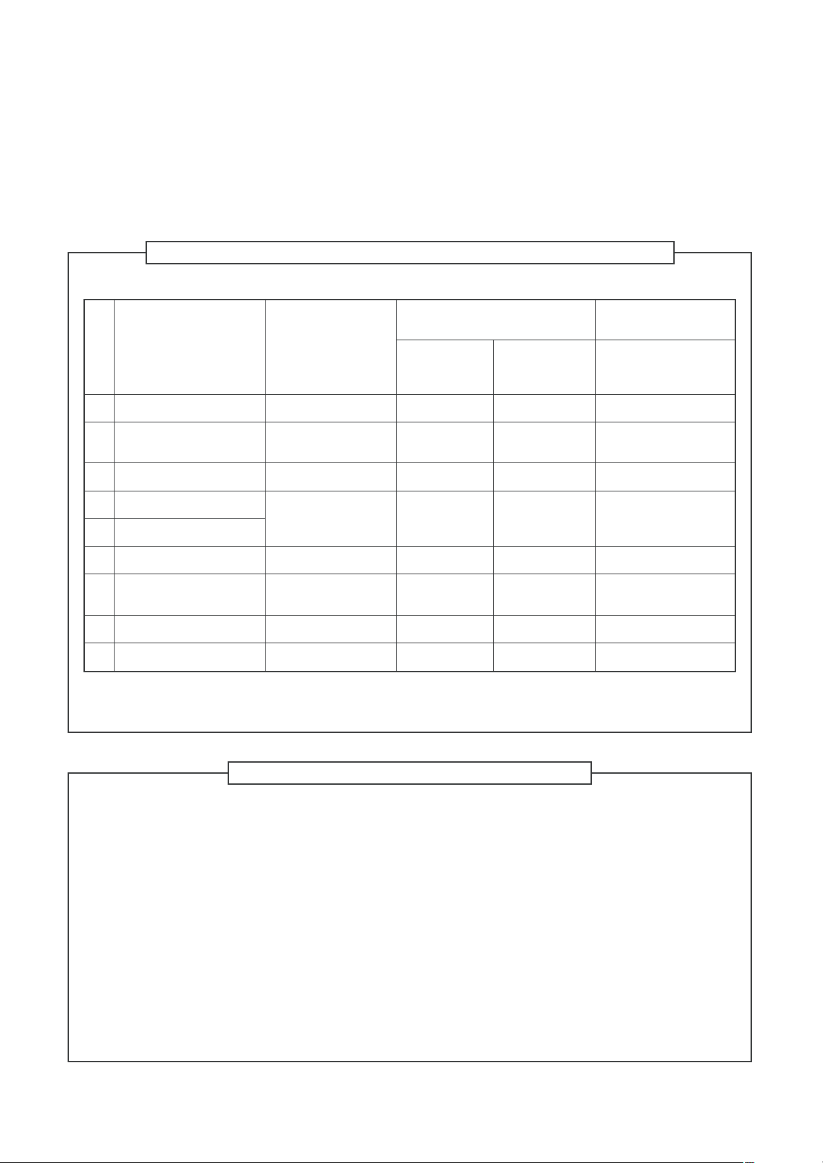
4. Tools
1. Required Tools for R410A
Mixing of different types of oil may cause a trouble such as generation of sludge, clogging of capillary, etc.
Accordingly, the tools to be used are classified into the following three types.
1) Tools exclusive for R410A (Those which cannot be used for conventional refrigerant (R22))
2) Tools exclusive for R410A, but can be also used for conventional refrigerant (R22)
3) Tools commonly used for R410A and for conventional refrigerant (R22)
The table below shows the tools exclusive for R410A and their interchangeability.
Tools exclusive for R410A (The following tools for R410A are required.)
Tools whose specifications are changed for R410A and their interchangeability
No.
Flare tool
Copper pipe gauge for
adjusting projection margin
Torque wrench
Gauge manifold
Charge hose
Vacuum pump adapter
Electronic balance for
refrigerant charging
Refrigerant cylinder
Leakage detector
Used tool
Usage
Pipe flaring
Flaring by conventional
flare tool
Tightening of flare nut
Evacuating, refrigerant
charge, run check, etc.
Vacuum evacuating
Refrigerant charge
Refrigerant charge
Gas leakage check
air conditioner installation
R410A
Existence of Whether conven-
new equipment tional equipment
for R410A can be used
Yes *(Note)
Yes *(Note)
Ye s N o
Ye s N o
Ye s N o
Ye s Ye s
Ye s N o
Ye s N o
Conventional air
conditioner installation
Whether conventional
equipment can be used
Ye s
*(Note)
No
No
Ye s
Ye s
No
Ye s
(Note) When flaring is carried out for R410A using the conventional flare tools, adjustment of projection
margin is necessary. For this adjustment, a copper pipe gauge, etc. are necessary.
General tools (Conventional tools can be used.)
In addition to the above exclusive tools, the following equipments which serve also for R22 are necessary
as the general tools.
1) Vacuum pump. Use vacuum pump by
attaching vacuum pump adapter. 7) Screwdriver (+, –)
2) Torque wrench 8) Spanner or Monkey wrench
3) Pipe cutter 9) Hole core drill
4) Reamer 10) Hexagon wrench (Opposite side 4mm)
5) Pipe bender 11) Tape measure
6) Level vial 12) Metal saw
Also prepare the following equipments for other installation method and run check.
1) Clamp meter 3) Insulation resistance tester (Megger)
2) Thermometer 4) Electroscope
– 7 –
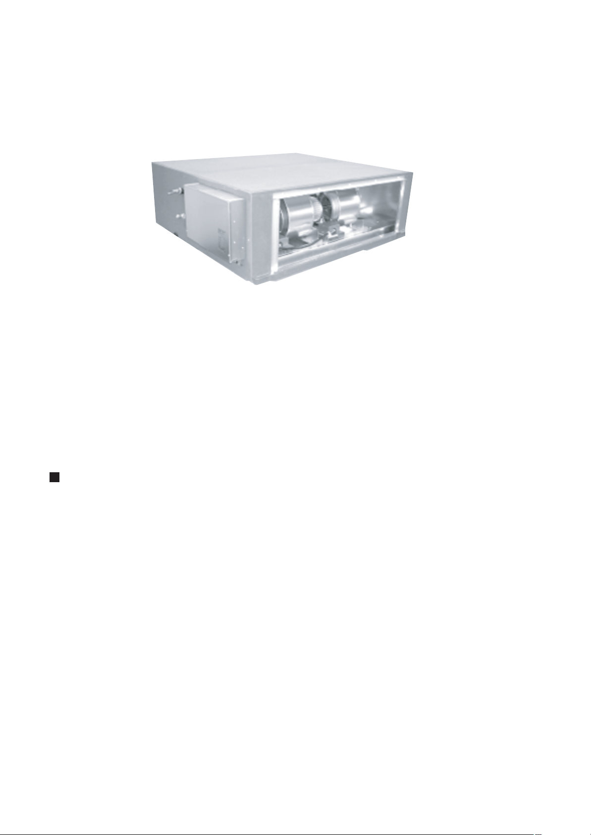
1. OUTLINE OF OUTSIDE AIR UNIT
• Type: Concealed Duct High Static Pressure type
Three models 4 ton, 6 ton and 8 ton are prepared.
• Connectable outdoor unit
SMMS-i series (MMY-MAP
UL, MMY-MAP
• Corresponding system
SMMS-i can connect to MMD-AP0481HF2UL for using diversity 30% (cooling basis) or below.
Definition
The Outside Air Unit means an air control for taken-in outside air.
Intake of the outside air often influences on the system so that the normal control of the air conditioner
becomes difficult or gives a large load upon air control and cooling performance.
Therefore it is frequently adopted to handle the outside air to a certain condition before the outside air will
enter in the main air conditioner.
This handling device is called a Outside Air Unit.
NOTE:
The Outside Air Unit is an air conditioner provided to handle the outside air load and is not to control the room
temperature.
For correspondence to the load of the indoor air control, set an air conditioner separately.
6HT9P-UL) of Heat pump super modular multi type outdoor unit.
∗∗∗
4HT6UL, MMY-MAP
∗∗∗
4HT9UL), SMMS-e series (MMY-MAP
∗∗∗
∗∗∗
6HT6P-
– 8 –
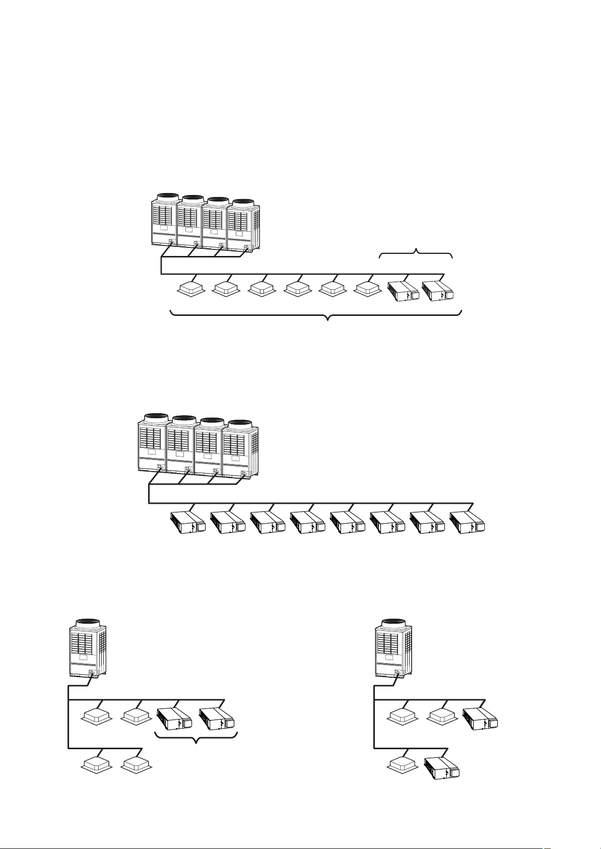
1-1. SMMS System Specifications to Connect Outside Air Unit
1-1-1. Combination conditions
• The Outside Air Unit is connectable to SMMS-i and SMMS-e.
• However this is not connectable to SHRM-i and SHRM-e.
• The total capacity of the indoor units and the Outside Air Units is restricted to 80% to 100% against the
capacity of the outdoor units. (This restriction should be strictly kept for correct control of the refrigerant.)
• Up to two Outside Air Units can be connected on one line of the multi system.
The allowable total capacity of the two Outside Air Units shall be 30% or less against the total capacity of the
indoor units (including the Outside Air Unit).
Up to two Outside Air Units
CORRECT
80 to 100% to capacity of the Outdoor Units
• The Outside Air Unit is usually used together with the indoor units on one line of the multi system.
The Outside Air Unit only cannot be connected.
occupy 30% or less against
total capacity of indoor units
INCORRECT
• Keep the height difference between the Outside Air Units to 19.7" (0.5m) or less.
Connection which stretches over two
floors is unavailable
CORRECT INCORRECT
Height difference:
19.7" (0.5m) or more
– 9 –
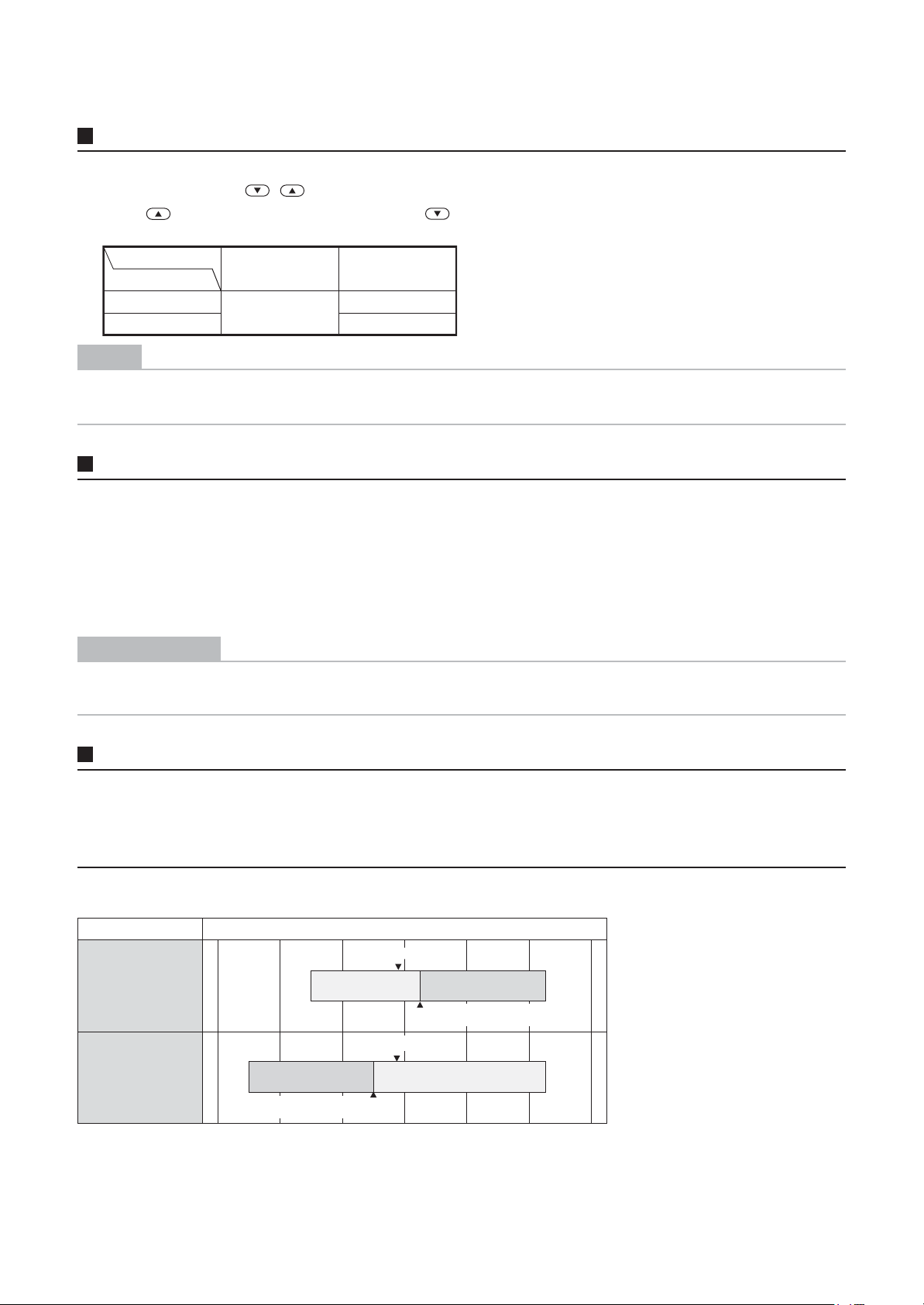
1-1-2. Use conditions
Changing the set temperature
1 Push the “TEMP. ” buttons of the wired remote control.
Push to increase the temperature, and to decrease the temperature. (The set temperature cannot
be changed in the fan mode.)
Operation mode
Setting range Factory default
COOL
HEAT 77 °F
61 to 80 °F
64 °F
NOTE
When heating
The air conditioner may continue running in the fan mode for about 30 seconds after stopping heating.
Operation mode and function
COOL : Cools the outside air and sends it into the room
HEAT : Heats the outside air and sends it into the room
FAN : Sends the outside air as it is
The air conditioner with the Outside Air Unit controls temperature of the supply air so that it is close to the
setup temperature of the remote control.
However temperature of the supply air may not be close to the setup temperature according to temperature of
the outside air or the operation condition of the indoor units for air conditioning in one line.
REQUIREMENT
• The air conditioner with the Outside Air Unit cannot control the room temperature.
• For control of the room temperature, an indoor unit for air conditioning is required separately.
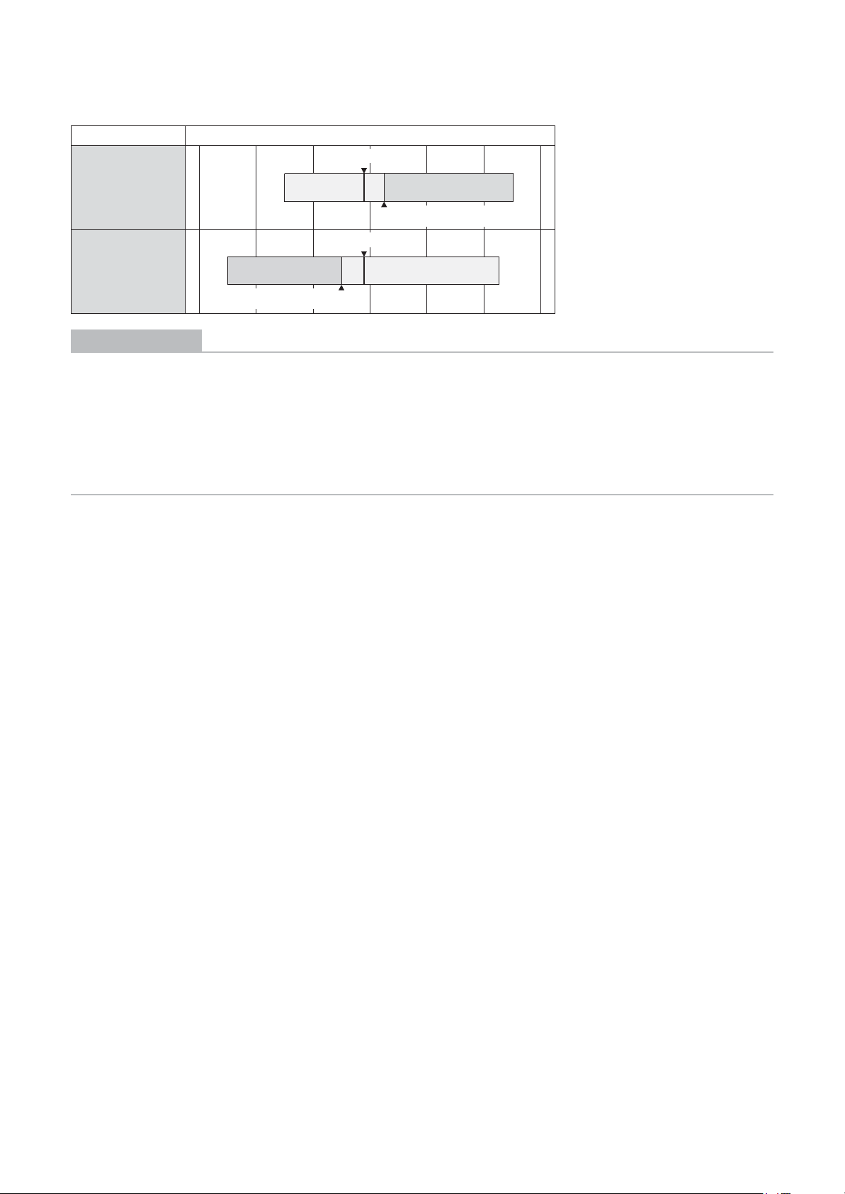
Use conditions
• In COOL mode, if temperature of the outside air is under the setup temp. +5.4 °F, FAN status is automatically made.
When temperature of the outside air is under 66 °F, FAN status is also made regardless of the setup temperature.
• In HEAT mode, if temperature of the outside air is over the setup temp. -5.4 °F, FAN status is automatically made.
When temperature of the outside air is over 59 °F, FAN status is also made regardless of the setup temperature.
• Case to use in SMMS-i
Outdoor Air Temperature °F
14 32 50 68 86 104 122
Setup temp.
Setup temp.
-5.4°F
+5.4°F
CoolingFan
Automatic COOL
operation starts
Fan
COOL mode
HEAT mode
41 109
23 109
Heating
Automatic HEAT
operation starts
– 10 –
• Case to use in SMMS-e
Outdoor Air Temperature °F
14 32 50 68 86 104 122
Setup temp.
Setup temp.
-5.4°F
+5.4°F
CoolingFan
Automatic COOL
operation starts
Fan
COOL mode
HEAT mode
41 115
23 109
Heating
Automatic HEAT
operation starts
REQUIREMENT
• In “COOL” or “FAN” mode, if temperature of the outside air is under 41 °F, the operation stop automatically in
order to protect the equipment.
In this case, continue the operation by selecting “HEAT” mode.
• In “HEAT” mode, if temperature of the outside air is under 23 °F, the operation stops automatically in order to
protect the equipment.
When operating the air conditioner with the outside air temp. under 23 °F (minimum 5 °F), set temp. of the
outside air to be taken in to 23 °F or upper using a duct heater (locally procured).
For details, consult the dealer which you purchased the air conditioner.
– 11 –
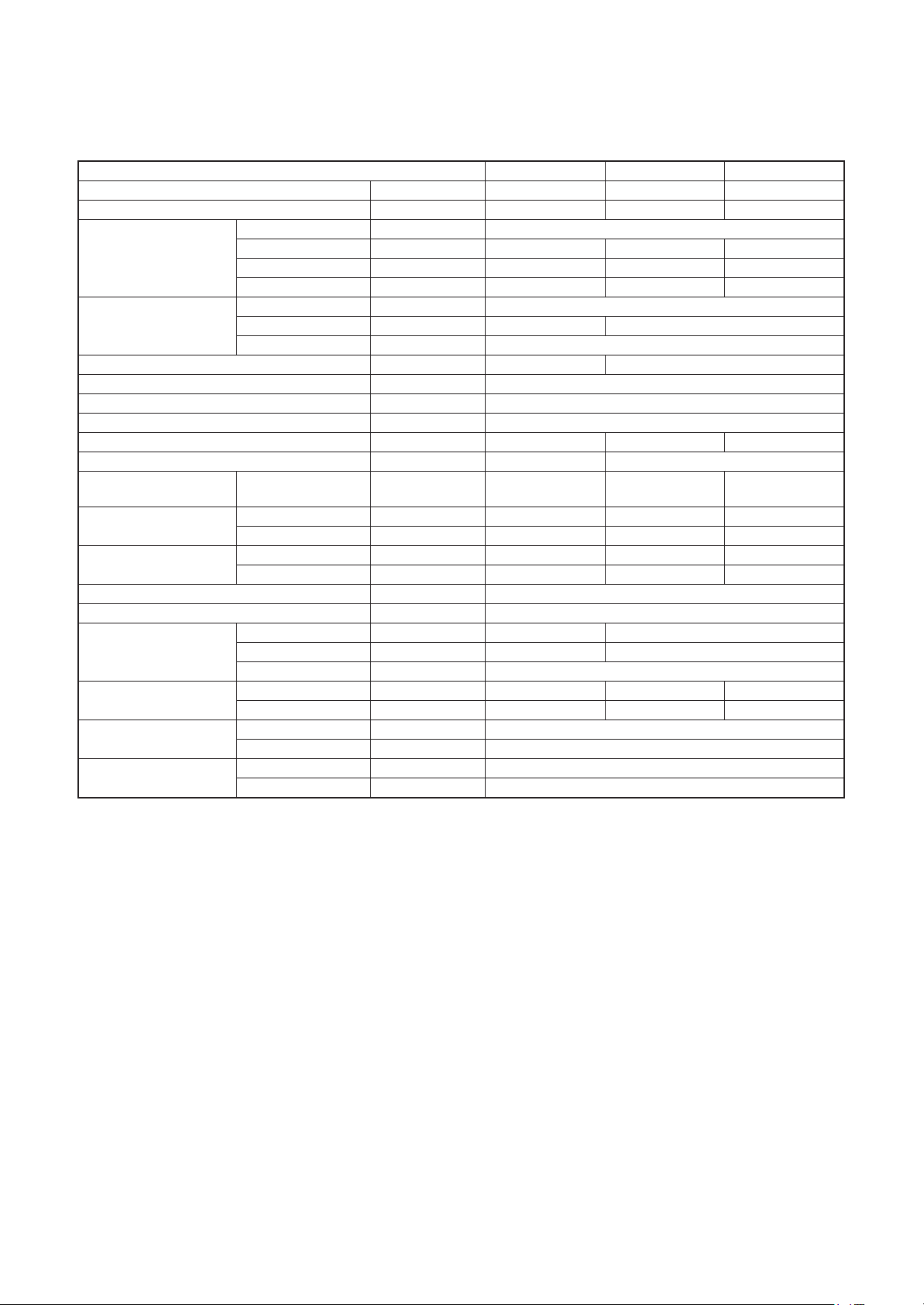
2. SPACIFICATIONS
Outside Air Unit
Model name MMD- AP0481HF2UL AP0721HF2UL AP0961HF2UL
Cooling capacity (Note1) kBtu/h 48.0 72.0 96.0
Heating capacity (Note1) kBtu/h 30.0 47.0 59.0
Power supply 230V (208/230V) 1phase
Electical
characteristics
Outer
dimension
Main unit weight lbs 212 349
Heat exchanger Finned tube
Soundproof / Heat-insulationg material Non-flammable insulation
Fan Centrifugal fan
Standard air flow cfm 636 989 1237
Motor W 160 160x2
External static pressure
(factory default)
Externalstatic
pressure
Air flow limit
Air filter Field supply
Control Wired remote control
Connecting
pipe
Sound pressure level
Operation
range for SMMS-i
Operation
range for SMMS-e
Running current A 1.58/1.56 3.00/2.88 3.32/3.17
Power consumption kW 0.31/0.34 0.56/0.58 0.64/0.66
Starting current A 3.90/3.20 7.70/6.30 8.50/6.90
Height In 19.5"
Width In 35.4" 55"
Depth In 49.8"
208V/230V In WG 0.55/0.86 0.74/1.00 0.41/0.85
208V(H / M / L) In WG 0.75/0.55/0.16 0.84/0.74/0.24 0.67/0.41
230V(H / M / L) In WG 1.06/0.86/0.50 1.08/1.00/0.65 1.01/0.85
Lower limit cfm 445 693 866
Upper limit cfm 700 1088 1360
Gas pipe In 5/8" 7/8"
Liquid pipe In 3/8" 1/2"
Drain pipe In
208V(H / M / L) dB(A) 44/43/36 47/46/40 47/45
230V(H / M / L) dB(A) 46/45/42 48/47/46 50/49
Cooling (Note 2) °F 41 - 109
Heating (Note 3) °F 23 - 109
Cooling (Note 2) °F 41 - 115
Heating (Note 3) °F 23 - 109
VP25
(Polyvinyl chloride tube : External Dia.1-1/4 internal Dia.1)
(H/L)
(H/L)
(H/L)
(H/L)
* The setting temperature is 60 - 80 °F.
* Height difference between Outside Air Units must be within 1.97"(0.5 m).
Note 1: Rated conditions Cooling : Outdoor air temperature 91 °F DB/82 °F WB setting temperature 64 °F
Heating : Outdoor air temperature 32 °F DB/26 °F WB setting temperature 77 °F
Note 2: * When supply air temperature is “setting temperature + 5.4 °F” or less, Outside Air Unit operates as
FAN mode.
Note 3: * When supply air temperature is “setting temperature - 5.4 °F” or over, Outside Air Unit operates as
FAN mode.
– 12 –
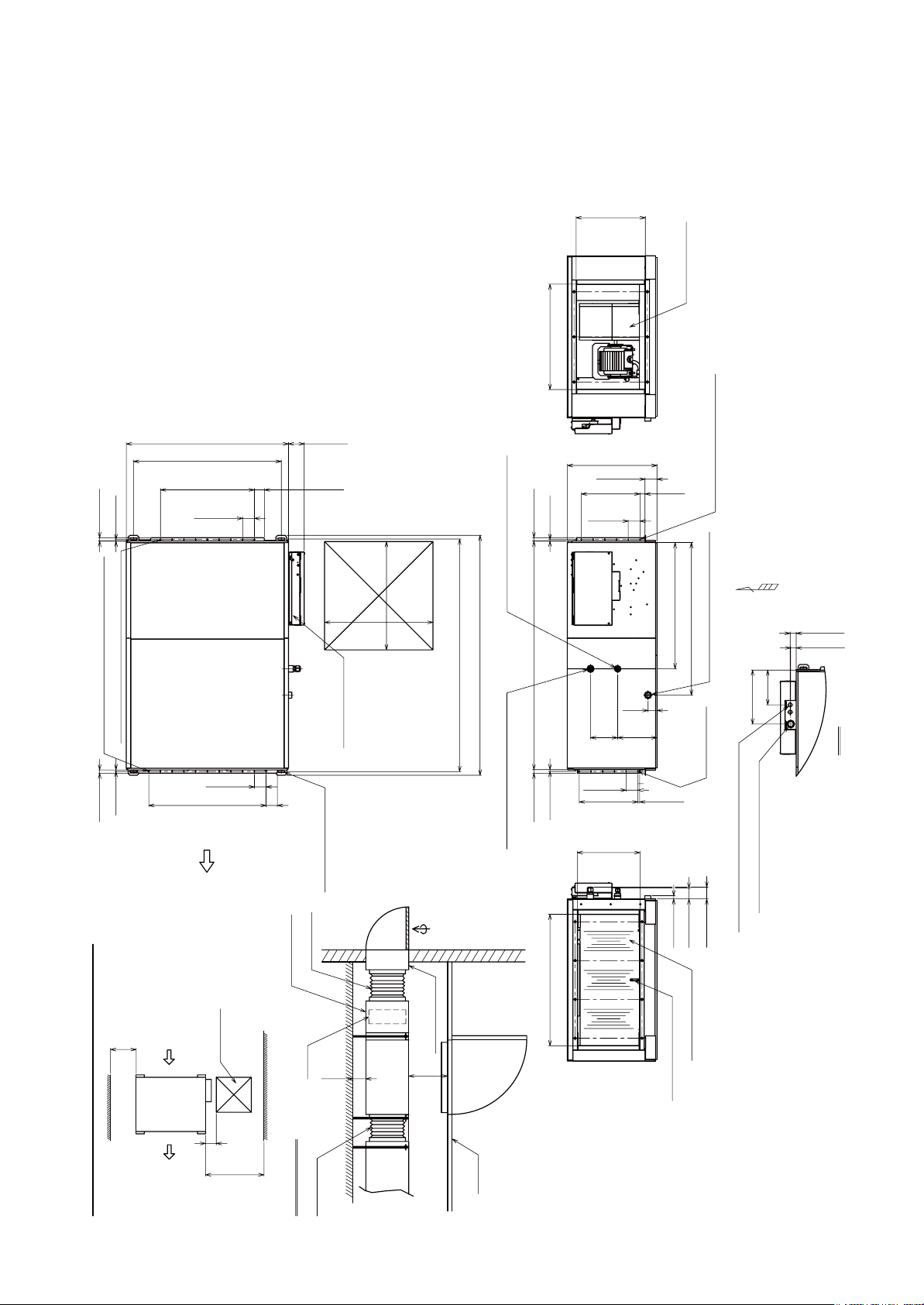
3. CONSTRUCTION VIEWS (EXTERNAL VIEWS)
3-1. MMD-AP0481HF2UL
1WVUKFG
1WVUKFG
Unit : in (mm)
#KTUWEVKQPRQTV
*CPIKPIDQNVOQWPVKPIRKVEJ
5ETGYJQNGHQTFWEVOQWPVKPI¹
5ETGYJQNGHQTFWEVOQWPVKPI¹
5GTXKEG
URCEG
1XGT
#KTHNQY
%JGEMRQTV
1WVUKFG
CKTWPKV
'NGEVTKERCTVUDQZ
*QNGHQTJCPIKPIDQNV
¹
%CPXCUFWEV
(KNVGTEJCODGT
1XGT
(KNVGT
1WVUKFG
CKTWPKV
4GHTKIGTCPVRKRGEQPPGEVKPIRQTV
%JGEMRQTV
*CPIKPIDQNVOQWPVKPIRKVEJ
1WVUKFGCKT
#KTKPVCMGFWEV
1XGT
%JGEMRQTV
.KSWKFUKFG¹(NCTGF
)CUUKFG¹(NCTGF
4GHTKIGTCPVRKRGEQPPGEVKPIRQTV
1WVUKFG
1WVUKFG
5ETGYJQNGHQTFWEVOQWPVKPI
¹
&TCKPRKRGEQPPGEVKPIRQTV8
5ETGYJQNGHQT
FWEVOQWPVKPI
¹
#KTFKUEJCTIGRQTV
&KUEJCTIGVGORUGPUQT
<
6CRGTUETGYHQT4RKRGU
<XKGY
CPFTGOQVGEQPVTQNYKTKPI
¹*QNGHQTEQPVTQNYKTG
¹*QNGHQTRQYGTUWRRN[ECDNG
5GTXKEG
1XGT
5RCEGTGSWKTGFHQTKPUVCNNCVKQPCPFUGTXKEKPI
URCEG
9QTMGZCORNG
%CPXCUFWEV
%GKNKPI
– 13 –
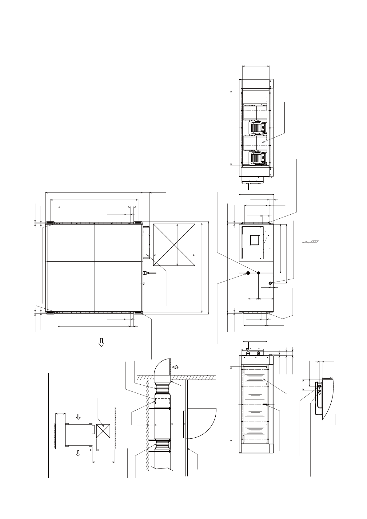
3-2. MMD-AP0721HF2UL, AP0961HF2UL
1WVUKFG
1WVUKFG
Unit : in (mm)
#KTUWEVKQPRQTV
*CPIKPIDQNVOQWPVKPIRKVEJ
5ETGYJQNGHQTFWEVOQWPVKPI¹
5ETGYJQNGHQTFWEVOQWPVKPI¹
#KTHNQY
'NGEVTKERCTVUDQZ
*QNGHQTJCPIKPIDQNV
¹
4GHTKIGTCPVRKRGEQPPGEVKPIRQTV
%JGEMRQTV
*CPIKPIDQNVOQWPVKPIRKVEJ
.KSWKFUKFG¹(NCTGF
)CUUKFG¹$TC\GF
4GHTKIGTCPVRKRGEQPPGEVKPIRQTV
1WVUKFG
5ETGYJQNGHQTFWEVOQWPVKPI
¹
<
&TCKPRKRGEQPPGEVKPIRQTV8
6CRGTUETGYHQT4RKRGU
5ETGYJQNGHQT
FWEVOQWPVKPI
¹
%CPXCUFWEV
(KNVGTEJCODGT
5GTXKEG
URCEG
1XGT
%JGEMRQTV
1WVUKFG
CKTWPKV
1XGT
5GTXKEG
URCEG
5RCEGTGSWKTGFHQTKPUVCNNCVKQPCPFUGTXKEKPI
1XGT
(KNVGT
9QTMGZCORNG
%CPXCUFWEV
1WVUKFG
CKTWPKV
1WVUKFGCKT
#KTKPVCMGFWEV
1XGT
– 14 –
%JGEMRQTV
%GKNKPI
1WVUKFG
#KTFKUEJCTIGRQTV
&KUEJCTIGVGORUGPUQT
CPFTGOQVGEQPVTQNYKTKPI
¹*QNGHQTEQPVTQNYKTG
¹*QNGHQTRQYGTUWRRN[ECDNG
<XKGY
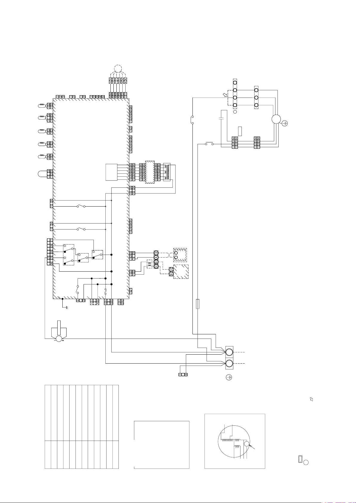
4. WIRING DIAGRAM
4-1. MMD-AP0481HF2UL
䎳䎰䎹
䎥䎯䎮
䎲䎵䎱
䎥䎯䎸
䎩䎤䎱䎔
䎪䎵䎼
䎵䎨䎧
䎺䎫䎬
2QYGTޓ5WRRN[
䎖
䎥䎯䎮
䎲䎵䎱
䎔䎕
䎥䎯䎸
䎗䎳
䎋䎺䎫䎬䎌
䎪䎵䎼
䎪䎵䎼
䎵䎨䎧
䎵䎨䎧
䎺䎫䎬
䎺䎫䎬
䎩䎰
䎪䎉䎼
䎵䎦
5ETGY
)TQWPF
䎩䎖 䎩䎗
䎩䎔 䎩䎕
䎤
䎗䎳
䎋䎺䎫䎬䎌
䎪䎵䎼
䎵䎨䎧
䎺䎫䎬
䎯䎕
䎯䎔
䎨䎻䎦䎷
䎳䎱䎯
䎷䎩
䎷䎦䎕 䎷䎦䎔
䎷䎦䎭
䎷䎤
䎵䎨䎧
䎯䎰
䎦䎱䎓䎖䎖
䯴䎪䎵䎱䎌
䯴䎥䎯䎸䎌
䎦䎱䎓䎙䎛
䎩䎤䎱
䎦䎱䎓䎛䎖䯴䎺䎫䎬䯵
䎦䎱䎓䎛䎓
䯴䎪䎵䎱䎌
䎦䎱䎔䎓䎖
䯴䎥䎵䎺䎌
䎦䎱䎔䎓䎓
䯴䎥䎯䎮䎌
䎦䎱䎔䎓䎔
䯴䎵䎨䎧䎌
䎦䎱䎔䎓䎕
䯴䎼䎨䎯䎌
䎦䎱䎔䎓䎗
䯴䎵䎨䎧䎌
䎦䎱䎓䎖䎓
䎸䎯䎯
䎫䎰
䎵䎼䎓䎓䎚
䎳䎖䎓䎔
䎥䎯䎮
䏖䏓䏄䏕䏎䎃䏎䏌䏏䏏䏈䏕
䎗䎖䎩䎔
䎩䎶
䎩䎬䎯䎷䎨䎵
䯴䎺䎫䎬䎌
䎦䎱䎓䎚䎓
䯴䎥䎯䎮䎌
䎦䎱䎓䎛䎔
䯴䎪䎵䎱䎌
䯴䎵䎨䎧䎌
䎦䎱䎓䎚䎖
䎰䎦䎦䎐䎔䎗䎓䎖
䏉䏒䏕䎃䎬䏑䏇䏒䏒䏕䎃䎸䏑䏌䏗
䎦䏒䏑䏗䏕䏒䏏䎃䎳䎑䎦䎑䎃䎥䏒䏄䏕䏇䎃
䎵䎼䎓䎓䎔
䎵䎼䎓䎓䎕
䎦䎱䎖䎓䎗䯴䎪䎵䎼䎌
䎦䎱䎖䎓䎜
䎵䎼䎓䎓䎘
䯴䎼䎨䎯䯵
䎤䎦䎬䎱
䎵䎨䎧
䎵䎼䎓䎓䎙
䎵䎼䎓䎓䎗
䎺䎫䎬
䏖䏘䏓䏓䏏䏜
䎳䏒䏚䏈䏕
䎩䏘䏖䏈
䎷䎘䎑䎓䎤䫹
䫹䫹䫹䫹䫹䎕䎘䎓䎹䱊
䎺䎫䎬
䯴䎥䎯䎸䎌
䎦䎱䎓䎛䎕
䎦䎱䎓䎙䎓䯴䎺䎫䎬䎌
䯴䎺䎫䎬䎌
䎦䎱䎓䎖䎕
䎦䎱䎓䎙䎔䯴䎼䎨䎯䎌
䯴䎺䎫䎬䎌
䎦䎱䎓䎚䎘
䏆䏌䏕䏆䏘䏌䏗
䎦䎱䎓䎚䎗䯴䎺䎫䎬䎌
䎦䎱䎓䎘䎓䯴䎺䎫䎬䎌
䎦䎱䎓䎗䎔䯴䎥䎯䎸䎌
䎦䎱䎓䎗䎓
䯴䎥䎯䎸䎌
䎦䎱䎓䎗䎗䯴䎥䎵䎺䎌
䎦䎱䎓䎙䎙䯴䎺䎫䎬䎌
䎦䎱䎓䎙䎚䯴䎥䎯䎮䎌
䎩䎤䎱 䎲䎳䎷䎬䎲䎱
䎧䎵䎬䎹䎨
䎷䎔䎓
䎵䎦
䎲䎦
䎨䎰䎪
䎦䎱䎓䎕
䯴䎼䎨䎯䎌
䎥䎯䎮
䎥䎯䎮
䎥䎯䎸
䎥䎯䎸
䎦䎱䎓䎔
䯴䎺䎫䎬䎌
䎰䎦䎦䎐䎔䎘䎕䎓
䎶䏘䏅䎃䎳䎑䎦䎑䎥䏒䏄䏕䏇
䎯䏌䏑䏈䎃䎩䏌䏏䏗䏈䏕
䎺䎫䎬
䎵䎨䎧
䎷䎵䎔
䎵䏈䏐䏒䏗䏈
䎤䎥
䎵䏈䏐䏒䏗䏈
䎲䏘䏗䏇䏒䏒䏕
䎵䎨䎧
䎦䏒䏑䏗䏕䏒䏏䏏䏈䏕
䎥䏒䏄䏕䏇
䎦䏒䏑䏗䏕䏒䏏䏏䏈䏕
䎸䏑䏌䏗
䎺䎫䎬
%QPPGEVQT
䎗䎖䎩䎔
䎗䎙
䎺䎫䎬
䎵䎨䎧
䎩䎔
䎵䎨䎧
䎗䎖䎩䎔
䎘
䎷䎔䎓䎤䎏䎕䎘䎓䎹䱊
7PKV
+PFQQT
䎖
䎩䏄䏑䎃䎰䏒䏗䏈䏕
䎳䏄䏕䏗䏖䫹䎱䏄䏐䏈
䎵䏘䏑䏑䏌䏑䏊䎃䎦䏄䏓䏄䏆䏌䏗䏒䏕
䎵䎦
䎩䎰
䎶䏜䏐䏅䏒䏏
䎷䏕䏄䏑䏖䏉䏒䏕䏐䏈䏕
䎷䎵䎔
䎷䏈䏐䏓䎃䏖䏈䏑䏖䏒䏕
䎥䏏䏒䏚䎃䏗䏈䏐䏓䎑䎃䏖䏈䏑䏖䏒䏕
䎬䏑䏗䏄䏎䏈䎃䏄䏌䏕䎃䏗䏈䏐䏓䎑䎃䏖䏈䏑䏖䏒䏕
䎷䎤
䎩䏄䏑䎃䎰䏒䏗䏒䏕䎃䎦䏒䏑䏗䏕䏒䏏䎃䎵䏈䏏䏄䏜
䎷䎩
䎵䎼䎓䎓䎘䱊䎓䎓䎚
䎷䎦䎔䎏䎷䎦䎕䎏䎷䎦䎭
䎳䏘䏏䏖䏈䎃䎰䏒䏗䏒䏕䎃䎹䏄䏏䏙䏈
䎩䏘䏖䏈䎃䏉䏒䏕䎃䎩䏄䏑䎃䎰䏒䏗䏒䏕
䎧䏕䏄䏌䏑䎃䎦䏒䏑䏗䏕䏒䏏䎃䎵䏈䏏䏄䏜
䎵䎼䎓䎓䎕
䎩䏄䏑䎃䎰䏒䏗䏒䏕䎃䎦䏒䏑䏗䏕䏒䏏䎃䎵䏈䏏䏄䏜
䎩䎔
䎳䎰䎹
䎗䎖䎩䎔
䰏䰛䰘䰛䰞
䰕䰐䰑䰚䰠䰕䰒䰕䰏䰍䰠䰕䰛䰚
䰞䰑䰐䰆䰞䰑䰐
䰥䰑䰘䰆䰥䰑䰘䰘䰛䰣
䰣䰔䰕䰆䰣䰔䰕䰠䰑
䰎䰘䰗䰆䰎䰘䰍䰏䰗
䰎䰘䰡䰆䰎䰘䰡䰑
䰓䰞䰥䰆䰓䰞䰍䰥
䰜䰚䰗䰆䰜䰕䰚䰗
䰛䰞䰚䰆䰛䰞䰍䰚䰓䰑
䰎䰞䰣䰆䰎䰞䰛䰣䰚
䰓䯳䰥䰆䰓䰞䰑䰑䰚䯳䰥䰑䰘䰘䰛䰣
– 15 –
140
$.7
YKTKPIFKCITCO
(CPOQVQTKPUKFG
$.-
(
/QVQTQXGTJGCVKPI
9*+
4'&
)4;
RTQVGEVKQPUYKVEJ
䎃䎃䎯䏈䏗䏗䏈䏕䎃䏄䏗䎃䏌䏑䏖䏌䏇䏈䎃䏌䏑䏇䏌䏆䏄䏗䏈䏖䎃䏗䏋䏈䎃䏗䏈䏕䏐䏌䏑䏄䏏䎃䏑䏘䏐䏅䏈䏕䎑䫹
䎔䎑䧍䎃䏌䏑䏇䏌䏆䏄䏗䏈䏖䎃䏗䏋䏈䎃䏗䏈䏕䏐䏌䏑䏄䏏䎃䏅䏏䏒䏆䏎䎑
䎃䎃䏑䏘䏐䏅䏈䏕䎃䏄䏖䎃䏉䏌䏊䏘䏕䏈䎃䏄䏑䏇䎃䏏䏈䏄䏇䎃䏚䏌䏕䏈䎊䏖䎃䏆䏒䏏䏒䏕䎃䏒䏉䎃䏉䏄䏑䎃䏐䏒䏗䏒䏕䎑
䎃䎃䏈䏛䏆䏋䏄䏑䏊䏈䎃䏗䏋䏈䎃䏏䏈䏄䏇䎃䏚䏌䏕䏈䎃䏒䏉䎃䏄䏕䏕䏒䏚䎃䎋䎃䎃䎃䎌䎃䏓䏒䏖䏌䏗䏌䏒䏑䎃䏄䏉䏗䏈䏕䎃䏆䏋䏈䏆䏎䎃䏗䏋䏈䎃䏗䏈䏕䏐䏌䏑䏄䏏䎃
䎗䎑䎃䎤䎃䎃䏓䏒䏖䏌䏗䏌䏒䏑䎃䏌䏖䎃䏆䏒䏑䏑䏈䏆䏗䏈䏇䎃䏗䏒䎃䏗䏈䏕䏐䏌䏑䏄䏏䎃䏅䏏䏒䏆䏎䎃䏚䏋䏈䏑䎃䏆䏋䏄䏑䏊䏈䎃䏗䏒䎃䏖䏗䏄䏗䏌䏆䎃䏓䏕䏈䏖䏖䏘䏕䏈䎑
䎖䎑䎃䎃䎃䎃䎃䎃䎃䎃䏌䏑䏇䏌䏆䏄䏗䏈䏖䎃䏗䏋䏈䎃䏆䏒䏑䏗䏕䏒䏏䎃䎳䎑䎦䎃䏅䏒䏄䏕䏇䎑
䎕䎑䎤䎃䏇䏒䏗䏗䏈䏇䎃䏏䏌䏑䏈䎃䏄䏑䏇䎃䏅䏕䏒䏎䏈䏑䎃䏏䏌䏑䏈䎃䏌䏑䏇䏌䏆䏄䏗䏈䎃䏗䏋䏈䎃䏚䏌䏕䏌䏑䏊䎃䏄䏗䎃䏖䏌䏗䏈䎑
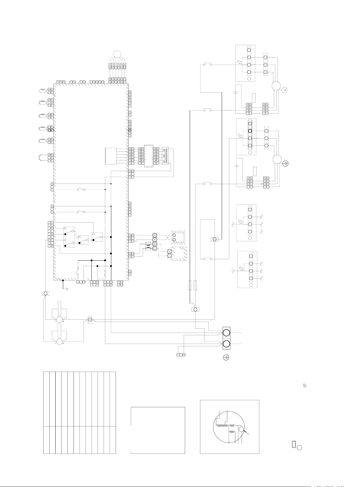
4-2. MMD-AP0721HF2UL, AP0961HF2UL
2/8
':%6
20.
6(
6%
6%
6%,
6#
4'&
4'&
./
%0
㧔)40
%0
㧔$.7
(#0
%0㧔9*+㧕
4'&
%0
㧔)40
%0
㧔$49
%0
㧔$.-
%0
㧔4'&
%0
㧔;'.
%0
㧔4'&
7..
/*
4;
2
$.-
䏖䏓䏄䏕䏎䎃䏎䏌䏏䏏䏈䏕
(
䏖䏓䏄䏕䏎䎃䏎䏌䏏䏏䏈䏕
(
%0
(5
(+.6'4
㧔9*+
%0
%0
㧔)40
%0
㧔4'&
㧔$.-
/%%
HQT+PFQQT7PKV
UWRRN[
2QYGT
%QPVTQN2%$QCTF
4;
4;
%0㧔)4;
%0
4;
㧔;'.㧕
(WUG
6㧚#ޓ8㨪
#%+04'&
9*+
4;
4;
9*+
9*+
%0
㧔$.7
%0㧔9*+
%0
㧔9*+
%0㧔;'.
%0
㧔9*+
EKTEWKV
%0㧔9*+
%0㧔9*+%0㧔$.7
%0
㧔$.7
%0㧔$49
%0㧔9*+
%0㧔$.-
126+10
(#0
6
4%
1%
'/)
&4+8'
%0
㧔;'.
䎶䏘䏅䎃䎳䎑䎦䎑䎥䏒䏄䏕䏇
$.-
$.-
$.7
$.7
䎯䏌䏑䏈䎃䎩䏌䏏䏗䏈䏕
%0
㧔9*+
䎰䎦䎦䎐䎔䎘䎕䎓
64
4'&
4'&
4GOQVG
%QPVTQNNGT
䎥䏒䏄䏕䏇
䎤䎥
䎵䏈䏐䏒䏗䏈
䎦䏒䏑䏗䏕䏒䏏䏏䏈䏕
7PKV
1WVFQQT
(
(
4'&
4'&
4'&
9*+
4'&
4'&
9*+
%QPPGEVQT
140
䎘
䎘
䎘
䎘
9*+
(
(
䎗
(
䎗
(
䎖 䎖
9*+
7PKV
+PFQQT
5ETGY
)TQWPF
(((
V[RG
䎵䎦䎔
2
)4;
4'&
9*+
V[RG
䎵䎦䎕
)4;
4'&
9*+
V[RG
V[RG
(
2
䎤
9*+
(
(
(
(
䎤
$.7
(((
(
䎤
(
((
(
䎤
$.-
$.-
140
140
$.7
$.7
(/
);
2
(#0
9*+
)4;
)4;
)4;
4'&
4'&
4'&
9*+
9*+
9*+
$.-
$.-
140
140
$.7
$.7
(/
);
2
(#0
9*+
)4;
)4;
)4;
4'&
4'&
4'&
9*+
9*+
9*+
$.-
140
$.7
$.-
140
$.7
.
.
2QYGTޓ5WRRN[
䎩䏄䏑䎃䎰䏒䏗䏈䏕
䎳䏄䏕䏗䏖䫹䎱䏄䏐䏈
䎵䏘䏑䏑䏌䏑䏊䎃䎦䏄䏓䏄䏆䏌䏗䏒䏕
䎵䎦
䎩䎰
䎶䏜䏐䏅䏒䏏
䎷䏕䏄䏑䏖䏉䏒䏕䏐䏈䏕
䎷䎵䎔
䎷䏈䏐䏓䎃䏖䏈䏑䏖䏒䏕
䎥䏏䏒䏚䎃䏗䏈䏐䏓䎑䎃䏖䏈䏑䏖䏒䏕
䎬䏑䏗䏄䏎䏈䎃䏄䏌䏕䎃䏗䏈䏐䏓䎑䎃䏖䏈䏑䏖䏒䏕
䎷䎤
䎩䏄䏑䎃䎰䏒䏗䏒䏕䎃䎦䏒䏑䏗䏕䏒䏏䎃䎵䏈䏏䏄䏜
䎷䎩
䎵䎼䎓䎓䎘䱊䎓䎓䎚
䎷䎦䎔䎏䎷䎦䎕䎏䎷䎦䎭
䎳䏘䏏䏖䏈䎃䎰䏒䏗䏒䏕䎃䎹䏄䏏䏙䏈
䎩䏘䏖䏈䎃䏉䏒䏕䎃䎩䏄䏑䎃䎰䏒䏗䏒䏕
䎧䏕䏄䏌䏑䎃䎦䏒䏑䏗䏕䏒䏏䎃䎵䏈䏏䏄䏜
䎵䎼䎓䎓䎕
䎩䏄䏑䎃䎰䏒䏗䏒䏕䎃䎦䏒䏑䏗䏕䏒䏏䎃䎵䏈䏏䏄䏜
䎩䎔
䎳䎰䎹
䎗䎖䎩䎔
䰏䰛䰘䰛䰞
䰕䰐䰑䰚䰠䰕䰒䰕䰏䰍䰠䰕䰛䰚
䰞䰑䰐䰆䰞䰑䰐
䰥䰑䰘䰆䰥䰑䰘䰘䰛䰣
䰣䰔䰕䰆䰣䰔䰕䰠䰑
䰎䰘䰗䰆䰎䰘䰍䰏䰗
䰎䰘䰡䰆䰎䰘䰡䰑
䰓䰞䰥䰆䰓䰞䰍䰥
䰜䰚䰗䰆䰜䰕䰚䰗
䰛䰞䰚䰆䰛䰞䰍䰚䰓䰑
䰎䰞䰣䰆䰎䰞䰛䰣䰚
䰓䯳䰥䰆䰓䰞䰑䰑䰚䯳䰥䰑䰘䰘䰛䰣
– 16 –
140
$.7
YKTKPIFKCITCO
(CPOQVQTKPUKFG
$.-
(
/QVQTQXGTJGCVKPI
9*+
4'&
)4;
RTQVGEVKQPUYKVEJ
䎃䎃䎯䏈䏗䏗䏈䏕䎃䏄䏗䎃䏌䏑䏖䏌䏇䏈䎃䏌䏑䏇䏌䏆䏄䏗䏈䏖䎃䏗䏋䏈䎃䏗䏈䏕䏐䏌䏑䏄䏏䎃䏑䏘䏐䏅䏈䏕䎑䫹
䎔䎑䧍䎃䏌䏑䏇䏌䏆䏄䏗䏈䏖䎃䏗䏋䏈䎃䏗䏈䏕䏐䏌䏑䏄䏏䎃䏅䏏䏒䏆䏎䎑
䎃䎃䏑䏘䏐䏅䏈䏕䎃䏄䏖䎃䏉䏌䏊䏘䏕䏈䎃䏄䏑䏇䎃䏏䏈䏄䏇䎃䏚䏌䏕䏈䎊䏖䎃䏆䏒䏏䏒䏕䎃䏒䏉䎃䏉䏄䏑䎃䏐䏒䏗䏒䏕䎑
䎃䎃䏈䏛䏆䏋䏄䏑䏊䏈䎃䏗䏋䏈䎃䏏䏈䏄䏇䎃䏚䏌䏕䏈䎃䏒䏉䎃䏄䏕䏕䏒䏚䎃䎋䎃䎃䎃䎌䎃䏓䏒䏖䏌䏗䏌䏒䏑䎃䏄䏉䏗䏈䏕䎃䏆䏋䏈䏆䏎䎃䏗䏋䏈䎃䏗䏈䏕䏐䏌䏑䏄䏏䎃
䎗䎑䎃䎤䎃䎃䏓䏒䏖䏌䏗䏌䏒䏑䎃䏌䏖䎃䏆䏒䏑䏑䏈䏆䏗䏈䏇䎃䏗䏒䎃䏗䏈䏕䏐䏌䏑䏄䏏䎃䏅䏏䏒䏆䏎䎃䏚䏋䏈䏑䎃䏆䏋䏄䏑䏊䏈䎃䏗䏒䎃䏖䏗䏄䏗䏌䏆䎃䏓䏕䏈䏖䏖䏘䏕䏈䎑
䎖䎑䎃䎃䎃䎃䎃䎃䎃䎃䏌䏑䏇䏌䏆䏄䏗䏈䏖䎃䏗䏋䏈䎃䏆䏒䏑䏗䏕䏒䏏䎃䎳䎑䎦䎃䏅䏒䏄䏕䏇䎑
䎕䎑䎤䎃䏇䏒䏗䏗䏈䏇䎃䏏䏌䏑䏈䎃䏄䏑䏇䎃䏅䏕䏒䏎䏈䏑䎃䏏䏌䏑䏈䎃䏌䏑䏇䏌䏆䏄䏗䏈䎃䏗䏋䏈䎃䏚䏌䏕䏌䏑䏊䎃䏄䏗䎃䏖䏌䏗䏈䎑
5. PARTS RATING
Parts name MMD-AP0481HF2UL
Fan motor STF200-160U4A
Running capacitor for fan motor 400V 6µF 400V 4µF
Transformer TT-12
TA sensor Lead wire length: 47.2 in (1200mm) Lead wire length: 32.2 in (818mm)
TF sensor Lead wire length: 98.4 in (2500mm)
TC1 sensor
TC2 sensor
TCJ sensor
Pulse motor EDM-MD12TF-3
Electronic control valve EDM-B60YGTF-1 EDM-BAOYGTF-1
Ø0.16 in (Ø4 mm) size, Lead wire length:
47.2 in (1200mm), Vinyl tube (Blue)
Ø0.24 in (Ø6 mm) size, Lead wire length:
47.2 in (1200mm), Vinyl tube (Black)
Ø0.24 in (Ø6 mm) size, Lead wire length:
47.2 in (1200mm), Vinyl tube (Red)
MMD-AP0721HF2UL, MMD-AP0961HF2UL
Ø0.16 in (Ø4 mm) size, Lead wire length:
78.7 in (2000mm), Vinyl tube (Blue)
Ø0.24 in (Ø6 mm) size, Lead wire length:
78.7 in (2000mm), Vinyl tube (Black)
Ø0.24 in (Ø6 mm) size, Lead wire length:
78.7 in (2000mm), Vinyl tube (Red)
– 17 –

6. FAN CHARACTERISTIC
䇭
䇭
䇭
䇭
<MMD-AP0481HF2UL>
Tap
ddiM
230V䇭
230V
636
tar wolf ria dradnatSerusserp citats lanretxE
Tap
V032A - mfc
cfm - A
V032scitsiretcarahc naF
Fan characteristics
zH 06 / V 802 :ecruos rewoPzH 06 / V 032 :ecruos rewoP
57.0hgiH60.1hgiH
55.0elddiM68.0el
61.0woL05.0woL
636
etar wolf ria dradnatSerusserp citats lanretxEe
)mfc()GW ni()mfc()GW ni(
– 18 –
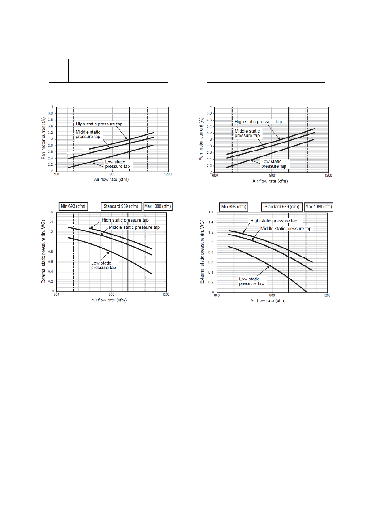
<MMD-AP0721HF2UL>
䇭
V
䇭
V
䇭
V
䇭
230V䇭
230
atetar wolf ria dradnatSerusserp citats lanretxEpat
00.1elddiM
989 989
032A - mfc
cfm - A
032scitsiretcarahc naF
Fan characteristics
zH 06 / V 802 :ecruos rewoPzH 06 / V 032 :ecruos rewoP
48.0hgiH80.1hgiH
47.0elddiM
42.0woL56.0woL
etar wolf ria dradnatSerusserp citats lanretxEp
)mfc()GW ni()mfc()GW ni(
– 19 –
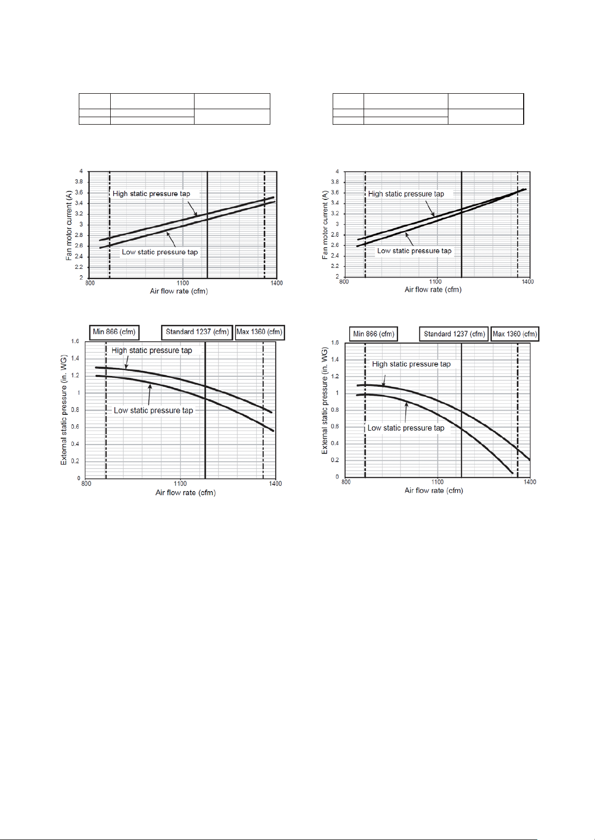
<MMD-AP0961HF2UL>
䇭
V
䇭
V
䇭
V
䇭
230V䇭
230
atetar wolf ria dradnatSerusserp citats lanretxEpat
0woL
1237 1237
032A - mfc
cfm - A
032scitsiretcarahc naF
Fan characteristics
zH 06 / V 802 :ecruos rewoPzH 06 / V 032 :ecruos rewoP
76.0hgiH10.1hgiH
14.0woL58.
etar wolf ria dradnatSerusserp citats lanretxEp
)mfc()GW ni()mfc()GW ni(
– 20 –

Wire connection change of fan motor
F
The motor wires for the fan have been connected to
Change the wire connection if change of the external static pressure is required due to the duct resistance.
<MMD-AP048 type>
FM
Fan motor
Black
Blue
Orange
F1 F2 F3 F4
Control
2
at shipment from the factory.
Electrical control box
P.C.
board
Orange (at shipment of factory)
4P terminal block
Lead wire for changing the external static pressure
When changing the external static pressure is
necessary, change connection of this lead wire.
2P terminal block
<MMD-AP072 type, AP096 type>
Electrical control box
FM
Fan motor
Blue
F1 F2 F3 F4 F1 F2 F3 F4
Orange (at shipment of factory)
Black
Orange
FM
Fan motor
Blue
Orange (at shipment of factory)
Control
P.C.
Black
Orange
2P terminal block
Lead wire for changing the external static pressure
When changing the external static pressure is
necessary, change connection of this lead wire.
board
4P terminal block
REQUIREMENT
When the external static pressure was changed, enter the changed static pressure value in the identification
plate of the unit.
<MMD-AP048, AP072 type>
Terminal block No. Fan motor wiring Remarks
F1 (Low static pressure tap) Blue —
F2 (Middle static pressure tap) Orange At shipment from factory
F3 (High static pressure tap) Black —
<MMD-AP096 type>
Terminal block No. Fan motor wiring Remarks
F1 (-) Blue Not used.
F2 (Low static pressure tap) Orange At shipment from factory
F3 (High static pressure tap) Black —
– 21 –
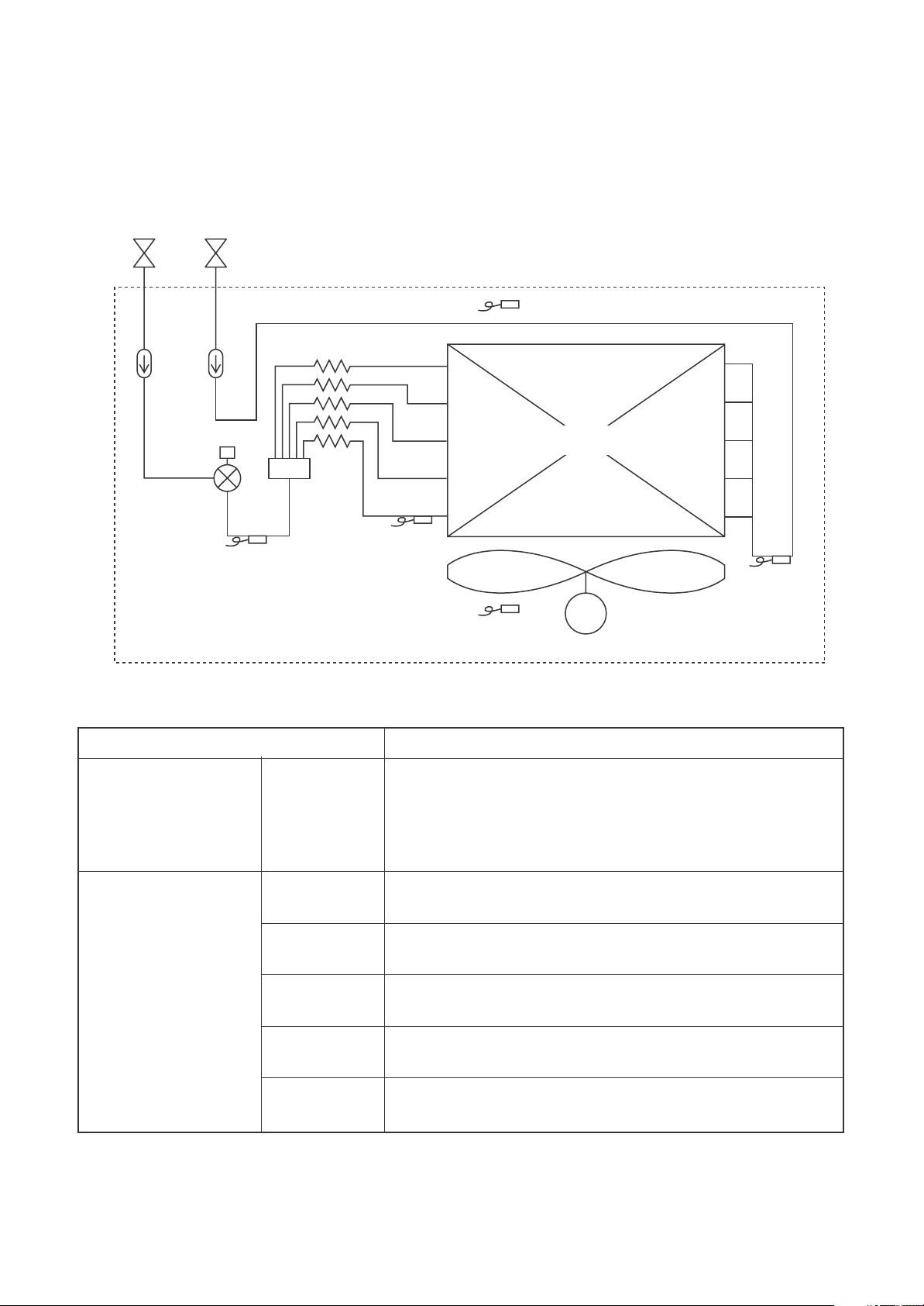
7. REFRIGERATING CYCLE DIAGRAM
Gas sideLiquid side
Sensor (TF)
Strainer
Pulse Motor
Valve (PMV)
Sensor
(TC2)
Capillary tube
Functional part name
Pulse motor valve PMV
Air heat exchanger
at indoor side
Sensor
(TCJ)
Sensor
(TA)
Fan
M
Fan motor
Function outline
(Connector CN082 (6P): Blue)
1) Super heat control function in cooling operation
2) Subcool control function in heating operation
3) Cooling refrigerant oil recovery function
4) Heating refrigerant oil recovery function
Sensor
(TC1)
1. TA
2. TC1
Temperature sensor 3. TC2
4. TCJ
5. TF
(Connector CN104 (2P): Yellow)
1) For detection of outdoor suction temperature
(Connector CN100 (3P): Brown)
1) For super heat control of PMV in cooling operation
(Connector CN101 (2P): Black)
1) For subcool control of PMV in heating operation
(Connector CN102 (2P): Red)
1) For super heat control of PMV in cooling operation
(Connector CN103 (2P): Green)
1) For detection of discharge temperature
– 22 –
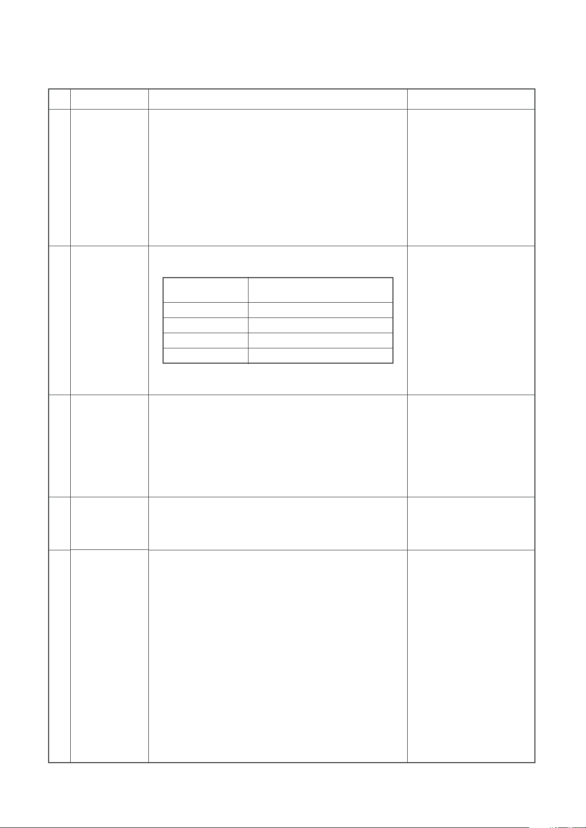
8. CONTROL OUTLINE
No.
1
When power
supply is reset
2
Operation
selection
Item
Outline of specifications
1) Distinction of outdoor units
When the power supply is reset, the outdoor units are
distinguished, and control is selected according to the
distinguished result.
2) If resetting the power during a problem, the check
code is cleared. After ON/OFF button on the remote
control is pushed to resume operation and the
problem persists, the check code is again displayed
on the remote control.
1) The operation mode is selected based on the
operation mode command on the remote control.
Command from
remote control
STOP
FAN
COOL
HEAT
* DRY or AUTO mode cannot be selected.
Outside Air Unit stops.
Fan operation
Cooling operation
Heating operation
Control outline
Remarks
Remote
3
control setup
temperature
Capacity
4
control
PMV control
5
1) Adjustment range
Adjustment range
• In cooling or heating operation: 61 to 81 ˚F
[ 16 to 27 ˚C ]
At shipment from factory:
• In cooling operation: 64 ˚F [ 18 ˚C ]
• In heating operation: 77 ˚F [ 25 ˚C ]
1) Differed from other indoor air conditioners, the
Outside Air Unit usually operates with the maximum
capacity.
1) Outside Air Unit controls PMV using the corrected
value of each sensor according to the operation mode.
COOL
• SH control is performed by correcting indoor coil
temp (TC1) and inlet air temp. from outside (TA).
HEAT
• UC control is performed by correcting indoor coil
temp (TC2, TCJ) and inlet air temp. from outside
(TA).
2) The value displayed by monitor function of the remote
control switch becomes the corrected sensor data.
(See Monitor function of the remote control switch.)
Data to be corrected:
Inlet air temp. from outside
(TA), Indoor coil temp
(TCJ, TC2, TC1)
– 23 –
No.
23 ˚F [ –5 ˚C]
TS –5.4 ˚F [–3 ˚C]
41 ˚F [5 ˚C]
TS +5.4 ˚F [3 ˚C] 109 ˚F [43 ˚C]
23 ˚F [ –5 ˚C]
TS –5.4 ˚F [ –3 ˚C] 109 ˚F [43 ˚C]
41 ˚F [5 ˚C]
TS +5.4 ˚F [3 ˚C] 115 ˚F [46 ˚C]
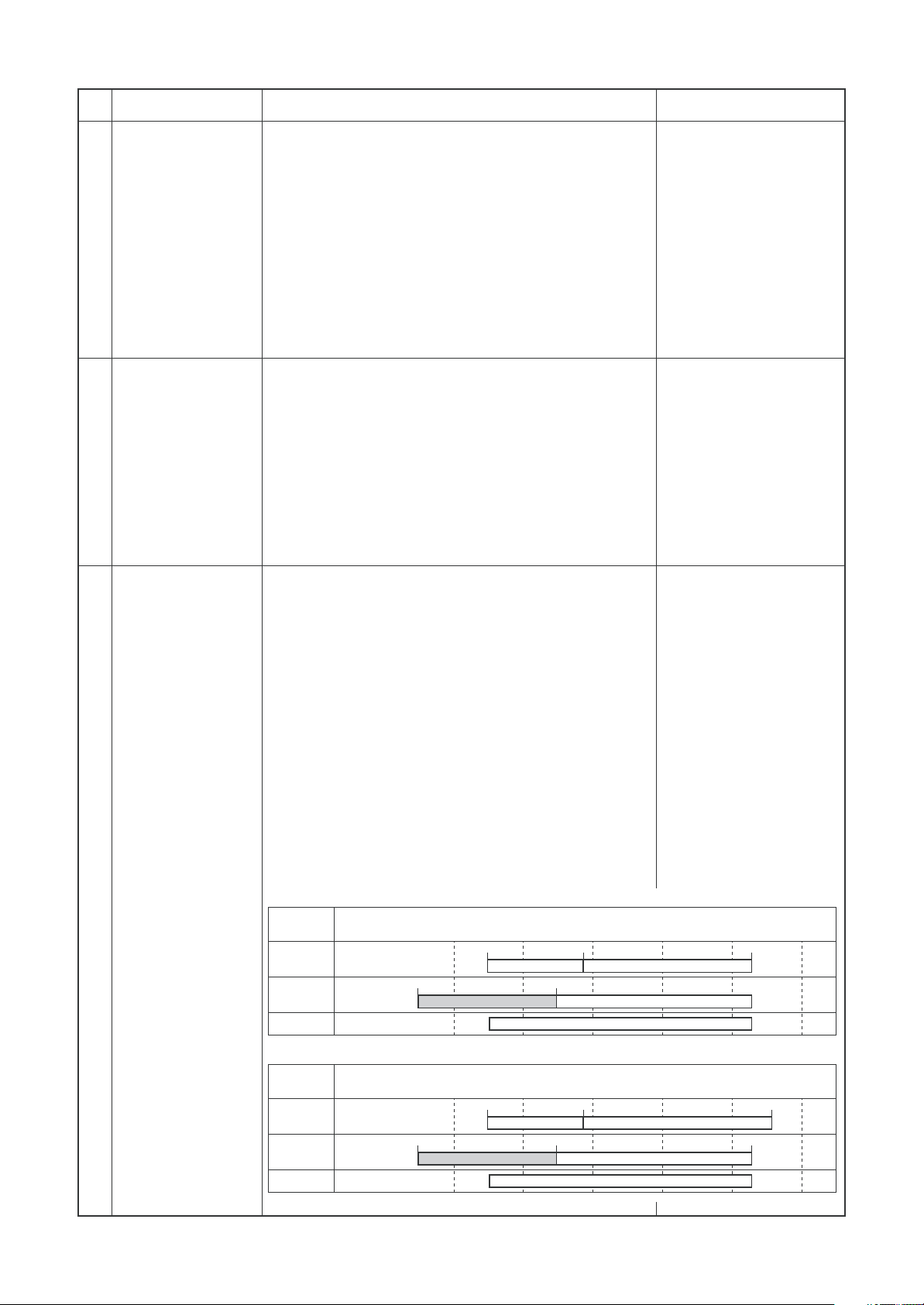
6
Fan control
7
Forced thermostat
OFF
Item
Outline of specifications
1) On the Outside Air Unit, HH tap only isprovided.
2) For 1 minute after operation start, the forced fan
OFF control is invalid.
3) There is no cool air discharge preventive control.
4) When refrigerant is recovered while cooling or fan
operation is selected, and when cooling oil is
recovered while heating operation is selected, the
fan continues operation.
However the priority is given to forced fan OFF
control
1) The thermostat is forcedly off by outdoor suction
temperature (TA).
• COOL: At TA < 66 ˚F [ 19 ˚C ]
•
HEAT: At TA > 59 ˚F [ 15 ˚C ] or TA < 23 ˚F [ – 5 ˚C ]
2) The thermostat is forcedly off by outdoor suction
temperature (TA) and remote control setting
temperature (TS).
• COOL: At TA < TS + 5.4 ˚F [ + 3 ˚C ]
• HEAT: At TA > TS – 5.4 ˚F [ – 3 ˚C ]
Remarks
8
Forced fan OFF
1) The thermostat is forcedly off by outdoor suction
temperature (TA).
• COOL/FAN: At TA < 41 ˚F [ 5 ˚C ]
• HEAT: At TA < 23 ˚F [ – 5 ˚C ]
2) After fan-OFF status continued for 60 minutes, turn
on the fan for 1 minute.
The forced fan-OFF status continues or released by
outdoor suction temperature (TA) in this time.
<Release conditions>
• COOL/FAN: At TA ≥ 41 ˚F [ 5 ˚C ]
• HEAT: At TA ≥ 23 ˚F [ – 5 ˚C ]
3) Other forced fan OFF release conditions
• Operation stop
• Operation mode exchange
•T
est run mode
Case to use in SMMS-i
Operation
mode
COOL
HEAT
FAN
[˚C]
˚F
[–10]
14
23 ˚F [ –5 ˚C] TS –5.4 ˚F [–3 ˚C]
[0]
32
41 ˚F [5 ˚C] TS +5.4 ˚F [3 ˚C] 109 ˚F [43 ˚C]
[10]
50
Outside temp.
[20]
68
FAN
Case to use in SMMS-e
Operation
mode
COOL
HEAT
FAN
[˚C]
˚F
[–10]
14
23 ˚F [ –5 ˚C] TS –5.4 ˚F [ –3 ˚C] 109 ˚F [43 ˚C]
[0]
32
41 ˚F [5 ˚C] TS +5.4 ˚F [3 ˚C] 115 ˚F [46 ˚C]
[10]
50
Outside temp.
[20]
68
FAN
Operation ready display
[30]
86
COOLFAN
FANHEAT
[30]
86
COOLFAN
FANHEAT
[40]
104
[40]
104
[50]
122
[50]
122
– 24 –
No.
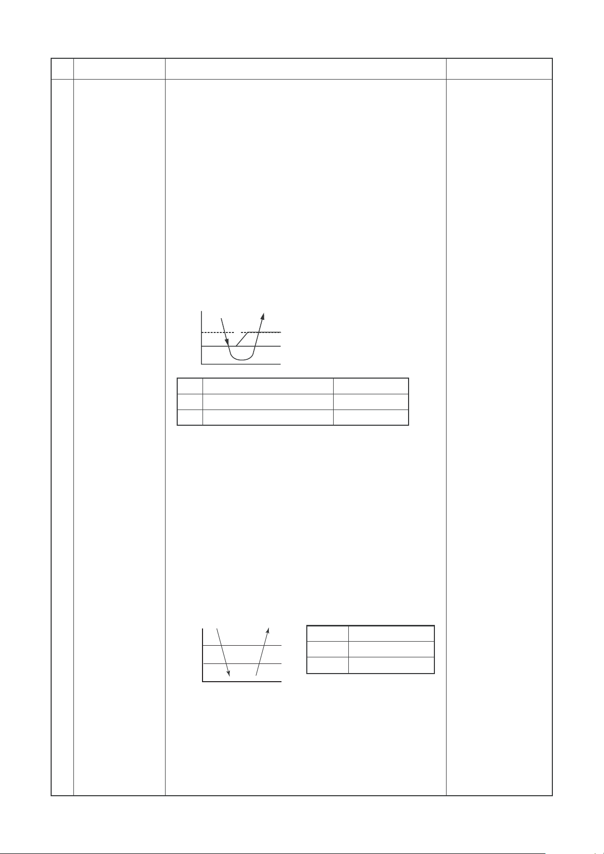
9
Freeze preventive
control
(Low temperature
release)
Item
Outline of specifications
1) The cooling operation is performed as follows based on
the detected temperature of TC1 sensor, TC2 sensor
and TCJ sensor.
• When [J] zone is detected for 5 minutes, thermostat is
forced to turn off.
• In [K] zone, timer counting pauses and is held.
• When [J] zone is detected, timer is cleared and returns
to normal operation.
• If thermostat is forcedly off by continuation of [J] zone,
indoor fan only operates until zone changes to [I] zone.
When the following conditions are satisfied, control
function resets.
<Reset conditions>
TC1 > 54 ˚F [ 12 ˚C ] and TC2 > 54 ˚F [ 12 ˚C ] and
TCJ > 54 ˚F [ 12 ˚C ]
20 minutes passed after stop
F˚ [ ˚C ]
P1
Q1
I
K
J
a
Remarks
TC1
P1
50 ˚F [ 10 ˚C ] (41 ˚F [ 5 ˚C ])
Q1
32 ˚F [ 0 ˚C ]
TC2, TCJ
14 ˚F [ –10 ˚C ]
7 ˚F [ –14 ˚C ]
( ) value:
When power supply is turned on, if
the value is under this temperature,
thermostat is forcedly off.
2) The cooling operation is performed as follows based on
the detected temperature of TC2 sensor and TCJ
sensor.
When [M] zone is detected for 45 minutes, thermostat
is forced to turn off.
In [N] zone, timer counting pauses and is held.
When shifting to [M] zone again, timer counting
restarts and continues.
When [L] zone is detected, timer is cleared and
operation returns to normal operation.
F˚ [ ˚C ]
P2
Q2
L
N
M
P2
Q2
TC2, TCJ
41 ˚F [ 5 ˚C ]
28 ˚F [ –2 ˚C ]
<Reset conditions>
TC1 > 54 ˚F [ 12 ˚C ] and TC2 > 54 ˚F [ 12 ˚C ] and
TCJ > 54 ˚F [ 12 ˚C ]
20 minutes passed after stop
– 25 –
No.
10
Cooling oil
(Refrigerant)
recovery control
11
Heating
refrigerant (oil)
recovery control
12
Short intermittent
operation compensation control
13
Remained heat
elimination
Item
Outline of specifications
When the indoor air conditioner which stops, in which
thermostat is off, or which operates [FAN] performs the
following control by receiving the cooling oil (refrigerant)
recovery signal from the outdoor unit.
Opens PMV of the indoor air conditioner with certain
opening angle.
When the indoor air conditioner which stops, in which
thermostat is off, or which operates [FAN] performs the
following control by receiving the heating refrigerant (oil)
recovery signal from the outdoor unit.
Opens PMV of the indoor air conditioner with certain
opening angle.
Detects temperature of TC2 and closes PMV.
1) For 5 minutes after start of operation, the operation
continues forcedly even if entering in thermostat OFF
condition.
(2) However cooling/heating selection, operation ready and
protective control are given with priority, and thermostat
is turned off.
1) If stopped from [HEAT] operation, the indoor fan operates
for approx. 30 seconds.
Remarks
• Recovery
operation is
usually performed
every 2 hours.
• Recovery
operation is
usually performed
every 1 hour.
14
Filter sign display
15 [Operation stand-by]
[Heating stand-by]
display
1) Estimates operation time of the indoor fan, sends the
filter exchange signal to remote control when the
specified time (2500H) passed and then displays it on
LCD.
2) Clears the estimate timer when received filter reset
signal from remote control.
In this time, if the specified time has passed, resets the
measured time and erases the LCD display.
<Ready stand-by>: displa displayed on the remote control.
1) When the following check codes are indicated.
• There is an indoor air conditioner which detected
indoor overflow [P10].
• There is an indoor air conditioner which detected
interlock warning [L30].
2) During forced thermo OFF.
• [COOL] operation is unavailable because other
indoor air conditioner operates in [HEAT] mode.
• COOL priority setting (Outdoor I/F P.C. board
SW11-bit1 is ON) is made, and other indoor air
conditioner operates in [COOL/DRY] mode.
Therefore [HEAT] operation is unavailable.
3) When fan stops by forced fan OFF control.
4) The above indoor air conditioners unavailable to
operate enter in [Standby] status with thermo-OFF.
•
[Operation stand-by]
display
<HEAT stand-by>: displayed on the remote control.
1) Defrosting
• Indoor fan stops because unit is under defrost
operation.
– 26 –
• [Heating stand-by]
display
No. Item Outline of specifications
Remarks
Central control
16
mode selection
1) The remote control at indoor air conditioner side
becomes able to select the operable contents ofthe
unit by setup at the central control side.
2) Setup contents
• In case of TCC-LINK central control
Operation from
TCC-LINK central
control
Single
[Central 1]
[Central 2]
[Central 3]
[Central 4]
(O : Operation available, × : Operation unavailable)
START/STOP Operation Timer Temp Air speed Air direction
setting selection setting setting setting setting
O
×
×
O
O
O
O
×
×
×
Operation on RBC-ATM32UL
O
×
×
O
O
O
O
×
×
O
—
—
—
—
—
* For the Outside Air Unit, setting functions for air speed and air direction are not provided.
In central control mode,
[Central control] display
(Lights up)
Display flashes when
item which operation
is prohibited was
changed from remote
control.
RBC-AMT32UL
—
—
—
—
—
[Central control]
display
– 27 –
9. APPLIED CONTROL AND FUNCTION
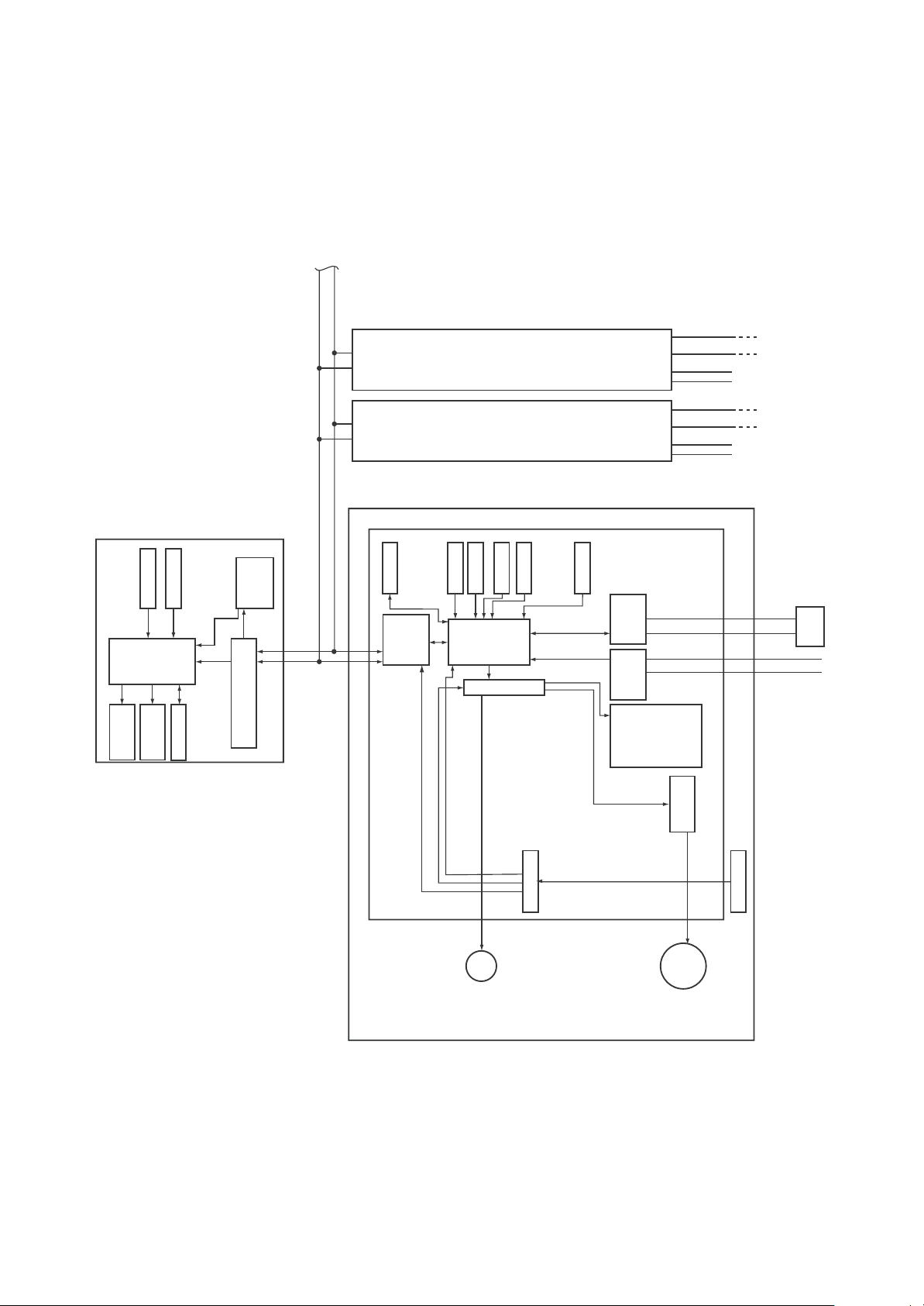
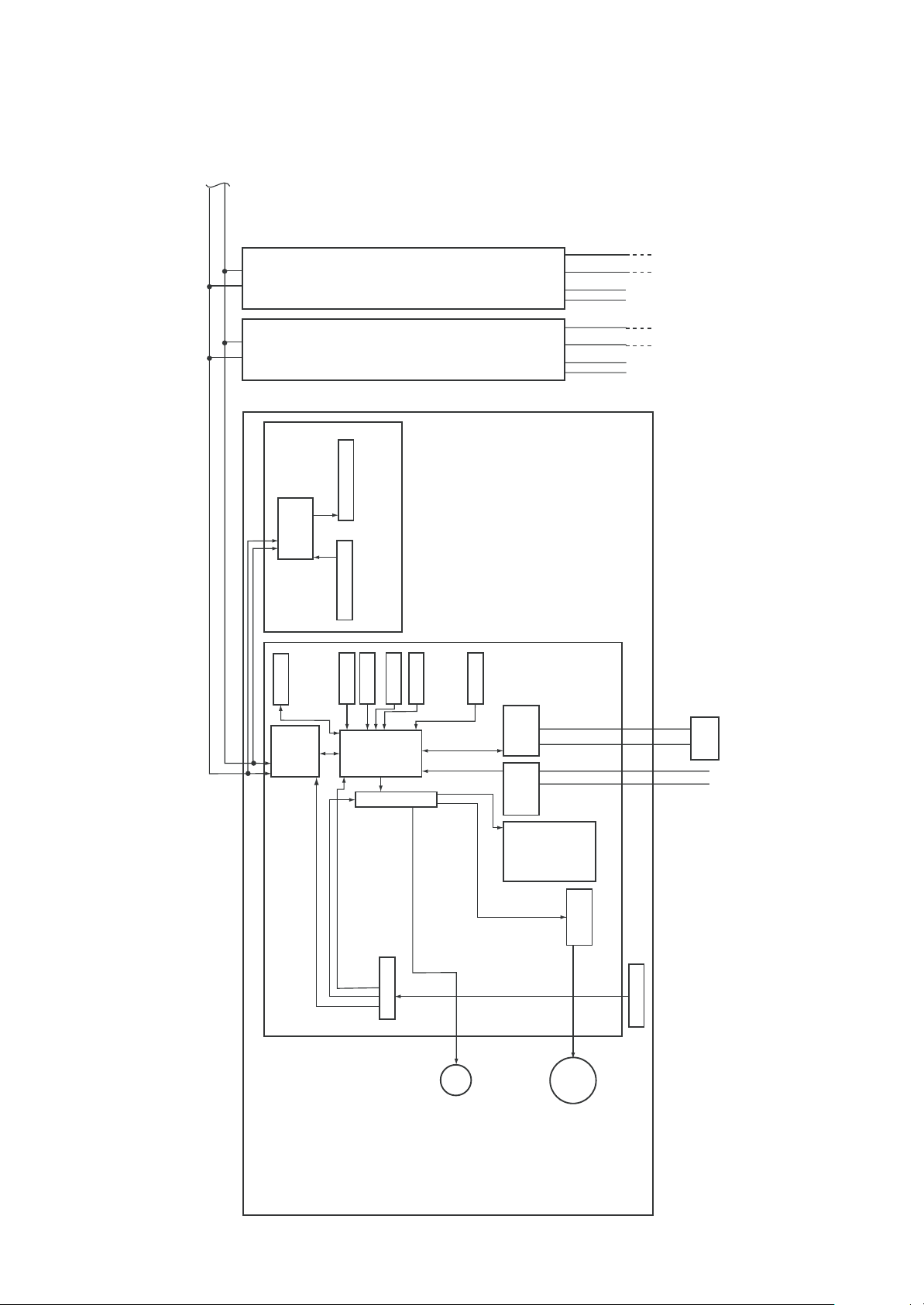
9-1. Indoor Control Block Diagram
9-1-1. When Main (Simple) Wired Remote Control Connected
unit
Power
source
Outdoor
L2
L1
A BAB
#2 #3
circuit
Power
Key switch
Function setting
CPU
supply
DC5V
AB
Remote control
LED
LCD
Display
Main (Simple) wired remote control (up to 2 units)
Display
EEPROM
communication circuit
EEPROM
circuit
control
Remote
communication
DC20V
DC12V
TA sensor
TC1 sensor
DC5V
TC2 sensor
CPU
H8/3039
Sameas left Sameas left
TCJ sensor
Driver
HA
BUS
AC
In operation
External output
U1 U2 U1 U2
L2
circuit
communication
synchronization
signal input circuit
Alarm
HEAT
COOL
Getting ready
Thermostat ON
Fan motor
L1
FAN
relay circuit
unit
Outdoor
Power
source
Indoor/outdoor communication
U2
unit
U1
Outdoor
U1 U2
L2
L1
Power source
208/230-1-60
Indoor control P. C. board (MCC-1403)
#1
Indoor unit
– 28 –
PMV
Power supply circuit
fan
Indoor
Transformer
motor
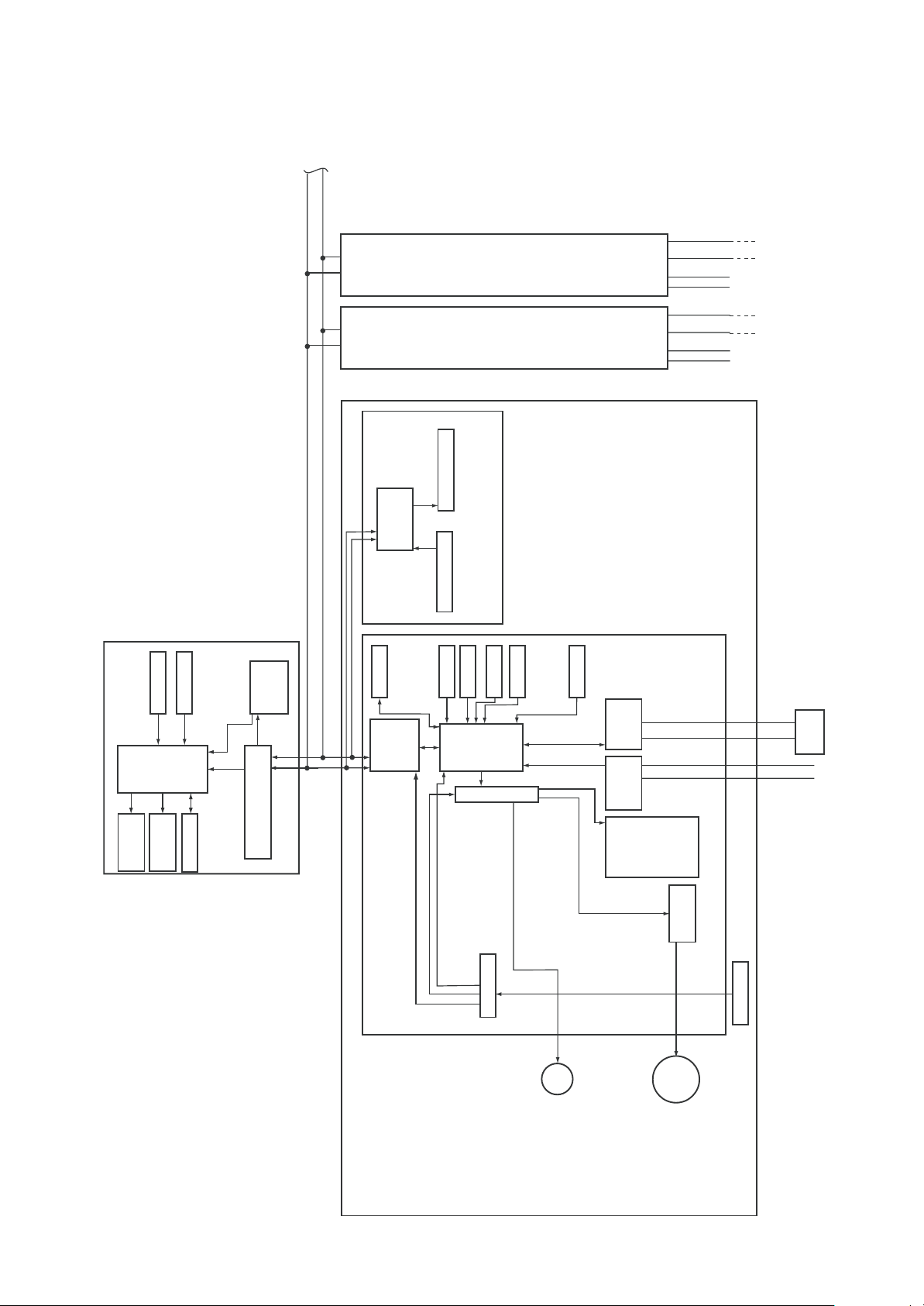
9-1-2. When Wireless Remote Control Kit Connected
Up to 8 units can be
connected.
L2
L1
Power
source
unit
Outdoor
#2 #3
Sensor P. C. board
Wireless remote control kit
Remote control
communication
circuit
EEPROM
circuit
control
Remote
AB AB AB
communication
Sameas left Sameas left
Display section
Sensor circuit
TA sensor
TC2 sensor
TC1 sensor
CPU
H8/3039
TCJ sensor
Driver
HA
U1 U2 U1 U2
BUS
circuit
communication
AC
synchronization
signal input circuit
unit
L2
L1
Outdoor
Power
source
U2
Indoor/outdoor communication
unit
U1
Outdoor
U1 U2
L2
L1
208/230-1-60
Power source
#1
Indoor unit
C. board (MCC-1403)
DC5V
DC20V
DC12V
Indoor control P.
Power supply circuit
PMV
– 29 –
In operation
External
output
Alarm
COOL
Thermostat ON
Getting ready
Indoor
FAN
HEAT
Fan motor
control circuit
fan
motor
Transformer
9-1-3. When Both Wired (Simple) Remote Control and
Wireless Remote Control Kit Connected
unit
Power
source
Outdoor
L2
L1
#2 #3
Wireless remote control kit
Remote control
EEPROM
Remote
AB AB AB
Key switch
Function setting
CPU
DC5V
circuit
Power
supply
Remote control
LCD
Display
LED
Display
EEPROM
communication circuit
Main (Simple) wired remote control (up to 2 units)
communication
circuit
circuit
control
communication
Sameas left Sameas left
Display section
Sensor circuit
TA sensor
TC2 sensor
TC1 sensor
CPU
H8/3039
TCJ sensor
Driver
HA
External
output
BUS
circuit
communication
AC
synchronization
signal input circuit
Alarm
In operation
Thermostat ON
Getting ready
U1 U2 U1 U2
L2
L1
HEAT
COOL
unit
Outdoor
Power
source
U2
Indoor/outdoor communication
unit
U1
FAN
Outdoor
U1 U2
L2
L1
208/230-1-60
Power source
#1
Indoor unit
C. board (MCC-1403)
DC5V
DC20V
DC12V
Indoor control P.
– 30 –
Power supply circuit
PMV
Fan motor
control circuit
fan
motor
Indoor
Transformer

9-1-4. Indoor Printed Circuit Board
/
MCC-1403
Remote control
power supply LED
/D203
HA (T10)
/CN061, DC12V
Optional output
/CN060, DC12V
Remote control
/CN41
Also used for communication of
PMV output
/CN082, DC12V
Power supply transformer (Secondary side)
(AC11V, 14V, 20V) /CN075
the central control system
/CN040
Microcomputer
operation LED
/D002
DISP /CN72, DC5V
CHK /CN071, DC5V
TC1 sensor
/CN100
TC2 sensor
/CN101
TCJ sensor
/CN102
External trouble
input/CN080
TA sensor
/CN104
Power supply
/CN067
Power supply
transformer
(Primary side)
/CN074
– 31 –
CN309
Optional
power supply
EXCT
/CN073, DC5V
AC fan output
/CN083

9-1-5. P.C. Board Optional Switch/Connector Specifications
Function
Ventilation output
HA
Option output
Connector
No.
CN032
CN061
CN060
Pin
No.
Specifications
DC12V
Output
Start/Stop input
0V (COM)
Remote control disabling
input
Operation output
DC12V (COM)
Alarm output
DC12V (COM)
Defrost output
Thermo-ON output
Cooling output
Heating output
Remarks
Setting at shipment: Linked operation; ON with indoor air
conditioner operation, OFF with stop
* Single operation setting by [VENT] button of remote
control is performed from remote control. (DN=31)
HA Start/Stop input (J01: Provided/None=
Pulse (At shipment from factory) / Static input selection)
Enables / disables start / stop control via remote
control
ON during operation (Answer back of HA)
ON during output of alarm
ON during defrosting of outdoor unit
ON during real thermo-ON (Compressor ON)
ON when operation mode is COOL
ON when operation mode is HEAT
Outside abnormal input
Filter option trouble
CHK operation check
DISP display mode
EXCT demand
CN080
CN070
CN071
CN072
CN073
Fan output
DC12V (COM)
DC12V (COM)
Outside abnormal input
Outside setting input
0V
Check mode input
0V
Display mode input
0V
Demand input
0V
ON when indoor fan is on
(When purifier is used / Interlock wiring)
The check code “L30” is generated continuously for 1
minute and the operation stops forcedly.
Setting of humidifier provided / none
(Short plug attached at shipment from factory)
This function is used to check indoor operation.
(The specified operation such as indoor fan “ON” is output
without communication with outdoor or remote control.)
This function enables the display mode to communicate
with indoor air conditioner and remote control only.
(When power supply is turned on) Timer short (Usually)
Forced thermo-OFF operation of indoor air conditioner.
– 32 –

9-2. Functions at test run
Cooling/Heating test run check
The test run for cooling/heating can be performed from either indoor remote control or outdoor interface
P.C. board.
1. Start/Finish operation of test run
Test run from indoor remote control
Wired remote control: Refer to the below item of “Test run” of the wired remote control.
In case of wired remote control
<RBC-AMT32UL>
Procedure
1
2
3
1,
FILTER
RESET
TEMP.
TEST
TIMER SET MODEFAN
TIME
SET
CL
SWING/FIX
SAVE
ON / OFF
VENT
UNIT LOUVER
5
Operation contents
Push [TEST] button for 4 seconds or more.
[TEST] is displayed at the display part and
the mode enters in TEST mode.
Push [ON/OFF] button.
Change the mode from [COOL] to [HEAT] using [MODE] button.
• Do not use [MODE] button for other mode except
[COOL]/[HEAT] modes.
• The temperature cannot be adjusted during test run.
• The trouble detection is performed as usual.
2,
4
3
TEST
TEST
4
5
Note) The test run returns to the normal operation after 60 minutes.
After test run, push [ON/OFF] button to stop the operation.
(Display on the display part is same to that in Procedure
Push [TEST] button to clear the TEST mode.
([TEST] display in the display part disappears and
status becomes the normal stop status.)
– 33 –
1
.)

Check function for operation of indoor unit (Functions at indoor unit side)
This function is provided to check the operation of the indoor unit singly without communication with the
remote control or the outdoor unit. This function can be used regardless of operation or stop of the system.
However, if using this function for a long time, a trouble of the equipment may be caused. Limit using this
function within several minutes.
[How to operate]
1) Short-circuit CHK pin (CN071 on the indoor P.C. board).
The operation mode differs according to the indoor unit status in that time.
Normal time: Both float SW and fan motor are normal.
Abnormal time: Either one of float SW or fan motor is abnormal.
2) Restricted to the normal time, if short-circuiting DISP pin (CN072 on the indoor P.C. board) in addition to
short-circuit of CHK pin (CN071 on the indoor P.C. board), the minimum opening degree (30pls) can be
set to the indoor PMV only.
When open DISP pin, the maximum opening degree (1500pls) can be obtained again.
[How to clear]
Open CHK pin. While the system is operating, it stops once but automatically returns to operation after
several minutes.
Short-circuit of CHK pin(CN071)
Fan motor
Indoor PMV (∗)
Communication
P.C. board LED
Normal time
DISP pin open(CN071) DISP pin short circuit(CN071)
(H) (H) Stop
Max. opening degree (1500pls)
All ignored All ignored All ignored
Lights Lights Flashes
Min. opening degree (30pls) Min. opening degree (30pls)
Abnormal time
– 34 –

9-3. Method to Set Indoor Unit Function DN Code
(When performing this task, be sure to use a wired remote control)
<Procedure> To be performed only when system at rest
1 Push the + + buttons simultaneously and hold for
at least 4 seconds.
The unit No. displayed first is the address of the header indoor unit in
group control.
Then the fan and louver of the selected indoor unit move.
2 Each time the “Select unit” side of the
UNIT LOUVER
button (button
of left side) is pushed, one of the indoor unit Nos. under
group control is displayed in turn.
Then the fan of the selected indoor unit move.
FILTER
RESET
3 Use the button to select the CODE No. (DN code) of
the desired function.
4 Use the button to select the desired SET DATA
3
associated with the selected function.
5 Push the button. (The display changes from flashing to
steady.)
• To change the selected indoor unit, go back to step 2.
• To change the selected function, go back to step 3.
SET DATA
TEST
SETTING
00 01
TEMP.
TEST
UNIT
1-1
R.C.
TIMER SET MODEFAN
TIME
SET
CL
SWING/FIX
54
6
12
No.
No.
SAVE
CODE No.
10
ON / OFF
VENT
UNIT LOUVER
6 When the button is pushed, the system returns to
normal off state.
– 35 –

Function Select Item No. (DN) Table
(Indicates items necessary to perform the applicable control at local site)
DN
01
Filter sign lighting time
02
Filter dirty degree
03
Central control address
04
Priority to specific indoor
air conditioner
0d
Cooling/Heating AUTO
mode provided / None
0F
Cooling only
10
Type
Item
Contents
0000: None 0001: 150H
0002: 2500H 0003: 5000H
0004: 10000H
0000: Standard
0001: Heavy dirt (Half of standard time)
0001: No.1 unit ~ 0064: No.64 unit
0099: Undefined
0000: No priority 0001: Priority
0000: AUTO Cooling/Heating provided
0001: No AUTO Cooling/Heating
(Automatic selection by connected outdoor unit)
0000: Heat pump
0001: Cooling only (No [AUTO] [HEAT] display)
0000: (1-way Air Discharge Cassette Type)
0001: (4-way Air Discharge Cassette Type)
~ 0037
At shipment from factory
0002: 2500H
0000: Standard
0099: Undefined
0000: No priority
0001: No AUTO
Cooling/Heating
0000: Heat pump
0016: Outside Air Unit
11
Indoor air conditioner
capacity
12
Line address
13
Indoor air conditioner
address
14
Group address
28
Automatic reset of power
failure
2E
HA terminal (T10)
selection
31
Fan (Single operation)
C8
Outside Air Unit
60 Timer setting
(wired remote control)
0000: Undefined 0001 ~ 0034
0001: No.1 unit ~ 0028: No.28 unit
0001: No.1 unit ~ 0064: No.64 unit
0000: Single 0001: Group master
0002: Group follower
0000: None 0001: Provided
0000: Normal (JEMA)
0001: Card input (shuffling omission)
0000: Unavailable 0001: Available
0000: Undefined 0001: Mixed
0000: Available (can be performed)
0001: Unavailable (cannot be performed)
According to capacity type
0099: Undefined
0099: Undefined
0099: Undefined
0000: None
0000: Normal
(HA terminal)
0000: Unavailable
0001: Mixed
0000: Available
92 Outside interlock
release condition
0000: Operation stop
0001: Release com munica tion signal receive
– 36 –
0000: Operation stop

Type
DN code “10”
Value Type Model
0016 Outside Air Unit MMD-AP
*1Default value stored in EEPROM mounted on service P.C. board
∗∗∗
Indoor Unit Capacity
DN code “11”
Value
0000*
0017
0021
0023
~
Capacity
Invalid
048 type
072 type
096 type
—
*1 Default value stored in EEPROM
mounted on service P.C. board
HF2UL
– 37 –

9-4. Applied Control in Indoor Unit
Remote location ON/OFF control box (TCB-IFCB-4UL)
[Wiring and setup]
• Use the exclusive connector for connection with the indoor control P.C. board.
• In a group control, the system can operate when connecting with any indoor unit (Control P.C. board) in
the group. However when taking out the operation/trouble signal from the other unit, it is necessary to take
out from each unit individually.
1. Control items
1) Start/Stop input signal : Operation start/stop in unit
2) Operation signal : Output during normal operation
3) Trouble signal : Output during alarm
(Serial communication trouble or indoor/outdoor protective device) operation
2. Wiring diagram using remote control interface (TCB-IFCB-4UL)
Input IFCB-4UL : No voltage ON/OFF serial signal
Output No voltage contact for operation, check display
Contact capacity: Below Max. AC240V 0.5A
Indoor control P.C. board
Start/Stop input
COM (GND)
Remote control prohibition/clear input
Operation signal output
COM (+12V)
Trouble signal output
1
2
3
4
5
6
CN61
T10
(YEL)
Remote location ON/OFF control box
(TCB-IFCB-4UL)
1
2
3
4
CN06
1
2
3
4
5
6
CN13
Power supply 208/230-1-60
ON/OFF serial
signal input
COM
Operation signal output
Check signal output
– 38 –

Ventilating fan control from remote control
[Function]
• The start/stop operation can be operated from the wired remote control when air to air heat exchanger or
ventilating fan is installed in the system.
• The fan can be operated even if the indoor unit is not operating.
• Use a fan which can receive the no-voltage A contact as an outside input signal.
• In a group control, the units are collectively operated and they can not be individually operated.
1. Operation
Handle a wired remote control in the following procedure.
∗ Use the wired remote control when turning off the system.
∗ Be sure to set up the wired remote control to the header unit. (Same in group control)
∗ In a group control, if the wired remote control is set up to the header unit, both header and follower units
are simultaneously operable.
1 Push concurrently + + buttons for 4 seconds or more.
The unit No. displayed firstly indicates the header indoor unit address in the group control.
In this time, the fan of the selected indoor unit turns on.
2 Every pushing
are displayed successively.
In this time, the fan of the selected indoor unit only turns on.
UNIT LOUVER
button (button of left side), the indoor unit numbers in group control
3 Using the temperature setup / button, specify the CODE No.
3131
31 .
3131
4 Using the timer time / button, select the SET DATA. (At shipment:
The setup data are as follows:
SET DATA
0000
0001
Handling of operation of air to air heat exchanger or ventilating fan
Unavailable (At shipment)
Available
5 Push button. (OK if display goes on.)
• To change the selected indoor unit, go to the procedure 2 ).
• To change the item to be set up, go to the procedure 3 ).
6 Pushing returns the status to the usual stop status.
2. Wiring
Relay (DC12V, procured locally)
Corresponds to the relay up
to one that the rated current
of the operation coil is approx. 16mA
CN032
FAN DRIVE
(2P WHI)
Indoor control
P.C. board
Note) Determine the cable length between the
indoor control P.C. board and the relay within 2m.
121
2
Outside control
input of fan
To terminal
Correspond up to a relay in which rated current of the
operation coil is approx. 16mA (Does not correspond to a
terminal block type relay on the market.)
00000000
0000 )
00000000
– 39 –

Leaving-ON prevention control
)
[Function]
• This function controls the indoor units individually. It is connected with cable to the control P.C. board of the
indoor unit.
• In a group control, it is connected with cable to the indoor unit (Control P.C. board), and the CODE No. 2E
is set to the connected indoor unit.
• It is used when the start operation from outside if unnecessary but the stop operation is necessary.
• Using a card switch box, card lock, etc, the indoor unit can be protected if it is forgotten to be turned off.
• When inserting a card, start/stop operation from the remote control is allowed.
• When taking out a card, the system stops if the indoor unit is operating and start/stop operation from the
remote control is forbidden.
1. Control items
1) Outside contact ON : The start/stop operation from the remote control is allowed.
(Status that card is inserted in the card switch box)
2) Outside contact OFF : If the indoor unit is operating, it is forced to stop.
(Start/Stop prohibited to remote control)
(Status that card is taken out from the card switch box)
* When the card switch box does not perform the above contact operation, convert it using a relay with b
contact.
2. Operation
Handle the wired remote control switch in the following procedure.
* Use the wired remote control switch when the system is being turned off.
1 Push concurrently + + buttons for 4 seconds or more.
2 Using the temperature setup / button, specify the CODE No.
3 Using the timer time / button, set
00010001
0001 to the setup data.
00010001
4 Push button.
5 Push button. (The status returns to the usual stop status.)
3. Wiring
CN073
(YEL)
Indoor control P.C. board
Determine the cable length between the indoor control P.C. board and the relay within 2m.
Note
T10
121
2
343
4
565
6
Power peak-cut from indoor unit
When the relay is turned on, a forced thermostat-OFF operation starts.
Relay (procured locally)
Power supply
* In the figure, the contact indicates
a status that the card is taken out.
Outside contact (Card switch box, etc: Procured locally)
2E2E
2E .
2E2E
• Wiring example
CN073
2
(2P plug: RED)
Indoor control P.C. board
EXCT
Relay (procured locally)
121
Relay coil signal
Note) Determine the cable length between the indoor or
outdoor control P.C. board and the relay within 2m.
– 40 –

2
ON / OFF
SETTEST
T
CL
SAVE
S
X
U
R
R.C.
TMODE
L
Address setup (Manual setting from Wired remote control)
In case that addresses of the indoor units will be determined prior to piping work after wiring work
• Set an indoor unit per a remote control.
• Turn on power supply.
(Example of 2-lines cabling)
(Real line: Wiring, Broken line: Refrigerant pipe)
1 Push + + buttons
simultaneously for 4 seconds or more.
Outdoor Outdoor
2 (Line address)
Using the temperature setup
buttons, set
1212
12 to the CODE No.
1212
/
Indoor Indoor Indoor Indoor Indoor
3 Using timer time / buttons, set
the line address.
4 Push button. (OK when display goes
on.)
5 (Indoor unit address)
Using the temperature setup
buttons, set
1313
13 to the CODE No.
1313
/
6 Using timer time / buttons, set 1
to the line address.
Line address 1
Indoor unit address 1
Group address 1
Header unit
For the above example, perform setting by connecting singly the
wired remote control without remote control inter-unit cable.
Group address
Individual : 0000
Header unit : 0001
Follower unit : 0002
1
2
2
1
3
2
Follower
unit
In case of group control
2
1
2
2
2
2
7 Push button. (OK when display goes
on.)
8 (Group address)
Using the temperature setup
buttons, set
1414
14 to the CODE No.
1414
/
SET DATA
SETTING
00 0 1
TEST
UNIT
A L
CODE No.
No.
10
No.
9 Using timer time / buttons, set
00000000
0000 to Individual,
00000000
Header unit and
10
Push button.
(OK when display goes on.)
11
Push button.
Setup completes.
(The status returns to the usual stop status.)
00010001
0001 to
00010001
00020002
0002 to follower unit.
00020002
, 5, 8
END
11
1
TIMER SE
RESE
<Operation procedure>
WING/FI
NIT LOUVE
3, 6, 9
4, 7, 10
1 2 3 4 5 6
7891011
Note 1)
When setting the line address from the remote control, do not use Address 29 and 30.
As they are addresses which cannot be set to the outdoor unit, if they are set, the check code [E04] (Indoor/
Outdoor communication circuit trouble) is issued.
Note 2)
When an address was manually set from the remote control and the central control over the refrigerant lines is
carried out, perform the following setting for the Header unit of each line.
• Set the line address for every line using SW13 and 14 on the interface P.C. board of the Header unit in each
line.
• Except the least line address No., turn off SW30-2 on the interface P.C. board of the Header units in the lines
connected to the identical central control.
(Draw the terminal resistances of indoor/outdoor and central control line wirings together.)
• For each refrigerant line, connect the relay connector between Header unit [U1U2] and [U3U4] terminals.
• After this, set the central control address.
(For setting of the central control address, refer to the Installation manual for the central control equipment.)
END
– 41 –

Confirmation of indoor unit No. position
1. To know the indoor unit addresses though position of the indoor unit is recognized
• In case of individual operation (Wired remote control : indoor unit = 1 : 1)
(Follow to the procedure during operation)
<Procedure>
1 Push button if the unit stops.
2 Push
UNIT LOUVER
button (button of left side).
Unit No. 1-1 is displayed on LCD.
(It disappears after several seconds.)
The displayed unit No. indicate line address and
indoor unit address.
(When other indoor units are connected to the
identical remote control (Group control unit), other
unit numbers are also displayed every pushing
UNIT LOUVER
button(button of left side).
TEMP.
FILTER
TEST
RESET
<Operation procedure>
TIMER SET
TIME
SET
F
ON / OFF
FAN
MODE
SAVE
VENT
CL
SWING/FIX
UNIT LOUVER
1
Operation
2
1 2
END
2. To know the position of indoor unit by address
• To confirm the unit No. in the group control
(Follow to the procedure during operation) (in this procedure, the indoor units in group control stop.)
<Procedure>
The indoor unit numbers in the group control are
successively displayed, and fan, louver, and drain
pump of the corresponding indoor unit are turned on.
(Follow to the procedure during operation)
1 Push and buttons simultaneously
for 4 seconds or more.
• Unit No. ALL is displayed.
• Fans of all the indoor units in the group control
operate.
2 Every pushing
UNIT LOUVER
button(button of left
side), the unit numbers in the group control
are successively displayed.
• The unit No. displayed at the first time indicates
the master unit address.
• Fan of the selected indoor unit only operate.
1
3
FILTER
RESET
TEMP.
TEST
TIMER SET
TIME
SET
CL
FAN
SAVE
SWING/FIX
ON / OFF
MODE
VENT
UNIT LOUVER
3 Push button to finish the procedure.
All the indoor units in the group control
stop.
<Operation procedure>
1 2 3
END
2
– 42 –

How to check all the unit No. from an arbitrary wired remote control
<Procedure>
The indoor unit No. and the position in the identical refrigerant piping can be checked.
An outdoor unit is selected, the identical refrigerant piping and the indoor unit No. are displayed one after the
other, and then its fan is on.
Carry out this procedure when the system is turned off.
1 Push the timer time button + simultaneously for 4 seconds or more.
First line 1 and CODE No.
ACAC
AC
(Address Change) are displayed. (Select outdoor unit.)
ACAC
Ø
2 Select line address using
UNIT LOUVER
/
SWING/FIX
button.
Ø
3 Determine the selected line address using button.
• The address of the indoor unit connected to the refrigerant piping of the selected outdoor unit is
displayed and the fan is on.
Ø
4 Every pushing
is displayed one after the other.
• Only fan of the selected indoor unit start operation.
UNIT LOUVER
button (button of left side), the indoor unit No. in the identical piping
Ø
[To select the other line address]
5 Push button and the operation returns to Procedure 2.
* The indoor address of other line can be continuously checked.
Ø
6 Push button and then the procedure finishes.
FAN
SAVE
SWING/FIX
ON / OFF
MODE
VENT
UNIT LOUVER
1
FILTER
RESET
TEMP.
TEST
TIMER SET
TIME
SET
CL
4
6
<Operation procedure>
1 2 3 4 5 6
2
35
END
– 43 –

How to change an indoor unit address by using a wired remote control
ON / OFF
T
CL
SAVE
S
X
UNIT
o.
R.C.
o.
TMODE
Use this method to change the address of indoor units (one to one or group control) that have had the original
address set automatically.
This procedure must be done while the units are not operating.
1 Simultaneously push and hold the “SET ”, “CL ”, and “TEST ” buttons for more
than 4 seconds. If there are 2 or more units in a group, the first “UNIT No.” indicated is the
header unit.
Ø
2 Push
change. If 2 or more units are controlled in a group the fan of the selected unit will be
energized.
UNIT LOUVER
button (button of left side) repeatedly to select an indoor unit address to
Ø
3 Push the TEMP. / buttons repeatedly to select
1313
13 for CODE No.
1313
Ø
4 Push the TIME / buttons repeatedly to change the value indicated in the SET DATA
section.
Ø
5 Push the “SET ” button, to save address.
Ø
6 Push
to change. Repeat steps 4 through 6 to continue changing indoor unit address and make
each of them unique.
7 Push
UNIT LOUVER
” button (button of left side) repeatedly to select another indoor unit addresses
UNIT LOUVER
button (button of left side) to review/confirm the revised addresses.
Ø
8 If the addresses have been changed correctly, push the “TEST ” button to finish the
procedure.
N
N
WING/FI
CODE No.
1
4
3
5
SET DATA
RESE
SETTING
00 00
TIMER SE
-
8
Fin
1
2, 6, 7
– 44 –

How to change all indoor addresses from an arbitrary wired remote control
(It is possible when setting has finished by automatic addresses.)
Contents: The indoor unit addresses in each identical refrigerant piping line can be changed from an
arbitrary wired remote control.
Enter in address check/change mode and then change the address.
<Procedure> Carry out this procedure during stop of system.
1 Push the timer time button + simultaneously for 4 seconds or more.
First line 1 and CODE No.
ACAC
AC (Address Change) are displayed.
ACAC
Ø
2 Select line address using
button.
UNIT LOUVER
/
SWING/FIX
Ø
FAN
SAVE
SWING/FIX
ON / OFF
MODE
VENT
UNIT LOUVER
3 Push the button.
• The address of the indoor unit connected to the
refrigerant piping of the selected outdoor unit is
displayed and the fan is on.
First the current indoor address is displayed.
(Line address is not displayed.)
1
FILTER
RESET
TEMP.
TEST
TIMER SET
TIME
SET
CL
Ø
4 button push up/down the indoor
address of the SET DATA.
The set data is changed to a new address.
Ø
5 Push button to determine the set data.
Ø
6 Every pushing
side), the indoor unit No. in the identical
piping is displayed one after the other.
• Only fan of the selected indoor unit start
operation.
Repeat the Procedures 4 to 6 to change all the
indoor addresses so that they are not duplicated.
UNIT LOUVER
button (button of left
Ø
7 Push button.
(All the indications of LCD go on.)
Ø
8 Push button and then the procedure
finishes.
3
Cancel of line selection
If the UNIT No. is not called up here, the outdoor unit
in that line does not exist.
CL
Push
Procedure
8
Finish
button to select a line again in the
2
.
FAN
SAVE
SWING/FIX
ON / OFF
MODE
VENT
UNIT LOUVER
FILTER
RESET
TEMP.
TEST
TIMER SET
TIME
SET
CL
2
4
6
5
<Operation procedure>
When you want to
complete the setting
7
1 2 3 4 5
6 7 8
END
– 45 –

Function to clear the check code
1. Clearing method from remote control
How to clear the check code of outdoor unit
The currently detected check code of the outdoor unit is cleared by using the service monitor function of
the remote control. (Check code of the indoor unit is not cleared.)
(Only the check code of the outdoor unit in one refrigerant line system is cleared.)
<Method>
1 Push + buttons simultaneously for 4 seconds or more to change the mode to service
monitor mode.
2 Push button to set the item code to [
FFFF
FF ].
FFFF
3 The display of A part in the following figure is counted as “
00020002
“
0002 ”
00020002
When “
* However counting from “0005 ” is repeated on the display screen.
00010001
ÆÆ
Æ “
0001 ”
ÆÆ
00010001
00000000
0000 ” appear, the check code was cleared.
00000000
00000000
ÆÆ
Æ “
0000 ” with 5-seconds interval.
ÆÆ
00000000
4 When pushing button, the status becomes normal.
3
2
FILTER
RESET
TEMP.
TEST
TIMER SET
TIME
SET
CL
SWING/FIX
FAN
SAVE
ON / OFF
MODE
VENT
UNIT LOUVER
00050005
0005 ”
00050005
ÆÆ
Æ “
ÆÆ
00040004
0004 ”
00040004
ÆÆ
Æ “
ÆÆ
00030003
0003 ”
00030003
ÆÆ
Æ
ÆÆ
4
<Operation procedure>
1
1 2 3 4
Returns to normal status
How to clear the check code of indoor unit
The check code of indoor unit is cleared by button of the remote control.
(Only the check code of the indoor unit connected with remote control to be operated is cleared.)
– 46 –

Monitoring function of remote control switch
When using the remote control (Model Name: RBC-AMT32UL), the following monitoring
function can be utilized.
Calling of display
<Contents>
The temperature of each sensor of the remote control, indoor unit and outdoor unit and the operating
status can be checked by calling the service monitor mode from the remote control.
<Procedure>
1 Push + buttons simultaneously for 4 seconds or more to call up the service monitor
mode.
The service monitor goes on and firstly the temperature of the CODE No.
0000
00 is displayed.
0000
Ø
2 Push button to change CODE No.
(CODE No.) to the CODE No. to be monitored.
For display code, refer to the following table.
Ø
3 Push
The sensor temperature of indoor unit or outdoor unit in its refrigerant line and the
operating status are monitored.
UNIT LOUVER
button (button of left side) to change to item to be monitored.
Ø
4 Push button to return the status to the normal display.
2
FILTER
RESET
TEMP.
TEST
TIMER SET
TIME
SET
CL
FAN
SAVE
SWING/FIX
ON / OFF
MODE
VENT
UNIT LOUVER
4
1
Returns to normal display
<Operation procedure>
1 2 3 4
3
– 47 –

< Based on the SMMS-e >
CODE No. Data name Display format Unit Remote control display example
3
Indoor unit data *
data
System
Room temperature(Use to control)
00
Room temperature(Remote control)
01
Indoor suction air temperature (TA)*
02
03
Indoor coil temperature (TCJ)*
04
Indoor coil temperature (TC2)*
05
Indoor coil temperature (TC1)*
06
Indoor discharge air temperature (TF)*
08
Indoor PMV opening
F3
Filter sign time
0A
No. of connected indoor units
0B
Total capacity of connected indoor units
0C
No. of connected outdoor units
0D
Total capacity of connected outdoor units
×1
1
1
1
1
2
×1
×1
×1
×1
×1
×1
×1/10
×1
×1
×10
×1
×10
°C
[0027] = 27°C
°C
°F
°F
[0080] = 80°F
°F
°F
°F
pls
[0150] = 1500pls
h
[2500] = 2500h
unit
[0048] = 48units
ton
[0215] = 21.5ton
unit
[0003] = 3units
ton
[0160] = 16ton
CODE No.
U3
U2
U1
30
20
10
4
11
12
13
15
16
17
18
19
1A
1C
1D
Outdoor unit individual data 1 *
1E
1F
CODE No.
U1
50
51
52
4
53 63 73
54 64 74
56
57
59
5A
5B
5D
5E
Outdoor unit individual data 2 *
5F
90
91
92
93
High-pressure sensor detention pressure (Pd)
31
21
Low-pressure sensor detention pressure (Ps)
32
22
Compressor 1 discharge temperature (TD1)
33
23
Compressor 2 discharge temperature (TD2)
35
25
Outdoor coil temperature (TE1)
36
26
Outdoor coil temperature (TE2)
37
27
Outdoor coil temperature (TG1)
38
28
Outdoor coil temperature (TG2)
39
29
Outside ambient temperature (TO)
3A
2A
Suction temperature (TS1)
3C
2C
Suction temperature (TS3)
3D
2D
Temperature at liquid side (TL1)
3E
2E
Temperature at liquid side (TL2)
3F
2F
Temperature at liquid side (TL3)
U3
U2
70
60
PMV1 opening
71
61
PMV3 opening
72
62
PMV4 opening
1 fan model : Compressor 1 curent (I1)
2 fan model : Compressor 1 and Outdoor fan 1 current (I1)
1 fan model : Compressor 2 and Outdoor fan 1 current (I2)
2 fan model : Compressor 2 and Outdoor fan 2 current (I2)
Compressor 1 revolutions
76
66
Compressor 2 revolutions
77
67
Outdoor fan mode
79
69
Compressor IPDU 1 heat sink temperature
7A
6A
Compressor IPDU 2 heat sink temperature
7B
6B
Outdoor fan IPDU 1 heat sink temperature
7D
6D
Outdoor fan IPDU 2 heat sink temperature
7E
6E
Outdoor unit capacity
7F
6F
Heating/cooling recovery controlled
–
–
Pressure release
–
–
Pressure release
–
–
Follower unit release (U2/U3 outdoor units)
–
–
Data name Display format Unit Remote control display example
×10
×10
×1
×1
×1
×1
×1
×1
×1
×1
×1
×1
×1
×1
Data name Display format Unit Remote control display example
×1
×1
×1
×10 A
×10 A
×10
×10
×1
×1
×1
×1
×1
×10
0:Normal
0:Normal
1:Release controlled
psi
[4350] = 435 psi
psi
°F
°F
°F
°F
°F
°F
[0080]= 80 °F
°F
°F
°F
°F
°F
°F
pls
[0500] = 500pls
pls
pls
[0135] = 13.5A
rps
[0642] = 64.2rps
rps
mode
[0058] = 58 mode
°F
°F
[0024] = 24 oF
°F
°F
ton
[0080] = 8 ton
[0010]=Heating recovery controlled
[0010]=Pressure release controlled
[0001]=Discharge temperature release controlled
[0100]=U2 outdoor unit release controlled
*1 The Outside Air Unit uses the revised sensor data, therefore the data below are not correctly displayed
because they are revised sensor data.
Indoor suction air temperature (TA)
Indoor coil temperature (TCJ)
Indoor coil temperature (TC2)
Indoor coil temperature (TC1)
*2 Only a part of indoor unit types is installed with the discharge air temperature sensor. This temperature is
not displayed for other types.
*3 When the units are connected to a group, data of the header indoor unit only can be displayed.
*4 The indications, U1, U2, U3 indicate the following outdoor units, respectively. For the indication data of each
outdoor unit, check CODE No.
U1...outdoor unit (Header unit)
U2...outdoor unit (Follower unit 1)
U3...outdoor unit (Follower unit 2)
– 48 –

< Based on the SMMS-i >
CODE No. Data name Display format Unit Remote control display example
3
Indoor unit data *
data
System
Room temperature(Use to control)
00
Room temperature(Remote control)
01
Indoor suction air temperature (TA)*
02
03
Indoor coil temperature (TCJ)*
04
Indoor coil temperature (TC2)*
05
Indoor coil temperature (TC1)*
06
Indoor discharge air temperature (TF)*
08
Indoor PMV opening
F3
Filter sign time
0A
No. of connected indoor units
0B
Total capacity of connected indoor units
0C
No. of connected outdoor units
0D
Total capacity of connected outdoor units
×1
1
1
1
1
2
×1
×1
×1
×1
×1
×1
×1/10
×1
×1
×10
×1
×10
°C
[0027] = 27°C
°C
°F
°F
[0080] = 80°F
°F
°F
°F
pls
[0150] = 1500pls
h
[2500] = 2500h
unit
[0048] = 48units
ton
[0215] = 21.5ton
unit
[0003] = 3units
ton
[0160] = 16ton
CODE No.
–
U2
U1
4
1A
1B
Outdoor unit individual data 1 *
1C
1D
1E
U1
4
5B
5D
Outdoor unit individual data 2 *
5E
20
10
21
11
22
12
23
13
24
14
25
15
26
16
27
17
28
18
29
19
2A
2B
2C
2D
2E
CODE No.
U2
60
50
61
51
62
52
63
53
64
54
65
55
66
56
67
57
68
58
6B
6D
6E
–
High-pressure sensor detention pressure (Pd)
–
Low-pressure sensor detention pressure (Ps)
–
Compressor 1 discharge temperature (TD1)
–
Compressor 2 discharge temperature (TD2)
–
Compressor 3 discharge temperature (TD3)
–
Suction temperature (TS1)
–
Outdoor coil temperature (TE1)
–
Outdoor coil temperature (TE2)
–
Outdoor coil temperature (TL)
–
Outside ambient temperature (TO)
–
PMV1,2 opening
–
PMV4 opening
–
Compressor 1 curent (I1)
–
Compressor 1 curent (I2)
–
Compressor 1 curent (I3)
–
–
Compressor 1 revolutions
–
Compressor 2 revolutions
–
Compressor 3 revolutions
–
Outdoor fan mode
–
Compressor IPDU 1 heat sink temperature
–
Compressor IPDU 2 heat sink temperature
–
Compressor IPDU 3 heat sink temperature
–
Outdoor fun IPDU 1 heat sink temperature
–
Heating/cooling recovery controlled
–
Pressure release
–
Pressure release
–
Follower unit release (U2/U3 outdoor units)
Data name Display format Unit Remote control display example
×10
×10
×1
×1
×1
×1
×1
×1
×1
×1
×1
×1
×10
×10
×10
Data name Display format Unit Remote control display example
×10
×10
×10
×1
×1
×1
×1
×1
0:Normal
0:Normal
1:Release controlled
psi
[4350] = 435 psi
psi
°F
°F
°F
°F
[0080]= 80 °F
°F
°F
°F
°F
pls
[0500] = 500pls
pls
A
[0135] = 13.5A
A
A
rps
rps
[0642] = 64.2rps
rps
mode
[0500] = 500pls
°F
°F
[0024] = 24 °F
°F
°F
[0010]=Heating recovery controlled
[0010]=Pressure release controlled
[0001]=Discharge temperature release controlled
[0100]=U2 outdoor unit release controlled
*1 The Outside Air Unit uses the revised sensor data, therefore the data below are not correctly displayed
because they are revised sensor data.
Indoor suction air temperature (TA)
Indoor coil temperature (TCJ)
Indoor coil temperature (TC2)
Indoor coil temperature (TC1)
*2 Only a part of indoor unit types is installed with the discharge air temperature sensor. This temperature is
not displayed for other types.
*3 When the units are connected to a group, data of the header indoor unit only can be displayed.
*4 The indications, U1, U2, U3 indicate the following outdoor units, respectively. For the indication data of each
outdoor unit, check CODE No.
U1...outdoor unit (Header unit)
U2...outdoor unit (Follower unit 1)
U3...outdoor unit (Follower unit 2)
– 49 –

Changing of settings for Celsius display
• Push button if the unit stops.
Procedure 1
Push simultaneously + + buttons for 4 seconds or more.
After a while, the display part flashes as shown right. Check the displayed CODE No. is [10 ].
• When the CODE No. is other than [10 ], push button to erase the display and repeat procedure from the
first step. (After pushing button, operation of the remote control is not accepted for approx. 1 minute.)
(For a group control, No. of the firstly displayed indoor unit becomes the header unit.)
4
3
5
6
1
2
SET DATA
Procedure 2
Every time the button is pushed,
UNIT LOUVER
(button at left side), the indoor unit No.
in the group control is displayed in order. Select the indoor unit of which setup
SETTING
R.C.
UNIT
No.
No.
is changed.
In this time, the position of the indoor unit of which setup is changed can be
confirmed because fan of the selected indoor unit will operate.
SET DATA
SETTING
Procedure 3
R.C.
UNIT
No.
No.
1. Using temp. setup buttons, specify CODE No. [33 ].
(CODE No. [33 ]: Fahrenheit display)
2. Using timer buttons, change the line address from [0001 ] to [0000 ]
3. Push button. In this time, the setup finishes when the display changes
SETTING
from flashing to lighting.
Procedure 4
After verifying the content change, push button. (Setup is determined.)
When pushing button, the display disappears and the status becomes the usual stop status.
(When pushing button the operation from the remote control is not accepted for approx. 1 minute.)
• If the operation from the remote control is not accepted after 1 minute of pushing the button, it is considered
that the address setup is incorrect. In this case, the automatic address must be set up again.
When changing the settings from Celsius to Fahrenheit follow the reverse order of the above procedure.
CODE No.
CODE No.
– 50 –

10. TROUBLESHOOTING
10-1. Overview
(1) Before engaging in troubleshooting
(a) Applicable models
All Super Module Multi (SMMS-i, SMMS-e) models.
(Indoor units: MM∗-AP
(b) Tools and measuring devices required
• Screwdrivers (Philips, flat head), spanners, long-nose pliers, nipper, pin to push reset switch, etc.
• Multimeter, thermometer, pressure gauge, etc.
(c) Things to check prior to troubleshooting (behaviors listed below are normal)
NO. Behavior Possible cause
A compressor would not start • Could it just be the 3-minute delay period (3 minutes after compressor
1
An indoor fan would not start • Isn’t the outside temp out of range of use temperature?
2
An outdoor fan would not start or would
3
change speed for no reason
An indoor fan would not stop • Could it just be the elimination of residual heat being performed as part of
4
The air conditioner would not respond to a
5
start/stop command from a remote control
, Outdoor units: MMY-MAP
∗∗∗
• Could it just be the air conditioner having the thermostat set to OFF?
• Could it just be the air conditioner operating in fan mode or put on the timer?
• Could it just be the system going through initial communication?
• Could it just be cooling operation under low outside temperature
• Could it just be defrosting operation?
• Could it just be the air conditioner operation under external or remote
)
∗∗∗∗
shutdown)?
conditions?
the air conditioner shutdown process after heating operation?
contro
l?
(2) Troubleshooting procedure
When a trouble occurs, proceed with troubleshooting in accordance with the procedure shown below.
"E28" trouble
Trouble
Check code
displayed on interface P.C. board
of header unit
Check code
displayed on interface P.C.
board of relevant follower unit
Any other trouble
Check trouble location
or trouble part
NOTE
Rather than a genuine trouble (see the List of Check Codes below), the problem could have been caused by a
microprocessor malfunction attributable to a poor quality of the power source or an external noise. Check for
possible noise sources, and shield the remote control wiring and signal wires as necessary.
– 51 –

10-2. Troubleshooting Method
The remote controls (main remote control and central control remote control) and the interface P.C. board of an
outdoor unit are provided with an LCD display (remote control) or a 7-segment display (outdoor interface P.C.
board) to display operational status. Using this self-diagnosis feature, the problem may be identified in the
event of a problem by following the method described below.
The list below summarizes check codes detected by various devices. Analyze the check code according to
where it is displayed and work out the nature of the problem in consultation with the list.
• When investigating a problem on the basis of a display provided on the indoor remote control or TCC-LINK
central control remote control - See the “TCC-LINK remote control or main remote control display” section of
the list.
• When investigating a problem on the basis of a display provided on an outdoor unit - See the “Outdoor 7-
segment display” section of the list.
• When investigating a problem on the basis of a wireless remote control-controlled indoor unit - See the “Light
sensor indicator light block” section of the list.
List of Check Codes (Indoor Unit)
(Check code detected by indoor unit)
Check code
TCC-LINK central
control or main
remote control
display
E03
E04
E08 E08
E10
E18
L30
Outdoor 7-segment display Indicator light block
Sub-code
––
––
––
––
Detected indoor unit No.
L30
Display of receiving unit
Operation
Timer Ready
Flash
SIM
IPDU: Intelligent Power Drive Unit (Inverter P.C. board)
: Lighting, : Flashing, : Goes off
ALT.: Flashing is alternately when there are two flashing LED
SIM: Simultaneous flashing when there are two flashing LED
Typical problem site Description of Check code
Indoor-remote control periodic
communication trouble
Indoor-outdoor periodic
communication trouble
Indoor inter-MCU communication
trouble
Trouble in periodic communication
between indoor header and
follower unit
Indoor heat exchanger
TLA––10F
temperature sensor (TCJ) trouble
Indoor heat exchanger
TLA––20F
temperature sensor (TC2) trouble
Indoor heat exchanger
TLA––30F
temperature sensor (TC1) trouble
Room air temperature sensor
TLA––01F
(TA/TSA) trouble
Discharge air temperature
TLA––11F
sensor (TF/TFA) trouble
MIS––92F
P.C. board or other indoor trouble
Duplicated indoor group header
MIS––30L
unit
Connection of group control cable
MIS––70L
to stand-alone indoor unit
MIS–80L80L
Indoor group address not set
MIS––90L
Indoor capacity not set
MIS––02L
Duplicated central control address
Indoor external trouble input
(interlock)
TLA––10P
Indoor AC fan trouble
TLA––13P
Other indoor unit trouble
Communication from remote control or network
adaptor has been lost (so has central control
communication).
Signals are not being received from outdoor unit.
MCU communication between main control and
motor microcontroller is faulty.
Periodic communication between indoor header
and follower units cannot be maintained.
Heat exchanger temperature sensor (TCJ) has
been open/short-circuited.
Heat exchanger temperature sensor (TC2) has
been open/short-circuited.
Heat exchanger temperature sensor (TC1) has
been open/short-circuited.
Room air temperature sensor (TA) has been
open/short-circuited.
Discharge air temperature sensor (TF) has been
open/short-circuited.
Indoor EEPROM is abnormal
(some other trouble may be detected).
There is more than one header unit in group.
There is at least one stand-alone indoor unit to
which group control cable is connected.
Address setting has not been performed for one or
more indoor units (also detected at outdoor unit
end).
Capacity setting has not been performed for indoor
unit.
There is duplication in central control address
setting.
Unit shutdown has been caused by external
trouble input (CN080).
Indoor AC fan trouble is detected (activation
of fan motor thermal relay).
Follower unit cannot be operated due to header unit
alarm (E03/L03/L07/L08).
.nwo sti ot lacitnedi sserdda stceted tinu roodnIsserdda roodni detacilpuDsserdda roodni detacilpuD
– 52 –

(Trouble detected by main remote control)
Main remote control
Check code
Outdoor 7-segment display Indicator light block
Sub-code
Display of receiving unit
Operation
Timer Ready
Typical fault site Description of trouble
Flash
E01 – –
E02 – –
E09 – –
No master remote control,
faulty remote control
communication (reception)
Faulty remote control
communication (transmission)
Duplicated master remote
control
Signals cannot be received from indoor unit;
master remote control has not been set
(including two remote control).
Signals cannot be transmitted to indoor unit.
Both remote controls have been set as
master remote control in two remote
control control (alarm and shutdown for
header unit and continued operation for
follower unit)
(Trouble detected by central control device)
Check code
TCC-LINK central
control
C05 – –
C06 – –
– – – Multiple network adapters
C12 – – –
P30 – –
Outdoor 7-segment display Indicator light block
Sub-code
Display of receiving unit
Operation
Timer Ready
No indication (when
main remote control
also in use)
As per alarm unit (see
above)
Flash
Typical fault site Description of trouble
Faulty central control
communication (transmission)
Faulty central control
communication (reception)
Blanket alarm for generalpurpose device control
interface
Group control follower unit
trouble
Central control device is unable to transmit
signal due to duplication of central control
device
Central control device is unable to receive
signal.
Multiple network adapters are connected to
remote control communication line
Device connected to general-purpose device
control interface for TCC-LINK is
Group follower unit is faulty (unit No. and
above detail [ ] displayed on main remote
control)
Note:The same trouble, e.g. a communication trouble, may result in the display of different check codes
depending on the device that detects it.
Moreover, check codes detected by the main remote control/central control device do not necessarily
have a direct impact on air conditioner operation.
faulty.
– 53 –

List of Check Codes (Outdoor Unit)
(Check code detected by SMMS-e and SMMS-i outdoor interface)
If “HELLO” is displayed on the oudoor 7-segment for 1 minute or more, turn off the power supply once and
then turn on the power supply again after 30 seconds or more. When the same symptom appears, it is
considered there is a possibility of I/F board trouble.
IPDU: Intelligent Power Drive Unit (Inverter P.C. board)
: Lighting, : Flashing, : Goes off
ALT.: Flashing is alternately when there are two flashing LED
SIM: Simultaneous flashing when there are two flashing LED
Check code
Outdoor 7-segment display
Sub-code
Number of indoor units from which
E06
signal is received normally
TCC-LINK
central control
or main remote
E07 – (E04)
E08 Duplicated indoor address
01: Indoor-outdoor communication
E12
02: Outdoor-outdoor
communication
E15 – E15
00: Overloading
E16
01: Number of units connected
00: No header unit
E19
02: Two or more header units
01: Connection of outdoor unit from
other refrigerant line
E20
02: Connection of indoor unit from
other refrigerant line
E23 – E23
E25 – E25
Address of outdoor unit from which
E26
signal is not received normally
D82E
A3-
Subcode
01
02
03
04
05
06
07
08
09
0A
0B
0C
Fan-
IPDU
IPDU
2
3
1
1
O
O
O
O
O
O
O
O
O
O
O
O
2
O
O
O
O
O
O
O
O
O
O
A3-
Sub-
IPDU
code
2
3
1
O
0D
0E
0F
11
12
13
18
19
1A
1B
O
O
O
O
O
O
O
O
O
O
O
O
O
O
Circle (O): Faulty IPDU
IPDU
1
O
O
O
O
O
O
O
Fan-
2
O
O
O
O
O
O
O
Display of receiving unit
Indicator light block
Operation
control
display
60E
(E08)
E12
E16
E19
E20
E26
82E.oN tinu roodtuo detcete
13E13E
Timer Ready
Typical problem site Description of problem
Flash
Signal lack of indoor unit
Indoor-outdoor
communication circuit
trouble
Duplicated indoor address
Automatic address starting
trouble
Indoor unit not found
during automatic address
setting
Too many indoor units
connected/overloading
Trouble in number of
outdoor header units
Connection to other
refrigerant line found
during automatic address
setting
Outdoor-outdoor
communication
transmission trouble
Duplicated follower
outdoor address
Signal lack of outdoor unit
Outdoor follower unit
trouble
IPDU communication
trouble
Sub MCU communication
Indoor unit initially communicating normally fails to
return signal (reduction in number of indoor units
connected).
Signal cannot be transmitted to indoor units
(
indoor units left without communication from
outdoor unit).
More than one indoor unit are assigned same
address (also detected at indoor unit end).
Indoor automatic address setting is started while
automatic address setting for equipment in other
refrigerant line is in progress.
Outdoor automatic address setting is started
while automatic address setting for indoor units
is in progress.
Indoor unit fails to communicate while automatic
address setting for indoor units is in progress.
Combined capacity of indoor units is too large
(more than 135% of combined capacity of outdoor
units).
There is no or more than one outdoor header unit
in one refrigerant line.
Indoor unit from other refrigerant line is detected
while indoor automatic address setting is in
progress.
Signal cannot be transmitted to other outdoor
units.
There is duplication in outdoor addresses set
manually.
Follower outdoor unit initially communicating
normally fails to do so (reduction in number of
follower outdoor units connected).
O
utdoor header unit detects fault relating to
follower outdoor unit (detail displayed on follower
outdoor unit).
There is no communication between IPDUs (P.C.
boards) in inverter box.
trouble
F05 –
01: TE1
F06
02: TE2
01: TL1
02: TL2
03: TL3
F05
Outdoor discharge
TLA40F–40F
temperature sensor (TD1)
trouble
Outdoor discharge
ALT
temperature sensor (TD2)
trouble
Outdoor heat exchanger
liquid side temperature
TLA60F
sensor (TE1, TE2) trouble
Outdoor liquid temperature
TLA70F70F
sensor (TL1, TL2, TL3)
trouble
Outdoor outside air
TLA80F–80F
temperature sensor (TO)
trouble
– 54 –
Outdoor discharge temperature sensor (TD1) has
been open/short-circuited.
Outdoor discharge temperature sensor (TD2) has
been open/short-circuited.
Outdoor heat exchanger liquid side temperature
sensors (TE1, TE2) have been open/shortcircuited.
Outdoor liquid temperature sensor (TL1, TL2,
TL3) has been open/short-circuited.
Outdoor outside air temperature sensor (TO) has
been open/short-circuited.

Check code
Outdoor 7-segment display
Sub-code
TCC-LINK
central control
or main remote
control
display
01: TG1
02: TG2
01: T
S1
03: TS3
–TLA32F32F
H05 – H05
H06 – H06
01: TK1 sensor trouble
02: TK2 sensor trouble
H08
03: TK3 sensor trouble
04: TK4 sensor trouble
05: TK5 sensor trouble
H08
H15 – H15
01: TK1 sensor trouble
02: TK2 sensor trouble
H16
03: TK3 sensor trouble
04: TK4 sensor trouble
05: TK5 sensor trouble
H16
H25 – H25
Number of priority indoor units
L06
(check code L05 or L06 depending
on individual unit)
L23
–
L23
Display of receiving unit
Indicator light block
Operation
Timer Ready
Flash
ALTF09F09
SIM
Typical problem site Description of problem
Outdoor heat exchanger
gas side temperature
sensor (TG1, TG2) trouble
Outdoor suction
temperature sensor
TLA21F21F
(TS1,TS3) trouble
Outdoor temperature
sensor (TE1,TL1)
TLA51F–51F
wiring trouble
Outdoor pressure sensor
TLA61F–61F
(Pd, Ps) wiring trouble
Low pressure sensor (Ps)
trouble
High pressure sensor (Pd)
TLA42F–42F
trouble
Outdooe EEPROM troubleMIS13F–13F
Outdoor discharge
temperature sensor (TD1)
wiring trouble
Activation of low-pressure
protectio
orp level lio woL70H–70H
Trouble in temperature
sensor for oil level
detection (TK1-TK5)
Outdoor discharge
temperature sensor (TD2)
wiring trouble
Oil level detection circuit
trouble
Outdoor discharge
temperature sensor (TD3)
wiring trouble
licated outdoor
Dup
MIS40L–40L
refrigerant line address
Duplicated priority indoor
MIS50L
unit (as displayed on
priority indoor unit)
Duplicated priority indoor
unit (as displayed on
MIS60L
indoor unit other than
Outdoor heat exchanger gas side temperature
sensors (TG1, TG2) have been open/
-short circuited.
Outdoor suction temperature sensor
(TS1,TS3) has been open/short-circuited.
Wiring trouble in outdoor temperature sensors
(TE1,TL1) has been detected.
Wiring trouble in outdoor pressure sensors (Pd,
Ps) has been detected.
Output voltage of low pressure sensor (Ps) is zero.
Output voltage of high pressure sensor (Pd) is zero
or provides abnormal readings when compressors
have been turned off.
Outd
oor EEPROM is faulty (alarm and shutdown
for header unit and continued operation for follower
unit)
Wiring/installation trouble or detachment of
outdoor discharge temperature sensor (TD1) has
been detected
Low pressure (Ps) sensor detects abnormally low
operating pressure.
Temperature sensor for oil level detection
noitcet
(TK1-TK5) detects abnormally low oil level.
Temperature sensor for oil level detection
(TK1-TK5) has been open/short-circuited.
Wiring/installation trouble or detachment of
outdoor discharge temperature sensor (TD2) has
been detected.
No temperature change is detected by
temperature sensor for oil level detection
(TK1-TK5) despite compressor having been
started.
Wiring/installation trouble or detachment of
outdoor discharge temperature sensor (TD3) has
been detected.
Identical refrigerant line address has been
assigned to outdoor units belonging to different
refrigerant piping systems.
More than one indoor unit have been set up as
priority indoor unit.
More than one indoor unit
as priority indoor unit.
priority indoor unit)
Indoor group address not
MIS)80L(–80L
set
oor model
Outd
MIS71L–71L
incompatibility trouble
SW setting mistake
Too many outdoor units
MIS82L–82L
connected
Address setting have not been performed for one
or more indoor units (also detected at indoor end).
Outdoor unit capacity has not been set (after P.C.
tes ton yticapac roodtuOMIS01L–01L
board replacement).
Old model outdoor unit (prior to 4 series) has been
connected.
Bit 3 and 4 of SW17 are turning on.
More than three outdoor units have been
connected.
have been set up
– 55 –

Outdoor 7-segment display
Sub-code
A3-
Sub-
IPDU
code
2
3
1
O
01
O
02
O
O
03
04
05
06
07
08
09
0A
0B
0C
O
O
O
O
O
O
O
O
O
O
O
O
O
00: Open phase detected
01: Compressor 1
P05
02: Compressor 2
03: Compressor 3
01: Compressor 1
P07
02: Compressor 2
03: Compressor 3
01: TS condition
P15
02: TD condition
Check code
Fan-
Sub-
IPDU
code
1
2
0D
0E
0F
11
12
13
18
19
O
1A
O
1B
O
O
Circle (O): Faulty IPDU
O
Display of receiving unit
TCC-LINK
central control
or main remote
control
display
A3-
Fan-
IPDU
IPDU
2
3
1
1
O
O
O
O
O
O
O
O
O
O
O
O
2
O
O
O
O
O
O
O
O
O
O
O
O
O
O
O
O
O
Indicator light block
Operation
71P–71P
Timer Ready
Typical problem site Description of problem
Flash
Trouble in number IPDUsMIS92L92L
Indoor external trouble
MIS)03L(.oN tinu roodni detceteD03L
input (interlock)
Outdoor discharge (TD1)
TLA30P–30P
temperature trouble
Open phase/power failure
Inverter DC voltage (Vdc)
TLA50P
trouble
MG-CTT trouble
Heat sink overheating
TLA70P
trouble
Outdoor liquid backflow
TLA31P–31P
detection trouble
Outdoor discharge (TD2)
TLA
temperature trouble
Outdoor discharge (TD3)
ALTP18–P18
temperature trouble
4-way valve reversing
TLA91Pdetceted .oN tinu roodtuO91P
trouble
Activation of high-pressure
TLA02P–02P
protection
revo tinu roodnITLA)01P(detceted .oN tinu roodnI01P
noitceted kael saGTLA51P
There are insufficient number of IPDUs (P.C.
boards) in inverter box.
Indoor unit has been shut down for external
trouble input in one refrigerant line (detected by
indoor unit).
Outdoor discharge temperature sensor (TD1) has
detected abnormally high temperature.
Open phase is detected when power is turned on.
Inverter DC voltage is too high (overvoltage) or too
low (undervoltage).
Temperature sensor built into IPM (TH) detects
overheating.
Indoor unit has been shutdown in one refrigerant
line due to detection of overflow (detected by
wolf
indoor unit).
State of refrigerant cycle circuit indicates liquid
backflow operation.
Outdoor suction temperature sensor (TS1) detects
sustained and repeated high temperatures that
exceed standard value.
Outdoor discharge temperature sensor (TD2)
detects abnormally high temperature.
Outdoor discharge temperature sensor (TD3)
detects abnormally high temperature.
Abnormality in refrigerating cycle is detected
during heating operation.
High pressure (Pd) sensor detects high pressure
that exceeds standard value.
MG-CTT: Magnet contactor
– 56 –

(Check code detected by IPDU featuring in SMMS-e and SMMS-i outdoor unit)
Check code
Outdoor 7-segment display
Sub-code
01: Compressor 1
F13 TLA31F
02: Compressor 2
03: Compressor 3
01: Compressor 1
H01
02: Compressor 2
03: Compressor 3
01: Compressor 1
H02
02: Compressor 2
03: Compressor 3
01: Compressor 1
H03
02: Compressor 2
03: Compressor 3
01: Compressor 1
P04
02: Compressor 2
03: Compressor 3
01: Compressor 1
P07
02: Compressor 2
03: Compressor 3
#0:Element short circuit
#1:Position detection circuit trouble
#3:Motor lock trouble
#4:Motor current trouble
P22
#C:TH Sensor temperature trouble
#D:TH Sensor short circuit/release
trouble
#E:Vdc voltage trouble
∗Put in Fan IPDU No. in [#] mark
TCC-LINK
central control
or main remote
control
display
Display of receiving unit
Indicator light block
Operation
H02
H03
Timer Ready
Typical problem site Description of proplem
Flash
Trouble in temperature
sensor built into indoor
IPM (TH)
Compressor trouble
(lockup)
Current detection circuit
trouble
Activation of high-pressure
TLA40P
SW
Heat sink overheating
TLA70P
trouble
Temperature sensor built into indoor IPM (TH)
has been open/short-circuited.
Inverter current (Idc) detection circuit detects
nwodkaerb rosserpmoC10H
overcurrent.
Compressor lockup is detected
Abnormal current is detected while inverter
compressor is turned off.
High-pressure SW is activated.
Temperature sensor built into IPM (TH) detects
overheating or has been short-circuited.
Outdoor fan IPDU detects trouble.Outdoor fan IPDU troubleTLA22P
01: Compressor 1
P26 TLA62P
02: Compressor 2
03: Compressor 3
01: Compressor 1
P29 TLA92P
02: Compressor 2
03: Compressor 3
Activation of IPM
short-circuit protection
Compressor position
detection circuit trouble
Short-circuit protection for compressor motor
driver circuit components is activated (momentary
overcurrent).
Compressor motor position detection trouble is
detected.
Note: The above check codes are examples only, and different check codes may be displayed depending on
the outdoor unit configuration
– 57 –

10-3. Troubleshooting Based on Information Displayed on
SET
T
SE
C
SAVE
S
I
E
ON / OF
U
R
Remote Control
Using main remote control (RBCAMT32UL)
(1) Checking and testing
When a fault occurs to an air conditioner, a check
code and indoor unit No. are displayed on the
display window of the remote control.
Check codes are only displayed while the air
conditioner is in operation.
If the display has already disappeared, access
trouble history by following the procedure
described below.
(2) Trouble history
The trouble history access procedure is
described below (up to four troubles stored in
memory).
Trouble history can be accessed regardless of
whether the air conditioner is in operation or shut down.
<Procedure> To be performed when system at rest
Check code
Indoor unit No. in which
fault has occurred
1 Invoke the SERVICE CHECK mode by pushing the +
buttons simultaneously and holding for at least 4
seconds.
The letters “ SERVICE CHECK” light up, and the check code
“01” is displayed, indicating the trouble history. This is
accompanied by the indoor unit No. to which the trouble history
is related and a check code.
2
2 To check other trouble history items, push the
bu another check code.
Check code “01” Check code “04” (oldest)
Note: Err i ntains four items.
3 When the button is pushed, normal display is
restored.
REQUIREMENT
Do not pu button as it would erase the whole trouble history of the indoor unit.
How to read displayed information
<7-segment display symbols>
TESTRE
3
TIMER SE
L
WING/F
NIT LOUVE
Normal display is restored.
1
Steps to follow
MOD
321
<Corresponding alphanumerical letters>
012 345 67 8 9 AbCdEFHJLP
– 58 –

Using indoor unit indicators (receiving unit light block) (wireless type)
To identify the check code, check the 7-segment display on the header unit. To check for check codes not displayed
on the 7-segment display, consult the “List of Check Codes (Indoor Unit)” in “10-2. Troubleshooting Method”.
: Goes off : Lighting : Blinking (0.5 seconds)
tluaf fo esuaCedoc kcehCkcolb thgiL
Operation Timer Ready
– Power turned off or trouble in wiring between receiving and indoor units
All lights out
Operation Timer Ready
Blinking
Operation Timer Ready
Blinking
E01 Faulty reception
E02 Faulty transmission
E03 Loss of communication
E08 Duplicated indoor unit No. (address)
E09 Duplicated master remote control
E10 Indoor unit inter-MCU communication trouble
E12 Automatic address starting trouble
E18 Trouble or poor contact in wiring between indoor units, indoor power turned off
E04
E06 Faulty reception in indoor-outdoor communication (
E07 Faulty transmission in indoor-outdoor communication
E15 Indoor unit not found during automatic address setting
E16 Too many indoor units connected/overloading
E19 Trouble in number of outdoor header units
E20 Detection of refrigerant piping communication trouble during automatic address setting
E23 Faulty transmission in outdoor-outdoor communication
E25 Duplicated follower outdoor address
E26 Faulty reception in outdoor-outdoor communication, Signal lack of outdoor unit
E28 Outdoor follower unit trouble
E31 IPDU communication trouble, sub MCU communication trouble
Trouble or poor contact in wiring between indoor and outdoor units
(loss of indoor-outdoor communication)
Receiving unit
Signal lack of indoor unit)
Trouble or poor contact in
wiring between receiving and
indoor units
Setting trouble
Operation Timer Ready
Alternate blinking
Operation Timer Ready
Alternate blinking
P01 Indoor AC fan trouble
P13 Outdoor liquid backflow detection trouble
P03 Outdoor discharge (TD1) temperature trouble
P04 Activation of outdoor high-pressure SW
P05
P07
P15 Gas leak detection - insufficient refrigerant charging
P17 Outdoor discharge (TD2) temperature trouble
P18 Outdoor discharge (TD3) temperature trouble
P19 Outdoor 4-way valve reversing trouble
P20 Activation of high-pressure protection
P22 Outdoor fan IPDU trouble
P26 Outdoor
P29 Compressor position detection circuit trouble
P31 Shutdown of other indoor unit in group due to fault (group follower unit trouble)
Open phase/power failure
Inverter DC voltage (Vdc) trouble
MG-CTT trouble
Outdoor heat sink overheating trouble - Poor cooling of electrical component (IPM) of outdoor unit
IPM short-circuit trouble
MG-CTT: Magnet contactor
– 59 –

Operation Timer Ready
Alternate blinking
Operation Timer Read
Alternate blinking
Operation
Timer Ready
tluaf fo esuaCedoc kcehCkcolb thgiL
F01
F02
F03
F10
F11
y
F04
F05
F06
F07
F08
F12
F13
F15
F16
F23 Low pressure sensor (Ps) trouble
F24
F29 Fault in indoor EEPROM
Heat exchanger temperature sensor (TCJ) trouble
Heat exchanger temperature sensor (TC2) trouble
Heat exchanger temperature sensor (TC1) trouble
Indoor unit temperature sensor
troubles
Ambient temperature sensor (TA/TSA) trouble
Discharge temperature sensor (TF) trouble
Discharge temperature sensor (TD1) trouble
Discharge temperature sensor (TD2) trouble
Heat exchanger temperature sensor (TE1, TE2) trouble
Liquid temperature sensor (TL1, TL2, TL3) trouble
Outdoor unit temperature
sensor troubles
Outside air temperature sensor (TO) trouble
Suction temperature sensor (TS1,TS3) trouble
Heat sink sensor (TH) trouble
Wiring trouble in heat exchanger sensor (TE1) and liquid temperature sensor (TL1)
Outdoor unit temperature sensor wiring/installation trouble
Wiring trouble in outdoor high pressure sensor (Pd) and low pressure sensor (Ps)
Outdoor pressure sensor wiring trouble
Outdoor unit pressure sensor
High pressure sensor (Pd) trouble
troubles
Synchronized blinking
Operation Timer Ready
Blinking
Operation
Operation
Timer Ready
Synchronized blinking
Timer Ready
Synchronized blinking
H01 Compressor breakdown
H02
H03
Compressor lockup
Current detection circuit trouble
Outdoor unit compressor or
A-3-IPDU related troubles
H05 Wiring/installation trouble or detachment of outdoor discharge temperature sensor (TD1)
H06 Abnormal drop in low-pressure sensor (Ps) reading
H07
H08
Abnormal drop in oil level
Trouble in temperature sensor for oil level detection circuit (TK1, TK2, TK3, TK4 or TK5)
Protective shutdown of outdoor
unit
H15 Wiring/installation trouble or detachment of outdoor discharge temperature sensor (TD2)
H16 Oil level detection circuit trouble - Trouble in outdoor unit TK1, TK2, TK3, TK4 or TK5 circuit
H25
Wiring/installation trouble or detachment of outdoor discharge temperature sensor (TD3)
L02 Outdoor unit model unmatched trouble
L03 Duplicated indoor group header unit
L05 Duplicated priority indoor unit (as displayed on priority indoor unit)
L06 Duplicated priority indoor unit (as displayed on indoor unit other than priority indoor unit)
L07 Connection of group control cable to stand-alone indoor unit
L08 Indoor group address not set
L09 Indoor capacity not set
L04 Duplicated outdoor refrigerant line address
L10 Outdoor capacity not set
L20 Duplicated central control address
L23 SW setting mistake
L24 Flow selector unit(s) setting trouble
L28 Too many outdoor units connected
L29 Trouble in number of IPDUs
L30 Indoor external interlock trouble
– 60 –

Light block Check code Cause of fault
y
y
y
Operation
Timer Read
F31 Outdoor EEPROM trouble
Synchronized blinking
Other (indications not involving check code)
Light block Check code Cause of fault
Operation Timer
Synchronized blinking
Operation Timer Read
Alternate blinking
Read
– Test run in progress
Setting incompatibility
–
(automatic cooling/heating setting for model incapable of it and heating setting for cooling-only
model)
– 61 –

10-4. Check Codes Displayed on Remote Control and SMMS-e and
SMMS-i Outdoor Unit (7-Segment Display on I/F Board) and
Locations to Be Checked
For other types of outdoor units, refer to their own service manuals.
Main
remote
control
E01 — —
E02 — —
E03 — —
E04 — —
E06 E06
— E07 —
E08 E08
E09 — —
E10 — —
E12 E12
E15 E15 —
Check code
Outdoor 7-segment display
Check
code
Sub-code
No. of indoor units from
which signal is received
normally
Duplicated indoor
address
01:
Indoor-outdoor
communication
02:
Outdoor-outdoor
communication
Location
of
detection
Remote
control
Remote
control
Indoor
unit
Indoor
unit
I/F Signal lack of
I/F Indoor-outdoor
Indoor
unit I/F
Remote
control
Indoor
unit
I/F Automatic
I/F Indoor unit not
Description System status
Indoor-remote
control
communication
trouble
(detected at
remote
control end)
Remote control
transmission
trouble
Indoor-remote
control
communication
trouble
(detected at
indoor end)
Indoor-outdoor
communication
circuit trouble
(detected at
indoor end)
indoor unit
communication
circuit trouble
(detected at
outdoor end)
Duplicated
indoor address
Duplicated
master remote
control
Indoor interMCU
communication
trouble
address starting
trouble
found during
automatic
address setting
Trouble detection
condition(s)
Stop of
corresponding
unit
Stop of
corresponding
unit
Stop of
corresponding
unit
Stop of
corresponding
unit
All stop Indoor unit initially
All stop Signal cannot be transmitted from
All stop More than one indoor unit are
Stop of
corresponding
unit
Stop of
corresponding
unit
All stop • Indoor automatic address setting
All stop Indoor unit cannot be
Communication between indoor
P.C. board and remote control is
disrupted.
Signal cannot be transmitted from
remote control to indoor unit.
There is no communication from
remote control (including wireless)
or network adaptor.
Indoor unit is not receiving signal
from outdoor unit.
communicating normally fails
to return signal for specified
length of time.
outdoor to indoor units for 30
seconds continuously.
assigned same address.
In two remote control configuration
(including wireless), both controls
are set up as master. (Header
indoor unit is shut down with alarm,
while follower indoor units continue
operating.)
Communication cannot be
established/maintained upon
turning on of power or during
communication.
is started while automatic address
setting for equipment in other
refrigerant line is in progress.
• Outdoor automatic address
setting is started while automatic
address setting for indoor units is
in progress.
detected after indoor
automatic address setting is
started.
Check items (locations)
• Check remote control inter-unit
tie cable (A/B).
• Check for broken wire or
connector bad contact.
• Check indoor power supply.
• Check for defect in indoor P.C.
board.
• Check remote control address
settings (when two remote
controls are in use).
• Check remote control P.C. board.
• Check internal transmission
circuit of remote control.
--- Replace remote control as
necessary.
• Check remote control and
network adaptor wiring.
• Check order in which power was
turned on for indoor and outdoor
units.
• Check indoor address setting.
• Check indoor-outdoor tie cable.
• Check outdoor terminating
resistor setting (SW30, Bit 2).
• Check power supply to indoor unit.
(Is power turned on?)
• Check connection of indooroutdoor communication cable.
• Check connection of
communication connectors on
indoor P.C. board.
• Check connection of
communication connectors on
outdoor P.C. board.
• Check for defect in indoor P.C.
board.
• Check for defect in outdoor P.C.
board (I/F).
• Check outdoor terminating
resistor setting (SW30, Bit 2).
• Check connection of indooroutdoor communication circuit.
• Check indoor addresses.
• Check for any change made to
remote control connection
(group/individual) since indoor
address setting.
• Check remote control settings.
• Check remote control P.C.
boards.
• Check for defect in indoor P.C.
board
• Perform automatic address
setting again after disconnecting
communication cable to that
refrigerant line.
• Check connection of indooroutdoor communication line.
• Check for trouble in indoor power
supply system.
•
Check for noise from other devices.
• Check for power failure.
• Check for defect in indoor P.C.
board.
– 62 –

Main
Check code
Outdoor 7-segment display
remote
Check
control
code
00:
Overloading
01-:
No. of units connected
Sub-code
Location
detection
I/F Too many
E16 E16
E18 — — Indoor
00:
No header unit
02:
E19 E19
E20 E20
Two or more header
units
01:
Connection of outdoor
unit from other line
02:
Connection of indoor
unit from other line
unit
I/F Trouble in
I/F Connection to
I/F Outdooroutdoor
E23 E23 —
E25 E25 —
Address of outdoor unit
from which signal is not
received normally
I/F Duplicated
I/F Signal lack of
E26 E26
Detected outdoor unit
No.
I/F Outdoor
E28 E28
of
Description System status
indoor units
connected
Trouble in
communication
between indoor
header and
follower units
number of
outdoor header
units
other line found
during
automatic
address setting
communication
transmission
trouble
follower outdoor
address
outdoor unit
follower unit
trouble
Trouble detection
condition(s)
All stop • Combined capacity of indoor units
Stop of
corresponding
unit
All stop • There are more than one outdoor
All stop Equipment from other line is found
All stop Signal cannot be transmitted to
All stop There is duplication in outdoor
All stop Outdoor unit initially
All stop Outdoor header unit receives
exceeds 135% of combined
capacity of outdoor units.
Note:
If this code comes up after
backup setting for outdoor unit
failure is performed, perform
“No overloading detected”
setting.
<“No overloading detected” setting
method>
Turn on SW09/Bit 2 on I/F
P.C. board of outdoor header
unit.
• More than 64 indoor units are
connected.
Periodic communication between
indoor header and follower units
cannot be maintained.
header units in one line.
• There is no outdoor header unit in
one line.
to have been connected when
indoor automatic address setting is
in progress.
other outdoor units for at least 30
seconds continuously.
addresses set manually.
communicating normally fails
to return signal for specified
length of time.
trouble code from outdoor follower
unit.
Check items (locations)
• Check capacities of indoor units
connected.
• Check combined HP capacities of
indoor units.
• Check HP capacity settings of
outdoor units.
• Check No. of indoor units
connected.
• Check for defect in outdoor P.C.
board (I/F).
• Check remote control wiring.
• Check indoor power supply wiring.
• Check P.C. boards of indoor units.
Outdoor header unit is
outdoor unit to which indooroutdoor
tie cable (U1,U2) is
connected.
• Check connection of indooroutdoor communication line.
• Check for defect in outdoor P.C.
board (I/F).
Disconnect inter-line tie cable in
accordance with automatic address
setting method explained in
“Address setting” section.
• Check power supply to outdoor
units. (Is power turned on?)
• Check connection of tie cables
between outdoor units for bad
contact or broken wire.
• Check communication connectors
on outdoor P.C. boards.
• Check for defect in outdoor P.C.
board (I/F).
• Check termination resistance
setting for communication
between outdoor units.
Note:
Do not set outdoor addresses
manually.
• Backup setting is being used for
outdoor units.
• Check power supply to outdoor
unit. (Is power turned on?)
• Check connection of tie cables
between outdoor units for bad
contact or broken wire.
• Check communication connectors
on outdoor P.C. boards.
• Check for defect in outdoor P.C.
board (I/F).
• Check check code displayed on
outdoor follower unit.
<Convenient functions>
If SW04 is pressed and held for at
least 1 second while [E28] is
displayed on the 7-segment display
of outdoor header unit, the fan of
the outdoor unit that has been shut
down due to an trouble comes on.
If SW04 and SW05 are pressed
simultaneously, the fans of normal
outdoor units come on.
To stop the fan or fans, press
SW05 on its own.
– 63 –

Main
Outdoor 7-segment display
remote
control
E31 E31
Check
code
Sub-code
Subcode
1
O
01
02
O
03
04
O
05
06
O
07
08
O
09
0A
O
0B
0C
O
0D
0E
O
0F
O
11
12
O
13
18
O
19
1A
O
1B
Circle (O): Faulty IPDU
F01 — —
F02 — —
F03 — —
F04 F04 —
F05 F05 —
Check code
01: TE1 sensor trouble
02: TE2 sensor trouble
F06 F06
01: TL1 sensor trouble
02: TL2 sensor trouble
F07 F07
03: TL3 sensor trouble
F08 F08 —
02: TG2 sensor trouble
F09 F09
F10 — —
A3-
IPDU
Location
of
detection
Fan-
I/F IPDU
IPDU
2
3
1
2
O
O
O
O
O
O
O
O
O
O
O
O
O
O
O
O
O
O
O
O
O
O
O
O
O
O
O
O
O
O
O
O
O
O
O
O
O
O
O
80
Indoor
unit
Indoor
unit
Indoor
unit
I/F TD1 sensor
I/F TD2 sensor
I/F TE1/TE2
I/F TL1 sensor
I/F TO sensor
I/F01: TG1 sensor trouble
Indoor
unit
Description System status
communication
trouble
Communication
trouble between
MCU and Sub
MCU
Indoor TCJ
sensor trouble
Indoor TC2
sensor trouble
Indoor TC1
sensor trouble
trouble
trouble
sensor trouble
trouble
trouble
TG1/TG2
sensor trouble
Indoor TA
sensor trouble
All stop Communication is disrupted
All stop Communication between MCU and
Stop of
corresponding
unit
Stop of
corresponding
unit
Stop of
corresponding
unit
All stop Sensor resistance is infinity or zero
All stop Sensor resistance is infinity or zero
All stop Sensor resistance is infinity or zero
All stop Sensor resistance is infinity or zero
All stop Sensor resistance is infinity or zero
All stop Sensor resistance is infinity or zero
Stop of
corresponding
unit
Trouble detection
condition(s)
between IPDUs (P.C.
boards) in inverter box.
Sub MCU stopped.
Sensor resistance is infinity or zero
(open/short circuit).
Sensor resistance is infinity or zero
(open/short circuit).
Sensor resistance is infinity or zero
(open/short circuit).
(open/short circuit).
(open/short circuit).
(open/short circuit).
(open/short circuit).
(open/short circuit).
(open/short circuit).
Sensor resistance is infinity or zero
(open/short circuit).
Check items (locations)
• Check wiring and connectors
involved in communication
between IPDU-I/F P.C. board for
bad contact or broken wire.
• Check for defect in outdoor P.C.
board (I/F, A3-IPDU or Fan IPDU).
• Check for external noise.
• Operation of power supply reset
(OFF for 60 seconds or more)
• Outdoor I/F PC board trouble
check
• Check connection of TCJ sensor
connector and wiring.
• Check resistance characteristics
of TCJ sensor.
• Check for defect in indoor P.C.
board.
• Check connection of TC2 sensor
connector and wiring.
• Check resistance characteristics
of TC2 sensor.
• Check for defect in indoor P.C.
board.
• Check connection of TC1 sensor
connector and wiring.
• Check resistance characteristics
of TC1 sensor.
• Check for defect in indoor P.C.
board.
• Check connection of TD1 sensor
connector.
• Check resistance characteristics
of TD1 sensor.
• Check for defect in outdoor P.C.
board (I/F).
• Check connection of TD2 sensor
connector.
• Check resistance characteristics
of TD2 sensor.
• Check for defect in outdoor P.C.
board (I/F).
• Check connection of TE1/TE2
sensor connectors.
• Check resistance characteristics
of TE1/TE2 sensors.
• Check for defect in outdoor P.C.
board (I/F).
• Check connection of TL1/TL2/TL3
sensor connector.
• Check resistance characteristics
of TL1/TL2/TL3 sensor.
• Check for defect in outdoor P.C.
board (I/F).
• Check connection of TO sensor
connector.
• Check resistance characteristics
of TO sensor.
• Check for defect in outdoor P.C.
board (I/F).
• Check connection of TG1/TG2
(open/short circuit).
• Check resistance characteristics
of TG1/TG2 sensors.
• Check for defect in outdoor P.C.
board (I/F).
• Check connection of TA sensor
connector and wiring.
• Check resistance characteristics
of TA sensor.
• Check for defect in indoor P.C.
board.
– 64 –

Main
Outdoor 7-segment display
remote
control
Check
code
Sub-code
F11 — —
Check code
01: TS1 sersor trouble
F12 F12
F13 F13
03: TS3 sersor trouble
01: Compressor 1 side
02: Compressor 2 side
03: Compressor 3 side
F15 F15 —
Location
of
detection
Indoor
unit
I/F TS1/TS3
IPDU TH sensor
I/F Outdoor
Description System status
Indoor TF
sensor trouble
sensor trouble
trouble
temperature
sensor wiring
trouble (TE1,
TL1)
Trouble detection
condition(s)
Stop of
corresponding
unit
All stop Sensor resistance is infinity or zero
All stop Sensor resistance is infinity or zero
All stop During compressor operation in
Sensor resistance is infinity or zero
(open/short circuit).
(open/short circuit).
(open/short circuit).
HEAT mode, TL1 continuously
provides temperature reading
higher than indicated by TL1 by at
least specified margin for 3 minutes
or more.
Check items (locations)
• Check connection of TF sensor
connector and wiring.
• Check resistance characteristics
of TF sensor.
• Check for defect in indoor P.C.
board.
• Check connection of TS1/TS3
sensor connector.
• Check resistance characteristics
of TS1/TS3 sensor.
• Check for defect.
• Defect in IPM built-in temperature
sensor
→ Replace A3-IPDU P.C. board.
• Check installation of TE1 and TL1
sensors.
• Check resistance characteristics
of TE1 and TL1 sensors.
• Check for outdoor P.C. board
(I/F) trouble.
F16 F16 —
F23 F23 —
F24 F24 —
F29 — —
F31 F31 —
01: Compressor 1 side
02: Compressor 2 side
H01 H01
03: Compressor 3 side
01: Compressor 1 side
02: Compressor 2 side
03: Compressor 3 side
H02 H02
01: Compressor 1 side
H03 H03
*1 Total shutdown in case of header unit
Continued operation in case of follower unit
02: Compressor 2 side
03: Compressor 3 side
I/F Outdoor
I/F Ps sensor
I/F Pd sensor
Indoor
unit
I/F Outdoor
IPDU Compressor
IPDU Compressor
IPDU Current
pressure
sensor wiring
trouble (Pd, Ps)
trouble
trouble
Other indoor
trouble
EEPROM
trouble
breakdown
trouble (lockup)
MG-CTT trouble
detection
circuit trouble
All stop Readings of high-pressure Pd
sensor and lowpressure Ps sensor
are switched.
Output voltages of both sensors
are zero.
All stop Output voltage of Ps sensor is zero. • Check for connection trouble
All stop Output voltage of Pd sensor is zero
Stop of
corresponding
unit
All stop *1 Outdoor P.C. board (I/F) does not
All stop Inverter current detection circuit
All stop Overcurrent is detected several
All stop Current flow of at least specified
(sensor open-circuited).
Pd > 4.15MPa despite compressor
having been turned off.
Indoor P.C. board does not operate
normally.
operate normally.
detects overcurrent and shuts
system down.
seconds after startup of inverter
compressor.
magnitude is detected despite
inverter compressor having been
shut turned off.
• Check connection of highpressure
Pd sensor connector.
• Check connection of lowpressure
Ps sensor connector.
• Check for defect in pressure
sensors Pd and Ps.
• Check for trouble in outdoor P.C.
board (I/F).
• Check for deficiency in
compressive output of
compressor.
involving Ps sensor and Pd
sensor connectors.
• Check connection of Ps sensor
connector.
• Check for defect in Ps sensor.
• Check for deficiency in
compressive output of
compressor.
• Check for defect in 4-way valve.
• Check for defect in outdoor P.C.
board (I/F).
• Check for defect in SV4 circuit.
• Check connection of Pd sensor
connector.
• Check for defect in Pd sensor.
• Check for defect in outdoor P.C.
board (I/F).
• Check for defect in indoor P.C.
board (faulty EEPROM)
• Check power supply voltage.
• Check power supply noise.
• Check for defect in outdoor P.C.
board (I/F).
• Check power supply voltage.
(AC460V ± 10%).
• Check for defect in compressor.
• Check for possible cause of
abnormal overloading.
• Check for defect in outdoor P.C.
board (A3-IPDU).
• Check for defect in compressor.
• Check power supply voltage.
(AC460V ± 10%).
• Check compressor system wiring,
particularly for open phase.
• Check connection of connectors/
terminals on A3-IPDU P.C. board.
• Check conductivity of case heater.
(Check for refrigerant problem
inside compressor.)
• Check for defect in outdoor P.C.
board (A3-IPDU).
• Check outdoor MG-CTT.
• Check current detection circuit
wiring.
• Check defect in outdoor P.C.
board (A3-IPDU).
MG-CTT: Magnet contactor
– 65 –

Main
Outdoor 7-segment display
remote
control
Check
code
Sub-code
H05 H05 —
H06 H06 —
H07 H07 —
Check code
01: TK1 sensor trouble
02: TK2 sensor trouble
03: TK3 sensor trouble
04: TK4 sensor trouble
05: TK5 sensor trouble
H08 H08
H15 H15 —
Location
of
detection
I/F TD1 sensor
I/F Activation of
I/F Low oil level
I/F Trouble in
I/F TD2 sensor
Description System status
miswiring
(incomplete
insertion)
low-pressure
protection
protection
temperature
sensor for oil
level detection
miswiring
(incomplete
insertion)
Trouble detection
condition(s)
All stop Discharge temperature of
All stop Low-pressure Ps sensor detects
All stop Operating compressor detects
All stop Sensor resistance is infinity or zero
All stop Sensor resistance is infinity or zero
All stop Sensor resistance is infinity or zero
All stop Sensor resistance is infinity or zero
All stop Sensor resistance is infinity or zero
All stop Discharge temperature of (TD2)
compressor 1 (TD1) does not
increase despite compressor being
in operation.
operating pressure lower than
0.02MPa.
continuous state of low oil level for
about 2 hours.
(open/short circuit).
(open/short circuit).
(open/short circuit).
(open/short circuit).
(open/short circuit).
does not increase despite
compressor 2 being in operation.
Check items (locations)
• Check installation of TD1 sensor.
• Check connection of TD1 sensor
connector and wiring.
• Check resistance characteristics
of TD1 sensor.
• Check for defect in outdoor P.C.
board (I/F).
• Check service valves to confirm
full opening (both gas and liquid
sides).
• Check outdoor PMVs for clogging
(PMV1).
• Check for defect in SV2 or SV4
circuits.
• Check for defect in lowpressure
Ps sensor.
• Check indoor filter for clogging.
• Check valve opening status of
indoor PMV.
• Check refrigerant piping for
clogging.
• Check operation of outdoor fan
(during heating).
• Check for insufficiency in
refrigerant quantity.
<All outdoor units in corresponding
line to be checked>
• Check balance pipe service valve
to confirm full opening.
• Check connection and installation
of TK1, TK2, TK3, TK4, and TK5
sensors.
• Check resistance characteristics
of TK1, TK2, TK3, TK4, and TK5
sensors.
• Check for gas or oil leak in same
line.
• Check for refrigerant problem
inside compressor casing.
• Check SV3A, SV3B, SV3C,
SV3D valves for defect.
• Check oil return circuit of oil
separator for clogging.
• Check oil equalizing circuit for
clogging.
• Check connection of TK1 sensor
connector.
• Check resistance characteristics
of TK1 sensor.
• Check for defect in outdoor P.C.
board (I/F).
• Check connection of TK2 sensor
connector.
• Check resistance characteristics
of TK2 sensor.
• Check for defect in outdoor P.C.
board (I/F).
• Check connection of TK3 sensor
connector.
• Check resistance characteristics
of TK3 sensor.
• Check for defect in outdoor P.C.
board (I/F).
• Check connection of TK4 sensor
connector.
• Check resistance characteristics
of TK4 sensor.
• Check for defect in outdoor P.C.
board (I/F).
• Check connection of TK5 sensor
connector.
• Check resistance characteristics
of TK5 sensor.
• Check for defect in outdoor P.C.
board (I/F).
• Check installation of TD2 sensor.
• Check connection of TD2 sensor
connector and wiring.
• Check resistance characteristics
of TD2 sensor.
• Check for defect in outdoor P.C.
board (I/F).
– 66 –

Main
Outdoor 7-segment display
remote
control
Check
code
Sub-code
01: TK1 oil circuit trouble
02: TK2 oil circuit trouble
03: TK3 oil circuit trouble
04: TK4 oil circuit trouble
05: TK5 oil circuit trouble
H16 H16
H25 H25 —
L02 L02 —
L03 — —
L04 L04 —
L05 — —
Check code
Location
of
detection
I/F Oil level
I/F TD3 sensor
Indoor
unit
Indoor
unit
I/F Duplicated
I/F Duplicated
Description System status
detection
circuit trouble
miswiring
Outdoor units
model
disagreement
trouble
Duplicated
indoor header
unit
outdoor line
address
priority indoor
unit (as
displayed on
priority indoor
unit)
Trouble detection
condition(s)
All stop No temperature change is detected
All stop Air discharge temperature (TD3)
Stop of
corresponding
unit
Stop of
corresponding
unit
All stop There is duplication in line address
All stop More than one indoor units have
by TK1 despite compressor 1
having been started.
No temperature change is detected
by TK2 despite compressor 2
having been started.
No temperature change is detected
by TK3 despite compressor having
been started.
No temperature change is detected
by TK4 despite compressor having
been started.
No temperature change is detected
by TK5 despite compressor having
been started.
does not increase despite
compressor 3 being in operation.
In case of different outdoor unit
(Not corresponded to Air to Air
Heat Exchanger type)
There are more than one header
units in group.
setting for outdoor units belonging
to different refrigerant piping
systems.
been set up as priority indoor unit.
Check items (locations)
• Check for disconnection of TK1
sensor.
• Check resistance characteristics
of TK1 sensor.
• Check for connection trouble
involving TK1, TK2, TK3, TK4,
and TK5 sensors
• Check for clogging in oil
equalizing circuit capillary and
faulty operation in check valve.
• Check for refrigerant entrapment
inside compressor.
• Check for disconnection of TK2
sensor.
• Check resistance characteristics
of TK2 sensor.
• Check for connection trouble
involving TK1, TK2, TK3, TK4,
and TK5 sensors
• Check for clogging in oil
equalizing circuit capillary and
faulty operation in check valve.
• Check for refrigerant entrapment
inside compressor.
• Check for disconnection of TK3
sensor.
• Check resistance characteristics
of TK3 sensor.
• Check for connection trouble
involving TK1, TK2,TK3, TK4,
and TK5 sensors
• Check for clogging in oil
equalizing circuit capillary and
faulty operation in check valve.
• Check for refrigerant entrapment
inside compressor.
• Check for disconnection of TK4
sensor.
• Check resistance characteristics
of TK4 sensor.
• Check for connection trouble
involving TK1, TK2, TK3, TK4,
and TK5 sensors
• Check for clogging in oil
equalizing circuit capillary and
faulty operation in check valve.
• Check for refrigerant entrapment
inside compressor.
• Check for disconnection of TK5
sensor.
• Check resistance characteristics
of TK5 sensor.
• Check for connection trouble
involving TK1, TK2, TK3, TK4,
and TK5 sensors
• Check for clogging in oil
equalizing circuit capillary and
faulty operation in check valve.
• Check for refrigerant entrapment
inside compressor.
• Check installation of TD3 sensor.
• Check connection of TD3 sensor
connector and wiring.
• Check resistance characteristics
of TD3 sensor.
• Check for defect in outdoor P.C.
board (I/F).
• Check outdoor unit model.
(Check whether the outdoor unit
corresponds to Air to Air Heat
Exchanger type or not.)
• Check indoor addresses.
• Check for any change made to
remote control connection
(group/individual) since indoor
address setting.
• Check line addresses.
• Check display on priority indoor
unit.
– 67 –

Main
Outdoor 7-segment display
remote
control
Check
code
Sub-code
No. of priority indoor
units
L06 L06
L07 — —
L08 L08 —
L09 — —
L10 L10 —
L20 — —
L23 — —
L28 L28 —
Check code
Subcode
1
O
01
02
O
03
04
O
05
06
O
07
08
O
09
L29 L29
0A
O
0B
0C
O
0D
0E
O
0F
O
11
12
O
13
18
O
19
1A
O
1B
Circle (O): Faulty IPDU
Detected indoor
address
L30 L30
— L31 —
P01 — —
A3-
IPDU
Location
of
detection
I/F Duplicated
Indoor
unit
Indoor
unit
Indoor
unit
I/F Outdoor
Network
adaptor
Indoor unit
I/F SW setting
I/F Too many
Fan-
I/F Trouble in No.
IPDU
2
3
1
2
O
O
O
O
O
O
O
O
O
O
O
O
O
O
O
O
O
O
O
O
O
O
O
O
O
O
O
O
O
O
O
O
O
O
O
O
O
O
O
Indoor
unit
I/F Extended IC
Indoor
unit
Description System status
priority indoor
unit (as
displayed on
indoor unit other
than priority
indoor unit)
Connection of
group control
cable to
standalone
indoor unit
Indoor group /
addresses not
set
Indoor capacity
not set
capacity not set
Duplicated
central control
address
mistake
outdoor units
connected
of IPDUs
External
interlock of
indoor unit
trouble
Indoor fan
motor trouble
All stop More than one indoor units have
Stop of
corresponding
unit
Stop of
corresponding
unit
Stop of
corresponding
unit
All stop Jumper wire provided on P.C.
All stop There is duplication in central
All stop Outdoor P.C. board (I/F) does not
All stop There are more than three outdoor
All stop Insufficient number of IPDUs are
Stop of
corresponding
unit
Continued
operation
Stop of
corresponding
unit
Trouble detection
condition(s)
been set up as priority indoor unit.
There is at least one standalone
indoor unit to which group control
cable is connected.
Address setting has not been
performed for indoor units.
Capacity setting has not been
performed for indoor unit.
board for servicing I/F P.C. board
has not been removed as required
for given model.
control address setting.
operate normally.
units.
detected when power is turned on.
• Signal is present at external
trouble input terminal (CN080) for
1 minute.
There is part failure in P.C. board
(I/F).
Check items (locations)
• Check displays on priority indoor
unit and outdoor unit.
• Check indoor addresses.
• Check indoor addresses.
Note:
This code is displayed when
power is turned on for the first
time after installation.
Set indoor capacity. (DN = 11)
Check model setting of P.C. board
for servicing outdoor I/F P.C. board.
• Check central control addresses.
• Check network adaptor P.C.
board .
• Check switch setting of Bit 3 and
4 of SW17 in outdoor P.C. board
(I/F).
• Check No. of outdoor units
connected (Only up to 3 units per
system allowed).
• Check communication lines
between outdoor units.
• Check for defect in outdoor P.C.
board (I/F).
• Check model setting of P.C.
board for servicing outdoor I/F
P.C. board.
• Check connection of UART
communication connector.
• Check A3-IPDU, fan IPDU, and
I/F P.C. board for defect.
When external device is
connected to CN080 connector:
1) Check for defect in external
device.
2) Check for defect in indoor P.C.
board.
When external device is not
connected to CN080 connector:
1) Check for defect in indoor P.C.
board.
Check outdoor P.C. board
(I/F).
• Check the lock of fan motor
(AC fan).
• Check wiring.
– 68 –

Main
Outdoor 7-segment display
remote
control
Check
code
Sub-code
P03 P03 —
Check code
01: Compressor 1 side
02: Compressor 2 side
03: Compressor 3 side
P04 P04
00: I/F Detection of
P05 P05
01: Compressor 1 side
02: Compressor 2 side
03: Compressor 3 side
01: Compressor 1 side
02: Compressor 2 side
03: Compressor 3 side
P07 P07
P13 P13 —
Location
of
detection
I/F Discharge
IPDU Activation of
IPDU
I/F
I/F Outdoor liquid
Description System status
temperature
TD1 trouble
high-pressure
SW
open phase/
phase
sequence
Inverter DC
voltage (Vdc)
trouble
(compressor)
MG-CTT trouble
Heat sink
overheating
trouble
backflow
detection
trouble
Trouble detection
condition(s)
All stop Discharge temperature (TD1)
exceeds 239°F (115°C).
All stop High-pressure SW is activated. • Check connection of highpressure
All stop • Open phase is detected when
All stop Temperature sensor built into IPM
All stop <During cooling operation>
power is turned on.
• Inverter DC voltage is too high
(overvoltage) or too low
(undervoltage).
(TH) is overheated.
When system is in cooling
operation, high pressure is
detected in follower unit that has
been turned off.
<During heating operation>
When system is in heating
operation, outdoor PMV 1, 2, 3
continuously registers opening of
300p or less while under superheat
control.
Check items (locations)
• Check outdoor service valves
(gas side, liquid side) to confirm
full opening.
• Check outdoor PMVs (PMV1, 2, 3)
for clogging.
• Check resistance characteristics
of TD1 sensor.
• Check for insufficiency in
refrigerant quantity.
• Check for defect in 4-way valve.
• Check for leakage of SV4 circuit.
• Check SV4 circuit (wiring or
installation trouble in SV41, SV42
or SV43).
SW connector.
• Check for defect in Pd pressure
sensor.
• Check outdoor service valves
(gas side, liquid side) to confirm
full opening.
• Check for defect in outdoor fan.
• Check for defect in outdoor fan
motor.
• Check outdoor PMVs (PMV1, 2, 3)
for clogging.
• Check indoor/outdoor heat
exchangers for clogging.
• Check for short-circuiting of
outdoor suction/discharge air
flows.
• Check SV2 circuit for clogging.
• Check for defect in outdoor P.C.
board (I/F).
• Check for trouble in indoor fan
system (possible cause of air
flow reduction).
• Check opening status of indoor
PMV.
• Check indoor-outdoor
communication line for wiring
trouble.
• Check for faulty operation of
check valve in discharge pipe
convergent section.
• Check gas balancing SV4 valve
circuit.
• Check SV5 valve circuit.
• Check for refrigerant
overcharging.
• Check for defect in outdoor P.C.
board (I/F).
• Check wiring of outdoor power
supply.
• Check power supply voltage.
• Check outdoor fan system
trouble.
• Check heat sink cooling duct for
clogging.
• Check IPM and heat sink for
thermal performance for faulty
installation.
(e.g. mounting screws and
thermal conductivity)
• Check for defect in A3-IPDU.
(faulty IPM built-in temperature
sensor (TH))
• Check full-close operation of
outdoor PMV (1, 2, 3).
• Check for defect in Pd or Ps
sensor.
• Check gas balancing circuit (SV2)
for clogging.
• Check balance pipe.
• Check SV3B circuit for clogging.
• Check defect in outdoor P.C.
board (I/F).
• Check capillary of oil separator oil
return circuit for clogging.
• Check for leakage of check valve
in discharge pipe convergent
section.
MG-CTT: Magnet contactor
– 69 –

Main
Outdoor 7-segment display
remote
control
Check
code
Sub-code
01: TS condition I/F Gas
P15 P15
02: TD condition I/F Gas leak
P17 P17 —
P18 P18 —
Check code
Detected outdoor unit
No.
P19 P19
P20 P20 —
Location
of
detection
I/F Discharge
I/F Discharge
I/F 4-way valve
I/F Activation of
Description System status
leakdetection
(TS1 condition)
detection
(TD condition)
temperature
TD2 trouble
temperature
TD3 trouble
reversing
trouble
high-pressure
protection
Trouble detection
condition(s)
All stop Protective shutdown due to
All stop Protective shutdown due to
All stop Discharge temperature (TD2)
All stop Discharge temperature (TD3)
All stop Abnormal refrigerating cycle data is
All stop <During cooling operation>
sustained suction temperature at or
above judgment criterion for at
least 10 minutes is repeated four
times or more.
<TS trouble judgment criterion>
In cooling operation: 140°F (60°C)
In heating operation: 104°F (40°C)
sustained discharge temperature
(TD1 or TD2) at or above 226.4°F
(108°C) for at least 10 minutes is
repeated four times or more.
exceeds 239°F (115°C).
exceeds 239 °F (115 °C).
collected during heating operation.
Pd sensor detects pressure
equal to or greater than 558.25 psi
(3.85 MPa).
<During heating operation>
Pd sensor detects pressure equal
to or greater than 522 psi (3.6 MPa).
Check items (locations)
• Check for insufficiency in
refrigerant quantity.
• Check outdoor service valves
(gas side, liquid side) to confirm
full opening.
• Check PMVs (PMV1, 2, 3) for
clogging.
• Check resistance characteristics
of TS1 sensor.
• Check for defect in 4-way valve.
• Check SV4 circuit for leakage
• Check for insufficiency in
refrigerant quantity.
• Check PMVs (PMV 1, 2, 3) for
clogging.
• Check resistance characteristics
of TD1 and TD2 sensors.
• Check indoor filter for clogging.
• Check piping for clogging.
• Check SV4 circuit (for leakage or
coil installation trouble).
• Check outdoor service valves
(gas side, liquid side) to confirm
full opening.
• Check outdoor PMVs (PMV1, 2, 3)
for clogging.
• Check resistance characteristics
of TD2 sensor.
• Check for defect in 4-way valve.
• Check SV4 circuit for leakage.
• Check SV4 circuit (for wiring or
installation trouble involving
SV41, SV42 and SV43).
• Check outdoor service valves
(gas side, liquid side) to confirm
full opening.
• Check outdoor PMVs (PMV1, 2,
4) for clogging.
• Check resistance characteristics
of TD3 sensor.
• Check for defect in 4-way valve.
• Check SV4 circuit for leakage.
• Check SV4 circuit (for wiring or
installation error involving SV41,
SV42 and SV43).
• Check for defect in main body of
4-way valve.
• Check for coil defect in 4-way
valve and loose connection of its
connector.
• Check resistance characteristics
of TS1 and TE1,TE2 sensors.
• Check output voltage
characteristics of Pd and Ps
pressure sensors.
• Check for wiring trouble involving
TE1 and TL1 sensors.
• Check for defect in Pd pressure
sensor.
• Check service valves (gas side,
liquid side) to confirm full opening.
• Check for defect in outdoor fan.
• Check for defect in outdoor fan
motor.
• Check outdoor PMV (PMV1, 2, 3)
for clogging.
• Check indoor/outdoor heat
exchangers for clogging.
•
Check for short-circuiting of outdoor
suction/ discharge air flows.
• Check SV2 circuit for clogging.
• Check for defect in outdoor P.C.
board (I/F).
• Check for defect in indoor fan
system (possible cause of air flow
reduction).
• Check opening status of indoor
PMV.
• Check indoor-outdoor
communication line for wiring
trouble.
• Check for faulty operation of
check valve in discharge pipe
convergent section.
• Check gas balancing SV4 valve
circuit.
• Check SV5 valve circuit.
•
Check for refrigerant overcharging.
– 70 –

Main
Check code
Outdoor 7-segment display
remote
Check
control
code
Sub-code
Location
of
detection
#0:Element short circuit IPDU Outdoor fan
#1:Position detection
circuit trouble
#3:Motor lock trouble All stop (Sub code: #3)
#4:Motor current trouble All stop (Sub code: #4)
P22 P22
#C:TH sensor
temperature trouble
#D:TH sensor short
circuit/release trouble
#E:Vdc voltage trouble All stop (Sub code: #E)
01: Compressor 1 side
02: Compressor 2 side
P26 P26
P29 P29
03: Compressor 3 side
01: Compressor 1 side
02: Compressor 2 side
03: Compressor 3 side
P31 — —
IPDU IPM shortcircuit
IPDU Compressor
Indoor
unit
TCC-LINK
C05 — —
TCC-LINK
C06 — —
Generalpurpose
C12 — —
Differs according to
nature of alarm-causing
trouble
device
I/F
TCC-LINK
P30
(L20 displayed.) Duplicated
Description System status
IPDU trouble
*Put in Fan
IPDU No. in [#]
mark
All stop (Sub code: #0)
All stop (Sub code: #1)
All stop (Sub code: #C)
All stop (Sub code: #D)
protection
trouble
position
detection circuit
trouble
Other indoor
trouble
(group follower
unit trouble)
TCC-LINK
central control
device
transmission
trouble
TCC-LINK
central control
device reception
trouble
Batch alarm
for generalpurpose
device
control interface
Group control
follower unit
trouble
central control
address
All stop Overcurrent is momentarily
All stop Position detection is not going on
Stop of
corresponding
unit
Continued
operation
Continued
operation
Continued
operation
Continued
operation
Continued
operation
Trouble detection
condition(s)
Fan IPDU over current protection
circuit.
Flow of current equal to or greater
than the specified value is detected
during startup of the fan.
Fan IPDU position detection circuit.
Position detection is not going on
normally.
Gusty wind, an obstruction, or
another external factor.
Speed estimation is not going on
normally.
Fan IPDU over current protection
circuit.
Flow of current equal to or greater
than the specified value is detected
during operation of the fan.
Higher temperature than the
specified value is detected during
operation of the fan.
The resistance value of the sensor
is infinite or zero (open or short
circuit).
Fan IPDU DC voltage protection
circuit.
The DC voltage higher or lower
than the specified value is detected.
detected during startup of
compressor.
normally.
There is trouble in other indoor
unit in group, resulting in detection
of E07/L07/L03/L08.
Central control device is unable to
transmit signal.
Central control device is unable to
transmit signal.
Trouble signal is input to control
interface for general-purpose
devices.
Trouble occurs in follower unit
under group control. ([P30] is
displayed on central remote
control.)
There is duplication in central
control addresses.
Check items (locations)
• Check fan motor.
• Check for defect in fan IPDU P.C.
board.
• Check fan motor.
• Check connection of fan motor
• connector.
• Check for defect in fan IPDU P.C.
• board.
• Check fan motor.
• Check for defect in fan IPDU P.C.
• board.
• Check fan motor.
• Check connection of fan motor
connector.
• Check for defect in fan IPDU P.C.
board.
• Check fan motor.
• Check for defect in fan IPDU P.C.
board.
• Check for defect in fan IPDU P.C.
board.
• Check power voltage of the main
power supply.
• Check for defect in fan IPDU P.C.
board.
• Check connection of fan IPDU
P.C. board.
• Check connector connection and
wiring on A3-IPDU P.C. board.
• Check for defect in compressor
(layer shortcircuit).
• Check for defect in outdoor P.C.
board (A3-IPDU).
• Check wiring and connector
connection.
• Check for compressor layer
short-circuit.
• Check for defect in A3-IPDU P.C.
board.
• Check indoor P.C. board.
• Check for defect in central control
device.
• Check for defect in central control
communication line.
• Check termination resistance
setting.
• Check for defect in central control
device.
• Check for defect in central control
communication line.
• Check terminator resistor setting.
• Check power supply for devices
at other end of central control
communication line.
• Check defect in P.C. boards of
devices at other end of central
control communication line.
• Check trouble input.
• Check check code of unit that has
generated alarm.
• Check address settings.
– 71 –

10-5. Sensor Characteristics
Indoor Unit
Temperature sensor characteristics
Indoor TA and TF sensor
30
Resistance
[kΩ]
20
10
0
50
(10)
68
(20)
Temperature [˚F (˚C)]
86
(30)
104
(40)
122
(50)
140
(60)
Temperature
[˚F (˚C)]
32 (0)
41 (5)
50 (10)
59 (15)
68 (20)
77 (25)
86 (30)
95 (35)
104 (40)
113 (45)
122 (50)
131 (55)
140 (60)
Resistance
[kΩ]
33.9
26.1
20.3
15.9
12.6
10.0
8.0
6.4
5.2
4.2
3.5
2.8
2.4
Indoor TC1 sensor
200
[k
Ω
]
or below)
150
100
50
0
-22
(-30)
-4
(-20)
Resistance
(55 ˚F (10 ˚C)
Indoor TC2 and TCJ sensors
200
Ω
]
[k
or below)
150
100
50
-22
(-30)
-4
(-20)
Resistance
(55 ˚F (10 ˚C)
14
(-10)32(0)
14
(-10)32(0)
50
(10)68(20)86(30)
Temperature [˚F (˚C)]
50
(10)68(20)86(30)
Temperature [˚F (˚C)]
104
(40)
104
(40)
122
(50)
122
(50)
140
(60)
140
(60)
158
(70)
158
(70)
176
(80)
176
(80)
194
(90)
194
(90)
212
(100)
212
(100)
20
15
10
5
0
20
15
10
5
0
Resistance
[k
Ω
]
(55 ˚F (10 ˚C)
or above)
Resistance
[k
Ω
]
(55 ˚F (10 ˚C)
or below)
Temperature
[˚F (˚C)]
-4 (-20)
5 (-15)
14 (-10)
23 (-5)
32 (0)
41 (5)
50 (10)
59 (15)
68 (20)
77 (25)
86 (30)
95 (35)
104 (40)
113 (45)
122 (50)
131 (55)
140 (60)
149 (65)
158 (70)
167 (75)
176 (80)
185 (85)
194 (90)
203 (95)
212 (100)
Temperature
[˚F (˚C)]
-4 (-20)
5 (-15)
14 (-10)
23 (-5)
32 (0)
41 (5)
50 (10)
59 (15)
68 (20)
77 (25)
86 (30)
95 (35)
104 (40)
113 (45)
122 (50)
131 (55)
140 (60)
149 (65)
158 (70)
167 (75)
176 (80)
Resistance
[kΩ]
99.9
74.1
55.6
42.2
32.8
25.4
19.8
15.6
12.4
10.0
8.1
6.5
5.3
4.4
3.6
3.0
2.5
2.1
1.8
1.5
1.3
1.1
1.0
0.8
0.7
Resistance
[kΩ]
115 .2
84.2
62.3
46.6
35.2
26.9
20.7
16.1
12.6
10.0
8.0
6.4
5.2
4.2
3.5
2.8
2.4
2.0
1.6
1.4
1.2
– 72 –

11. OWNER’S MANUAL
–1–
Precautions for safety
equipment.
Read these instructions thoroughly and follow all warnings or cautions included in literature and attached to the
unit. Consult local building codes and National Electrical Code (NEC) for special requirements. Recognize safety
information. This is the safety alert symbol . When you see this symbol on the unit and in instructions or
manuals, be alert to the potential for personal injury. Understand these signal words: DANGER, WARNING, and
CAUTION. These words are used with the safety alert symbol.
DANGER identifies the most serious hazards which will result in severe personal injury or death. WARNING
signifies hazards which could result in personal injury or death. CAUTION is used to identify unsafe practices which
1
Installing, starting up, and servicing air conditioning equipment can be hazardous due to system pressures,
electrical components, and equipment location (roofs, elevated structures, etc.).
Only trained, qualified installers and service mechanics should install, start up, and service this equipment.
Untrained personnel can perform basic maintenance functions such as cleaning indoor unit air filter. All other
operations should be performed by trained service personnel.
Before working on the equipment, observe precautions in the literature and on tags, stickers, and labels attached
to the equipment.
Follow all safety codes. Wear safety glasses and work gloves. Use care in handling, rigging, and setting bulky
may result in minor personal injury or product and property damage. NOTE is used to highlight suggestions which
manual.
will result in enhanced installation, reliability, or operation.
The manufacturer shall not assume any liability for the damage caused by not observing the description of this
WARNING
operation.
General
• Carefully read Owner’s Manual before starting the air conditioner. There are many important things to keep in mind for daily
water leakage, noise and vibration.
conditioner. If a non-qualified person installs an air conditioner, it may result in problems such as fire, electric shock, injury,
• Ask for installation to be performed by the dealer or a professional. Only a qualified installer is able to install an air
• Do not use any refrigerant different from the one specified for complement or replacement.
Otherwise, abnormally high pressure may be generated in the refrigeration cycle, which may result in a failure or explosion
of the product or an injury to your body.
• Places where the operation sound of the outdoor unit may cause a disturbance. (Especially at the boundary line with a
no circumstances must this work be done by an unqualified individual since failure to carry out the work properly may result
Installation
in electric shocks and/or electrical leaks.
• Only a qualified installer or qualified service person is allowed to carry out the electrical work of the air conditioner. Under
neighbor, install the air conditioner while considering the noise.)
that trouble has occurred in the air conditioner, set the circuit breaker to the OFF position, and contact a service person.
• After the installation work has been completed, have the installer explain about the circuit breaker positions. In the event
• If the unit is installed in a small room, take appropriate measures to prevent the refrigerant from exceeding the limit
gas leaks and becomes concentrated around the unit, a fire may occur.
concentration even if it leaks. Consult the dealer from whom you purchased the air conditioner when you implement the
measures. Accumulation of highly concentrated refrigerant may cause an oxygen deficiency accident.
• Do not install the air conditioner in a location that may be subject to a risk of expire to a combustible gas. If a combustible
• If separately sold products are used, use TOSHIBA/Carrier specified products only. Using unspecified products may cause
fire, electric shock, water leak or other failure.
• Connect ground wire. (grounding work) Incomplete grounding may cause an electric shock.
Thank you very much for purchasing TOSHIBA/Carrier Air Conditioner.
Please read this owner’s manual carefully before using your Air Conditioner.
• Be sure to obtain the “Owner’s manual” from constructor (or dealer).
We would appreciate your understanding of the Owner's manual and we kindly ask for your long and continued use.
ADOPTION OF NEW REFRIGERANT
to prevent destruction of the ozone layer.
This Air Conditioner adopts a new refrigerant HFC (R410A) instead of the conventional refrigerant R22 in order
This appliance can be used by children aged from 8 years and above and persons with reduced physical,
sensory or mental capabilities or lack of experience and knowledge if they have been given supervision or
instruction concerning use of the appliance in a safe way and understand the hazards involved. Children shall
not play with the appliance. Cleaning and user maintenance shall not be made by children without supervision.
1 Precautions for safety . . . . . . . . . . . . . . . . . . . . . . . . . . . . . . . . . . . . . . . . . . . . . . . . . . 1
2 Part names . . . . . . . . . . . . . . . . . . . . . . . . . . . . . . . . . . . . . . . . . . . . . . . . . . . . . . . . . . .3
3 Part names and functions of the remote control . . . . . . . . . . . . . . . . . . . . . . . . . . . .3
Contents
– 73 –
4 Basic operation . . . . . . . . . . . . . . . . . . . . . . . . . . . . . . . . . . . . . . . . . . . . . . . . . . . . . . .5
5 Timer operation . . . . . . . . . . . . . . . . . . . . . . . . . . . . . . . . . . . . . . . . . . . . . . . . . . . . . . . 6
6 Installation . . . . . . . . . . . . . . . . . . . . . . . . . . . . . . . . . . . . . . . . . . . . . . . . . . . . . . . . . . .6
7 Notes on operations and performance . . . . . . . . . . . . . . . . . . . . . . . . . . . . . . . . . . . .7
8 Maintenance . . . . . . . . . . . . . . . . . . . . . . . . . . . . . . . . . . . . . . . . . . . . . . . . . . . . . . . . . .7
9 Troubleshooting . . . . . . . . . . . . . . . . . . . . . . . . . . . . . . . . . . . . . . . . . . . . . . . . . . . . . . . 8
1-EN 2-EN

EN
CAUTION
wet.
Cautions about installation (Confirm the following cautions.)
or inappropriate installation may cause fire.
• Certainly lay the drain hose for perfect draining. Bad drainage may cause flooding in the house and getting furniture
• Use an exclusive power supply circuit for air conditioner at the rated voltage. An insufficient power supply capacity
• Confirm that the outdoor unit are fixed on the base. Otherwise, falling down of the units or other accidents may occur.
Cautions about operation
breeding animals, car, vessel, etc.
safety.
• Do not operate the buttons with wet hands. Doing so may cause electric shock.
temperature specified in the instructions. Otherwise it may cause a malfunction, or water leak from the unit.
• If the air conditioner will not be used for a considerably long time, turn off the main switch or the circuit breaker, for
• To make the air conditioner operate in its original performance, operate it within the range of the operating
• Do not use this air conditioner for special purpose such as preserving food, precision instruments, art objects,
Leaving them such condition may result in the unit’s falling down and causing injury.
aerosol directly to the air conditioner. They may catch fire.
Otherwise, injury may result as the fan is rotating at high speed inside the unit.
Cleaning the air conditioner in an improper manner may cause damage to plastic parts, insulation failure of electric
parts, and result in a malfunction. In the worst case, it may result in water leakage, electric shock, smoke emission
and fire.
• Prevent any liquid from falling into the remote control. Do not spill juice, water or any kind of liquid.
• Do not wash the air conditioner. Doing so may result in electric shock.
• Check whether the installation base and other equipment have become deteriorated after being used for a long time.
• Do not leave flammable sprays or other flammable materials near the air conditioner, and do not spray flammable
• Stop running the air conditioner and turn off the breaker before cleaning.
• Ask an authorized dealer or qualified service person for cleaning of the air conditioner
Water intrusion into the unit may occur and it may cause deterioration of electric insulation and result in electric shock.
• Do not put a water container such as a vase on the unit.
–2–
breaker to the OFF position may result in electric shocks through contact with the interior parts. Only a qualified
installer or qualified service person is allowed to remove the intake grille of the indoor unit or service panel of the
outdoor unit and do the work required.
fingers or physical objects becoming trapped in the rotating parts, do not remove the intake grille of the indoor unit or
service panel of the outdoor unit. When work involving the removal of these parts is required, contact a qualified
installer or a qualified service person.
during removing the cover and main unit.
working at heights. Due to the danger of falling off the stand and injuring yourself while working at heights, this kind
of work should not be done by unqualified individuals. When this kind of work must be carried out, do not do it yourself
but ask a qualified installer or a qualified service person to do it for you.
not touch it yourself but contact a qualified installer or a qualified service person.
unit and result in injury.
it may cause imperfect combustion.
Poor ventilation may causes oxygen shortage.
Doing so may result in deteriorated physical condition and ill health.
Doing so may result injury as the fan is rotating at high speed inside the unit.
properly as a refrigerant leakage may be the cause. Confirm the repair details with a qualified service person when
the repair includes additional charging of the refrigerant.
Operation
• Before opening the intake grille of the indoor unit set the circuit breaker to the OFF position. Failure to set the circuit
• Inside the air conditioner are high-voltage areas and rotating parts. Due to the danger of electric shocks or of your
• Do not move or repair any unit by yourself. Since there is high voltage inside the unit, you may get electric shock
• Use of a stand more than 50 cm high to clean the filter of the indoor unit or to carry out other such jobs constitutes
• Do not touch the aluminum fin of the outdoor unit. You may injure yourself if you do so. If the fin must be touched, do
• Do not climb onto or place objects on top of the outdoor unit. You may fall or the objects may fall off of the outdoor
• Do not place any combustion appliance in a place where it is directly exposed to the wind of air conditioner, otherwise
• When the air conditioner is operated with a combustion appliance in the same place, ventilate the room adequately.
• When the air conditioner is used in a closed room, ventilate the room. Poor ventilation may causes oxygen shortage.
• Do not expose your body to cool air directly for a long time and do not cool yourself excessively.
• Do not insert your finger or a stick into the air intake or outlet.
Otherwise, injury may result as the fan is rotating at high speed inside the unit.
• Consult the shop where you purchased the air conditioner if air conditioning (cooling and heating) is not performed
• Stop running the air conditioner and turn off the breaker before cleaning.
Repairs
air conditioner yourself but set the circuit breaker to the OFF position, and contact a qualified service person. Take steps to
are heard, the air conditioner fails to cool or heat or water is leaking) has occurred in the air conditioner, do not touch the
service person arrives. Continuing to use the air conditioner in the trouble status may cause mechanical problems to
ensure that the power will not be turned on (by marking “out of service” near the circuit breaker, for instance) until qualified
escalate or result in electric shocks or other failure.
qualified service person to have the repairs done. Do not set the circuit breaker to the ON position until the repairs are
completed.
and contact a qualified installer or a qualified service person to refit the unit. Do not set the circuit breaker to the ON position
until the unit has been refitted.
OFF position, and contact a qualified installer or a qualified service person to have the improvements or refitting done. Do
• If there is any kind of trouble (such as when check code display has appeared, there is a smell of burning, abnormal sounds
• If the fan grille is damaged, do not approach the outdoor unit but set the circuit breaker to the OFF position, and contact a
• If there is a danger of the indoor unit’s falling, do not approach the indoor unit but set the circuit breaker to the OFF position,
• If there is a danger of the outdoor unit’s toppling over, do not approach the outdoor unit but set the circuit breaker to the
not set the circuit breaker to the ON position until the improvements or refitting is completed.
– 74 –
person. Failure to relocate the air conditioner properly may result in electric shocks and/or a fire.
Relocation
• When the air conditioner is to be relocat ed, do not relocate it yourself but contact a qualified installer or a qualified service
• Do not customize the unit. Doing so may result in fire, electric shock or other failure.
3-EN 4-EN

Display
section
Operation
section
VENT
ON / OFF
TEMP.
MODE
FAN
TIMER SET
UNIT LOUVER
SAVE
SWING/FIX
CL
TIME
SET
TEST
RESET
FILTER
13
8
14
9
15
10
11
TEST run indicator
Displayed during test run.
7
12
7
1
–3–
2
Part names and functions of the remote
control
3
Display section
switch is turned on.
control after has disappeared.
NOTE
All indicators are displayed in the display example below.
Actually, only the selected options will be displayed.
• blinks on the display of the remote control the first time the power
• The initial settings progress while is blinking. Start to use the remote
The LCD may temporarily be blurred due to static electricity.
3
4
5
16
6
Air intake port
Intakes the outside air
with the inlet flange.
Ground screw
It is included in the electrical control box.
SETTING indicator
Displayed when setting the timer or other
1
functions.
Operation mode indicator
2
Indicates the operation mode selected.
Check code indicator
Displayed when the protective device activates or
a problem occurs.
3
Time display
Indicates time concerning the timer.
(Indicates a check code when a problem occurs)
Timer mode indicator
4
5
Displays the timer mode.
Filter indicator
Reminder to clean the air filter.
6
Air supply port
Cools / heats the outside air and
Part names
sends it into the room with the
Outside Air Unit
2
air supply flange.
Blow temp. sensor
– 75 –
Drain pan
5-EN 6-EN

EN
9
MODE
ON / OFF
8
FAN
1
TIMER SET
TEMP.
12
Operation section
Once the settings have been configured, all you need to do is push the button from then on.
10
SAVETIME VENT
2
4
11
UNIT LOUVER
SWING/FIXCLSET
TEST
FILTER
RESET
5
6 7
3
button (Unit / Louver select button)
button (Operation mode select button)
UNIT LOUVER
Selects desired operation mode.
UNIT button:
No function.
10
11
button (Timer set button)
button (Fan speed select button)
Only “High” is displayed.
Use to setup the timer.
1
2
button
LOUVER button:
No function.
Adjusts the set temperature.
12
button (TEST button)
3
button
Use only for service.
(During normal operation, do not use this button.)
4
or TEMP.
Select the desired set point by pushing TEMP.
OPTION:
Remote control sensor
Normally the temperature sensor of the indoor unit
senses the temperature. The temperature around the
remote control can also be sensed. For details, contact
your dealer.
“ ” appears on
button.
the remote control display after pushing the
button (Filter reset button)
Resets “ FILTER” indication after cleaning.
Use when a ventilator (commercially-available) is
No ventilator is connected if
connected. Push the button to turn ON/OFF the
ventilator. Turning ON/OFF the air-conditioner
also turns ON/OFF the ventilator.
*
5
button
button (Power save operation)
SWING/FIX
No function.
6
7
No function.
Operation lamp
Lights up during running.
8
button
Blinks when a problem occurs or the protective
device activates.
Turns on the unit when pushed, and turns off when
9
pushed again.
13
7
1
8
14
9
15
10
12
11
Service display
Displayed while the protective device works or a
problem occurs.
16
–4–
2
3
4
5
6
16
Set temperature display
The selected set temperature is displayed.
Remote control sensor indicator
Displayed when the remote control sensor is used.
Pre-heat indicator
8
9
10
– 76 –
Displayed when the heating mode is energized or
defrost cycle is initiated.
While this indication is displayed, the indoor fan
stops or operate in fan mode.
No function indicator
Displayed when the function requested is not
available on that model.
11
Fan speed indicator
Fan speed is fixed and the indicator is fixed to
12
“High”.
Central control indicator
Displayed when the air conditioner is controlled
13
centrally and used with central control devices
such as the central remote control.
If the use of the remote control is prohibited by the
central control, blinks when the ON/OFF,
MODE, or TEMP. button on the remote control is
pushed, and the buttons do not function. (Settings
that can be configured on the remote control differ
depending on the mode of the central control. For
details, read the Owner’s Manual of the central
remote control.)
Operation mode controlled indicator
Displayed when MODE button is pushed while
14
operation mode is fixed to cool or heat by the air
conditioner administrator.
Operation ready display
This display appears on some models.
15
7-EN 8-EN

CoolingFan
Automatic COOL
operation starts
+5.4
Fan
–5–
Operation mode and function
COOL : Cools the outside air and sends it into the room
HEAT : Heats the outside air and sends it into the room
FAN : Sends the outside air as it is
The air conditioner with the Outside Air Unit controls temperature of the supply air so that it is close to the setup
temperature of the remote control.
However temperature of the supply air may not be close to the setup temperature according to temperature of the
• The air conditioner with the Outside Air Unit cannot control the room temperature.
• For control of the room temperature, an indoor unit for air conditioning is required separately.
REQUIREMENT
outside air or the operation condition of the indoor units for air conditioning in one line.
Setup temp.
41 115
14 32 50 68 86 104 122
COOL mode
Use conditions
In COOL mode, if temperature of the outside air is under the setup temp. +5.4°F, FAN status is automatically made.
When temperature of the outside air is under 66 °F, FAN status is also made regardless of the setup
temperature.
•
Case to use in SMMS-e
In HEAT mode, if temperature of the outside air is over the setup temp. -5.4°F, FAN status is automatically made.
When temperature of the outside air is over 59°F, FAN status is also made regardless of the setup temperature.
•
Outdoor Air Temperature °F
Setup temp.
23 109
64 °F
-5.4
Heating
Automatic HEAT
operation starts
HEAT mode
protect the equipment.
When operating the air conditioner with the outside air temp. under 23 °F (minimum 5 °F), set temp. of the outside
air to be taken in to 23 °F or upper using a duct heater (locally procured).
order to protect the equipment.
In this case, continue the operation by selecting “HEAT” mode.
• In “COOL” or “FAN” mode, if temperature of the outside air is under 41 °F, the operation stop automatically in
REQUIREMENT
• In “HEAT” mode, if temperature of the outside air is under 23 °F, the operation stops automatically in order to
For details, consult the dealer which you purchased the air conditioner.
Basic operation
4
When you use the air conditioner for the first time or change the settings, follow the procedures below.
From next time, pushing the button starts running of the air conditioner with the chosen settings.
Preparation
Turn on the power switch
• When turned on, the separation line appears and blinks on the remote control display.
• Keep the power switch turned on during use.
REQUIREMENT
* The remote control will not work for about 1 minute after turning on the power. This is not a malfunction.
61 to 80 °F
Setting range Factory default
HEAT 77 °F
Push the button to stop running.
The operation lamp turns off.
3
Changing the set temperature
Push the “TEMP. ” buttons.
Push to increase the temperature, and to
decrease the temperature. (The set temperature
cannot be changed in the fan mode.)
1
Operation mode
COOL
NOTE
When heating
The air conditioner may continue running in the fan
mode for about 30 seconds after stopping heating.
1
2
VENT
MODE
FAN
TIMER SET
SAVE
TIME
UNIT LOUVER
SWING/FIX
CL
SET
TEST
RESET
FILTER
button.
Push the
1
The operation lamp lights up.
Push the “MODE ” button to select a
operation mode.
2
Each time you push the button, the operation
mode and its icon change in the following order:
ON / OFF
TEMP.
before starting running.
• When you resume using the air conditioner after a long period of disuse, turn on the power switch at least 12 hours
Operations
– 77 –
Fan
Cool
Heat
• Fan speed is fixed and the indicator is fixed to
“High”.
9-EN 10-EN

EN
Installation
Location
6
• Avoid locations where inside the ceiling is used as a route for outside air.
• Avoid installing near machines emitting high frequency waves.
• Not suitable for chemical plants such as liquefied carbon dioxide refrigerant plants.
adheres to or collects on the interior of the air conditioner, it may spontaneously combust and start a fire.
• Do not install the air conditioner in locations where iron or other metal dust is present. If iron or other metal dust
• Areas with large amount of oil droplets (including machine oil) or vapors
• Salty areas near oceans, etc.
• A failure may occur in certain locations such as the following:
• Hot springs emitting sulfidizing gas, etc.
2
• Heavily acidic or alkaline places.
Special maintenance or parts are required for use in the above places. For details, contact the dealer where you
purchased the product.
restricted.
• Leave an enough space around the air intake and discharge of the outdoor unit so that the ventilation is not
)
2
• 34 hours (*
• Avoid places where strong wind may blow against the air intake and discharge of the outdoor unit.
• Attach a snow stand, snow hood, etc. to the outdoor unit for use in snowfall areas. For details, contact the dealer
indicates 1 day
(24 hours).
indicates 10 hours.
where you purchased the product.
Hours
Days
(Total: 34 hours)
• Make sure drain water from the outdoor unit is emitted into places with good drainage.
• Make sure the long life prefilter and high-efficiency filter are installed in the filter chamber. If the long life prefilter
On
observe this precaution may cause visual disturbance or noise.
and high-efficiency filter are not attached, heat exchangers etc. clogged with dust can result in water leakage.
Attach the long life prefilter and high-efficiency filter because dust can also get into the area being air conditioned.
the alarm may not work properly or detect fire in case of fire.
• Keep a distance of at least 39.4" between the air conditioner / remote control and a TV or radio. Failure to
• Leave a distance of at least 59.1" between the air discharge and a fire alarm. If this precaution is not observed,
disappears, the time indication is
displayed, and or
display flashes.
(When using the ON timer, all indications other
Push the button.
than the time and turn off.)
3
Be careful of operation sounds
Cancelling the timer
• Locate the unit in a place secure enough so that the sounds and vibrations do not increase.
• If something is placed near the air discharge of the outdoor unit, noise may increase.
Push the button.
The timer indicator disappears.
1
• Be careful not to disturb your neighbors with cool / warm air or noise coming from the air discharge of the outdoor
NOTE
unit.
SWING/FIX
button after stopping by the timer starts running again
and the timer will stop the running again after the
specified period.
temporarily disappears for about 5 seconds by
pushing the button. This occurs due to the
processing in the remote control, and is not a
• When using Repeat OFF timer, pushing the
malfunction.
• When using OFF timer, the timer indication
–6–
1
Timer operation
On timer : Starts running after the specified period.
Setting the timer
5
OFF timer : Stops running after the specified period.
Repeat-OFF timer : Stops running after the specified period every time you use the air conditioner.
Select a timer type from the following three: (Max. 168 hours)
3
Push the button.
Each time you push the button, the timer mode
1
Off
No indication (Timer
function is deactivated)
Off
and indication change in the following order:
(Off timer) (On timer)(Repeat Off timer)
• and the time indicator blink.
minute) increments each time you push .
The setting increases in 1-hour increments if it is
over 1d (24 hours). The maximum is 7d (168
hours).
On the remote control, settings between 0.5h
and 23.5h (*1) are displayed as is.
If it is over 24 hours (*2), the days and hours
Push the buttons to set the period of
time until the timer actions.
• The time setting increases in 0.5-hour (30-
appear.
minute) decrements (0.5 hours to 23.5 hours) or
1-hour decrements (24 hours to 168 hours)
each time you push .
• The time setting decreases in 0.5-hour (30-
2
– 78 –
)
1
Example of remote control display
• 23.5 hours (*
11-EN 12-EN

ON / OFF
MODE
FAN
TIMER SET
VENT
SAVE
TIME
UNIT LOUVER
SWING/FIX
CL
SET
–7–
Maintenance
8
WARNING
For daily maintenance including Air Filter cleaning, make sure to ask the qualified service person particularly
following models as the maintenance requires high-place work;
CAUTION
Do not push buttons with wet hands.
Doing so may result in electric shock.
Cleaning the air filters (All filters are to be procured locally.)
• When the filter indicator is displayed on the remote control, clean the air filters.
• Ask qualified service person to clean the filters for the models listed in the warning on the top of this chapter.
• Clogged filters may lower the cooling and heating performance.
TEMP.
disappears.
The “ FILTER” indicator
TEST
RESET
FILTER
When the cleaning is complete, push the
“ FILTER RESET” button.
The protective device may activate in the following
cases:
During cooling
unit is blocked.
discharge of the outdoor unit.
• When the air intake or air discharge of the outdoor
• When strong wind blows continuously against the air
During heating
filter of the indoor unit.
• When dust or dirt is excessively adhered to the air
NOTE
When the protective device activates, turn off the power
• When the air discharge of the indoor unit is blocked.
switch, remove the cause, and then restart running.
Cooling / Heating operations
Each unit can be controlled individually. However,
indoor units connected to the same outdoor unit cannot
perform cooling and heating simultaneously.
When you attempt simultaneous operation, indoor
units performing cooling are stopped, and the running
preparation indicator is displayed on the remote
control.
Notes on operations and performance
Check before operation
starting operation.
• Turn on the power switch at least 12 hours before
• Make sure the ground wire is securely connected.
7
Defrosting during heating
defrosting is automatically performed (for
approximately 2 - 10 minutes) to increase the
heating effect.
• Make sure the air filter is attached to the indoor unit.
• If frost falls on the outdoor unit during heating,
• The fan of the indoor unit is stopped during
defrosting.
3-minute protection
The outdoor unit will not operate for approximately 3
minutes after the air conditioner has been immediately
restarted after stopping, or the power switch has been
– 79 –
Power failure
turned on. This is to protect the system.
• In the case of a power failure, all operations stop.
• To resume operations, push the ON/OFF button.
An indoor unit performing heating continues running.
When you attempt an operation without the configured
settings, the running preparation indicator is
displayed on the remote control and operation stops.
If operation is fixed to cooling or heating by the air
conditioner administrator, only the configured settings
apply to the operation.
When the outside temperature increases, the outdoor
unit may stop.
Information on the air
Characteristics of heating
conditioning control system
80 °F.
• The temperature setting should be between 61 and
• The temperature of the air conditioning system can
be set outside of the range of 61 to 80 °F; however,
it may interfere with the temperature adjustment of
the indoor unit for air conditioning or may cause the
Protective device
(High pressure switch)
The high pressure switch stops the air conditioner
automatically when excessive load is applied to the air
conditioner.
If the protective device activates, the unit’s running
stops and the operation lamp blinks.
When the protective device activates, the indicator
and the check code are displayed on the remote
control.
13-EN 14-EN
device to fail.

EN
Symptom Cause
• Fan of the outdoor unit stops automatically and performs defrost
• White misty cold air or water
operation.
is out.
the operation has stopped, a sound such as water flows may be heard,
and the operation sound may become larger for 2 or 3 minutes
immediately after the operation has started.
• Solenoid valve works when defrost operation starts or finishes.
leak is heard.
• Sometimes, noise of air
They are flowing sound of refrigerant or draining sound of dehumidifier.
• When the operation has started, during the operation, or immediately after
• “Swish” sound is heard
• This is sound generated when heat exchanger, etc. expand and contract
sometimes.
• Slight clacking sound is
Troubleshooting
Outdoor unit
9
When the following symptoms are found, check the points described below before asking repair servicing.
slightly due to change of temperature.
heard.
• “ ” indication is lit. • When cooling operation cannot be performed because another indoor unit
performs heating operation.
or HEAT, and an operation contrary to the setup operation is performed.
• Is outdoor temperature out of operation temperature range?
• “ ” indication is lit. • When the manager of the air conditioner has fixed the operation to COOL
Indoor unit
It is not a failure.
• Since refrigerant is flowed temporarily to prevent stay of oil or refrigerant
• “ ” indication is lit. • When stopping the fan to prevent cool air blow at starting heating.
• Sound or cool air is output
in the stand by indoor unit, sound of flowing refrigerant, may be heard or
white steam when other indoor unit operates in HEAT mode, and cold air
in COOL mode may be blow-out.
• Sound is generated when the expansion valve operates when power has
from the stand by indoor
unit.
• When power of the air conditioner is
been turned on.
• Is the timer “ON” or “OFF”?
•Is it a power failure?
turned on, “Ticktock” sound is heard.
Operates or stops automatically.
• LCD blurs when it is touched. • LCD may temporarily blur by static electricity.
• Is the power switch turned off?
• Is the power fuse or breaker blown?
• Has the protective device operated? (The operation lamp goes on.)
• Is the timer “ON”? (The operation lamp goes on.)
• Are COOL and HEAT selected simultaneously?
Does not operate.
(“ ” indication is lit on the display of the remote control.)
The operation is automatically stopped (“ ” on the remote control display
turns on).
cooling and heating? The operation is automatically switched to the fan
• Is the outside air temperature outside of operating temperature range?
Check again.
mode.
• Is the outside air temperature outside of operating temperature range for
If only fan operation is per formed:
–8–
Cleaning the indoor unit and
remote control
for the models listed in the warning on the top of this
• Ask qualified service person to clean the indoor units
chapter.
• Wipe with a dry, soft cloth.
chemical cloth, etc. as those may cause deformation
• Do not use benzine, thinner, scouring powder,
or breakage.
If unused for over a month
• Leave the fan on for half a day or so to dry the inside.
• Turn off the main power switch.
• Clean the air filter and then attach it.
– 80 –
Periodic inspection
• After being used for a long period of time, the parts
may deteriorate or malfunction, or the drainage may
worsen, due to heat, moisture, dust, or general
Ask a qualified service person to clean the drain
pan.
CAUTION
Clean the drain pan
Without cleaning, the drain pan may be filled with waste,
and water may overflow onto the ceiling or floor.
15-EN 16-EN
Before the cooling / heating
usage.
that you have a inspection (charges apply)
performed by the dealer where you purchased the
unit, etc.
• In addition to the maintenance, it is recommended
season

–9–
X
LOUVER
1
MODE
TIMER SET
UNIT
WING/FI
CL
ET
TEST
RESET
Indoor unit No. in which a
problem occurred
Check code
ON / OFF
2
3
] button used to set temperature, the check code log stored in memory is
on the remote control are flashing. When and a combination of , , , , or
in UNIT No.
displayed in order.
The numbers in CODE No. indicate CODE No. [01] (latest) to [04] (oldest).
CAUTION
When pushing and buttons at the same time for 4
seconds or more, the following display appears.
If [ Service check] is displayed, the mode enters in the check
code log mode.
• [01 : Order of check code log] is displayed in CODE No. window.
• [Check code] is displayed.
• [Indoor unit address in which a problem occurred] is displayed
Every pushing of [ /
CAUTION
If any of the following conditions occur, turn off the main power supply switch and immediately contact the dealer:
• Switch operation does not work properly.
• The main power fuse often blows out, or the circuit breaker is often activated.
and a number are displayed on the remote control, also inform a qualified service person of the display content.)
(The operation lamp and
• A foreign matter or water fall inside the air conditioner.
• When the air conditioner does not operate even after the cause of the protective device activation has been removed.
• Any other unusual conditions are observed.
Confirmation and check
When a problem occurred in the air conditioner, the check code and
the indoor unit No. appear on the display part of the remote control.
The check code is only displayed during the operation.
If the display disappears, operate the air conditioner according to the
following “Confirmation of check code log” for confirmation.
Confirmation of check code log
When a problem occurred on the air conditioner, the
check code log can be confirmed with the following
procedure. (The check code log is stored in memory up
to 4 check code.)
The log can be confirmed from both operating status
and stop status.
Procedure Description
1
– 81 –
Do not push button because all the check code log of the indoor unit will be deleted.
After confirmation, push button to return to the usual display.
2
3
1. Check the check code according to the above procedure.
2. Ask an authorized dealer or qualified service (maintenance) professional to repair or maintain the air conditioner.
3. More details of the check code are explained in Service Manual.
17-EN 18-EN

WARNING
CAUTION
12. INSTALLATION MANUAL
EN
to the terminals from affecting the terminals.
compressor before disconnecting the refrigerant pipe.
If the refrigerant pipe is disconnected while the compressor is working with the valve open, the compressor sucks air
and the refrigeration cycle is overpressurized, which may cause a burst or injury.
position.
Otherwise, electric shocks may result.
for some reason, first put on protective gloves and safety work clothing, and then proceed.
strength is not enough, the unit may fall down resulting in injury.
local regulations and laws.
wire is extended may give rise to smoking and/or a fire.
not know where the circuit breaker is, he or she will not be able to turn it off in the event that trouble has
• Use the specified wires for wiring connect the terminals. Securely fix them to prevent external forces applied
• Conform to the regulations of the local electric company when wiring the power supply.
• For the refrigerant recovery work (collection of refrigerant from the pipe to the compressor), stop the
• Before carrying out the installation, maintenance, repair or removal work, set the circuit breaker to the OFF
• Do not touch the aluminium fin of the unit. You may injure yourself if you do so. If the fin must be touched
• Install the air conditioner securely in a location where the base can sustain the weight adequately. If the
• The unit can be accessed from the service panel.
• Install a circuit breaker that meets the specifications in the installation manual and the stipulations in the
• Install the circuit breaker where it can be easily accessed by the agent.
occurred in the air conditioner.
• Under no circumstances the power wire must not be extended. Connection trouble in the places where the
• Upon completion of the installation work, tell the user where the circuit breaker is located. If the user does
approx. 1.6 times higher than that of refrigerant R22. Accompanied with the new refrigerant, refrigerating oil has also
been changed. Therefore, during insta llation work, be sure that water, dust, former refrigerant, or refrigerating oil do es
not enter the refrigerating cycle.
the main unit and installation tools are changed from those for the conventional refrigerant.
enter.
Excessive tightening of the flare nut may cause a crack in the flare nut after a long period, which may result in
• This air conditioner adopts the new HFC refrigerant (R410A) which does not destroy ozone layer.
• The characteristics of R410A refrigerant are; easy to absorb water, oxidizing membrane or oil, and its pressure is
• To prevent charging an incorrect refrigerant and refrigerating oil, the sizes of connecting sections of charging port of
• Accordingly the exclusive tools are required for the new refrigerant (R410A).
• For connecting pipes, use new and clean piping designed for R410A, and please care so that water or dust does not
refrigerant leakage.
• Tighten the flare nut with a torque wrench in the specified manner.
• Wear heavy gloves during the installation work to avoid injury.
–2–
1 Precautions for safety
Installing, starting up, and servicing air--conditioning equipment can be hazardous due to system pressures,
electrical components, and equipment location (roofs, elevated structures, etc.).
Only trained, qualified installers and service mechanics should install, start--up, and service this equipment.
Untrained personnel can perform basic maintenance functions such as cleaning indoor unit air filter. All other
operations should be performed by trained service personnel.
Before working on the equipment, observe precautions in the literature and on tags, stickers, and labels attached
to the equipment.
Follow all safety codes. Wear safety glasses and work gloves. Use care in handling, rigging, and setting bulky
equipment.
Read these instructions thoroughly and follow all warnings or cautions included in literature and attached to the
unit. Consult local building codes and National Electrical Code (NEC) for special requirements. Recognize safety
information. This is the safety--alert symbol . When you see this symbol on the unit and in instructions or
manuals, be alert to the potential for personal injury. Understand these signal words: DANGER, WARNING, and
CAUTION. These words are used with the safety--alert symbol.
DANGER identifies the most serious hazards which will result in severe personal injury or death. WARNING
signifies hazards which could result in personal injury or death. CAUTION is used to identify unsafe practices which
may result in minor personal injury or product and property damage. NOTE is used to highlight suggestions which
will result in enhanced installation, reliability, or operation.
The manufacturer shall not assume any liability for the damage caused by not observing the description of this
manual.
Inappropriate installation may result in water leakage, electric shock or fire.
• Only a qualified installer or service person is allowed to do installation work.
– 82 –
Otherwise, abnormally high pressure may be generated in the refrigeration cycle, which may result in a
failure or explosion of the product or an injury to your body.
Incomplete grounding may cause an electric shock.
Do not connect ground wires to gas pipes, water pipes, lightning rods or ground wires for telephone wires.
Failure to do so may cause electric shock.
If the air conditioner is operated with the valve open and without the refrigerant pipe, the compressor sucks air and
the refrigeration cycle is overpressurized, which may cause a burst or injury.
other than the specified refrigerant into the refrigeration cycle.
If air or any other gas is mixed in the refrigerant, the gas pressure in the refrigeration cycle becomes abnormally high
and it resultingly causes pipe burst and injuries on persons.
Inappropriate installation may result in water leakage, electric shock or fire.
concentration of refrigerant leakage occur in the room does not exceed the critical level.
If the air conditioner is not installed appropriately, accidents may occur due to the falling unit.
If you insert your hands or others directly into the unit while the air conditioner operates, it is dangerous because you
may contact with revolving fan or active electricity.
If the leaked refrigerant gas comes in contact with fire, noxious gas may generate.
If refrigerant gas leaks into the room and flows near a fire source, such as a cooking range, noxious gas might
generate.
an exclusive power supply for the air conditioner at the rated voltage.
• Do not use any refrigerant different from the one specified for complement or replacement.
• Connect ground wire. (grounding work)
• Turn off all the circuit breaker before attempting any electrical work.
• Install the refrigerant pipe securely during the installation work before operating the air conditioner.
• When moving the air conditioner for the installation into another place, do not enter any gaseous matter
• Perform installation work properly according to the Installation Manual.
• When the air conditioner is installed in a small room, provide appropriate measures to ensure that the
• Perform the specified installation work to guard against an earthquake.
• Install the air conditioner at a height 8’ (2.4 m) or more from the floor.
• If refrigerant gas has leaked during the installation work, ventilate the room immediately.
• After the installation work, confirm that refrigerant gas does not leak.
• Electrical work must be performed by a qualified electrician in accordance with the Installation Manual. Use
An insufficient power supply capacity or inappropriate installation may cause fire.
3-EN 4-EN

–3–
NOTE
CORRECT
Height difference:
1.97" (0.5 m) or more
Connection which stretches over two floors is
unavailable units
(
)
System able to be combined
3 System control of Outside Air Unit
The Outside Air Unit is connectable to SMMS (Super Modular Multi system).
However this is not connectable to SHRM (Super Heat Recovery Multi system).
Keep the height difference between the Outside Air Units to 1.97" (0.5 m) or less.
AP048 type: 4 pieces, 3.2" (80 mm) AP072, 096 type: 4 pieces, 5.5" (140 mm)
For heat insulation of hanging bracket
Part name Q’ty Shape Usage
Owner’s Manual 1 — (Be sure to hand over to customers)
2 Accessory parts
Installation Manual 1 This manual This manual for installer.
1 For heat insulation of Gas pipe connecting section
1 For heat insulation of Liquid pipe connecting section
8
Heat insulator
The wired remote control must be connected. Settings cannot be made for systems without remote controls.
– 83 –
5-EN 6-EN

REQUIREMENT
Unit: in (mm)
7.9" (200) or more
Electrical control box
Check port
Check port
39.4" (1000) or more
23.6"
(600)
7.9" (200)
23.6" (600)
2.0" (50)
or more
3.9" (100) or more
Service panel
Duct
EN
conditioner, which come to contact with the high-humidity atmosphere.
In this case, arrange the side plate (Service panel) so that it is easily removed.
the duct.
Installation space
Keep the space necessary for installation and service.
The check port should be 23.6" × 23.6" (600 × 600 mm).
Installation under atmosphere of the high humidity
Although it has been confirmed that no trouble occurs on the unit, there is a fear of drip of the water if operation
under high humidity condition continues.
Installation to inside of the ceiling with tiles on the roof.2Installation to inside of the ceiling with slated roof.3Installation to inside of the ceiling with kitchen.
In some cases including the rainy season, especially inside of the ceiling may become high-humidity atmosphere
(dew-point temperature: 86 °F (30 °C) (humidity: 80%) or higher).
1
• In the above cases, additionally attach the heat insulator (Glass wool, etc.) to all positions of the air
• Apply also heat insulating a sufficient thickness 0.39" (10 mm) or more to the duct and connecting part of
–4–
Blocked filters may cause the air conditioner’s performance to deteriorate, condensation to form, the plastic parts
pharmaceuticals are made and places where the exhaust air from combustion appliances will be sucked into the
unit).
Doing so may cause the heat exchanger (its aluminum fins and copper pipes) and other parts to become
corroded.
Doing so may cause the heat exchanger to become corroded, mists caused by the blockage of the heat
exchanger to be generated, the plastic parts to be damaged, the heat insulators to peel off, and other such
4 Selection of installation place
Avoid installing in the following places.
Select a location for the indoor unit where the cool or warm air will circulate evenly.
Avoid installation in the following kinds of locations.
• Locations where inside the ceiling is used as route for outside air.
• Saline area (coastal area)
• Locations with acidic or alkaline atmospheres (such as areas with hot springs, factories where chemicals or
problems to result.
• Locations with atmospheres with mist of cutting oil or other types of machine oil.
• Places where iron or other metal dust is present. If iron or other metal dust adheres to or collects on the interior
of the air conditioner, it may spontaneously combust and start a fire.
• Locations where vapors from food oils are formed (such as kitchens where food oils are used).
to be damaged, and other such problems to result.
be disrupted (a disruption of the air flow may cause the air conditioner’s performance to deteriorate or the unit to
• Locations near obstructions such as ventilation openings or lighting fixtures where the flow of the blown air will
The power line frequency and voltage may fluctuate, and the air conditioner may not work properly as a result.
shut down).
• Locations where an in-house power generator is used for the power supply.
– 84 –
instruments or art works).
• On truck cranes, ships or other moving conveyances.
• The air conditioner must not be used for special applications (such as for storing food, plants, precision
(The quality of the items stored may be degraded.)
equipment or communication equipment).
(Malfunctioning or control trouble in the air conditioner or noise may adversely affect the equipment’s operation.)
(If the drain has become blocked or when the humidity is over 80%, condensation from the indoor unit will drip,
• Locations where high frequencies are generated (by inverter equipment, in-house power generators, medical
possibly causing damage to anything underneath.)
• Locations where there is anything under the unit installed that would be compromised by wetness.
• Locations where organic solvents are being used.
• The air conditioner cannot be used for liquefied carbonic acid cooling or in chemical plants.
• Location near doors or windows where the air conditioner may come into contact with high-temperature, high-
humidity outdoor air.
(Condensation may occur as a result.)
• Locations where special sprays are used frequently.
7-EN 8-EN

WARNING
REQUIREMENT
B
(Hanging bolt pitch)
4-M0.4" (10) hanging
bolt (Locally procured)
50.7" (1288) (Hanging bolt pitch)
Electrical
control
box
A
3.4" (87)
52.3" (1328)
Refrigerant pipe connecting port
(Liquid side) C
Drain pipe connecting port
Refrigerant pipe connecting port
(Gas side) D
19.5" (496)
2.6"
(66)
8.6"
(218)
5.9"
(150)
1.9"
(49)
49.8" (1266)
0.7" (18)
2.4" (60)
27.5" (699)
33.3"(845)
REQUIREMENT
Use a hole-in anchors, hole-in
Reinforcing
steel
Anchor bolt
(Blade type
bracket)
(Slide type
bracket)
(Pipe hanging
anchor bolt)
Hanging bolt
Hanging bolt
Support angle
Hanging bracket
Heat insulator
(Accessory)
* Note that the widths of the
AP048, AP072 and AP096
models are different.
Heat insulator
(Accessory)
Hanging bracket
plugs, or a hole-in bolts.
Use existing angles or install new
support angles.
New concrete slab Steel flame structure Existing concrete slab
Treatment of ceiling
The ceiling differs according to structure of building.
For details, consult your constructor or interior finish contractor.
In the process after the ceiling board has been removed, it is important to reinforce ceiling foundation (frame) and
–5–
Installation of hanging bolt
to keep horizontal level of installed ceiling correctly in order to prevent vibration of ceiling board.
Use 3/8" (M10) hanging bolts (4 pcs, locally procured).
Matching to the existing structure, set pitch according to size in the unit external view as shown below.
Install the bolts with insert brackets or anchor
bolts.
Hanging up of unit
• Adjust the nut position (lower side).
• Hang up the main unit by hanging nut of hanging bolt to T groove of hanging bracket of the indoor unit.
• Using the level vial, etc., check that four sides are horizontal. (Horizontal degree: within 0.2" (5 mm))
does not travel to the duct or ceiling. Attach also acoustic-absorption material to the inner liner of the duct and
• Attach canvas ducts (locally procured) to the air intake and the air discharge so that vibration of the main unit
Unit: in (mm)
the vibration-proof rubber to the hanging bolt.
• Using a level vial, etc., confirm the horizontal level of the indoor unit.
• Tighten the nut sufficiently, and fix it securely.
5 Installation
55" (1398) 49.6" (1260) Ø1/2" (12.7) flare Ø7/8" (22.2) brazing
AP048∗ 35.4" (898) 32.2" (818) Ø3/8" (9.5) flare Ø5/8" (15.9) flare
AP072∗
AP096∗
If carrying in the indoor unit unpacked by necessity, be sure to use buffering cloth, etc. to not damage the unit.
Do not apply force to the other parts (refrigerant pipe, drain pan, foamed parts, or resin parts, etc.).
Install the air conditioner certainly to sufficiently withstand the weight.
If the strength is insufficient, the unit may fall down resulting in human injury.
Perform a specified installation work to guard against strong wind or earthquake.
An incomplete installation can cause accidents by the units falling and dropping.
Strictly comply with the following rules to prevent damage of the indoor units and human injury.
• Do not put a heavy article on the indoor unit. (Even units are packaged)
• Carry in the indoor unit as it is packaged if possible.
• To move the indoor unit, hold the hooking metals (4 positions) only.
before using it.
• Carry the package by two or more persons, and do not bundle it with PP band at positions other than specified.
• Use a forklift to transport materials. Do not drag or push the package because it is made of cardboard.
• If the vibration insulator is applied to the hanging bolt, make sure it does not cause larger vibration in the main unit
External view
Installing the four 3/8" (M10)-diameter hanging bolts
• Space the hanging bolts according to the dimensions shown in the diagrams below.
– 85 –
• Use 3/8" (M10)-diameter hanging bolts (Required at the site).
Model MMD-ABCD
outdoor units, central control system wire and remote control cord up to the positions where pipes and wires are
Considering piping and wire connecting works in the ceiling after hanging down the indoor unit, select an
installation place and then determine the drawing-out direction of the pipes.
• If the ceiling has been already set, draw the refrigerant pipe, drain pipe, inter-unit wire between indoor and
connected before hanging down the indoor unit.
9-EN 10-EN

EN
REQUIREMENT
Hanging bolt
Nut (Upper side)
Washer (Upper side)
Heat insulator
(Hanging bracket main unit)
Washer (Lower side)
Nuts (Lower side)
Main unit
Level vial
Install the main unit within 0.2" (5 mm) w hile lowering the
drain pipe connecting port side slightly.
0.2" (5 mm)
or less
Water pouring
Level vial
Vinyl hose
± 0.2" (5 mm)
Install both air intake and air supply port sides
within ± 0.2" (5 mm).
CAUTION
REQUIREMENT
Be sure to apply heat insulation to the duct to prevent dewy condition.
6 Duct work
If there is an incomplete duct work, the water leakage into the room may happen.
the filter chamber to remove dust. Send outside air to the inside of the indoor unit and the area being air conditioned.
exposed to outdoors and therefore rainwater, leaves and birds are easy to enter in if it is set horizontally.
Attaching wire netting and others to end of the suction duct is also recommended.
Be sure to apply heat insulation for the duct to prevent dewing.
(Recommended material: Glass wool or foam polyethylene, Thickness: 1.0" (25 mm))
To avoid spread of the fire, cover the duct with iron plate, etc.
sound and also to make easy the disassembly of the main unit in service time.
If connecting the ducts directly to the main unit, the duct vibration abnormal sound from the main unit may happen,
each other.
• If no air filter is installed, dust will collect in the heat exchanger, which may cause the air conditioner to fail or to leak.
• Be sure to set the duct at air intake side with descending inclination because the suction duct of the this unit is
• Connect the duct so that the air intake sucks outside air only.
• When welding the duct at the site, sparks may enter in the air filter or heat insulator.
• When penetrating metal lath, wire lath or metal plank with the metal duct, isolate the duct from the wall electrically.
• In order to prevent short circuits, design the duct work so that the intake and discharge openings are not adjacent to
• Install the filter chamber on the intake side of the indoor unit. Attach the long life prefilter and high-efficiency filter to
• Set the canvas ducts at air intake port and air supply port. It is to avoid conveyance of vibration, abnormal resonance
and also the filter and service panel cannot be detached.
• Connect the ducts so that the ducts do not weight on the main unit.
• Be sure to fix the ducts by using the hanging bolts.
Duct work
After installing the product, perform the duct work according to the working diagram.
–6–
Install temporarily the indoor unit.
Attach the hanging bracket to the hanging bolt.
Be sure to fix the hanging bracket from both up and down sides of the hanging bracket by using the nuts
(3/8" (M10) locally procured) and the washer.
Installation of indoor unit
1
Using nut, adjust height of the main unit.3Check the main unit is horizontally installed.
2
Attach canvas ducts (locally procured) to the air intake and the air discharge so that vibration of the main unit
Front view Side view
does not travel to the duct or ceiling.
Attach also acoustic-absorption material to the inner liner of the duct and the vibration-proof rubber to the
hanging bolt.
– 86 –
Make sure that the unit is hanging level.
If it is hung horizontally, the drain pan may overflow. Install the unit within the dimensions indicated below.
Using a level vial or vinyl hose, check whether the indoor unit is hung horizontally or not.
11-EN 12-EN

–7–
REQUIREMENT
42.6" (1083)
25.6" (650) (2.6" × 10 (65 × 16))
2.6" (65)
1.8"
(45)
0.7" (19)
0.4" (9)
2.6" (65)
13.7" (347)
0.4" (9)
12.8" (325) (2.6" × 5 (65 × 5))
0.4" (9)
0.7" (19)
42.6" (1083)
40.9" (1040) (2.6" × 16 (65 × 16))
2.6" (65)
1.8"
(45)
0.7" (19)
0.4" (9)
2.6" (65)
13.7" (347)
0.4" (9)
12.8" (325) (2.6" × 5 (65 × 5))
0.4" (9)
0.7" (19)
23.0" (583)
20.5" (520) (2.6" × 8 (65 × 8))
2.6" (65)
2.2"
(55)
0.7" (19)
0.4" (9)
2.6" (65)
15.1" (383)
1.1" (28)
12.8" (325) (2.6" × 5 (65 × 5))
0.4" (9)
0.7" (19)
42.6" (1083)
40.9" (1040) (2.6" × 16 (65 × 16))
2.6" (65)
1.8"
(45)
0.7" (19)
0.4" (9)
2.6" (65)
15.1" (383)
1.1" (28)
12.8" (325) (2.6" × 5 (65 × 5))
0.4" (9)
0.7" (19)
Wall
*1: Locally procured
Check port
(23.6" × 23.6" in
(600 × 600 mm))
*1
Heat insulator *1
Canvas duct *1
Product main unit
Air supply duct *1
Air supply flange
*1
Air intake flange
*1
Filter chamber *1
Canvas duct *1
Hood
(with wire netting)
*1
Air intake duct
*1
Descending
inclination
High-efficiency filter *1
Long life prefilter *1
Heat insulator *1
Wrap aluminum tape around connecting part between the air intake port flange and duct, or provide sealer
so that air does not leak.
Air intake duct
• Connect the air intake duct (Locally procured) to the inlet flange.
<Example of construction>
1
And attach wire netting, etc. to the air intake of the hood.
• For the outside air intake port, attach a hood so that outside air is sucked from lower side.
• Set the air intake duct at descending inclination so that water can be drained even if rainwater enters in.
• Wrap the outside of the intake duct with heat insulator because it intakes cold air while heating.
Air supply duct
2
Connect the air supply duct (Locally procured) to the Air supply flange.
Wrap aluminum tape around connecting part of the air supply port flange and duct or apply packing so that air
does not leak.
<MMD-AP072 type, AP096 type>
<Air supply port connecting flange>
Connecting flange
Refer to size in the figure attached to the main unit.
<MMD-AP048 type>
<Air supply port connecting flange>
If the air conditioner unit and the canvas joint are connected with the rivets, the fan and the refrigerating cycle cannot
be checked.
Be sure to use the flange as shown in the above and tighten it by the bolts.
<Air intake port connecting flange> <Air intake port connecting flange>
– 87 –
(Fixing bolts 0.2" x 0.5" (6 x 12 mm), locally procured)
13-EN 14-EN

EN
REQUIREMENT
0
1
400 500 600 700
External static pressure (in WG)
Air flow rate (cfm)
Min 445 (cfm) Standard 636 (cfm) Max 700 (cfm)
Middle static
pressure tap
Low static pressure tap
High static pressure tap
0
1
400 500 600 700
External static pressure (in WG)
Air flow rate (cfm)
Min 445 (cfm) Standard 636 (cfm) Max 700 (cfm)
Low static
pressure tap
High static pressure tap
Middle static pressure tap
1
2
400 500 600 700
Fan motor current (A)
Middle static
pressure tap
High static pressure tap
Low static
pressure tap
Air flow rate (cfm)
1
2
400 500 600 700
Fan motor current (A)
Middle static
pressure tap
High static pressure tap
Low static
pressure tap
Air flow rate (cfm)
REQUIREMENT
0
1
600 900 1200
External static pressure (in. WG )
Air flow rate (cfm)
Min 693 (cfm) Standard 989 (cfm)
Max 1088 (cfm)
Middle static pressure tap
High static pressure tap
Low static
pressure tap
0
1
600 900 1200
External static pressure (in. WG)
Air flow rate (cfm)
Min 693 (cfm) Standard 989 (cfm)
Max 1088 (cfm)
Middle static pressure tap
High static pressure tap
Low static
pressure tap
2
3
4
600 900 1200
Fan motor current (A)
Air flow rate (cfm)
Middle static
pressure tap
High static pressure tap
Low static
pressure tap
2
2.2
2.4
2.6
2.8
3
3.2
3.4
3.6
3.8
4
600 900 1200
Fan motor current (A)
Air flow rate (cfm)
Middle static
pressure tap
High static pressure tap
Low static
pressure tap
<MMD-AP072 type>
(Standard air volume: 989 cfm, Lower limit air volume: 693 cfm, Upper limit air volume: 1088 cfm)
1-2. 230V Fan characteristics 2-2. 208V Fan characteristics
Set a volume damper to the air supply duct, and then adjust the air volume so that it is kept in the range of 70 to
1-3. 230V cfm-A 1-3. 208V cfm-A
110% against the standard air volume.
–8–
Fan characteristics
7 Fan characteristics
<MMD-AP048 type>
(Standard air volume: 636 cfm, Lower limit air volume: 445 cfm, Upper limit air volume: 700 cfm)
1-2. 230V Fan characteristics 2-2. 208V Fan characteristics
1-3. 230V cfm-A 2-3. 208V cfm-A
– 88 –
Set a volume damper to the air supply duct, and then adjust the air volume so that it is kept in the range of 70 to
110% against the standard air volume.
15-EN 16-EN

REQUIREMENT
0
1
800 1100 1400
External static pressure (in. WG)
Air flow rate (cfm)
Min 866 (cfm) Standard 1237 (cfm)
Max 1360 (cfm)
High static pressure tap
Low static pressure tap
0
1
800 1100 1400
External static pressure (in. WG)
Air flow rate (cfm)
Min 866 (cfm) Standard 1237 (cfm)
Max 1360 (cfm)
High static pressure tap
Low static pressure tap
2
3
4
800 1100 1400
Fan motor current (A)
Air flow rate (cfm)
High static pressure tap
Low static pressure tap
Fan motor current (A)
Air flow rate (cfm)
High static pressure tap
Low static pressure tap
REQUIREMENT
Terminal block No. Fan motor wiring Remarks
F
2
F1 F2 F3 F4
<MMD-AP048 type>
Black
Blue
Orange
Electrical control box
Fan motor
2P terminal block
4P terminal block
Control
P.C.
board
FM
Lead wire for changing the external static pressure
When changing the external static pressure is
necessary, change connection of this lead wire.
Orange (at shipment of factory)
F1 F2 F3 F4 F1 F2 F3 F4
<MMD-AP072 type, AP096 type>
Black
Blue
Orange
Electrical control box
Fan motor
4P terminal block
2P terminal block
Control
P.C.
board
FM
Lead wire for changing the external static pres sure
When changing the external static pressure is
necessary, change connection of this lead wire.
Orange (at shipment of factory)
Orange (at shipment of factory)
Black
Blue
Orange
Fan motor
FM
Terminal block No. Fan motor wiring Remarks
Wire connection change of fan motor
The motor wires for the fan have been connected to at shipment from the factory.
Change the wire connection if change of the external static pressure is required due to the duct resistance.
When the external static pressure was changed, enter the changed static pressure value in the identification plate of
the unit.
F1 (Low static pressure tap) Blue —
F2 (Middle static pressure tap) Orange At shipment from factory
<MMD-AP048, AP072 type>
F3 (High static pressure tap) Black —
F1 (-) Blue Not used.
<MMD-AP096 type>
F2 (Low static pressure tap) Orange At shipment from factory
F3 (High static pressure tap) Black —
–9–
4
3.6
3.8
2.833.2
3.4
800 1100 1400
2
2.2
2.4
2.6
<MMD-AP096 type>
(Standard air volume: 1237 cfm, Lower limit air volume: 866 cfm, Upper limit air volume: 1360 cfm)
1-2. 230V Fan characteristics 2-2. 208V Fan characteristics
1-3. 230V cfm-A 2-3. 208V cfm-A
– 89 –
Set a volume damper to the air supply duct, and then adjust the air volume so that it is kept in the range of 70 to
110% against the standard air volume.
17-EN 18-EN

EN
CAUTION
REQUIREMENT
REQUIREMENT
<Example for installation of the main piping (Incl. piping support)>
4'11" to 6'7" (1.5 m to 2 m)
As long as possible
Up-down bend
Trap
VP-30
Descending slop of
1/50 to 1/100
Descending slop of
1/50 to 1/100
INCORRECT
REQUIREMENT
Service panel
Pour water into the drain pan using hose, etc.
Check the draining
Check the water drainage is surely performed at the test run. Check also no water leakage is found at the pipe
connecting part.
• Be sure to check draining even if installing the unit in heating season.
• Using a kettle or hose, pour water gradually from the drain pan at the air supply port.
–10–
Following the Installation Manual, perform the drain piping work that water is properly drained, and apply a heat
insulation not to cause a dew condensation.
8 Drain piping
Inappropriate piping work may cause the water leakage in the room and wet of furniture.
1/100 and do not make up-down or trap in the midway.
• The drain piping flows the natural drainage. Make sure to set the drain piping from the unit with descending slope of 1/50 to
• Set the horizontal pulling of the drain pipe to 65.7' (20 m) or less. When drain piping is too long, attach the support bracke t
at intervals of 4'11" to 6'7" (1.5 m to 2 m) to avoid the pipe becomes undulant as shown in figure below.
to prevent dew condensation. Especially a part where drain pipe is connected to the indoor unit must be firmly insulated with
• Be sure to connect the drain pipe to the air conditioner with adhesive to avoid water leakage from the joint portion.
• Condensation may occur on the drain pipes including collective pipes. All drain pipes must be wrapped with heat insulator
– 90 –
the provided heat insulator.
Hard vinyl chloride pipe socket for VP25
Hard vinyl chloride pipe VP25 (Nominal outer diameter Ø1.3" (32 mm))
Pipe material, size and insulator
Pipe material
The following materials for piping work and insulating process are locally procured.
Connecting drain pipe
Insulator Foamed polyethylene foam, thickness: 0.4" (10 mm) or more
force on the connecting section until the adhesive agent dried.
• Using adhesive agent for vinyl chloride, connect the hard vinyl chloride pipes certainly so that water does not leak.
• It takes some time to dry and indurate the adhesive agent. (Refer to the manual of adhesive agent.) Do not apply any extra
19-EN 20-EN

CAUTION
Work using double spanner
CAUTION
CAUTION
CAUTION
REQUIREMENT
section of the indoor unit securely up to the root
Turn up pipe heat
insulator
Remove the all
brazed part.
Wet cloth
Remove the cap.
Connection pipe locally
procured Ø7/8" (22.2 mm)
Braze all around
Tie up with a banding band.
Indoor unit
Union
Heat insulation pipe
(Accessory)
Banding band
(Locally procured)
Heat insulator of
the pipe
Flare nut
without exposure of the pipe. (The pipe exposed to the
outside causes water leak.)
banding band.
• Turn back the pipe heat insulator and tie up with a
Airtight test / air purge, etc.
For air tightness test, adding refrigerant, refer to the
Installation Manual attached to the outdoor unit.
Do not supply power to the indoor unit until the airtight
test and vacuuming are completed. (If the indoor unit is
powered on, the pulse motor valve is fully closed, which
extends the time for vacuuming.)
Open the valve fully
Open the valve of the outdoor unit fully.
Heat insulation process
Apply heat insulation for the pipes separately at liquid
side and gas side.
• For the heat insulation to the pipes at gas side, use
the material with heat-resisting temperature 248°F
(120°C) or higher.
heat insulation to the pipe connecting section of the
indoor unit securely without gap.
• To use the attached heat insulation pipe, apply the
• Apply the heat insulation to the pipe connecting
side).
• Wrap heat insulator with its slits facing up (ceiling
• Tightening torque of flare pipe connections.
Pressure of R410A is higher than that of R22.
(Approx. 1.6 times) Therefore, using a torque
wrench, tighten the flare pipe connecting sections
which connect the indoor and outdoor units of the
specified tightening torque.
Incorrect connections may cause not only a gas leak,
but also a trouble of the refrigeration cycle.
Tightening with an excessive torque may crack the nut
depending on installation conditions.
Gas side refrigerant pipe
connection
AP072 and AP096 models.
* The brazing connections on the gas side are
• Turn up the pipe heat insulator to the unit side.
• Wrap the pipe with wet cloth.
brazing machine.
• Remove the cup on the gas side piping by using a
Do not burn the pipe heat insulator.
• Braze the connection piping to the joint part.
–11–
(1.0 - 1.5)
tool used
0.04" - 0.06"
Conventional
Tightening torque
(Unit: ft•lbs (N•m))
+0
–0.4
A
R410A tool used
(0 - 0.5)
0 - 0.02"
3/8" (9.5) 24 -31 (33 - 42)
1/2" (12.7) 37- 46 (50 - 62)
5/8" (15.9) 46 -57 (63 -77)
3/8" (9.5)
copper pipe
Outer dia. of
Projection margin in flaring: B (Unit: in (mm))
9 Refrigerant piping
1/2" (12.7), 5/8" (15.9)
When the refrigerant pipe is long, provide support
brackets at intervals of 8'2" to 9'10" (2.5 m to 3 m) to
clamp the refrigerant pipe. Otherwise, abnormal sound
may be generated.
Use the flare nut attached with the indoor unit or R410A
flare nut.
Use general copper pipes with a wall thickness of 0.03"
(0.8 mm) for Ø1/2" (12.7 mm), and with a wall thickness
of 0.04" (1.0 mm) for Ø7/8" (22.2 mm) (half hard).
Do not use any copper pipes with a wall thickness less
than these thicknesses.
Flaring diameter size: A (Unit: in (mm))
3/8" (9.5) 0.52" (13.2)
1/2" (12.7) 0.65" (16.6)
5/8" (15.9) 0.78" (19.7)
copper pipe
Outer dia. of
Permissible piping length and
height difference
They vary depending on the outdoor unit. For details,
refer to the Installation Manual attached to the outdoor
unit.
* In case of flaring for R410A with the conventional
Pipe size
– 91 –
flare tool, pull it out approx. 0.02" (0.5 mm) more than
that for R22 to adjust to the specified flare size. The
copper pipe gauge is useful for adjusting projection
Model MMD- AP048 AP072, AP096
margin size.
Ø7/8"
(22.2 mm)
Ø5/8"
(15.9 mm)
Gas side
Pipe size
• The sealed gas was sealed at the atmospheric
(Unit: in (mm))
pressure so when the flare nut is removed, there will
no “whooshing” sound: This is normal and is not
Ø1/2"
(12.7 mm)
Ø3/8"
(9.5 mm)
Liquid side
indicative of trouble.
• Use two wrenches to connect the indoor unit pipe.
with brazing.
• The pipe (Ø7/8" (22.2 mm)) at gas side is connected
below.
• Use the tightening torque levels as listed in the table
Cut the pipe with a pipe cutter.
Remove burrs completely. (Remaining burrs may
Liquid side refrigerant pipe
connection
Flaring
1
cause gas leakage.)
Outer dia. of connecting
pipe (mm)
Insert a flare nut into the pipe, and flare the
pipe.
2
Use the flare nut provided with the unit or the one
used for the R410A refrigerant. The flaring
dimensions for R410A are different from the ones
used for the conventional R22 refrigerant. A new
flare tool manufactured for use with the R410A
refrigerant is recommended, but the conventional
tool can still be used if the projection margin of the
copper pipe is adjusted to be as shown in the
following table.
21-EN 22-EN

EN
WARNING
CAUTION
REQUIREMENT
NOTE
CAUTION
Indoor unit
Remote control inter-unit wiring
Indoor unit Indoor unit Indoor unit
Remote
control
(Max. 8 units)
Remote
control
wiring
MCA : Minimum Circuit Amps
MOCP : Maximum Overcurrent Protection (Amps)
Power supply wire
Select wire size based on the MCA.
▼ Electric characteristics
2.30 15
Voltage Range (V) MCA MOCP
Min Max (A) (A)
Model Power Supply
MMD-AP0481HF2UL
208 / 230 V-1-60 Hz 187 253
MMD-AP0721HF2UL 4.29 15
(Up to 6561’8” (2000 m)) AWG14
(Up to 3280’10” (1000 m)) AWG16
Wire size
MMD-AP0961HF2UL 4.76 15
Control wiring between indoor units, and outdoor unit (2-core
shielded wire)
Control wire
Remote control wiring
In case of wired type only Up to 1640’5” (500 m)
In case of wireless type included Up to 1312’4” (400 m)
Remote control wiring, remote control inter-unit wiring Wire size: AWG20
Total wire length of remote control wiring and remote control
2-core with non-polarity wire is used for wiring of the remote control wiring and group remote controls wiring.
inter-unit wiring = L + L1 + L2 + … Ln
L2 Ln
L1
L
• Use copper supply wire.
• Use UL wire rated 600 V for the power supply.
Total wire length of remote control inter-unit wiring = L1 + L2 + … Ln Up to 656’2” (200 m)
• Use UL wire rated 300 V for the remote control wires and control wires.
The remote control wire (Communication line) and AC208 / 230 V wires cannot be parallel to contact each other and
cannot be stored in the same conduits. If doing so, a trouble may be caused on the control system due to noise or other
factor.
–12–
Power supply wire and
control wires specifications
Power supply wire and control wires are locally
procured.
For the power supply specifications, follow to the right
table. If capacity is little, it is dangerous because
overheat or seizure may be caused.
Indoor unit power supply
For the power supply of the indoor unit, prepare the
exclusive power supply separated from that of the
Power supply 208 / 230-1-60
outdoor unit.
▼ Power supply
Control wiring, Central control wiring
control wiring between indoor unit and outdoor unit
• 2-core with non-polarity wires are used for the
and Central control wiring.
length of the control wire length between indoor and
outdoor units added with the central control wire
• The length of the communication line means the total
length.
• To prevent noise trouble, use 2-core shielded wire.
Keep the connecting terminal free from external
force.
Improper wire connection or clamping may result in
exothermic, fire or malfunction.
Incomplete grounding cause an electric shock.
Do not connect ground wires to gas pipes, water
pipes, lightning rods or ground wires for telephone
wires.
wiring regulations.
10Electrical connection
1. Use predefined wire and connect them certainly.
2. Connect ground wire. (grounding work)
3. Install appliance in accordance with national
Capacity shortage of circuit breaker or incomplete
Code) or CEC (Canadian Electrical Code) for special
requirements.
cause an electrical fire or smoke.
If circuit breaker is not installed, an electric shock may
be caused.
inner insulator of power and control wires when
peeling them.
thickness, type, and protective devices required.
blocks (U1, U2, A, B etc.) for control wiring.
(Otherwise, the system will fail.)
contact with the high-temperature part of the pipe.
The coating may melt resulting in an accident.
installation may cause an electric shock or a fire.
• Consult local building codes, NEC (National Electrical
• If incorrect / incomplete wiring is carried out, it will
• Install circuit breaker is not tripped by shock waves.
• Use the cord clamps attached to the product.
• Do not damage or scratch the conductive core and
• Use the power cord and control wire of specified
• Do not connect 208 / 230 V power to the terminal
until vacuuming of the refrigerant pipes completes.
• Perform the electric wiring so that it does not come to
• Do not turn on the circuit breaker of the indoor unit
– 92 –
Regulation in each country.
the same line.
• For power supply wiring, strictly conform to the Local
• Run the refriger ant piping line and control wiring line in
23-EN 24-EN

CAUTION
NOTE
U1U2
U1U2U3U4L1L2 L3 N U5U6
L1L2 A BU1U2L1L2 A B U1U2L1L2 A B U1U2L1L2 A B
A B
U1U2U3U4L1L2 L3 N U5U6
A B A B
Outdoor Power supply
Ground
terminal
Ground
terminal
Outdoor Power supply
Circuit breaker Circuit breaker
Header outdoor unit
Follower outdoor unit
Control wiring between outdoor units
Control wiring between indoor and outdoor units
Control wiring between indoor units
Outside Air Unit
Other indoor unit Other indoor unit
Other indoor unit
Ground Ground Ground Ground
Remote
control
Remote
control
Remote
control
Indoor
power
supply
Circuit
breaker
208 /
230-1-60
Disconnect
switch per NEC
Disconnect
switch per
NEC
Disconnect
switch per
NEC
Disconnect
switch per
NEC
Group control
REQUIREMENT
Unit: in (mm)
Indoor / Outdoor
control wiring
(U
1, U2 terminals)
Remote control wiring
(A, B terminals)
<MMD-AP048 type> <MMD-AP072 type, AP096 type>
Power supply wire
Power Supply wire
Indoor / Outdoor
control wiring
(U
1, U2 terminals)
Remote control wiring
(A, B terminals)
Conduit pipe
Ground screw
L1 L2
0.8" (20)
1.2" (30)
0.4" (10)
Ground wire
U1 U2 A B
L1 L2
L1 L2
(10 mm)
"
U1 U2 A B
(20 mm)
"
Wire connection
–13–
Power supply wires and ground wire
Power supply wire: 0.4
Ground wire: 0.8
(Do not apply tension to the connecting section of the terminal block.)
• Connect the wires matching the terminal numbers. Incorrect connection causes a trouble.
• Pass the wires through the bushing of wire connection holes of the indoor unit.
• Keep a margin (Approx. 100 mm) on a wire to hang down the electrical control box at servicing or other purpose.
• The low-voltage circuit is provided for the remote control. (Do not connect the high-voltage circuit)
• Remove the cover of the electrical control box by taking off the mounting screws (2 positions).
• Tighten the screws of the terminal block, and fix the wires with cord clamp attached to the electrical control box.
control box cannot be drawn out in service time.
• Mount the cover of the electrical control box without pinching wires.
• Set a loop for the connecting wire of the storing part of the indoor unit electrical control; otherwise the electrical
1. Strip the wire ends.
2. Match the wire colors with the terminal numbers on the indoor units’ and circuit breakers’ terminal blocks and
firmly screw the wires to the corresponding terminals.
3. Secure the ground wire with the ground screw.
4. Fix the wires with a cord clamp.
Wiring between indoor and outdoor units
The Outside Air Unit and indoor unit for air conditioning cannot be controlled as a group.
An outdoor unit connected with control wiring between indoor and outdoor units wire becomes automatically the
header unit.
▼ Wiring example
– 93 –
25-EN 26-EN

CAUTION
0.08” (2) or less
Power supply wires and control
wire
Terminal block
Remote control unit
Terminal block for remote
control wiring of indoor
unit
Remote control wire
(Locally procured)
REQUIREMENT
CAUTION
1
6
1
3
2
5
4
(* Display content varies with the indoor unit
model.)
Basic procedure for changing
settings
Change the settings while the air conditioner is not
working. (Stop the air conditioner before making
settings.)
EN
is pushed, the indoor unit number
button is pushed.)
clear the display content, and repeat the
procedure from the beginning. (No operation of
the remote control is accepted for a while after
(While air conditioners are operated under the
group control, “ALL” is displayed first. When
Push and hold button and “TEMP.”
button simultaneously for at least 4
seconds. After a while, the display flashes
as shown in the figure. Confirm that the
CODE No. is [01].
Set only the CODE No. shown in the following table: Do
NOT set any other CODE No.
If a CODE No. not listed is set, it may not be possible to
operate the air conditioner or other trouble with the
product may result.
1
• If the CODE No. is not [01], push button to
displayed following “ALL” is the header unit.)
addresses are set up by performing operations on the
outdoor interface circuit board.)
While the automatic addresses are being set up, no
remote control operations can be performed. Setup
takes up to 10 minutes (usually about 5 minutes).
setup
It takes up to 10 minutes (usually about 3 minutes) for
When the air conditioner is used for the first time, it will
take some moments after the power has been turned on
before the remote control becomes available for
operations: This is normal and is not indicative of trouble.
11Applicable controls
• Concerning the automatic addresses (The automatic
• When the power is turned on after automatic address
the outdoor unit to start operating after the power has
been turned on.
Before the air conditioner was shipped from the factory,
all units are set to [STANDARD] (factory default). If
necessary, change the indoor unit settings.
The settings are changed by operating the wired remote
control.
* The settings cannot be changed using only a wireless
remote control, simple remote control or group control
remote control by itself so install a wired remote control
separately as well.
–14–
A
B
A
B
Firmly tighten the screws of the terminal block.
Keep the wire length as shown in figure below when it is connected to the terminal block.
Remote control wiring
Strip off approx. 9 mm the wire to be connected.
▼ Wiring diagram
– 94 –
Address setup
Set up the addresses as per the Installation Manual supplied with the outdoor unit.
27-EN 28-EN

1) By using 500 V-megger, check that resistance of 1 MΩ or more exists between the terminal block L to N
CAUTION
2, 4
3
1,5
Before test run
12Test run
• Before turning on the power supply, carry out the following procedure.
and the grounding.
If resistance of less than 1 MΩ is detected, do not run the unit.
2) Check the valve of the outdoor unit being opened fully.
protective device does not work.)
• To protect the compressor at activation time, leave power-ON for 12 hours or more before operating.
• Do not press the electromagnetic contactor to forcibly perform a test run. (This is very dangerous because the
• Before starting a test run, set addresses by following the Installation Manual supplied with the outdoor unit.
Execute a test run
board, and then turn the power back on. (First set the operating mode to “fan,” and then operate.) When the test
run has been performed using this method, do NOT forget to release the shorting of CN72 after the test run is
completed.
• When a fan operation is to be performed for an individual indoor unit, turn off the power, short CN72 on the circuit
Operate the unit with the wired remote control as usual.
For the procedure of the operation, refer to the attached Owner’s Manual to the outdoor unit.
A forced test run can be executed in the following procedure even if the operation stops by thermostat-OFF.
In order to prevent a serial operation, the forced test run is released after 60 minutes have passed and returns to
the usual operation.
Do not use the forced test run for cases other than the test run because it applies an excessive load to the devices.
Push button for 4 seconds or more. [TEST] is displayed on the display part and the selection
of mode in the test mode is permitted.
1
Push button.
2
–15–
3.
4, select the SET
Filter sign setting
According to the installation condition, the filter sign
term (Notification of filter cleaning) can be changed.
Follow to the basic operation procedure
3, specify [01].
2500 H
(Factory default)
0003 5000 H
0002
0004 10000 H
Setting the level of dirtiness
for the filter
The time when the filter indicator lights can be changed
to half depending on the level of dirtiness.
0000 None
DATA of filter sign term from the following table.
1 → 2 → 3 → 4 → 5 → 6).
(
• For the [SET DATA] in Procedure
• For the CODE No. in Procedure
0001 150 H
SET DATA Filter sign term
Follow to the basic operation procedure
1 → 2 → 3 → 4 → 5 → 6). Perform the operation.
(
• Specify [02] for the CODE No. in Procedure
4 is [0001].
SET DATA 0000 0001
• The SET DATA in Procedure
Group control
Filter sign term Normal Half
In a group control, a remote control can control up to
maximum 8 units.
The Outside Air Unit and indoor unit for air conditioning
(Identical refrigerant line) system, refer to “Electrical
connection” in this Manual.
in the following procedure.
control wires from the remote control terminal blocks
(A, B) of the indoor unit connected with a remote
control to the remote control terminal blocks (A, B) of
the other indoor unit. (Non-polarity)
cannot be controlled as a group.
• For wiring procedure and wires of the individual line
• Wiring between indoor units in a group is performed
• Connect the indoor units by connecting the remote
attached to the outdoor unit.
• For address setup, refer to the Installation Manual
3.
2.
2.
buttons.
Each time button is pushed, indoor
unit numbers in the control group change
cyclically. Select the indoor unit to change
settings for.
2
The fan of the selected unit runs and the louvers
start swinging. The indoor unit for change settings
can be confirmed.
buttons.
Specify CODE No. [ ] with “TEMP.” /
Select SET DATA [ ] with “TIME” /
Push button. When the display changes
from flashing to lit, the setup is completed.
3
4
5
unit, repeat from Procedure
repeat from Procedure
• To change other settings of the selected indoor
Use button to clear the settings. To make
• To change settings of another indoor unit,
settings after button was pushed, repeat from
– 95 –
button to determine the settings.
Procedure
When settings have been completed, push
When button is pushed, flashes and
then the display content disappears and the air
conditioner enters the normal stop mode.
(While is flashing, no operation of the
remote control is accepted.)
6
29-EN 30-EN

EN
REQUIREMENT
Check code Indoor UNIT No. in which
a problem occurred
3
2
1
Confirmation and check
13Troubleshooting
When a problem occurred in the air conditioner, check code and indoor UNIT No. appear on the display part of the
remote control.
The check code is only displayed during the operation.
If the display disappears, operate the air conditioner according to the following “Confirmation of check code log” for
confirmation.
Confirmation of check code log
When a problem occurred on the air conditioner, the check code log can be confirmed with the following procedure.
(The check code log is stored in memory up to 4 check code.)
The log can be confirmed from both operating status and stop status.
When and buttons are pushed simultaneously for 4 seconds or more, the following display
appears.
If is displayed, the mode enters in the check code log mode.
•[01: Order of check code log] is displayed in CODE No.
• [Check code] is displayed in CHECK.
• [Indoor unit address in which a problem occurred] is displayed in Unit No.
1
Every pushing of button used to set temperature, the check code log stored in memory is
2
displayed in order.
The numbers in CODE No. indicate CODE No. [01] (latest) → [04] (oldest).
After confirmation, push button to return to the usual display.
Do not push button because all the check code log of the indoor unit will be deleted.
3
–16–
Select the operation mode with button, [ Cool] or [ Heat].
• Do not run the air conditioner in a mode other than [ Cool] or [ Heat].
• The temperature controlling function does not work during test run.
• The detection of trouble is performed as usual.
3
After the test run, push button to stop a test run.
(Display part is same as procedure 1.)
4
Push button to cancel (release from) the test run mode.
5
([TEST] disappears on the display and the status returns to a normal.)
◆ Requirements for turning thermostat OFF
Cooling operation
• When the outside air temperature is lower than or equal to 66.2 °F (19 °C).
– 96 –
• When the outside air temperature is lower than or equal to 37 °F (3 °C) above the set temperature.
Heating operation
• When the outside air temperature is lower than or equal to 23 °F (-5 °C).
• When the outside air temperature is higher than or equal to 59 °F (15 °C).
• When the outside air temperature is higher than or equal to 37 °F (3 °C) above the set temperature.
31-EN 32-EN

I/F
Sub-
code
A3-IPDU
Fan-
IPDU
Sub-
code
A3-IPDU
Fan-
IPDU
12312 12312
01 c 0D ccc
02 c 0E ccc
03 cc 0F cccc
04 c 11 cc
05 cc 12 cc
06 cc 13 cc c
07 ccc 18 cc
08 c 19 ccc
09 cc1A ccc
0A cc 1B cc c c
0B cc c
Circle (
c
): IPDU trouble
0C cc
ALT
I/F
TE2 sensor trouble
TG1 sensor trouble
TG2 sensor trouble
TE2 sensor
01: TG1
02: TG2
01: TS1 sensor
device
Judging
Check code name
TE1 sensor trouble
Flash
Ready
Timer
receiving unit
Sensor block display of
Operation
Check code Wireless remote control
Outdoor 7-segment display
Auxiliary code
TE1 sensor
ALT TS1 sensor trouble, TS3 sensor trouble I/F
ALT TH sensor trouble IPDU
03: TS3 sensor
01: Comp. 1 side
02: Comp. 2 side
I/F
I/F
Outdoor temp. sensor miswiring (TE1, TL)
Outdoor pressure sensor miswiring (Pd, Ps)
03: Comp. 3 side
Compressor break down IPDU
Compressor trouble (lock) IPDU
01: Comp. 1 side
02: Comp. 2 side
03: Comp. 3 side
01: Comp. 1 side
02: Comp. 2 side
03: Comp. 3 side
Current detect circuit system trouble IPDU
01: Comp. 1 side
02: Comp. 2 side
03: Comp. 3 side
F01 — — ALT Indoor TCJ sensor trouble Indoor
F02 — — ALT Indoor TC2 sensor trouble Indoor
F03 — — ALT Indoor TC1 sensor trouble Indoor
F04 F04 — ALT TD1 sensor trouble I/F
F05 F05 — ALT TD2 sensor trouble I/F
F06 F06
F07 F07 — ALT TL sensor trouble I/F
F08 F08 — ALT TO sensor trouble I/F
F09 F09
F10 — — ALT Indoor TA sensor trouble Indoor
F11 — TF sensor ALT TF sensor trouble Indoor
F12 F12
F13 F13
F15 F15 — ALT
F16 F16 — ALT
F22 F22 — ALT TD3 trouble I/F
F23 F23 — ALT Ps sensor trouble I/F
F24 F24 — ALT Pd sensor trouble I/F
F29 — — SIM Indoor other trouble Indoor
Wired remote
control display
E31 E31 IPDU communication trouble I/F
F31 F31 — SIM Indoor EEPROM trouble I/F
H01 H01
H02 H02
H03 H03
H05 H05 — TD 1 miswiring I/F
H06 H06 — Low pressure protective operation I/F
H07 H07 — Oil level down detective protection I/F
–17–
I/F
I/F
Capacity over / No. of connected indoor units
Combined capacity of indoor units
Indoor is nothing during automatic
addressing
I/F
Indoor
exceeds 120% of combined capacity of
outdoor units. (SMMS-i only)
Communication trouble between indoor units
Outdoor header units quantity trouble I/F
Other line connected during automatic
address
I/F
I/F
Decrease of No. of connected outdoor un its
Sending trouble in communication
between outdoor units
side)
Decrease of No. of indoor units I/F
Communication circuit trouble between
I/F
indoor / outdoor (Detected at outdoor
side)
control
Remote
Indoor
Communication trouble between indoor
MCU
Automatic address start trouble I/F
Indoor
Communication trouble between indoor
and remote control (Detected at indoor
Indoor
side)
Communication circuit trouble between
indoor / outdoor (Detected at indoor
control
Remote
Communication trouble between indoor
and remote control
(Detected at remote control side)
control
Remote
device
Judging
Check code name
Flash
Ready
: Lighting, : Fla shing, : Goes off
IPDU : Intelligent Power Drive Unit
ALT : Flashing is alternately when there are two flashing LED.
SIM : Simultaneous flashing when there are two flashing LED.
Timer
receiving unit
Sensor block display of
Operation
Check codes and parts to be checked
Check method
On the remote control (Wired remote control, Central control remote control) and the interface P.C. board of the
outdoor unit (I/F), a check display LCD (Remote control) or 7-segment display (on the outdoor interface P.C. board)
to display the operation is provided. Therefore the operation status can be known. With this self-diagnosis function,
a trouble or position with trouble of the air conditioner can be found as shown in the table below.
Check code list
The following list shows each check code. Find the check contents from the list according to part to be checked.
• To check from indoor remote control: See “Wired remote control display” in the list.
• To check from outdoor unit: See “Outdoor 7-segment display” in the list.
• To check from indoor unit with a wireless remote control: See “Sensor block display of receiving unit” in the list.
Check code Wireless remote control
Outdoor 7-segment display
Auxiliary code
E01 — —
E02 — — Remote control transmission trouble
Wired remote
control display
E03 — —
– 97 –
No. of indoor units in which sensor has been normally
received
E06 E06
—E07 —
E08 E08 Duplicated indoor addresses Duplicated indoor addresses Indoor / I/F
E04 — —
01: Indoor / Outdoor communication
02: Communication between outdoor units
00: Capacity over
01 ~:No. of connected units
00: Header is nothing
02: Two or more header units
01: Outdoor of other line connected
02: Indoor of other line connected
E09 — — Duplicated header remote controls
E10 — —
E12 E12
E15 E15 —
E16 E16
E18 — —
E19 E19
E20 E20
E28 E28 Detected outdoor unit number Follower outdoor unit trouble I/F
E23 E23 —
E25 E25 — Duplicated follower outdoor addresses I/F
E26 E26 No. of outdoor units which received signal normally
33-EN 34-EN

EN
IPDU
device
Judging
Indoor
device
Judging
purpose
General-
TCC-LINK
TCC-LINK
TCC-LINK
equipment I/F
Trouble detected by TCC-LINK central control device
Check code name
Sending trouble in TCC-LINK central
control device
Receiving trouble in TCC-LINK central
control device
Batch alarm of general-purpose
equipment control interface
Flash
Ready
Timer
receiving unit
Sensor block display of
Operation
Check code Wireless remote control
Outdoor 7-segment display
Auxiliary code
C05 — — —
Wired remote
control display
Differs according to trouble contents of unit with occurrence of alarm Group control branching unit trouble
— — (L20 is displayed) Duplicated central control addresses
C06 — — —
P30
C12 — — —
TCC-LINK : TOSHIBA Carrier Communication Link.
Check code name
Comp position detective circuit system
trouble
Other indoor unit trouble
(Group follower unit trouble)
ALT
Flash
Ready
Timer
receiving unit
Sensor block display of
Operation
Check code Wireless remote control
Outdoor 7-segment display
01: Comp. 1 side
02: Comp. 2 side
03: Comp. 3 side
Auxiliary code
P31 P31 — ALT
P29 P29
Wired remote
control display
–18–
I/F
device
Judging
Check code name
Oil level detective temp sensor trouble I/F
Flash
Ready
Timer
receiving unit
Sensor block display of
Operation
Check code Wireless remote control
Outdoor 7-segment display
01: TK1 sensor trouble
02: TK2 sensor trouble
03: TK3 sensor trouble
04: TK4 sensor trouble
Auxiliary code
05: TK5 sensor trouble
Oil level detective circuit trouble I/F
01: TK1 oil circuit system trouble
02: TK2 oil circuit system trouble
03: TK3 oil circuit system trouble
04: TK4 oil circuit system trouble
05: TK5 oil circuit system trouble
I/F
Duplicated indoor units with priority
(Displayed in indoor unit with priority)
Duplicated indoor units with priority
(Displayed in unit other than indoor unit
with priority)
Phase loss trouble / interruption of
power supply
ALT High-pressure SW system operation IPDU
01: Comp. 1 side
02: Comp. 2 side
03: Comp. 3 side
00: Detected phase loss
I/F
Inverter DC voltage (Vdc) trouble
ALT
01: Comp. 1 side
02: Comp. 2 side
03: Comp. 3 side
Indoor
Indoor fan motor trouble o r duct setting miss
ALT Heat sink overheat trouble IPDU, I/F
01: Comp. 1 side
02: Comp. 2 side
03: Comp. 3 side
ALT Gas leak detection I/F
01: TS condition
02: TD condition
0 : IGBT circuit
1 : Location detection circuit trouble
3 : Motor lock-up trouble
ALT Outdoor fan IPDU trouble IPDU
sensor.
4 : Motor current was detected.
C : Abnormal temperature was detected by the TH
D : TH sensor trouble
E :Inverter DC voltage trouble (outdoor unit fan)
Caution)
Although letters 0 to F appear at locations indicated
by “ ”, please ignore them.
ALT G-TR short protection trouble IPDU
01: Comp. 1 side
02: Comp. 2 side
03: Comp. 3 side
L03 — — SIM Indoor center unit duplicated Indoor
L04 L04 — SIM Outdoor line address duplicated I/F
L05 — — SIM
L06 L06 No. of indoor units with priority SIM
L07 — — SIM Group line in individual indoor unit Indoor
L08 L08 — SIM Indoor group / Address unset Indoor, I/F
L09 — — SIM Indoor capacity unset Indoor
L10 L10 — SIM Outdoor capacity unset I/F
L17 L17 — SIM Outdoor unit model unmatch trouble I/F
H08 H08
H15 H15 — TD2 miswiring I/F
H16 H16
Wired remote
control display
H25 H25 — TD3 miswiring I/F
L20 — — SIM Duplicated central control addresses Indoor
L28 L28 — SIM Over No. of connected outdoor units I/F
L29 L29 The same as E31 SIM No. of IPDU trouble I/F
– 98 –
— L31 — — Extended I/C trouble I/F
L30 L30 Detected indoor address SIM Indoor outside interlock Indoor
P01 — — ALT Indoor fan motor trouble Indoor
P03 P03 — ALT Discharge temp. TD1 trouble I/F
P04 P04
P05 P05
P07 P07
P10 P10 Detected indoor address ALT Indoor overflow trouble Indoor
P12 — — ALT
P13 P13 — ALT O utdoor liquid back detection trouble I/F
P15 P15
P17 P17 — ALT Discharge temp. TD2 trouble I/F
P18 P18 — ALT Discharge temp. TD3 trouble I/F
P19 P19 Detected outdoor unit number ALT 4-way valve inverse trouble I/F
P20 P20 — ALT High-pressure protective operation I/F
P22 P22
P26 P26
35-EN 36-EN

13. DETACHMENTS
WARNING
Before replacement of the parts, be sure to stop
operation of the air conditioner and turn off
switch of the breaker.
1 Remove the electric parts box cover.
Remove the M4 screws.
Electric parts box cover
Fan assembly
1) The model in the left photo is AP0721, AP0961 types.
2) The one fan is provided to AP0481 type, two are provided
to AP0721, AP0961 types, respectively.
AP0481 type has the same configuration as AP0721,
AP0961 types.
CAUTION
Be sure to put on the gloves at disassembling
work; otherwise an injury will be caused by a
part, etc.
Remove the electric parts box cover.
2 Remove lead wires of the fan motor connected to the terminal block inside of the
electric parts box.
One fan motor to AP0481 type, two fan motors
to AP0721 / AP0961 type are provided.
(Photo: AP0961 type)
Cut binding tie.
Remove Faston terminals of
which wire color are blue (1), orange (2),
black (3) in the fan motor lead wires.
Remove the white and blue connectors.
– 99 –
Status which tie wrap biuding wire removed.

3
Remove the M5 screws from the cabinet and then put them on the electric parts box.
Rmove the M5 screws (8 positions).
Remove the cover plate.
Cover plate
Take off the self tapping M4 screws
(3 positions).
Removed status
4
Pull out the fan toward you.
Rmove the self tapping M4 screws
(3 positions).
Status which all the fan assembly are pulled out.
Pull out the fan toward you.
– 100 –
 Loading...