

Engineering Data
Fresh Air Intake
Indoor Unit Type
Tentative
Indoor Unit
MMD-AP0481HFE
MMD-AP0721HFE
MMD-AP0961HFE
Contents
1. System summary
2. Specifications
3. Dimensions
4. Center of gravity
5. Electrical current characteristics
6. Wiring diagrams
7. Fan characteristics
8. Sound characteristics (NC Curve)
1. System summary
Fresh Air Intake Indoor Unit Type
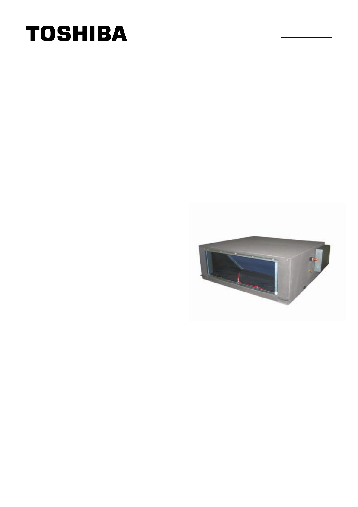
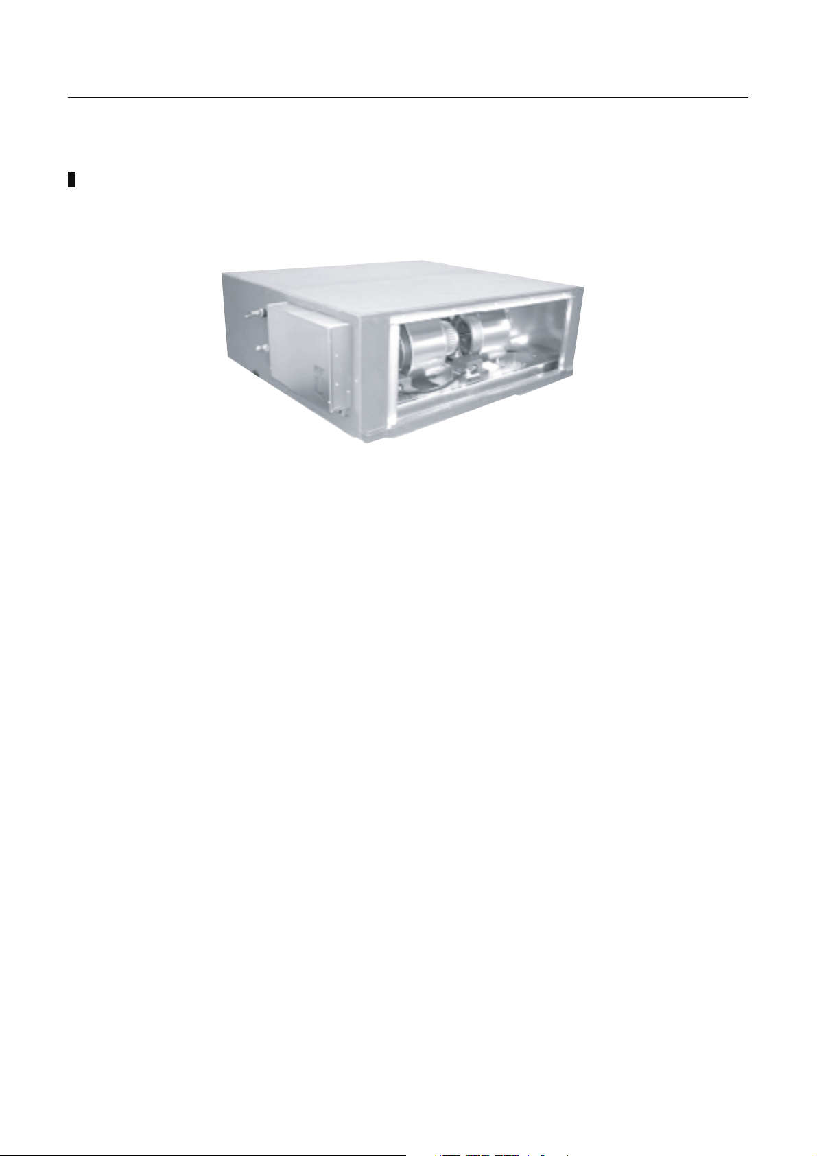
1. Outline of fresh air intake unit
• Type: Concealed Duct High Static Pressure type
Three models (5HP, 8HP, 10HP) are prepared.
• Connectable outdoor unit
Three series (MMY-MAPXXXXT8, MAPXXXXHT8, MAPXXXXHT7) of Cooling/Heating selecting
Super module multi type outdoor unit.
• Corresponding system
Corresponds to a system in which there are the fresh air intake units and the indoor air
conditioners.
(For the fresh air intake units, up to 2 units for one system and also within 30% to capacity of the
connectable indoor air conditioners are allowed.)
• Definition
The fresh air intake unit means an air controller for taken-in fresh air.
Intake of the fresh air often influences on the system so that the normal control of the air conditioner
becomes difficult or gives a large load upon air controller and cooling performance.
Therefore it is frequently adopted to handle the fresh air to a certain condition before the fresh air
will enter in the main air conditioner.
This handling device is called a fresh air intake unit.
NOTE:
The Fresh Air Intake unit is an air conditioner provided to handle the fresh air load and is not to control
the room temperature. For correspondence to the load of the indoor air controller, set an air
conditioner separately.
22
1. System summary
Fresh Air Intake Indoor Unit Type
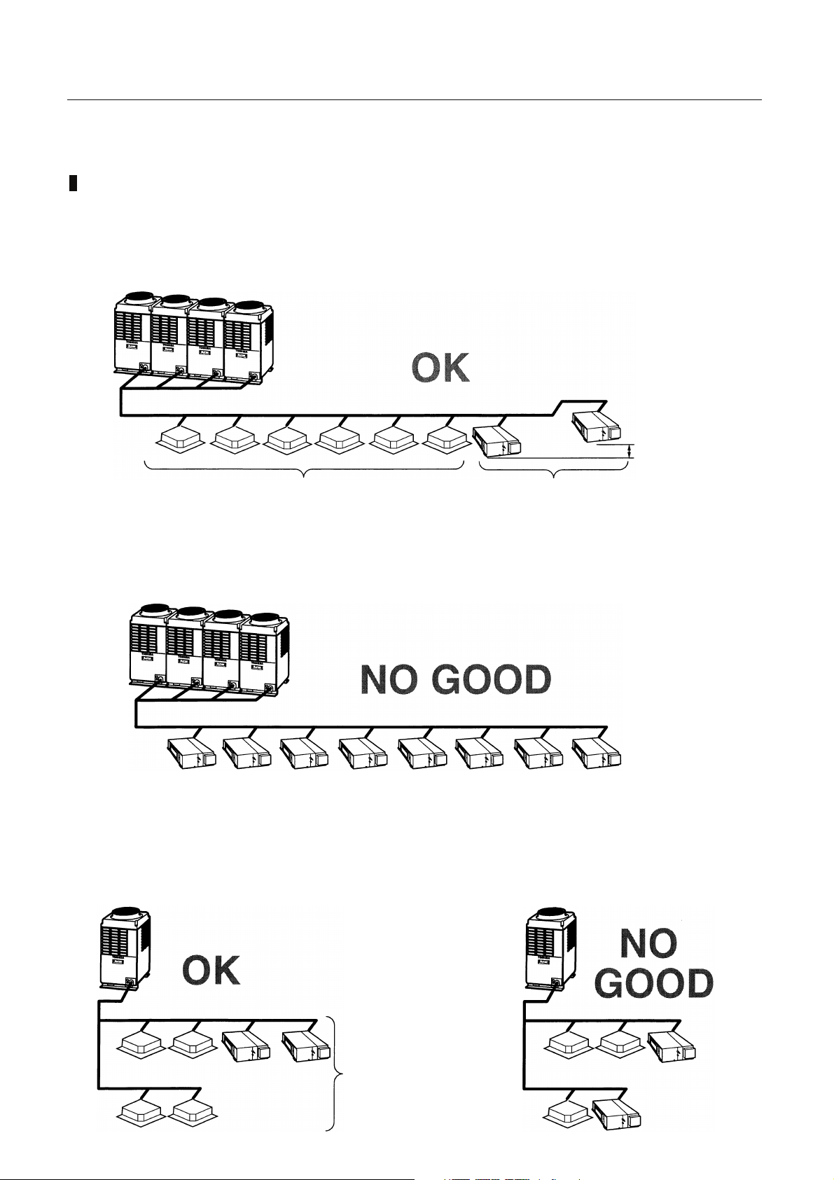
2. System able to be combined
The fresh air intake unit is connectable to S-MMS (Super Modular Multi system).
However this is not connectable to S-HRM (Super Heat Recovery Multi system).
0.5m or less
80 to 100% to capacity of the outdoor
Keep the height difference between the fresh air intake units to 0.5m or less.
Up to two fresh air intake
units occupy 30% or less
· The fresh air intake unit is usually used together with the indoor units on one line of the multi system.
The fresh air intake unit only cannot be connected.
· The total capacity of the indoor units and the fresh air intake units is restricted to 80% to 100%
against the capacity of the outdoor units. (This restriction should be strictly kept for correct control
of the refrigerant.)
· Up to two fresh air intake units can be connected on one line of the multi system.
The allowable total capacity of the two fresh air intake units shall be 30% or less against the total
capacity of the indoor units (including the fresh air intake units).
Connection which stretches
over two floors is unavailable
Height difference:
0.5m or more
33
1. System summary
Fresh Air Intake Indoor Unit Type
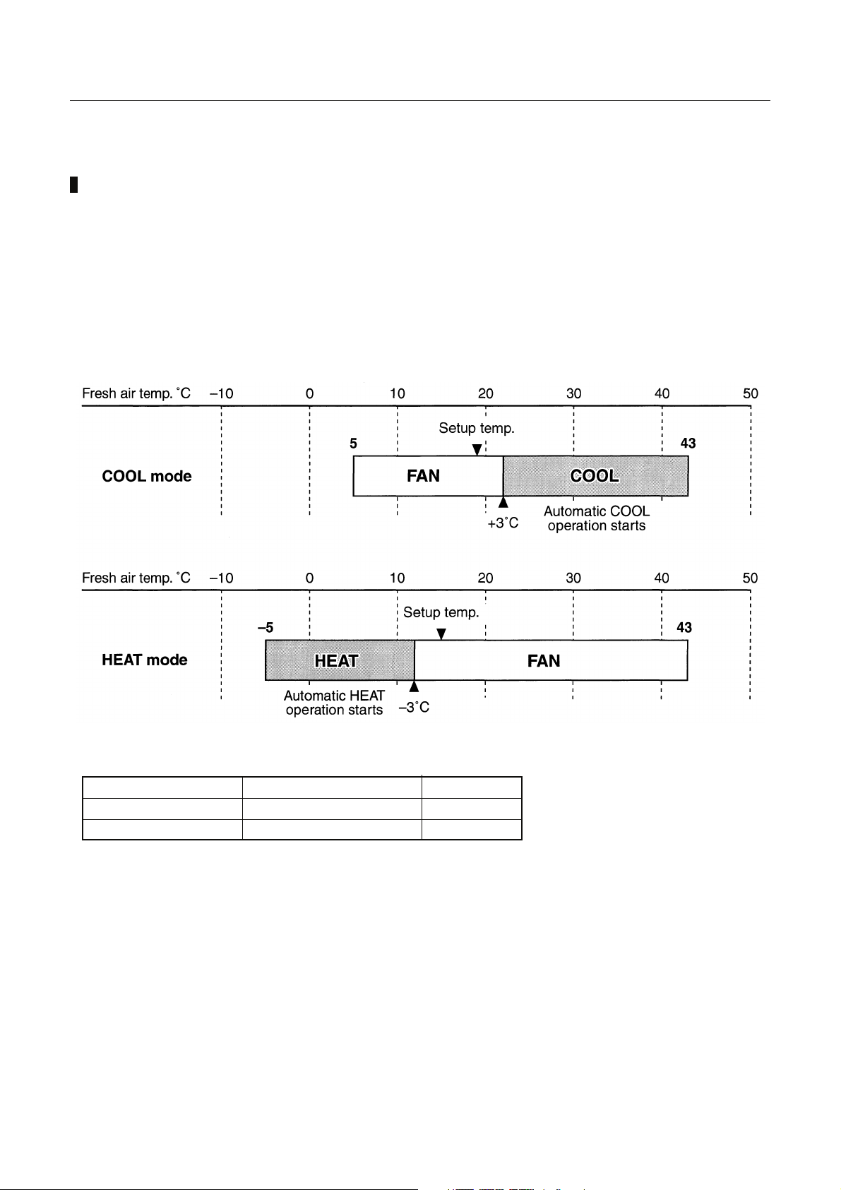
3. Use Conditions
· In COOL mode, if temperature of the fresh air is under the setup temp. +3°C, FAN status is
automatically made. When temperature of the fresh air is under 19°C, FAN status is also made
regardless of the setup temperature.
· In HEAT mode, if temperature of the fresh air is over the setup temp. -3°C, FAN status is
automatically made. When temperature of the fresh air is over 15°C, FAN status is also made
regardless of the setup temperature.
• Operable mode and discharge temp setup range
Operation mode
COOL
HEAT
• Special mentions
1. The fan operation of the Fresh Air Intake unit stops during defrosting.
However the fan operation is enabled to continue by selection.
2. When a central controller is used, divide zone setup of indoor air conditioner and fresh air intake
unit.
3. The standard is to control the discharge temperature. However the priority is given to the capacity
control for the indoor air conditioner in a system in which the normal indoor air conditioner
concurrently operated.
4. The fresh air intake unit cannot be connected with remote controller group of the indoor air
conditioner.
5. In heating operation, if the temperature is below –5°C, the operation stops automatically. (FAN stop)
(To protect the refrigerant cycle)
6. In cooling operation, if the temperature is below 5°C, the operation stops automatically. (FAN stop)
At shipment from factory Setup range
18°C 16 to 27°C
25°C 16 to 27°C
44
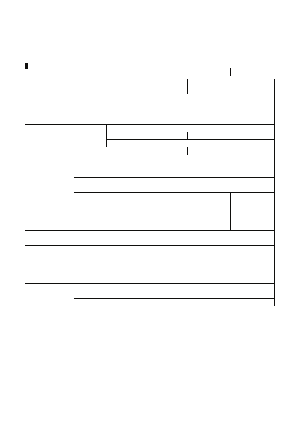
2. Specifications
Fresh Air Intake Indoor Unit Type
50Hz
Model name
Cooling/Heating capacity (Note 1) (kW)
Electical
characteristics
Outer
dimension
Total weight
Heat exchanger
Soundproof / Heat-insulating material
Fan unit
Air filter
Controller
Connecting pipe
Sound pressure level (Note 2) (dB(A))
(High/Med./Low)
Sound power level (High/Med./Low) (dB(A))
Operation range
Power supply
Running current (A)
Power consumption (kW)
Starting current (A)
Main unit Height (mm)
Width (mm)
Depth (mm)
Main unit (kg)
Fan
Standard air flow (m3/h)
Motor (W)
External static pressure
(factory setting)
External static pressure
Air flow limit (m3/h)
Lower limit/Upper limit
Gas pipe (mm)
Liquid pipe (mm)
Drain pipe
Cooling (Note 3) (°C)
Heating (Note 4) (°C)
MMD-AP0481HFE MMD-AP0721HFE MMD-AP0961HFE
14.0/8.9 22.4/13.9 28.0/17.4
1 phase 50Hz 230V (220-240V)
1.43 2.52 2.73
0.28 0.45 0.52
3.50 7.00 7.00
492
892 1,392
1,262
93 144
Finned tube
Non-flammable insulation
Centrifugal fan
1,080 1,680 2,100
160 160 x 2
210 165 190
170-210-230 140-165-180 160-190-205
756 1,176 1,470
Option or field supply
Wired remote controller
15.9 22.2
9.5 12.7
R1
45/43/41 46/45/44
65/63/61 66/65/64
5 - 43
-5 - 43
* The setting temperature is 16 - 27°C(standard FCU…18 - 29°C).
* An option humidifier is not available with Fresh Air Intake Indoor unit.
* Height difference between Fresh Air Intake Indoor units must be within 0.5m.
Height difference between Fresh Air Intake Indoor unit and standard FCU must be within 30m.
Note 1: Rated conditions Cooling : Outdoor air temperature 33°C DB/28°C WB setting temperature 18°C
Heating : Outdoor air temperature 0°C DB/-2.9°C WB setting temperature 18°C
Piping : Length 7.5m / Height 0m
Note 2: The sound level are measured in an anechoic chamber in accordance with JIS B8616. Normally, the
values meausured in the actual operating environment become large than the indicated values due to
the effects of external sound.
Note 3: * When supply air temperature is “setting temperature + 3°C” or less, Fresh Air Intake unit operates as
FAN mode.
* When supply air temperature is 19°C or less, Fresh Air Intake Indoor unit operates as FAN mode.
Note 4: * When supply air temperature is “setting temperature - 3°C” or over, Fresh Air Intake unit operates as
FAN mode.
55
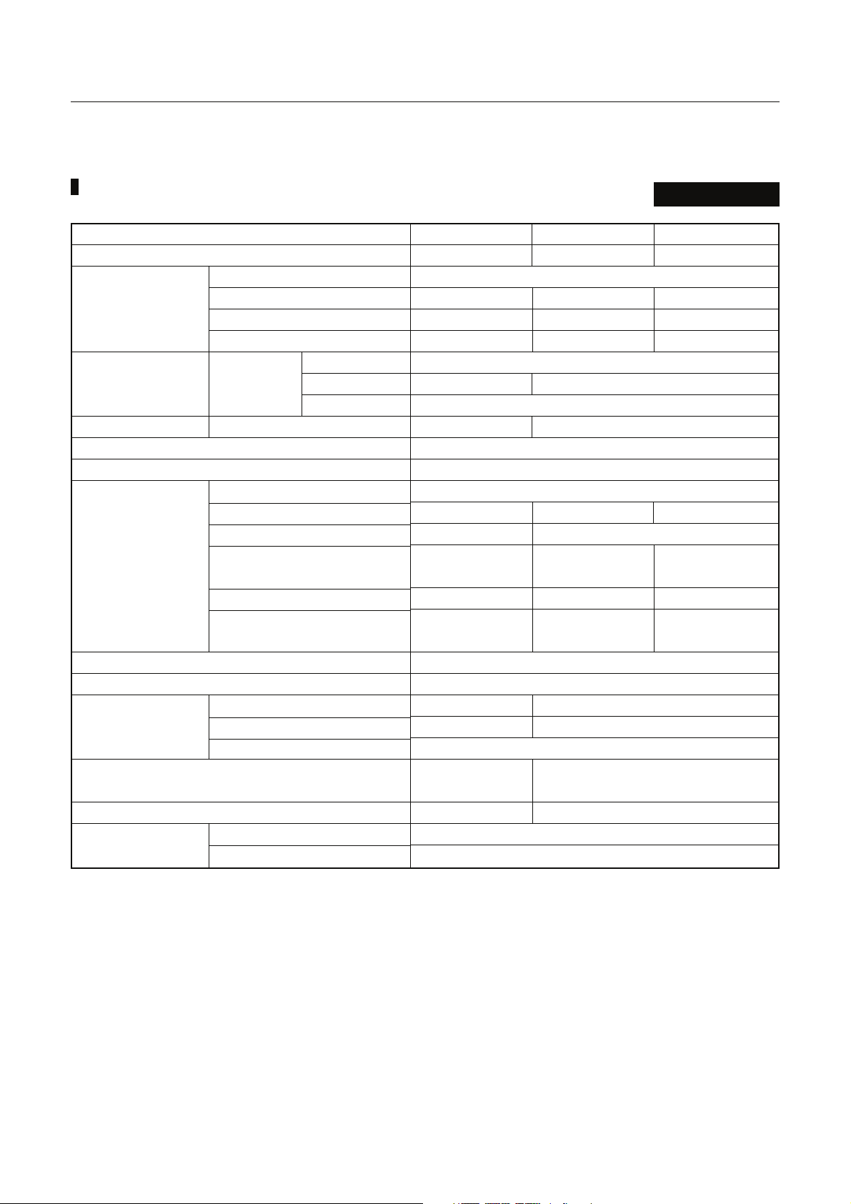
2. Specifications
Fresh Air Intake Indoor Unit Type
Model name
Cooling/Heating capacity (Note 1) (kW)
Electical
characteristics
Outer
dimension
dimension
Total weight
Heat exchanger
Soundproof / Heat-insulating material
Fan unit
Air filter
Controller
Connecting pipe
Sound pressure level (Note 2) (dB(A))
(High/Med./Low)
Sound power level (High/Med./Low) (dB(A))
Operation range
Power supply
Running current (A)
Power consumption (kW)
Starting current (A)
Main unit
Main unit (kg)
Fan
Standard air flow (m3/h)
Motor (W)
External static pressure
(factory setting)
External static pressure
Air flow limit (m3/h)
Lower limit/Upper limit
Gas pipe (mm)
Liquid pipe (mm)
Drain pipe
Cooling (Note 3) (°C)
Heating (Note 4) (°C)
Height (mm)
Width (mm)
Depth (mm)
60Hz
MMD-AP0481HFE MMD-AP0721HFE MMD-AP0961HFE
14.0/8.9 22.4/13.9 28.0/17.4
1 phase 60Hz 220V
1.66 2.75 3.12
0.34 0.55 0.65
3.40 6.80 6.80
492
892 1,392
1,262
93 144
Finned tube
Non-flammable insulation
Centrifugal fan
1,080 1,680 2,100
160 160 x 2
215 210 180
115-215-260 150-210-235 80-180-220
1,188 1,848 2,310
Option or field supply
Wired remote controller
15.9 22.2
9.5 12.7
R1
45/43/41 46/45/44
65/63/61 66/65/64
5 - 43
-5 - 43
* The setting temperature is 16 - 27°C(standard FCU…18 - 29°C).
* An option humidifier is not available with Fresh Air Intake Indoor unit.
* Height difference between Fresh Air Intake Indoor units must be within 0.5m.
Height difference between Fresh Air Intake Indoor unit and standard FCU must be within 30m.
Note 1: Rated conditions Cooling : Outdoor air temperature 33°C DB/28°C WB setting temperature 18°C
Heating : Outdoor air temperature 0°C DB/-2.9°C WB setting temperature 18°C
Piping : Length 7.5m / Height 0m
Note 2: The sound level are measured in an anechoic chamber in accordance with JIS B8616. Normally, the
values meausured in the actual operating environment become large than the indicated values due to
the effects of external sound.
Note 3: * When supply air temperature is “setting temperature + 3°C” or less, Fresh Air Intake unit operates as
FAN mode.
* When supply air temperature is 19°C or less, Fresh Air Intake Indoor unit operates as FAN mode.
Note 4: * When supply air temperature is “setting temperature - 3°C” or over, Fresh Air Intake unit operates as
FAN mode.
66

3. Dimensions
Fresh Air Intake Indoor Unit Type (MMD-AP***HFE)
Service
space
Over 1000
Space necessary for service
Service space
200
Over
Fresh air
intake
unit
200
Check port (600 )
Long hole for M10 hanging bolt
Type
0481
0721, 0961
Hole dia.-Wideth x Length
4- 12 x 40
4- 12 x 92
(185)
30
Drain piping work
example at local site
A
B (Hanging bolt pitch)
(65)
Refrigerative piping work
example at local site
1328
1288 (Hanging bolt pitch)
1262
600
Check port
100
600
X
Filter direction
X
Drain port
(When drain-up kit is mounted)
For vinyl chloride pipes
(Nominal dia 25 : Inner dia 32)
Drain piping work
example at local site
41
37081
C
Blow-off port
Discharge port connecting flange (K)
ED F
Discharge temp sensor
492
360
23
60
61
(Accessory for main unit of product)
38
40638
GHI J
A
Z View
Pre-filter
Refrigerant piping work
example at local site
(205)
(250)
47
Drain port (R1) (Main uint of product)
35
406
51
G IH J
Suction port connecting flange (L)
(Accessory for main unit of product)
X - X detail diagram
Refrigerant pipe
connecting port
(Gas side M)
150
216
850
1262
Suction port
Refrigerant pipe
connecting port
(Liquid pipe N)
704
Electric parts box (With cover)
Filter chamber
High-performance
filter
Pre-filter
Z
292
AP0961HFE
AP0721HFE
AP0481HFE
Model MMD-
1392
1392
892
A
1260
1260
810
250250 250 250 250250250 250 10-M6
215
CB
107.5
D
107.5
E
215
GIJK
F
250250250 250250250
H
250 250
250250
77
10-M6
8-M6
10-M6
10-M6
6-M6
22.2 brazing
22.2 brazing
LM N
12.7 flare
12.7 flare
9.5 flare15.9 flare

r
3. Dimensions
Fresh Air Intake Indoor Unit Type (MMD-AP***HFE)
Work example
Canvas duct
Ceiling
High-performance filter
Over
50
Fresh air
intake unit
Over
Check port
Pre-filter
Air intake duct
100
Filter chamber
Canvas duct
Outside ai
<Installation Notice>
1 The check port should be 600 x 600mm.
2 A slope the piping outside of the unit downward at 1/100.
Be sure to do heat insulating to the connecting peat with the indoor unit. In complete heat insulating may cause
dewing.
3 Check the water drainage is surely performed at the trial operation.
4 Do not install the air conditioner in a salty place such as seaside area and a place where sulfurous gasgenerated
such as in a spa.
5 Please clean the drain plate before the season of cooling air conditioning.
Water overflows from the drain plate when the drain plate and the drain poart are dirty, and the ceiling might be wet.
6 The air filter is not built into the Fresh Air intake indoor unit.
Please remove the dust that enters from air by installing optional Filter chamber, Pre-filter, and High Efficiency Filter.
If no air filter is installed, dust will collect in the heat exchanger, which may cause the air conditioner to fail or to leak.
(local prpcure)
7 Place where the unit cane installed horizontally.
8 Set the canvas duct at air inlet port and air supply port. It is to avoid conveyance of vibration, abnormal resonance
sound and also to make easy the disassembly of the main unit in service time.
9 Be sure to connect the wire and connection cable while matching the terminal.
Please refer to the wiring diagram for details.
10 Please note that the size is different because of MMD-AP0481HFE and MMD-AP0721HFE/MMD-AP0961HFE in the
electric part box.
11 The heat insulator is pasted to externals of the main body of the product. (Bottom board thickness : 16mm, other
thickness : 6mm)
12 Be sure to set the duct at air filter with descending inclination because the suction duct of the this unit is exposed to
outdoors and therefore rainwater, leaves and birds are easy to enter in if it is set horizontally.
Attching wire netting and others to end of the suction duct is also recommended.
13 Set the air inlet duct at descending inclination so that water can be drained even if rainwater enters in.
14 The balloon entrance connection flange and the inhalation mouth connection flange are installed in the main body
of the product.
Please use it detaching it when you connect the duct.
Please obtain Filter chamber directly in the main body of the product when you install Filter chamber and obtain
installation Air intake port connecting flange for C side of A.
15 Connect the ducts directly so that the ducts do not weight on the main unit.
Moreover, please do not damage, and do not knock down air supply temperature sensor when you connect the air
supply duct.
16 Be sure to apply heat insulation for the duct to prevent dewing.
Especially, when it is inhaled to heat it, the be dewy on the surface of the outside of the duct because cold air enters.
Please put the heat insulator.
17 When installing the drain pump and filter chamber sold separately, refer to attachment installation manual.
88

3. Dimensions
Fresh Air Intake Indoor Unit Type (MMD-AP***HFE)
Discharge port connecting flange
MMD-AP0481HFE MMD-AP0721HFE, AP0961HFE
12
65
775
215 215215
65
25
65
12
250
1130
250250250
65
25
394
370
12
25
8- 8
725
344
25
25
Suction port connecting flange
MMD-AP0481HFE MMD-AP0721HFE, AP0961HFE
65
25 25 25
430
12 406 12
630
250 250
2525
580
380
6- 8
NOTE 1)
The left figure shows MMD-AP0721HFE / AP0961HFE.
For MMD-AP0481HFE, one fan motor and one fan are provided.
65
394
430
370
12
406 12
12
25
10- 8
65
250 250 250 250
1080
10- 8
1080
25
344
1130
65
25 25
25
380
25
99

4. Center of gravity
p
Fresh Air Intake Indoor Unit Type
Model name MMD-
AP0481HFE
AP0721HFE
AP0961HFE
Y
X (mm) Y (mm) Z (mm) Weight (kg)
670 480 220 93
670 770 220 144
X
Electric
arts box
Z
1010

5. Electrical current characteristics
Fresh Air Intake Indoor Unit Type
Model name
S-MMS(50Hz)
S-MMS(60Hz)
Model name
MMD-AP0481HFE
MMD-AP0721HFE
MMD-AP0961HFE
MMD-AP0481HFE
MMD-AP0721HFE
MMD-AP0961HFE
Nominal Voltag e
(V-Ph-Hz)
230-1-50
220-1-60
Voltage Range Fan Motor Power supply
Min. Max. kW FLA MCA MOCP
198 264 0.16 0.28 0.35 15
198 264 0.16 x 2 0.45 0.56 15
198 264 0.16 x 2 0.52 0.65 15
198 264 0.16 0.34 0.43 15
198 264 0.16 x 2 0.55 0.69 15
198 264 0.16 x 2 0.65 0.81 15
1111

6. Wiring diagrams
Fresh Air Intake Indoor Unit Type (5HP)
MMD-AP0481HFE
PMV
2
5
3
6
4
1
2
5
3
6
4
1
EXCT
FILTER
3
2
2
2
1
1
1
(WHI)
CN080
(GRN)
CN073
(RED)
CN070
CN081
MCC-1403
FS
for Indoor Unit
Control P.C. Board
RY001
RY002
RY005
RY006
RY004
P301
CN304(GRY)
CN309
1
3
11
(YEL)
3
(BLK)
3
3
5
6
2
3
1
4
5
6
2
3
5
4
Power
Fuse
1
1
supply
~
250V
CN067(BLK)
T5.0A
33
4
(BLU)
CN082
circuit
CN066(WHI)
1
1
1
CN060(WHI)
(WHI)
CN032
CN061(YEL)
(WHI)
CN075
CN074(WHI)
CN050(WHI)
CN041(BLU)
CN040
(BLU)
CN044(BRW)
2
2
423 56 1 4212356 1 423 56
1
3
1
13245
3
2
1
2
1
12
FAN OPTION
DRIVE
T10
1423 56
3
1
3
1
RC
2
1
OC
EMG
CN02
1423 56
(YEL)
1423 56
BLK
BLK
BLU
BLU
CN01
(WHI)
MCC-1520
1423 56
1423 56
Sub P.C.Board
B
A
U2
U1
Line Filter
TR1
Remote
Controller
Board
AB
Remote
Controller
U2
U1
Unit
Outdoor
TF
TC2 TC1
TCJ
TA
(Option)
DP
RED
LM
DP
2
1
3
1
2
1
2
1
2
1
3
1
CN033
CN068
31
797
FAN
PNL
2
1
2
1
(GRN)
CN103
32
(BRW)
CN100
1
2
1
(BLK)
CN101
2
1
(RED)
CN102
2
1
(YEL)
CN104
3
(RED)
CN030
1 2
(GRN)
3
1
(BLU)
31
3 1
5
CN083(WHI)
BLK
ULL
M
H
RY007
WHI
6
RED
~
T10A, 250V
F1
43F1
RED
3
F3 F4
BLK
ORN
F1 F2
BLU
A
RC
4P
(WHI)
GRY
3 4
4
2134
2
RED
1
WHI
FAN1
GRY
RED
WHI
BLK
2
ORN
1
BLU
FM
4P
(WHI)
GRY
GRY
2134
2134
RED
RED
WHI
WHI
Note
At shipment from factory
G&Y
wiring
Fan moter
Blue(50/60Hz)
Black(50/60Hz)
Orange(50/60Hz)
Terminal block No.
F4
F1(Low static pressure tap)
F2(Intermediate static Pressure tap)
F3(High static pressure tap)
43F1
3
5
YEL
Connector
Closed-end
spark killer
43F1
8
7
WHI
BLU
wiring diagram
Fan motor inside
ORN
BLK
WHI
49F
GRY
RED
ACIN
WHI
RED
protection switch
Motor over heating
COLOR
RED : RED
WHI : WHITE
YEL : YELLOW
BLU : BLUE
IDENTIFICATION
WHI
RED
RED
WHI
3
1
Connector
BLK : BLACK
GRY : GRAY
PNK : PINK
ORN : ORANGE
BRW : BROWN
1212
RED
S(N)
R(L)
Unit
Earth
Indoor
Screw
G&Y : GREEN&YELLOW
50Hz
~
60Hz
~
220V
Power Supply
220-240V
Fan Moter
Parts Name
Running Capacitor
RC
FM
Symbol
number as figure and lead wire's color of fan motor.
exchange the lead wire of arrow( ) position after check the terminal
the froat switch connector to CN030 connector.
Letter at inside indicates the terminal number.
4. When installing the drain pump connect
5. A position is connected to terminal block when change to static pressure.
3. indicates the control P.C board.
2. A dotted line and broken line indicate the wiring at site.
1. indicates the terminal block.
Sold
Separately
Transformer
Temp sensor
Blow temp. sensor
Intake air temp. sensor
Fan Motor Control Relay
007
~
TF
TA
TR1
RY005
TC1,TC2,TCJ
Drain Control Relay
RY002
Drain Pump Motor
Pulse Motor Valve
Fuse for Fan Motor
Fan Motor Control Relay
F1
DP
43F1
PMV
Float Switch
FS

6. Wiring diagrams
Fresh Air Intake Indoor Unit Type (8-10HP)
MMD-AP0721HFE
MMD-AP0961HFE
PMV
2
5
3
1
6
4
2
5
3
1
4
6
EXCT
FILTER
3
(GRN)
CN080
1
CN073
2
(RED)
1
CN070
2
(WHI)
2
1
CN081
MCC-1403
FS
for Indoor Unit
Control P.C. Board
RY001
RY002
RY005
RY006
RY004
P301
CN304(GRY)
CN309
(YEL)
3
1
1
8
8
7
WHI
WHI
5
3
4
(BLK)
Fuse
313
1
3
1
ACIN
RED
6
6
supply
Power
~
250V
T5.0A
3
WHI
5
2
3
1
4
5
2
3
1
4
(BLU)
CN082
3456
2
CN060(WHI)
2
1
FAN OPTION
DRIVE
(WHI)
CN032
3456 1
2
CN061(YEL)
T10
(WHI)
CN075
3456 1
3456
circuit
2
2
1
1
13
13
CN074(WHI)
345
2
CN050(WHI)
31
3
121
CN041(BLU)
RC
2
121
CN040
(BLU)
OC
2
1
EMG
CN044(BRW)
CN066(WHI)
CN067(BLK)
2
1
2
1
CN02
3456
2
1
(YEL)
3456
2
1
MCC-1520
Sub P.C.Board
BLK
BLK
BLU
BLU
Line Filter
CN01
3456
2
1
B
A
U2
U1
(WHI)
3456
2
1
TR1
Remote
Controller
B
Board
A
Remote
Controller
U2
U1
Unit
Outdoor
~
T10A, 250V
F1
RED RED
WHI
RED
RED
WHI
1
3
TF
TC2 TC1
TCJ
TA
(Option)
DP
RED
RED
21
1
3
1
21
21
21
3
LM
CN033
DP
CN068
13
FAN
6
RED
7
PNL
2
1
12
(GRN)
CN103
123
(BRW)
CN100
12
(BLK)
CN101
12
(RED)
CN102
12
(YEL)
CN104
(RED)
CN030
123
(GRN)
13
(BLU)
13
UL
15
L
HM
7
93
RY007
CN083(WHI)
BLK
spark killerspark killer
43F243F1
7
7
6
6
RED
~
T10A, 250V
F2
RED
8
RED
RED
ORN
43F1
ORN
43F2
5
WHI
4
4
43F1
Unit
Indoor
WHI
3
5
Earth
Screw
BLU ORN BLK
FAN1
(WHI)
4321
RED
WHI GRY
F1 F2 F3 F4
BLU ORN BLK
A
FAN2
(BLU)
4321
GRY
RED
WHI
Connector
Closed-end
50Hz
~
60Hz
~
220V
Power Supply
220-240V
123
BLU ORN BLK
4P
(WHI)
4321
4321
GRY
RED
RED
WHI
WHI GRY
123
BLU ORN BLK
4P
(WHI)
4321
4321
GRY
GRY
RED
RED
WHI
WHI
F1 F2 F3 F4
A
RC1
4P
4321
GRY
RED
WHI
RC2
4P
4321
GRY
RED
WHI
YEL
S(N)
R(L)
Note
FM1
G&Y
FM2
G&Y
wiring
Fan moter
Blue(50/60Hz)
At shipment from factory
Black(50/60Hz)
Orange(50/60Hz)
Terminal block No.
F4
F1(Low static pressure tap)
F2(Intermediate static Pressure tap)
F3(High static pressure tap)
number as figure and lead wire's color of fan motor.
exchange the lead wire of arrow( ) position after check the terminal
the froat switch connector to CN030 connector.
Letter at inside indicates the terminal number.
4. When installing the drain pump connect
5. A position is connected to terminal block when change to static pressure.
3. indicates the control P.C board.
2. A dotted line and broken line indicate the wiring at site.
1. indicates the terminal block.
BLU
wiring diagram
Fan motor inside
ORN
BLK
WHI
GRY
49F
RED
protection switch
Motor over heating
COLOR
RED : RED
WHI : WHITE
YEL : YELLOW
BLU : BLUE
IDENTIFICATION
Connector
BLK : BLACK
GRY : GRAY
PNK : PINK
ORN : ORANGE
BRW : BROWN
1313
G&Y : GREEN&YELLOW
Fan Moter
Parts Name
Running Capacitor
FM1 2
RC1 2
Symbol
Transformer
Temp sensor
Blow temp. sensor
Intake air temp. sensor
Fan Motor Control Relay
007
~
TF
TA
TR1
RY005
TC1,TC2,TCJ
Sold
Drain Pump Motor
Pulse Motor Valve
Fuse for Fan Motor
Drain Control Relay
Fan Motor Control Relay
DP
F1 2
PMV
RY002
43F1 2
Separately
Float Switch
FS

7. Fan characteristics
Fresh Air Intake Indoor Unit Type
<220V>
50Hz
MMD-AP0481HFE (5HP)
Standard air volume: 1080m3/h
2.0
High static pressure tap
1.5
1.0
Mid static pressure tap
Low static pressure tap
High static pressure tap
Low static pressure tap
Fan motor current (A)External static pressure (Pa)
0.5
350
300
250
200
Mid static pressure tap
150
100
50
MMD-AP0721HFE (8HP)
Standard air volume: 1680m3/h
3.0
High static pressure tap
2.5
Fan motor current (A)External static pressure (Pa)
2.0
1.5
350
300
High static pressure tap
250
200
150
Low static pressure tap
100
50
Low static
pressure tap
Mid static
pressure tap
Mid static pressure tap
0
Air volume (m3/h)
MMD-AP0961HFE (10HP)
Standard air volume: 2100m3/h
Fan motor current (A)External static pressure (Pa)
3.5
Mid static pressure tap
3.0
2.5
2.0
350
300
250
200
150
Mid static pressure tap
100
High static pressure tap
High static pressure tap
Low static pressure tap
Low static
pressure tap
120011001000900800
0
1800160014001200
Air volume (m3/h)
50
0
Air volume (m3/h)
23002100190017001500
1414

7. Fan characteristics
Fresh Air Intake Indoor Unit Type
<220V>
60Hz
MMD-AP0481HFE (5HP)
Standard air volume: 1080m3/h
2.0
High static pressure tap
1.5
M
Fan motor current (A)External static pressure (Pa)
id static pressure
1.0
0.5
350
300
250
200
150
Low static pressure tap
100
50
tap
Low static pressure tap
High static pressure tap
Mid static
pressure tap
MMD-AP0721HFE (8HP)
Standard air volume: 1680m3/h
3.0
High static pressure tap
2.5
Mid static pressure tap
2.0
Low static pressure tap
High static pressure tap
Fan motor current (A)External static pressure (Pa)
1.5
350
300
250
200
Mid static
pressure tap
150
Low static pressure tap
100
50
0
Air volume (m3/h)
MMD-AP0961HFE (10HP)
Standard air volume: 2100m3/h
3.5
High static pressure tap
3.0
Fan motor current (A)External static pressure (Pa)
2.5
Low static pressure tap
2.0
350
300
250
200
150
Low static
pressure tap
100
Mid static pressure tap
High static
pressure tap
Mid static
pressure tap
120011001000900800
0
1800160014001200
Air volume (m3/h)
50
0
Air volume (m3/h)
23002100190017001500
1515

7. Fan characteristics
Fresh Air Intake Indoor Unit Type
<230V>
50Hz
MMD-AP0481HFE (5HP)
Standard air volume: 1080m3/h
2.0
High static pressure tap
1.5
1.0
Mid static pressure tap
Low static pressure tap
Low static pressure tap
Fan motor current (A)External static pressure (Pa)
0.5
350
High static pressure tap
300
250
200
Mid static pressure tap
150
100
50
MMD-AP0721HFE (8HP)
Standard air volume: 1680m3/h
3.0
High static pressure tap
2.5
Fan motor current (A)External static pressure (Pa)
2.0
1.5
350
300
High static pressure tap
250
200
150
Low static pressure tap
100
50
Low static
pressure tap
Mid static
pressure tap
Mid static pressure tap
0
Air volume (m3/h)
MMD-AP0961HFE (10HP)
Standard air volume: 2100m3/h
Fan motor current (A)External static pressure (Pa)
3.5
Mid static pressure tap
3.0
2.5
2.0
350
300
250
200
Mid static pressure tap
150
100
High static pressure tap
High static pressure tap
Low static pressure tap
Low static
pressure tap
120011001000900800
0
1800160014001200
Air volume (m3/h)
50
0
Air volume (m3/h)
23002100190017001500
1616

7. Fan characteristics
Fresh Air Intake Indoor Unit Type
<240V>
50Hz
MMD-AP0481HFE (5HP)
Standard air volume: 1080m3/h
2.0
High static pressure tap
1.5
1.0
Fan motor current (A)External static pressure (Pa)
Mid static pressure tap
0.5
350
High static pressure tap
300
250
200
Low static pressure tap
150
100
50
Low static pressure tap
Mid static pressure tap
MMD-AP0721HFE (8HP)
Standard air volume: 1680m3/h
3.0
High static pressure tap
2.5
Mid static pressure tap
2.0
Low static pressure tap
1.5
Fan motor current (A)External static pressure (Pa)
350
300
High static pressure tap
250
Mid static pressure tap
200
150
Low static pressure tap
100
50
0
Air volume (m3/h)
MMD-AP0961HFE (10HP)
Standard air volume: 2100m3/h
Fan motor current (A)External static pressure (Pa)
3.5
Mid static pressure tap
3.0
2.5
2.0
350
300
250
200
150
100
High static pressure tap
Low static pressure tap
High static pressure tap
Mid static
pressure tap
Low static
pressure tap
120011001000900800
0
1800160014001200
Air volume (m3/h)
50
0
Air volume (m3/h)
23002100190017001500
1717

8. Sound characteristics (NC Curve)
Fresh Air Intake Indoor Unit Type
Measureing
Center
1.5m
MMD-AP0721HFE
MMD-AP0961HFE
Microphon
MMD-AP0481HFE
Fan tap
Sound pressure
level (dB(A))
Octave band sound pressure (dB)
Audibility limits of
continuous white
HML
45 43 41
Fan tap
Sound pressure
level (dB(A))
Octave band sound pressure (dB)
Audibility limits of
continuous white
HML
46 45 44
Octave band center frequency (Hz)
Octave band center frequency (Hz)
1818

Fresh Air Intake Indoor Unit Type
Engineering Data
May, 2007 First Edition
 Loading...