

Toshiba MMD-AP0304H2UL, MMD-AP0484H2UL, MMD-AP0364H2UL, MMD-AP 4H2UL Series, MMD-AP0724H2UL MMD-AP0964H2UL Wiring Diagram
MMD-AP___4H2ULE15-3H1
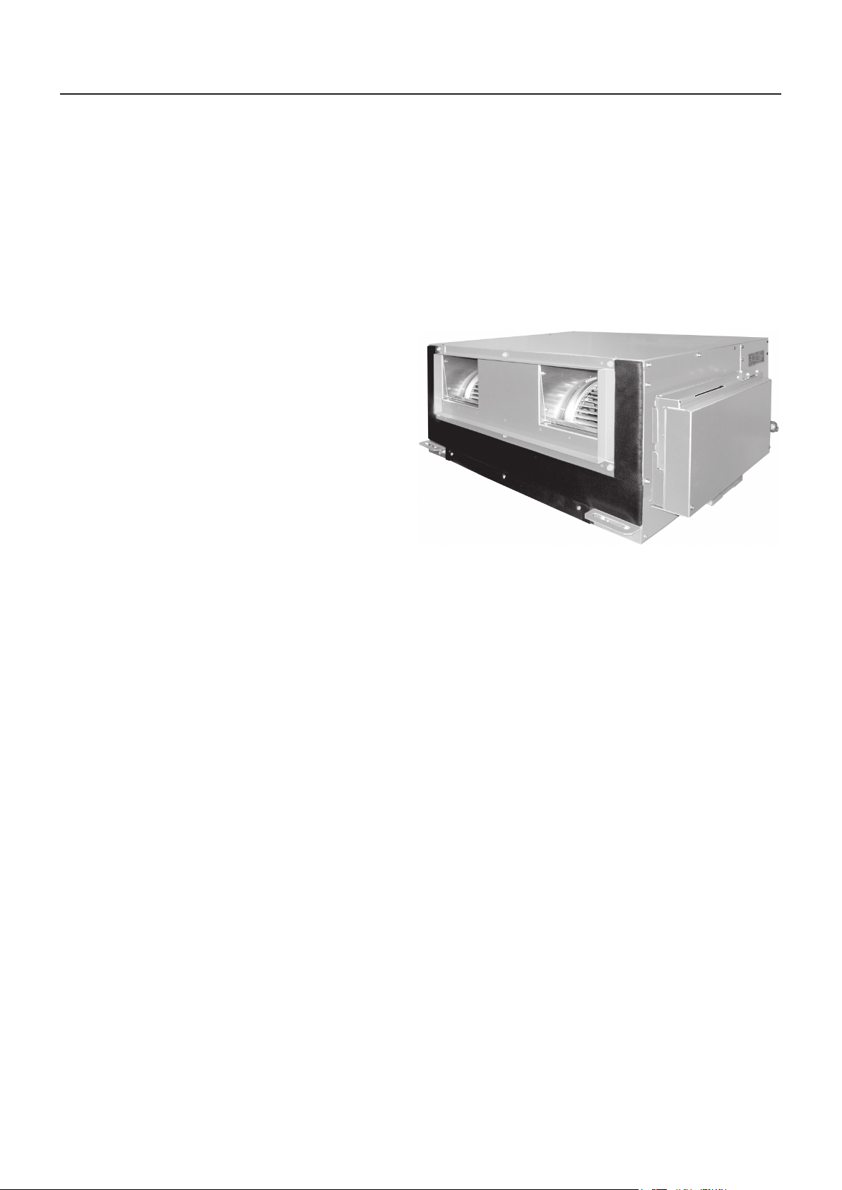
High Static Ducted type
MMD-AP0304H2UL
MMD-AP0364H2UL
MMD-AP0484H2UL
MMD-AP0724H2UL
MMD-AP0964H2UL
Contents
1. Specifications
2. Dimensions
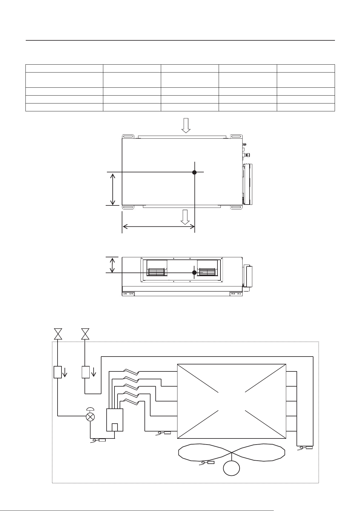
3. Center of gravity
4. Piping diagram
5. Wiring diagram
6. Electrical current characteristics
7. Sensible capacity table
8. Fan characteristics
9. Sound data
1
MMD-AP___4H2UL E15-3H1
1. Specifications
Concealed Duct High Static Pressure type
Model name MMD- AP0304H2UL AP0364H2UL AP0484H2UL AP0724H2UL AP0964H2UL
Cooling Capacity
Heating Capacity
kBtu/h
kBtu/h
30 36 48 72 81
34 40 54 96 108
Electrical
characteristics
Appearance Zinc hot dipping steel plate
Dimension
Total weight
Heat exchanger Finned tube
Fan unit
Air filter Field supply
Power supply 230 V (208/230 V) 1phase 60 Hz
Power consumption (208/230 V) kW 0.38/0.41 0.38/0.41 0.35/0.41 1.37/1.44 1.20/1.63
Height In 15.0 18.5
Unit
Packing
Unit lbs 128 154 362
Packed unit lbs 141 176 417
Fan Centrifugal fan
Standard air flow cfm 926 1235 2120 2473
Motor W 260 370 × 3
External
static
pressur
e (*1)
Air flow
limit
Width In 33.5 47.2 54.3
Depth In 26.0 49.2
Height In 17.0 24
Width In 42.6 56.4 61.8
Depth In 31.9 55.3
Factory default (208/230 V)
208 V (High tap/Mid tap/Low tap)
(*3)
230 V (High tap/Mid tap/Low tap)
(*3)
Lower limit cfm 755.2 988.2 1766 2473
Upper limit cfm 1132.8 1447.1 2002 2944
In
WG
In
WG
In
WG
0.641/0.814 0.296/0.519 0.580/0.929 0.317/0.734
1.075 - 0.641 - 0.287
1.175 - 0.814 - 0.506
0.606 - 0.296 - Non
0.801 - 0.519 - 0.114 1.12 - 0.929 - 0.29 1.099 - 0.734 - 0.459
0.896 - 0.580 - 0.346 0.739 - 0.317 - 0.062
Gas side In 5/8" 7/8"
Connecting
pipe
Sound pressure level
(*2)
Liquid side In 3/8" 1/2"
Drain port (Nominal dia.) In VP25 (Polyvinyl chloride tube: External Dia.1-1/4 Internal Dia.1)
208 V (High tap/Mid tap/Low tap)
(*3)
230 V (High tap/Mid tap/Low tap)
(*3)
dB(A) 49.5/45/41 47/44/- 49.5/45/41
dB(A) 51/47/43 49/46/43 51/47/43
Note
(*1) Non attached filter
(*2) The actual values in an external operating environment are generally higher than the indicated values due to the contribution from ambient
noise.
(*3) The tap is set by wire connection change of fan motor.
2
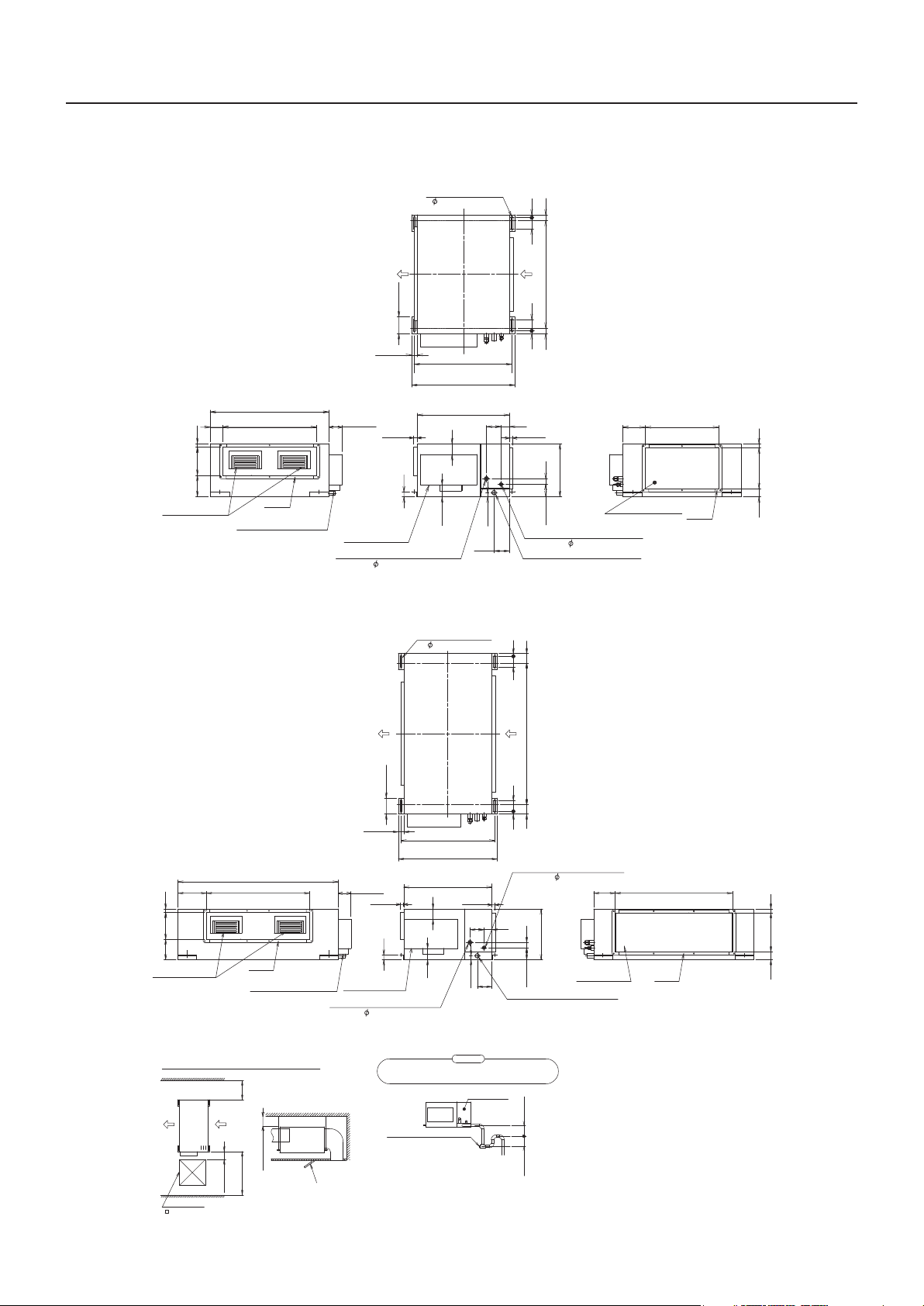
2. Dimensions
MMD-AP0304H2UL, AP0364H2UL
Ho
4- 0.5"(12)x3.6"(92)
4.7"(120)
MMD-AP___4H2ULE15-3H1
l
e
o
for
g
lt
ingb
han
0.8"(20)
3.1"(80)3.1"(80)0.8"(20)
31.5"(800)
(Hanging bolt mountingpitch)
Unit external dimension
3.4"
(87) 26.5"(672)
8"(202) 1"(25)
6"
(154)
Air disc harge port
MMD-AP0484H2UL
33.5"(850)
Flange
Entering of power supply
and communica tion wires
1.6"(40)
(Hanging bolt mou ntin
Unit externaldimensio
3.8"(96)
1"(25)
1.4"(35)
Electrical
control box
Refriger ant pipe connecting port
(Gas s
ide 5/8"(15.
4.7"(120)
9))
Hole for hanging bolt
4-0.5"(12)x3.6"(92)
27.6"(700)
29.1"(740)
26"(660)
2.9"
(73)
3.4"(87)
g
4.1"(105)
1.2"(30)
4.3"
(110)
pitch
1"(25) 1"(25)
)
n
2.4"(60)
1"(25)
1.6"(40)
15"(380)
3.5"(90)
Refrigerant pipe connecting port
(Liquid side 3/8"(9.5))
Drainpipeconnecting port(VP25)
(Male screw)
2.8"(70)
3.1"(80) 0.8"(20)
41.7"(1060)
(Hanging bolt mounting pitch)
3.1"(80)0.8"(20)
.
6
4"
(163)
Air suction port
20.7"(526)
Flange
1.2"
2.3"
(59) 11.5"(292) (30)
Unitexternal dimensio
8.3"(212)
8"(202) 1"(25)
6"
(154)
Airdischargepo
Space required for installationor service work
Checkport
23.6"(600
47.2"(1200)
rt
19.7"
(500)
31.5"(800)
7.9"(200)
)
n
30.4"(772)
Flange
Enteringofpower supply
andcommunication wires
e
Servic
space
or more
Distance from building
or more
5.9"(150)
Service
or more
s
e
pac
1.6"(40
3.8"(96
(25
1"
Electrical
control box
Refrigerant pipeconnecting port
(Gassi
de 5/8"(15.9
t
Checkpor
)
27.6"(700)
(Hangingbolt mounting pitc
29.1"(7
Unit external dimensio
)
))
ca
usegarbagei
Plug
3.4"
2.9"
(87)
26"(660)
(73)
lug
ndrai
andto
)
1.4"(35)
Besuretoset the p
be
(Check and cleaningport
40)
n
1"(25)
4.1"
(105)
4.3"
(110)
1.2"(30)
n
n
Atte
io
t
eittobeableto cleaning,
mak
n
piles
piping
Checkpanel
)
3
2.8"(70)
)
h
ant
R
pipeconnectin
efriger
dside
(Liqui
3/8"(9.5))
2.4"
(60)
1.6"(40)3.5"(90)
15"(380)
Drain pipe connecting port(VP25)
(
screw)
Male
intr
n
ap
dr
upeasily
.
a
i
or more
3.9"(100)
or more
2"(50)
g
ort
p
.4
6
"
(163)
rt
Air suction p
o
<Note>
1. Indoor unit does not have air filter its inside.
So be sure to set an air filter (local
arrangements) in the position maintained
easily such as a air intake grille.
(If there is no air filter, dusts are blocked in the
air heat exchanger and it may cause failure or
water leak in air-conditioner.)
2. Leave sufficient space to remove the air filter
when you attach it.
4.5
3
Flange
"
(876)
1.2"
2.3"
(59) 11.5"(292) (30)
MMD-AP___4H2UL E15-3H1
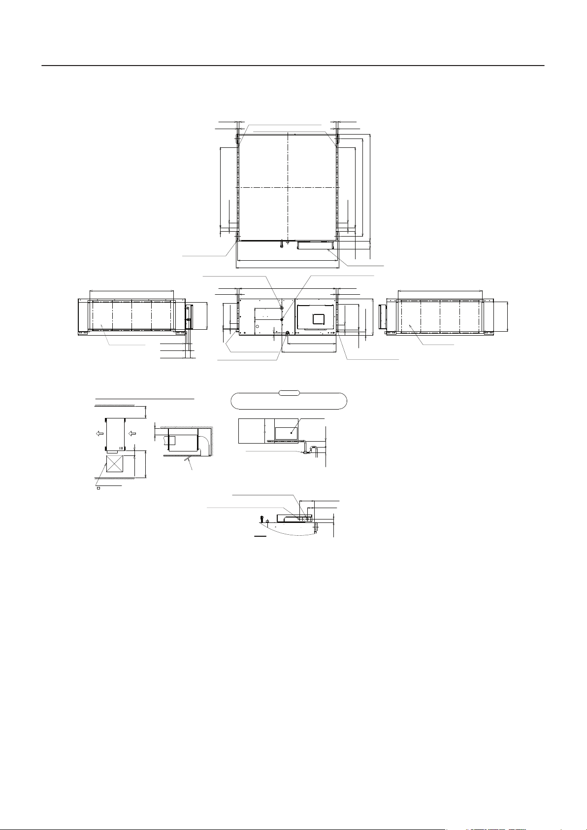
MMD-AP0724H2UL, MMD-AP0964H2UL
Hole for hanging bolt
(4-Ø1/2"(12)×3.6"(92))
42.6"(1083) Outside
7.9"
7.9"(200)
Service
space
(200)
or more
5.9"(150)
Service
or more
space
39.4"(1000)
or more
0.9"(22)
1.8"(46)
2.6"(65)
Distance from building
Check port
Air discharge port
Space required for installation or service work
Check port
23.6"(600)
1"(25) 1"(25)
0.6"(15)
2.6"(65)
1.8"(45) 2.6"×16=40.9"(65×16=1040)
Refrigerant pipe connecting port
(Gas side Ø7/8"(22.2) Brazed)
0.6"(15)
2.6"(65)
Outside
13.7"(347)
(65×5=325)
2.6"×5=12.8"
Screw hole for duct mounting
0.4"(9.5)
(6-M5)
Drain pipe connecting port(V25)
Taper screw for R1,1"(25.4) pipes
Be sure to set the plug and to make it to be able to cleaning,
because garbage in drain piping piles up easily in drain trap.
Ø1"(26) Hole for control wire
Ø7/8"(22.2) Hole for power supply cable
Screw hole for duct mounting(17-M5)
Screw hole for duct mounting(17-M5)
50.7"(1288) Hanging bolt mounting pitch
52.3"(1328)
49.2"(1250)
5.9"
(150)
7.9"
(200)
(31)
1.2"
27.5"(698)
Attention
Plug
(Check and cleaning port)
and remote control wiring
0.6"(15)
Refrigerant pipe connecting port
(Liquid side Ø1/2"(12.7) Flared)
24.6"(624)
Check panel
7.8"(198.5)
3.6"(91.5)
3.9"(100)
or more
2"(50)
or more
1"(25)1"(25)
0.6"(15)
2.6"(65)
54.3"(1380)
2.6"×16=40.9"(65×16=1040)
2.6"(65)
49.6"(1260) Hanging bolt mounting pitch
3.9"
(45)
1.8"
(100)
Electric parts box
1.8"(45)
(65×5=325)
18.5"(470)
2.6"×5=12.8"
1"(25)
Screw hole for duct mounting
(6-M5)
<Note>
1. Indoor unit does not have air filter its inside.
So be sure to set an air filter (local
arrangements) in the position maintained
easily such as a suction grills.
(If there is no air filter, dusts are blocked in the
air heat exchanger and it may cause failure or
water leak in air-conditioner.)
2. Leave sufficient space to remove the air filter
when you attach it.
Unit: in (mm)
42.6"(1083) Outside
Air suction port
Outside
15.1"(383)
Z view
(42)
1.7"
4
MMD-AP___4H2ULE15-3H1
㼅
㼄
㻳
㼆
㻳
Air heat exchanger
at indoor side
Sensor
(TC2)
㹋
Fan
Fan Motor
Sensor
(TCJ)
Sensor
(TC1)
Strainer
Pulse
Motor
Valve
Liquid side
Gas side
Capillary Tube
Sensor
(TA)
3. Center of gravity
Model name X (In) Y (In) Z (In) Total weight (lbs)
MMD-AP0304H2UL
MMD-AP0364H2UL
MMD-AP0484H2UL 11.4 25.4 7.7 154
MMD-AP0724H2UL 11.4 28.4 8.7 362
MMD-AP0964H2UL 11.4 28.4 8.7 362
11.4 17.7 7.7 128
Air intake
4. Piping diagram
Air discharge
5

MMD-AP___4H2UL E15-3H1
5. Wiring diagram
MMD-AP0304H2UL, AP0364H2UL, AP0484H2UL
e
J
A
T
TC
°
°
t
2
121
)
4
)
2
D
0
L
0
1
1
E
N
(RE
(Y
C
CN
)
3
D
E
N30
1
C
(R
)
33
RN
N
G
C
(
)
8
6
LU
(B
CN
3 1 3
1
V
M
P
M
r
e
ill
ark k
Sp
)
6
U
L
5
B
(
6
82
3
N
2 4
C
1
1
5 3
7
9
I)
3
8
H
007
N
Y
W
(
C
R
)
Y
(GR
301
P
K
L
B
CN304
D
RE
I
WH
7
3F1
4
8
1
2
C
C
T
T
L
°
t
t°t
2
1
)
01
K
1
L
N
(B
C
1
0
0
Y
R
002
Y
R
006
Y
R
4
0
0
RY
3
1
N
P
3
1
1
)
)
0
00
8
W
1
RN
N
R
N
G
B
C
(
(
C
RY005
V
A
01
5
0
5
T
F0
2
D
RE
R
T
TE
C
IL
X
F
E
2
123
)
)
0
3
I
D
7
7
H
E
N
N
R
C
C
(W
(
)
K
(CH
71CN72
N
C
for Indoor Unit
Control P.C. Board
)
LK
N66
B
(
C
7
6
1
1
3
N
C
I
WH
)
HI
1354212
)
1
(W
4
K
8
L
CN
(B
)
P
IS
D
(
r
y
l
e
p
w
p
su
Po
3
0
14
C
C
M
HI)
(W
CN40(
2
1
TION
0
3 5 6
6
2
OP
CN
1
)
E
HI
IV
2
(W
2
DR
3
1
N
N
C
A
F
6
L)
54
E
Y
(
3
T10
2
N61
1
C
3
1
I)
74
H
N
C
(W
6
5
t
i
43
u
c
ir
2
c
1
5
I)
7
H
N
W
C
(
I)
H
5
W
(
3
N50
1 24
C
3
1
)
L
E
309
Y
(
CN
)
1
U
4
L
)
N
B
C
(
LU
B
3
K
2
L
1
B
BLK
U BLU
L
B
Line Filter
ur
ess
pr
c
tati
S
tap
0V
3
4
2
048
D-)
P
A
208 V
iring(MM
w
364
V
0
P
A
,
motor
4
n
30
a
208/230
0
F
P
A
l
.
o
mina
N
r
e
T
0
rd
)
I)
2
a
L
6
5
4
3
2
1
6
5
H
E
1
5
Bo
-
Y
W
(
.
(
C
4
C
1
.
3
02
0
MC
2
bP
CN
CN
1
u
S
e
g
lta
vo
w
o
L
BA
U2
U1
TB02
,
208 V
ap
is
ap
et
ap
t
ht
ig
Low
Middl
H
U
BL
1
*
―
N
R
BLK
O
LU
B
F1F3
F2
(Refer to the static pressure specifications for each tap.)
L
2U
H
0484
P
-A
D
source for MM
r
e
pow
f
o
e
g
lta
vo
fa
1I
*
)
p.
x
e
(
N
U
m
R
L
a
r
O
B
diag
g
in
wir
ide
s
n
i
r
(F1).
o
t
o
ap
t
w
se Lo
u
do not
K
L
m
WHI
B
an
F
3
0
TB
F4
F3
F2
F1
BA
U2
U1
RED
I
WH
4
R
T
3F1
4
6
WHI
ED
R
)
ly
ote
em
arate
F01
red R
dsep
Control
l
o
Wi
S
(
RED
r Indoor unit
o
Maybe Outdo or unit
WHI
end
Closed
connector
Flow selector
nit
u
5
,250V
A
T10
screw
Ground
A
RC
1
ED
43F
R
3
TB01
L1 L2
screw
door unit
n
I
Ground
ating
e
witch
h
s
r
n
e
io
v
o
r
tect
to
ro
o
p
M
F
9
4
D
GRY
RE
LK
B
N
R
O
U
L
B
S
M
1
FM
4
GRY
3
2
1
I
WH
0
6
1-
tage
-
l
ower supply
08/230
ld P
High vo
2
Fie
elay
R
EN
NK
RAY
I
Fuse
Fuse
F01
Fan Motor
FM
F001
Motor Con trol
n
Pulse Motor Valve
Running Capacitor
Indoor temp sensor
Fa
TA
RC
PMV
RY005,006,007
Terminal Block
TB01,02,03
Transformer
Temp sensor
TR
indicates the connection terminal.
TC1,TC2,TCJ
indicates the terminal block.
Long dashed short dashed line indicate
the accessories.
1.Broken line indicate the wiring at site.
2.
indicates the control P.C. board.
indicates the connector on the control
indicates the protection ground.
P.C. board.
3.
block when change to static pressure.
exchange the lead wire of arrow( )
position after check the terminal
5. A position is connected to terminal
4.
number as figure and lead wire's color
Connector
Parts Name
Fan motor Control Relay
CN**
43F1
Symbol
TION
G
P
A
FIC
TI
EN
D
I
OR
L
O
C
GRY :
RED : RED
PNK :
E
T
:WHI
I
WH
:GRE
N
BRW : BROWN
GR
ORN : ORANGE
K
C
A
L
YELLOW
B
:
:
BLK
YEL
BLU : BLUE
of fan motor.
6

MMD-AP0724H2UL, MMD-AP0964H2UL
MMD-AP___4H2ULE15-3H1
1
CN101
RY001
RY002
RY006
RY004
CN304
(GRY)
TC2
t°
WHIWHI
2
(BLK)
1
WHI
1
3
TC1
t°
3
2
CN100
(BRW)
RY005
TB03
7
F301
PNL
231
CN80
T5A
250V
CN67
(BLK)
EXCT
211
CN73
CN70
(RED)
(GRN)
(CHK)
CN71
Control P.C. Board
3
1
FILTER
221
5
4
3
CN81
(WHI)
(BLK)
CN32
(DISP)
CN72
Power
circuit
supply
MCC-1403
for Indoor Unit
CN66
CN40
(WHI)
(BLU)
1
2
123
WHI
RED
534 6
122
CN60(WHI)
1
(WHI)
6
54231
CN61(YEL)
13
CN74
(WHI)
65
4321
CN75
(WHI)
5
4
2
CN50(WHI)
3131
(YEL)
CN309
CN41
(BLU)
3
1
Line Filter
BRW
ORN
BLU
OPTION
49F
FAN DRIVE
WHI
T10
BLKBLK
BLUBLU
421356
TB02
B
A
U1 U2
BLK
RED
4
356
2
1
MCC-1520
CN01(WHI)
GRY
TR
Fan motor inside wiring diagram
CN02(YEL)
Sub P.C. Board
B
A
U1 U2
Outdoor unit
Motor over heating
protection switch
Remote controller
RED
RED
F1 10A
F2 10A
F3 10A
RED
RED
8
unit
Earth screw
Flow selector
ORN
ORN
ORN
RED RED
TB03
RED
43F1
43F1
43F3
43F2
43F3
43F2
WHI
Indoor unit
TB03
5
WHI
TB01
L1 L2
Earth screw
TB06
RC
GRY
RED
WHI
TB05
RC
GRY
RED
WHI
TB04
RC
GRY
RED
WHI
Power supply
208/230-1-60
F4
F3
F2
F1
A
4P
F3
F2F1 F4
A
4P
F4F3F1
F2
A
4P
ORN
BLU
YEL
(WHI)
34
2
1
ORN
BLU
YEL
(BLU)
3412
ORN
BLU
YEL
(RED)
342
1
FAN1
FAN2
FAN3
MS
MS
MS
FM1
1
FM2
1
FM3
1
TCJ
TA
t°
t°
2
1
1
2
(YEL)
CN102
CN104
(RED)
3
1
CN30
(RED)
CN33
(GRN)
31
CN68
(BLU)
13
563
PMV
6
RED
TB03
RED
6
RED
CN83
RED
4
2
CN82(BLU)
579113
RY007
(WHI)
P301
BLK
Spark killer
43F2
Spark killer
43F1
Spark killer
43F3
M
Fuse
Fan Motor
Connector
Parts Name
Pulse Motor Valve
Fuse for Fan Motor
Running Capacitor
Fan motor Control Relay
FM
F301
F1,2,3
PMV
CN**
Symbol
43F1,F2,F3
Temp sensor
Terminal Block
Indoor temp sensor
Drain Control Relay
Fan Motor Control Relay
TA
RC
RY002
04,05,06
TB01,02,03
RY005,006,007
TC1,TC2,TCJ
Transformer
TR
1.Broken line indicate the wiring at site.
block when change to static pressure.
position after check the terminal
number as figure and lead wire's color
Long dashed short dashed line indicate
the accessories.
indicates the terminal block.
indicates the connection terminal.
indicates the connector on the control
P.C.board.
2. indicates the protection ground.
3. indicates the control P.C. board.
exchange the lead wire of arrow ( )
4. A position is connected to terminal
of fan motor.
7
TION
A
FIC
TI
EN
D
I
OR
L
O
C
GRY: GRAY
D
E
R
D:
RE
NK
I
P
PNK:
E
T
:WHI
I
WH
ORN: ORANGE
W
O
LL
E
:Y
L
E
Y
WN
:BRO
W
R
B
LUE
B
U:
BL
EN
:GRE
N
GR
K
C
A
L
B
:
BLK

MMD-AP___4H2UL E15-3H1
6. Electrical current characteristics
Typ e Model
MMD-AP0304H2UL 208/230-1-60 187 253 0.38/0.41 2.34 2.93 15
High
Static
Ducted
type
MCA: Minimum Circuit Amps FLA: Full Load Amps
MOCP: Maximum Overcurrent Protection (Amps)
MMD-AP0364H2UL 208/230-1-60 187 253 0.38/0.41 2.34 2.93 15
MMD-AP0484H2UL 208/230-1-60 187 253 0.35/0.41 2.92 3.65 15
MMD-AP0724H2UL 208/230-1-60 187 253 1.37/1.44 7.12 8.91 15
MMD-AP0964H2UL 208/230-1-60 187 253 1.20/1.63 8.34 10.43 15
Nominal Voltage
(V-Ph-Hz)
Voltage Range
(V)
Min Max kW A A A
Power
consumption
FLA MCA MOCP
8

MMD-AP___4H2ULE15-3H1
7. Sensible capacity table
High Static Ducted type (MMD-AP***4H2UL) TC: Total capacity [Btu/h] SHC: Sensible capacity [Btu/h]
indoor air temp.
unit size
030
036
048
072
outdoor
air temp.
°FDB
50 24630 19550 27240 20820 29100 22120 30000 22050 30900 22050 32700 21850 34200 21340
54 24630 19550 27240 20820 29100 22120 30000 22050 30900 22050 32700 21850 34200 21340
57 24630 19550 27240 20820 29100 22120 30000 22050 30900 22050 32700 21850 34200 21340
61 24630 19550 27240 20820 29100 22120 30000 22050 30900 22050 32700 21850 34200 21340
64 24630 19550 27240 20820 29100 22120 30000 22050 30900 22050 32700 21850 34200 21340
68 24630 19550 27240 20820 29100 22120 30000 22050 30900 22050 32700 21850 34200 21340
70 24630 19550 27240 20820 29100 22120 30000 22050 30900 22050 32700 21850 34200 21340
73 24630 19550 27240 20820 29100 22120 30000 22050 30900 22050 32700 21850 34200 21340
77 24630 19550 27240 20820 29100 22120 30000 22050 30900 22050 32700 21850 34200 21340
81 24630 19550 27240 20820 29100 22120 30000 22050 30900 22050 32700 21850 34200 21340
84 24630 19550 27240 20820 29100 22120 30000 22050 30900 22050 32700 21850 34200 21340
88 24630 19550 27240 20820 29100 22120 30000 22050 30900 22050 32700 21850 34200 21340
91 24630 19550 27240 20820 29100 22120 30000 22050 30900 22050 32700 21850 34200 21340
95 24630 19550 27240 20820 29100 22120 30000 22050 30900 22050 32700 21850 34200 21340
99 23920 18980 26450 20220 28260 21480 29130 21410 30000 21410 31750 21220 33210 20720
102 23350 18530 25820 19740 27590 20970 28440 20900 29290 20900 31000 20710 32420 20230
50 29560 23310 32690 24820 34920 26360 36000 26280 37080 26280 39240 26040 41040 25430
54 29560 23310 32690 24820 34920 26360 36000 26280 37080 26280 39240 26040 41040 25430
57 29560 23310 32690 24820 34920 26360 36000 26280 37080 26280 39240 26040 41040 25430
61 29560 23310 32690 24820 34920 26360 36000 26280 37080 26280 39240 26040 41040 25430
64 29560 23310 32690 24820 34920 26360 36000 26280 37080 26280 39240 26040 41040 25430
68 29560 23310 32690 24820 34920 26360 36000 26280 37080 26280 39240 26040 41040 25430
70 29560 23310 32690 24820 34920 26360 36000 26280 37080 26280 39240 26040 41040 25430
73 29560 23310 32690 24820 34920 26360 36000 26280 37080 26280 39240 26040 41040 25430
77 29560 23310 32690 24820 34920 26360 36000 26280 37080 26280 39240 26040 41040 25430
81 29560 23310 32690 24820 34920 26360 36000 26280 37080 26280 39240 26040 41040 25430
84 29560 23310 32690 24820 34920 26360 36000 26280 37080 26280 39240 26040 41040 25430
88 29560 23310 32690 24820 34920 26360 36000 26280 37080 26280 39240 26040 41040 25430
91 29560 23310 32690 24820 34920 26360 36000 26280 37080 26280 39240 26040 41040 25430
95 29560 23310 32690 24820 34920 26360 36000 26280 37080 26280 39240 26040 41040 25430
99 28700 22630 31740 24100 33910 25600 34960 25520 36000 25520 38100 25280 39850 24690
102 28020 22100 30990 23530 33100 24990 34130 24910 35150 24910 37200 24690 38910 24110
50 39410 32770 43580 34900 46560 37070 48000 36960 49440 36960 52320 36620 54720 35770
54 39410 32770 43580 34900 46560 37070 48000 36960 49440 36960 52320 32810 54720 35770
57 39410 32770 43580 34900 46560 37070 48000 36960 49440 36960 52320 32810 54720 35770
61 39410 32770 43580 34900 46560 37070 48000 36960 49440 36960 52320 32810 54720 35770
64 39410 32770 43580 34900 46560 37070 48000 36960 49440 36960 52320 32810 54720 35770
68 39410 32770 43580 34900 46560 37070 48000 36960 49440 36960 52320 32810 54720 35770
70 39410 32770 43580 34900 46560 37070 48000 36960 49440 36960 52320 32810 54720 35770
73 39410 32770 43580 34900 46560 37070 48000 36960 49440 36960 52320 32810 54720 35770
77 39410 32770 43580 34900 46560 37070 48000 36960 49440 36960 52320 32810 54720 35770
81 39410 32770 43580 34900 46560 37070 48000 36960 49440 36960 52320 32810 54720 35770
84 39410 32770 43580 34900 46560 37070 48000 36960 49440 36960 52320 32810 54720 35770
88 39410 32770 43580 34900 46560 37070 48000 36960 49440 36960 52320 32810 54720 35770
91 39410 32770 43580 34900 46560 37070 48000 36960 49440 36960 52320 32810 54720 35770
95 39410 32770 43580 34900 46560 37070 48000 36960 49440 36960 52320 36620 54720 35770
99 38270 31820 42320 33890 45210 35990 46610 35890 48010 35890 50800 35560 53130 34730
102 37360 31070 41310 33090 44140 35140 45500 35040 46870 35040 49600 34720 51870 33910
50 59110 42460 65380 45230 69840 48030 72000 47890 74160 47890 78480 47450 82080 46350
54 59110 42460 65380 45230 69840 48030 72000 47890 74160 47890 78480 47450 82080 46350
57 59110 42460 65380 45230 69840 48030 72000 47890 74160 47890 78480 47450 82080 46350
61 59110 42460 65380 45230 69840 48030 72000 47890 74160 47890 78480 47450 82080 46350
64 59110 42460 65380 45230 69840 48030 72000 47890 74160 47890 78480 47450 82080 46350
68 59110 42460 65380 45230 69840 48030 72000 47890 74160 47890 78480 47450 82080 46350
70 59110 42460 65380 45230 69840 48030 72000 47890 74160 47890 78480 47450 82080 46350
73 59110 42460 65380 45230 69840 48030 72000 47890 74160 47890 78480 47450 82080 46350
77 59110 42460 65380 45230 69840 48030 72000 47890 74160 47890 78480 47450 82080 46350
81 59110 42460 65380 45230 69840 48030 72000 47890 74160 47890 78480 47450 82080 46350
84 59110 42460 65380 45230 69840 48030 72000 47890 74160 47890 78480 47450 82080 46350
88 59110 42460 65380 45230 69840 48030 72000 47890 74160 47890 78480 47450 82080 46350
91 59110 42460 65380 45230 69840 48030 72000 47890 74160 47890 78480 47450 82080 46350
95 59110 42460 65380 45230 69840 48030 72000 47890 74160 47890 78480 47450 82080 46350
99 57400 41230 63480 43920 67810 46640 69910 46500 72010 46500 76200 46070 79700 45010
102 56040 40250 61980 42880 66210 45530 68260 45400 70300 45400 74400 44980 77810 43940
59 °FWB 61 °FWB 64 °FWB 67 °FWB 68 °FWB 72 °FWB 75 °FWB
71 °FDB 73 °FDB 77 °FDB 80 °FDB 82 °FDB 86 °FDB 90 °FDB
TC SHC TC SHC TC SHC TC SHC TC SHC TC SHC TC SHC
9

MMD-AP___4H2UL E15-3H1
unit size
096
outdoor
air temp.
°FDB
50 78820 55630 87170 59250 93120 62930 96000 62740 98880 62740 104640 62160 109440 60720
54 78820 55630 87170 59250 93120 62930 96000 62740 98880 62740 104640 62160 109440 60720
57 78820 55630 87170 59250 93120 62930 96000 62740 98880 62740 104640 62160 109440 60720
61 78820 55630 87170 59250 93120 62930 96000 62740 98880 62740 104640 62160 109440 60720
64 78820 55630 87170 59250 93120 62930 96000 62740 98880 62740 104640 62160 109440 60720
68 78820 55630 87170 59250 93120 62930 96000 62740 98880 62740 104640 62160 109440 60720
70 78820 55630 87170 59250 93120 62930 96000 62740 98880 62740 104640 62160 109440 60720
73 78820 55630 87170 59250 93120 62930 96000 62740 98880 62740 104640 62160 109440 60720
77 78820 55630 87170 59250 93120 62930 96000 62740 98880 62740 104640 62160 109440 60720
81 78820 55630 87170 59250 93120 62930 96000 62740 98880 62740 104640 62160 109440 60720
84 78820 55630 87170 59250 93120 62930 96000 62740 98880 62740 104640 62160 109440 60720
88 78820 55630 87170 59250 93120 62930 96000 62740 98880 62740 104640 62160 109440 60720
91 78820 55630 87170 59250 93120 62930 96000 62740 98880 62740 104640 62160 109440 60720
95 78820 55630 87170 59250 93120 62930 96000 62740 98880 62740 104640 62160 109440 60720
99 76530 54020 84640 57530 90420 61110 93220 60920 96010 60920 101610 60360 106270 58960
102 74720 52740 82640 56170 88280 59660 91010 59480 93740 59480 99200 58930 103750 57560
59 °FWB 61 °FWB 64 °FWB 67 °FWB 68 °FWB 72 °FWB 75 °FWB
71 °FDB 73 °FDB 77 °FDB 80 °FDB 82 °FDB 86 °FDB 90 °FDB
TC SHC TC SHC TC SHC TC SHC TC SHC TC SHC TC SHC
indoor air temp.
10

8. Fan characteristics
䠖䚷
䠖䚷
䚷
t
t
t
t
t
t
t
t
䠖䚷
䠖䚷
䠉
t
t
t
t
MMD-AP0304H2UL, AP0364H2UL
Power source 䠖
tap tap
High High
Middle Middle
Low Low
2.50
1.075
0.641 926
0.287
MMD-AP___4H2ULE15-3H1
ecruos rewoPzH06/V802
radnatSerusserp citats lanretxE
2.50
230 V/60 Hz
1.175
0.814
0.506
926
etar wolf ria dradnatSerusserp citats lanretxEetar wolf ria d
)mfc()GW.ni()mfc()GW.ni(
2.00
1.50
Fan motor current (A)
1.00
Air flow rate lo wer limi
700 750 800 850 900 950 1000 1050 1100 1150 1200
Air flow rate (cfm)
High tap
Middle tap
Low tap
1.300
1.200
1.100
1.000
High tap
0.900
0.800
0.700
0.600
Middle tap
0.500
External static pressure (in.WG)
0.400
0.300
Air flow rate lower limi
Low tap
0.200
0.100
0.000
700 750 800 850 900 950 1000 1050 1100 1150 1200
Air flow rate (cfm)
2.00
1.50
Air flow rate upper limi
Fan motor current (A)
1.00
Air flow rate lower limi
700 750 800 850 900 950 1000 1050 1100 1150 1200
Air flow rate (cfm)
1.300
1.200
1.100
High tap
1.000
0.900
0.800
Middle tap
0.700
0.600
0.500
Low tap
0.400
Air flow rate upper limi
0.300
External static press ure (in.WG)
Air flow rate lower limi
0.200
0.100
0.000
700 750 800 850 900 950 1000 1050 1100 1150 1200
Air flow rate (cfm)
High tap
Middle tap
Low tap
Air flow rate upper limi
Air flow rate u pper limi
MMD-AP0484H2UL
Power source 䠖
Fan motor current (A)
External static pressure (in.WG)
External static pressure Standard air flow rate
tap tap
High High
Middle Middle
Low Low
2.50
2.00
1.50
1.00
950 1000 1050 1100 1150 1200 1250 1300 1350 1400 1450 1500
1.100
1.000
0.900
0.800
0.700
0.600
0.500
0.400
0.300
0.200
0.100
0.000
950 1000 1050 1100 1150 1200 1250 1300 1350 1400 1450 1500
(in.WG) (cfm)
0.606
0.296 1235
Low tap
Air flow rate lower limit
High tap
Middle tap
Air flow rate lower limit
Low tap
Air flow rate (cfm)
208 V/60 Hz Low tap
Since external static pressure
value is small, it canot be
applied
Air flow rate (cfm)
Middle tap
High tap
Air flow rate upper limi
Air flow rate upper limi
ecruos rewoPzH06/V802
230 V/60 Hz
0.801
0.519
Air flow rate lo wer limit
t
Air flow rate lower limi
0.114
High tap
Middle tap
Low tap
2.50
2.00
1.50
Fan motor current (A)
1.00
950 1000 1050 1100 1150 1200 1250 1300 1350 1400 1450 1500
1.100
1.000
0.900
0.800
0.700
0.600
0.500
0.400
0.300
External static pressure (in.WG)
0.200
0.100
0.000
950 1000 1050 1100 1150 1200 1250 1300 1350 1400 1450 1500
Standard air flow rateExternal static pressure
(cfm)(in.WG)
1235
Low tap
Air flow rate (cfm)
Air flow rate (cfm)
High tap
Middle tap
Air flow rate upper limi
Air flow rate upper limi
11

MMD-AP___4H2UL E15-3H1
External static pressure
Standard air flow rate
External static pressure
Standard air flow rate
(in.WG)
(cfm)
(in.WG)
(cfm)
1.212
2120
0.896
2120
0.929
0.580
0.692
0.346
External static pressure (in.WG)
Air flow rate (cfm)
High
tap
Middle
tap
Low
Air flow rate lower limit
Air flow rate upper limit
Fan motor current (A)
Air flow rate (cfm)
High tap
Middle tap
Low
Air flow rate lower limit
Air flow rate upper limit
External static pressure (in.WG)
Air flo w rate (cfm)
Air
flow rate lower limit
Air flow rate upper limit
Fan motor current (A)
Air flo w rate (cfm)
Air flow rate
lower limit
Air fl ow
rate
upper
limit
Since external static pressure val
is big, it cannot be applied.
External static pressure
Standard air flow rate
External static pressure
Standard air flow rate
(in.WG)
(cfm)
(in.WG)
(cfm)
1.099
2473
0.739
2473
0.734
0.317
0.459
0.062
Fan motor current (A)
Air flow rate (cfm)
External static pressure (in.WG)
Air flow rate (cfm)
Fan motor current (A)
Air flow rate (cfm)
External static pressure (in.WG)
Air flow rate (cfm)
Air flow rate lower limit
Air flow rate upper limit
Air
flow
rate
lower
limit
Air
flow rate
lower
limit
Air flow rate upper limit
Air fl ow
rate
lower
limit
MMD-AP0724H2UL
Power source: 230 V / 60 Hz Power source: 208 V / 60 Hz
tap tap
High High
Middle Middle
Low Low
9.0
8.5
8.0
7.5
7.0
6.5
6.0
5.5
5.0
1700 1800 1900 2000 2100 2200 2300 2400 2500 2600
1.6
1.4
1.2
1.0
0.8
0.6
0.4
0.2
0.0
1700 1800 1900 2000 2100 2200 2300 2400 2500 2600
9.0
8.5
8.0
7.5
7.0
6.5
6.0
5.5
5.0
1700 1800 1900 2000 2100 2200 2300 2400 2500 2600
1.6
1.4
1.2
1.0
0.8
0.6
0.4
0.2
0.0
1700 1800 1900 2000 2100 2200 2300 2400 2500 2600
High tap
Middle tap
Low
High tap
Middle tap
Low
MMD-AP0964H2UL
Power source: 230 V / 60 Hz
tap
High
Middle
Low
9.0
8.5
8.0
7.5
7.0
6.5
6.0
5.5
5.0
1900 2000 2100 2200 2300 2400 2500 2600 2700 2800 2900 3000
1.6
1.4
1.2
1.0
0.8
0.6
0.4
0.2
0.0
1900 2000 2100 2200 2300 2400 2500 2600 2700 2800 2900 3000
High tap
Middle tap
Low
High tap
Middle tap
Low
Power source: 208 V / 60 Hz
tap
High
Middle
Low
9.0
8.5
8.0
7.5
7.0
6.5
6.0
5.5
5.0
1900 2000 2100 2200 2300 2400 2500 2600 2700 2800 2900 3000
1.6
1.4
1.2
1.0
0.8
High tap
Middle tap
Low
High tap
Middle tap
0.6
0.4
0.2
0.0
1900 2000 2100 2200 2300 2400 2500 2600 2700 2800 2900 3000
Low
12
Air flow rate upper limit Air flow rate upper limit

9. Sound data
Microphone
DuctDuct
6.56 ft
(2 m)
3.28 ft
(1 m)
4.92 ft
(1.5 m)
Air intakeAir discharge
MMU-AP0304H2UL, AP0364H2UL (208 V)
MMU-AP0304H2UL, AP0364H2UL (230 V)
Fan ta
p
at naFLMH
p
HML
erusserp dnuoSerusserp dnuoS
))A(Bd( level))A(Bd( level
MMU-AP0484H2UL (208 V) MMU-AP0484H2UL (230 V)
LMHpat naFLMHpat naF
erusserp dnuoSerusserp dnuoS
))A(Bd( level))A(Bd( level
49 46 4347 44 -
51 47 4345 4149.5
0
10
20
30
40
50
60
70
63 125 250 500 1000 2000 4000 8000
Octave band center frequency (Hz)
Octave band sound pressure level (dB)
L
H
M
NC-50
NC-40
NC-30
NC-20
0
10
20
30
40
50
60
70
63 125 250 500 1000 2000 4000 8000
Octave band center frequency (Hz)
Octave band sound pressure level (dB)
H
M
NC-50
NC-40
NC-30
NC-20
0
10
20
30
40
50
60
70
63 125 250 500 1000 2000 4000 8000
Octave band center frequency (Hz)
Octave band sound pressure level (dB)
H
M
N
-
NC-30
NC-20
L
0
10
20
30
40
50
60
70
63 125 250 500 1000 2000 4000 8000
Octave band center frequency (Hz)
Octave band sound pressure level (dB)
L
H
M
N
-
NC-30
NC-20
A
pproximate threshold o
f
hearing for continuous noise
A
pproximate threshold o
f
hearing for continuous noise
A
pproximate threshold o
f
hearing for continuous noise
A
pproximate threshold o
f
hearing for continuous noise
NC-40 NC-40
MMD-AP___4H2ULE15-3H1
13

MMD-AP___4H2UL E15-3H1
MMD-AP0724H2UL (208 V) MMD-AP0724H2UL (230 V)
MMD-AP0964H2UL (208 V) MMD-AP0964H2UL
(230 V)
Outside still pressure 223 (Pa)145(Pa)86(Pa
)
Outside still pressure 302 (Pa)231(Pa)172(Pa
)
51 50
Sound pressure
level
(dB(A))
53
Sound pressure
level
(dB(A))
51 49 47
10
20
30
40
50
60
70
63 125 250 500 1000 2000 4000 8000
Octave band center frequency (Hz)
Octave band sound pressure level (dB)
Audibility limits of
continuous
white level
NC 50
NC 40
NC 30
NC 30NC 30
NC 20
10
20
30
40
50
60
70
63 125 250 500 1000 2000 4000 8000
Octave band center frequency (Hz)
Octave band sound pressure level (dB)
Audibility limits of
continuous
white level
NC 50
NC 40
NC 30
NC 30NC 30
NC 20
223 (external static pressure (Pa))
172
145
86
302 (external static pressure (Pa))
231
14

MEMO
.....................................................................................................
.....................................................................................................
.....................................................................................................
.....................................................................................................
.....................................................................................................
.....................................................................................................
.....................................................................................................
.....................................................................................................
.....................................................................................................
.....................................................................................................
.....................................................................................................
.....................................................................................................
.....................................................................................................
.....................................................................................................
.....................................................................................................
.....................................................................................................
.....................................................................................................
.....................................................................................................
.....................................................................................................
.....................................................................................................
.....................................................................................................
.....................................................................................................
.....................................................................................................
.....................................................................................................
.....................................................................................................
.....................................................................................................
.....................................................................................................
.....................................................................................................
.....................................................................................................
.....................................................................................................
.....................................................................................................
.....................................................................................................

High Static Ducted type Engineering Data Book
Model name:
MMD-AP___4H2UL
March, 2016 First Edition
 Loading...