

Toshiba MMD-AP0276HP-E, MMD-AP0246HP-E, MMD-AP0566HP-E, MMD-AP0186HP-TR, MMD-AP0246HP-TR Service Manual
...
FILE NO. SVM-15032
AMP Air Conditioning
www.ampair.co.uk | sales@ampair.co.uk
SERVICE MANUAL
AIR-CONDITIONER
MULTI TYPE
INDOOR UNIT
< Concealed Duct High Static Pressure Type >
MMD-AP0186HP-E
MMD-AP0246HP-E
MMD-AP0276HP-E
MMD-AP0366HP-E
MMD-AP0486HP-E
MMD-AP0566HP-E
MMD-AP0186HP-TR
MMD-AP0246HP-TR
MMD-AP0276HP-TR
MMD-AP0366HP-TR
MMD-AP0486HP-TR
MMD-AP0566HP-TR
R410A

CONTENTS
AMP Air Conditioning
www.ampair.co.uk | sales@ampair.co.uk
PRECAUTIONS FOR SAFETY ................................................................................ 6
1. SPECIFICATIONS .................................................................................................. 13
2. AIR DUCTING WORK............................................................................................. 15
3. CONSTRUCTION VIEWS (EXTERNAL VIEWS).................................................... 17
4.
WIRING DIAGRAMS............................................................................................... 20
5.
PARTS RATING....................................................................................................... 21
6.
REFRIGERANT CYCLE DIAGRAM ........................................................................ 22
7.
CONTROL OUTLINE............................................................................................... 23
8. APPLIED CONTROL AND FUNCTIONS
(INCLUDING CIRCUIT CONFIGURATION) ........................................................... 29
8-1. Indoor controller block diagram ........................................................................................ 29
8-1-1. In Case of Connection of Wired (Simple) Remote Controller ............................. 29
8-1-2. In Case of Connection of Wireless Remote Controller ....................................... 30
8-1-3. Connection of Both Wired (Simple) Remote Controller and Wireless Remote
Controller ................................................................................................................ 31
8-2. Indoor Print Circuit Board MCC-1631 ............................................................................... 32
8-3. Optional connector specifications of indoor P.C. board ................................................ 33
8-4. Test operation of indoor unit .............................................................................................34
8-5. Method to set indoor unit function DN code .................................................................... 35
8-6. Applied control of indoor unit ........................................................................................... 38
9.
TROUBLESHOOTING............................................................................................. 54
9-1. Overview .............................................................................................................................. 54
9-2. Troubleshooting method ................................................................................................... 55
9-3. Troubleshooting based on information displayed on remote controller ....................... 61
9-4. Check codes displayed on remote controller and SMMS outdoor unit
(7-segment display on I/F board) and locations to be checked .................................... 66
9-5. Sensor characteristics ....................................................................................................... 85
10.
P.C. BOARD EXCHANGE PROCEDURES.......................................................... 86
10-1. Replacement of indoor P.C. boards................................................................................. 86
11.
DETACHMENTS................................................................................................... 92
12.
EXPLODED VIEWS AND PARTS LIST ............................................................... 98
– 2 –
Original instruction
AMP Air Conditioning
www.ampair.co.uk | sales@ampair.co.uk
Please read carefully through these instructions that contain important information which complies with the
“Machinery” Directive (Directive 2006/42/EC), and ensure that you understand them.
Generic Denomination: Air Conditioner
Definition of Qualified Installer or Qualified Service Person
The air conditioner must be installed, maintained, repaired and removed by a qualified installer or qualified
service person. When any of these jobs is to be done, ask a qualified installer or qualified service person to do
them for you.
A qualified installer or qualified service person is an agent who has the qualifications and knowledge
described in the table below.
Agent Qualifications and knowledge which the agent must have
• The qualified installer is a person who installs, maintains, relocates and removes the air
conditioners made by Toshiba Carrier Corporation. He or she has been trained to install,
maintain, relocate and remove the air conditioners made by Toshiba Carrier Corporation or,
alternatively, he or she has been instructed in such operations by an individual or individuals
who have been trained and is thus thoroughly acquainted with the knowledge related to these
operations.
• The qualified installer who is allowed to do the electrical work involved in installation, relocation
and removal has the qualifications pertaining to this electrical work as stipulated by the local
laws and regulations, and he or she is a person who has been trained in matters relating to
electrical work on the air conditioners made by Toshiba Carrier Corporation or, alternatively, he
Qualified installer
or she has been instructed in such matters by an individual or individuals who have been
trained and is thus thoroughly acquainted with the knowledge related to this work.
• The qualified installer who is allowed to do the refrigerant handling and piping work involved in
installation, relocation and removal has the qualifications pertaining to this refrigerant handling
and piping work as stipulated by the local laws and regulations, and he or she is a person who
has been trained in matters relating to refrigerant handling and piping work on the air
conditioners made by Toshiba Carrier Corporation or, alternatively, he or she has been
instructed in such matters by an individual or individuals who have been trained and is thus
thoroughly acquainted with the knowledge related to this work.
• The qualified installer who is allowed to work at heights has been trained in matters relating to
working at heights with the air conditioners made by Toshiba Carrier Corporation or,
alternatively, he or she has been instructed in such matters by an individual or individuals who
have been trained and is thus thoroughly acquainted with the knowledge related to this work.
Qualified service
person
• The qualified service person is a person who installs, repairs, maintains, relocates and removes
the air conditioners made by Toshiba Carrier Corporation. He or she has been trained to install,
repair, maintain, relocate and remove the air conditioners made by Toshiba Carrier Corporation
or, alternatively, he or she has been instructed in such operations by an individual or individuals
who have been trained and is thus thoroughly acquainted with the knowledge related to these
operations.
• The qualified service person who is allowed to do the electrical work involved in installation,
repair, relocation and removal has the qualifications pertaining to this electrical work as
stipulated by the local laws and regulations, and he or she is a person who has been trained in
matters relating to electrical work on the air conditioners made by Toshiba Carrier Corporation
or, alternatively, he or she has been instructed in such matters by an individual or individuals
who have been trained and is thus thoroughly acquainted with the knowledge related to this
work.
• The qualified service person who is allowed to do the refrigerant handling and piping work
involved in installation, repair, relocation and removal has the qualifications pertaining to this
refrigerant handling and piping work as stipulated by the local laws and regulations, and he or
she is a person who has been trained in matters relating to refrigerant handling and piping work
on the air conditioners made by Toshiba Carrier Corporation or, alternatively, he or she has
been instructed in such matters by an individual or individuals who have been trained and is
thus thoroughly acquainted with the knowledge related to this work.
• The qualified service person who is allowed to work at heights has been trained in matters
relating to working at heights with the air conditioners made by Toshiba Carrier Corporation or,
alternatively, he or she has been instructed in such matters by an individual or individuals who
have been trained and is thus thoroughly acquainted with the knowledge related to this work.
– 3 –
Definition of Protective Gear
AMP Air Conditioning
www.ampair.co.uk | sales@ampair.co.uk
When the air conditioner is to be transported, installed, maintained, repaired or removed, wear protective
gloves and ‘safety’ work clothing.
In addition to such normal protective gear, wear the protective gear described below when undertaking the
special work detailed in the table below.
Failure to wear the proper protective gear is dangerous because you will be more susceptible to injury, bur ns,
electric shocks and other injuries.
Work undertaken
All types of work
Electrical-related work
Work done at heights
(50 cm or more)
Transportation of heavy objects
Repair of outdoor unit
Protective gloves
‘Safety’ working clothing
Gloves to provide protection for electricians
Insulating shoes
Clothing to provide protection from electric shock
Helmets for use in industry
Shoes with additional protective toe cap
Gloves to provide protection for electricians
Protective gear worn
The important contents concerned to the safety are described on the product itself and on this Service
Manual.
Please read this Service Manual after understanding the described items thoroughly in the following contents
(Indications / Illustrated marks), and keep them.
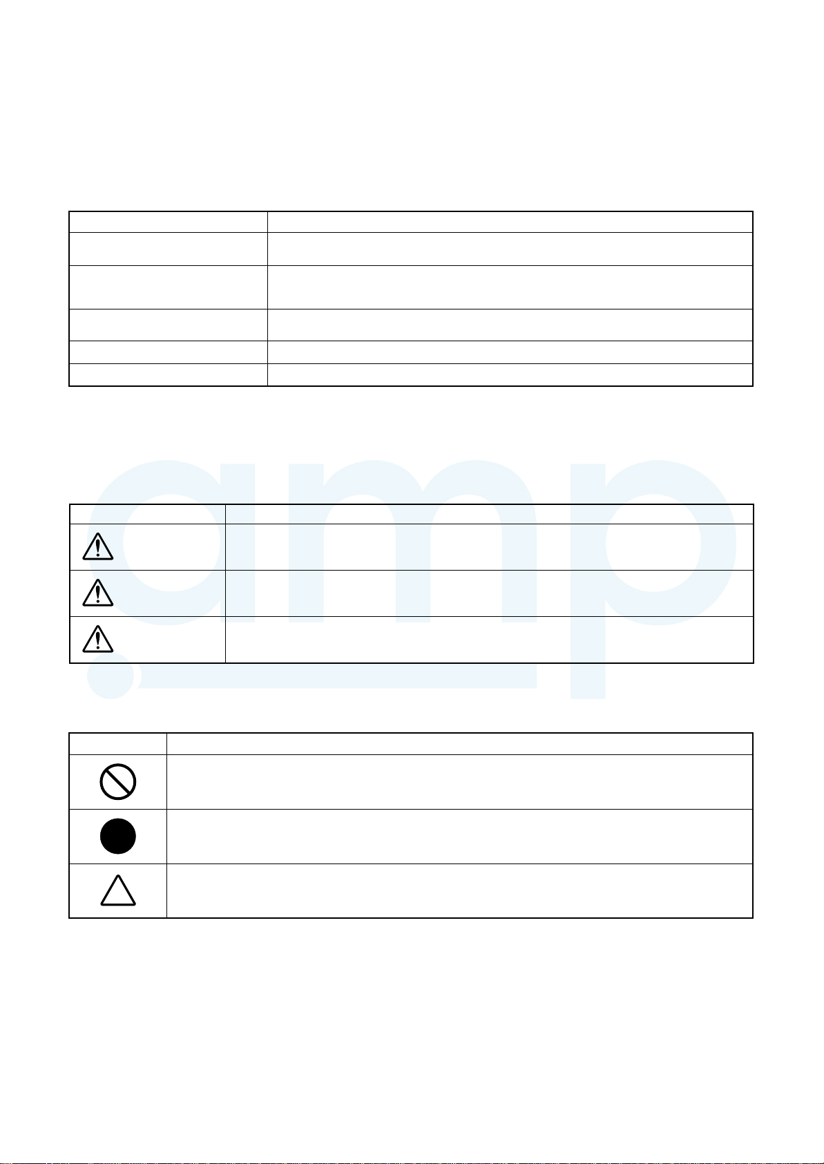
[Explanation of indications]
Indication Explanation
DANGER
WARNING
CAUTION
Indicates contents assumed that an imminent danger causing a death or serious injury of
the repair engineers and the third parties when an incorrect work has been executed.
Indicates possibilities assumed that a danger causing a death or serious injury of the
repair engineers, the third parties, and the users due to troubles of the product after work
when an incorrect work has been executed.
Indicates contents assumed that an injury or property damage (*) may be caused on the
repair engineers, the third parties, and the users due to troubles of the product after work
when an incorrect work has been executed.
* Property damage: Enlarged damage concerned to property, furniture, and domestic animal / pet
[Explanation of illustrated marks]
Indication Explanation
Indicates prohibited items (Forbidden items to do)
The sentences near an illustrated mark describe the concrete prohibited contents.
Indicates mandatory items (Compulsory items to do)
The sentences near an illustrated mark describe the concrete mandatory contents.
Indicates cautions (Including danger / warning)
The sentences or illustration near or in an illustrated mark describe the concrete cautious contents.
– 4 –
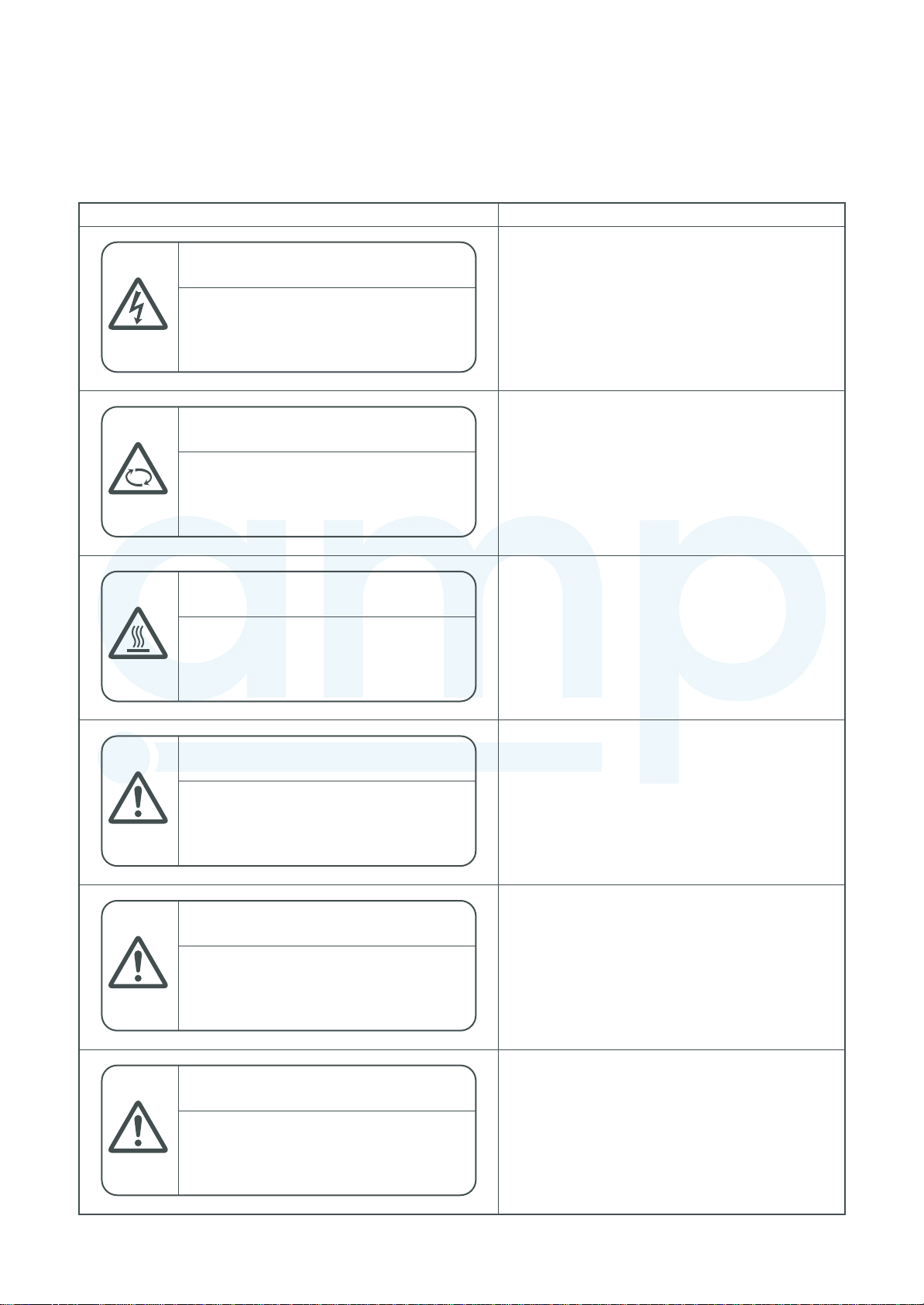
Warning Indications on the Air Conditioner Unit
AMP Air Conditioning
www.ampair.co.uk | sales@ampair.co.uk
[Confirmation of warning label on the main unit]
Confirm that labels are indicated on the specified positions
If removing the label during parts replace, stick it as the original.
Warning indication Description
WARNING
ELECTRICAL SHOCK HAZARD
Disconnect all remote electric
power supplies before servicing.
WARNING
Moving parts.
Do not operate unit with grille removed.
Stop the unit before the servicing.
CAUTION
High temperature parts.
You might get burned when removing
this panel.
WARNING
ELECTRICAL SHOCK HAZARD
Disconnect all remote electric power supplies
before servicing.
WARNING
Moving parts.
Do not operate unit with grille removed.
Stop the unit before the servicing.
CAUTION
High temperature parts.
You might get burned when removing this panel.
CAUTION
Do not touch the aluminium fins of the unit.
Doing so may result in injury.
CAUTION
BURST HAZARD
Open the service valves before the
operation, otherwise there might be the
burst.
CAUTION
Do not climb onto the fan guard.
Doing so may result in injury.
CAUTION
Do not touch the aluminium fins of the unit.
Doing so may result in injury.
CAUTION
BURST HAZARD
Open the service valves before the operation,
otherwise there might be the burst.
CAUTION
Do not climb onto the fan guard.
Doing so may result in injury.
– 5 –
PRECAUTIONS FOR SAFETY
AMP Air Conditioning
www.ampair.co.uk | sales@ampair.co.uk
The manufacturer shall not assume any liability for the damage caused by not observing the description of this
manual.
DANGER
Before carrying out the installation, maintenance, repair or removal work, be sure to set the circuit
breaker for both the indoor and outdoor units to the OFF position. Otherwise, electric shocks may
result.
Before opening the electrical box cover of the indoor unit or service panel of the outdoor unit, set the
circuit breaker to the OFF position. Failure to set the circuit breaker to the OFF position may result in
electric shocks through contact with the interior parts. Only a qualified installer (*1) or qualified service
person (*1) is allowed to remove the intake grille of the indoor unit or service panel of the outdoor unit
and do the work required.
Before opening the suction board cover, set the circuit breaker to the OFF position.
Failure to set the circuit breaker to the OFF position ma y result in injury through contact with the rotation parts.
Only a qualified installer (*1) or qualified service person (*1) is allowed to remove the suction board
Turn off
braeaker
Electric
shock hazard
Prohibition
Stay on
protection
cover and do the work required.
Before starting to repair the outdoor unit fan or fan guard, be absolutely sure to set the circuit breaker
to the OFF position, and place a “Work in progress” sign on the circuit breaker.
When cleaning the filter (sold separately) or other parts of the indoor unit, set the circuit breaker to OFF
without fail, and place a
When you have noticed that some kind of trouble (such as when an error display has appeared, there
is a smell of burning, abnormal sounds are heard, the air conditioner fails to cool or heat or water is
leaking) has occurred in the air conditioner, do not touch the air conditioner yourself but set the circuit
breaker to the OFF position, and contact a qualified service person. Take steps to ensure that the
power will not be turned on (by marking “out of service” near the circuit breaker, for instance) until
qualified service person arrives. Continuing to use the air conditioner in the trouble status may cause
mechanical problems to escalate or result in electric shocks or other failure.
When you access inside of the service panel to repair electric parts, wait for about five minutes after turning
off the breaker. Do not start repairing immediately.Otherwise you may get electric shock by touching
terminals of high-voltage capacitors. Natur al discharge of the capacitor tak es about five minutes.
When checking the electric parts, removing the cover of the electric parts box of Indoor Unit and/or
service panel of Outdoor Unit inevitably to determine the failure, use gloves to provide protection for
electricians, insulating shoes, clothing to provide protection from electric shock and insulating tools. Be
careful not to touch the live part. Electric shock may result. Only “Qualified service person” is allowed to
do this work.
Place a “Work in progress” sign near the circuit breaker while the installation, maintenance, repair or
removal work is being carried out.
There is a danger of electric shocks if the circuit breaker is set to ON by mistake.
When checking the electric parts, removing the cover of the electric parts box of Indoor Unit and/or
front panel of Outdoor Unit inevitably to determine the failure, put a sign “Do not enter” around the site
before the work. Failure to do this may result in third person getting electric shock.
Before operating the air conditioner after having completed the work, check that the electrical parts box
cover of the indoor unit and service panel of the outdoor unit are closed, and set the circuit breaker to
the ON position.
You may receive an electric shock if the power is turned on without first conducting these checks.
If, in the course of carrying out repairs, it becomes absolutely necessary to check out the electrical
parts with the electrical parts box cover of one or more of the indoor units and the service panel of the
outdoor unit removed in order to find out exactly where the trouble lies, wear insulated heat-resistant
gloves, insulated boots and insulated work overalls, and take care to avoid touching any live parts.
You may receive an electric shock if you fail to heed this warning. Only qualified service person (*1) is
allowed to do this kind of work.
“Work in progress” sign near the circuit breaker before proceeding with the work.
– 6 –
W ARNIG
AMP Air Conditioning
www.ampair.co.uk | sales@ampair.co.uk
General
Before starting to repair the air conditioner, read carefully through the Service Manual, and repair the
air conditioner by following its instructions.
Only qualified service person (*1) is allowed to repair the air conditioner.
Repair of the air conditioner by unqualified person may give rise to a fire, electric shocks, injury, water
leaks and / or other problems.
Do not use any refrigerant different from the one specified for complement or replacement.
Otherwise, abnormally high pressure may be generated in the refrigeration cycle, which may result in a
failure or explosion of the product or an injury to your body.
Only a qualified installer (*1) or qualified service person (*1) is allowed to carry out the electrical work
of the air conditioner.
Under no circumstances must this work be done by an unqualified individual since failure to carry out
the work properly may result in electric shocks and / or electrical leaks.
When the air conditioner is to be transported, installed, maintained, repaired or removed, wear
protective gloves and ‘safety’ work clothing.
To connect the electrical wires, repair the electrical parts or undertake other electrical jobs, wear gloves
to provide protection for electricians, insulating shoes and clothing to provide protection from electric
shocks. Failure to wear this protective gear may result in electric shocks.
Electrical wiring work shall be conducted according to law and regulation in the community and
installation manual. Failure to do so may result in electrocution or short circuit.
Use wiring that meets the specifications in the Installation Manual and the stipulations in the local
regulations and laws. Use of wiring which does not meet the specifications may give rise to electric
shocks, electrical leakage, smoking and/or a fire.
Only a qualified installer (*1) or qualified service person (*1) is allowed to undertake work at heights
using a stand of 50 cm or more or to remove the intake gr ille of the indoor unit to undertake work.
When working at heights, use a ladder which complies with the ISO 14122 standard, and follow the
procedure in the ladder’s instructions.
Also wear a helmet for use in industry as protective gear to undertake the work.
Before working at heights, put a sign in place so that no-one will approach the work location,
before proceeding with the work. Parts and other objects may fall from above, possibly injur ing a
person below. While carrying out the work, wear a helmet for protection from falling objects.
When executing address setting, test run, or troubleshooting through the checking window on the
electric parts box, put on insulated gloves to provide protection from electric shock. Otherwise you may
receive an electric shock.
Do not touch the aluminum fin of the outdoor unit.
You may injure yourself if you do so. If the fin must be touched for some reason, first put on protective
gloves and safety work clothing, and then proceed.
Do not climb onto or place objects on top of the outdoor unit.
You may fall or the objects may fall off of the outdoor unit and result in injury.
Use forklift to carry in the air conditioner units and use winch or hoist at installation of them.
When transporting the air conditioner, wear shoes with protective toe caps, protective gloves and other
protective clothing.
When transporting the air conditioner, do not take hold of the bands around the packing carton.
You may injure yourself if the bands should break.
Be sure that a heavy unit (10 kg or heavier) such as a compressor is carried by four persons.
This air conditioner has passed the pressure test as specified in IEC 60335-2-40 Annex EE.
Before troubleshooting or repair work, check the earth wire is connected to the earth terminals of the main unit,
otherwise an electric shock is caused when a leak occurs.If the earth wire is not correctly connected,
contact an electric engineer for rework.
Check earth
wires.
After completing the repair or relocation work, check that the ground wires are connected properly.
Be sure to connect earth wire. (Grounding work) Incomplete grounding causes an electric shock.
Do not connect ground wires to gas pipes, water pipes, and lightning rods or ground wires for
telephone wires.
– 7 –
Prohibition of
AMP Air Conditioning
www.ampair.co.uk | sales@ampair.co.uk
modification.
Use specified
parts.
Do not bring
a child close
to the
equipment.
Insulating
measures
No fire
Refrigerant
Do not modify the products.Do not also disassemble or modify the parts.
It may cause a fire, electric shock or injury.
When any of the electrical parts are to be replaced, ensure that the replacement par ts satisfy the
specifications given in the Service Manual (or use the parts contained on the parts list in the
Service Manual).
Use of any parts which do not satisfy the required specifications may give rise to electric shocks,
smoking and / or a fire.
If, in the course of carrying out repairs, it becomes absolutely necessary to check out the electrical
parts with the electrical parts box cover of one or more of the indoor units and the service panel of the
outdoor unit removed in order to find out exactly where the trouble lies, put a sign in place so that noone will approach the work location before proceeding with the work. Third-par ty individuals may enter
the work site and receive electric shocks if this warning is not heeded.
Connect the cut-off lead wires with crimp contact, etc., put the closed end side upward and then apply
a watercut method, otherwise a leak or production of fire is caused at the users’ side.
When performing repairs using a gas burner, replace the refrigerant with nitrogen gas because the oil
that coats the pipes may otherwise burn.
When repairing the refrigerating cycle, take the following measures.
1) Be attentive to fire around the cycle. When using a gas stove, etc., be sure to put out fire bef ore w ork;
otherwise the oil mixed with refrigerant gas may catch fire.
2) Do not use a welder in the closed room. When using it without ventilation, carbon monoxide
poisoning may be caused.
3) Do not bring inflammables close to the refrigerant cycle, otherwise fire of the welder may catch the
inflammables.
The refrigerant used by this air conditioner is the R410A.
Check the used refrigerant name and use tools and materials of the parts which match with it.
For the products which use R410A refrigerant, the refrigerant name is indicated at a position on the
outdoor unit where is easy to see. To prevent miss-charging, the route of the service port is changed
from one of the former R22.
Do not use any refrigerant different from the one specified for complement or replacement.
Otherwise, abnormally high pressure may be generated in the refrigeration cycle, which may result in a
failure or explosion of the product or an injury to your body.
For an air conditioner which uses R410A, never use other refr igerant than R410A. For an air
conditioner which uses other refrigerant (R22, etc.), never use R410A.
If different types of refrigerant are mixed, abnormal high pressure generates in the refrigerating cycle
and an injury due to breakage may be caused.
When the air conditioner has been installed or relocated, follow the instructions in the Installation
Manual and purge the air completely so that no gases other than the refrigerant will be mixed in the
refrigerating cycle.
Failure to purge the air completely may cause the air conditioner to malfunction.
Do not charge refrigerant additionally. If charging refrigerant additionally when refrigerant gas leaks, the
refrigerant composition in the refrigerating cycle changes resulted in change of air conditioner
characteristics or refrigerant over the specified standard amount is charged and an abnormal high
pressure is applied to the inside of the refrigerating cycle resulted in cause of breakage or injury.
Therefore if the refrigerant gas leaks, recover the refrigerant in the air conditioner, execute vacuuming,
and then newly recharge the specified amount of liquid refrigerant.
In this time, never charge the refrigerant over the specified amount.
When recharging the refrigerant in the refrigerating cycle, do not mix the refrigerant or air other than
R410A into the specified refrigerant. If air or others is mixed with the refrigerant, abnormal high
pressure generates in the refrigerating cycle resulted in cause of injury due to breakage.
After installation work, check the refrigerant gas does not leak. If the refrigerant gas leaks in the room,
poisonous gas generates when gas touches to fire such as fan heater, stove or cocking stove though
the refrigerant gas itself is innocuous.
Never recover the refrigerant into the outdoor unit. When the equipment is moved or repaired, be sure
to recover the refrigerant with recover ing device.
The refrigerant cannot be recovered in the outdoor unit; otherwise a serious accident such as breakage
or injury is caused.
– 8 –
Assembly /
AMP Air Conditioning
www.ampair.co.uk | sales@ampair.co.uk
Wiring
Insulator
check
Ventilation
Compulsion
Check after
repair
After repair work, surely assemble the disassembled parts, and connect and lead the removed wires as before .
Perform the work so that the cabinet or panel does not catch the inner wires.
If incorrect assembly or incorrect wire connection was done, a disaster such as a leak or fire is caused
at user’s side.
After the work has finished, be sure to use an insulation tester set (500 V Megger) to check the resistance is
1 MΩ or more between the charge section and the non-charge metal section (Earth position).
If the resistance value is low, a disaster such as a leak or electric shock is caused at user’s side.
When the refrigerant gas leaks during work, execute ventilation.
If the refrigerant gas touches to a fire, poisonous gas generates. A case of leakage of the refrigerant
and the closed room full with gas is dangerous because a shortage of oxygen occurs. Be sure to
execute ventilation.
If refrigerant gas has leaked during the installation work, ventilate the room immediately.
If the leaked refrigerant gas comes in contact with fire, noxious gas may generate.
After installation work, check the refrigerant gas does not leak. If the refrigerant gas leaks in the room,
poisonous gas generates when gas touches to fire such as fan heater, stove or cocking stove though
the refrigerant gas itself is innocuous.
When the refrigerant gas leaks, find up the leaked position and repair it surely.
If the leaked position cannot be found up and the repair work is interrupted, pump-down and tighten the
service valve, otherwise the refrigerant gas may leak into the room.
The poisonous gas generates when gas touches to fire such as fan heater , stove or cocking stove though
the refrigerant gas itself is innocuous.
When installing equipment which includes a large amount of charged refrigerant such as a multi air
conditioner in a sub-room, it is necessary that the density does not the limit even if the refrigerant leaks.
If the refrigerant leaks and exceeds the limit density, an accident of shortage of oxygen is caused.
Tighten the flare nut with a torque wrench in the specified manner.
Excessive tighten of the flare nut may cause a crack in the flare nut after a long period, which may
result in refrigerant leakage.
Nitrogen gas must be used for the airtight test.
The charge hose must be connected in such a way that it is not slack.
For the installation / moving / reinstallation work, follow to the Installation Manual.
If an incorrect installation is done, a trouble of the refrigerating cycle, water leak, electric shoc k or fire is caused.
Once the repair work has been completed, check for refrigerant leaks, and check the insulation
resistance and water drainage.
Then perform a trial run to check that the air conditioner is running properly.
After repair work has finished, check there is no trouble. If check is not executed, a fire, electric shock
or injury may be caused. For a check, turn off the power breaker.
After repair work (installation of front panel and cabinet) has finished, execute a test run to check there
is no generation of smoke or abnormal sound.
If check is not ex ecuted, a fire or an electric shock is caused. Bef ore test run, install the front panel and cabinet.
Be sure to fix the screws back which have been removed for installation or other purposes.
Check the following matters before a test r un after repairing piping.
• Connect the pipes surely and there is no leak of refrigerant.
• The valve is opened.
Do not
operate the
unit with the
valve closed.
Check after
reinstallation
Running the compressor under condition that the valve closes causes an abnormal high pressure
resulted in damage of the parts of the compressor and etc. and moreover if there is leak of refrigerant
at connecting section of pipes, the air is sucked and causes further abnormal high pressure resulted in
burst or injury.
Only a qualified installer (*1) or qualified service person (*1) is allowed to relocate the air conditioner. It
is dangerous for the air conditioner to be relocated by an unqualified individual since a fire, electric
shocks, injury, water leakage, noise and / or vibration may result.
Check the following items after reinstallation.
1) The earth wire is correctly connected.
2) The power cord is not caught in the product.
3) There is no inclination or unsteadiness and the installation is stable.
If check is not executed, a fire, an electric shock or an injury is caused.
When carrying out the pump-down work shut down the compressor before disconnecting the refrigerant pipe.
Disconnecting the refrigerant pipe with the service valve left open and the compressor still operating
will cause air, etc. to be sucked in, raising the pressure inside the refrigeration cycle to an abnormally
high level, and possibly resulting in reputing, injury, etc.
– 9 –
Cooling check
AMP Air Conditioning
www.ampair.co.uk | sales@ampair.co.uk
Installation
When the service panel of the outdoor unit is to be opened in order for the compressor or the area
around this part to be repaired immediately after the air conditioner has been shut down, set the circuit
breaker to the OFF position, and then wait at least 10 minutes before opening the service panel.
If you fail to heed this warning, you will run the risk of burning yourself because the compressor pipes
and other parts will be very hot to the touch. In addition, before proceeding with the repair work, wear
the kind of insulated heat-resistant gloves designed to protect electricians.
Take care not to get burned by compressor pipes or other parts when checking the cooling cycle while
running the unit as they get heated while running. Be sure to put on gloves providing protection for heat.
When the service panel of the outdoor unit is to be opened in order for the fan motor, reactor, inverter
or the areas around these parts to be repaired immediately after the air conditioner has been shut
down, set the circuit breaker to the OFF position, and then wait at least 10 minutes before opening the
service panel.
If you fail to heed this warning, you will run the risk of burning yourself because the fan motor, reactor,
inverter heat sink and other parts will be very hot to the touch.
In addition, before proceeding with the repair work, wear the kind of insulated heat-resistant gloves
designed to protect electricians.
Only a qualified installer or service person is allowed to do installation work. Inappropriate installation
may result in water leakage, electric shock or fire.
Before starting to install the air conditioner, read carefully through the Installation Manual, and follow its
instructions to install the air conditioner.
Be sure to use the company-specified products for the separately purchased parts. Use of nonspecified products may result in fire, electric shock, water leakage or other failure. Have the installation
performed by a qualified installer.
Do not supply power from the power terminal block equipped on the outdoor unit to another outdoor unit.
Capacity overflow may occur on the terminal block and may result in fire.
Do not install the air conditioner in a location that may be subject to a risk of expire to a combustible gas .
If a combustible gas leaks and becomes concentrated around the unit, a fire may occur.
Install the indoor unit at least 2.5 m above the floor level since otherwise the users may injure
themselves or receive electric shocks if they poke their fingers or other objects into the indoor unit
while the air conditioner is running.
Install a circuit breaker that meets the specifications in the installation manual and the stipulations in
the local regulations and laws.
Install the circuit breaker where it can be easily accessed by the qualified service person (*1).
If you install the unit in a small room, take appropriate measures to prevent the refrigerant from
exceeding the limit concentration even if it leaks. Consult the dealer from whom you purchased the air
conditioner when you implement the measures. Accumulation of highly concentrated refrigerant may
cause an oxygen deficiency accident.
Do not place any combustion appliance in a place where it is directly exposed to the wind of air
conditioner, otherwise it may cause imperfect combustion.
Explanations given to user
If you have discovered that the fan grille is damaged, do not approach the outdoor unit but set the circuit
breaker to the OFF position, and contact a qualified service person to have the repairs done.
Do not set the circuit breaker to the ON position until the repairs are completed.
Relocation
• Only a qualified installer (*1) or qualified ser vice person (*1) is allowed to relocate the air conditioner.
It is dangerous for the air conditioner to be relocated by an unqualified individual since a fire, electric shocks,
injury, water leakage, noise and / or vibration may result.
• When carrying out the pump-down work shut down the compressor before disconnecting the refrigerant pipe.
Disconnecting the refrigerant pipe with the service valve left open and the compressor still operating will
cause air, etc. to be sucked in, raising the pressure inside the refrigeration cycle to an abnormally high level,
and possibly resulting in reputing, injury, etc.
(*1) Refer to the “Definition of Qualified Installer or Qualified Service Person”
– 10 –

Declaration of Conformity
AMP Air Conditioning
www.ampair.co.uk | sales@ampair.co.uk
Manufacturer:
Authorized Representative / Nick Ball
TCF holder: Toshiba EMEA Engineering Director
Hereby declares that the machinery described below:
Generic Denomination: Air Conditioner
Model / type: Indoor unit
TOSHIBA CARRIER (THAILAND) CO., LTD.
144 / 9 Moo 5, Bangkadi Industrial Park, Tivanon Road, Tambol Bangkadi,
Amphur Muang, Pathumthani 12000, Thailand
Toshiba Carrier UK Ltd.
Porsham Close, Belliver Industrial Estate,
PLYMOUTH, Devon, PL6 7DB.
United Kingdom
<Concealed Duct High Static Pressure Type>
MMD-AP0186HP-E,
MMD-AP0246HP-E,
MMD-AP0276HP-E,
MMD-AP0366HP-E,
MMD-AP0486HP-E,
MMD-AP0566HP-E
MMD-AP0186HP-TR,
MMD-AP0246HP-TR,
MMD-AP0276HP-TR,
M
MD-AP0366HP-TR,
MMD-AP0486HP-TR,
MMD-AP0566HP-TR
Commercial name: Super Modular Multi System Air Conditioner
Super Heat Recovery Multi System Air Conditioner
MiNi-Super Modular Multi System Air Conditioner (MiNi-SMMS series)
Complies with the provisions of the “Machinery” Directive (Directive 2006/42/EC) and the regulations
transposing into national law
“Declaration of incorporation of partly completed machinery”
Must not be put into service until the final machinery into which it is to be incorporated has been declared in
conformity with the provisions of this Directive, where appropriate.
NOTE
This declaration becomes invalid if technical or operational modifications are introduced without the
manufacturer’s consent.
– 11 –
Specifications
AMP Air Conditioning
www.ampair.co.uk | sales@ampair.co.uk
Model
MMD-AP0186HP-E
MMD-AP0246HP-E
MMD-AP0276HP-E
MMD-AP0366HP-E
MMD-AP0486HP-E
MMD-AP0566HP-E
MMD-AP0186HP-TR
MMD-AP0246HP-TR
MMD-AP0276HP-TR
MMD-AP0366HP-TR
MMD-AP0486HP-TR
MMD-AP0566HP-TR
: Under 70 dBA
∗
Sound pressure level (dBA)
Cooling Heating
∗
∗
∗
∗
∗
∗
∗
∗
∗
∗
∗
∗
∗
∗
∗
∗
∗
∗
∗
∗
∗
∗
∗
∗
Weight (kg)
Main unit
34
34
34
43
43
43
34
34
34
43
43
43
– 12 –
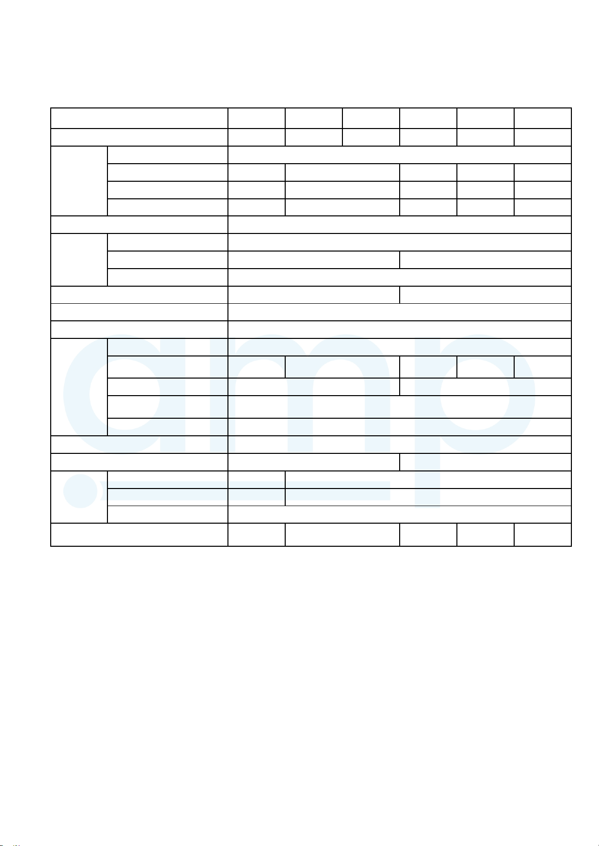
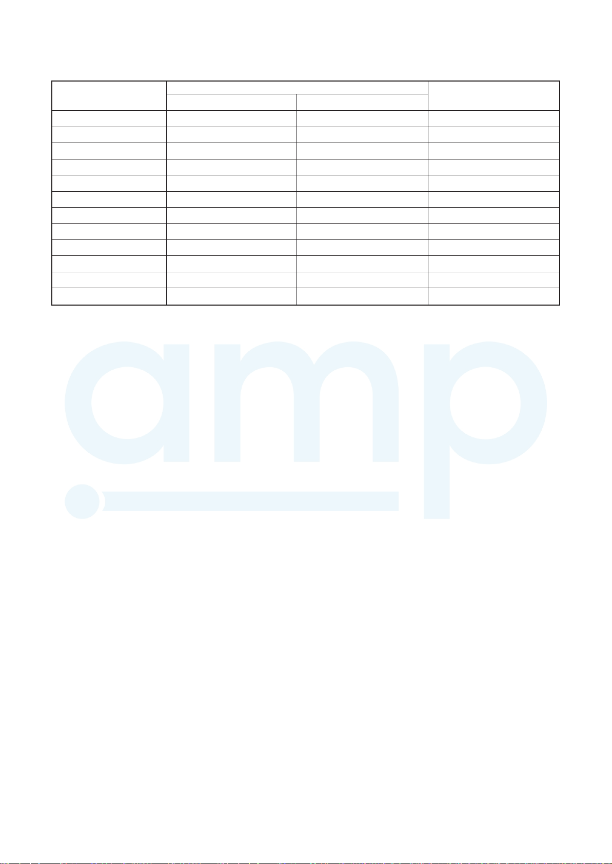
1. SPECIFICATIONS
AMP Air Conditioning
www.ampair.co.uk | sales@ampair.co.uk
Concealed Duct High Static Pressure Type
Model name MMD-
Cooling/Heating capacity (Note 1) (kW)
Electrical Power supply
characteristics Running current (A) 0.52 0.70 1.17 1.34 1.68
Power consumption (kW) 0.085 0.115 0.198 0.230 0.290
Starting current (A) 0.78 1.05 1.75 2.01 2.51
Appearance
Dimension Height (mm)
Width (mm)
Depth (mm)
Total weight (kg)
Heat exchanger
Soundproof / Heat-insulating meterial
Fan unit Fan
(m3/h) 800 1,200 1,920 2,100 2,400Standard air flow
(Med./Low) (660/550) (970/800) (1560/1340) (1740/1420) (2040/1660)
Motor output (W)
External static pressure
(factory setting)
External static pressure (Pa)
Controller
Air filter
(Pa)
AP0186
HP-E(TR)
5.6/6.3 7.1/8.0 8.0/9.0 11.2/12.5 14.0/16.0 16.0/18.0
Sold separately (TCB-LK801D-E) Sold separately (TCB-LK1401D-E)
AP0246
HP-E(TR)
1000
34
250 350
AP0276
HP-E(TR)
1phase 50Hz 230V(220V-240V)
Zinc hot dipping steel plate
Finned tube
Polyethlene foam
Centrifugal fan
50-75-100-125-150-175-200 (7steps)
Remote controller
AP0366
HP-E(TR)
298
750
100
AP0486
HP-E(TR)
1400
43
AP0566
HP-E(TR)
(50Hz)
Connecting Gas side (mm) 12.7
pipe Liquid side (mm) 6.4
Drain port (mm)
Sound pressure level (Note 2)
(High/Med./Low) (32/30) (34/31) (37/34) (40/35) (42/37)
Note 1 : The cooling capacities and electrical characteristics are measured under the conditions specified by JIS B 8615 based
on the reference piping.
The reference piping consists of 5m of main piping and 2.5m of branch piping connected with 0 meter height.
Note 2 : The sound level are measured in an anechoic chamber in accordance with JIS B 8616.
Normally, the values measured in the actual operating environment become larger than the indicated valves due to the
effects of external sound.
Note: Rated conditions Cooling: Indoor air temperature 27℃ DB/19℃ WB, Outdoor air temperature 35℃ DB
Heating: Indoor air temperature 20℃ DB, Outdoor air temperature 7℃ DB/6℃ W B
(dB(A)) 37 38 41 42 45
25(Polyvinyl chloride tube)
15.9
9.5
– 13 –
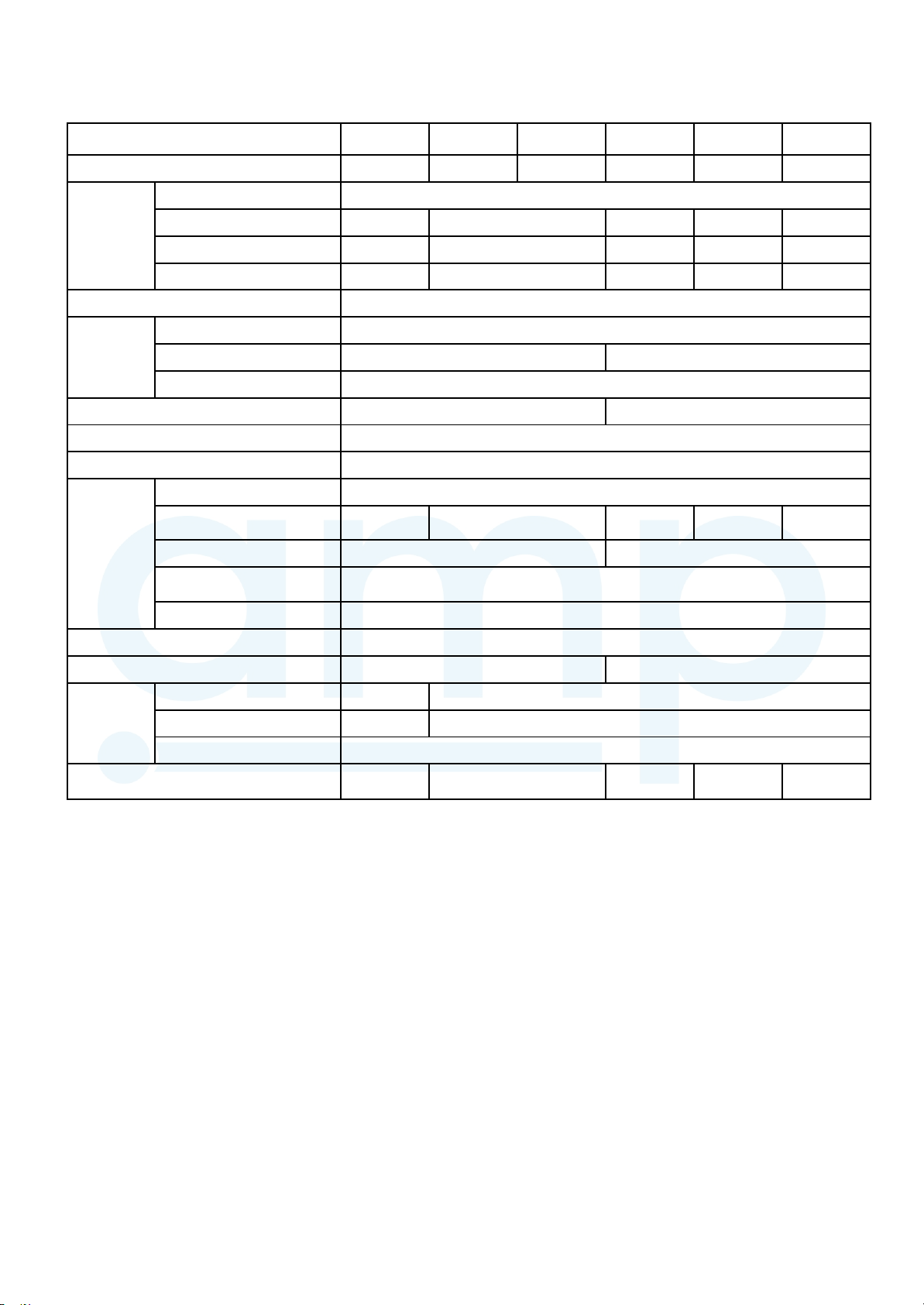
(60Hz)
AMP Air Conditioning
www.ampair.co.uk | sales@ampair.co.uk
Model name MMD-
Cooling/Heating capacity (Note 1) (kW)
AP0186
HP-E
5.6/6.3 7.1/8.0 8.0/9.0 11.2/12.5 14.0/16.0 16.0/18.0
Electrical Power supply
characteristics Running current (A) 0.54 0.73 1.22 1.40 1.75
Power consumption (kW) 0.085 0.115 0.198 0.230 0.290
Starting current (A) 0.81 1.10 1.83 2.10 2.63
Appearance
Dimension Height (mm)
Width (mm)
Depth (mm)
Total weight (kg)
Heat exchanger
Soundproof / Heat-insulating meterial
Fan unit Fan
(m3/h) 800 1,200 1,920 2,100 2,400Standard air flow
(Med./Low) (660/550) (970/800) (1560/1340) (1740/1420) (2040/1660)
Motor output (W)
External static pressure
(Pa)
(factory setting)
External static pressure (Pa)
Controller
Air filter Sold separately (TCB-LK801D-E) Sold separately (TCB-LK1401D-E)
AP0246
HP-E
AP0276
HP-E
AP0366
HP-E
AP0486
1phase 60Hz 220V
Zinc hot dipping steel plate
298
1000 1400
750
34 43
Finned tube
Polyethlene foam
Centrifugal fan
250 350
100
50-75-100-125-150-175-200 (7steps)
Remote controller
HP-E
AP0566
HP-E
Connecting Gas side (mm) 12.7
pipe Liquid side (mm) 6.4
Drain port (mm)
Sound pressure level (Note 2)
(dB(A)) 37 38 41 42 45
25(Polyvinyl chloride tube)
15.9
9.5
(High/Med./Low) (32/30) (34/31) (37/34) (40/35) (42/37)
Note 1 : The cooling capacities and electrical characteristics are measured under the conditions specified by JIS B 8615 based
on the reference piping.
The reference piping consists of 5m of main piping and 2.5m of branch piping connected with 0 meter height.
Note 2 : The sound level are measured in an anechoic chamber in accordance with JIS B 8616.
Normally, the values measured in the actual operating environment become larger than the indicated valves due to the
effects of external sound.
Note: Rated conditions Cooling: Indoor air temperature 27℃ DB/19℃ WB, Outdoor air temperature 35℃ DB
Heating: Indoor air temperature 20℃ DB, Outdoor air temperature 7℃ DB/6℃ W B
– 14 –
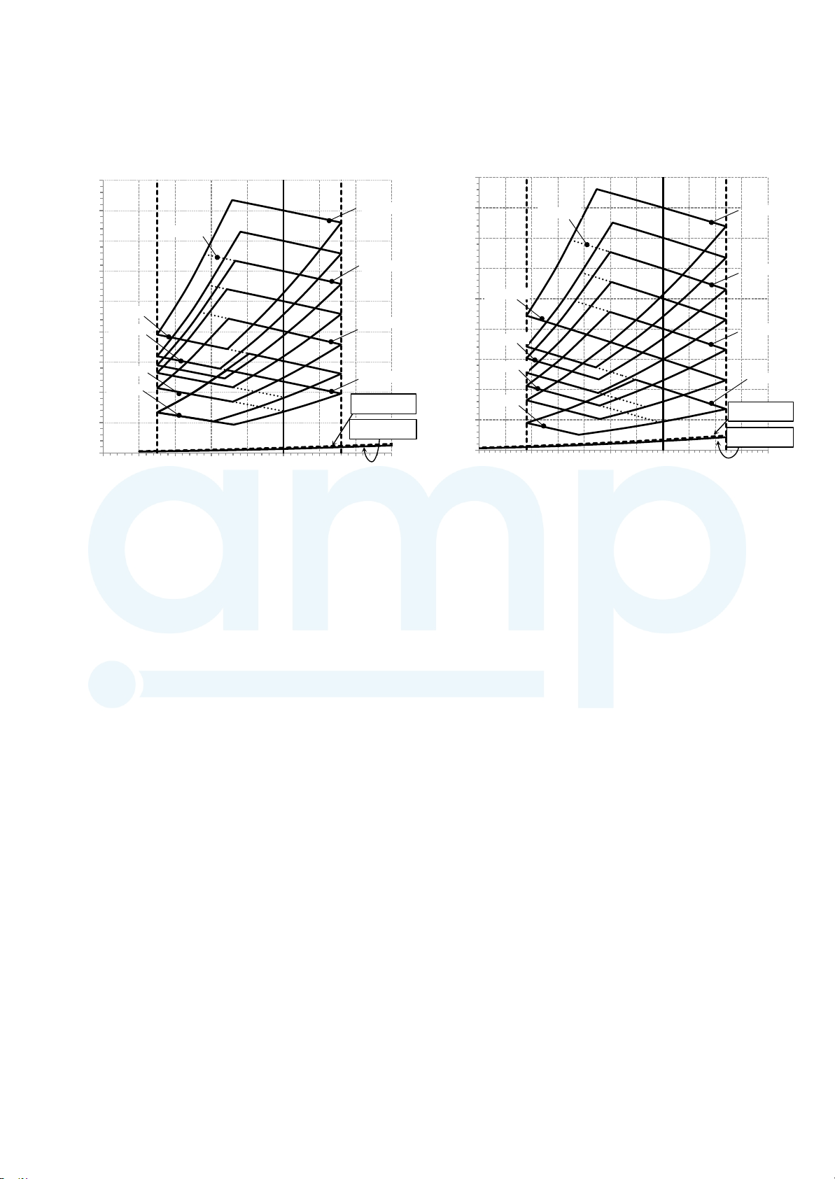
2. AIR DUCTING WORK
AMP Air Conditioning
www.ampair.co.uk | sales@ampair.co.uk
AP0186 type
225
200
175
150
125
200Pa-Low
150Pa-Low
100
Static Pressure (Pa)
75
100Pa-Low
50Pa-Low
50
25
0
300
400
200Pa-Mid
500
Air Flow (m3/h)
Standard Air Flow 800m3/h
600
700
AP0246, 0276 type
225
200Pa-High
200
200Pa-Mid
175
150Pa-High
100Pa-High
50Pa-High
Spigod Flange
pressure loss (option)
Filter set.
pressure loss (option)
150
200Pa-Low
125
100
75
50
150Pa-Low
100Pa-Low
50Pa-Low
Static Pressure (Pa)
25
0
500
600
800
900
1000
1100
700
Standard Air Flow 1,200m3/h
800
900
Air Flow (m3/h)
1000
200Pa-High
150Pa-High
100Pa-High
50Pa-High
Spigod Flange
pressure loss (option)
Filter set.
pressure loss (option)
1100
1200
1300
1400
1500
1600
– 15 –

AP0366 type AP0486 type
AMP Air Conditioning
www.ampair.co.uk | sales@ampair.co.uk
250
Standard Air Flow 1,920m3/h
250
Standard Air Flow 2,100m3/h
225
200
175
150
200Pa-Low
125
150Pa-Low
100
Static Pressure (Pa)
75
100Pa-Low
50
25
50Pa-Low
0
600
AP0566 type
250
225
200
225
200Pa-Mid
200Pa-High
200
200Pa-Mid
200Pa-High
175
150Pa-High
150
200Pa-Low
150Pa-High
125
100Pa-High
150Pa-Low
100
Static Pressure (Pa)
100Pa-High
75
50Pa-High
Spigod Flange
pressure loss (option)
Filter set.
pressure loss (option)
800
1000
1200
1400
1600
1800
2000
2200
2400
Air Flow (m3/h)
Standard Air Flow 2,400m3/h
200Pa-Mid
2600
200Pa-High
50
25
0
100Pa-Low
50Pa-Low
800
1000
1200
1400
1600
Air Flow (m3/h)
1800
2000
2200
50Pa-High
Spigod Flange
pressure loss (option)
Filter set.
pressure loss (option)
2400
2600
2800
Static Pressure (Pa)
175
150
125
100
75
50
25
0
200Pa-Low
150Pa-Low
100Pa-Low
50Pa-Low
1000
150Pa-High
100Pa-High
50Pa-High
Spigod Flange
pressure loss (option)
Filter set.
pressure loss (option)
1200
1400
1600
1800
2000
2200
2400
2600
2800
Air Flow (m3/h)
3000
– 16 –
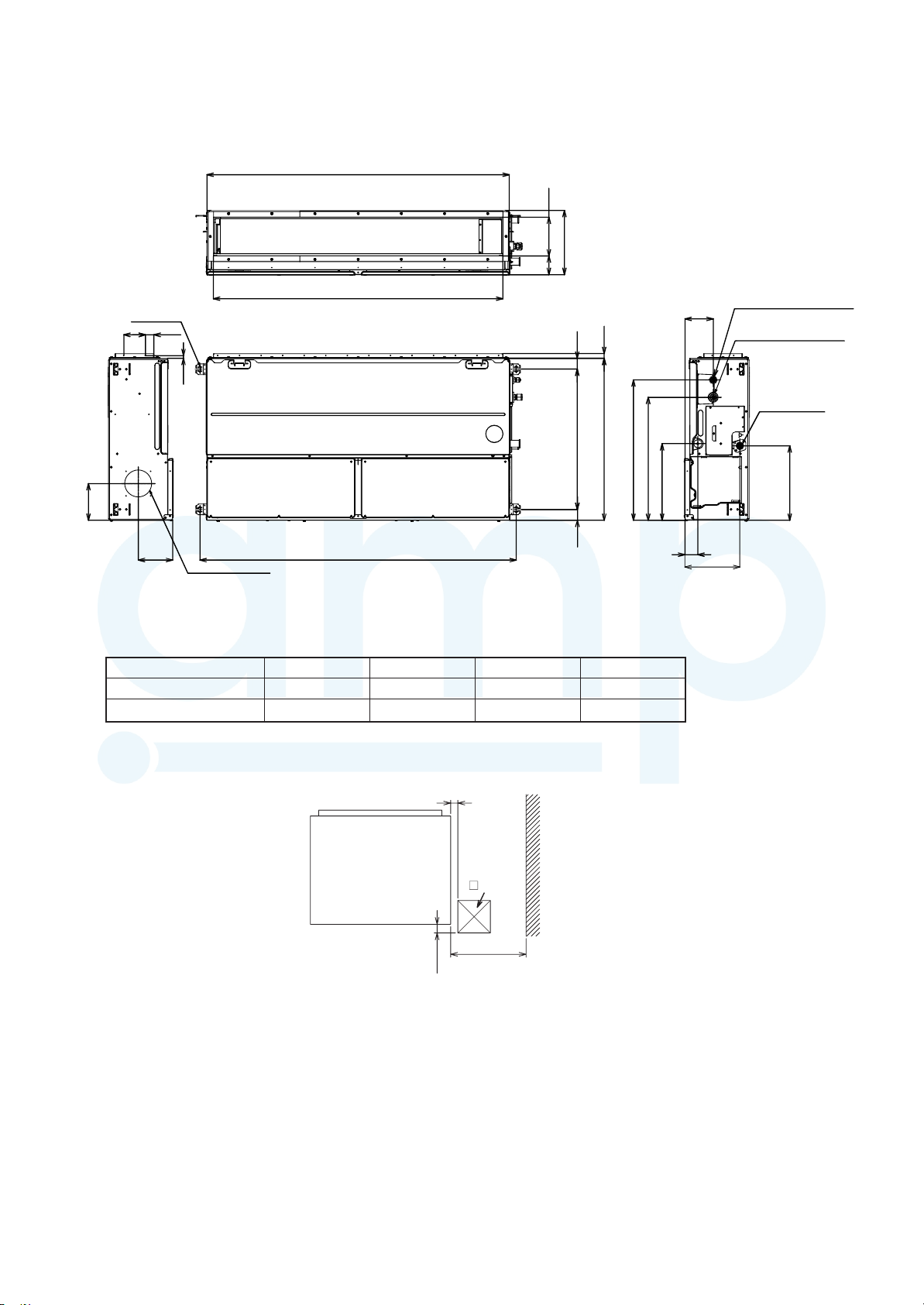
3. CONSTRUCTION VIEWS (EXTERNAL VIEWS)
AMP Air Conditioning
www.ampair.co.uk | sales@ampair.co.uk
Main unit dimension A
180
298
87
Hole for hanging bolt
(4-Φ12×30)
170
Dimension
AP018~027 type
AP036~056 type
40100
13
160
Φ125 K nockout hole
For Auxi liary fresh ai r flan ge
(Sold se parate ly)
External dimension C
22
750
650 5050
Hanging bolt mounting pitch
Hanging bolt mounting pitch B
650
570
355
ABCD
1000 1065 940
1400 1465 1340
500
700
Refrigerant pipe
131
60
connecting port (Liquid side)
Refrigerant pipe
connecting port (Gas side)
Drain pipe
connecting port
255
345
Air discharge
100 or more
Check port
450
120
D
Service space
(D for maintenance of air filter(Sold separately))
– 17 –
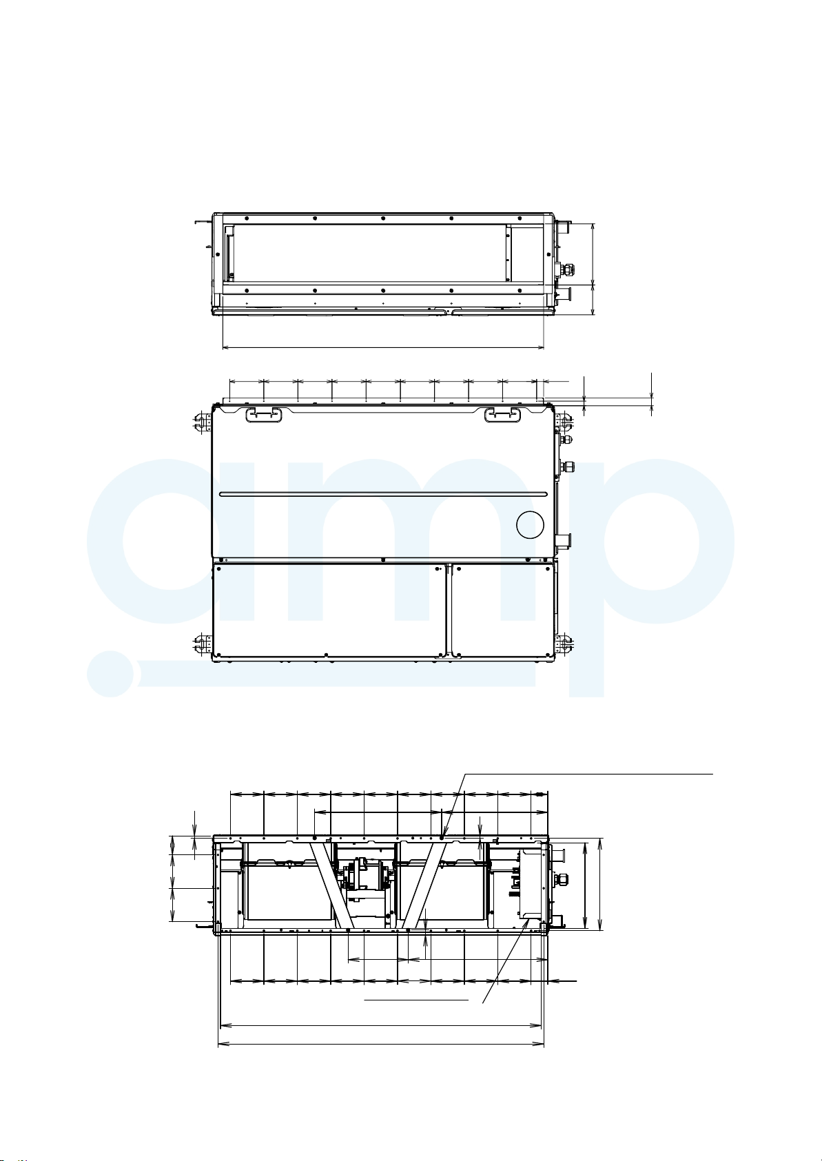
Duct arrangement
AMP Air Conditioning
www.ampair.co.uk | sales@ampair.co.uk
AP0186, AP0246, AP0276
<Air outlet>
940
(Outside)
87 180
(Outside)
<Air inlet>
100 100 100 100
8
There are the head of the screw(n=4).
Make a hole at the installation of inlet duct.
100 100 100 100 100 50
380 318
7
20100100100100100100100100100
13
22
100 57
100
15
100
100 100 100 100 100
Electrical control box
960
975
– 18 –
276
256
418 180
100 100 100
50
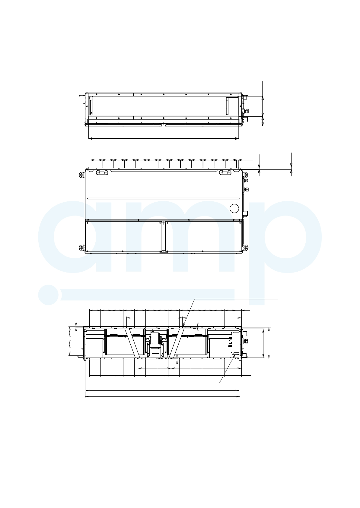
AP0366, AP0486, AP0566
AMP Air Conditioning
www.ampair.co.uk | sales@ampair.co.uk
<Air outlet>
1340
(Outside)
(Outside)
180
87
20100100100100100100100100100100100100100
13
(Unit : mm)
22
8
100 100 57
<Air inlet>
There are the head of the screw(n=4).
Make a hole at the installation of inlet duct.
100 100 100 100 100 100 100 100 100 100 100 100 100
496 524
7
15
100
Electrical control box
1360
1375
624 293
50
276
256
100 100 100 100 100 100 100 100 100 100 100 100
50
–
19 –
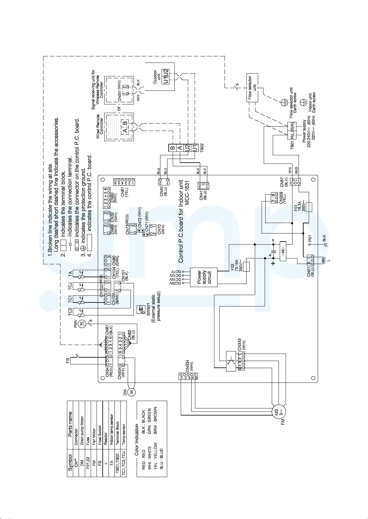
4.WIRING DIAGRAMS
AMP Air Conditioning
www.ampair.co.uk | sales@ampair.co.uk
–
20 –
5. PARTS RATING
AMP Air Conditioning
www.ampair.co.uk | sales@ampair.co.uk
Model MMD-AP 0186HP* 0246HP* 0276HP* 0366HP* 0486HP* 0566HP*
Fan motor
Drain pump motor
Float switch
Pulse motor
Pulse motor valve
TA sensor
TC1 sensor
TC2 sensor
TCJ sensor
ICF-340W250-2 MF-340W350-1
MDP-1401, PMD-08D12TF-1
FS-1A-31-3
EFM-MD12TF-1
EFM-60YGTCTH-1EFM-40YGTF-1
Lead wire length:230mm
∅4 size lead wire length:1000mm Vinyl tube (Blue)
∅6 size lead wire length:1000mm Vinyl tube (Black)
∅6 size lead wire length:1000mm Vinyl tube (Red)
–
21 –
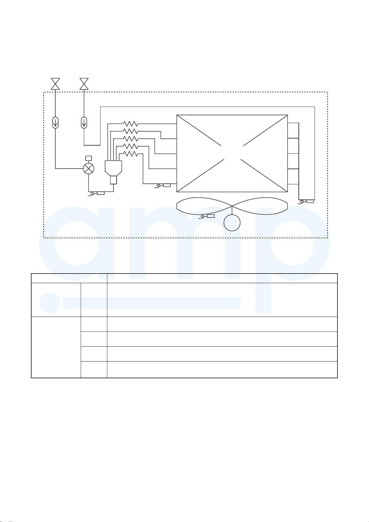
6. REFRIGERANT CYCLE DIAGRAM
AMP Air Conditioning
www.ampair.co.uk | sales@ampair.co.uk
Indoor unit
Gas sideLiquid side
Strainer
Pulse Motor
Valve (PMV)
Sensor
(TC2)
Capillary tube
Strainer
Sensor
(TCJ)
Explanation of functional parts in indoor unit
Functional part name
Pulse Motor Valve
PMV
Temp. Sensor (Connector CN104 (2P): Yellow)
1.TA
2.TC1
3.TC2
4.TCJ
(Connector CN082 (6P): Blue)
1) Controls super heat in cooling operation
2) Controls under cool in heating operation
3) Recovers refrigerant oil in cooling operation
4) Recovers refrigerant oil in heating operation
1) Detects indoor suction temperature
(Connector CN100 (3P): Brown)
1) Controls PMV super heat in cooling operation
(Connector CN101 (2P): Black)
1) Controls PMV under cool in heating operation
(Connector CN102 (2P): Red)
1) Controls PMV super heat in cooling operation
Heat exchanger
at indoor side
Fan
Sensor
(TA)
Functional outline
M
Sensor
(TC1)
Fan motor
–
22 –
7. CONTROL OUTLINE
AMP Air Conditioning
www.ampair.co.uk | sales@ampair.co.uk
Indoor unit
Control specifications
NO.
1
2
3
Item Specification outline Remarks
Upon power
supply reset
1. Identification of outdoor unit
When the power supply is reset, the outdoor unit is identified, and control
is redirected according to the identification result.
2. Indoor fan speed and air flow direction control availability settings
Settings such as indoor fan speed and air flow direction control availability
are replaced on the basis of EEPROM data.
3. If power supply reset is performed in the wake of a fault, the check code
is cleared.
If the abnormality persists after the Start / Stop button on the remote
controller is pressed to resume operation, the check code is redisplayed
on the remote controller.
Operation
selection
Room temp.
control
1. The operation mode changes in response to an operation selection
command issued via the remote controller.
Remote controller command Control outline
STOP Air conditioner shutdown
FAN Fan operation
COOL Cooling operation
DRY Drying operation
HEAT Heating operation
1. Adjustment range - remote controller temperature setting (°C)
COOL / DRY HEAT
Wired type 18~29 18~29
Wireless type 18~30 16~30
2. In heating operation, the temperature setting may be fine-tuned via the
Ts: Temperature
Ta: Room
Shift in heating
suction
temperature
(not applicable to
remote controller
thermo
operation)
DN code “06”.
SET DATA 0 2 4 6
Temperature setting adjustment +0 ˚C +2 ˚C +4 ˚C +6 ˚C
setting
temperature
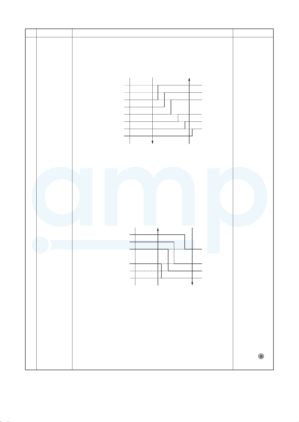
Automatic
capacity control
4
Factory default
Model type SET DATA
Floor standing (standard, concealed, cabinet) 0
Other model 2
1. The outdoor unit determines the operational capacities of indoor units
according to the difference between Ta and Ts.
Cooling Heating
Ta
(˚C)
+2
+1
Ts
–1
SD
SB
S9
S7
S5
S3
S0
Ta
(˚C)
+1
Ts
–1
–2
S3
S5
S7
S9
SB
SD
SF
S0
Ts: Temperature
setting
Ta: Room
temperature
–
23 –
NO. Item Specification outline Remarks
AMP Air Conditioning
www.ampair.co.uk | sales@ampair.co.uk
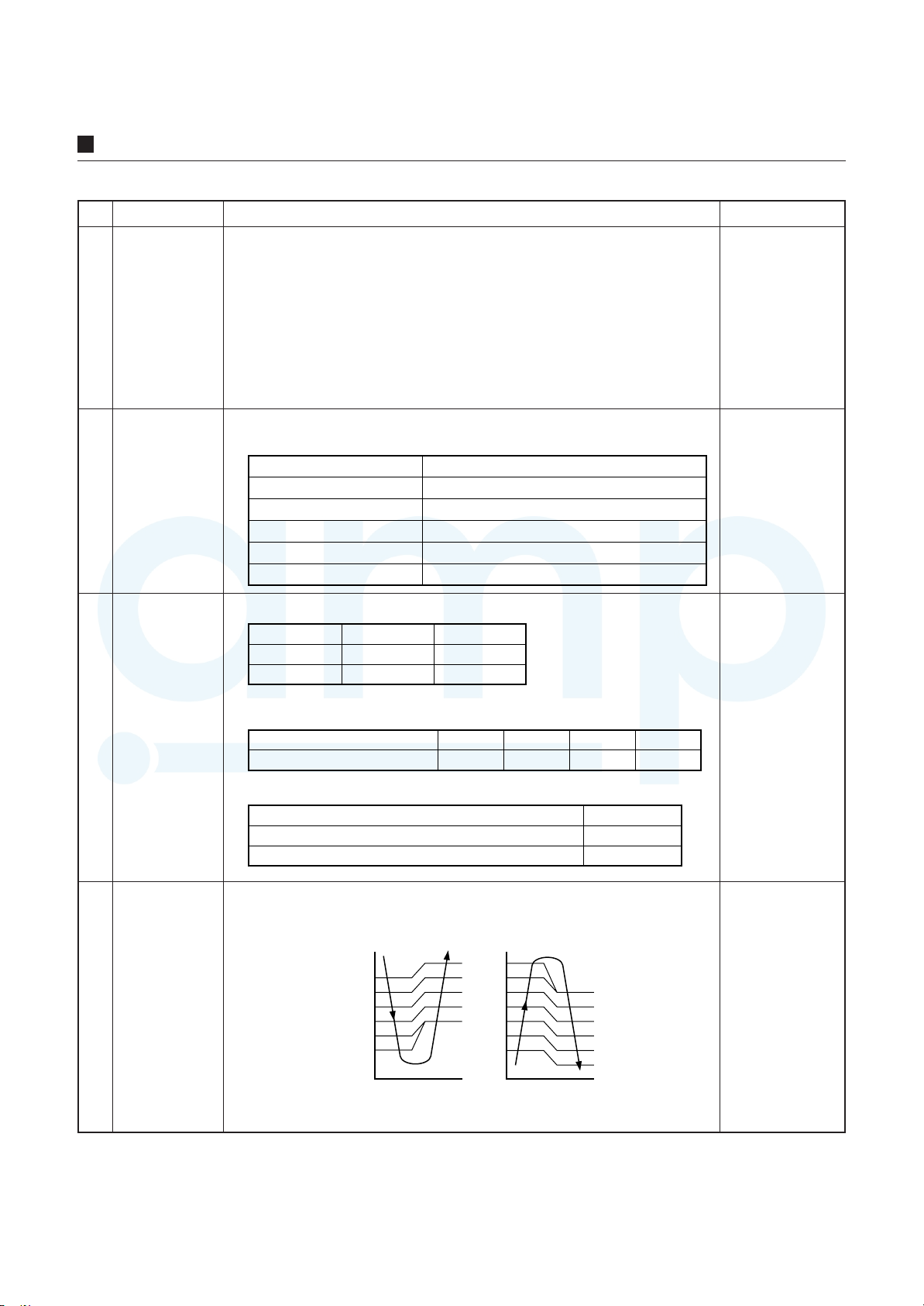
Fan speed
control
1. The fan operates in one of the four speed modes of “HIGH (HH)”, “MED
(H)”, “LOW (L)” and “AUTO” on the basis of a command issued via the
remote controller. (Concealed duct high static pressure type: HH only)
2. In AUTO fan speed mode, the air speed changes according to the
difference between Ta and Ts.
<Cooling>
Ta (˚C)
+3.0
+2.5
+2.0
+1.5
+1.0
+0.5
Tsc
–0.5
HH <HH>
H+ <HH>
H <HH>
L+ <H+>
L <H>
L <H>
L <L+>
A
B
C
D
E
F
G
HH > H+ > H >
L+ > L > UL
or LL
• Control is identical in remote controller thermo and body thermo
operation.
Speed modes shown in < > apply to cooling operation under AUTO air
conditioner operation mode.
• In AUTO fan speed mode, the fan speed remains the same for 3 minutes
each time a speed change occurs.
5
However, a speed change command issued via the remote controller can
override this, and the fan speed changes accordingly.
• At the beginning of cooling operation, a higher speed (steeper downward
temperature gradient) is chosen.
• As long as the temperature difference remains on a boundary line, the
fan speed stays the same.
<Heating>
Ta (˚C)
(–0.5) –1.0
(0) Tsh
(+0.5) +1.0
(+1.0) +2.0
(+1.5) +3.0
(+2.0) +4.0
Figures inside ( ) applies to remote controller thermo operation.
Figures outside ( ) applies to body thermo operation.
Speed modes shown in < > apply to heating operation under AUTO air
conditioner operation mode.
• In AUTO fan speed mode, the fan speed remains the same for 1 minute
each time a speed change occurs.
However, a speed change command issued via the remote controller can
override this, and the fan speed changes accordingly.
• At the beginning of heating operation, a higher speed (steeper upward
temperature gradient) is chosen.
• As long as the temperature difference remains on a boundary line, the
fan speed stays the same.
• When TC2 ≥ 60 °C, the fan speed is raised by one step.
3. If the air conditioner goes thermo OFF during heating operation, the fan
speed drops down to LL (breeze).
L <L+>
L+ <H>
H <H+>
H+
<HH>
HH
<HH>
E
D
C
B
A
DN code “32”
“0000”: Body
thermo
“0001”: Remote
controller thermo
TC2: Indoor heat
exchanger sensor
temperature
“HEATING
STANDBY
displayed
”
–
24 –
NO. Item Specification outline Remarks
AMP Air Conditioning
www.ampair.co.uk | sales@ampair.co.uk
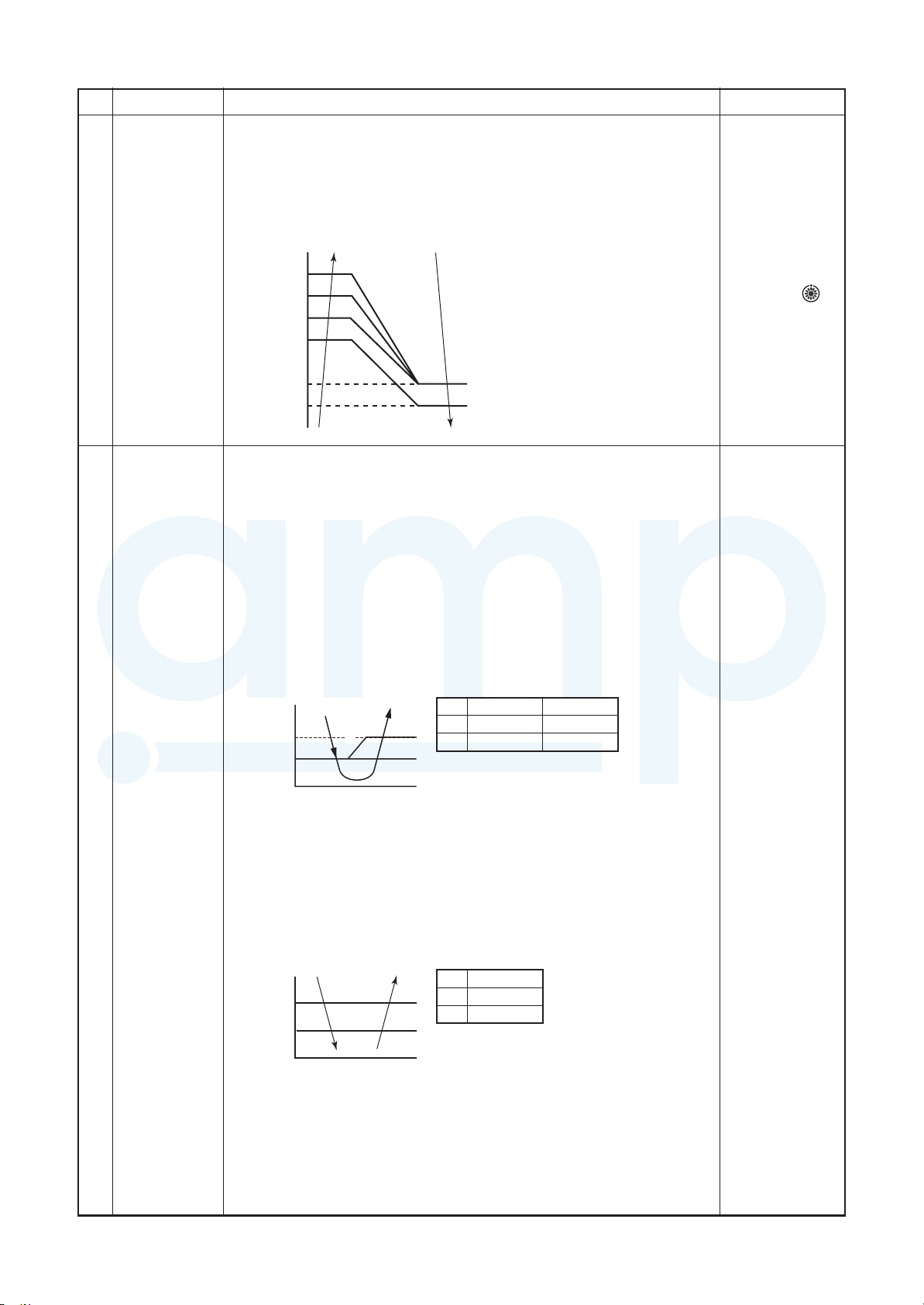
Cold air
discharge
prevention
control
1. In heating operation, the upper limit of the fan tap is set according to the
lower of whichever is the higher between TC2 sensor and TCJ sensor
temperatures, on the one hand, and TC1 sensor temperature, on the
other.
• If the fan continuously operates in zone B for 6 minutes, it automatically
moves into zone C.
• During defrosting, the control point is shifted by +6 °C.
TCJ: Indoor heat
exchanger
sensor
temperature
•In zones D and E,
priority is given
to the remote
controller fan
6
32
30
28
D
C
E
26
20
16
˚C
A zone: OFF
B zone: 26˚C or above and
C zone: 28˚C or above and
D zone: 30˚C or above and
B
E z
A
below 28˚C
breeze
below 30˚C
Lo
below 32˚C
Medium
one: High
w
speed setting.
•In zone A,
“HEATING
STANDBY
is displayed.
”
Freeze
prevention
control (low
temp. release)
7
1. During cooling, the air conditioner is operated in the manner described
below according to the temperature readings of the TC1, TC2 and TCJ
sensors.
• If zone J operation is detected for 5 minutes, the air conditioner is forced
into thermo OFF.
• In zone K, the timer is put on pause, with the current timer count
retained.
• If zone I operation is detected, the timer count is cleared, and the air
conditioner returns to normal operation.
• If continuous zone J operation forces the air conditioner into thermo OFF,
the indoor fan is operated in breeze mode until it moves into zone I.
The control is terminated under the following conditions:
Termination conditions
1) TC1 ≥ 12 °C, TC2 ≥ 12 °C, and TCJ ≥ 12 °C
(˚C)
P1
Q1
P1
I
K
J
a
Q1
TC1
10˚C (5˚C)
0˚C
TC2, TCJ
–10˚C
–14˚C
2) Passage of 20 minutes after stoppage
2. During cooling, the air conditioner is operated in the manner described
below according to the temperature readings of the TC2 and TCJ sensors.
• If zone M operation is detected for 45 minutes, the air conditioner is
forced into thermo OFF.
• In zone N, the timer is put on pause, with the current timer count
retained.
• When the air conditioner goes back into zone M, timer count is resumed
from the retained value.
TC1:
Indoor heat
exchanger
sensor
temperature
(˚C)
P2
Q2
• If zone L operation is detected, the timer count is cleared, and the air
conditioner returns to normal operation.
Reset conditions
1) TC1 ≥ 12 °C, TC2 ≥ 12 °C and TCJ ≥ 12 °C
2) Passage of 20 minutes after stoppage
L
N
M
P2
Q2
TC2, TCJ
5
–2.0
* With models
without TC2,
TC2 is not
part of the
control
parameters.
–
25 –
NO. Item Specification outline Remarks
AMP Air Conditioning
www.ampair.co.uk | sales@ampair.co.uk
Cooling oil
(refrigerant)
recovery control
8
Heating
refrigerant (oil)
recovery
control
9
While the outdoor unit is recovering cooling oil (refrigerant), the indoor
units perform the following control tasks:
[common for operational (cooling thermo ON / thermo OFF / FAN), as
well as nonoperational indoor units]
1)Open the indoor PMV to a certain degree.
2)Engage in recovery control for a specified period of time and return
to normal cooling operation at the end of this period upon
terminating the control.
3)Operate the drain pump throughout the recovery control period and
for about 1 minute after it.
While the outdoor unit is recovering heating refrigerant (oil), the indoor
units perform the following control tasks:
1)Open the indoor PMV to a certain degree.
2)Control the indoor fan according to the operation mode.
[Indoor units operating in heating thermo ON / OFF state]
Let the indoor fan continue operating, but turn it off if the temperature
of the indoor heat exchanger drops.
[Indoor units operating in FAN mode]
Turn off the indoor fan and display “HEATING STANDBY
remote controller.
[Non-operational indoor units]
Keep the indoor fan turned off.
3)Terminate the recovery operation depending on the TC2
temperature reading.
The timing of termination is determined by each indoor unit.
4)Operate the indoor fan and drain pump for about 1 minute after the
termination of the recovery operation. (Applicable to compact 4-way
cassette type and 1- way cassette type)
” on the
• Recovery operation
normally takes
place roughly every
2 hours.
• The opening
position of the
indoor PMV
depending on the
type and capacity
of the indoor unit.
• Recovery
operation
normally takes
place roughly
every hour .
• The opening
position of the
indoor PMV
depending on the
type and capacity
of the indoor unit.
Defrosting
control
10
Short
intermittent
operation
11
compensation
control
Drain pump
control
12
While the outdoor unit is engaged in defrosting control, the indoor units
perform the following control tasks:
1)Open the indoor PMV to a certain degree.
2)Control the indoor fan according to the operation mode.
[Indoor units operating in heating thermo ON / OFF state]
Let the indoor fan continue operating for a while, but turn it off as the
temperature of the indoor heat exchanger drops.
[Indoor units operating in FAN mode]
Let the indoor fan continue operating.
[Non-operational indoor units]
Keep the indoor fan turned off.
3)As defrosting control comes to an end, it gives way to heating
refrigerant (oil) recovery control.
(For control details, see “9. Heating refrigerant (oil) recovery control” abov e.)
1. For 5 minutes after startup, the system is forced to continue operating
even if it reaches the thermo OFF region.
2. However, priority is given to cooling / heating selection, operation
standby, and protective control, so that there is no overriding of
thermo OFF in these cases.
1. During cooling (including DRY operation), the drain pump is operated
at all times.
2. If the float switch is activ ated while the dr ain pump is in operation, the
drain pump continues operating, with the rele vant check code displayed.
3. If the float switch is activ ated while the drain pump is turned off, thermo
OFF is forced on the air conditioner, with the drain pump put into
operation. If the float switch continues to be activated for about 5 minutes,
the drain pump is turned off, with the relevant check code displayed.
• For defrosting
commencement
conditions, see 5
Control Outline “10.
Defrosting control
(reverse defrosting
method)” in SMMS-i
Outdoor Unit
Service Manual
A10-005 above.
• The opening
position of the
indoor PMV
depending on the
type and capacity
of the indoor unit.
Check code [P10]
Elimination of
13
residual heat
1. When the air conditioner is turned off after engaging in heating operation,
the indoor fan is operated for about 30 seconds in “breeze” mode.
–
26 –
NO. Item Specification outline Remarks
AMP Air Conditioning
www.ampair.co.uk | sales@ampair.co.uk
Filter sign
display
(not applicable
to wireless type)
*Provided in
14
the separately
mounted type,
TCB-AX32E2
Operation
standby
Heating standby
15
1. The indoor fan’s cumulative hours of operation are counted, and when
these exceed the prescribed value (2500H), a filter replacement signal
is sent to the remote controller to display a filter sign on it.
2. When a filter reset signal is received from the remote controller, the
timer measuring cumulative hours is cleared. If the prescribed hours
have been exceeded, the hours count is reset, with the sign on the
remote controller display erased.
2500HFilter service life
<Operation standby> .......... Displayed on remote controller
1. When any of the DN codes listed below is displayed
• “P05” - Detection of an open phase in the power supply wiring
• “P10” - Detection of indoor flooding in at least one indoor unit
• “L30” - Detection of an interlock alarm in at least one indoor unit
2. Forced thermo OFF
• “COOL / DRY” operation is unavailable because at least one indoor
unit is operating in “HEAT” mode.
• “HEAT” operation is unavailable because at least one indoor unit is
operating in
“COOL / DRY” mode under pr iority cooling setting (bit 1 of SW11 on
outdoor I/ F P.C. board ON).
3. All indoor units not able to engage in any of the above operations
stand by in thermo OFF state.
4. The indoor fan has been turned off because the system is engaged in
a heat refrigerant (oil) recovery operation.
<Heating standby> .......... Displayed on remote controller
1. Normal thermo OFF
• During heating, the indoor unit goes ther mo OFF as the heating
temperature setting is reached.
2. During heating, the fan rotates at a breeze speed (UL or lower) or
remains stationary to prevent cold air from being discharged
(including defrosting operation).
3.Forced thermo OFF
• “HEAT” operation is unavailable because at least one indoor unit is
operating in
“COOL / DRY” mode under pr iority cooling setting (bit 1 of SW11 on
outdoor I/ F P.C. board ON).
“FILTER
” display ed
• “OPERATION
STANDBY
displayed
No display
provided on
wireless remote
controller
• “HEATING
STANDBY
displayed
”
”
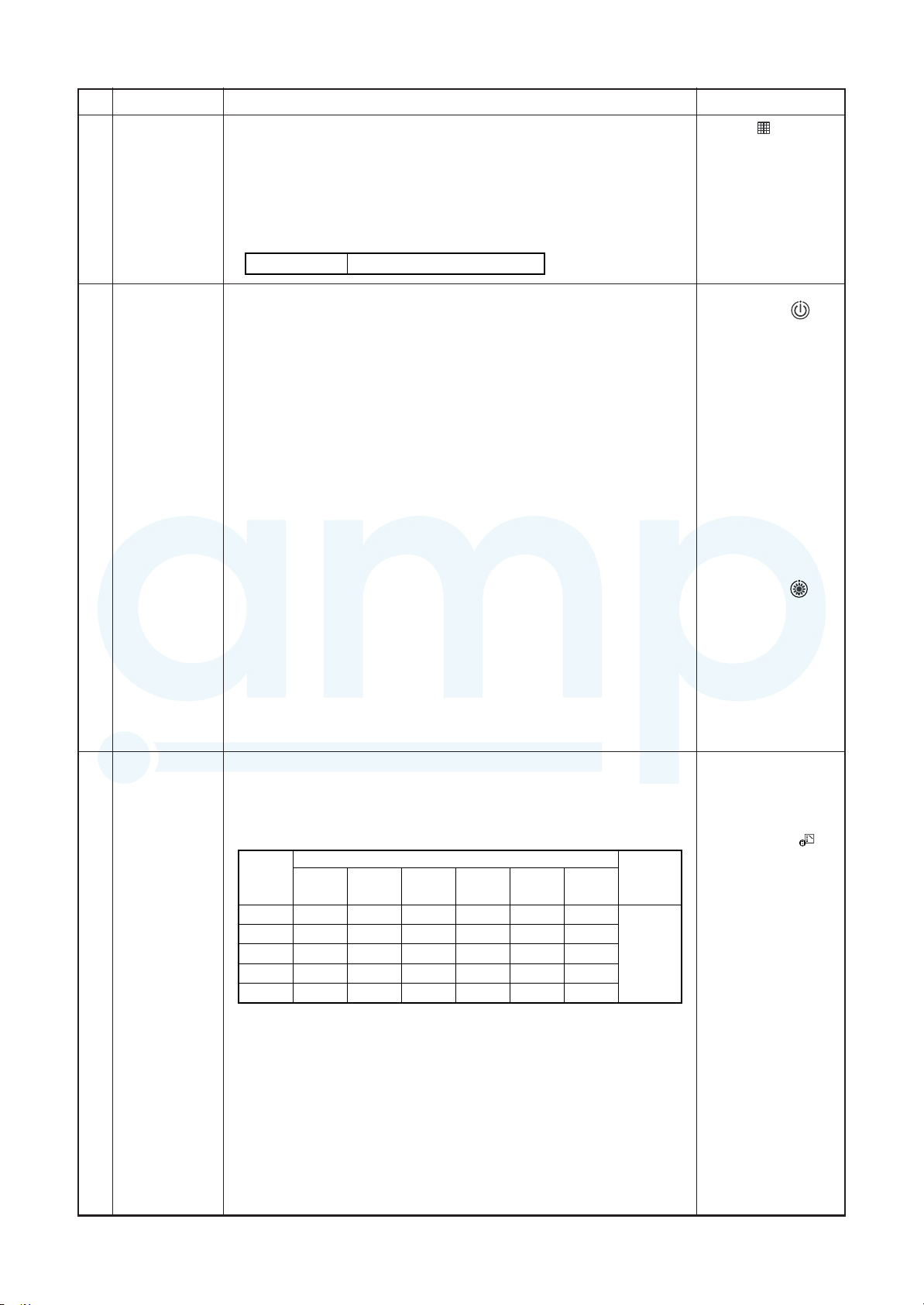
Selection of
central control
mode
16
1. The range of operations that can be performed via an indoor unit
remote controller can be determined through the setting of the central
controller.
2. Setting details
TCC-Link central control
Operation
via TCCLink
Individual
Central 1
Central 2
Central 3
Central 4
(
{
Start / stop
central
control
selection
{
×
×
{
: Accessible × : Inaccessible)
{
Operation on RBC-AMT32E
Operation
mode
selection
{
{
Timer
setting
{
×
×
×
×
×
{
{
Temperature
setting
{
{
×
×
{
Fan speed
setting
{
{
{
{
{
Air flow
direction
setting
{
{
{
{
{
RBC-
AMT32E
display
“CENTRAL
CONTROL
PROGRESS”
• In the case of a
wired remote
controller,
“CENTRAL
CONTROL IN
PROGRESS
”
is displayed (lit up)
while in central
control mode.
• The display blinks
when a control
function
IN
inaccessible to a
remote controller is
chosen.
• A wireless remote
controller has the
same set of control
functions, although
there is no display.
When a control
operation is
performed via a
wireless remote
controller while in
central control
mode, a peep
sound alert (5
times) is provided.
–
27 –
NO. Item Specification outline Remarks
AMP Air Conditioning
www.ampair.co.uk | sales@ampair.co.uk
DC motor 1) When the fan operation has started, positioning of the stator and the
17
Power saving
mode
18
Frequency
fixed
operation
(Test run)
rotor are performed.
(Moves slightly with tap sound)
2) The motor operates according to the command from the indoor
controller.
Notes)
• When the fan rotates while the air conditioner stops due to entering of
outside air, etc, the air conditioner may operate while the fan motor
stops.
• When a fan lock is found, the air conditioner stops, and an error is
displayed.
• If static pressure of the used duct does not match with the setup value of
static pressure, which was decided in the static pressure setting code No.
[5D], the air conditioner may stop or an error code may be displayed.
SAVE
1. Push the
2. The “
3. The requirement capacity ratio is limited to approximately 75 %.
4. If the power saving operation is enabled, the settings are retained
when the operation is stopped, when the mode is changed, or when
the power is reset. The power saving operation will be enabled the
next time the operation starts.
<In case of wired remote controller>
1) When pushing [CHK] button for 4 seconds or more, [TEST] is displayed
on the display screen and the mode enters in Test run mode.
2) Push [ON/OFF] button.
3) Using [MODE] button, set the mode to [COOL] or [HEAT].
• Do not use other mode than [COOL]/[HEAT] mode.
• During test run operation, the temperature cannot be adjusted.
• An error is detected as usual.
• A frequency fixed operation is performed.
4) After the test run, push [ON/OFF] button to stop the operation.
(Display in the display part is same as the procedure in Item 1.)
5) Push [CHK] button to clear the test run mode.
([TEST] display in the display part disappears and the status returns
to the normal stop status.)
button on the remote controller
“ segment lights up on the wired remote controller display.
Check code “P12”
The power saving
operation cannot be
set by the wireless
remote controller or
wired remote
controller of
AMT31E or older.
Command frequency
is approximately [S7]
19
<In case of wireless remote controller>
1) When TEMPORARY button is pushed for 10 seconds or more, “Pi!”
sound is heard and the operation changes to test run. After approx. 3
minutes, a cooling operation starts forcedly.
Check cool air starts blowing. If the operation does not start, check
wiring again.
2) To stop a test operation, push TEMPORARY button once again
(Approx. 1 second).
Check wiring / piping of the indoor and outdoor units in test run.
TEMPORARY button
–
28 –
8. APPLIED CONTROL AND FUNCTIONS
Wired (Simple) heder remote controller (Max. 2 units) Schedule remote controller
Outdoor unit
NU1U2
U1 U2
L
Up to 8 units are connectable.
∗1 It is unavailable to connect the Schedule remote
controller to the simple wired remote controller.
Same as left
#3
(Follower)
A B
AB
Same as left
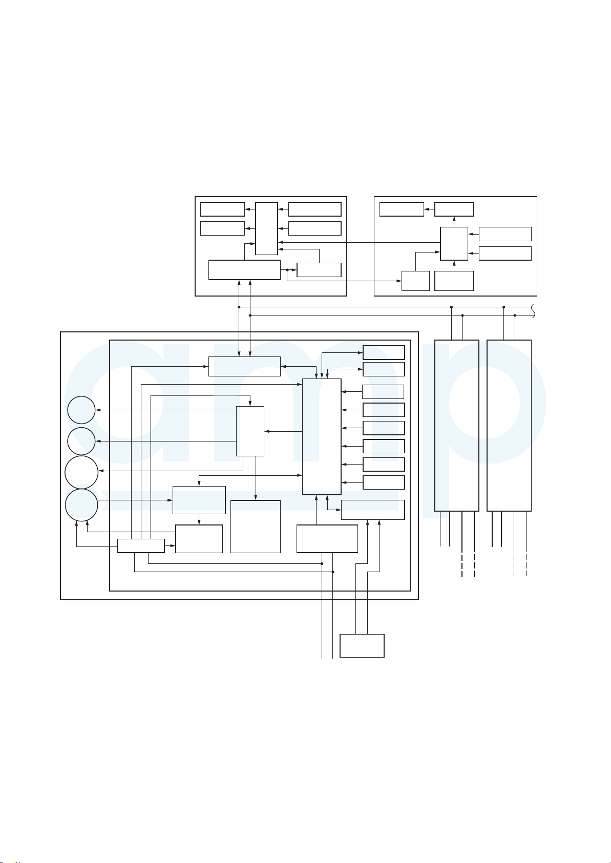
CPU
H8/36109
DC12V
DC5V
DC20V
External
output
Remote controller
communication circuit
Display LCD Function setup
Key switch
CN2
CN1
∗1
CPU
Display LED
Display LCD LCD driver
CPU
Remote controller
communication circuit
Function setup
Key switch
Power circuit
Power circuit
Fan motor
control circuit
CPU
TMP88CH47FG
(TMP88PH47FG)
EEPROM1
EEPROM2
TA sensor
TC1 sensor
TC2 sensor
TCJ sensor
Float input
HA
Run
Alarm
Defrost
Thermo. ON
COOL
HEAT
FAN
BUS
comunication circuit
AC
synchronous
signal input circuit
Power supply
1
∅
, 220-240V, 50Hz
1
∅
, 220V, 60Hz
Power
circuit
Secondary
battery
AMP Air Conditioning
www.ampair.co.uk | sales@ampair.co.uk
(INCLUDING CIRCUIT CONFIGURATION)
8-1. Indoor controller block diagram
8-1-1. In Case of Connection of Wired (Simple) Remote Controller
Indoor unit
#1 (Heder)
Drain
pump
PMV
Flow
Selector
Unit
Indoor
fan motor
DC280V
DC5V
Indoor control P.C. board (MCC-1631)
Driver
DC5V
#2
(Follower)
A B
N
L
Power
Supply
L
Power
Supply
N
–
29 –
Outdoor
unit
Outdoor
unit
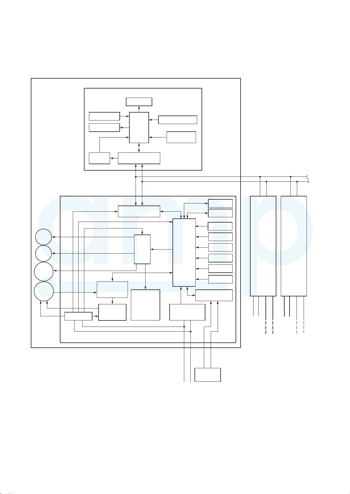
8-1-2. In Case of Connection of Wireless Remote Controller
AMP Air Conditioning
www.ampair.co.uk | sales@ampair.co.uk
Indoor unit
#1 (Heder)
Wireless remote controller
Receiver P.C. board
Display LED
Drain
pump
PMV
Flow
Selector
Unit
Indoor
fan motor
DC280V
Receive circuit
Buzzer
DC5V
Power
circuit
Indoor control P.C. board (MCC-1631)
DC20V
DC5V
DC12V
TMP88CH47FG
(TVP88PH47FG)
Fan motor
Power circuit
control circuit
Remote controller
communication circuit
Remote controller
communication circuit
CPU
CPU
AB
Driver
External
output
Run
Alarm
Defrost
Thermo. ON
COOL
HEAT
FAN
Function setup SW
Temporary
operation SW
CPU
H8/36109
AC
synchronous
signal input circuit
EEPROM2
EEPROM1
TA sensor
TC1 sensor
TC2 sensor
TCJ sensor
Float input
HA
BUS
comunication circuit
#2
(Follower)
A B
Same as left
N
L
Power
Supply
#3
(Follower)
A B
Same as left
N
L
Power
Supply
L
Power supply
∅
, 220-240V, 50Hz
1
1
∅
, 220V, 60Hz
–
30 –
NU1U2
U1 U2
Outdoor unit
Outdoor
unit
Up to 8 units are connectable.
Outdoor
unit
 Loading...