

Toshiba MMU-AP0074YH-E, MMU-AP0094YH-E, MMU-AP0124YH-E, MMU-AP0154SH-E, MMU-AP0184SH-E Service Manual
...
FILE No. A10-033
Revision 1 : Mar., 2012
Revision 2 : Jul., 2013
AIR CONDITIONER (MULTI TYPE)
Revision 3 : Oct., 2014
Revision 4 : Aug., 2015
SERVICE MANUAL
This service manual provides relevant explanations about new indoor unit (4 series). Please refer to
the following service manuals for each indoor units.
Model name:
4-way Cassette Type (MMU-AP∗4HP∗) SVM-13011
2-way Cassette Type (2 series) (MMU-AP∗2WH) A10-007
Ceiling type (MMC-AP∗7HP∗) SVM-13085
Concealed Duct Standard Type (MMD-AP∗6BHP∗) SVM-13087
Concealed Duct High Static Pressure Type (MMD-AP∗6HP∗) SVM-15032
Slim duct (MMD-AP0244SPH, AP0274SPH) A12-005
High-wall Type (4 series) (MMK-AP∗4MH∗) A10-034, SVM-14078
High-wall Type (3 series) (MMK-AP∗3H) SVM-09059
Floor Standing Type (MMF-AP∗6H∗) A10-1420
Fresh Air Intake Indoor Unit Type (MMD-AP∗1HFE) A06-016
Console Type (MML-AP∗4NH) SVM-11012
Air to Air Heat Exchanger with DX Coil Unit (MMD-VN
HEXE∗) A10-022
∗∗∗
Indoor unit
<1-way Cassette Ty pe (YH, SH)>
MMU-AP0074YH-E(-TR)
MMU-AP0094YH-E(-TR)
MMU-AP0124YH-E(-TR)
MMU-AP0154SH-E(-TR)
MMU-AP0184SH-E(-TR)
MMU-AP0244SH-E(-TR)
<Comp act 4-way Cas sette Ty pe>
MMU-AP0056MH-E(-TR)
MMU-AP0054MH-E(-TR)
MMU-AP0074MH-E(-TR)
MMU-AP0094MH-E(-TR)
MMU-AP0124MH-E(-TR)
MMU-AP0154MH-E(-TR)
MMU-AP0184MH-E(-TR)
<Concealed Duct High Static
Pressu re Ty pe>
MMD-AP0184H-E(-TR)
MMD-AP0244H-E(-TR)
MMD-AP0274H-E(-TR)
MMD-AP0364H-E(-TR)
MMD-AP0484H-E(-TR)
MMD-AP0724H-E(-TR)
MMD-AP0964H-E(-TR)
<Ceiling Typ e>
MMC-AP0154H-E(-TR)
MMC-AP0184H-E(-TR)
MMC-AP0244H-E(-TR)
MMC-AP0274H-E(-TR)
MMC-AP0364H-E(-TR)
MMC-AP0484H-E(-TR)
<Floor Standi ng Con ceal ed Type>
MML-AP0074BH-E(-TR)
MML-AP0094BH-E(-TR)
MML-AP0124BH-E(-TR)
MML-AP0154BH-E(-TR)
MML-AP0184BH-E(-TR)
MML-AP0244BH-E(-TR)
<Floor Standi ng Cabinet Ty p e>
MML-AP0074H-E(-TR)
MML-AP0094H-E(-TR)
MML-AP0124H-E(-TR)
MML-AP0154H-E(-TR)
MML-AP0184H-E(-TR)
MML-AP0244H-E(-TR)
<Slim Du ct Ty pe>
MMD-AP0056SPH-E(-TR)
MMD-AP0054SPH-E(-TR)
MMD-AP0074SPH-E(-TR)
MMD-AP0094SPH-E(-TR)
MMD-AP0124SPH-E(-TR)
MMD-AP0154SPH-E(-TR)
MMD-AP0184SPH-E(-TR)
<Flo or Stan di ng Typ e>
MMF-AP0154H-E(-TR)
MMF-AP0184H-E(-TR)
MMF-AP0244H-E(-TR)
MMF-AP0274H-E(-TR)
MMF-AP0364H-E(-TR)
MMF-AP0484H-E(-TR)
MMF-AP0564H-E(-TR)
<Concealed Duc t Standard Ty pe>
MMD-AP0074BH-E(-TR),
MMD-AP0094BH-E(-TR),
MMD-AP0124BH-E(-TR),
MMD-AP0154BH-E(-TR),
MMD-AP0184BH-E(-TR),
MMD-AP0244BH-E(-TR),
MMD-AP0274BH-E(-TR),
MMD-AP0304BH-E(-TR),
MMD-AP0364BH-E(-TR),
MMD-AP0484BH-E(-TR),
MMD-AP0564BH-E(-TR)
PRINTED IN JAPAN, Mar, 2012, ToMo

Contents
Precautions for Safety ................................................................................................ 7
Specifications ............................................................................................................ 13
1 Wiring Diagrams.................................................................................................... 15
1-1. Compact 4-way cassette type .........................................................................................15
1-2. 1-way cassette type (compact type YH) ......................................................................... 16
1-3. 1-way cassette type (SH) ................................................................................................. 17
1-4. Concealed duct standard type ........................................................................................ 18
1-5. Concealed duct high static pressure type ..................................................................... 19
1-6. Slim duct type ................................................................................................................... 21
1-7. Ceiling type ....................................................................................................................... 22
1-8. Floor standing cabinet type ............................................................................................ 23
1-9. Floor standing concealed type ....................................................................................... 24
1-10. Floor standing type .......................................................................................................... 25
2 Parts Rating ........................................................................................................... 26
2-1. Indoor unit......................................................................................................................... 26
3 Refrigerant Cycle Diagram ................................................................................... 30
4 Control Outline ...................................................................................................... 31
5 Applied Control and Functions
(Including Circuit Configuration) ......................................................................... 38
5-1. Indoor controller block diagram ..................................................................................... 38
5-1-1. When main (sub) remote controller connected ................................................................ 38
5-1-2. When wireless remote controller kit connected ............................................................... 40
5-1-3. When both main (sub) remote controller and wireless remote controller kit
connected ............................................................................................................................. 42
5-2. Indoor printed circuit board ............................................................................................ 44
5-3. Optional connector specifications of indoor P.C. board .............................................. 46
5-4. Test operation of indoor unit .......................................................................................... 47
5-5. Method to set indoor unit function DN code ................................................................. 48
5-6. Applied control of indoor unit......................................................................................... 52
6 Troubleshooting .................................................................................................... 68
6-1. Overview ........................................................................................................................... 68
6-2. Troubleshooting method ................................................................................................. 69
6-3. Troubleshooting based on information displayed on remote controller .................... 75
6-4. Check codes displayed on remote controller and SMMS outdoor unit
(7-segment display on I/F board) and locations to be checked................................... 80
6-5. Sensor characteristics ..................................................................................................... 94
– 2 –

7 P.C. Board Exchange Procedures........................................................................ 95
7-1. Replacement of indoor P.C. boards ................................................................................ 95
8 Detachments........................................................................................................ 102
8-1. 1-way cassette (SH)........................................................................................................ 102
8-2. Compact 4-way cassette................................................................................................ 111
8-3. Slim duct ......................................................................................................................... 121
8-4. Concealed duct standard .............................................................................................. 126
8-5. Concealed duct high static pressure ........................................................................... 129
8-6. Ceiling ............................................................................................................................. 130
8-7. Floor standing ................................................................................................................ 138
8-8. Floor standing cabinet................................................................................................... 141
9 Exploded Diagram / Service Parts List ............................................................. 144
9-1. 1-way cassette type (YH) ............................................................................................... 144
9-2. 1-Way cassette type (SH) ............................................................................................... 149
9-3. Compact 4-way cassette type .......................................................................................153
9-4. Slim duct type ................................................................................................................. 159
9-5. Concealed duct standard type ...................................................................................... 165
9-6. Concealed duct high static pressure type ................................................................... 179
9-7. Ceiling type ..................................................................................................................... 187
9-8. Floor standing type ........................................................................................................ 194
9-9. Floor standing concealed type ..................................................................................... 203
9-10. Floor standing cabinet type .......................................................................................... 209
10 Fan Characteristics ........................................................................................... 218
– 3 –

Original instruction
Please read carefully through these instructions that contain important information which complies with the
“Machinery” Directive (Directive 2006/42/EC), and ensure that you understand them.
Generic Denomination: Air Conditioner
Definition of Qualified Installer or Qualified Service Person
The air conditioner must be installed, maintained, repaired and removed by a qualified installer or qualified service
person. When any of these jobs is to be done, ask a qualified installer or qualified service person to do them for you.
A qualified installer or qualified service person is an agent who has the qualifications and knowledge described in
the table below.
evah tsum tnega eht hcihw egdelwonk dna snoitacifilauQtnegA
• The qualified installer is a person who installs, maintains, relocates and removes the air conditioners
made by Toshiba Carrier Corporation. He or she has been trained to install, maintain, relocate and
remove the air conditioners made by Toshiba Carrier Corporation or, alternatively, he or she has been
instructed in such operations by an individual or individuals who have been trained and is thus
thoroughly acquainted with the knowledge related to these operations.
• The qualified installer who is allowed to do the electrical work involved in installation, relocation and
removal has the qualifications pertaining to this electrical work as stipulated by the local laws and
regulations, and he or she is a person who has been trained in matters relating to electrical work on
the air conditioners made by Toshiba Carrier Corporation or, alternatively, he or she has been
instructed in such matters by an individual or individuals who have been trained and is thus thoroughly
Qualified installer
Qualified service
person
acquainted with the knowledge related to this work.
• The qualified installer who is allowed to do the refrigerant handling and piping work involved in
installation, relocation and removal has the qualifications pertaining to this refrigerant handling and
piping work as stipulated by the local laws and regulations, and he or she is a person who has been
trained in matters relating to refrigerant handling and piping work on the air conditioners made by
Toshiba Carrier Corporation or, alternatively, he or she has been instructed in such matters by an
individual or individuals who have been trained and is thus thoroughly acquainted with the knowledge
related to this work.
• The qualified installer who is allowed to work at heights has been trained in matters relating to working
at heights with the air conditioners made by Toshiba Carrier Corporation or, alternatively, he or she
has been instructed in such matters by an individual or individuals who have been trained and is thus
thoroughly acquainted with the knowledge related to this work.
• The qualified service person is a person who installs, repairs, maintains, relocates and removes the
air conditioners made by Toshiba Carrier Corporation. He or she has been trained to install, repair,
maintain, relocate and remove the air conditioners made by Toshiba Carrier Corporation or,
alternatively, he or she has been instructed in such operations by an individual or individuals who have
been trained and is thus thoroughly acquainted with the knowledge related to these operations.
• The qualified service person who is allowed to do the electrical work involved in installation, repair,
relocation and removal has the qualifications pertaining to this electrical work as stipulated by the local
laws and regulations, and he or she is a person who has been trained in matters relating to electrical
work on the air conditioners made by Toshiba Carrier Corporation or, alternatively, he or she has been
instructed in such matters by an individual or individuals who have been trained and is thus thoroughly
acquainted with the knowledge related to this work.
• The qualified service person who is allowed to do the refrigerant handling and piping work involved in
installation, repair, relocation and removal has the qualifications pertaining to this refrigerant handling
and piping work as stipulated by the local laws and regulations, and he or she is a person who has
been trained in matters relating to refrigerant handling and piping work on the air conditioners made
by Toshiba Carrier Corporation or, alternatively, he or she has been instructed in such matters by an
individual or individuals who have been trained and is thus thoroughly acquainted with the knowledge
related to this work.
• The qualified service person who is allowed to work at heights has been trained in matters relating to
working at heights with the air conditioners made by Toshiba Carrier Corporation or, alternatively, he
or she has been instructed in such matters by an individual or individuals who have been trained and
is thus thoroughly acquainted with the knowledge related to this work.
– 4 –
Definition of Protective Gear
When the air conditioner is to be transported, installed, maintained, repaired or removed, wear protective gloves
and ‘safety’ work clothing.
In addition to such normal protective gear, wear the protective gear described below when undertaking the special
work detailed in the table below.
Failure to wear the proper protective gear is dangerous because you will be more susceptible to injury, burns,
electric shocks and other injuries.
nrow raeg evitcetorPnekatrednu kroW
All types of work
Electrical-related work
Work done at heights
(50 cm or more)
Transportation of heavy objects Shoes with additional protective toe cap
Repair of outdoor unit Gloves to provide protection for electricians and from heat
Protective gloves
‘Safety’ working clothing
Gloves to provide protection for electricians and from heat
Insulating shoes
Clothing to provide protection from electric shock
Helmets for use in industry
The important contents concerned to the safety are described on the product itself and on this Service Manual.
Please read this Service Manual after understanding the described items thoroughly in the following contents
(Indications / Illustrated marks), and keep them.
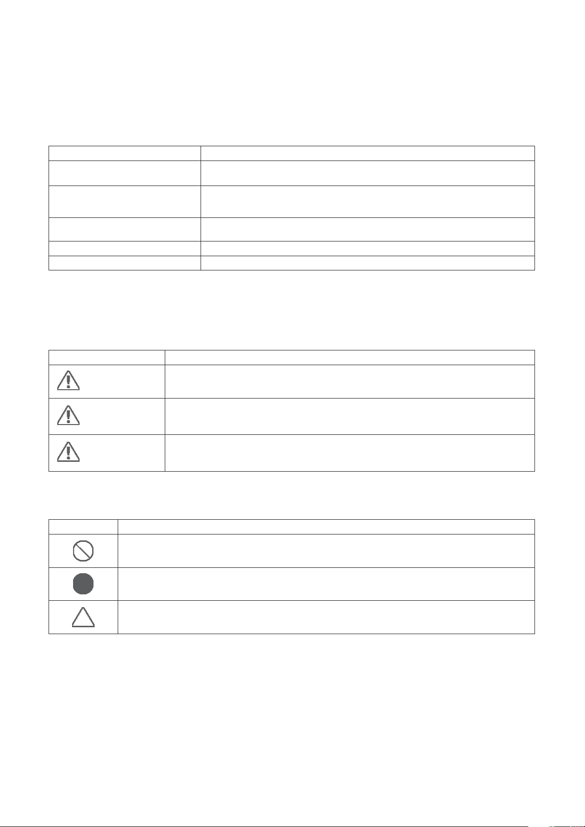
[Explanation of indications]
noitanalpxEnoitacidnI
DANGER
WARNING
CAUTION
Indicates contents assumed that an imminent danger causing a death or serious injury of
the repair engineers and the third parties when an incorrect work has been executed.
Indicates possibilities assumed that a danger causing a death or serious injury of the
repair engineers, the third parties, and the users due to troubles of the product after work
when an incorrect work has been executed.
Indicates contents assumed that an injury or property damage (*) may be caused on the
repair engineers, the third parties, and the users due to troubles of the product after work
when an incorrect work has been executed.
* Property damage: Enlarged damage concerned to property, furniture, and domestic animal / pet
[Explanation of illustrated marks]
noitanalpxEkraM
Indicates prohibited items (Forbidden items to do)
The sentences near an illustrated mark describe the concrete prohibited contents.
Indicates mandatory items (Compulsory items to do)
The sentences near an illustrated mark describe the concrete mandatory contents.
Indicates cautions (Including danger / warning)
The sentences or illustration near or in an illustrated mark describe the concrete cautious contents.
– 5 –
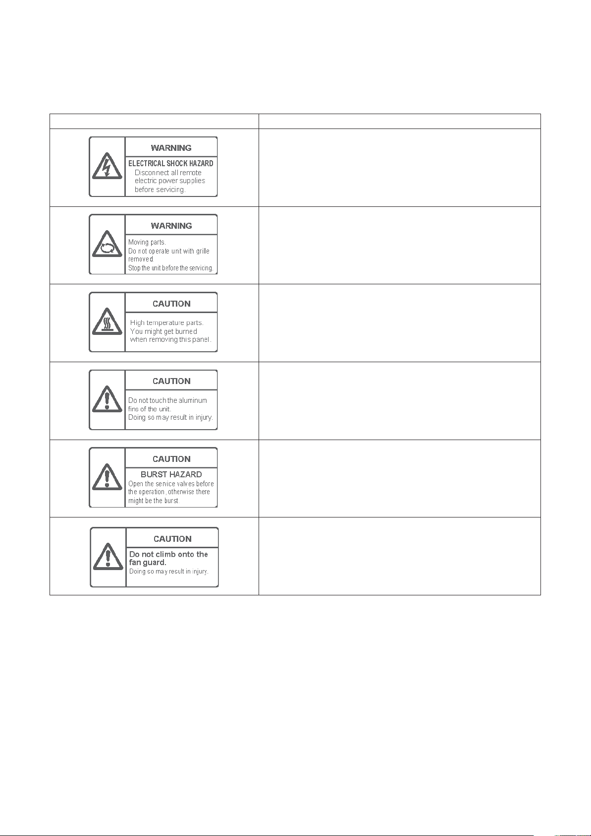
Warning Indications on the Air Conditioner Unit
[Confirmation of warning label on the main unit]
Confirm that labels are indicated on the specified positions
If removing the label during parts replace, stick it as the original.
WARNING
ELECTRICAL SHOCK HAZARD
Disconnect all remote electric power supplies before servicing.
WARNING
Moving parts.
Do not operate unit with grille removed.
Stop the unit before the servicing.
CAUTION
High temperature parts.
You might get burned when removing this panel.
noitpircseDnoitacidni gninraW
CAUTION
Do not touch the aluminium fins of the unit.
Doing so may result in injury.
CAUTION
BURST HAZARD
Open the service valves before the operation, otherwise there might be the
burst.
CAUTION
Do not climb onto the fan guard.
Doing so may result in injury.
– 6 –
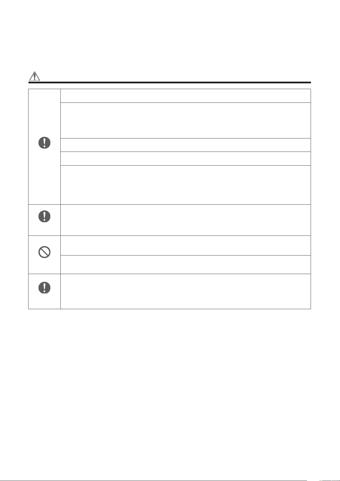
Precautions for Safety
The manufacturer shall not assume any liability for the damage caused by not observing the description of this
manual.
DANGER
Before carrying out the installation, maintenance, repair or removal work, be sure to set the circuit breaker for
both the indoor and outdoor units to the OFF position. Otherwise, electric shocks may result.
Before opening the intake grille of the indoor unit or service panel of the outdoor unit, set the circuit breaker to
the OFF position.
Failure to set the circuit breaker to the OFF position may result in electric shocks through contact with the interior
parts.
Only a qualified installer (*1) or qualified service person (*1) is allowed to remove the intake grille of the indoor
unit or service panel of the outdoor unit and do the work required.
Before starting to repair the outdoor unit fan or fan guard, be absolutely sure to set the circuit breaker to the
OFF position, and place a “Work in progress” sign on the circuit breaker.
Turn off
breaker.
When cleaning the filter or other parts of the indoor unit, set the circuit breaker to OFF without fail, and place a
“Work in progress” sign near the circuit breaker before proceeding with the work.
When you have noticed that some kind of trouble (such as when an error display has appeared, there is a smell
of burning, abnormal sounds are heard, the air conditioner fails to cool or heat or water is leaking) has occurred
in the air conditioner, do not touch the air conditioner yourself but set the circuit breaker to the OFF position,
and contact a qualified service person. Take steps to ensure that the power will not be turned on (by marking
“out of service” near the circuit breaker, for instance) until qualified service person arrives. Continuing to use the
air conditioner in the trouble status may cause mechanical problems to escalate or result in electric shocks or
other failure.
Electric shock
hazard
Prohibition
Stay on
protection
When you access inside of the service panel to repair electric parts, wait for about five minutes after turning off
the breaker. Do not start repairing immediately.Otherwise you may get electric shock by touching terminals of
high-voltage capacitors. Natural discharge of the capacitor takes about five minutes.
Place a “Work in progress” sign near the circuit breaker while the installation, maintenance, repair or removal
work is being carried out.
There is a danger of electric shocks if the circuit breaker is set to ON by mistake.
Before operating the air conditioner after having completed the work, check that the electrical parts box cover
of the indoor unit and service panel of the outdoor unit are closed, and set the circuit breaker to the ON position.
You may receive an electric shock if the power is turned on without first conducting these checks.
If, in the course of carrying out repairs, it becomes absolutely necessary to check out the electrical parts with
the electrical parts box cover of one or more of the indoor units and the service panel of the outdoor unit
removed in order to find out exactly where the trouble lies, wear insulated heat-resistant gloves, insulated boots
and insulated work overalls, and take care to avoid touching any live parts.
You may receive an electric shock if you fail to heed this warning. Only qualified service person (*1) is allowed
to do this kind of work.
– 7 –
WARNING
General
Check earth
wires.
Before starting to repair the air conditioner, read carefully through the Service Manual, and repair the air
conditioner by following its instructions.
Only qualified service person (*1) is allowed to repair the air conditioner.
Repair of the air conditioner by unqualified person may give rise to a fire, electric shocks, injury, water leaks and
/ or other problems.
Do not use any refrigerant different from the one specified for complement or replacement.
Otherwise, abnormally high pressure may be generated in the refrigeration cycle, which may result in a failure
or explosion of the product or an injury to your body.
Only a qualified installer (*1) or qualified service person (*1) is allowed to carry out the electrical work of the air
conditioner.
Under no circumstances must this work be done by an unqualified individual since failure to carry out the work
properly may result in electric shocks and / or electrical leaks.
When transporting the air conditioner, wear shoes with protective toe caps, protective gloves and other
protective clothing.
When connecting the electrical wires, repairing the electrical parts or undertaking other electrical jobs, wear
gloves to provide protection for electricians and from heat, insulating shoes and clothing to provide protection
from electric shocks.
Failure to wear this protective gear may result in electric shocks.
Electrical wiring work shall be conducted according to law and regulation in the community and installation
manual. Failure to do so may result in electrocution or short circuit.
Only a qualified installer (*1) or qualified service person (*1) is allowed to undertake work at heights using a
stand of 50 cm or more or to remove the intake grille of the indoor unit to undertake work.
When working at heights, use a ladder which complies with the ISO 14122 standard, and follow the procedure
in the ladder’s instructions.
Also wear a helmet for use in industry as protective gear to undertake the work.
When working at heights, put a sign in place so that no-one will approach the work location, before proceeding
with the work.
Parts and other objects may fall from above, possibly injuring a person below.
When executing address setting, test run, or troubleshooting through the checking window on the electric parts
box, put on insulated gloves to provide protection from electric shock. Otherwise you may receive an electric
shock.
Do not touch the aluminum fin of the outdoor unit.
You may injure yourself if you do so. If the fin must be touched for some reason, first put on protective gloves
and safety work clothing, and then proceed.
Do not climb onto or place objects on top of the outdoor unit.
You may fall or the objects may fall off of the outdoor unit and result in injury.
When transporting the air conditioner, wear shoes with additional protective toe caps.
When transporting the air conditioner, do not take hold of the bands around the packing carton.
You may injure yourself if the bands should break.
Be sure that a heavy unit (10 kg or heavier) such as a compressor is carried by two persons.
This air conditioner has passed the pressure test as specified in IEC 60335-2-40 Annex EE.
Before troubleshooting or repair work, check the earth wire is connected to the earth terminals of the main unit,
otherwise an electric shock is caused when a leak occurs.If the earth wire is not correctly connected, contact
an electric engineer for rework.
After completing the repair or relocation work, check that the ground wires are connected properly.
Be sure to connect earth wire. (Grounding work) Incomplete grounding causes an electric shock.
Do not connect ground wires to gas pipes, water pipes, and lightning rods or ground wires for telephone wires.
Prohibition of
modification.
Use specified
parts.
Do not modify the products.Do not also disassemble or modify the parts.
It may cause a fire, electric shock or injury.
When any of the electrical parts are to be replaced, ensure that the replacement parts satisfy the specifications
given in the Service Manual (or use the parts contained on the parts list in the Service Manual).
Use of any parts which do not satisfy the required specifications may give rise to electric shocks, smoking and
/ or a fire.
– 8 –
Do not bring a
child close to
the
equipment.
Insulating
measures
No fire
Refrigerant
If, in the course of carrying out repairs, it becomes absolutely necessary to check out the electrical parts with
the electrical parts box cover of one or more of the indoor units and the service panel of the outdoor unit
removed in order to find out exactly where the trouble lies, put a sign in place so that no-one will approach the
work location before proceeding with the work. Third-party individuals may enter the work site and receive
electric shocks if this warning is not heeded.
Connect the cut-off lead wires with crimp contact, etc., put the closed end side upward and then apply a watercut method, otherwise a leak or production of fire is caused at the users’ side.
When performing repairs using a gas burner, replace the refrigerant with nitrogen gas because the oil that coats
the pipes may otherwise burn.
When repairing the refrigerating cycle, take the following measures.
1) Be attentive to fire around the cycle. When using a gas stove, etc., be sure to put out fire before work;
otherwise the oil mixed with refrigerant gas may catch fire.
2) Do not use a welder in the closed room. When using it without ventilation, carbon monoxide poisoning may
be caused.
3) Do not bring inflammables close to the refrigerant cycle, otherwise fire of the welder may catch the
inflammables.
The refrigerant used by this air conditioner is the R410A.
Check the used refrigerant name and use tools and materials of the parts which match with it.
For the products which use R410A refrigerant, the refrigerant name is indicated at a position on the outdoor unit
where is easy to see. To prevent miss-charging, the route of the service port is changed from one of the former
R22.
For an air conditioner which uses R410A, never use other refrigerant than R410A. For an air conditioner which
uses other refrigerant (R22, etc.), never use R410A.
If different types of refrigerant are mixed, abnormal high pressure generates in the refrigerating cycle and an
injury due to breakage may be caused.
When the air conditioner has been installed or relocated, follow the instructions in the Installation Manual and
purge the air completely so that no gases other than the refrigerant will be mixed in the refrigerating cycle.
Failure to purge the air completely may cause the air conditioner to malfunction.
Do not charge refrigerant additionally. If charging refrigerant additionally when refrigerant gas leaks, the
refrigerant composition in the refrigerating cycle changes resulted in change of air conditioner characteristics or
refrigerant over the specified standard amount is charged and an abnormal high pressure is applied to the inside
of the refrigerating cycle resulted in cause of breakage or injury. Therefore if the refrigerant gas leaks, recover
the refrigerant in the air conditioner, execute vacuuming, and then newly recharge the specified amount of liquid
refrigerant.
In this time, never charge the refrigerant over the specified amount.
When recharging the refrigerant in the refrigerating cycle, do not mix the refrigerant or air other than R410A into
the specified refrigerant. If air or others is mixed with the refrigerant, abnormal high pressure generates in the
refrigerating cycle resulted in cause of injury due to breakage.
After installation work, check the refrigerant gas does not leak. If the refrigerant gas leaks in the room,
poisonous gas generates when gas touches to fire such as fan heater, stove or cocking stove though the
refrigerant gas itself is innocuous.
Never recover the refrigerant into the outdoor unit. When the equipment is moved or repaired, be sure to recover
the refrigerant with recovering device.
The refrigerant cannot be recovered in the outdoor unit; otherwise a serious accident such as breakage or injury
is caused.
Assembly /
Wiring
Insulator
check
Ventilation
After repair work, surely assemble the disassembled parts, and connect and lead the removed wires as before.
Perform the work so that the cabinet or panel does not catch the inner wires.
If incorrect assembly or incorrect wire connection was done, a disaster such as a leak or fire is caused at user’s
side.
After the work has finished, be sure to use an insulation tester set (500 V Megger) to check the resistance is
1 M
or more between the charge section and the non-charge metal section (Earth position).
If the resistance value is low, a disaster such as a leak or electric shock is caused at user’s side.
When the refrigerant gas leaks during work, execute ventilation.
If the refrigerant gas touches to a fire, poisonous gas generates. A case of leakage of the refrigerant and the
closed room full with gas is dangerous because a shortage of oxygen occurs. Be sure to execute ventilation.
– 9 –
Compulsion
Check after
repair
Do not
operate the
unit with the
valve closed.
Check after
reinstallation
Cooling check
When the refrigerant gas leaks, find up the leaked position and repair it surely.
If the leaked position cannot be found up and the repair work is interrupted, pump-down and tighten the service
valve, otherwise the refrigerant gas may leak into the room.
The poisonous gas generates when gas touches to fire such as fan heater, stove or cocking stove though the
refrigerant gas itself is innocuous.
When installing equipment which includes a large amount of charged refrigerant such as a multi air conditioner
in a sub-room, it is necessary that the density does not the limit even if the refrigerant leaks.
If the refrigerant leaks and exceeds the limit density, an accident of shortage of oxygen is caused.
Tighten the flare nut with a torque wrench in the specified manner.
Excessive tighten of the flare nut may cause a crack in the flare nut after a long period, which may result in
refrigerant leakage.
Nitrogen gas must be used for the airtight test.
The charge hose must be connected in such a way that it is not slack.
For the installation / moving / reinstallation work, follow to the Installation Manual.
If an incorrect installation is done, a trouble of the refrigerating cycle, water leak, electric shock or fire is caused.
Once the repair work has been completed, check for refrigerant leaks, and check the insulation resistance and
water drainage.
Then perform a trial run to check that the air conditioner is running properly.
After repair work has finished, check there is no trouble. If check is not executed, a fire, electric shock or injury
may be caused. For a check, turn off the power breaker.
After repair work (installation of front panel and cabinet) has finished, execute a test run to check there is no
generation of smoke or abnormal sound.
If check is not executed, a fire or an electric shock is caused. Before test run, install the front panel and cabinet.
Be sure to fix the screws back which have been removed for installation or other purposes.
Check the following matters before a test run after repairing piping.
• Connect the pipes surely and there is no leak of refrigerant.
• The valve is opened.
Running the compressor under condition that the valve closes causes an abnormal high pressure resulted in
damage of the parts of the compressor and etc. and moreover if there is leak of refrigerant at connecting section
of pipes, the air is sucked and causes further abnormal high pressure resulted in burst or injury.
Only a qualified installer (*1) or qualified service person (*1) is allowed to relocate the air conditioner. It is
dangerous for the air conditioner to be relocated by an unqualified individual since a fire, electric shocks, injury,
water leakage, noise and / or vibration may result.
Check the following items after reinstallation.
1) The earth wire is correctly connected.
2) The power cord is not caught in the product.
3) There is no inclination or unsteadiness and the installation is stable.
If check is not executed, a fire, an electric shock or an injury is caused.
When carrying out the pump-down work shut down the compressor before disconnecting the refrigerant pipe.
Disconnecting the refrigerant pipe with the service valve left open and the compressor still operating will cause
air, etc. to be sucked in, raising the pressure inside the refrigeration cycle to an abnormally high level, and
possibly resulting in reputing, injury, etc.
When the service panel of the outdoor unit is to be opened in order for the compressor or the area around this
part to be repaired immediately after the air conditioner has been shut down, set the circuit breaker to the OFF
position, and then wait at least 10 minutes before opening the service panel.
If you fail to heed this warning, you will run the risk of burning yourself because the compressor pipes and other
parts will be very hot to the touch. In addition, before proceeding with the repair work, wear the kind of insulated
heat-resistant gloves designed to protect electricians.
Take care not to get burned by compressor pipes or other parts when checking the cooling cycle while running
the unit as they get heated while running. Be sure to put on gloves providing protection for electric shock and
heat.
When the service panel of the outdoor unit is to be opened in order for the fan motor, reactor, inverter or the
areas around these parts to be repaired immediately after the air conditioner has been shut down, set the circuit
breaker to the OFF position, and then wait at least 10 minutes before opening the service panel.
If you fail to heed this warning, you will run the risk of burning yourself because the fan motor, reactor, inverter
heat sink and other parts will be very hot to the touch.
In addition, before proceeding with the repair work, wear the kind of insulated heat-resistant gloves designed to
protect electricians.
– 10 –
Only a qualified installer (*1) or qualified service person (*1) is allowed to install the air conditioner. If the air
conditioner is installed by an unqualified individual, a fire, electric shocks, injury, water leakage, noise and / or
vibration may result.
Before starting to install the air conditioner, read carefully through the Installation Manual, and follow its
instructions to install the air conditioner.
Be sure to use the company-specified products for the separately purchased parts. Use of non-specified
products may result in fire, electric shock, water leakage or other failure. Have the installation performed by a
qualified installer.
Do not supply power from the power terminal block equipped on the outdoor unit to another outdoor unit.
Capacity overflow may occur on the terminal block and may result in fire.
Do not install the air conditioner in a location that may be subject to a risk of expire to a combustible gas.
If a combustible gas leaks and becomes concentrated around the unit, a fire may occur.
Installation
Install the indoor unit at least 2.5 m above the floor level since otherwise the users may injure themselves or
receive electric shocks if they poke their fingers or other objects into the indoor unit while the air conditioner is
running.
Install a circuit breaker that meets the specifications in the installation manual and the stipulations in the local
regulations and laws.
Install the circuit breaker where it can be easily accessed by the qualified service person (*1).
If you install the unit in a small room, take appropriate measures to prevent the refrigerant from exceeding the
limit concentration even if it leaks. Consult the dealer from whom you purchased the air conditioner when you
implement the measures. Accumulation of highly concentrated refrigerant may cause an oxygen deficiency
accident.
Do not place any combustion appliance in a place where it is directly exposed to the wind of air conditioner,
otherwise it may cause imperfect combustion.
Explanations given to user
If you have discovered that the fan grille is damaged, do not approach the outdoor unit but set the circuit breaker
to the OFF position, and contact a qualified service person to have the repairs done.
Do not set the circuit breaker to the ON position until the repairs are completed.
Relocation
• Only a qualified installer (*1) or qualified service person (*1) is allowed to relocate the air conditioner.
It is dangerous for the air conditioner to be relocated by an unqualified individual since a fire, electric shocks,
injury, water leakage, noise and / or vibration may result.
• When carrying out the pump-down work shut down the compressor before disconnecting the refrigerant pipe.
Disconnecting the refrigerant pipe with the service valve left open and the compressor still operating will cause
air, etc. to be sucked in, raising the pressure inside the refrigeration cycle to an abnormally high level, and
possibly resulting in reputing, injury, etc.
(*1) Refer to the “Definition of Qualified Installer or Qualified Service Person”
– 11 –

Declaration of Conformity
Manufacturer: Toshiba Carrier Corporation
Authorized Representative /
TCF holder:
Hereby declares that the machinery described below:
Generic Denomination: Air Conditioner
Model / type: Indoor unit
336 Tadehara, Fuji-shi, Shizuoka-ken 416-8521 JAPAN
Nick Ball
Toshiba EMEA Engineering Director
Toshiba Carrier UK Ltd.
Porsham Close, Belliver Industrial Estate,
PLYMOUTH, Devon, PL6 7DB.
United Kingdom
<1-way Cassette Type (YH, SH)>
MMU-AP0074YH-E(TR), MMU-AP0094YH-E(TR), MMU-AP0124YH-E(TR),
MMU-AP0154SH-E(TR), MMU-AP0184SH-E(TR), MMU-AP0244SH-E(TR)
<Compact 4-way Cassette Type>
MMU-AP0056MH-E(TR), MMU-AP0054MH-E(TR), MMU-AP0074MH-E(TR), MMU-AP0094MH-E(TR),
MMU-AP0124MH-E(TR), MMU-AP0154MH-E(TR), MMU-AP0184MH-E(TR)
<Slim Duct Type>
MMD-AP0056SPH-E(TR), MMD-AP0054SPH-E(TR), MMD-AP0074SPH-E(TR), MMD-AP0094SPH-E(TR),
MMD-AP0124SPH-E(TR), MMD-AP0154SPH-E(TR), MMD-AP0184SPH-E(TR)
<Concealed Duct Standard Type>
MMD-AP0074BH-E(TR), MMD-AP0094BH-E(TR), MMD-AP0124BH-E(TR), MMD-AP0154BH-E(TR),
MMD-AP0184BH-E(TR), MMD-AP0244BH-E(TR), MMD-AP0274BH-E(TR), MMD-AP0304BH-E(TR),
MMD-AP0364BH-E(TR), MMD-AP0484BH-E(TR), MMD-AP0564BH-E(TR)
<Concealed Duct High Static Pressure Type>
MMD-AP0184H-E(TR), MMD-AP0244H-E(TR), MMD-AP0274H-E(TR), MMD-AP0364H-E(TR),
MMD-AP0484H-E(TR), MMD-AP0724H-E(TR), MMD-AP0964H-E(TR)
<Ceiling Type>
MMC-AP0154H-E(TR), MMC-AP0184H-E(TR), MMC-AP0244H-E(TR), MMC-AP0274H-E(TR),
MMC-AP0364H-E(TR), MMC-AP0484H-E(TR)
<Floor Standing Type>
MMF-AP0154H-E(TR), MMF-AP0184H-E(TR), MMF-AP0244H-E(TR), MMF-AP0274H-E(TR),
MMF-AP0364H-E(TR), MMF-AP0484H-E(TR), MMF-AP0564H-E(TR)
<Floor Standing Concealed Type>
MML-AP0074BH-E(TR), MML-AP0094BH-E(TR), MML-AP0124BH-E(TR), MML-AP0154BH-E(TR),
MML-AP0184BH-E(TR), MML-AP0244BH-E(TR)
<Floor Standing Cabinet Type>
MML-AP0074H-E(TR), MML-AP0094H-E(TR), MML-AP0124H-E(TR), MML-AP0154H-E(TR),
MML-AP0184H-E(TR), MML-AP0244H-E(TR)
Commercial name: Super Modular Multi System Air Conditioner
Complies with the provisions of the “Machinery” Directive (Directive 2006/42/EC) and the regulations transposing into national law
Super Heat Recovery Multi System Air Conditioner
MiNi-Super Modular Multi System Air Conditioner (MiNi-SMMS series)
NOTE
This declaration becomes invalid if technical or operational modifications are introduced without the manufacturer’s
consent.
– 12 –

Specifications
Model
MMU-AP0056MH-E
MMU-AP0054MH-E
MMU-AP0074MH-E
MMU-AP0094MH-E
MMU-AP0124MH-E
MMU-AP0154MH-E
MMU-AP0184MH-E
MMU-AP0074YH-E
MMU-AP0094YH-E
MMU-AP0124YH-E
MMU-AP0154SH-E
MMU-AP0184SH-E
MMU-AP0244SH-E
MMD-AP0074BH-E
MMD-AP0094BH-E
MMD-AP0124BH-E
MMD-AP0154BH-E
MMD-AP0184BH-E
MMD-AP0244BH-E
MMD-AP0274BH-E
MMD-AP0304BH-E
MMD-AP0364BH-E
MMD-AP0484BH-E
MMD-AP0564BH-E
MMD-AP0184H-E
MMD-AP0244H-E
MMD-AP0274H-E
MMD-AP0364H-E
MMD-AP0484H-E
MMD-AP0724H-E
MMD-AP0964H-E
MMD-AP0056SPH-E
MMD-AP0054SPH-E
MMD-AP0074SPH-E
MMD-AP0094SPH-E
MMD-AP0124SPH-E
MMD-AP0154SPH-E
MMD-AP0184SPH-E
MMC-AP0154H-E
MMC-AP0184H-E
MMC-AP0244H-E
MMC-AP0274H-E
MMC-AP0364H-E
MMC-AP0484H-E
MML-AP0074H-E
MML-AP0094H-E
MML-AP0124H-E
MML-AP0154H-E
MML-AP0184H-E
MML-AP0244H-E
MML-AP0074BH-E
MML-AP0094BH-E
MML-AP0124BH-E
MML-AP0154BH-E
MML-AP0184BH-E
MML-AP0244BH-E
MMF-AP0154H-E
MMF-AP0184H-E
MMF-AP0244H-E
MMF-AP0274H-E
MMF-AP0364H-E
MMF-AP0484H-E
MMF-AP0564H-E
Sound power level (dBA)
Cooling Heating
Main unit (Ceiling panel)
∗∗
∗
∗
∗
∗
∗
∗
∗
∗
∗
∗
∗
∗
∗
∗
∗
∗
∗
∗
∗
∗
∗
∗
∗
∗
∗
∗
∗
∗
∗
70
∗
∗
∗
∗
∗
∗
∗
∗
∗
∗
∗
∗
∗
∗
∗
∗
∗
∗
∗
∗
∗
∗
∗
∗
∗
∗
∗
∗
∗
70
∗∗
∗
∗
∗
∗
∗
∗
∗
∗
∗
∗
∗
∗
∗
∗
∗
∗
∗
∗
∗
∗
∗
∗
∗
∗
∗
∗
∗
∗
∗
72
72
∗
∗
∗
∗
∗
∗
∗
∗
∗
∗
∗
∗
∗
∗
∗
∗
∗
∗
∗
∗
∗
∗
∗
∗
∗
∗
∗
∗
∗
72
72
Weight (kg)
17 (3)
17 (3)
17 (3)
17 (3)
17 (3)
17 (3)
17 (3)
22 (3.5)
22 (3.5)
22 (3.5)
21 (5.5)
21 (5.5)
22 (5.5)
28
28
28
32
32
43
43
43
55
55
55
50
52
52
56
67
160
160
22
22
22
22
22
23
23
22
22
26
26
34
34
37
37
37
37
40
40
21
21
21
29
29
29
48
48
49
49
65
65
65
– 13 –
Model
MMU-AP0056MH-TR
MMU-AP0054MH-TR
MMU-AP0074MH-TR
MMU-AP0094MH-TR
MMU-AP0124MH-TR
MMU-AP0154MH-TR
MMU-AP0184MH-TR
MMU-AP0074YH-TR
MMU-AP0094YH-TR
MMU-AP0124YH-TR
MMU-AP0154SH-TR
MMU-AP0184SH-TR
MMU-AP0244SH-TR
MMD-AP0074BH-TR
MMD-AP0094BH-TR
MMD-AP0124BH-TR
MMD-AP0154BH-TR
MMD-AP0184BH-TR
MMD-AP0244BH-TR
MMD-AP0274BH-TR
MMD-AP0304BH-TR
MMD-AP0364BH-TR
MMD-AP0484BH-TR
MMD-AP0564BH-TR
MMD-AP0184H-TR
MMD-AP0244H-TR
MMD-AP0274H-TR
MMD-AP0364H-TR
MMD-AP0484H-TR
MMD-AP0724H-TR
MMD-AP0964H-TR
MMD-AP0056SPH-TR
MMD-AP0054SPH-TR
MMD-AP0074SPH-TR
MMD-AP0094SPH-TR
MMD-AP0124SPH-TR
MMD-AP0154SPH-TR
MMD-AP0184SPH-TR
MMC-AP0154H-TR
MMC-AP0184H-TR
MMC-AP0244H-TR
MMC-AP0274H-TR
MMC-AP0364H-TR
MMC-AP0484H-TR
MML-AP0074H-TR
MML-AP0094H-TR
MML-AP0124H-TR
MML-AP0154H-TR
MML-AP0184H-TR
MML-AP0244H-TR
MML-AP0074BH-TR
MML-AP0094BH-TR
MML-AP0124BH-TR
MML-AP0154BH-TR
MML-AP0184BH-TR
MML-AP0244BH-TR
MMF-AP0154H-TR
MMF-AP0184H-TR
MMF-AP0244H-TR
MMF-AP0274H-TR
MMF-AP0364H-TR
MMF-AP0484H-TR
MMF-AP0564H-TR
Sound power level (dBA)
Cooling Heating
Main unit (Ceiling panel)
∗∗
∗
∗
∗
∗
∗
∗
∗
∗
∗
∗
∗
∗
∗
∗
∗
∗
∗
∗
∗
∗
∗
∗
∗
∗
∗
∗
∗
∗
∗
70
∗
∗
∗
∗
∗
∗
∗
∗
∗
∗
∗
∗
∗
∗
∗
∗
∗
∗
∗
∗
∗
∗
∗
∗
∗
∗
∗
∗
∗
70
∗∗
∗
∗
∗
∗
∗
∗
∗
∗
∗
∗
∗
∗
∗
∗
∗
∗
∗
∗
∗
∗
∗
∗
∗
∗
∗
∗
∗
∗
∗
72
72
∗
∗
∗
∗
∗
∗
∗
∗
∗
∗
∗
∗
∗
∗
∗
∗
∗
∗
∗
∗
∗
∗
∗
∗
∗
∗
∗
∗
∗
72
72
Weight (kg)
17 (3)
17 (3)
17 (3)
17 (3)
17 (3)
17 (3)
17 (3)
22 (3.5)
22 (3.5)
22 (3.5)
21 (5.5)
21 (5.5)
22 (5.5)
28
28
28
32
32
43
43
43
55
55
55
50
52
52
56
67
160
160
22
22
22
22
22
23
23
22
22
26
26
34
34
37
37
37
37
40
40
21
21
21
29
29
29
48
48
49
49
65
65
65
– 14 –
1 Wiring Diagrams
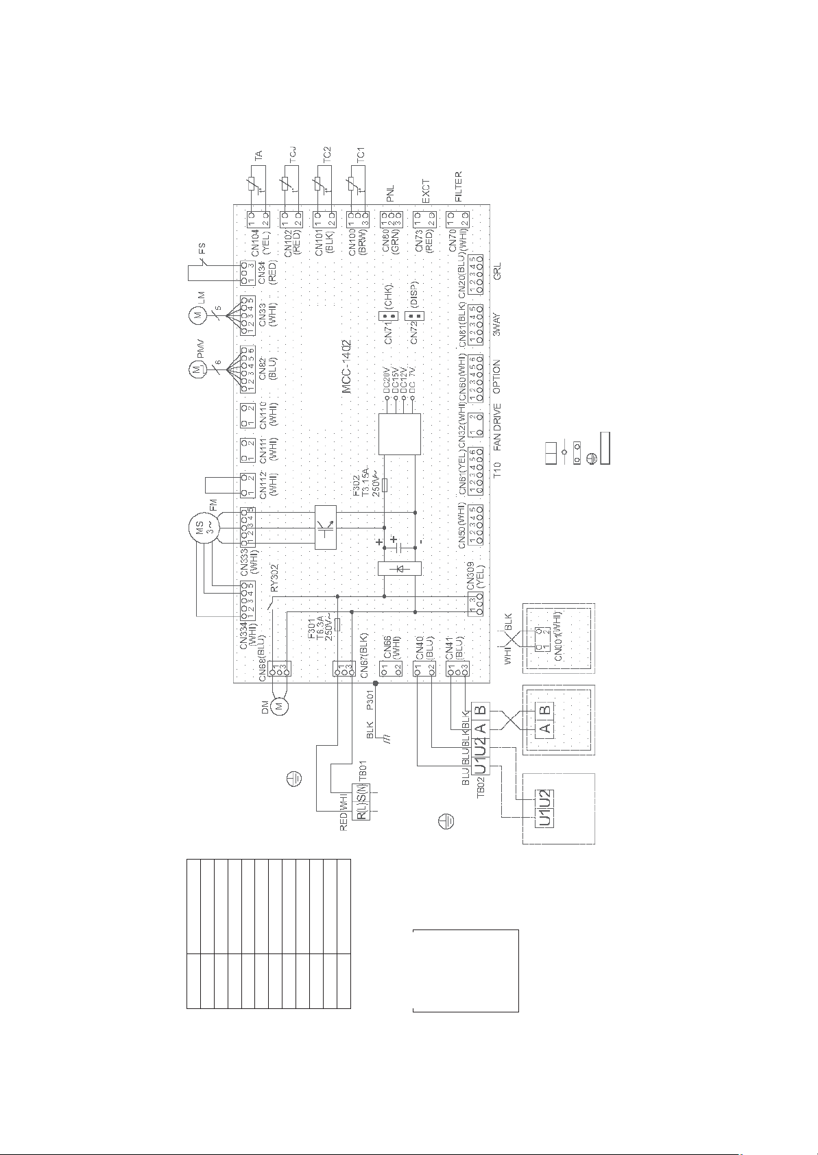
1-1. Compact 4-way cassette type
Models: MMU-AP0056MH-E(TR), AP0054MH-E(TR), AP0074MH-E(TR), AP0094MH-E(TR),
AP0124MH-E(TR),AP0154MH-E(TR), AP0184MH-E(TR)
Remote
Wireless
Controller
Adapter for
Controller
Wired Remote
Outdoor unit
(High ceiling
reshuffling)
Indoor unit
Earth screw
for Indoor Unit
Control P.C. Board
Power supply
Power
1~50Hz 220-240V
1~60Hz 220V
supply
indicates the connection terminal.
circuit
indicates the connector on the control P.C. board.
Long dashed short dashed line indicate the accessories.
1.Broken line indicate the wiring at site.
2. indicates the terminal block.
3. indicates the protection ground.
4. indicates the control P.C. board.
COLOR
IDENTIFICATION
RED : RED
BLU : BLUE
GRY : GRAY
PNK : PINK
BLK : BLACK
FS Float Switch
BRW : BROWN
ORN : ORANGE
GRN : GREEN
TA Indoor temp sensor
PMV Pulse Motor Valve
LM1,2 Louver Motor
RY302 Drain Control Relay
TB01,02 Terminal Block
TC1,2,TCJ Temp sensor
WHI : WHITE
YEL : YELLOW
FM Fan Motor
DM Drain Pump Motor
CN** Connector
Symbol Parts Name
F301,302 Fuse
Earth screw
Flow selector unit
– 15 –
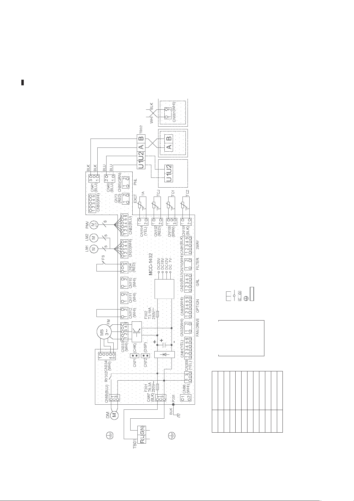
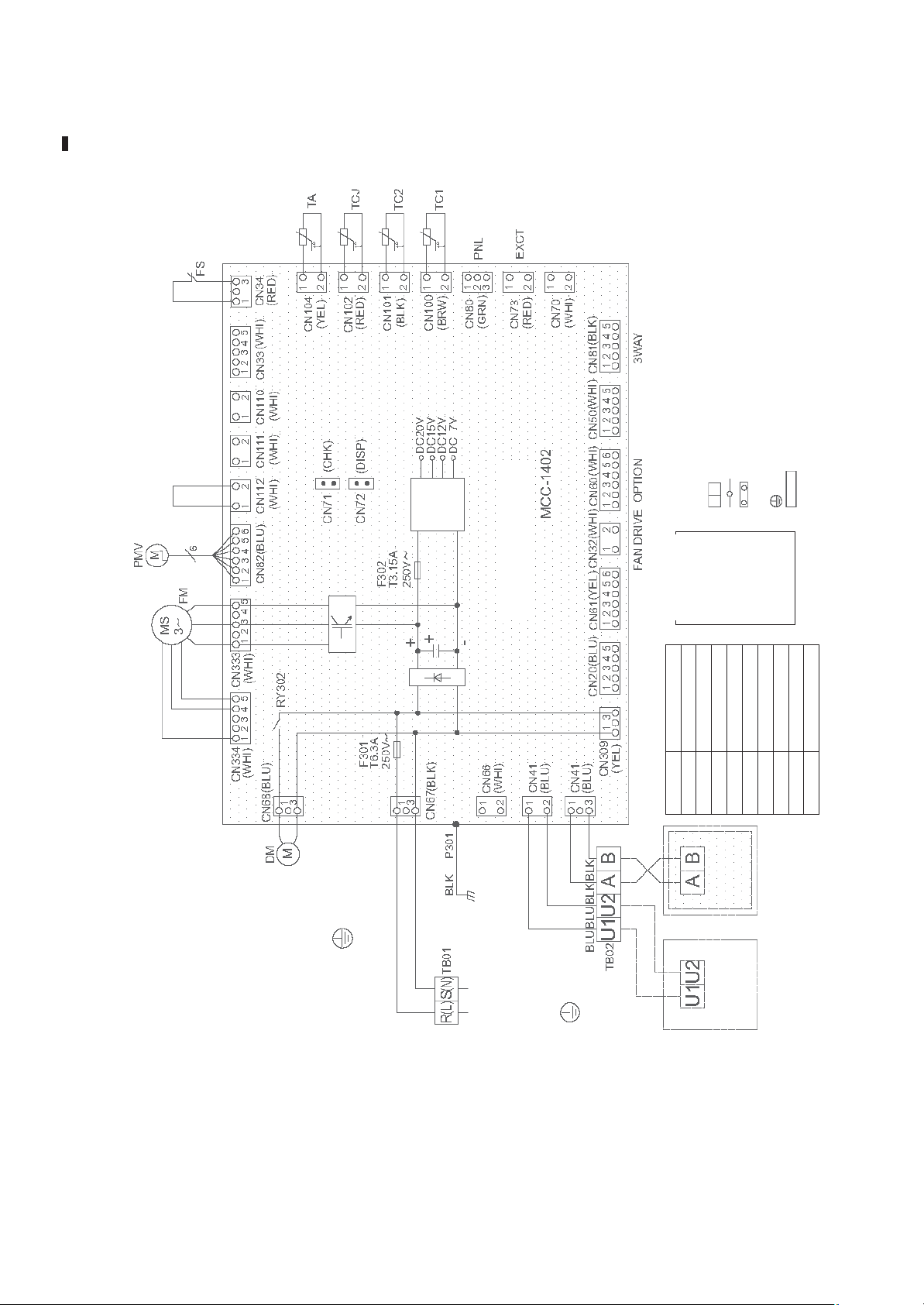
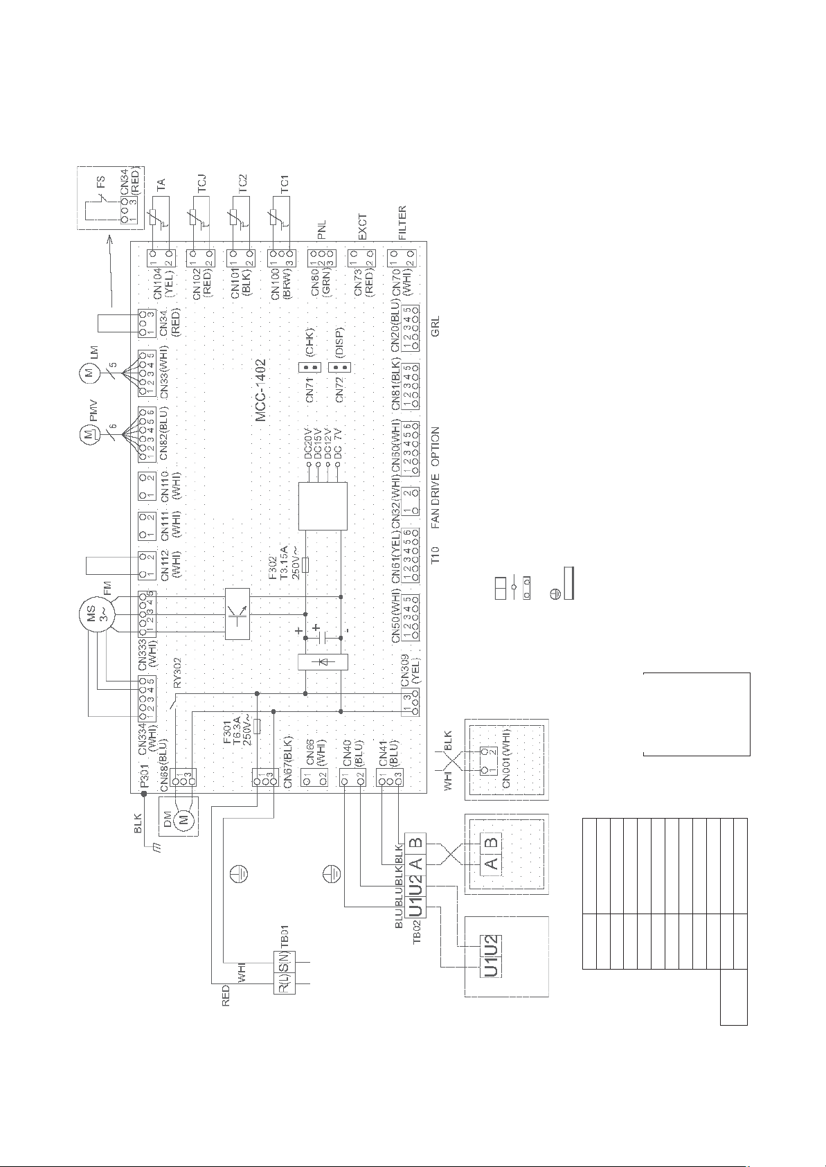
1-2. 1-way cassette type (compact type YH)
Models: MMU-AP0074YH-E(TR), AP0094YH-E(TR), AP0124YH-E(TR)
for Indoor Unit
Control P.C. Board
circuit
Power
supply
Sub P.C. Board
1.Broken line indicate the wiring at site.
Long dashed short dashed line indicate the accessories.
indicates the connection terminal.
2. indicates the terminal block.
indicates the connector on the control P.C. board.
3. indicates the protection ground.
4. indicates the control P.C. board.
Earth screw
Flow selector unit
COLOR
IDENTIFICATION
RED : RED
WHI : WHITE
YEL : YELLOW
BLU : BLUE
– 16 –
GRY : GRAY
PNK : PINK
BLK : BLACK
Power supply
ORN : ORANGE
1~50Hz 220-240V
1~60Hz 220V
GRN : GREEN
BRW : BROWN
Indoor unit
Earth screw
Line Filter
Symbol Parts Name
Remote Controller
Outdoor unit
Fan Motor Control Relay
FS Float Switch
LM Louver Motor
FM Fan Motor
DM Drain Pump Motor
CN** Connector
F301,302 Fuse
PMV Pulse Motor Valve
TA Indoor temp sensor
RY001 Louver Control Relay
RY002 Drain Control Relay
RY005,006,007
TR Transformer
TC,TCJ Temp sensor
TB01,02 Terminal Block
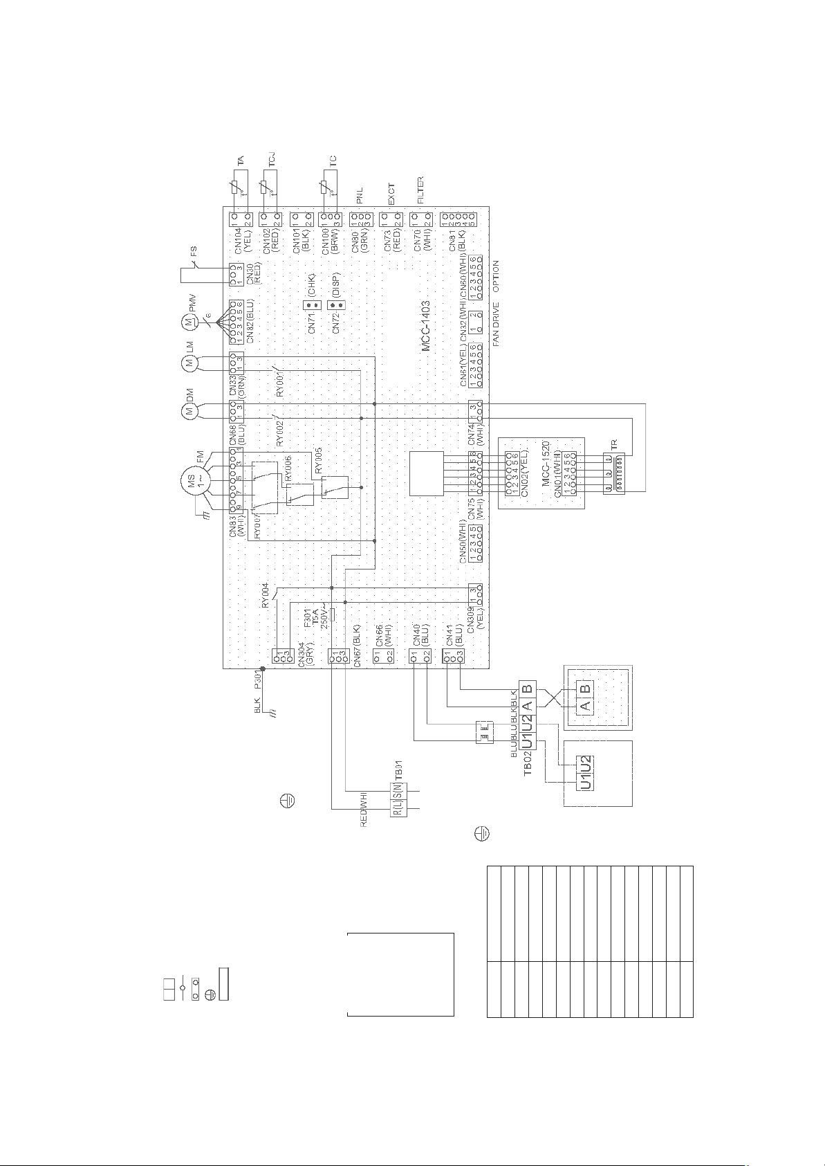
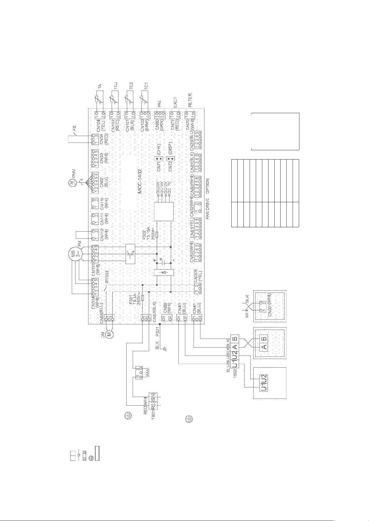
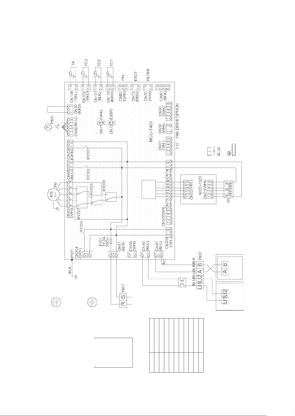
1-3. 1-way cassette type (SH)
Models: MMU-AP0154SH-E(TR), AP0184SH-E(TR), AP0244SH-E(TR)
for Indoor Unit
Control P.C. Board
circuit
Power
supply
(High ceiling
reshuffling)
Long dashed short dashed line indicate the accessories.
1.Broken line indicate the wiring at site.
indicates the connection terminal.
2. indicates the terminal block.
indicates the connector on the control P.C. board.
4. indicates the control P.C. board.
3. indicates the protection ground.
CN** Connector
Symbol Parts Name
Flow selector unit
FS Float Switch
FM Fan Motor
DM Drain Pump Motor
F301,302 Fuse
Earth screw
LM Louver Motor
PMV Pulse Motor Valve
RY302 Drain Control Relay
TA Indoor temp sensor
TB01,02 Terminal Block
Controller
Adapter for
Wireless Remote
Controller
Wired Remote
Power supply
Indoor unit
1~50Hz 220-240V
1~60Hz 220V
Earth screw
COLOR
TC1,2,TCJ Temp sensor
IDENTIFICATION
RED : RED
YEL : YELLOW
BLU : BLUE
BLK : BLACK
GRY : GRAY
WHI : WHITE
PNK : PINK
ORN : ORANGE
BRW : BROWN
GRN : GREEN
Outdoor unit
– 17 –
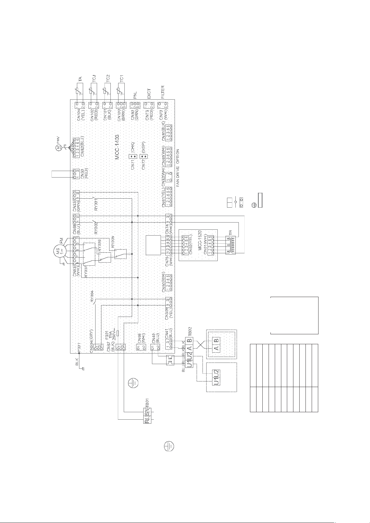
1-4. Concealed duct standard type
Models: MMD-AP0074BH-E(TR), AP0094BH-E(TR), AP0124BH-E(TR), AP0154BH-E(TR),
AP0184BH-E(TR), AP0244BH-E(TR), AP0274BH-E(TR), AP0304BH-E(TR),
AP0364BH-E(TR), AP0484BH-E(TR), AP0564BH-E(TR)
COLOR
IDENTIFICATION
(High ceiling
reshuffling)
for Indoor Unit
Control P.C. Board
circuit
Power
supply
WHI : WHITE
RED : RED
YEL : YELLOW
FS Float Switch
FM Fan Motor
DM Drain Pump Motor
CN** Connector
Symbol Parts Name
F301,302 Fuse
ORN : ORANGE
BLU : BLUE
BLK : BLACK
GRY : GRAY
PNK : PINK
TA Indoor temp sensor
PMV Pulse Motor Valve
RY302 Drain Control Relay
BRW : BROWN
GRN : GREEN
TB01,02 Terminal Block
TC1,2,TCJ Temp sensor
Long dashed short dashed line indicate the accessories.
1.Broken line indicate the wiring at site.
2. indicates the terminal block.
Earth screw
Flow selector unit
indicates the connector on the control P.C. board.
indicates the connection terminal.
4. indicates the control P.C. board.
3. indicates the protection ground.
Reactor
Power supply
1~50Hz 220-240V
1~60Hz 220V
Indoor unit
Earth screw
Outdoor unit
Controller
Adapter for
Wireless Remote
Controller
Wired Remote
– 18 –
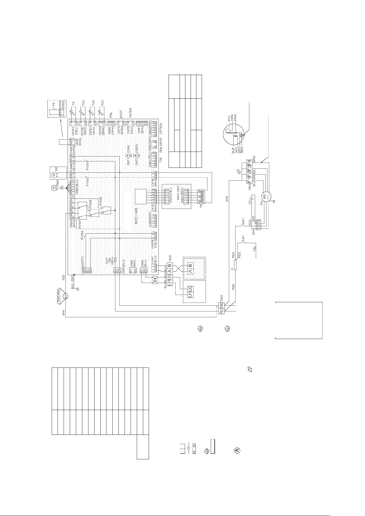
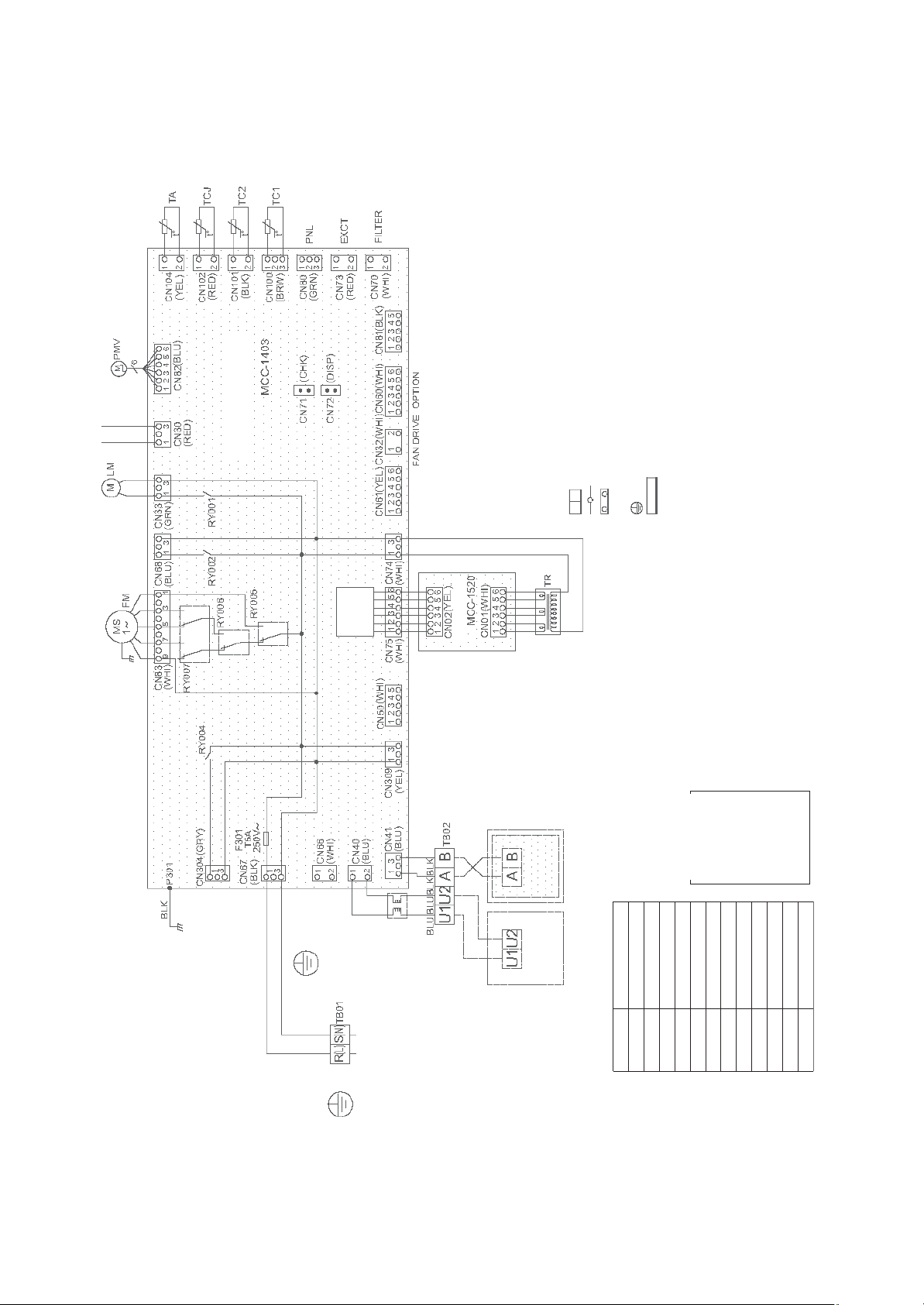
1-5. Concealed duct high static pressure type
Models: MMD-AP0184H-E(TR), AP0244H-E(TR), AP0274H-E(TR), AP0364H-E(TR),
AP0484H-E(TR)
Static
pressure tap
Motor over heating
protection switch
When drain
pump is installed
circuit
Power
supply
Fan motor wiring(MMD-)
Terminal
Sub P.C. Board
AP0484 AP0184~AP0364
No.
F1 BLU(50/60Hz) Low tap
F2 ORN(50/60Hz) Middle tap
F4 BRW(50Hz) — High tap
F3 BLK(60Hz) BLK(50/60Hz) High tap
Brown color wire.
Wired for MMD-AP0484H-E only
Fan motor inside wiring diagram (exp.)
(Refer tha static pressure specifications for each tap.)
for Indoor Unit
Control P.C. Board
Remote
Controller
unit
Line Filter
Outdoor
Fan motor Control Relay
Symbol Parts Name
43F1,F2
FFuse
FM Fan Motor
CN** Connector
F301 Fuse
PMV Pulse Motor Valve
RC Running Capacitor
RY002 Drain Control Relay
Fan Motor Control Relay
RY005,006,007
TA Indoor temp sensor
TB01,02,03 Terminal Block
FS Float Switch
TR Transformer
DM Drain Pump Motor
TC1,2,TCJ Temp sensor
Sold
Separately
1.Broken line indicate the wiring at site.
Long dashed short dashed line indicate
the accessories.
– 19 –
2. indicates the terminal block.
indicates the connection terminal.
Power supply
1~60Hz 220V
1~50Hz 220-240V
Indoor unit
Earth screw
Earth screw
Flow selector unit
indicates the connector on the
the froat switch connector to CN30
connector.
control P.C. board.
4. indicates the control P.C. board.
3. indicates the protection ground.
5.When installing the drain pump connect
block when change to static pressure.
Exchange the lead wire of arrow ( )
6. position is connected to terminal
COLOR
IDENTIFICATION
RED : RED
position after check the terminal
number as figure and lead wire's color
of fan motor.
pressure, the static pressure of high tap
7.Be careful when modify the static
WHI : WHITE
BLU : BLUE
YEL : YELLOW
is different by 50Hz or 60Hz.
GRY : GRAY
ORN : ORANGE
PNK : PINK
GRN : GREEN
BRW : BROWN
BLK : BLACK
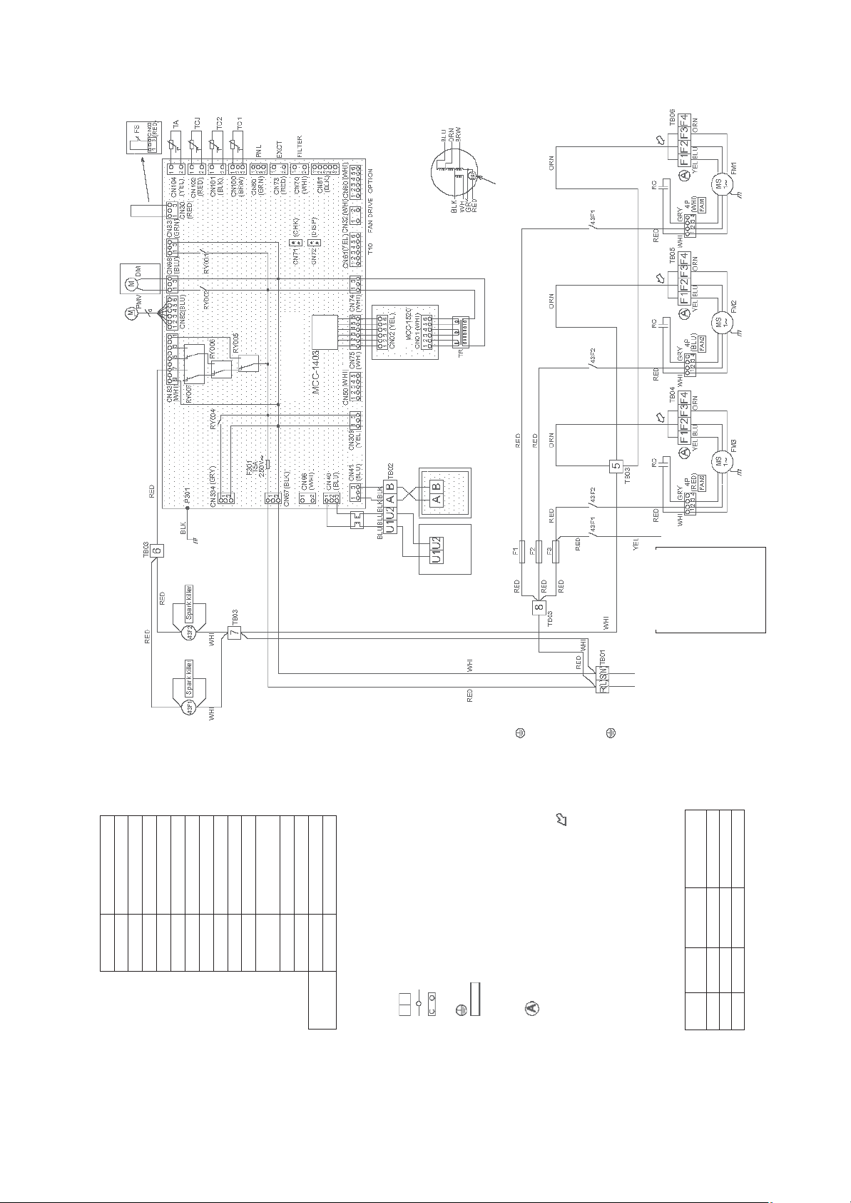
Models: MMD-AP0724H-E(TR), AP0964H-E(TR)
When drain
pump is installed
Fan motor inside wiring diagram
circuit
Power
supply
Sub P.C. Board
for Indoor Unit
Control P.C. Board
protection switch
Motor over heating
Remote
Controller
Fan motor Control Relay
Symbol Parts Name
43F1,F2
CN** Connector
F1,2,3 Fuse for Fan Motor
F301 Fuse
FM Fan Motor
PMV Pulse Motor Valve
unit
Line Filter
Terminal Block
Fan Motor Control Relay
RY002 Drain Control Relay
TA Indoor temp sensor
04,05,06
TB01,02,03,
RY005,006,007
RC Running Capacitor
TC1,2,TCJ Temp sensor
FS Float Switch
TR Transformer
DM Drain Pump Motor
Sold
Separately
Long dashed short dashed line indicate
the accessories.
1.Broken line indicate the wiring at site.
2. indicates the terminal block.
Outdoor
indicates the connection terminal.
indicates the connector on the
control P.C. board.
5.When installing the drain pump connect
3. indicates the protection ground.
4. indicates the control P.C. board.
Earth screw
Flow selector unit
the froat switch connector to CN30
connector.
6. position is connected to terminal
block when change to static pressure.
Exchange the lead wire of arrow ( )
position after check the terminal
Indoor unit
Earth screw
lead wire's color
of fan motor.
pressure, the static pressure of high tap
number as figure and
7.Be careful when modify the static
COLOR
IDENTIFICATION
RED : RED
WHI : WHITE
YEL : YELLOW
BLU : BLUE
GRY : GRAY
PNK : PINK
ORN : ORANGE
BRW : BROWN
BLK : BLACK
Power supply
1~60Hz 220V
1~50Hz 220-240V
Note
Pa (mmAq)
Static pressure
wiring
Fan motor
F1 YEL 69(7)
F2 BLU 137(14) Setting from factory
is different by 50Hz or 60Hz.
Terminal
No.
F3 ORN 196(20)
GRN : GREEN
– 20 –
1-6. Slim duct type
Models: MMD-AP0056SPH-E(TR), AP0054SPH-E(TR), AP0074SPH-E(TR),
AP0094SPH-E(TR), AP0124SPH-E(TR), AP0154SPH-E(TR), AP0184SPH-E(TR)
(High ceiling
reshuffling)
circuit
Power
supply
1.Broken line indicate the wiring at site.
indicates the connection terminal.
Long dashed short dashed line indicate the
accessories.
2. indicates the terminal block.
indicates the connector on the control P.C.
board.
4. indicates the control P.C. board.
3. indicates the protection ground.
Earth screw
Flow selector unit
Power supply
1~50Hz 220-240V
Control P.C. Board for
1~60Hz 220V
Indoor Unit
Indoor unit
Earth screw
COLOR
IDENTIFICATION
Symbol Parts Name
RED : RED
YEL : YELLOW
WHI : WHITE
DM Drain Pump Motor
CN** Connector
GRY : GRAY
BLK : BLACK
PNK : PINK
BLU : BLUE
FS Float Switch
FM Fan Motor
F301,302 Fuse
Outdoor unit
GRN : GREEN
BRW : BROWN
ORN : ORANGE
Terminal Block
TA Indoor temp sensor
RY302 Drain Control Relay
TB01,02
Controller
Wired Remote
Temp sensor
TC1,2,TCJ
– 21 –
1-7. Ceiling type
Models: MMC-AP0154H-E(TR), AP0184H-E(TR), AP0244H-E(TR), AP0274H-E(TR),
AP0364H-E(TR), AP0484H-E(TR)
When drain
pump is installed
Indoor Unit
Control P.C. Board for
(High ceiling
reshuffling)
Earth screw
Flow selector unit
Power
Indoor unit
Earth screw
supply
circuit
indicates the connection terminal.
indicates the connector on the control P.C.
accessories.
Long dashed short dashed line indicate the
1.Broken line indicate the wiring at site.
board.
2. indicates the terminal block.
3. indicates the protection ground.
Adapter for Wireless
Remote Controller
switch connector to CN34 connector.
5.When installing the drain pump connect the froat
4. indicates the control P.C. board.
COLOR
Remote Controller
IDENTIFICATION
WHI : WHITE
YEL : YELLOW
BLU : BLUE
BLK : BLACK
GRY : GRAY
Terminal Block
RED : RED
ORN : ORANGE
PNK : PINK
BRW : BROWN
GRN : GREEN
Power supply
1~60Hz 220V
1~50Hz 220-240V
– 22 –
Outdoor unit
CN** Connector
Symbol Parts Name
F301,302 Fuse
LM Louver Motor
FM Fan Motor
TA Indoor temp sensor
PMV Pulse Motor Valve
RY302 Drain Control Relay
TB01,02
TC1,2,TCJ Temp sensor
FS Float Switch
DM Drain Pump Motor
Sold
Separately
1-8. Floor standing cabinet type
Models: MML-AP0074H-E(TR), AP0094H-E(TR), AP0124H-E(TR), AP0154H-E(TR),
AP0184H-E(TR), AP0244H-E(TR)
Indoor Unit
Control P.C. Board for
circuit
Power
supply
1.Broken line indicate the wiring at site.
Sub P.C. Board
Long dashed short dashed line indicate the
accessories.
2. indicates the terminal block.
indicates the connection terminal.
indicates the connector on the control P.C.
board.
3. indicates the protection ground.
4. indicates the control P.C. board.
Remote Controller
Earth screw
Flow selector unit
Indoor unit
Earth screw
COLOR
IDENTIFICATION
RED : RED
WHI : WHITE
YEL : YELLOW
BLU : BLUE
BLK : BLACK
GRY : GRAY
PNK : PINK
ORN : ORANGE
BRW : BROWN
Power supply
GRN : GREEN
1~60Hz 220V
1~50Hz 220-240V
– 23 –
Symbol Parts Name
CN** Connector
F301 Fuse
Line Filter
Fan Motor Control Relay
TA Indoor temp sensor
TB01,02 Terminal Block
TC1,2,TCJ Temp sensor
TR Transformer
RC Running Capacitor
FM Fan Motor
PMV Pulse Motor Valve
RY005,006,007
Outdoor unit
1-9. Floor standing concealed type
Models: MML-AP0074BH-E(TR), AP0094BH-E(TR), AP0124BH-E(TR), AP0154BH-E(TR),
AP0184BH-E(TR), AP0244BH-E(TR)
Indoor Unit
Control P.C. Board for
indicates the connection terminal.
indicates the connector on the control P.C.
Flow selector unit
accessories.
Long dashed short dashed line indicate the
1.Broken line indicate the wiring at site.
circuit
Power
supply
Sub P.C. Board
Line Filter
Earth screw
Outdoor unit
2. indicates the terminal block.
Remote Controller
board.
3. indicates the protection ground.
4. indicates the control P.C. board.
CN** Connector
Symbol Parts Name
COLOR
IDENTIFICATION
BLU : BLUE
WHI : WHITE
RED : RED
YEL : YELLOW
FM Fan Motor
RC Running Capacitor
PMV Pulse Motor Valve
F301 Fuse
BLK : BLACK
GRY : GRAY
Fan Motor Control Relay
TA Indoor temp sensor
RY005,006,007
PNK : PINK
ORN : ORANGE
BRW : BROWN
GRN : GREEN
TR Transformer
TC1,2,TCJ Temp sensor
TB01,02,03 Terminal Block
Power supply
1~60Hz 220V
1~50Hz 220-240V
Indoor unit
Earth screw
– 24 –
1-10.Floor standing type
Models: MMF-AP0154H-E(TR), AP0184H-E(TR), AP0244H-E(TR), AP0274H-E(TR),
AP0364H-E(TR), AP0484H-E(TR), AP0564H-E(TR)
Indoor Unit
Control P.C. Board for
indicates the connection terminal.
indicates the connector on the control P.C.
Long dashed short dashed line indicate the
accessories.
1.Broken line indicate the wiring at site.
circuit
Power
supply
Sub P.C. Board
Remote Controller
2. indicates the terminal block.
board.
3. indicates the protection ground.
4. indicates the control P.C. board.
COLOR
IDENTIFICATION
RED : RED
WHI : WHITE
YEL : YELLOW
PNK : PINK
BLU : BLUE
BLK : BLACK
GRY : GRAY
ORN : ORANGE
BRW : BROWN
GRN : GREEN
unit Earth
Flow selector
Indoor unit
Earth screw
screw
Power supply
1~50Hz 220-240V
1~60Hz 220V
Line Filter
Outdoor unit
Fan Motor Control Relay
TA Indoor temp sensor
TB01,02,03 Terminal Block
TR Transformer
TC1,2,TCJ Temp sensor
CN** Connector
Symbol Parts Name
LM Louver Motor
FM Fan Motor
F301 Fuse
PMV Pulse Motor Valve
RC Running Capacitor
RY001 Louver Control Relay
RY005,006,007
– 25 –
2
Parts Rating
2-1. Indoor unit
Compact 4-way cassette type
Model MMU-AP 0184MH0154MH0124MH0094MH0074MH0054MH0056MH
1-way cassette type
sluP
R1-06-032-FWSrotom naF
N3Z42PMellirg latnoziroh rof rotoM
3-FT21DM-MDErotom esluP
EDM-B40YGTF-3EDM-B25YGTF-3evlav rotom esluP
t lyniV mm 551 :htgnel eriw daeLrosnes AT
ebu
ebut lyniV mm 0041 :htgnel eriw dael ezis 4Ørosnes 1CT
( ebut lyniV mm 0051 :htgnel eriw dael ezis 6Ørosnes 2CT
)kcalB
is 6Ørosnes JCT
301-8120-SFhctiws taolF
9041-PDArotom pmup niarD
1-N4-22-002-FArotom naF
Fµ 1 ,V 004 CArotom naf rof roticapac gninnuR
1-FT03250-DJProtom pmup niarD
8020-SFhctiws taolF
206-
31-TTremrofsnart draob .C.P lortnoC
3-FT21DM-MDErotom esluP
FTGY52B-MDEevlav rotom e
mm 818 :htgnel eriw daeLrosnes AT
)deR( ebut lyniV mm 0041 :htgnel eriw dael ez
HY4210HY4900HY4700PA-UMMledoM
)eulB( ebut lyniV mm 0021 :htgnel eriw dael ezis 4Ørosnes 1CT
R( ebut lyniV mm 0021 :htgnel eriw dael ezis 6Ørosnes JCT
)de
HS4420HS4810HS4510PA-UMMledoM
1-06-082-FWSrotom naF
1AG42PMellirg latnoziroh rof rotom gnivirD
3-FT21DM-MDErotom esluP
lav rotom esluP
l eriw daeLrosnes AT ength: 155 mm Vinyl tube
ezis 6Ørosnes JCT
3-FTGY04B-MDEev
)eulB( ebut lyniV mm 0011 :htgnel eriw dael ezis 4Ørosnes 1CT
lB( ebut lyniV mm 0011 :htgnel eriw dael ezis 6Ørosnes 2CT
)kca
)deR( ebut lyniV mm 0011 :htgnel eriw dael
301-8120-SFhctiws taolF
9041-PDArotom pmup niarD
– 26 –
Concealed duct standard type
Model MMD-AP 0074BH 0094BH 0124BH 0154BH 0184BH
2-021-082-FCIrotom naF
9041-PDArotom pmup niarD
201-8120-SFhctiws taolF
3-FT21DM-MDErotom esluP
DEFTGY52B-MDEevlav rotom esluP
mm 816 :htgnel eriw daeLrosnes AT
dael ezis 4Ørosnes 1CT
mm 0021 :htgnel eriw dael ezis 6Ørosnes JCT
Model MMD-AP 0244BH 0274BH 0304BH 0364BH 0484BH 0564BH
9041-PDArotom pmup niarD
201-8120-SFhctiws taolF
sluP
3-FT21DM-MDErotom e
mm 816 :htgnel eriw daeLrosnes AT
21 :htgnel eriw dael ezis 4Ørosnes 1CT
)eulB( ebut lyniV mm 0021 :htgnel eriw
)kcalB( ebut lyniV mm 0021 :htgnel eriw dael ezis 6Ørosnes 2CT
)deR( ebut lyniV
2-021-082-FCI1-021-082-FCIrotom naF
1-FTGY06B-MDEFTGY04B-MDEevlav rotom esluP
)eulB( ebut lyniV mm 00
)kcalB( ebut lyniV mm 0021 :htgnel eriw dael ezis 6Ørosnes 2CT
)
deR( ebut lyniV mm 0021 :htgnel eriw dael ezis 6Ørosnes JCT
FTGY04B-M
Concealed duct high static pressure type
Model MMD-AP 0184H 0244H 0274H 0364H 0484H
Running condenser for fan motor AC 500 V, 4 µF AC 400 V, 8 µF AC 450 V, 6 µF AC 400 V, 8 µF
9041-PDArotom pmup niarD
SFhctiws taolF
eLrosnes AT
tgnel eriw dael ezis 6Ørosnes 2CT
20-SFhctiws taolF
AT
w dael ezis 6Ørosnes 2CT
6-201-8120-
3-FT21DM-MDErotom esluP
1-FTGY06B-MDEFTGY04B-MDEevlav rotom esluP
mm 0021 :htgnel eriw da
)eulB( ebut lyniV mm 0021 :htgnel eriw dael ezis 4Ørosnes 1CT
)kcalB( ebut lyniV mm 0021 :h
)deR( ebut lyniV mm 0021 :htgnel eriw dael ezis 6Ørosnes JCT
H4690H4270PA-DMMledoM
A4-073-002-FTSrotom naF
Fµ 21 ,V 054 CArotom naf rof resnednoc gninnuR
9041-PDArotom pmup niarD
6-201-81
3-FT21DM-MDErotom esluP
1-FTGYOAB-MDEevlav rotom esluP
mm 818 :htgnel eriw daeLrosnes
)eulB( ebut lyniV mm 0002 :htgnel eriw dael ezis 4Ørosnes 1CT
)kcalB( ebut lyniV mm 0002 :htgnel eri
)deR( ebut lyniV mm 0002 :htgnel eriw dael ezis 6Ørosnes JCT
B4-062-002-FTSC4-062-002-FTSA4-061-002-FTSB4-061-002-FTSrotom naF
– 27 –
Slim duct type
Model MMD-AP 0184SPH0154SPH0124SPH0094SPH0074SPH0054SPH0056SPH
1-06-082-FWSrotom naF
3-FT21DM-MDErotom esluP
EDM-B40YGTFEDM-B25YGTFevlav rotom esluP
9041-PDArotom pmup niarD
iws taolF
tgnel eriw dael ezis 4Ørosnes 1CT h: 1200 mm Vinyl tube (Blue)
snes JCT
201-8120-SFhct
ebut lyniV mm 8551 :htgnel eriw daeLrosnes AT
lyniV mm 0021 :htgnel eriw dael ezis 6Ørosnes 2CT
)kcalB( ebut
)deR( ebut lyniV mm 0021 :htgnel eriw dael ezis 6Øro
Ceiling type
Model MMC-AP 0154H 0184H 0244H 0274H 0364H 0484H
1AG42PMellirg latnoziroh rof rotom gnivirD
otom esluP
l eriw daeLrosnes AT ength: 155 mm Vinyl tube
gnel eriw dael ezis 4Ørosnes 1CT
3-FT21DM-MDEr
)eulB( ebut lyniV mm 0021 :ht
)kcalB( ebut lyniV mm 0021 :htgnel eriw dael ezis 6Ørosnes 2CT
but lyniV mm 0021 :htgnel eriw dael ezis 6Ørosnes JCT
)deR( e
2-021-082-FWS2-06-082-FWS1-06-082-FWSrotom naF
1-FTGY06B-MDEFTGY04B-MDEevlav rotom esluP
Floor standing cabinet type
Model MML-AP 0074H 0094H 0124H 0154H 0184H 0244H
Running condenser for fan motor AC450 V, 1.2 µF AC400 V, 1.8 µF AC450 V, 2 µF
31TTremrofsnarT
3-FT21DM-MDErotom esluP
-MDEevlav rotom esluP
iw dael ezis 4Ørosnes 1CT
iV mm 0021 :htgnel eriw dael ezis 6Ørosnes JCT
FTGY04B-MDEFTGY52B
ebut lyniV mm 818 :htgnel eriw daeLrosnes AT
)eulB( ebut lyniV mm 0021 :htgnel er
)kcalB( ebut lyniV mm 0021 :htgnel eriw dael ezis 6Ørosnes 2CT
)deR( ebut lyn
Floor standing concealed type
Model MML-AP 0074BH 0094BH 0124BH 0154BH 0184BH 0244BH
K4-07-002-FAG4-91-002-FArotom naF
nnuR
31-TTremrofsnarT
3-FT21DM-MDErotom esluP
FTGY04B-MDEFTGY52B-MDEevlav rotom esluP
T ength: 818 mm Vinyl tube
l eriw daeLrosnes A
)eulB( ebut lyniV mm 0002 :htgnel eriw dael ezis 4Ørosnes 1CT
w dael ezis 6Ørosnes 2CT
)kcalB( ebut lyniV mm 0002 :htgnel eri
)deR( ebut lyniV mm 0002 :htgnel eriw dael ezis 6Ørosnes JCT
K4-07-002FAF4-54-002-FAF4-91-002-FArotom naF
Fµ 2 ,V 054CAFµ 1 ,V 054CAFµ 5.1 ,V 054CArotom naf rof resnednoc gni
– 28 –

Floor standing type
Model MMF-AP 0154H 0184H 0244H 0274H 0364H 0484H 0564H
Running condenser for fan motor AC500 V, 3 µF AC500 V, 3.5 µF AC500 V, 4 µF
31-TTremrofsnarT
3-FT21DM-MDErotom esluP
06B-MDEFTGY04B-MDEevlav rotom esluP
9-3-8TMrevuol lacitrev rof rotom gnivirD
eriw daeLrosnes AT
0002 :htgnel eriw dael ezis 6Ørosnes 2CT
ebut lyniV mm 0021 :htgnel
)eulB( ebut lyniV mm 0021 :htgnel eriw dael ezis 4Ørosnes 1CT
)kcalB( ebut lyniV mm
)deR( ebut lyniV mm 0021 :htgnel eriw dael ezis 6Ørosnes JCT
1-H061-002-FA1-M011-002-FAT36-002-FAR73-002-FArotom naF
1-FTGY
– 29 –
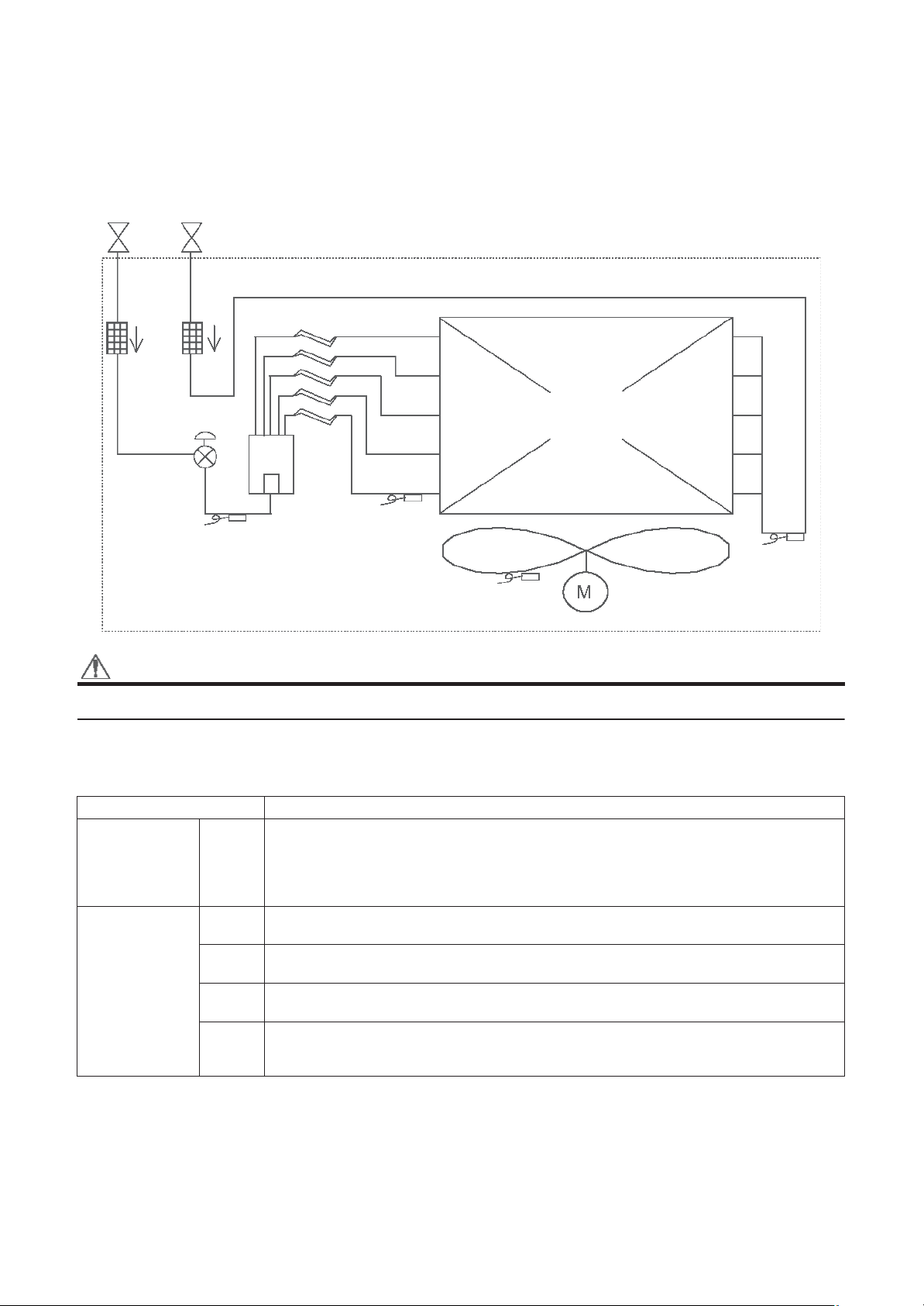
3
Refrigerant Cycle Diagram
Indoor unit
Liquid
side
Strainer
Pulse Motor
Valve (PMV)
Gas side
Sensor
(TC2)
Capillary tube
Sensor
(TCJ)
Heat exchanger at
indoor side
Fan
Sensor
(TA)
Fan motor
Sensor
(TC1)
CAUTION
MMU-AP0074YH, AP0094YH, AP0124YH type air conditioners have no TC2 sensor.
Explanation of functional parts in indoor unit
Pulse Motor Valve
Temp. Sensor
PMV
1.TA
2.TC1
3.TC2
4.TCJ
(Connector CN082 (6P): Blue)
1) Controls super heat in cooling operation
2) Controls under cool in heating operation
3) Recovers refrigerant oil in cooling operation
4) Recovers refrigerant oil in heating operation
(Connector CN104 (2P): Yellow)
1) Detects indoor suction temperature
(Connector CN100 (3P): Brown)
1) Controls PMV super heat in cooling operation
(Connector CN101 (2P): Black)
1) Controls PMV under cool in heating operation
(Connector CN102 (2P): Red)
1) Controls PMV super heat in cooling operation
2) [MMU-AP0074YH to AP0124YH only] Controls PMV under cool in heating operation
eniltuo lanoitcnuFeman trap lanoitcnuF
– 30 –
 Loading...