

Toshiba MMD-AP0186HP-E, MMD-AP0486HP-E, MMD-AP0566HP-E, MMD-AP0246HP-E, MMD-AP0276HP-E Installation Manual
...
AIR CONDITIONER (MULTI TYPE)
Installation Manual
English
For commercial use
Indoor Unit
Model name:
Concealed Duct High Static Pressure Type
MMD-AP0186HP-E
MMD-AP0246HP-E
MMD-AP0276HP-E
MMD-AP0366HP-E
MMD-AP0486HP-E
MMD-AP0566HP-E
1117065599 (01)_EN.indd 11117065599 (01)_EN.indd 1 01/07/15 3:42 PM01/07/15 3:42 PM
–1–
Original instruction
Contents
1 Precautions for safety . . . . . . . . . . . . . . . . . . . . . . . . . . . . . . . . . . . . . . . . . . . . . . . . . . 3
2 Accessory parts . . . . . . . . . . . . . . . . . . . . . . . . . . . . . . . . . . . . . . . . . . . . . . . . . . . . . . . 4
3 Selection of installation place. . . . . . . . . . . . . . . . . . . . . . . . . . . . . . . . . . . . . . . . . . . . 5
4 Installation . . . . . . . . . . . . . . . . . . . . . . . . . . . . . . . . . . . . . . . . . . . . . . . . . . . . . . . . . . .6
5 Drain piping . . . . . . . . . . . . . . . . . . . . . . . . . . . . . . . . . . . . . . . . . . . . . . . . . . . . . . . . . .8
6 Duct design. . . . . . . . . . . . . . . . . . . . . . . . . . . . . . . . . . . . . . . . . . . . . . . . . . . . . . . . . . 11
7 Refrigerant piping . . . . . . . . . . . . . . . . . . . . . . . . . . . . . . . . . . . . . . . . . . . . . . . . . . . . 12
8 Electrical connection . . . . . . . . . . . . . . . . . . . . . . . . . . . . . . . . . . . . . . . . . . . . . . . . . . 13
9 Applicable controls . . . . . . . . . . . . . . . . . . . . . . . . . . . . . . . . . . . . . . . . . . . . . . . . . . . 15
10 Test run . . . . . . . . . . . . . . . . . . . . . . . . . . . . . . . . . . . . . . . . . . . . . . . . . . . . . . . . . . . . . 17
11 Maintenance . . . . . . . . . . . . . . . . . . . . . . . . . . . . . . . . . . . . . . . . . . . . . . . . . . . . . . . . . 18
12 Troubleshooting . . . . . . . . . . . . . . . . . . . . . . . . . . . . . . . . . . . . . . . . . . . . . . . . . . . . . . 19
13 Specifications . . . . . . . . . . . . . . . . . . . . . . . . . . . . . . . . . . . . . . . . . . . . . . . . . . . . . . . . 24
Please read this Installation Manual carefully before installing the Air Conditioner.
• This Manual describes the installation method of the indoor unit.
• For installation of the outdoor unit, follow the Installation Manual attached to the outdoor unit.
ADOPTION OF NEW REFRIGERANT
This Air Conditioner uses R410A an environmentally friendly refrigerant.
Thank you for purchasing this Toshiba air conditioner.
Please read carefully through these instructions that contain important information which complies with the
“Machinery” Directive (Directive 2006/42/EC), and ensure that you understand them.
After completing the installation work, hand over this Installation Manual as well as the Owner’s Manual provided
to the user, and ask the user to keep them in a safe place for future reference.
Generic Denomination: Air Conditioner
Definition of Qualified Installer or Qualified Service Person
The air conditioner must be installed, maintained, repaired and removed by a qualified installer or qualified service
person. When any of these jobs is to be done, ask a qualified installer or qualified service person to do them for you.
A qualified installer or qualified service person is an agent who has the qualifications and knowledge described in
the following table.
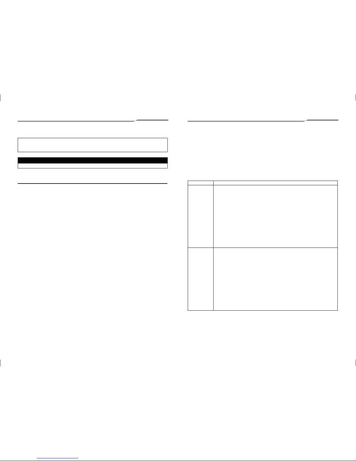
Agent Qualifications and knowledge which the agent must have
Qualified installer
• The qualified installer is a person who installs, maintains, relocates and removes the air conditioners
made by Toshiba Carrier Corporation. He or she has been trained to install, maintain, relocate and
remove the air conditioners made by Toshiba Carrier Corporation or, alternatively, he or she has been
instructed in such operations by an individual or individuals who have been trained and is thus
thoroughly acquainted with the knowledge related to these operations.
• The qualified installer who is allowed to do the electrical work involved in installation, relocation and
removal has the qualifications pertaining to this electrical work as stipulated by the local laws and
regulations, and he or she is a person who has been trained in matters relating to electrical work on
the air conditioners made by Toshiba Carrier Corporation or, alternatively, he or she has been
instructed in such matters by an individual or individuals who have been trained and is thus thoroughly
acquainted with the knowledge related to this work.
• The qualified installer who is allowed to do the refrigerant handling and piping work involved in
installation, relocation and removal has the qualifications pertaining to this refrigerant handling and
piping work as stipulated by the local laws and regulations, and he or she is a person who has been
trained in matters relating to refrigerant handling and piping work on the air conditioners made by
Toshiba Carrier Corporation or, alternatively, he or she has been instructed in such matters by an
individual or individuals who have been trained and is thus thoroughly acquainted with the knowledge
related to this work.
• The qualified installer who is allowed to work at heights has been trained in matters relating to working
at heights with the air conditioners made by Toshiba Carrier Corporation or, alternatively, he or she
has been instructed in such matters by an individual or individuals who have been trained and is thus
thoroughly acquainted with the knowledge related to this work.
Qualified service
person
• The qualified service person is a person who installs, repairs, maintains, relocates and removes the
air conditioners made by Toshiba Carrier Corporation. He or she has been trained to install, repair,
maintain, relocate and remove the air conditioners made by Toshiba Carrier Corporation or,
alternatively, he or she has been instructed in such operations by an individual or individuals who have
been trained and is thus thoroughly acquainted with the knowledge related to these operations.
• The qualified service person who is allowed to do the electrical work involved in installation, repair,
relocation and removal has the qualifications pertaining to this electrical work as stipulated by the local
laws and regulations, and he or she is a person who has been trained in matters relating to electrical
work on the air conditioners made by Toshiba Carrier Corporation or, alternatively, he or she has been
instructed in such matters by an individual or individuals who have been trained and is thus thoroughly
acquainted with the knowledge related to this work.
• The qualified service person who is allowed to do the refrigerant handling and piping work involved in
installation, repair, relocation and removal has the qualifications pertaining to this refrigerant handling
and piping work as stipulated by the local laws and regulations, and he or she is a person who has
been trained in matters relating to refrigerant handling and piping work on the air conditioners made
by Toshiba Carrier Corporation or, alternatively, he or she has been instructed in such matters by an
individual or individuals who have been trained and is thus thoroughly acquainted with the knowledge
related to this work.
• The qualified service person who is allowed to work at heights has been trained in matters relating to
working at heights with the air conditioners made by Toshiba Carrier Corporation or, alternatively, he
or she has been instructed in such matters by an individual or individuals who have been trained and
is thus thoroughly acquainted with the knowledge related to this work.
1-EN 2-EN
1117065599 (01)_EN.indd 21117065599 (01)_EN.indd 2 01/07/15 3:42 PM01/07/15 3:42 PM
–2–
Definition of Protective Gear
When the air conditioner is to be transported, installed, maintained, repaired or removed, wear protective gloves
and ‘safety’ work clothing.
In addition to such normal protective gear, wear the protective gear described below when undertaking the special
work detailed in the following table.
Failure to wear the proper protective gear is dangerous because you will be more susceptible to injury, burns,
electric shocks and other injuries.
nrow raeg evitcetorPnekatrednu kroW
All types of work
Protective gloves
‘Safety’ working clothing
Electrical-related
work
Gloves to provide protection for elec
tricians
Insulating shoes
Clothing to provide protection from electric shock
Work done at heights
(50 cm or more)
Helmets for use in industry
Transportation of
heavy objects
Shoes with additional protective toe cap
Repair of outdoor unit Gloves to provide protection for electricians
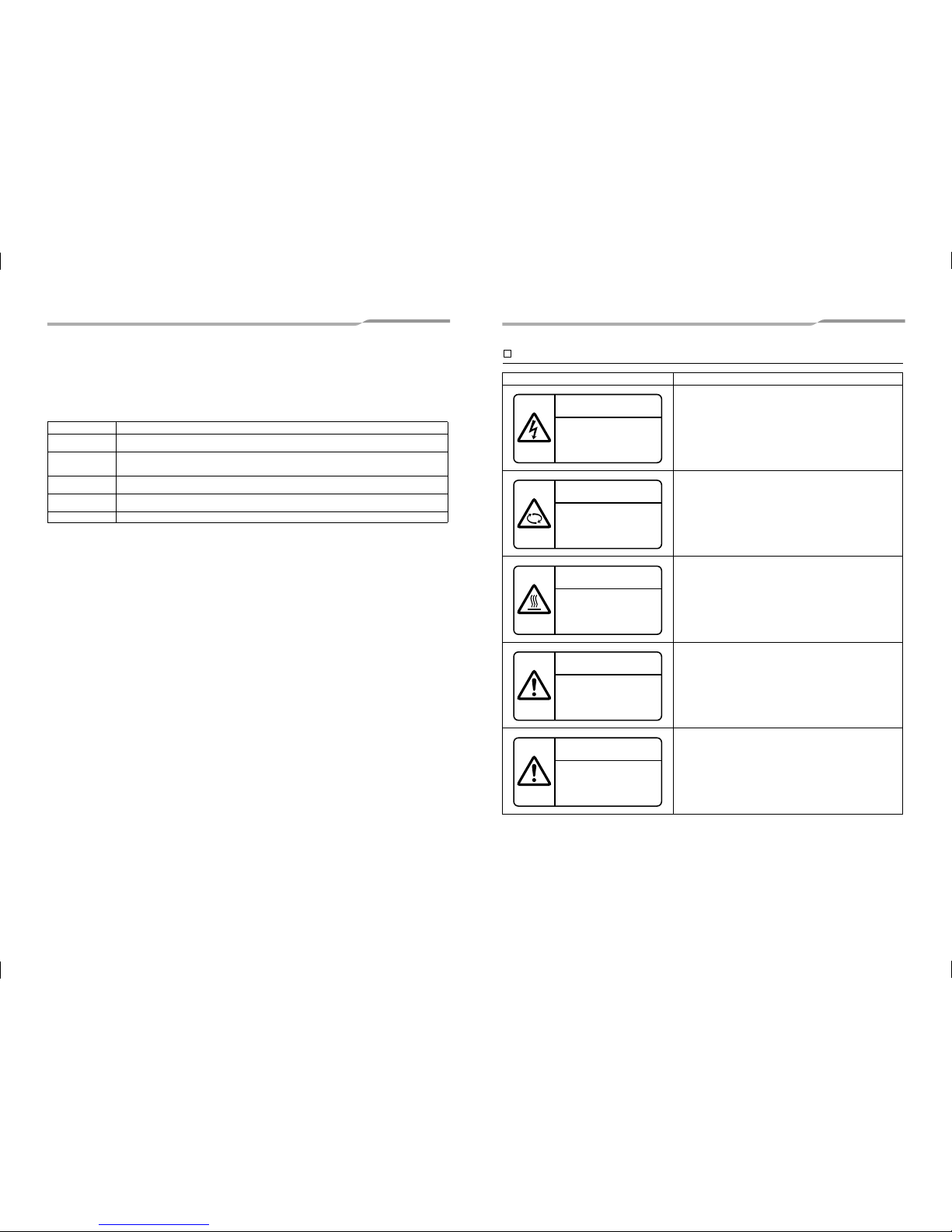
Warning indications on the air conditioner unit
noitpircseDnoitacidni gninraW
WARNING
ELECTRICAL SHOCK HAZARD
Disconnect all remote electric power supplies before servicing.
WARNING
Moving parts.
Do not operate unit with grille removed.
Stop the unit before the servicing.
CAUTION
High temperature parts.
You might get burned when removing this panel.
CAUTION
Do not touch the aluminium fins of the unit.
Doing so may result in injury.
CAUTION
BURST HAZARD
Open the service valves before the operation, otherwise there might be
the burst.
WARNING
ELECTRICAL SHOCK HAZARD
Disconnect all remote
electric power supplies
before servicing.
WARNING
Moving parts.
Do not operate unit with grille
removed.
Stop the unit before the servicing.
CAUTION
High temperature parts.
You might get burned
when removing this panel.
CAUTION
Do not touch the aluminum
fins of the unit.
Doing so may result in injury.
CAUTION
BURST HAZARD
Open the service valves before
the operation, otherwise there
might be the burst.
3-EN 4-EN
1117065599 (01)_EN.indd 31117065599 (01)_EN.indd 3 01/07/15 3:42 PM01/07/15 3:42 PM
–3–
1
Precautions for safety
The manufacturer shall not assume any liability for the damage caused by not observing the description of this
manual.
WARNING
General
Before starting to install the air conditioner, read through the Installation Manual carefully, and follow its instructions
to install the air conditioner.
Only a qualified installer or service person is allowed to do installation work. Inappropriate installation may result in
water leakage, electric shock or fire.
Do not use any refrigerant different from the one specified for complement or replacement. Otherwise, abn ormally
high pressure may be generated in the refr
igeration cycle, which may result in a failure or explosion of the product o r
an injury to your body.
Before opening the electrical control box cover of the indoor unit or service panel of the outdoor unit, set the circuit
breaker to the OFF position. Failure to set the circuit brea ker to the OFF position may result in electric shocks through
contact with the interior parts. Only a qualified installer(*1) or qualified ser vice person(*1) is allowed to remove the
electrical control box cover of the
indoor unit or service panel of the outdoor unit and do the work required.
Before carrying out the installation, maintenance, repair or removal work, set the circuit breaker to t he OFF position.
Otherwise, electric shocks may result.
Place a “Work in progress” sign near the circuit breaker while the installation, maintenance, repair or removal work
is being carried out. There is a danger of electric shocks if the circu it breaker is set to ON by mistake.
Only a qualified installe
r(*1) or qualified service person(*1) is allowed to undertake work at heights using a stand of
50 cm or more or to remove the intake grille of the indoor un it to undertake work.
Wear protective gloves and safety work clothing during installation, servicing and removal.
Do not touch the aluminium fin of the unit. You may injure yourself if you do so. If the fin must be touched for some
reason, first put on protective gloves and safety work clothing, a nd then proceed.
Before opening the in
spection opening, set the circuit breaker to the OFF position. Failu re to set the circuit breaker
to the OFF position may result in injury through contact with the rota tion parts. Only a qualified installer (*1) or
qualified service person(*1) is allowed to remove the inspection opening and do the work required.
When work is performed at heights, use a ladder which complies with the ISO 14122 standard, and follow the
procedure in the ladder’s instructions. Also wear a helmet for use in ind
ustry as protective gear to undertake the work.
Before cleaning the filter (sold separately) or other parts of the outdoor unit, set the circuit breaker to OFF without
fail, and place a “Work in progress” sign near the circuit breaker bef ore proceeding with the work.
Before working at heights, put a sign in place so that no-one will approach the work location, before proceeding with
the work. Parts and other objects may fall from above, possibly injuring a person belo w. While carrying out the work,
wea
r a helmet for protection from falling objects.
The refrigerant used by this air conditioner is the R410A.
The air conditioner must be transported in stable condition. If any part of the product is broken, contact the de aler.
When the air conditioner must be transported by hand, carry it by four or more people.
Do not move or repair any unit by yourself. There is high voltage inside the unit. You may get electric shock when
removing the cover and main unit.
Selection of installation location
When the air conditioner is installed in a small room, provide appropriate measures to ensure that the concentration
of refrigerant leakage occur in the room does not exceed t he critical level.
Do not install in a location where flammable gas leaks are possible. If the gas leak and accumulate around the unit,
it may ignite and cause a fire.
To transport the air conditioner, wear shoes with additional protective toe caps.
To transport the air conditioner, do not take hold of the bands around the packing cart
on. You may injure yourself if
the bands should break.
Install the indoor unit at least 2.5 m above the floor level since otherwise the users may injure t hemselves or receive
electric shocks if they poke their fingers or other objects into the indoor unit while the air conditioner is running.
Do not place any combustion appliance in a place where it is directly exposed to the wind of air co nditioner, otherwise
it may cause imperfect combustion.
Installation
Suction duct length must be longer than 850 mm.
When the indoor unit is to be suspended, the designated hanging bolts (M10 or W3/8) and nuts (M10 or W3/8) must
be used.
Install the air conditioner securely in a location where the base can sustain the weight adequately. If the stren gth is
not enough, the unit may fall down resulting in injury.
Follow the instructions in the Installation Manual to install the air conditioner. Failure to follow these instructions may
cause the product to fall down or topple over o
r give rise to noise, vibration, water leakage or other trou ble.
Carry out the specified installation work to guard against the possibility of high winds and earthquake. If the air
conditioner is not installed appropriately, a unit may topple over or fall down, causin g an accident.
If refrigerant gas has leaked during the installation work, ventilate the room immediately. If the leaked refrigerant gas
comes in contact with fire, noxious gas may generate.
Use forklift to carry in the air conditioner units a
nd use winch or hoist at installation of them.
Helmet must be worn to protect your head from falling objects.
Especially, when you work under an inspection opening, helmet must be worn to protect your head from falling
objects from the opening.
Refrigerant piping
Install the refrigerant pipe securely during the installation work before operating the air conditioner. If the compressor
is operated with the valve open and without refrigerant pipe, the compressor sucks air and the refrigeration cycles is
over pressurized, which may cause a injury.
Tighten the flare nut with a torque wrench in the specified manner. Excessive tighten of the flare nut may cause a
crack in the flare nut after a long period, which may result in refr igerant leakage.
After the installation work, confirm that refrigerant gas does not leak. If refrigerant gas leaks into the room and flows
near a fire source, such as a cooking range, noxious gas may b e generated.
When the air conditioner has been installed o
r relocated, follow the instructions in the Installation Manual and purge
the air completely so that no gases other than the refrig erant will be mixed in the refrigerating cycle. Failure to purge
the air completely may cause the air conditioner to malfunction .
Nitrogen gas must be used for the airtight test.
The charge hose must be connected in such a way that it is not slack.
Electrical wiring
Only a qualified installer(*1) or qualified service person(*1) is allowed to carry out the electrical work of the air
conditioner. Under no circumstances must this work be d one by an unqualified individual since failure to carry out the
work properly may result in electric shocks and/or electrical leaks.
To connect the electrical wires, repair the electrical parts or undertake other electrical jobs, wear gloves to provide
protection for electricians, insulating shoes and clothing to provide protection from electric shocks. Failure to wear
this protective gear may result in electric shocks.
Use wiring that meets
the specifications in the Installation Manual and the stipulation s in the local regulations and
laws. Use of wiring which does not meet the specifications may give rise to ele ctric shocks, electrical leakage,
smoking and/or a fire.
Connect earth wire. (Grounding work)
Incomplete grounding causes an electric shock.
Do not connect earth wires to gas pipes, water pipes, and lightning conductor or telephone earth wires.
After completing the repair or relocation work, check that the earth wires are connected properly.
Install
a circuit breaker that meets the specifications in the installation manual and the stipulations in the local
regulations and laws.
Install the circuit breaker where it can be easily accessed by the agent.
When installing the circuit breaker outdoors, install one which is designed to be used outdoors.
Under no circumstances the power wire must not be extended. Connection trouble in the places where the wire is
extended may give rise to smoking and/or a fire.
Electrical wiring work shall be condu
cted according to law and regulation in the community and installatio n manual.
Failure to do so may result in electrocution or short circuit.
5-EN 6-EN
1117065599 (01)_EN.indd 41117065599 (01)_EN.indd 4 01/07/15 3:42 PM01/07/15 3:42 PM
–4–
Test run
Before operating the air conditioner after having completed the work, check that the electrical control box cover of the
indoor unit and service panel of the outdoor unit are closed, and s et the circuit breaker to the ON position. You may
receive an electric shock if the power is turned on without first conducting th ese checks.
If there is any kind of trouble (such as an error display has appeared, smell of burning, abnormal sounds , the air
conditioner fails to cool or heat or water
is leaking) has occurred in the air conditioner, do not touch the air con ditioner
yourself but set the circuit breaker to the OFF position, and conta ct a qualified service person. Take steps to ensure
that the power will not be turned on (by marking “out of serv ice” near the circuit breaker, for instance) until qualified
service person arrives. Continuing to use the air conditioner in the trouble status may cause mechanical problems to
escalate or result in electric shocks or other trouble.
Aft
er the work has finished, use an insulation tester set (500 V Me gger) to check the resistance is 1 MΩ or more
between the charge section and the non-charge metal section (Earth section). If the resistance value is low, a disaster
such as a leak or electric shock is caused at user’s side.
Upon completion of the installation work, check for refrigerant leaks and check the insulation resistance an d water
drainage. Then conduct a test run to check that the air con ditioner is operating
properly.
Explanations given to user
Upon completion of the installation work, tell the user where the circuit breaker is located. If the user does not know
where the circuit breaker is, he or she will not be able to turn it off in the event that trouble has occurred in the air
conditioner.
After the installation work, follow the Owner’s Manual to explain to the customer how to use and maintain the unit.
Relocation
Only a qualified installer(*1) or qualified service person(*1) is allowed to relocate the air conditioner. It is dangerous
for the air conditioner to be relocated by an unqualified individ ual since a fire, electric shocks, injury, water leakage,
noise and/or vibration may result.
When carrying out the pump-down work shut down the compressor before disconnecting the refrigerant pipe.
Disconnecting the refrigerant pipe with the service valve left op en and the compressor still operating will cause air or
other gas to be sucked in, raising the pressure inside
the refrigeration cycle to an abnormally high level, and p ossibly
resulting in rupture, injury or other trouble.
CAUTION
New refrigerant air conditioner installation
This air conditioner adopts the new HFC refrigerant (R410A) which does not destroy ozone layer.
The characteristics of R410A refrigerant are; easy to absorb water, oxidizing membrane or oil, and its pre ssure is
approx. 1.6 times higher than that of refrigerant R22. Accompanied with the new refrigerant, refrigerating oil has also
been changed. Therefore, do not let water, dust, former re frigerant, or refrigerating oil enter the refrigerating cycle
during installation
work.
To prevent charging an incorrect refrigerant and refrigerating oil, the sizes of connecting sections of charging port of
the main unit and installation tools are changed from those fo r the conventional refrigerant.
Accordingly the exclusive tools are required for the new refrigerant (R410A).
For connecting pipes, use new and clean piping designed for R410A, and please care so that water or dust does not
enter.
To disconnect the appliance from main power supply.
This appliance must be connected to the main power supply by means of a switch with a contact separation of at
least 3 mm.
The installation fuse (all types can be used) must be used for the power supply line of this conditioner.
(*1) Refer to the “Definition of Qualified Installer or Qualified Service Person.”
2
Accessory parts
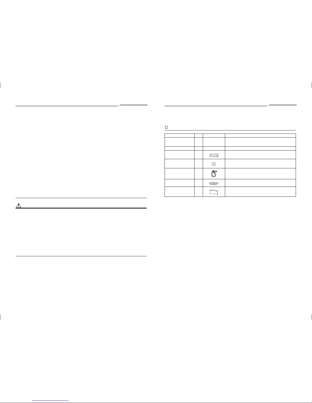
Accessory parts
egasUepahSyt’Qeman traP
Installation Manual 1 This manual
(Hand over to customers)
(For other languages that do not appear in this Installation Manual,
please refer to the enclosed CD-R.)
CD-ROM 1 — Installation Manual
usni taeh roF2epip gnitalusni taeH lation of pipe connecting section
tinu nwod-gnignah roF8rehsaW
epip niard
gnitcennoc roF1dnab esoH
epip niard fo retnec gnitsujda roF1esoh elbixelF
italusni taeh roF1rotalusni t
aeH on of drain connecting section
7-EN 8-EN
1117065599 (01)_EN.indd 51117065599 (01)_EN.indd 5 01/07/15 3:42 PM01/07/15 3:42 PM
–5–
3
Selection of installation place
Avoid installing in the following places
Select a location for the indoor unit where the cool or warm air will circulate evenly.
Avoid installation in the following kinds of locations.
Saline area (coastal area)
Locations with acidic or alkaline atmospheres (such as areas with hot springs, factories where chemicals or
pharmaceuticals are made and places where the exhaust air from combustion appliances will be sucked into the
unit).
Doing so may cause the heat exchanger (its aluminum fins and copper pipes) and other parts to become
corroded.
Locations with atmospheres with mist of cutting oil or other types of machine oil.
Doing so may cause the heat exchanger
to become corroded, mists caused by the blockage of the heat
exchanger to be generated, the plastic parts to be damaged, the heat insulators to peel off, and other such
problems to result.
Places where iron or other metal dust is present. If iron or other metal dust adheres to or collects on the interior
of the air conditioner, it may spontaneously combust and start a fire.
Locations where vapors from food oils are formed (such as kitchens where food oils are used).
Blocked filters may cause the air conditioner’s performance to deteriorate, condensation to form, the plastic parts
to be damaged,
and other such problems to result.
Locations near obstructions such as ventilation openings or lighting fixtures where the flow of the blown air will
be disrupted (a disruption of the air flow may cause the air conditioner’s performance to deteriorate or the unit to
shut down).
Locations where an in-house power generator is used for the power supply.
The power line frequency and voltage may fluctuate, and the air conditioner may not work properly as a result.
On truck cranes, ships or other moving conveyances.
The air conditioner must not be used for special applications (such as for storing food, plants, precision
instruments or art works).
(The quality of the items stored may be degraded.
)
Locations where high frequencies are generated (by inverter equipment, in-house power generators, medical
equipment or communication equipment).
(Malfunctioning or control trouble in the air conditioner or noise may adversely affect the equipment’s operation.)
Locations where there is anything under the unit installed that would be compromised by wetness.
(If the drain has become blocked or when the humidity is over 80 %, condensation from the indoor unit will drip,
possibly causing damage to anything underneath.)
In the case of the wireless type of system, rooms with the inverter type of fluorescent lighting or locations
exposed to direct sunlight.
(The signals from
the wireless remote controller may not be sensed.)
Locations where organic solvents are being used.
The air conditioner cannot be used for liquefied carbonic acid cooling or in chemical plants.
Location near doors or windows where the air conditioner may come into contact with high-temperature, high-
humidity outdoor air.
(Condensation may occur as a result.)
Locations where special sprays are used frequently.
Installation under high-humidity atmosphere
In some cases including the rainy season, especially inside of the ceiling may become high-humidity atmosphere
(dew-point temperature: 23 °C or higher).
1. Installation to inside of the ceiling with tiles on the roof
2. Installation to inside of the ceiling with slated roof
3. Installation to a place where inside of the ceiling is used for pathway to intake the fresh air
4. Installation to a kitchen
In the above cases, additionally attach the heat insulator to all positions of the air conditioner, which come to
contact with the high-humidity atmosphere.
In this case, arrange the side plate (Check port) so that it is easily
removed.
Apply also a sufficient heat insulation to the duct and connecting part of the duct.
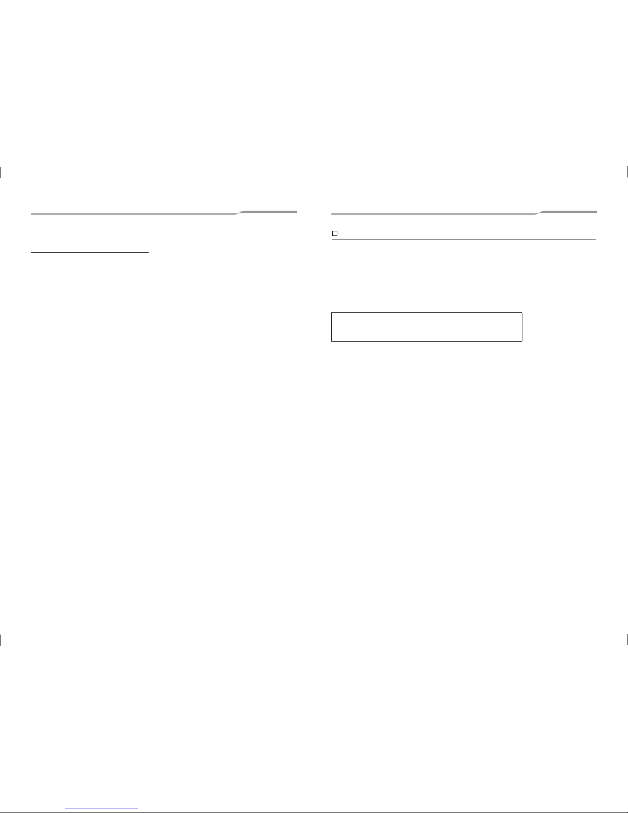
[Reference] Condensation test conditions
Indoor side:
27 °C dry bulb temperature
24 °C wet bulb temperature
Air volume: Low air volume, operation time 4 hours
9-EN 10-EN
1117065599 (01)_EN.indd 61117065599 (01)_EN.indd 6 01/07/15 3:42 PM01/07/15 3:42 PM
–6–
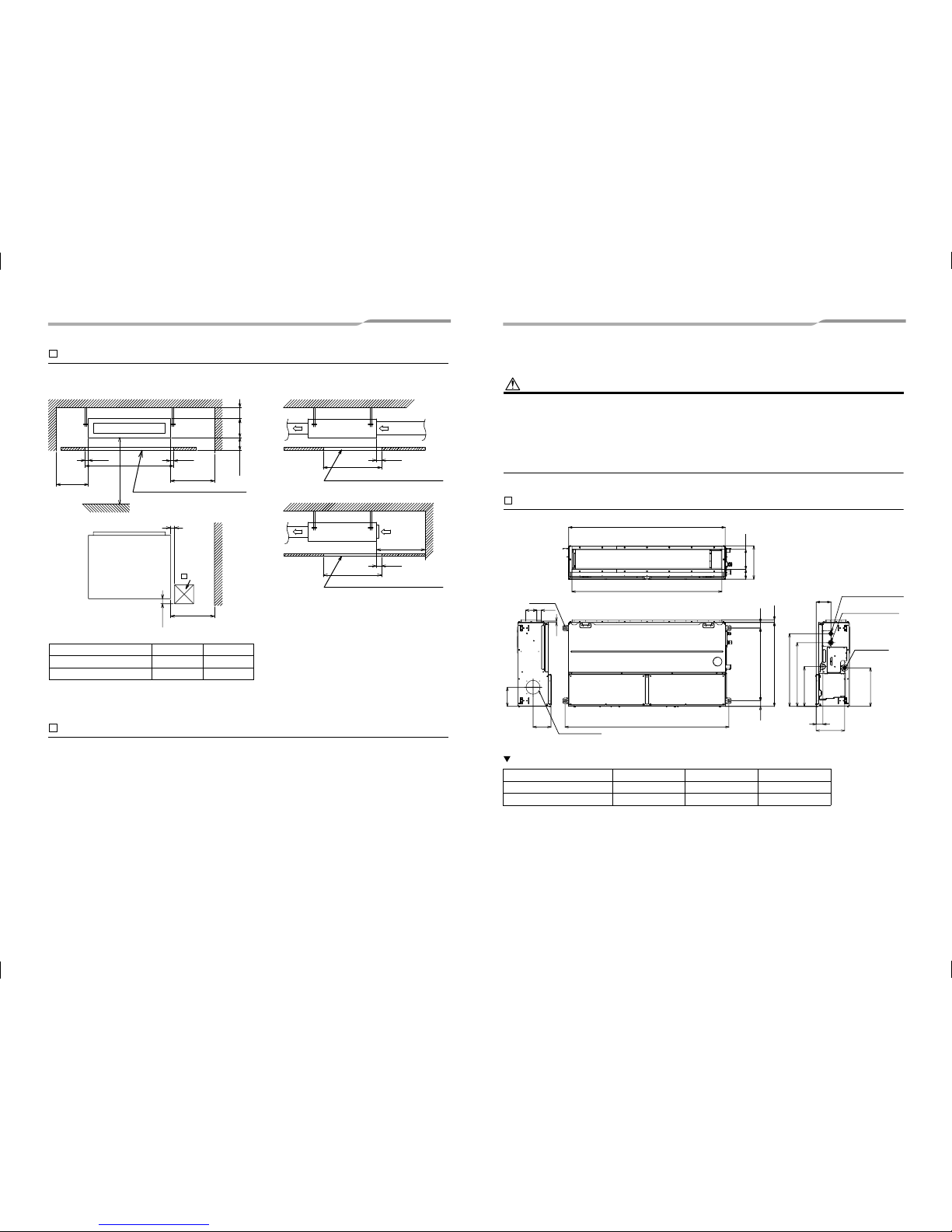
Installation space (Unit: mm)
Reserve sufficient space required for installation or service work.
Filter cleaning sign term setting
The lighting term setup of the filter sign (Notification of filter cleaning) of the remote controller can be changed
according to the condition of installation.
For setup method, refer to “Filter sign setting” in the Applicable controls of this Manual.
100 or
more
Air discharge
Ceiling
25
A
25
2500 or
more
B
or more
70 or
more
5 or
more
275
Inspection opening (Ceiling opening)
Floor surface
Air discharge
100 or more
450
Check port
120
Service space
(B for maintenance of air filter (Sold separately))
B
Air intake
570
25
Ceiling
Inspection opening (Ceiling opening)
Air intake
570
25
Ceiling
Inspection opening (Ceiling opening)
300 or more
AB
4
Installation
CAUTION
Strictly comply with the following rules to prevent damage of the indoor units and human injury.
Do not put a heavy article on the indoor unit or let a person get on it. (Even units are packaged)
Carry in the indoor unit as it is packaged if possible. If carrying in the indoor unit unpacked by necessity, use buffering
cloth or other material to not damage the unit.
To move the indoor unit, hold the hooking brackets (4 positions) only.
Do not apply force to the other parts (such as refrigeran
t pipe, drain pan, foamed parts, or resin parts).
Carry the package by four or more persons, and do not bundle it with plastic band at positions other than spec ified.
To install vibration isolation material to hanging bolts, confirm that it does not increase the unit vibration.
External dimensions (Unit: mm)
Dimension
ABC
11-EN 12-EN
AP0186~AP0276 1050 500
AP0366~AP0566 1450 700
650 5050
(4-Ø12×30)
Hole for hanging bolt
Hanging bolt mounting pitch
355
570
650
345
60
Drain pipe
connecting port
Ø125 Knockout hole
For Auxiliary fresh air flange
170
160
180
298
750
87
255
(Sold separately)
131
40
100
13
22
Refrigerant pipe
connecting port (Liquid side)
Refrigerant pipe
connecting port (Gas side)
Main unit dimension A
External dimension of flange C
Hanging bolt mounting pitch B
AP0186~AP0276 1000 1065 940
AP0366~AP0566 1400 1465 1340
1117065599 (01)_EN.indd 71117065599 (01)_EN.indd 7 01/07/15 3:42 PM01/07/15 3:42 PM
–7–
Installation of hanging bolt
Consider the piping / wiring after the unit is hung to
determine the location of the indoor unit installation
and orientation.
After the location of the indoor unit installation has
been determined, install hanging bolts.
For the dimensions of the hanging bolt pitches, refer
to the external view.
When a ceiling already exists, lay the drain pipe,
refrigerant pipe, control wires, and remote controller
wires to their connection locations before hanging
the indoor unit.
Procure hanging bolts washer and nuts for installing
the indoor unit (these are not supplied).
Installation of hanging bolt
Use M10 hanging bolts (4 pcs, locally procured).
Matching to the existing structure, set pitch according
to size in the unit external view as shown below.
Installation of indoor unit
Treatment of ceiling
The ceiling differs according to structure of building.
For details, consult your constructor or interior finish
contractor.
In the process after the ceiling board has been
removed, it is important to reinforce ceiling foundation
(frame) and to keep horizontal level of installed ceiling
correctly in order to prevent vibration of ceiling board.
Attach the nuts and the M10 flat washers to the
hanging bolt.
Put washers at up and down of the hanging bracket
of the indoor unit to hang down the indoor unit.
Check that four sides are horizontal with a level
gauge. (Horizontal degree: Within 5 mm)
REQUIREMENT
Hang the unit in a horizontal position.
When unit is hanged to slant, it may cause overflow of
drainage.
Install the unit within the dimension according to the
figure below.
Use level gauge to confirm whether the unit is hang
horizontally.
Hanging bolt M10 or W3/8 4 pieces
Nut M10 or W 3/8 12 pieces
Washer M10 8 pieces
New concrete slab
Install the bolts with insert brackets or anchor bolts.
Steel flame structure
Use existing angles or install new support angles.
Existing concrete slab
Use a hole-in anchors, hole-in plugs, or a hole-in bolts.
Rubber
Anchor bolt
(Blade type
bracket)
(Slide type
bracket)
(Pipe hanging
anchor bolt)
Hanging bolt
Hanging bolt
Support angle
Nut
(W3/8 or M10)
M10 flat washer
M10 flat washer
Hanging bolt
(W3/8 or M10)
Nut
(W3/8 or M10)
±5 mm
Set the air intake and air
discharge sides are within 5 mm
with each other.
Set the drain pipe connecting
port side within 28 mm lower
than opposite side.
Side view
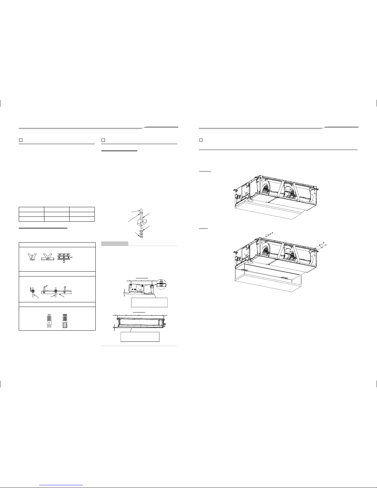
Removing the foamed polystyrene and three plates for
transportation
1
Remove three plates from air inlet side.
Remove the foamed polystyrene from bottom side after setting indoor unit at hanging bolt.
13-EN 14-EN
Front view
Before
After
2
23 to 28 mm
1117065599 (01)_EN.indd 81117065599 (01)_EN.indd 8 01/07/15 3:42 PM01/07/15 3:42 PM
–8–
5
Drain piping
CAUTION
Following the Installation Manual, perform the drain piping work so that water is properly drained. Apply a heat
insulation so as not to cause a dew condensation.
Inappropriate piping work may result in water l eakage in the room and wet furniture.
Provide the indoor drain piping with proper heat insulation.
Provide the area where the pipe connects to the indoor unit with proper heat insulation. Improper heat insulation
will cause condensation to form.
The drain pipe must be sloping downward (at an angle of 1/100 or more), and do not run the pipe up and down
(arched shape) or allow it to form traps. Doing so may cause abnormal sounds.
Restrict the length of the traversing drain pipe to 20 meters or less. For a long pipe, provide support brackets at
intervals of 1.5 to 2 meters to prevent flapping.
Install the collective piping as shown in the following figure.
Do not provide any air
vents. Otherwise, the drain water will spout, causing water to leak.
Do not allow any force to be applied to the connection area with the drain pipe.
Pipe material, size and insulator
The following materials for piping work and insulating process are locally procured.
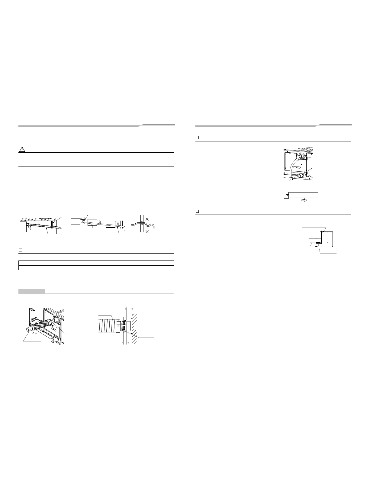
Connecting drain pipe
Insert flexible drain hose into upper drain pipe of main unit as far as it will go. Fix it with hose band.
REQUIREMENT
Mount the flexible drain hose using the hose band without using adhesive.
Pipe material Hard vinyl chloride pipe VP25 (Nominal outer diameter Ø32 mm)
Insulator Foamed polyethylene foam, thickness: 10 mm or more
1.5 m to 2 m
Support
bracket
Downward slope
1/100 or more
Arched shape
Trap
Downward slope
1/100 or more
(Collective
piping)
As long as possible
(Approx. 10 cm)
Heat
insulator
Incorrect
VP30
Flexible
drain hose
Hose band
Flexible
drain hose
Hose band
Indoor unit
10 to 12 mm
15 mm or less
10 mm
Gravitational drainage
Drain up
1
Reattach the drain cap.
* For gravitational drainage, remove the white connector
(CN504) on the upper left of the circuit board in the
electrical control box.
2
Insert flexible drain hose into lower drain pipe and
fix it with hose band.
3
Remove drain pump connector CN504.
When a down-gradient cannot be secured for the drain pipe, drain-up
piping is possible.
The height of the drain pipe must be 850 mm or less from the underside
of the indoor unit.
Take the drain pipe out of the drain pipe joint with the indoor unit in 300
mm or less, and bend up the pi
pe vertically.
Immediately after the pipe is bent up vertically, lay the pipe making a
down-gradient.
Move the drain cap from
the lower pipe to the
upper pipe.
Lower pipe
Upper pipe
Red
CN504
Black
850 or less
Drain up setup dimensions
Flexible drain hose
(supplied)
618 or less
For drain pipes that will be
connected after setup, make a
downward slope of 1/100 or more.
300 or less
15-EN 16-EN
1117065599 (01)_EN.indd 91117065599 (01)_EN.indd 9 01/07/15 3:42 PM01/07/15 3:42 PM
 Loading...