

Toshiba MMD-AP0181SPH, MMD-AP0071SH-C, MMD-AP0091SPH, MMD-AP0151SPH, MMD-AP0121SPH DATA BOOK
...Page 1

FILE NO. A05-006
SERVICE MANUAL
<Slim Duct Type>
MMD-AP0071SPH (-C, -K),
MMD-AP0091SPH (-C, -K),
MMD-AP0121SPH (-C, -K),
MMD-AP0151SPH (-C, -K),
MMD-AP0181SPH (-C, -K),
MMD-AP0071SH-C,
MMD-AP0091SH-C,
MMD-AP0121SH-C,
MMD-AP0151SH-C,
MMD-AP0181SH-C,
• This Service Manual describes contents of the new Slim Duct indoor unit.
For the outdoor unit, refer to the Manual with FILE NO. A03-009.
PRINTED IN JAPAN, Jul.,2005 ToMo
Page 2

CONTENTS
SAFETY CAUTION ............................................................................................ 3
1. CONSTRUCTION VIEWS (EXTERNAL VIEWS) ........................................ 8
2. WIRING DIAGRAM..................................................................................... 9
3. PARTS RATING........................................................................................ 10
4. FAN CHARACTERISTICS........................................................................ 50
5. REFRIGERANTING CYCLE DIAGRAM................................................... 52
6. CONTROL OUTLINE................................................................................ 53
7. APPLIED CONTROL................................................................................ 57
8. TROUBLESHOOTING .............................................................................. 62
9. CONFIGURATION OF CONTROL CIRCUIT .......................................... 113
10. DETACHMENTS ..................................................................................... 118
11. P.C. BOARD EXCHANGE PROCEDURES ............................................ 123
12. EXPLODED VIEWS AND PARTS LIST .................................................. 128
2
Page 3
SAFETY CAUTION
The important contents concerned to the safety are described on the product itself and on this Service Manual.
Please read this Service Manual after understanding the described items thoroughly in the following contents,
and keep them.
WARNING
Before troubleshooting or repair work, check the earth wire is connected to the earth
terminals of the main unit, otherwise an electric shock is caused when a leak occurs.
Check earth wires.
Prohibition of modification.
Use specified parts.
Do not bring a child
close to the equipment.
Insulating measures
No fire
If the earth wire is not correctly connected, contact an electric engineer for rework.
Do not modify the products.
Do not also disassemble or modify the parts. It may cause a fire, electric shock or injury.
For spare parts, use those specified (
If unspecified parts are used, a fire or electric shock may be caused.
∗: For details, refer to the parts list.
Before troubleshooting or repair work, do not bring a third party (a child, etc.) except
the repair engineers close to the equipment.
It causes an injury with tools or disassembled parts.
Please inform the users so that the third party (a child, etc.) does not approach the equipment.
Connect the cut-off lead cables with crimp contact, etc, put the closed end side
upward and then apply a water-cut method, otherwise a leak or production of fire is
caused at the users’ side.
When repairing the refrigerating cycle, take the following measures.
1) Be attentive to fire around the cycle. When using a gas stove, etc, be sure to put out fire
before work; otherwise the oil mixed with refrigerant gas may catch fire.
2) Do not use a welder in the closed room. When using it without ventilation, carbon
monoxide poisoning may be caused.
3) Do not bring inflammables close to the refrigerant cycle, otherwise fire of the welder may
catch the inflammables.
∗∗
∗).
∗∗
Refrigerant
Check the used refrigerant name and use tools and materials of the parts which
match with it.
For the products which use R410A refrigerant, the refrigerant name is indicated at a
position on the outdoor unit where is easy to see. To prevent miss-charging, the route of the
service por t is changed from one of the former R22.
For an air conditioner which uses R410A, never use other refrigerant than R410A.
For an air conditioner which uses other refrigerant (R22, etc.), never use R410A.
If different types of refrigerant are mixed, abnormal high pressure generates in the refrigerating cycle and an injury due to breakage may be caused.
Do not charge refrigerant additionally.
If charging refrigerant additionally when refrigerant gas leaks, the refrigerant composition in
the refrigerating cycle changes resulted in change of air conditioner characteristics or
refrigerant over the specified standard amount is charged and an abnormal high pressure is
applied to the inside of the refrigerating cycle resulted in cause of breakage or injury.
Therefore if the refrigerant gas leaks, recover the refrigerant in the air conditioner, execute
vacuuming, and then newly recharge the specified amount of liquid refrigerant. In this time,
never charge the refrigerant over the specified amount.
When recharging the refrigerant in the refrigerating cycle, do not mix the refrigerant
or air other than R410A into the specified refrigerant.
If air or others is mixed with the refrigerant, abnormal high pressure generates in the
refrigerating cycle resulted in cause of injury due to breakage.
After installation work, check the refrigerant gas does not leak.
If the refrigerant gas leaks in the room, poisonous gas generates when gas touches to fire
such as fan heater, stove or cocking stove though the refrigerant gas itself is innocuous.
Never recover the refrigerant into the outdoor unit.
When the equipment is moved or repaired, be sure to recover the refr igerant with recovering device. The refrigerant cannot be recovered in the outdoor unit; otherwise a serious
accident such as breakage or injury is caused.
3
Page 4
Assembly/Cabling
Insulator check
Ventilation
Be attentive to
electric shock
Compulsion
WARNING
After repair work, surely assemble the disassembled parts, and connect and lead the
removed cables as before. Perform the work so that the cabinet or panel does not
catch the inner cables.
If incorrect assembly or incorrect cable connection was done, a disaster such as a leak or
fire is caused at user’s side.
After the work has finished, be sure to use an insulation tester set (500V mugger) to
check the resistance is 2MW or more between the charge section and the non-charge
metal section (Earth position).
If the resistance value is low, a disaster such as a leak or electric shock is caused at user’s
side.
When the refrigerant gas leaks during work, execute ventilation.
If the refrigerant gas touches to a fire, poisonous gas generates. A case of leakage of the
refrigerant and the closed room full with gas is dangerous because a shortage of oxygen
occurs. Be sure to execute ventilation.
When checking the circuit inevitably under condition of the power-ON, use rubber
gloves and others not to touch to the charging section.
If touching to the charging section, an electric shock may be caused.
When the refrigerant gas leaks, find up the leaked position and repair it surely.
If the leaked position cannot be found up and the repair work is interrupted, pump-down
and tighten the service valve, otherwise the refrigerant gas may leak into the room.
The poisonous gas generates when gas touches to fire such as fan heater, stove or cocking
stove though the refrigerant gas itself is innocuous.
When installing equipment which includes a large amount of charged refrigerant such
as a multi air conditioner in a sub-room, it is necessar y that the density does not the
limit even if the refrigerant leaks.
If the refrigerant leaks and exceeds the limit density, an accident of shortage of oxygen is
caused.
For the installation/moving/reinstallation work, follow to the Installation Manual.
If an incorrect installation is done, a trouble of the refrigerating cycle, water leak, electric
shock or fire is caused.
Check after rerair
Check after reinstallation
Put on gloves
Cooling check
After repair work has finished, check there is no trouble.
If check is not executed, a fire, electric shock or injury may be caused. For a check, turn off
the power breaker.
After repair work (installation of front panel and cabinet) has finished, execute a test
run to check there is no generation of smoke or abnormal sound.
If check is not executed, a fire or an electric shock is caused. Before test run, install the
front panel and cabinet.
Check the following items after reinstallation.
1) The earth wire is correctly connected.
2) The power cord is not caught in the product.
3) There is no inclination or unsteadiness and the installation is stable.
If check is not executed, a fire, an electric shock or an injury is caused.
CAUTION
Be sure to put on gloves (
If not putting on gloves, an injury may be caused with the parts, etc.
(∗) Heavy gloves such as work gloves
When the power was turned on, start to work after the equipment has been
sufficiently cooled.
As temperature of the compressor pipes and others became high due to cooling/heating
operation, a burn may be caused.
∗∗
∗) during repair work.
∗∗
4
Page 5

• New Refrigerant (R410A)
This air conditioner adopts a new HFC type refrigerant (R410A) which does not deplete the ozone layer.
1. Safety Caution Concerned to New Refrigerant
The pressure of R410A is high 1.6 times of that of the former refrigerant (R22). Accompanied with change of
refrigerant, the refrigerating oil has been also changed. Therefore, be sure that water, dust, the former refrigerant or the former refrigerating oil is not mixed into the refrigerating cycle of the air conditioner with new refrigerant during installation work or service work. If an incorrect work or incorrect service is performed, there is a
possibility to cause a serious accident. Use the tools and materials exclusive to R410A to purpose a safe work.
2. Cautions on Installation/Service
(1) Do not mix the other refrigerant or refrigerating oil.
For the tools exclusive to R410A, shapes of all the joints including the service port differ from those of the
former refrigerant in order to prevent mixture of them.
(2) As the use pressure of the new refrigerant is high, use material thickness of the pipe and tools which are
specified for R410A.
(3) In the installation time, use clean pipe materials and work with great attention so that water and others do
not mix in because pipes are affected by impurities such as water, oxide scales, oil, etc. Use the clean
pipes.
Be sure to brazing with flowing nitrogen gas. (Never use gas other than nitrogen gas.)
(4) For the earth protection, use a vacuum pump f or air purge.
(5) R410A refrigerant is azeotropic mixture type refrigerant. Theref ore use liquid type to charge the refrigerant.
(If using gas for charging, composition of the refrigerant changes and then characteristics of the air condi-
tioner change.)
3. Pipe Materials
For the refrigerant pipes, copper pipe and joints are mainly used. It is necessary to select the most appropriate
pipes to conform to the standard. Use clean material in which impurities adhere inside of pipe or joint to a
minimum.
(1) Copper pipe
<Piping>
The pipe thickness, flare finishing size, flare nut and others differ according to a refrigerant type.
When using a long copper pipe for R410A, it is recommended to select “Copper or copper-base pipe without
seam” and one with bonded oil amount 40mg/10m or less. Also do not use crushed, deformed, discolored
(especially inside) pipes. (Impurities cause clogging of expansion valves and capillary tubes.)
<Flare nut>
Use the flare nuts which are attached to the air conditioner unit.
(2) Joint
The flare joint and socket joint are used for joints of the copper pipe.
The joints are rarely used for installation of the air conditioner. How ever clear impurities when using them.
5
Page 6
4. Tools
(1) Required Tools for R410A
Mixing of different types of oil may cause a trouble such as generation of sludge, clogging of capillary, etc.
Accordingly, the tools to be used are classified into the following three types.
1) Tools exclusive for R410A (Those which cannot be used for conventional refrigerant (R22))
2) Tools exclusive for R410A, but can be also used for conventional refrigerant (R22)
3) Tools commonly used for R410A and for conventional refrigerant (R22)
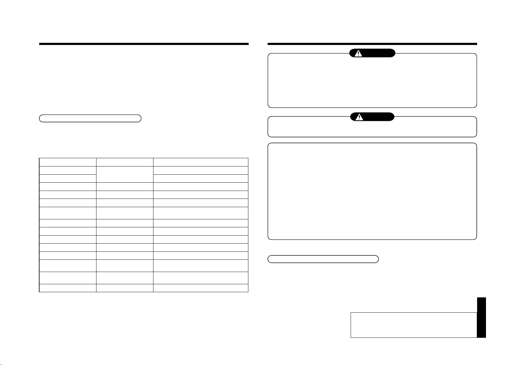
The table below shows the tools exclusive for R410A and their interchangeability.
Tools exclusive for R410A (The following tools for R410A are required.)
Tools whose specifications are changed for R410A and their interchangeability
Conventional air
conditioner installation
Whether new equipment
can be used with
conventional refrigerant
Yes
*(Note 1)
No
No
Yes
Yes
No
Yes
No
No.
Q
R
S
T
U
V
W
X
Y
Y
Used tool
Flare tool
Copper pipe gauge for
adjusting projection
margin
Torque wrench
Gauge manifold
Charge hose
Vacuum pump adapter
Electronic balance for
refrigerant charging
Refrigerant cylinder
Leakage detector
Charging cylinder
Usage
Pipe flaring
Flaring by conventional
flare tool
Connection of flare nut
Evacuating, refrigerant
charge, run check, etc.
Vacuum evacuating
Refrigerant charge
Refrigerant charge
Gas leakage check
Refrigerant charge
air conditioner installation
Existence of
new equipment
for R410A
Yes
Yes
Yes
Yes
Yes
Yes
Yes
Yes
(Note 2)
R410A
Whether conventional equipment can
be used
*(Note 1)
*(Note 1)
No
No
No
Yes
No
No
No
(Note 1) When flaring is carried out for R410A using the conventional flare tools, adjustment of projection
margin is necessary. For this adjustment, a copper pipe gauge , etc. are necessary.
(Note 2) Charging cylinder for R410A is being currently dev eloped.
General tools (Conventional tools can be used.)
In addition to the above exclusive tools, the following equipments which serve also for R22 are necessary
as the general tools.
(1) Vacuum pump
Use vacuum pump b y
attaching vacuum pump adapter.
(2) Torque wrench
(3) Pipe cutter
(4) Reamer
(7) Screwdriver (+, –)
(8) Spanner or Monkey wrench
(9) Hole core drill
(10) Hexagon wrench (Opposite side 4mm)
(11) Tape measure
(12) Metal saw
(5) Pipe bender
(6) Level vial
Also prepare the following equipments for other installation method and run check.
(1) Clamp meter
(2) Thermometer
(3) IInsulation resistance tester
(4) Electroscope
6
Page 7
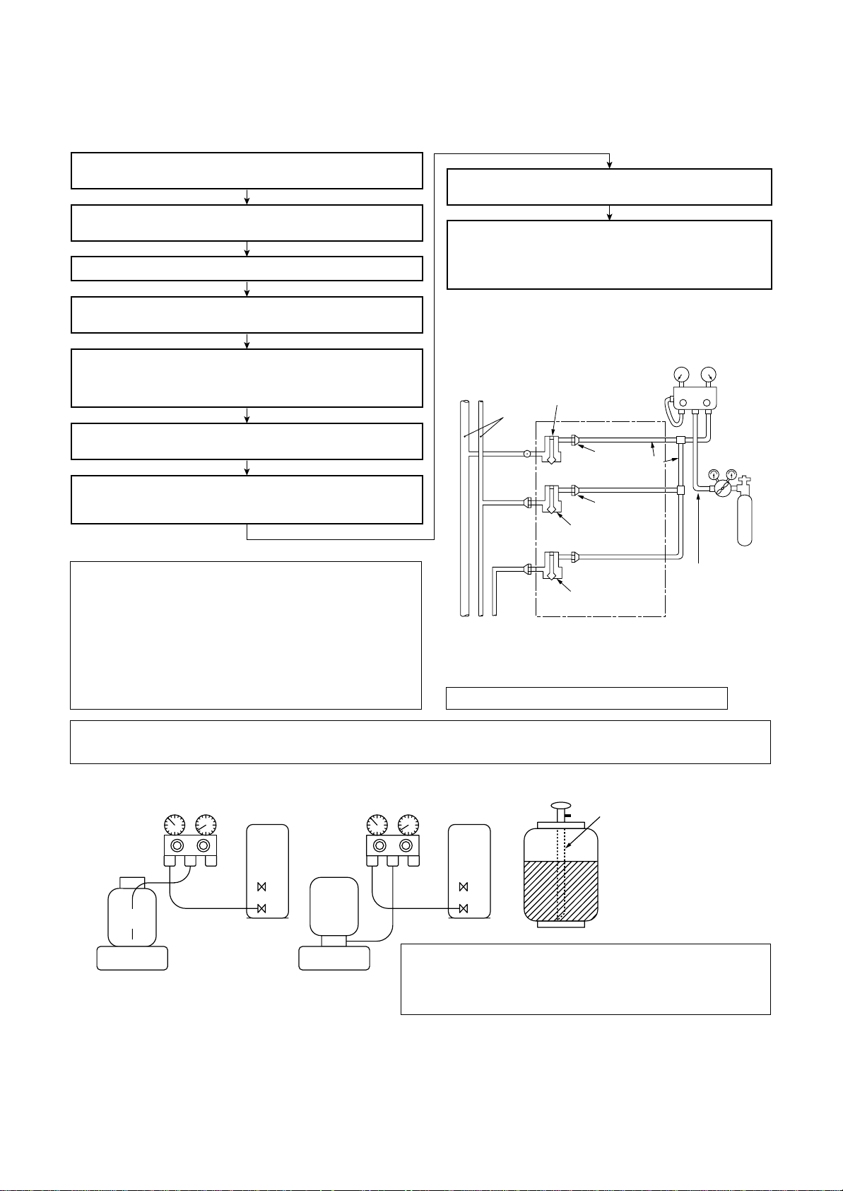
5. Recharge of Refrigerant
VLV
H
Connected to
indoor unit
Main
pipe
Valve fully closed
(gas side)
Center unit
Low-
pressure gauge
High-
pressure gauge
Gauge
manifold
Brazed
Service
port
Service port
Ø6.4
Copper pipe
Ø6.4
Copper pipe
Fully
tightened
Fully
tightened
Reducing
valve
Nitrogen
gas
Valve fully closed
(liquid side)
Valve fully closed
(balance)
Connected to other
terminal units
When recharge of the refrigerant is required, charge the new refrigerant with the specified amount in the
procedure as described below .
Recover the refrigerant and check there is no refrigerant in the
equipment.
Connect the charge hose to the packed valve service ports at gas
side, liquid side, and balance side of the outdoor unit.
Connect the charge hose to vacuum pump adaptor.
Leave it as it is for 1 to 2 minutes and check the indicator of
the compound gauge does not return.
Set the refrigerant cylinder on the electron balance, connect
the charge hose to connecting ports of the cylinder and the
electron gauge, and then charge the liquid refrigerant from the
service port at liquid side. (Shield with the gauge manifold so
that refrigerant does not flow to gas side.)
Open the packed valves of the balance pipe fully at liquid and gas
sides, and then return the valve at gas side a little to the closed side.
Open fully PMV of the outdoor unit.
• Turn on power of the outdoor unit.
• Short CN30 on I/F P.C. board of the outdoor unit.
•
Turn off power of the outdoor unit within 2 minutes after short-circuiting.
Open fully the handle Low of the gauge manifold, and then turn on
the power of vacuum pump for vacuuming.
When the pressure has lowered until indication of the compound
gauge pointed -0.1MPa (-76cmHg), open fully the handle Low and
turn off the power of vacuum pump.
Never charge the refrigerant ov er the specified amount.
Q
Do not charge the additional refrigerant.
R
If charging refrigerant additionally when refrigerant gas
leaks, the refrigerant composition in the refrigerating
cycle changes resulted in change of air conditioner
characteristics or refrigerant over the specified standard amount is charged and an abnormal high
pressure is applied to the inside of the refrigerating
cycle resulted in cause of breakage or injury.
(Charge the refrigerant as below.)
4mm-hexagonal wrench is required.
6. Environment
Use “Vacuum pump method” for an air purge (Discharge of air in the connecting pipe) in installation time.
• Do not discharge flon gas into the air to protect the earth environment.
• Using the vacuum pump method, clear the remained air (Nitrogen, etc.) in the unit. If the air remains, the
Set the equipment so that liquid refrigerant can be charged.
Q
When using a cylinder with siphon pipe, liquid can be charged without inversing the cylinder.
R
[ Cylinder with siphon ] [ Cylinder without siphon ]
Refrigerant
cylinder
Electronic
balance
Gauge manifold
OUTDOOR unit
Electronic
balance
Gauge manifold
cylinder
Refrigerant
OUTDOOR unit
Siphon
R410A refrigerant is consisted with HFC mixed refrigerant.
Therefore if the refrigerant gas is charged, the composition
of the charged refrigerant changes and characteristics of
pressure in the refrigerating cycle becomes abnormally high and an injury and others are caused due to burst.
the equipment changes.
7
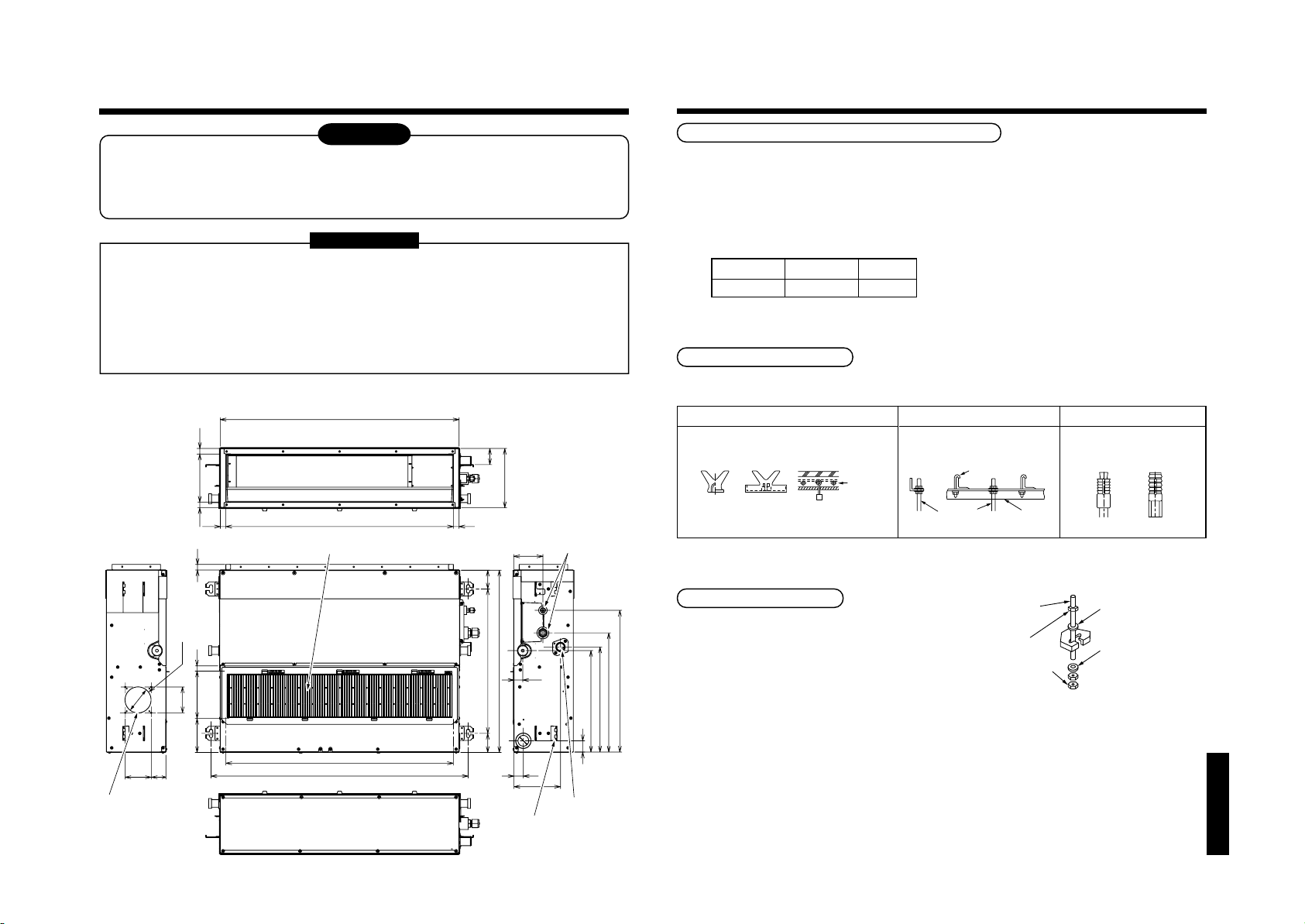
Page 8
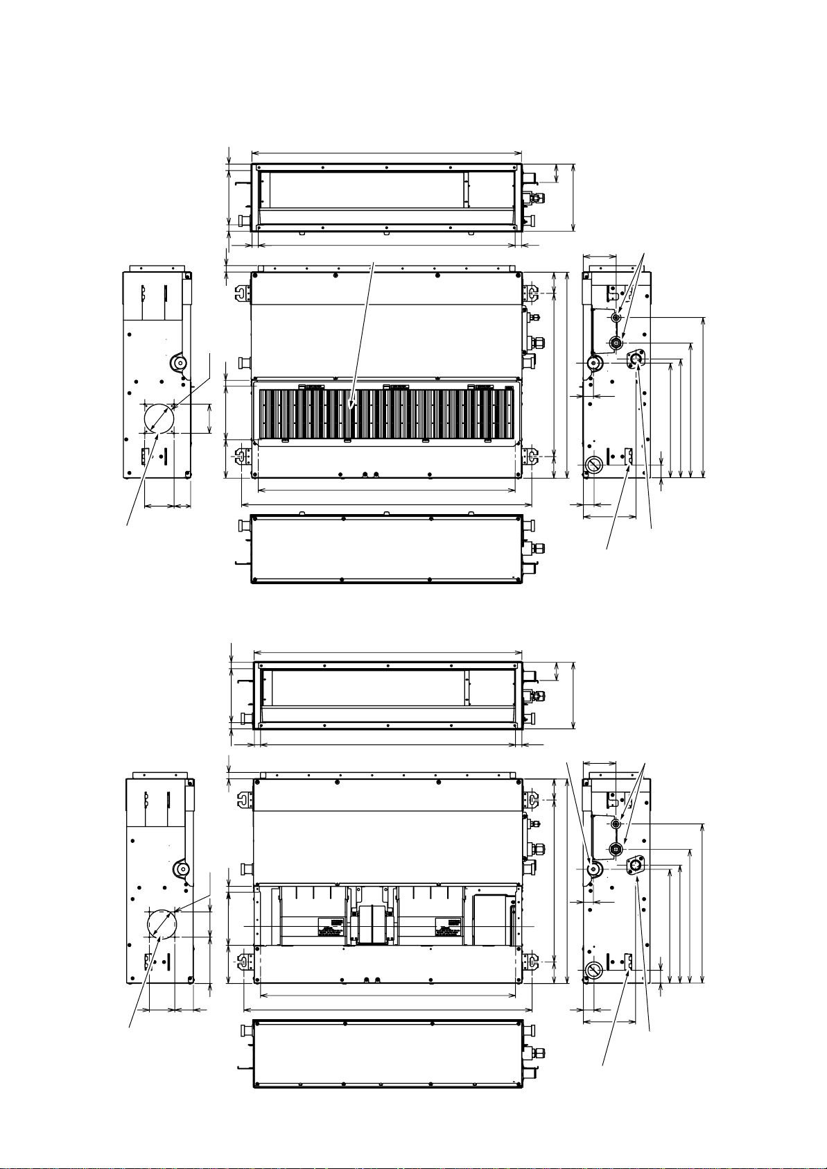
1. CONSTRUCTION VIEWS (EXTERNAL VIEWS)
MMD-AP0071SPH(-K), AP0091SPH(-K), AP0121SPH(-K), AP0151SPH(-K), AP0181SPH(-K)
21
845
57
Ø92
59
80
Fresh air inlet
(knock-out hole)
168
4-Ø4
80
(inside)
21
21
20
19
168
120
Air filter
805
910
210
21803 (inside)
67
511
645
67
Refrigerant piping
103
31
33
163
372
502
422
359
40
Drain-up port
Hung-up plate
MMD-AP0071SPH-C, AP0091SPH-C, AP0121SPH-C, AP0151SPH-C, AP0181SPH-C,
MMD-AP0071SH-C, AP0091SH-C, AP0121SH-C, AP0151SH-C, AP0181SH-C
845
57
210
168(inside)
Ø92
Fresh air inlet
(knock-out hole)
21
21 21
20
19
4-Ø4
168
146 80
120
5980
803 (inside)
805
910
21
Natural drain port
67
511
67
Hang-up plate
645
Refrigerant
piping
103
31
33
163
Drain-up port
(SPH model only)
359
40
372
422
502
8
Page 9
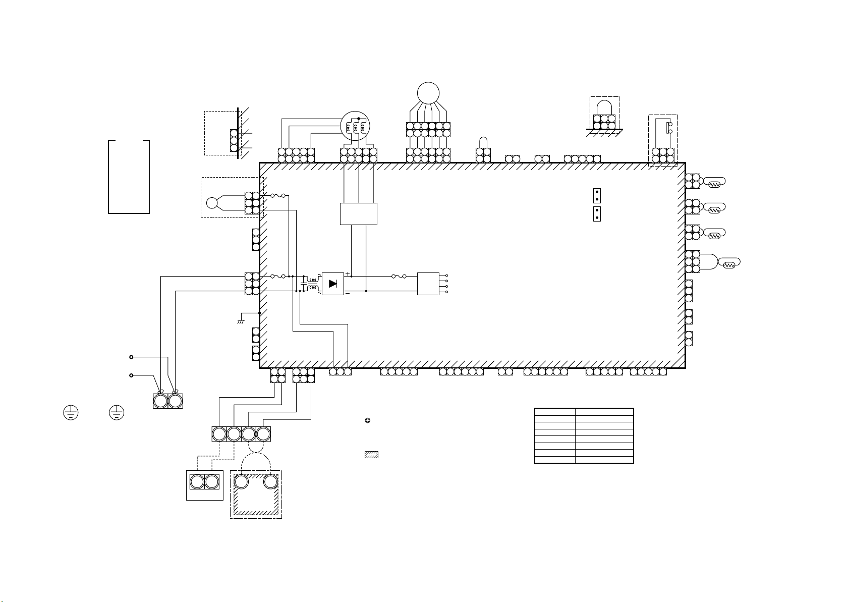
9
Flow
Selector unit
Earth screw
indication
RED : RED
WHI : WHITE
YEL : YELLOW
BLU : BLUE
BLK : BLACK
GRY : GRAY
PNK : PINK
ORN : ORANGE
BRN : BRWN
GRN : GREEN
Closed-end
connector
Indoor unit
Earth screw
Color
WHI
RED
220-240V~, 50Hz
R(L) S(N)
Power supply
220V~, 60Hz
Non Drain pump type
("SH" T ype)
CN68
(BLU)
1
3
Drain pump type
("SPH" T ype)
DM
U1 U2
RED
WHI
CN44
(BRW)
CN68
(BLU)
1
1
3
BLK
A B
2. WIRING DIAGRAM
MMD-AP0071SPH(SH), AP0091SPH(SH), AP0121SPH(SH), AP0151SPH(SH), AP0181SPH(SH)
Non Drain pump type
PMV
FM
1
2
3
4
6
6
CN333
5
3
(WHI)
54 3
32 1
circuit
CN309
(YEL)
1. indicates the terminal bolock.
Letter at inside indicates the terminal number.
2. A dotted line and broken line indicate the
wiring at side
Fuse
T3.15A
250V~
CN50
(WHI)
1 2 3 4 5
1 2 3 4 5 6
1
BLU
CN41
(BLU)
1 233
BLK
CN334
(WHI)
BLK
1
1
Motor drive
31
5 4 1
5
RY302
313
1
CN304
(GRY)
3
Fuse
T6.3A
250V~
1
3
CN67
(BLK)
P301
1
CN66
(WHI)
2
1
CN40
(BLU)
2
11221
BLU
3. indicate a control P.C. board.
5
4
2
3
3
Power
supply
circuit
1
4
(External static pressure setup)
2
5
CN82
1 2
(BLU)
1 2
5 3
6
CN112
(WHI)
DC20V
DC15V
DC12V
DC7V
CN61
(YEL)
1 2 3 4 5 6
1 2
CN111
CN110
(WHI)
Control P.C. board
for undoor unit
CN32
(WHI)
1 2
1 2 3 4 5 6
Fan drive
1 2 1 2
(WHI)
MCC-1402
CN60
(WHI)
Option
Symbol
FM
TA
TC1,TC2,TCJ
RY302
PMV
DM
FS
("SH" T ype)
1 3
1 2 3
CN33
(WHI)
4 5
CN71
(CHK)
CN72
(DISP)
CN81
(BLK)
1 2 3 4 5
Parts name
Fan motor
Indoor temp sensor
Temp sensor
Drain control relay
Pulse motor valve
Drain pump motor
Float switch
Drain pump type
("SPH" T ype)
CN34
(RED)
CN20
(BLU)
1 2 3 4 5
1 3
1 2 3
CN104
(YEL)
CN102
(RED)
CN101
(BLK)
CN100
(BRW)
CN80
(GRN)
CN73
(RED)
CN70
(WHI)
FS
CN34
(RED)
212
212
1
2
131
1
2
3
1
2
1
2
1
1
1
2
3
PNL
EXCT
TA
TCJ
TC2
TC1
U1 U2
Outdoor unit
A B
Wired remote
controller
Page 10
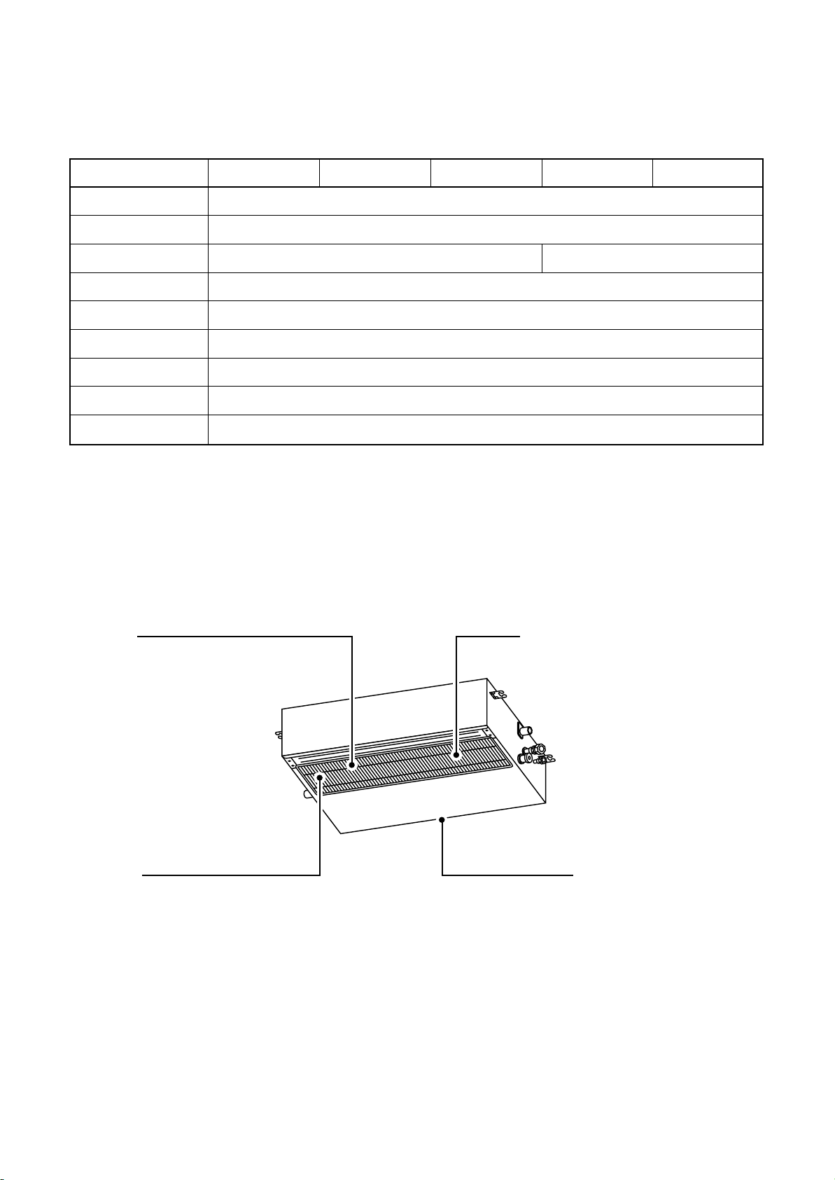
3. PARTS RATING
3-1. Parts Rating
Model MMD-
Fan motor
Pulse motor
Pulse motor valve
Drain pump motor ∗
Float switch ∗
TA sensor
TC1 sensor
TC2 sensor
TCJ sensor
∗ “SPH” series only
AP0071SPH AP0091SPH AP0121SPH AP0151SPH AP0181SPH
SWF-280-60-1
EDM-MD12TF-3
EDM-B25YGTF EDM-B40YGTF
ADP-1409
FS-0218-102
Lead wire length : 1558mm Vinyl tube
Ø4 size lead wire length : 1200mm Vinyl tube (Blue)
Ø6 size lead wire length : 1200mm Vinyl tube (Black)
Ø6 size lead wire length : 1200mm Vinyl tube (Red)
3-2. Name of Each Part
Air inlet
Suction duct is connected.
Air filter
(Air filter is not provided to some models in the series.)
Earth screw
It is included in the electric parts box.
Air outlet
Discharge duct is connected.
10
Page 11
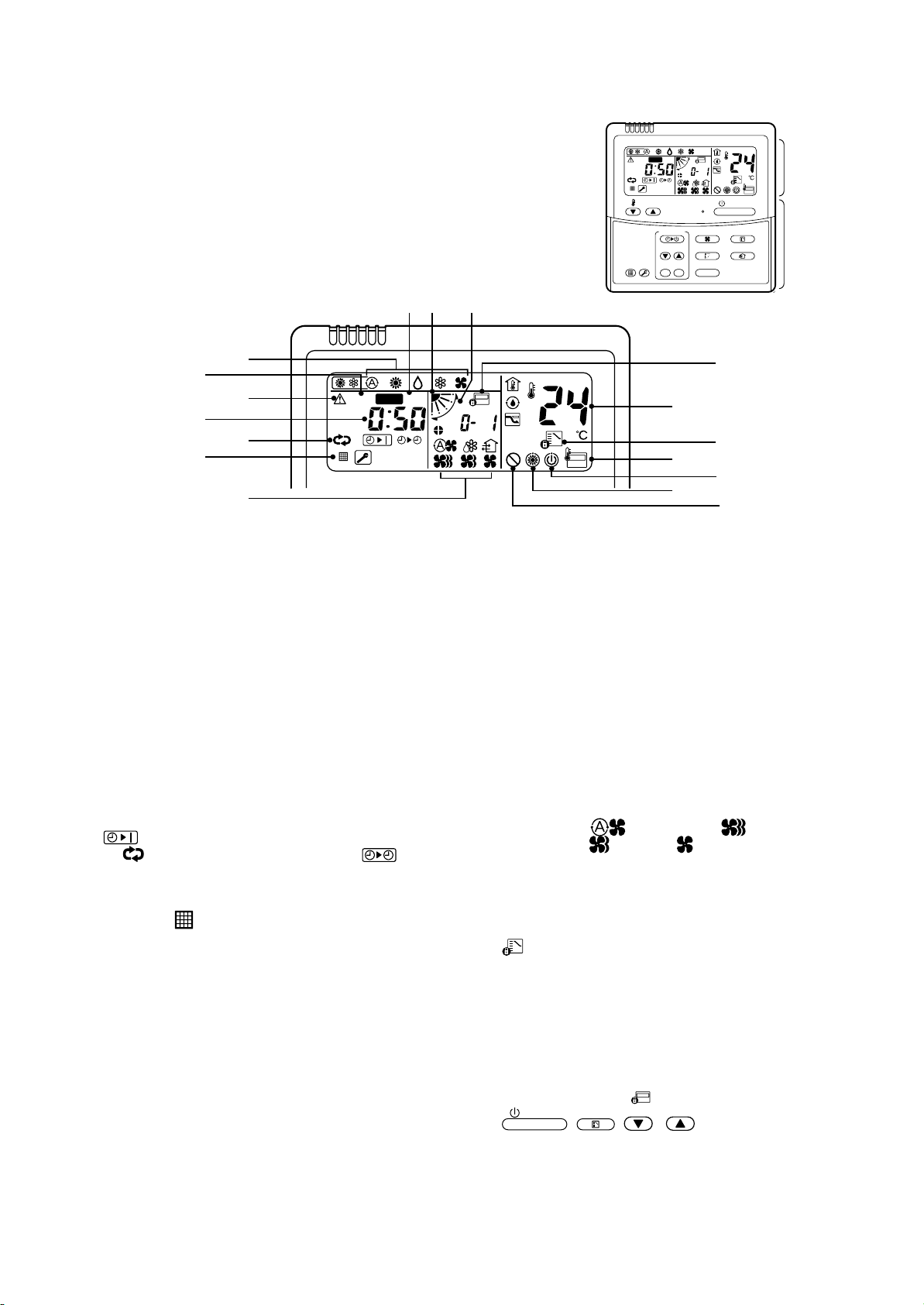
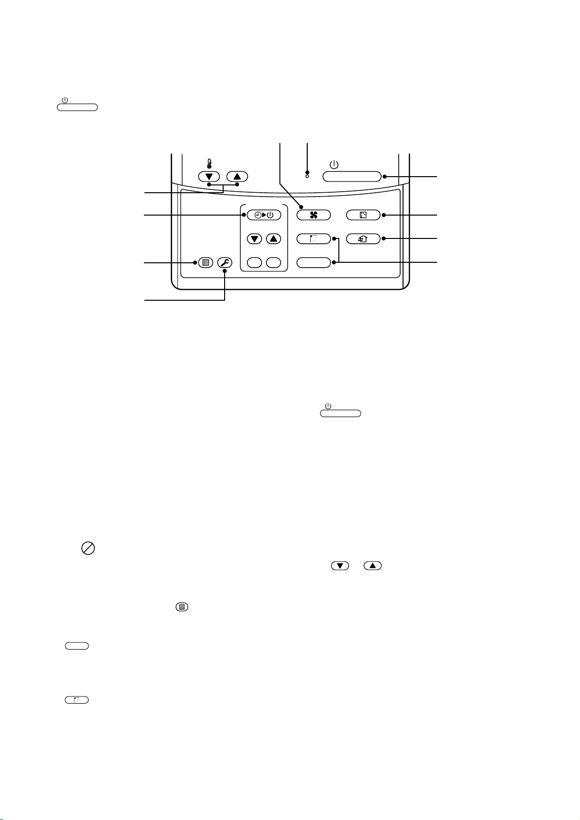
3-3. Parts Name of Remote Controller
ON / OFF
Display section
In the display example, all indicators are displayed for the explanation.
In reality only, the selected contents are indicated.
• When turning on the leak breaker at the first time, [SET DATA] flashes
on the display part of the remote controller. While this display is flashing,
the model is being automatically confirmed. Accordingly, wait for a while
after [SET DATA] display has disappeared, and then use the remote
controller.
78 9
2
1
4
3
5
SET
H
DATA
SETTING
TEST
UNIT No.
R.C. No.
CODE No.
6
15
1
SET DATA display
Displayed during setup of the timer.
2
Operation mode select display
The selected operation mode is displayed.
3
CHECK display
Displayed while the protective device works or a
trouble occurs.
4
Timer time display
Time of the timer is displayed.
(When a trouble occurs, the check code is displayed.)
5
Timer SETIN setup display
When pushing the Timer SETIN button, the
display of the timer is selected in order of [OFF]
→ [OFF] repeat OFF timer → [ON]
→ No display.
6
Filter display
If “FILTER ” is displayed, clean the air filter.
7
TEST run display
Displayed during a test run.
8
Flap position display
(for 4-Way Air Discharge Cassette T ype and
Under Ceiling Type model only)
Displays flap position.
9
SWING display
Displayed during up/down movement of the flap.
10
Set up temperature display
The selected set up temp. is displayed.
11
Remote controller sensor display
Displayed while the sensor of the remote
controller is used.
12
PRE-HEAT display
Displayed when the heating operation starts or
defrost operation is carried out.
While this indication is displayed, the indoor fan
stops or the mode enters in LOW.
13
Operation ready display
Displayed when cooling or heating operation is
impossible because the outdoor temperature goes
out of the operable range.
14
No function display
Displayed if there is no function even if the button is
pushed.
15
Air volume select display
The selected air volume mode is displayed.
(AUTO)
(MED.) (LOW)
In the Concealed Duct High Static Pressure type
models, [HIGH] only is displayed for the air speed.
16
Mode select control display
Displayed when pushing “Operation mode select
” button while the operation mode is fixed to
heating or cooling by the system manager of the air
conditioner.
17
Central control display
Displayed when using the remote controller together with the central control remote controller,
etc.
If Remote controller is prohibited at the
centralcontrol side,
the change is not accepted.
(The contents available to be set up on the remote
controller differ according to the central control
mode. For details, refer to Owner’s Manual of the
central control remote controller.)
CODE No.
ON / OFF
FAN
MODE
SWING/FIXTIME
VENT
UNITSET CL
Display
section
Operation
section
FILTER
RESET
SET
DATA
H
TEMP.
TEST
SETTING
TEST
TIMER SET
UNIT No.
R.C. No.
17
10
16
11
13
12
14
(HIGH)
flashes when operating
MODE
,
, / buttons and
11
Page 12
Operation section
ON / OFF
Push each button to select a desired operation.
• The details of the operation needs to be set up once, afterward, the air conditioner can be used by pushing
ON / OFF
button only.
1
7
TEMP.
10
2
FIL TER
TEST
RESET
5
3
1
Air volume select button
Selects the desired air volume mode.
The Concealed Duct High Static Pressure type
models cannot be operated.
2
Timer set button
TIMER SET button is used when the timer is set
up.
3
Check button
The CHECK button is used for the check operation. During normal operation, do not use this
button.
4
Fan button
FAN button is used when a fan which is sold on
the market or etc. is connected.
• If is displayed on the remote controller
when pushing the FAN button, a fan is not
connected.
TIMER SET
ON / OFF
8
FAN
SWING/FIXTIME
MODE
VENT
9
4
UNITSET CL
6
7
Operation lamp
Lamp is lit during the operation. Lamp is off
when stopped.
Although it flashes when operating the protection
device or abnormal time.
8
When the button is pushed, the operation starts,
and it stops by pushing the button again.
When the operation has stopped, the operation
lamp and all the displays disappear.
9
Operation select button
Selects desired operation mode.
10
Set up temperature button
Adjusts the room temperature.
Set the desired set temperature by pushing
button
or .
5
Filter reset button
Resets (Erases) “FILTER ” display.
6
Wind direction and Swing
UNIT
:
If the multiple indoor units are operated by only
one remote controller, select the units when the
air direction is adjusted.
SWING/FIX
:
Set up the auto swing and angle of the flap.
• This function is not provided to Concealed
Duct Standard Type, High Static Pressure
Type, Floor standing Cabinet Type, Floor
Standing Concealed Type, or Slim Duct Type.
OPTION :
Remote controller sensor
UUsually the TEMP. sensor of the indoor unit senses
the temperature. The temperature on the surrounding of the remote controller can also be sensed.
For details, contact the dealer from which y ou have
purchased the air conditioner.
• In case that one remote controller controls the
multiple indoor units, the setup operation is
unavailab le in g roup control.
12
Page 13
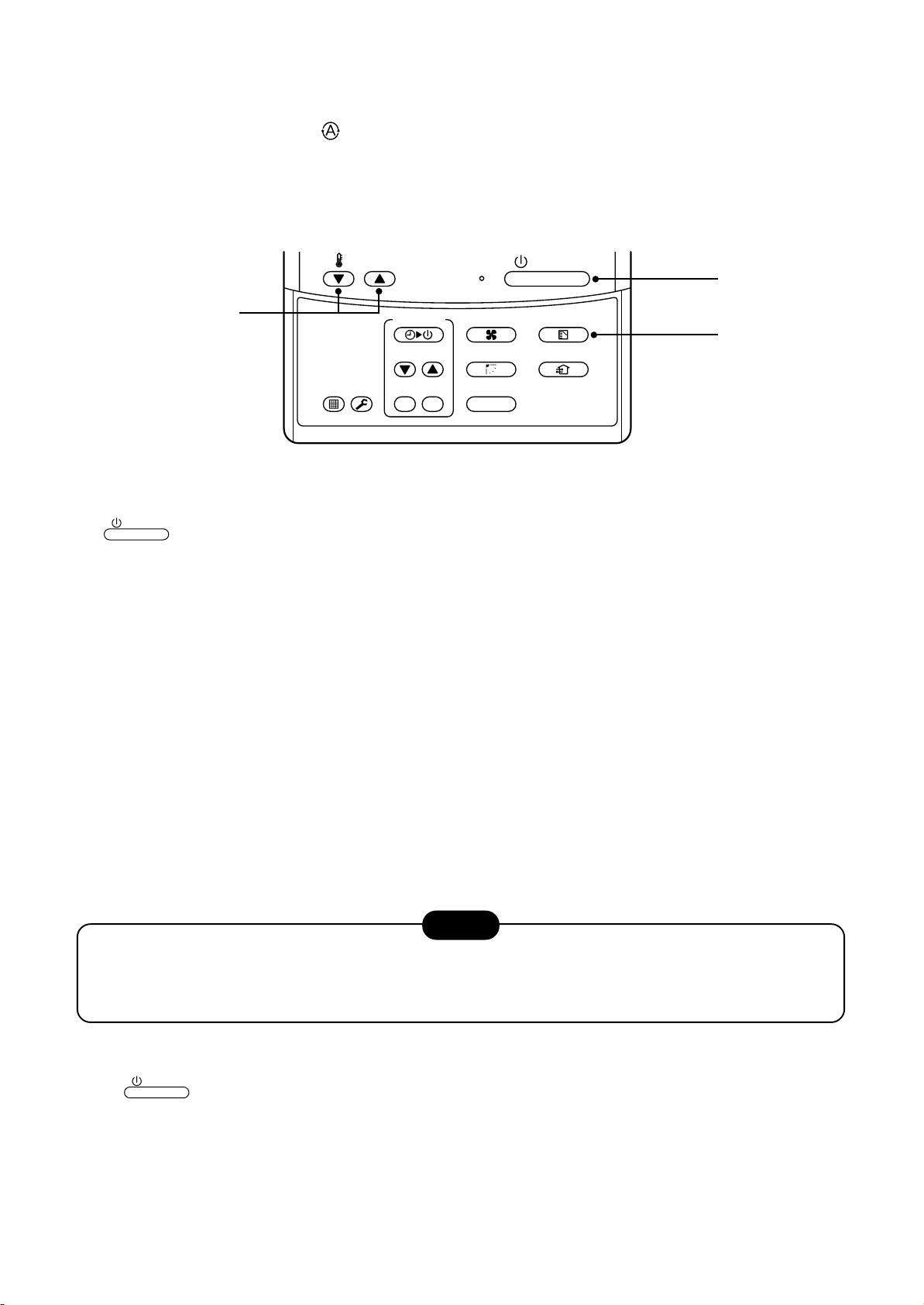
3-4. Correct Usage
LOW MED. HIGH
AUTO
When you use the air conditioner for the first time or when you change the SET DATA value, follow the procedure below. From the next time, the operation displayed on the remote controller will start by pushing the
ON / OFF
Preparation
Turn on the main power switch and/or the leakage breaker.
• When the power supply is turned on, a partition line is displayed on the display part of the remote controller .
* After the power supply is turned on, the remote controller does not accept an operation for approx. 1 minute,
but it is not a f ailure.
• While using the air conditioner, operate it only with
button only.
switch and the leak breaker.
REQUIREMENT
ON / OFF
button without turning off the main power
TEMP.
ON / OFF
1
4
TIMER SET
FIL TER
TEST
RESET
1
Push
The operation lamp goes on, and the operation starts.
2
Select an operation mode with the “MODE” button.
One push of the button, and the display
changes in the order shown on the right.
• In HEAT mode, if the room temperature reaches to
the set temperature, the outdoor unit stops and the air
flow becomes LOW and the air volume decreases.
• In the defrost mode, the fan stops so that cool air is not discharged and PRE-DEF is displayed.
3
Select air volume with “ ” button.
One push of the button, and the display
changes in the order shown on the right.
ON / OFF
button.
FAN
SWING/FIXTIME
UNITSET CL
MODE
VENT
DRY COOL FAN
HEAT DRY COOL FAN
3
2
Cooling only model
Heat-pump model
(Dehumidity)
• When air volume is “AUTO ”, air volume differs according to the temperature difference between set
temp. and room temp.
• In DRY mode, “AUTO ” is displayed and the air volume is LOW .
• In heating operation, if the room temperature is not heated sufficiently with VOLUME “LOW ” operation,
select “MED. ” or “HIGH ” operation.
4
Determine the set up temperature by pushing the “TEMP. TEMP. ” or “TEMP. ” button.
Stop
Push
The operation lamp goes off, and the operation stops.
ON / OFF
button.
13
Page 14
3-5. Automatic Operation (Super Heat Recovery Type Only)
When you set the air conditioner in mode or switch over from AUTO operation because of some settings
change, it will automatically select either cooling, heating, or fan only operation depending on the indoor temperature.
TEMP.
ON / OFF
1
3
FIL TER
RESET
TIMER SET
TEST
FAN
SWING/FIXTIME
UNITSET CL
Start
ON / OFF
1
Push this button to start the air conditioner.
2
Mode select button (MODE)
Select Auto.
3
Temperature button
Set the desired temperature.
• In case of cooling, start the operation after approx. 1 minute.
• In case of heating, the operation mode is selected in accordance with the room temperature and operation
starts after approximately 3 to 5 minutes.
• When you select the Auto mode, it is unnecessary to set the fan speed.
The FAN speed display will show AUTO and the fan speed will be automatically controlled.
• After the heating operation has stopped, FAN operation may continue for approx. 30 seconds.
• When the room temperature reaches the set temperature and the outdoor unit stops, the super low wind is
discharged and the air volume decreases excessively .
During defrost operation, the fan stops so that cool air is not discharged and “HEAT READY” is displayed.
• If the Auto mode is uncomfortable, y ou can select the desired conditions manually.
button
MODE
VENT
2
NOTE
When restarting the operation after stop
• When restarting the operation immediately after stop, the air conditioner does not operate for approx. 3
minutes to protect the machine.
Stop
Push
Push this button again to stop the air conditioner.
ON / OFF
button.
14
Page 15
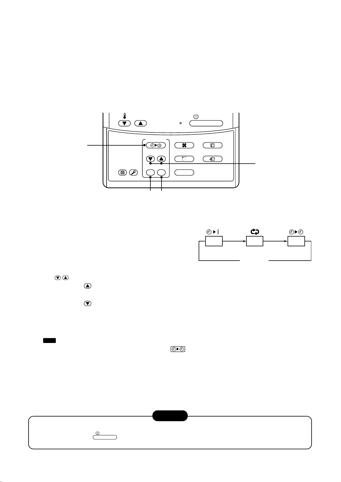
3-6. TIMER Operation
OFF
(OFF timer) (Repeat OFF timer)
No display
(ON timer)
OFF ON
A type of timer operation can be selected from the following three types .
OFF timer : The operation stops when the time of timer has reached the set time.
Repeat OFF timer : Every time, the operation stops after the set time has passed.
ON timer : The operation starts when the time of timer has reached the set time.
Timer operation
1
FIL TER
RESET
1
Push TIMER SET button.
• The timer display (type) changes for every
push of the button.
• SET TIME and timer time displays flash.
2
Push
TIME
to select “SET TIME”.
TEMP.
TEST
TIMER SET
3
4
ON / OFF
FAN
SWING/FIXTIME
UNITSET CL
MODE
VENT
2
For every push of button, the set time increases in the unit of 0.5 hr (30 minutes).
The maximum set time is 72.0 hr.
For every push of button, the set time decreases in the unit of 0.5 hr (30 minutes).
The minimum set time is 0.5 hr.
3
Push SET button.
•
display disappears and timer time display goes on.
SETTING
(When ON timer is activated, timer time, ON timer are displayed and other displays disappear.)
Cancel of timer operation
4
Push CL button.
• TIMER display disappears.
NOTICE
• When the operation stops after the timer reached the preset time, the Repeat OFF timer resumes the
operation by pushing
set time.
ON / OFF
button and stops the operation after the time of the timer has reached the
15
Page 16
3-7. Information
Confirmation before operation
• Turn on the power switch 12 hours before starting
the operation.
• Make sure whether earth wire is connected.
• Make sure the air filter is connected to the indoor
unit.
Heating capacity
• A heat pump system which absorbs heat from
outside of the room and then discharges heat into
the room is adopted for heating. If the outside
temperature falls, the heating capacity decreases .
• When the outside temperature is too low, it is
recommended to use this air conditioner together
with other heating equipment.
Defrost during heating operation
• In heating operation, if there is frost on the outdoor
unit, the operation changes automatically to the
defrost operation (Approx. 2 to 10 minutes) to
increase the heating efficiency.
• During defrost operation, the fan of the indoor unit
stops.
3-minutes protection
Protective device (High pressure switch)
This device stops automatically an operation when
excessive force is applied on the air conditioner.
If the protective device works , the operation stops
and the operation lamp flashes.
When the protective device w orks, the indication
and the check code are displayed on the display
section of the remote controller. In the following
cases, the protective device may work.
In cooling operation
• The suction port or discharge port of the outdoor
unit is closed.
• A strong wind continuously blows to the discharge
port of the outdoor unit.
In heating operation
• Dust or waste adheres excessively to air filter of
the indoor unit.
• The discharge port of the indoor unit is closed.
If the protective device works, turn off the main
power switch, solve the cause, and then start the
operation again.
TEST
• When restarting the operation just after the
operation has been stopped or the main power
switch has turned on, the outdoor unit does not
work for approx. 3 minutes in order to protect the
air conditioner.
Power failure
• If a power failure occurred during operation, all
operations stop.
• When the power is returned after a power failure,
the operation lamp notifies the power-ON by
flashing operation lamp on the remote controller.
• When restarting the operation, push
button again.
ON / OFF
Fan rotation in stopped unit
• In heating operation even in the stopped indoor
unit, the fan rotates once for several minutes per
approx. an hour when the other indoor unit is
operating to protect the air conditioner.
Cooling/Heating operation of Super
Modular Multi system air conditioner
• Although each indoor unit can be individually
controlled in the Super Modular Multi system air
conditioner, the cooling oper ation and the heating
operation cannot be simultaneously performed in
the multiple indoor units which are connected to
an outdoor unit.
• If the cooling operation and the heating operation
are simultaneously performed, the indoor unit
which executes cooling operation stops, and on
the operation section lights up. On the other hand,
the indoor unit which executes heating operation
continues running. In a case that the manager of
the air conditioner has fixed the operation to
cooling or heating, an operation other than that set
up is unavailab le. If an operation other than that
set up is executed, on the operation section
lights up and the operation stops.
Characteristics of heating operation
• The wind is not out just after starting an operation.
The hot wind starts to blow 3 to 5 minutes after
(Time differs according to indoor/outdoor temperature.) the indoor heat exchanger has warmed up.
• During operation, the outdoor unit may stop if the
outside temperature rises.
16
Page 17
3-8. Air Conditioner Operations and Performance
3 minutes protection function
3-minutes protection function prevents the air conditioner from starting for initial 3 minutes after the main power
switch/circuit breaker is turned on f or re-starting the air conditioner .
Power failure
P o wer failure during operation will stop the unit completely.
• To restart the operation, push the START/STOP button on the remote controller.
• Lightning or a wireless car telephone operating nearby may cause the unit to malfunction. Turn off the main
power switch or circuit breaker and then turn them on again. Push the START/STOP button on the remote
controller to restart.
Heating characteristics
Preheating operation
The air conditioner will not deliver warm air immediately after it is turned on. Warm air will start to flow out after
approximately 5 minutes when the indoor heat exchanger warmed up.
Warm air control (In heating operation)
When the room temperature reaches the set temperature, the fan speed is automatically reduced to prevent to
blow cold draft. At this time, the outdoor unit will stop.
Defrosting operation
If the outdoor unit is frosted during the heating operation, defrosting starts automatically (for approximately
2 to 10 minutes) to maintain the heating capacity.
• The fans in both indoor and outdoor units will stop during the defrosting operation.
• During the defrosting operation, the defrosted water will be drained from the bottom plate of the outdoor unit.
Heating capacity
In the heating operation, the heat is absorbed from the outside and brought into the room. This way of heating
is called heat pump system. When the outside temperature is too low, it is recommended to use another heating
apparatus in combination with the air conditioner.
Attention to snowfall and freeze on the outdoor unit
• In snowy areas, the air inlet and air outlet of the outdoor unit are often covered with snow or froz en up.
If snow or freeze on the outdoor unit is left as it is, it may cause machine failure or poor warming.
• In cold areas, pay attention to the drain hose so that it perfectly drains water without water remaining inside for
freeze prevention. If water freezes in the drain hose or inside the outdoor unit, it may cause machine failure or
poor warming.
Air conditioner operating conditions
For proper performance, operate the air conditioner under the following temperature conditions:
Cooling operation
Dry operation
Outdoor temperature : –5°C to 43°C (Dry valve temp.)
Room temperature : 21°C to 32°C (Dry valve temp.), 15°C to 24°C (Wet valve temp.)
CAUTION
Outdoor temperature : 15°C to 21°C (Dry valve temp.), –15°C to 15.5°C (Wet valve temp.)
Room temperature : 15°C to 28°C (Dry valve temp.)
Room relative humidity – less than 80 %. If the air conditioner operates
in excess of this figure, the surface of the air conditioner may cause dewing.
If air conditioner is used outside of the above conditions, safety protection may work.
17
Page 18
3-9. When the Following Symptoms are Found
Check the points described below before asking repair servicing.
Symptom
Outdoor unit • White misty cold air
or water is out.
• Sometimes, noise
“Pushu !” is heard.
Indoor unit •“Swish” sound is
heard sometimes.
• Slight “Pishi!” sound
is heard.
• Discharge air smells.
• The operation lamp
flashes
•“STANDBY”
indication is lit.
Check again.
• Sound or cool air is
output from the
stand by indoor unit.
• When power of the
air conditioner is
turned on, “Ticktock”
sound is heard.
Cause
• Fan of the outdoor unit stops automatically and performs defrost
operation.
• Solenoid valve works when defrost operation starts or finishes.
• When the operation has started, dur ing the operation, or immediately
after the operation has stopped, a sound such as water flows may be
heard, and the operation sound may become larger for 2 or 3 minutes
immediately after the operation has started. They are flowing sound of
refrigerant or draining sound of dehumidifier.
• This is sound generated when heat exchanger, etc. expand and
contract slightly due to change of temperature.
• Various smell such as one of wall, carpet, clothes, cigarette, or
cosmetics adhere to the air conditioner.
• Flashes when power is turned on again after power failure, or when
power switch is turned on.
• When cooling operation cannot be performed because another indoor
unit performs heating operation.
• When the manager of the air conditioner has fixed the operation to
COOL or HEAT, and an operation contrary to the setup operation is
performed.
• When fan operation stopped to prevent discharge of hot air.
• Since refrigerant is flowed temporarily to prevent stay of oil or
refrigerant in the stand by indoor unit, sound of flowing refrigerant,
“Kyururu” or “Shaa” may be heard or white steam when other indoor
unit operates in HEAT mode, and cold air in COOL mode may be
blow-out.
• Sound is generated when the expansion valve operates when power
has been turned on.
Operates or stops automatically.
Does not operate.
Silent
Air is not cooled or warmed sufficiently.
It is not a failure.
It’s strange.
• Is the timer “ON” or “OFF”?
• Is it a power failure?
• Is the power switch turned off?
• Is the power fuse or breaker blown?
• Has the protective device operated? (The operation lamp goes on.)
• Is the timer “ON”? (The operation lamp goes on.)
• Are COOL and HEAT selected simultaneously? (“STANDBY” indication is lit on the display column of the remote controller.)
• Is the suction port or discharge port of the outdoor unit obstructed?
• Are any door or window open?
• Is the air filter clogged with dust?
• Is discharge louver of the indoor unit set at appropriate position?
• Is air selection set to “LOW” “MED”, and is the operation mode set to
“FAN”?
• Is the setup temp. the appropr iate temperature?
• Are COOL and HEAT selected simultaneously? (“STANDBY” indication is lit on the display column of the remote controller.)
When the following symptoms are found, stop the operation immediately, turn off the power switch, and contact
the dealer which you have purchased the air conditioner.
• Activation of switch is unstable.
• Fuse or breaker is blown periodically.
• Foreign matters or water entered by mistake.
• When if activation cause of the protective device has been removed, the operation is not performed.
• Other unusual status occurred.
18
Page 19
Accessory parts
3-10. Installation Manual
19
H Accessory parts
Part name
Installation Manual
Insulating pipe
Washer
Hose band
Flexible hose
Heat insulator
1
PRECAUTIONS FOR SAFETY
• Ensure that all Local, National and International regulations are satisfied.
• Read this “PRECAUTIONS FOR SAFETY” carefully before Installation.
• The precautions described below include the important items regarding safety. Observe them without fail.
• After the installation work, perform a trial operation to check for any problem.
Follow the Owner’s Manual to explain how to use and maintain the unit to the customer.
• Turn off the main power supply switch (or breaker) before the unit maintenance.
• Ask the customer to keep the Installation Manual together with the Owner’s Manual.
Q’ty
1
2
8
1
1
1
CAUTION New Refrigerant Air Conditioner Installation
• THIS AIR CONDITIONER ADOPTS THE NEW HFC REFRIGERANT (R410A) WHICH DOES NOT
DESTROY OZONE LAYER.
The characteristics of R410A refrigerant are ; easy to absorb water, oxidizing membrane or oil, and its
pressure is approx. 1.6 times higher than that of refrigerant R22. Accompanied with the new refrigerant,
refrigerating oil has also been changed. Therefore, during installation work, be sure that water, dust,
former refrigerant, or refrigerating oil does not enter the refrigerating cycle.
To prevent charging an incorrect refrigerant and refrigerating oil, the sizes of connecting sections of
charging port of the main unit and installation tools are charged from those for the conventional
refrigerant.
Accordingly the exclusive tools are required for the new refrigerant (R410A).
For connecting pipes, use new and clean piping designed for R410A, and please care so that water or
dust does not enter. Moreover, do not use the existing piping because there are problems with pressureresistance force and impurity in it.
Shape
This manual
M10 × Ø34
——
Usage
(Be sure to hand over to customers)
For insulating pipe connecting section
For hanging down the unit
For connecting drain pipe
For adjustment of drain pipe centering
For insulating drain connecting section
CAUTION To Disconnect the Appliance from Main Power Supply.
This appliance must be connected to the main power supply by means of a switch with a contact separation of
at least 3 mm.
WARNING
• Ask an authorized dealer or qualified installation professional to install/maintain the air
conditioner.
Inappropriate installation may result in water leakage, electric shock or fire.
• Turn off the main power supply switch or breaker before attempting any electrical work.
Make sure all power switches are off. Failure to do so may cause electric shock.
• Connect the connecting wire correctly.
If the connecting wire is connected in a wrong way, electric parts may be damaged.
• When moving the air conditioner for the installation into another place, be very careful not to
enter any gaseous matter other than the specified refrigerant into the refrigeration cycle.
If air or any other gas is mixed in the refrigerant, the gas pressure in the refrigeration cycle becomes
abnormally high and it as a result causes pipe burst and injuries on persons.
• Do not modify this unit by removing any of the safety guards or by by-passing any of the safety
interlock switches.
• Exposure of unit to water or other moisture before installation may cause a short-circuit of
electrical parts.
Do not store it in a wet basement or expose to rain or water.
• After unpacking the unit, examine it carefully if there are possible damage.
• Do not install in a place that might increase the vibration of the unit.
• To avoid personal injury (with sharp edges), be careful when handling parts.
• Perform installation work properly according to the Installation Manual.
Inappropriate installation may result in water leakage, electric shock or fire.
• When the air conditioner is installed in a small room, provide appropriate measures to ensure that
the concentration of refrigerant leakage occur in the room does not exceed the critical level.
• Install the air conditioner securely in a location where the base can sustain the weight
adequately.
• Perform the specified installation work to guard against an earthquake.
If the air conditioner is not installed appropriately, accidents may occur due to the falling unit.
• If refrigerant gas has leaked during the installation work, ventilate the room immediately.
If the leaked refrigerant gas comes in contact with fire, noxious gas may generate.
• After the installation work, confirm that refrigerant gas does not leak.
If refrigerant gas leaks into the room and flows near a fire source, such as a cooking range, noxious gas might
generate.
• Electrical work must be performed by a qualified electrician in accordance with the Installation
Manual. Make sure the air conditioner uses an exclusive power supply.
An insufficient power supply capacity or inappropriate installation may cause fire.
• Use the specified wires for wiring connect the terminals securely fix. To prevent external forces
applied to the terminals from affecting the terminals.
• Conform to the regulations of the local electric company when wiring the power supply.
Inappropriate grounding may cause electric shock.
• Do not install the air conditioner in a location subject to a risk of exposure to a combustible gas.
If a combustible gas leaks, and stays around the unit, a fire may occur.
“SPH” series
Page 20
2
INSTALLATION OF NEW REFRIGERANT AIR CONDITIONER
3
SELECTION OF INSTALLATION PLACE
20
This air conditioner adopts the new HFC refrigerant (R410A) which does not deplete the ozone layer.
• R410A refrigerant is apt to be affected by impurity such as water, oxidizing membrane, or oils because the
pressure of R410A refrigerant is higher than that of the former refrigerant by approx. 1.6 times. Accompanied with
adoption of the new refrigerant, refrigerating oil has been also changed. Therefore pay attention so that water,
dust, former refrigerant, or refrigerating oil does not enter into the refrigerating cycle of the new refrigerant air
conditioner during installation work.
• To prevent from mixing of refrigerant or refrigerating oil, the size of charge port of the main unit or connecting
section of installation tool differs from that of the air conditioner for the former refrigerant. Accordingly the
exclusive tools are required for the new refrigerant (R410A) as shown below.
• For connecting pipes, use the new and clean piping materials so that water or dust does not enter.
Required tools and cautions on handling
It is necessary to prepare the tools and parts as described below for the installation work.
The tools and parts which will be newly prepared in the following items should be restricted to the exclusive use.
Explanation of symbols
: Newly prepared (It is necessary to use it properly exclusive to R410A separated from those for R22 or R407C.)
l
¡ : Former tool is available.
Used tools
Gauge manifold
Charging hose
Charging cylinder
Gas leak detector
Vacuum pump
Vacuum pump with counter-
flow preventive adapter
Flare tool
Bender
Refrigerant recovery device
Torque wrench
Pipe cutter
Refrigerant cylinder
Welding machine/
Nitrogen gas cylinder
Refrigerant charging balance
Usage
Vacuuming or charging of
refrigerant and operation check
Charges refrigerant
Checks gas leak
Vacuum drying
Vacuum drying
Flare processing of pipes
Bending processing of pipes
Recovers refrigerant
Tightens flare nut
Cuts pipes
Charges refrigerant
Welding of pipes
Charges refrigerant
Newly prepared, Exclusive to R410A
l
Newly prepared, Exclusive to R410A
l
Unusable (Use the Refrigerant charging balance.)
Newly prepared
l
Usable if a counter-flow preventive adapter is attached
: R22 (Existing article)
¡
: Usable by adjusting size
¡
: R22 (Existing article)
¡
Exclusive to R410A
l
Ø12.7mm, Exclusive for Ø15.9mm
l
: R22 (Existing article)
¡
Exclusive to R410A
l
ID : Refrigerant name entered
: R22 (Existing article)
¡
: R22 (Existing article)
¡
Proper use of tools/parts
WARNING
• Install the air conditioner where there is sufficient strength to weight of the unit.
If strength is insufficient, the unit may fall down resulting in human injury.
• Perform a specified installation work to guard against an earth quake.
An incomplete installation can cause accidents by the units failing and dropping.
• Install the air conditioner at a height 2.5m or more from the floor.
If you insert your hands or others directly into the unit while the air conditioner operates, it is dangerous
because you may contact with revolving fan or active electricity.
CAUTION
• Do not install the air conditioner in a location subject to a risk of exposure to combustible gas.
Should the combustible gas leak and collect near the unit, fire may occur.
Upon approval of the customer, install the air conditioner in a place that satisfies the
following conditions.
• Place where the unit can be installed horizontally.
• Place where a sufficient servicing space can be ensured for safe maintenance and check.
• Place where drained water will not cause any problem.
Avoid installing in the following places.
• Place exposed to air with high salt content (seaside area), or place exposed to large quantities of sulfide gas
(hot spring). (Should the unit be used in these places, special protective measures are needed.)
• Place exposed to oil, vapor, oil smoke or corrosive gas.
• Place where organic solvent is used nearby.
• Place close to a machine generating high frequency.
• Place near door or window where may come to contact with the fresh air of high humidity.
(Dewing may be caused.)
• Place where special spray is frequently used.
• Place with poor ventilation.
Installation under high-humidity atmosphere
In some cases including the rainy season, especially inside of the ceiling may become high-humidity atmosphere
(dew-point temperature: 23°C or higher).
1. Installation to inside of the ceiling with tiles on the roof
2. Installation to inside of the ceiling with slated roof
3. Installation to a place where inside of the ceiling is used for pathway to intake the fresh air
• In the above cases, additionally attach the heat insulator to all positions of the air conditioner, which come to
contact with the high-humidity atmosphere. In this case, arrange the side plate (Check port) so that it is easily
removed.
• Apply also a sufficient heat
insulation to the duct and
connecting part of the duct.
[Reference] Dewing test conditions
Indoor side: 27°C dry bulb temperature
24°C wet bulb temperature
Air volume: Low air volume, operation time 4 hours
“SPH” series
Page 21
3
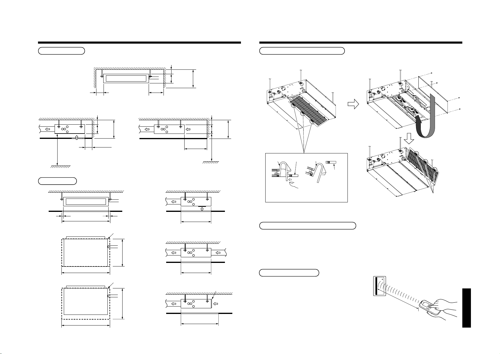
Remove the filter from the main unit while
pushing down on the tabs.
Force
Air filter
Main unit
Remove the cover plate
and then fix it to the
bottom surface.
Main unit
(after remover)
Air filter
Do surely hooking
to the main unit.
SELECTION OF INSTALLATION PLACE
21
Installation space
Reserve space required for maintenance the indoor unit and service work.
Air outlet
100 or more
250
or more
<Under air inlet> <Back air inlet>
5 or more
235
210
or more
Ceiling
Air inlet
2500 or more
Floor surface
50 or more
Ceiling
Service space
Air outlet
Ceiling
50
945
50
Service door (Ceiling opening)
645
5 or more
210
235 or more
Air inlet
300 or more
Floor surface
645
(Unit : mm)
5 or more
210
2500 or more
235
or more
Arranging the to back air inlet type
<Back air inlet>
Notification of filter cleaning term setup
The lighting term setup of the filter sign (Notification of filter cleaning) of the remote controller can be changed
according to the condition of installation.
For setup method, refer to “Change of lighting term of filter sign” and “To secure better effect of heating” in the
Applicable controls of this Manual.
945
Service door (Ceiling opening)
945
745
645
745
Air filter
In case of wireless type
The sensor of indoor unit with wireless remote
controller can receive a signal 8m or less.
Based upon it, determine a place where the remote
controller is operated and the installation place of the
indoor unit.
• To prevent a malfunction, select a place where is not
influenced by a florescent light or direct sunlight.
• Two or more (Up to 6 units) indoor units with
wireless remote controller can be installed in the
same room.
“SPH” series
8m or less
Page 22
4
Anchor bolt
(Blade type
bracket)
(Slide type
bracket)
(Pipe hanging
anchor bolt)
Reinforcing
steel
Hanging bolt
Hanging bolt Support angle
INSTALLATION OF INDOOR UNIT
22
WARNING
Install the air conditioner certainly to sufficiently withstand the weight.
If the strength is insufficient, the unit may fall down resulting in human injury.
Perform a specified installation work to guard against strong wind or earthquake.
An incomplete installation can cause accidents by the units falling and dropping.
REQUIREMENT
Strictly comply with the following rules to prevent damage of the indoor units and human injury.
• Do not put a heavy article on the indoor unit. (Even units are packaged)
• Carry in the indoor unit as it is packaged if possible. If carrying in the indoor unit unpacked by necessity, be
sure to use buffering cloth, etc. to not damage the unit.
• To move the indoor unit, hold the hooking metals (4 positions) only.
Do not apply force to the other parts (refrigerant pipe, drain pan, foamed parts, or resin parts, etc.).
• Carry the package by two or more persons, and do not bundle it with PP band at positions other than
specified.
External view
845
21
57
Ø92
80
Fresh air inlet
(knock-out hole)
168
(inside)
21
21
20
19
4-Ø4
168
80
120
59
803 (inside)
Air filter
805
910
21
210
103
67
511
645
67
Hung-up plate
Refrigerant piping
31
33
163
Drain-up port
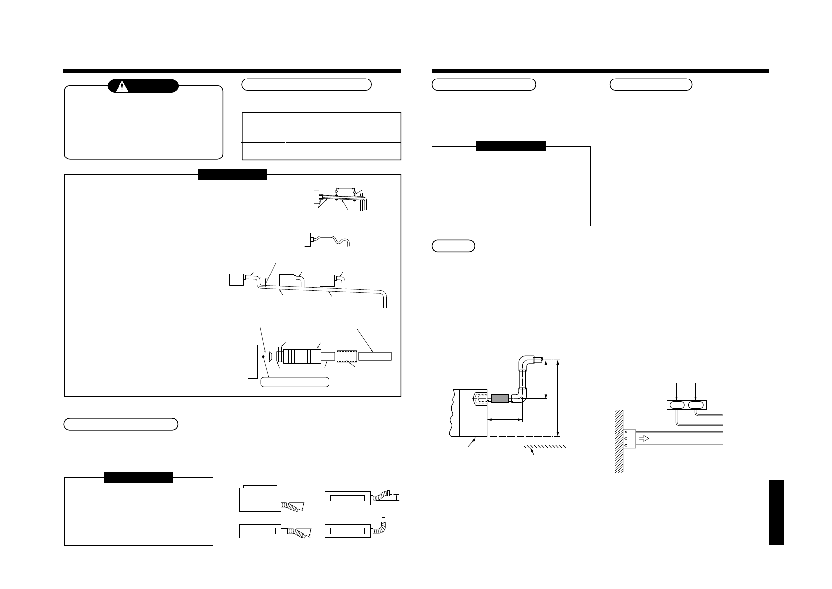
Opening hole on ceiling and placing of hanging bolt
• Considering the indoor unit and the hanged-up piping/wiring work, determine the installation position and direction.
• After installation position of the indoor unit has been determined, open a hole on the wiring and place the hanging bolt.
• For opening size of the ceiling and the hanging bolt pitch, see the external view.
• When the ceiling has already boarded, draw the drain pipe, refrigerant pipe, inter-unit wire between indoor and
outdoor units, central control system wire, and remote controller wire up to the position where pipes and wires are
connected before hanged-up the indoor unit.
The hanging bolts and nuts will be procured locally.
Hanging bolt
Nut
M10 or W3/8
M10 or W3/8
4 pieces
12 pieces
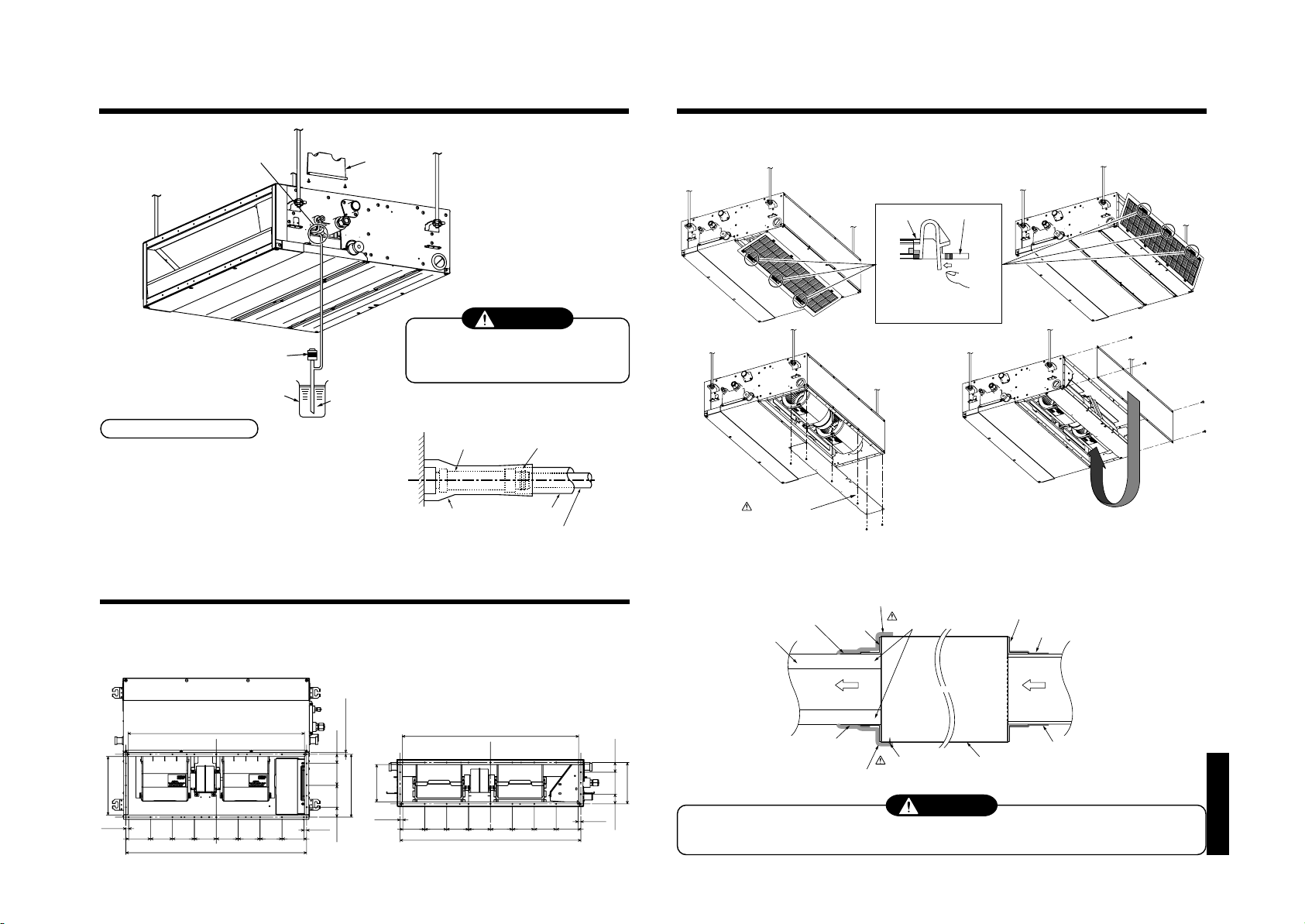
Installation of hanging bolt
Use M10 hanging bolts (4 pcs, to be local procure).
Matching to the existing structure, set pitch according to size in the unit external view as shown below.
New concrete slab
Install the bolts with insert brackets or anchor
bolts.
Installation of indoor unit
• Attach the nuts (M10 or W3/8: Procured locally) and
the attached washers (Ø34) to the hanging bolt.
• Put washers at up and down of T-groove of the
hanging bracket of the indoor unit to hang down the
indoor unit.
• Using a level vial, check that four sides are
372
502
422
359
40
horizontal. (Horizontal degree: Within 5mm)
Steel flame structure
Use existing angles or install new
support angles.
Hanging bolt
(W3/8 or M10)
Nut
(W3/8 or M10)
Nut
(W3/8 or M10)
(1)Required those other than M10 flat washer at site.
(2)To prevent falling-off of bolt (safety), be sure to set it
just under the hanging bracket as shown in the figure.
Existing concrete slab
Use a hole-in anchors, hole-in
plugs, or a hole-in bolts.
(1)
M10 flat washer
(Accessory)
(2)
M10 flat washer
(Accessory)
“SPH” series
Page 23
5
Rising up
687mm or less
Rising up 850mm or less
300mm
or less
Indoor unit
Underneath of ceiling
DRAIN PIPING WORK
23
CAUTION
• Following the Installation Manual, perform
the drain piping work so that water is
properly drained, and apply a heat
insulation so as not to cause a dew.
Inappropriate piping work may result in
water leakage in the room and wet of
furniture.
Pipe material/Insulator and size
The following materials for piping work and insulating
process are procured locally.
Hard vinyl chloride pipe socket for VP25
Pipe material
Insulator
Hard vinyl chloride pipe VP25
(Nominal outer diameter Ø32mm)
Foamed polyethylene foam, thickness:
10mm or more
REQUIREMENT
• Be sure to perform heat insulation of the drain pipes of the indoor unit.
• Never forget to perform heat insulation of the connecting part with the
indoor unit. An incomplete heat insulation causes dewing.
• Set the drain pipe with downward slope (1/100 or more), and do not
make swelling or trap on the piping. It may cause an abnormal sound.
• For length of the traversing drain pipe, restrict to 20m or less.
In case of a long pipe, provide support brackets with interval of
1.5 to 2m in order to prevent waving.
• Set the collective piping as shown in the right figure.
• Do not mount an air purge pipe,
otherwise drain water spouts
out resulted in water leak.
(Collective pipes)
• The hard vinyl-chloride pipe cannot be directly
connected to the drain pipe connecting port of
As long as possible (100mm or more)
VP25
VP30 or more
the indoor unit. For connection with the drain
pipe connecting port, be sure to fix the attached
flexible hose.
• Adhesive agent cannot be used for the pipe
connecting port (hard socket) of the indoor unit.
Drain pipe connecting port
(Hard socket)
Align the attached hose band to the
end of hose, set the tightening
position upward, and then tighten it.
Be sure to use the attached hose band for
fixing, otherwise damage or water leakage of
the drain pipe connecting port is caused.
Soft socket Hard socket
Indoor unit
Adhesive agent prohibited
VP25
1.5m to 2m
Heat
insulator
Arched
shape
Tra p
Downward slope
1/100 or more
Support
bracket
1/100 or more
downward
NO
GOOD
VP25
Ø25 vinyl chloride pipe
(Local supply)
Socket for VP25
(Local supply)
Connection of flexible hose
• Insert the soft socket of the attached flexible hose into the connecting port of the drain pipe until it strikes against
the end.
• Align the attached hose band to the end of the pipe connecting port, and then tighten it surely.
Connection of drain pipe
• Connect the hard socket (local supply) to the hard
socket side of the attached flexible hose which has
been installed.
• Connect the drain pipes (local supply) successively
to the connected the hard socket.
REQUIREMENT
• Using adhesive agent for vinyl chloride, connect
the hard vinyl chloride pipes certainly so that
water does not leak.
• It requires several times to dry and harden the
adhesive agent.
(Refer to Guide Manual of the adhesive agent.)
In this time, be sure not to apply force to the
connecting section with the drain pipes.
Drain up
When a downward grading cannot be secured on the
drain pipe, a drain-up work is possible.
• Set the height of the drain pipe within 850mm from
the bottom surface of the indoor unit.
• Draw out the drain pipe within 300mm from the end
of the drain pipe connecting port of the indoor unit,
and then raise it vertically.
• After the drain pipe has been raised, set a grading
so that it is immediately bent downward.
Check the draining
After drain piping work, check that water drain is
properly performed and water does not leak from the
connecting part of the pipes. In this time, check also
there is no abnormal sound of the motor of the drain
pump. Be sure to check draining when installed in the
heating period.
When the electric work has finished:
• Pour water as shown in the following figure, check
water is drained from the drain pipe connecting port
in COOL mode, and then check there is no water
leak from the drain pipes.
When the electric work has not finished:
• Pull out the float switch connector (3P: Red) from
P.C. board connector (CN34: Red) of the electric
parts box. (In this time, be sure to check the power
is turned off.)
• Connect the single-phase 220-240V 50Hz (or 220V
60Hz) power to the terminal blocks R (L) and S (N).
(Never apply 220-240V to (A), (B), (U1),and (U2),
otherwise a trouble of P.C. board occurs.)
• Pour water referring to the figure.
(Amount: 1500cc to 2000cc)
• When the power is turned on, the drain pump motor
drives automatically.
Check water is drained from the drain pipe
connecting port, and then check there is no water
leak from the drain pipes.
• After check of draining and water leak, turn off the
power supply, attach the float switch connector to
the original position (CN34) of P.C. board, and then
set the electric parts box as before.
220–240V ~, 50Hz
220V
~
, 60Hz
R(L) S(N)
CN34
(RED)
Black
Pull out connector CN34 (Red) from P.C. board.
Black
White
Red
REQUIREMENT
• Be sure to fix the soft socket with the
attached hose band and set the
tightening position at upper side.
• Use the attached flexible hose by
bending it with 45° or less so that no
breakage or clogging occurs.
OK NO GOOD
Top view
Air outlet
max
45˚
max
45˚
Side view
Air outlet
Side viewSide view
Air outlet
“SPH” series
Riser (Trap)
90˚ Bend
Page 24
24
Remove the cover plate and
then fix it to the bottom surface.
Remove the filter from the
main unit while pushing
down on the tabs.
Force
Air filter
Main unit
CAUTION
Take out this cover plate.
Air inlet sideAir outlet side
Indoor unit
Aluminum tape (Local supply)
Aluminum tape (Local supply)
Duct:Insulation material
(Local supply)
Aluminum tape
(Local supply)
Under surface
Cover a screw
Flange
Connect a duct to the
inside of the flange
Heat insulator with sticking material (100mm-width Local supply)
Heat insulator with sticking material (100mm-width Local supply)
Aluminum tape (Local supply)
Flange (Local supply)
5
DRAIN PIPING WORK
Insert the edge of hose into the
drain pan and bend it downward.
Pump
Vessel
Heat insulating process
• After drain check, using the attached heat insulator
for drain connecting section, wrap the flexible hose
without clearance from the end of the drain pipe
connecting port of the indoor unit.
• Covering the attached heat insulator for drain
connecting section, wrap the drain pipe with heat
insulator (local supply) without clearance.
Cover plate
Water
(1500cc~2000cc)
Attached heat insulator
CAUTION
Pour water slowly.
If it is poured urgently, water is spread inside
of the indoor unit resulted in a trouble.
Flexible hose
Hose band
Heat insulator to be
procured locally
Hard vinyl chloride pipe
Be sure to mount an air filter to the air inlet side; otherwise decrease of capacity and etc. may be caused.
<Under air inlet> <Back air inlet>
6
AIR DUCTING
6-1. Arrangement
Referring to the following dimensions, manufacture duct at the local site.
<Under air inlet> <Back air inlet>
266
12.5
100100100
805
100100
825
100
100 100
8.2 or less
12.5
170
286.8
12.5
45.3 41.5100100
6-2. Connecting method of the duct
805
“SPH” series
188
12.5
100 100 100
100
100100
100100
825
44.3 100 44.3
Incomplete heat insulation of the supply air flange and sealing may occur dewing resulted in falling of water
drop.
CAUTION
Page 25
7
B
Work using double spanner
REFRIGERANT PIPING
25
WARNING
• If refrigerant gas has leaked during the installation work, ventilate the room immediately.
• If the leaked refrigerant gas comes in contact with fire, noxious gas may generate.
• After the installation work, confirm that refrigerant gas does not leak.
• If refrigerant gas leaks into the room and flows near a fire source, such as a cooking range, noxious gas may
generate.
REQUIREMENT
When the refrigerant pipe is long, set the support brackets to fix the pipe with 2.5 to 3m intervals. If the pipe is
not fixed, abnormal sound may generate.
Be sure to use the flare nuts attached to the indoor unit or those fro R410A.
Permissible pipe length and permissible height difference
They are different according to the used outdoor unit. For details, refer to the Installation Manual attached to the
outdoor unit.
Piping material and dimensions
Piping material
Model MMD-
Pipe size (mm)
• Use a clean and new pipe, and check that impurity such as dust, oil, moisture, etc. does not adhere in the pipe.
Gas side
Liquid side
Pipe forming/End positioning
Flaring
1. Cut the pipe with a pipe cutter.
NO GOODOK
90˚
2. Insert a flare nut into the pipe, and flare the pipe.
As the flaring sizes of R410A differ from those of
refrigerant R22, the flare tools newly manufactured
for R410A are recommended.
However, the conventional tools can be used by
adjusting projection margin of the copper pipe.
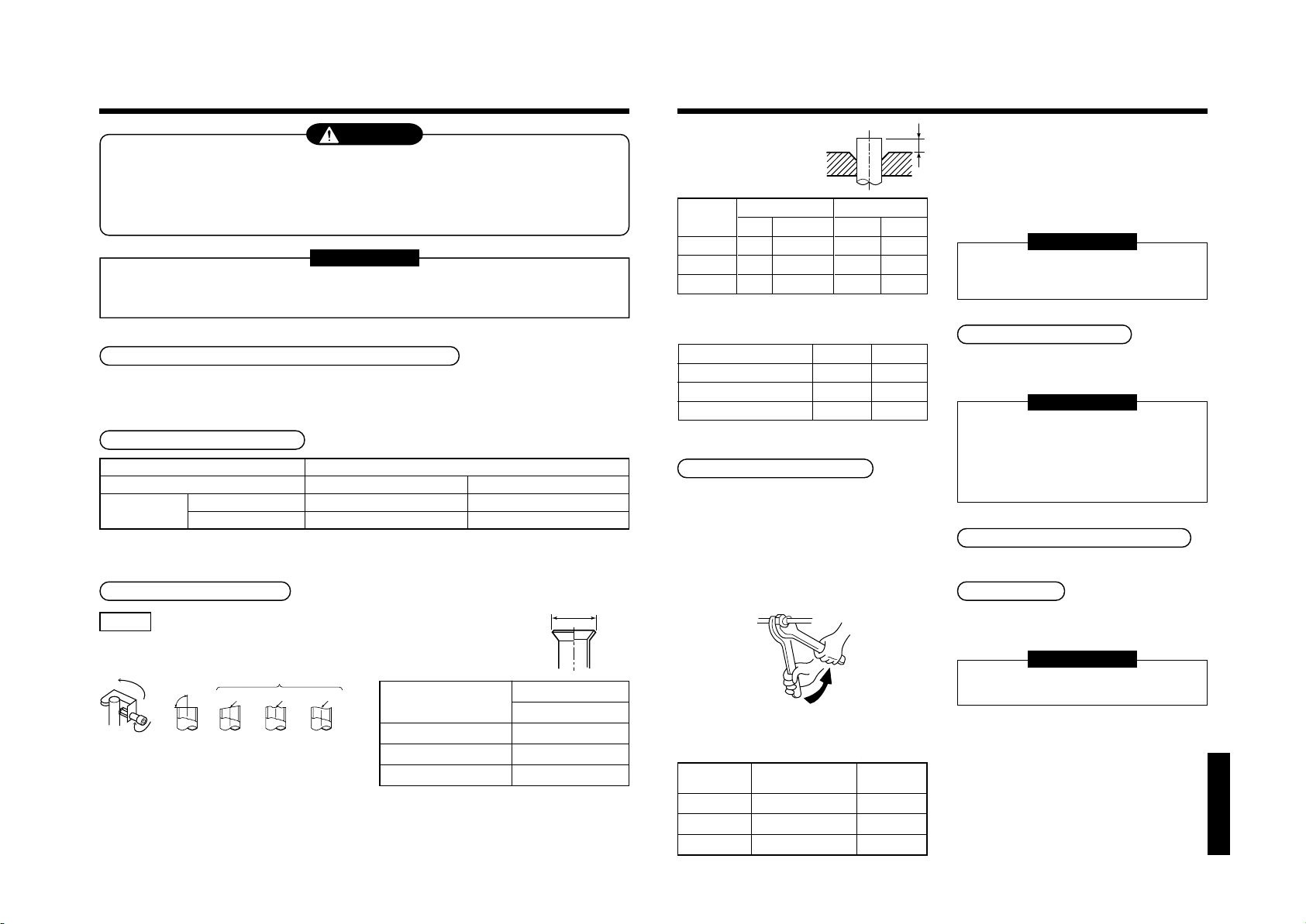
Obliquity Roughness Warp
Phosphor deoxidization joint-less pipe for air conditioner
AP007 to AP012 AP015 to AP018
Ø9.5 Ø12.7
Ø6.4 Ø6.4
• Flaring diam. meter size :
A
A (Unit : mm)
+0
A
Outer diam. of
copper pipe
6.4
9.5
12.7
In case of flaring for R410A with the conventional
*
flare tool, pull it out approx. 0.5 mm more than that
for R22 to adjust to the specified flare size.
The copper pipe gauge is useful for adjusting
projection margin size.
- 0.4
R410A
9.1
13.2
16.6
• Projection margin in flaring :
B (Unit : mm)
Rigid (Clutch type)
Outer diam. of
copper pipe
6.4
9.5
12.7
Imperial (Wing nut type)
Outer diam. of copper pipe
R410A tool used
R410A R22
0 to 0.5 (Same as left)
0 to 0.5 (Same as left)
0 to 0.5 (Same as left)
6.4
9.5
12.7
Conventional tool used
R410A R22
1.0 to 1.5 0.5 to 1.0
1.0 to 1.5 0.5 to 1.0
1.0 to 1.5 0.5 to 1.0
R410A R22
1.5 to 2.0 1.0 to 1.5
1.5 to 2.0 1.0 to 1.5
2.0 to 2.5 1.5 to 2.0
Connection of refrigerant pipe
Connect all the refrigerant pipes with flare connecting
work.
• Since the atmospheric pressure only is sealed
as the sealing gas, it is not abnormal that
“Pushu…” sound is not heard when the flare
nut is removed.
• Be sure to use a double spanner for pipe
connecting work of the indoor unit.
• Refer to the following table for tightening torque.
Connecting pipe
outer dia. (mm)
Ø6.4
Ø9.5
Ø12.7
Tightening torque
(N•m)
14 to18 (1.4 to 1.8 kgf•m)
33 to 42 (3.3 to 4.2 kgf•m)
50 to 62 (5.0 to 6.2 kgf•m)
Re-tightening
torque (N•m)
18 (1.8 kgf•m)
42 (4.2 kgf•m)
62 (6.2 kgf•m)
• Tightening torque of flare pipe connections
Pressure of R410A is higher than that of R22 by
approx. 1.6 times. Therefore, using a torque wrench,
tighten the flare pipe connecting sections which
connect the indoor and outdoor units of the specified
tightening torque. Incorrect connections may cause
not only a gas leak, but also a trouble of the
refrigerating cycle.
REQUIREMENT
If an excessive torque is applied, the nut
may crack depending on the installation
conditions.
Airtight test/Air purge, etc.
For airtight test, air purge, addition of refrigerant, and
gas leak check, follow the Installation Manual attached
to the outdoor unit.
REQUIREMENT
Be sure to use the tool such as charge hose
exclusive to R410A.
Do not turn on the power until the airtight test and
the vacuuming have finished. (If turning on the
power, the incorporated PMV is closed fully and
the period until the vacuuming finishes elongates.
Open fully valves of the outdoor unit
Gas leak check
Check with a leak detector or soap water whether gas
leaks or not, from the pipe connecting section or cap
of the valve.
REQUIREMENT
Use a leak detector manufactured exclusively for
HFC refrigerant (R410A, R134a, etc.).
“SPH” series
Page 26
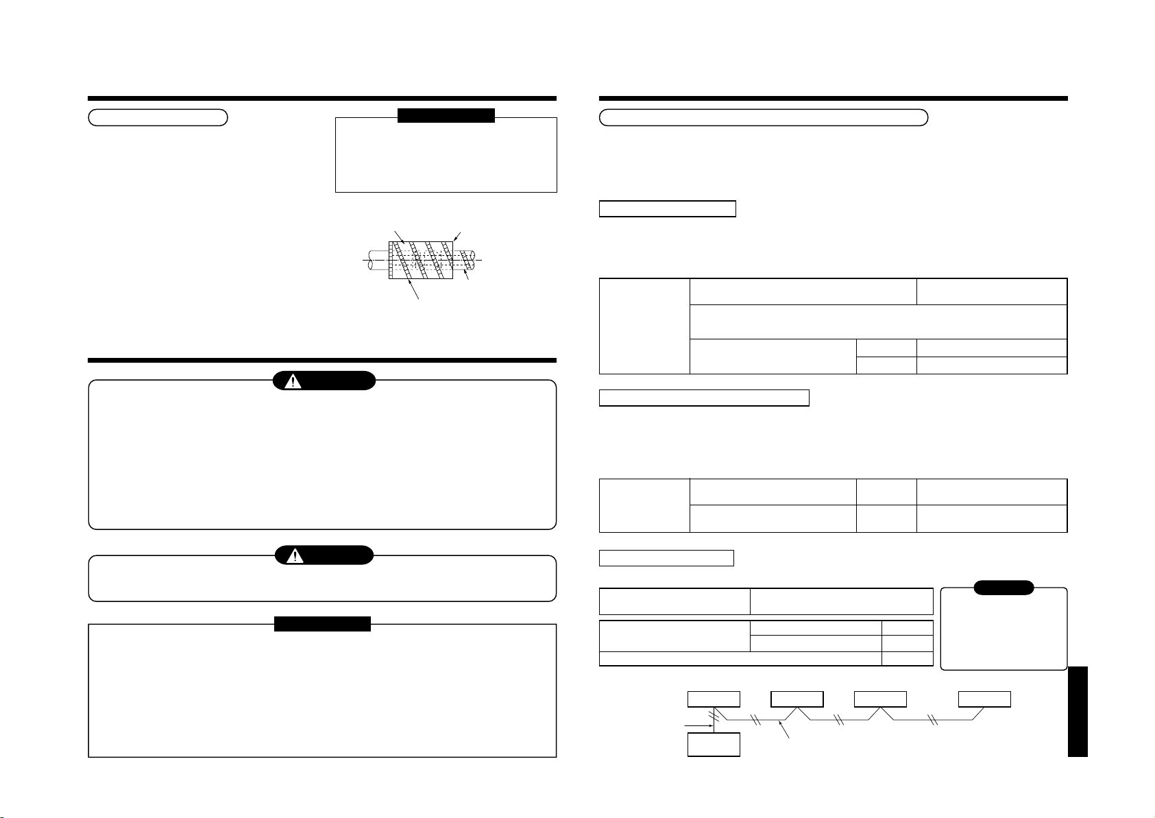
7
Remote controller inter-unit wiring
Indoor unit
Remote
controller
Indoor unit
L1 L2 Ln
(Max. 8 units)
Indoor unit Indoor unit
Remote
controller
wiring
REFRIGERANT PIPING
26
Heat insulating process
Perform heat insulating for pipes at liquid side and gas
side separately.
In cooling time, temperature at both liquid and gas
sides becomes lower.
Therefore, perform heat insulating process sufficiently
to avoid dewing.
• For heat insulator of pipe at gas side, be sure to use
one with
heat-resisting temp.120°C or more.
• Using the attached heat insulating pipe, perform heat
insulating process
securely for pipe connecting part of the indoor units
without clearance.
8
ELECTRIC WORK
Apply the heat insulation to the pipe connecting
section of the indoor unit securely up to the root
without exposure of the pipe.
(The pipe exposed to the outside causes water
leak.)
Using tape,
fix the heat insulator.
REQUIREMENT
Set notching upward.
Pipe side
Attached heat insulating pipe
(Required at the site)
WARNING
1. Using the specified wires, ensure to connect the wires, and fix wires securely so that the
external strength of the wires do not transmit to the connecting part of the terminals.
Incomplete connection or fixation may cause a fire, etc.
2. Be sure to connect earth wire. (Grounding work)
Do not connect the earth wire to gas pipe, city water pipe, lightning rod, or the earth wire of telephone.
Incomplete grounding causes an electric shock.
3. For electric work, strictly follow to the Local Regulation in each country and the Installation
Manual, and use an exclusive circuit.
Capacity shortage of power circuit or incomplete installation may cause an electric shock or a fire.
Power supply cord and communication wires specifications
Power supply cord and communication wires are procured locally.
For the power supply specifications, follow to the table below. If capacity is little, it is dangerous because overheat or
seizure may be caused.
For specifications of the power capacity of the outdoor unit and the power supply wires, refer to the Installation
Manual attached to the outdoor unit.
Indoor unit power supply
• For the power supply of the indoor unit, prepare the exclusive power supply separated from that of the outdoor unit.
• Arrange the power supply, earth leakage breaker, and main switch of the indoor unit connected to the same
outdoor unit so that they are commonly used.
• Power supply cord specification : Cable 3-core 2.5mm², in conformity with Design 60245 IEC 57.
~ 50Hz
220–240V
220V
~ 60Hz
Twist wire : 2.0 mm²
Twist wire : 3.5 mm²
Power supply
Power supply
Power supply switch/Earth leakage breaker or power supply wiring/fuse rating for
indoor units should be selected by the accummulated total current values of the indoor units.
Power supply wiring
Below 20m
Below 50m
Control wiring, Central controller wiring
• 2-core with polarity wires are used for the Control wiring between indoor unit and outdoor unit and Central
controller wiring.
• To prevent noise trouble, use 2-core shield wire.
• The length of the communication line means the total length of the inter-unit wire length between indoor and
outdoor units added with the central control system wire length.
Communication line
Control wiring between indoor unit and
outdoor unit (2-core shield wire)
Central control line wiring
(2-core shield wire)
Wire size
Wire size
(Up to 1000m) Twist wire : 1.25 mm²
(Up to 2000m) Twist wire : 2.00 mm²
(Up to 1000m) Twist wire : 1.25 mm²
(Up to 2000m) Twist wire : 2.00 mm²
CAUTION
Be sure to install an earth leakage breaker.
If an earth leakage breaker is not installed, an electric shock may be caused.
REQUIREMENT
• For power supply wiring, strictly conform to the Local Regulation in each country.
• For wiring of power supply of the outdoor units, follow to the Installation Manual of each outdoor unit.
• Never connect 220–240V power to the terminal blocks (A, B, U1, U2, X, Y, etc.) for control wiring.
(Otherwise, the system will be failed.)
• Perform the electric wiring so that it does not come to contact with the high-temperature part of the pipe.
The coating may melt resulted in an accident.
• After connecting wires to the terminal blocks, provide a trap and fix wires with the wire clamp.
• Store the refrigerant piping line and control wiring line in the same line.
• Do not turn on the power of the indoor unit until vacuuming of the refrigerant pipes completes.
Remote controller wiring
• 2-core with non-polarity wire is used for wiring of the remote controller wiring and group remote controllers wiring.
Remote controller wiring, remote
controller inter-unit wiring
Total wire length of remote controller
wiring and remote controller inter-unit
wiring = L + L1 + L2 + … Ln
Total wire length of remote controller inter-unit wiring = L1 + L2 + … Ln
Twist wire: 0.5mm
In case of wired type only
In case of wireless type included
2
to 2.0mm2 × 2
Up to 500m
Up to 400m
Up to 200m
CAUTION
The remote controller wire
(Communication line) and
AC220–240V wires cannot be
parallel to contact each other and
cannot be stored in the same
conduits. If doing so, a trouble
may be caused on the control
system due to noise, etc.
“SPH” series
Page 27
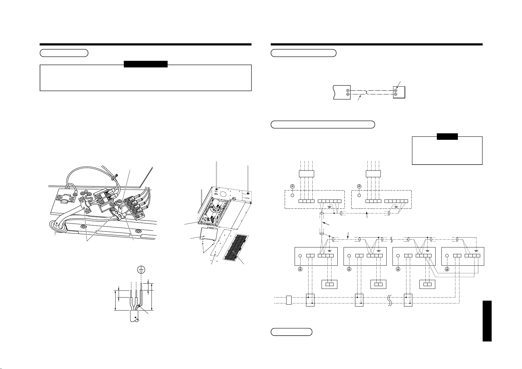
8
Terminal block for
remote controller
wiring of indoor unit
A
B
Remote controller wire
(Field supply)
Remote
controller unit
A
B
Terminal block
Indoor power supply
220-240V, ~50Hz
220V~60Hz
Outdoor Power supply
380V-415V ~ 50Hz
380V ~ 60Hz
Earth leakage
breaker
Header outdoor unit
Indoor unit
Remote controller
Pull box
Earth leakage breaker
power switch
Pull box Pull box
Header outdoor unit
Earth leakage
breaker
Control wiring between indoor and outdoor units
Earth
Earth
terminal
U1 U2
U1 U2 U3 U4L1 L2 L3 N U5 U6
L N A B
A B
Control wiring between outdoor units
Outdoor Power supply
380V-415V ~ 50Hz
380V ~ 60Hz
Earth
terminal
U1 U2 U3 U4L1 L2 L3 N U5 U6
Control wiring between indoor units
Indoor unit
Remote controller
Earth
U1 U2L N A B
A B
Indoor unit
Remote controller
Earth
U1 U2L N A B
A B
Indoor unit
Earth
U1 U2L N A B
ELECTRIC WORK
27
Cable connection
REQUIREMENT
• Be sure to pass the wire through the wire connection port of the indoor unit.
• Keep a margin (Approx. 100mm) on a wire to hang down the electric parts box at servicing, etc.
• The low-voltage circuit is provided for the remote controller.
• Before remove the electric parts cover, remove the cover plate and air filter.
• Remove the cover of the electric parts box by taking off the mounting screws (2 positions) and pushing the
hooking section. (The cover of the electric parts box remains hanged to the hinge.)
• Tighten the screws of the terminal block, and fix the wires with cord clamp attached to the electric parts box.
(Do not apply tension to the connecting section of the terminal block.)
• Be sure to set a loop for the connecting wire of the storing part of the indoor unit electric parts; otherwise the
electric parts box cannot be drawn out in service time.
• Mount the cover of the electric parts box without pinching wires.
Control wire
R
(L
)
S
(N
)
Electric
Power supply cord
Cable cramp
30
Remote controller wire
R
(L)S(N)
10
10
Earth line
Power supply cord
70
parts box
Electric parts
box cover
Screw
(2 positions)
Cover plate
Air filter
Remote controller wiring
• As the remote controller wire has no polarity, there is no problem if connections to indoor unit terminal blocks A
and B are reversed.
<Wiring diagram>
Wiring between indoor and outdoor units
<Wiring example>
An outdoor unit connected with
control wiring between indoor and
outdoor units wire becomes
automatically the header unit.
NOTE
“SPH” series
Address setup
Set up the addresses according to the Installation Manual attached to the outdoor unit.
Page 28
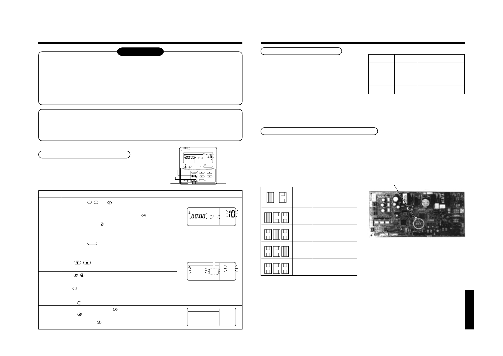
9
T
T
T
T
T
T
t
C
2
C
1
C
0
n
C
2
C
1
C
0
C
2
C
1
C
0
C
2
C
1
C
0
APPLICABLE CONTROLS
28
NOTIFICATION
When using the equipment at the first time, it will take a lot of time that the remote controller accepts an
operation after power was on. However, it is not a trouble.
• Automatic address
• While automatic addressing, the operation cannot be performed on the remote controller.
• For automatic addressing, Max. 10 minutes (generally, approx. 5 minutes) are required.
• When power will be turned on after finish of automatic addressing;
• It will require Max. 10 minutes (generally, approx. 3 minutes) that outdoor unit starts operation after power
was on.
As all have been set to [Standard] at the shipment, change the setup of the indoor unit if necessary.
To change the setup, use the main remote controller (wired remote controller).
* The setup change for wireless remote controller, sub remote controller, or remote controller-less system
(Central control remote controller only is provided.) is impossible. In these cases, prepare and mount a
separate main remote controller.
TIMER SET
CODE No.
UNIT No.
R.C. No.
ON / OFF
FAN
MODE
SWING/FIXTIME
VENT
UNITSET CL
Exchange of applicable control setup
Basic operation procedure for setup exchange
Change the setup while operation of the equipment stops.
(Be sure to stop the operation of a set.)
TEMP.
4
FILTER
TEST
1
RESET
6
Procedure
1
2
3
4
5
6
When pushing
flashes as shown in the figure.
Check that the displayed item code is [10].
• If the item code indicates other than [10], push
the display, and then retry the operation from the first step.
(For some time after
the remote controller cannot be accepted.)
(In a group control, the firstly displayed
indoor unit No. becomes the header unit.)
Every pushing
Select an indoor unit of which setup to be changed.
In this time, the position of the indoor unit of which setup to be changed can
be confirmed because the fan and the flap of the selected indoor unit work.
Using , buttons of set temperature, specify the item
code [
Using , buttons of timer time, select set data [
Push
• To change the setup of an indoor unit other than the selected one, start operation from Procedure
• To change the setup of another setup in the selected indoor unit, start operation from Procedure
Pushing
When the setup finished, push
Pushing
normal stop status.
(For some time after
remote controller cannot be accepted.)
SET, CL
].
**
SET
button. In this time, if the display changes from flashing to lighting, the setup completes.
CL
button clears the set up contents which have been already set. In this case, retry from Procedure 2.
TES
button deletes the display and returns the status to
TES
, and
buttons simultaneously for 4 seconds or more, after a while, the display part
TES
button has been pushed, the operation of
UNIT
button, the indoor unit No. in the group control is displayed successively.
TES
button. (The setup is determined.)
TES
button has been pushed, the operation of the
Description
TES
button to erase
].
****
SETTING
UNIT No.
R.C. No.
(* The display changes according
to the indoor unit model.)
UNIT No.
∗∗
∗∗∗∗∗
∗
R.C. No.
∗
Setup of external static pressure
Be sure to set up a tap change based upon the
resistance (external static pressure) of the duct to be
connected.
To set up a tap change, follow to the basic operation
procedure (
• Specify [5d] to the item code in procedure
• For the setup data of procedure
1
→ 2 → 3 → 4 → 5 → 6 ).
4
3
.
, select a setup
<Change on wired remote controller>
Setup data
0000
0001
0003
0006
External static pressure
10 Pa Standard (At shipment)
20 Pa High static pressure 1
35 Pa High static pressure 2
50 Pa High static pressure 3
data of the external static pressure to be set up from
the following table.
In case of remote controller-less (Group control)
For setup to the high ceiling, there is selecting method by exchanging the short plugs on the indoor microcomputer
P.C. board as shown in the following table other than selecting method by standard wired remote controller (sold
separately). Utilize this method for remote controller-less (Group control) case.
∗ However, when the setup to high ceiling has been once exchanged, it is required for returning it to 0000 to change
the short plug to the standard (at shipment) position and rewrite data to the setup data 0000 from the wired remote
controller sold separately though setup to 0001, 0003 or 0006 are freely available.
3
2
5
CODE No.
CODE No.
∗∗
2
.
3
.
• Select by exchange of short plugs on the indoor
P.C. board.
Short plug position
Set data External static pressure
Shor
Ope
N11
N11
N11
N11
N11
N11
N11
N11
N11
N11
N11
N11
0000
0001
0003
0006
10 Pa (At shipment)
20 Pa
35 Pa
50Pa
• Short plug position
(CN112, CN111, CN110 from the left)
“SPH” series
Page 29
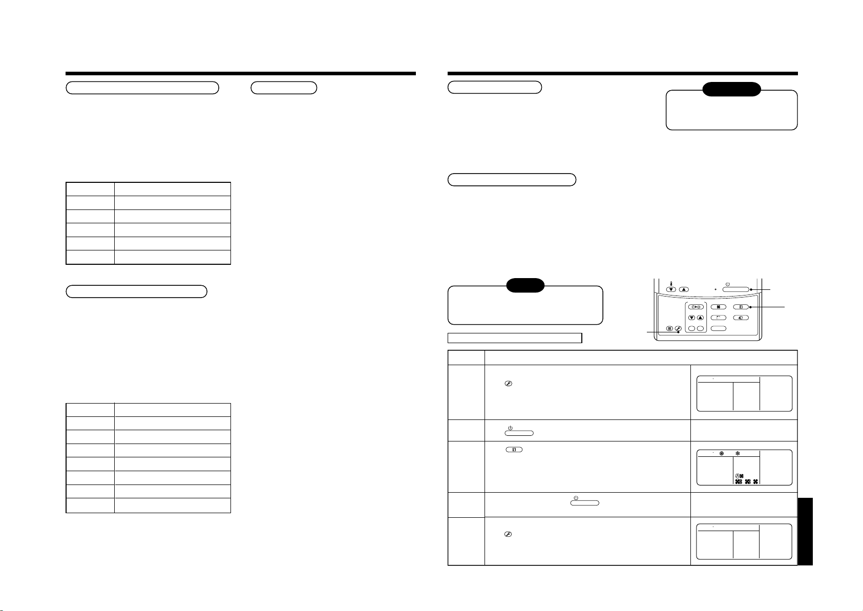
9
T
T
APPLICABLE CONTROLS
10
TEST RUN
29
Change of lighting term of filter sign
According to the installation condition, the lighting term
of the filter sign (Notification of filter cleaning) can be
changed.
Follow to the basic operation procedure
1
→ 2 → 3 → 4 → 5 → 6 ).
(
• For the item code in Procedure
• For the [Set data] in Procedure
data of filter sign lighting terme from the following
table.
Setup data
0000
0001
0002
0003
0004
150H
2500H (At shipment from factory)
5000H
10000H
3
, specify [01].
4
, select the setup
Filter sign lighting term
None
To secure better effect of heating
When it is difficult to obtain satisfactory heating due to
installation place of the indoor unit or structure of the
room, the detection temperature of heating can be
raised. Also use a circulator, etc. to circulate heat air
near the ceiling.
Follow to the basic operation procedure
1
→ 2 → 3 → 4 → 5 → 6 ).
(
• For the item code in Procedure
• For the set data in Procedure
data of shift value of detection temperature to be set
up from the table below.
Setup data
0000
0001
0002
0003
0004
0005
0006
Detection temp shift value
+1°C
+2°C (At shipment from factory)
+3°C
+4°C
+5°C
+6°C
3
, specify [06].
4
, select the setup
No shift
Group control
In a group control, a remote controller can control up
to maximum 8 units.
• For cabling procedure and cables of the individual
line (Identical refrigerant line) system, refer to
“Electric work” in this Manual.
• Cabling between indoor units in a group is performed
in the following procedure.
Connect the indoor units by connecting the remote
controller inter-unit cables from the remote controller
terminal blocks (A, B) of the indoor unit connected
with a remote controller to the remote controller
terminal blocks (A, B) of the other indoor unit.
(No polarity)
• For address setup, refer to the Installation Manual
attached to the outdoor unit.
Before test operation
• Before turning on the power supply, carry out the following items.
1) Using 500V-megger, check there is 1MΩ or more between the
terminal block of the power supply and the earth. If 1MΩ or less
is detected, do not run the unit.
2) Check that all the valves of the outdoor unit are fully opened.
• Never push the electromagnetic contactor to carry out a forced test operation.
(It is very dangerous because a protective device does not work.)
To protect the compressor at
starting time, keep power-ON
condition before 12 hours or more.
WARNING
How to execute test operation
• To carry out a fan operation in a single indoor unit, turn off the power once, short CN72 on P.C. board, and then
turn on the power again. (Start the unit in FAN mode.) In this case, do not forget to clear short-circuit of CN72 after
test operation.
• Using the remote controller, check the operation in the usual operation. For the operation procedure, refer to the
attached Owner’s Manual.
A forced test operation can be executed in the following procedure under condition of thermo-OFF of room
temperature.
In order to prevent a serial operation, the forced test operation is released after 60 minutes and returns to the
usual operation.
NOTE
Do not use a forced operation in cases other
than test operation because it applies an
excessive load to the air conditioner.
In case of wired remote controller
Procedure
TES
Keep
button pushed for 4 seconds or more.
[TEST] is displayed on the display part and the selection of mode in
1
the test mode is permitted.
ON / OFF
Push
2
Using
• Do not run the air conditioner in a mode other than [COOL] or [HEAT].
• The temperature controlling function does not work during test
3
4
operation.
• The detection of error is performed as usual.
After the test operation, push
(Display part is same as procedure
button.
MODE
button, select the operation mode, [COOL] or [HEAT].
1, 5
Description
ON / OFF
button to stop the operation.
1
)
FILTER
RESET
TEMP.
TIMER SET
TEST
ON / OFF
2, 4
FAN
MODE
SWING/FIXTIME
VENT
UNITSET CL
TEST
3
“SPH” series
TES
Push
button to cancel (release from) the test operation mode.
([TEST] disappears on the display part and the status returns to a
5
normal stop status.)
Page 30
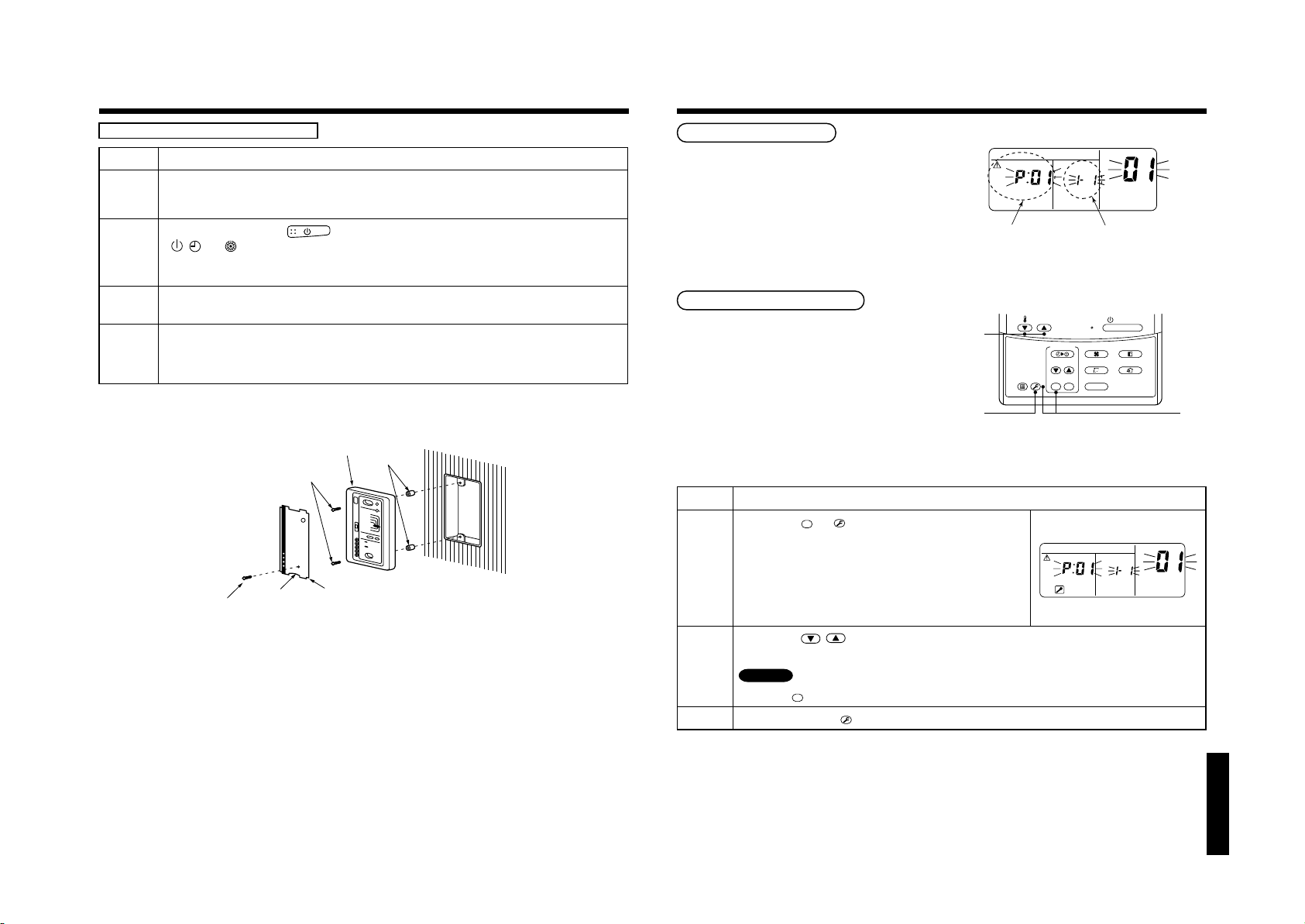
10
T
T
3
2
1
ON / OFF
FAN
TEMP.
SWING/FIXTIME
MODE
VENT
UNITSET CL
FILTER
RESET
TEST
TIMER SET
TEST RUN
11
TROUBLESHOOTING
30
In case of wireless remote controller
Procedure
Remove a small screw which fixes the nameplate of the receiver unit.
Remove the nameplate of the sensor section by inserting a minus screwdriver, etc into the notch at the bottom
1
of the plate, and set the Dip switch to [TEST RUN ON].
Execute a test operation with button on the wireless remote controller.
•
2
3
4
, , and LED flash during test operation.
• Under status of [TEST RUN ON], the temperature adjustment from the wireless remote controller is invalid.
Do not use this method in the operation other than test operation because the equipment is damaged.
Use either COOL or HEAT operation mode for a test operation.
* The outdoor unit does not operate approx. 3 minutes after power-ON and operation stop.
After the test operation finished, stop the air conditioner from the wireless remote controller, and return Dip
switch of the receiver section as before.
(A 60-minutes timer clearing function is attached to the receiver section in order to prevent a continuous test
operation.)
M4 × 25 screw
(2 pieces)
Small screw
Notch
Receiver unit
Nameplate
Description
Spacer
Confirmation and check
When a trouble occurred in the air conditioner, the
check code and the indoor unit No. appear on the
display part of the remote controller.
The check code is only displayed during the operation.
If the display disappears, operate the air conditioner
according to the following “Confirmation of error
history” for confirmation.
Confirmation of error history
When a trouble occurred on the air conditioner, the
error history can be confirmed with the following
procedure.
(The error history is stored in memory up to 4 errors.)
This history can be confirmed from either operating
status or stop status.
Procedure
TES
When pushing
more, the right display appears.
If [Service Check] is displayed, the mode enters in the error history
mode.
1
• [01: Order of error history] is displayed in CODE No. window.
• [Check Code] is displayed in CHECK window.
• [Indoor unit address in which an error occurred] is displayed in
UNIT No.
Every pushing , buttons, the error history stored in the memory is displayed in order.
The numbers in CODE No. indicates CODE No. [01] (Latest) → [04] (Oldest).
2
CAUTION
Do not push
After confirmation, push
3
SET
and
buttons simultaneously for 4 seconds or
CL
button because all the error history of the indoor unit will be deleted.
TES
button to return to the usual display.
Description
CODE No.
UNIT No.
R.C. No.
Check code Indoor unit No. in which
an error occurred
UNIT No.
R.C. No.
CODE No.
“SPH” series
Page 31

11
TROUBLESHOOTING
31
Check method
On the remote controller (Main remote controller, Central control remote controller) and the interface P.C. board of
the outdoor unit (I/F), a check display LCD (Remote controller) or 7-segment display (on the outdoor interface P.C.
board) to display the operation is provided. Therefore the operation status can be known. Using this self-diagnosis
function, a trouble or position with error of the air conditioner can be found as shown in the table below.
Check code list
The following list shows each check code. Find the check contents from the list according to part to be checked.
• In case of check from indoor remote controller: See “Main remote controller display” in the list.
• In case of check from outdoor unit: See “Outdoor 7-segment display” in the list.
• In case of check from AI-NET central control remote controller: See “AI-NET central control display” in the list.
• In case of check from indoor unit with wireless remote controller: See “Sensor block display of receiving unit” in the list.
AI-NET : Artificial Intelligence.
IPDU : Intelligent Power Drive Unit
¡ : Lighting,
ALT. : Flashing is alternately when there are two flashing LED.
SIM : Simultaneous flashing when there are two flashing LED.
Wireless remote controller
Sensor block display
of receiving unit
Operation
Timer Ready Flash
ll
¤
ll
¤
ll
¤
ll
ll
ll
ll
¤
ll
¤
ll
¤
ll
¤
ll
ll
ll
¤
ll
ll
ll
ll
ll
ll
ll
: Flashing, l : Goes off
¤
Check code name
Communication error between indoor and
remote controller
(Detected at remote controller side)
Remote controller transmission error
Communication error between indoor and
remote controller (Detected at indoor side)
Communication circuit error between indoor/
¤
outdoor (Detected at indoor side)
Decrease of No. of indoor units
¤
Communication circuit error between indoor/
¤
outdoor (Detected at outdoor side)
Duplicated indoor addresses
Duplicated main remote controllers
Communication error between indoor MCU
Automatic address start error
Indoor is nothing during automatic addressing
¤
Capacity over / No. of connected indoor units
¤
Communication error between indoor units
Outdoor header units quantity error
¤
Other line connected during automatic
¤
address
Sending error in communication between
¤
outdoor units
Duplicated follower outdoor addresses
¤
Decrease of No. of connected outdoor units
¤
Follower outdoor unit error
¤
IPDU communication error
¤
Judging device
Remote controller
Remote controller
Indoor
Indoor
I/F
I/F
Indoor / I/F
Remote controller
Indoor
I/F
I/F
I/F
Indoor
I/F
I/F
I/F
I/F
I/F
I/F
I/F
Main
remote
controller
display
Outdoor 7-segment display
E01
——
E02
——
E03
——
E04
——
E06
—
E08
E09
E10
E12
E15
E16
E18
E19
E20
E23
E25
E26
E28
E31
No. of indoor units in which
E06
sensor has been normally
received
E07 —
E08 Duplicated indoor addresses
——
——
01: Indoor/Outdoor
communication
E12
02: Communication between
outdoor units
E15 —
00: Capacity over
E16
~:No. of connected units
01
——
00: Header is nothing
E19
02: Two or more header units
01: Outdoor of other line
connected
E20
02: Indoor of other line
connected
E23 —
E25 —
No. of outdoor units which
E26
received signal normally
E28 Detected outdoor unit number
01: IPDU1 error
02: IPDU2 error
03: IPDU1, 2 error
E31 04:Fan IPDU error
05: IPDU + Fan IPDU error
06: IPDU2 + Fan IPDU error
07: All IPDU error
Check code
Auxiliary code
Terminology
AI-NET central
control display
—
—
97
04
04
—
96
99
CF
42
42
89
97, 99
96
42
15
15
15
d2
CF
Main
remote
controller
display
Outdoor 7-segment display
F01
——
F02
——
F03
——
F04
F04 —
F05
F05 —
F06
F06 —
F07
F07 —
F08
F08 —
F10
——
F12
F12 —
F13
F15
F16
F23
F24
F29
F31
H01
H02
H03
H04
H06
H07
H08
H14
H16
L03
L04
L05
L06
L07
L08
L09
L10
L20
L28
L29
L30
—
01: Comp. 1 side
F13
02: Comp. 2 side
F15 —
F16 —
F23 —
F24 —
——
F31 —
01: Comp. 1 side
H01
02: Comp. 2 side
01: Comp. 1 side
H02
02: Comp. 2 side
01: Comp. 1 side
H03
02: Comp. 2 side
H04 —
H06 —
H07 —
01: TK1 sensor error
02: TK2 sensor error
H08
03: TK3 sensor error
04: TK4 sensor error
H14 —
01: TK1 oil circuit system error
02: TK2 oil circuit system error
H16
03: TK3 oil circuit system error
04: TK4 oil circuit system error
——
L04 —
——
L06 No. of indoor units with priority
——
L08 —
——
L10 —
L20 —
L28 —
01: IPDU1 error
02: IPDU2 error
03: IPDU3 error
L29 04: Fan IPDU error
05: IPDU1 + Fan IPDU error
06: IPDU2 + Fan IPDU error
07: All IPDU error
L30 Detected indoor address
L31 —
Check code
Auxiliary code
AI-NET central
control display
0F
0d
93
19
A1
18
18
1b
OC
A2
43
18
43
43
43
12
1C
IF
1d
17
44
20
d7
d4
44
d7
96
96
96
96
99
99
46
88
98
46
CF
b6
—
Wireless remote controller
Sensor block display
of receiving unit
Operation
Timer Ready Flash
¤¤
¤¤
¤¤
¤¤
¤¤
¤¤
¤¤
¤¤
¤¤
¤¤
¤¤
¤¤
¤¤
¤¤
¤¤
¤¤
¤¤
l
l
l
l
l
l
l
l
l
¤
¤
¤
¤
¤
¤
¤
¤
¤
¤
¤
¤
l
l
l
¡
¡
¡
¡
¡
l
¡
¡
¡
¡
¡
¡
l
¡
l
¤
l
¤
l
¤
l
¤
l
¤
l
¤
l
¤
l
¤
l
¤
l
¤
¡
¤
l
¤
l
¤
l
¤
l
¤
l
¤
¡
¤
¡
¤
¡
¤
¡
¤
¡
¤
—
Check code name
ALT
Indoor TCJ sensor error
ALT
Indoor TC2 sensor error
ALT
Indoor TC1 sensor error
ALT
TD1 sensor error
ALT
TD2 sensor error
ALT
TE1 sensor error
ALT
TL sensor error
ALT
TO sensor error
ALT
Indoor TA sensor error
ALT
TS1 sensor error
ALT
TH sensor error
ALT
Outdoor temp. sensor miscabling (TE, TL)
ALT
Outdoor pressure sensor miscabling (Pd, Ps)
ALT
Ps sensor error
ALT
Pd sensor error
SIM
Indoor other error
SIM
Indoor EEPROM error
Compressor break down
Magnet switch error
Overcurrent relay operation
Compressor trouble (lock)
Current detect circuit system error
Comp 1 case thermo operation
Low pressure protective operation
Oil level down detective protection
Oil level detective temp sensor error
Comp 2 case thermo operation
Oil level detective circuit error
Magnet switch error
Overcurrent relay operation
SIM
Indoor center unit duplicated
SIM
Outdoor line address duplicated
Duplicated indoor units with priority
SIM
(Displayed in indoor unit with priority)
Duplicated indoor units with priority
SIM
(Displayed in unit other than indoor unit with
priority)
SIM
Group line in individual indoor unit
SIM
Indoor group/Address unset
SIM
Indoor capacity unset
SIM
Outdoor capacity unset
SIM
Duplicated central control addresses
SIM
Over No. of connected outdoor units
SIM
No. of IPDU error
SIM
Indoor outside interlock
Extended I/C error
Judging device
Indoor
Indoor
Indoor
I/F
I/F
I/F
I/F
I/F
Indoor
I/F
IPDU
I/F
I/F
I/F
I/F
Indoor
I/F
IPDU
MG-SW
Overcurrent relay
IPDU
IPDU
I/F
I/F
I/F
I/F
I/F
I/F
MG-SW
Overcurrent relay
Indoor
I/F
I/F
I/F
Indoor
Indoor, I/F
Indoor
I/F
AI-NET, Indoor
I/F
I/F
Indoor
I/F
“SPH” series
Page 32

11
TROUBLESHOOTING
32
Main
remote
controller
display
Outdoor 7-segment display
P01
——
P03
P03 —
P04
P05
P07
P10
P12
P13
P15
P17
P19
P20
P22
P26
P29
P31
—
—
—
01: Comp. 1 side
P04
02: Comp. 2 side
01: Phase-missing detection
P05
02: Phase error
01: Comp. 1 side
P07
02: Comp. 2 side
P10 Detected indoor address
——
P13 —
01: TS condition
P15
02: TD condition
P17 —
P19 Detected outdoor unit number
P20 —
0 : IGBT short
: Fan motor position
1
: Fan motor trouble
3
P22
: TH sensor temp. error
C
: TH sensor error
D
: Vdc output error
E
01: Comp. 1 side
P26
02: Comp. 2 side
01: Comp. 1 side
P29
02: Comp. 2 side
P31 —
——
——
——
Check code
Auxiliary code
detective circuit error
(Heat sink overheat)
AI-NET central
control display
11
1E
21
AF
IC
Ob
11
47
AE
bb
O8
22
1A
14
16
47
b7
97
99
Wireless remote controller
Sensor block display
of receiving unit
Operation
Timer Ready Flash
l
¤
¤
¤
¤
l
l
l
¤
¤
¤
¤
¤
¤
¤
¤
By alarm device ALT
¤¤
l
¤
l
¤
l
¤
l
¤
¤¤
¤¤
¤¤
l
¤
l
¤
l
¤
l
¤
l
¤
l
¤
l
¤
l
¤
—
—
ALT
ALT
ALT
ALT
ALT
ALT
ALT
ALT
ALT
ALT
ALT
ALT
ALT
ALT
ALT
ALT
Check code name
Indoor fan motor error
Discharge temp. TD1 error
High-pressure SW system operation
Phase-missing detection /Phase error
Heat sink overheat error
Indoor overflow error
Indoor fan motor error
Outdoor liquid back detection error
Gas leak detection
Discharge temp. TD2 error
4-way valve inverse error
High-pressure protective operation
Outdoor fan IPDU error
G-TR short protection error
Comp position detective circuit system error
Other indoor unit error
(Group terminal unit error)
Error in indoor group
AI-NET communication system error
Duplicated network adaptors
Judging device
Indoor
I/F
IPDU
I/F
IPDU, I/F
Indoor
Indoor
I/F
I/F
I/F
I/F
I/F
IPDU
IPDU
IPDU
Indoor
AI-NET
AI-NET
AI-NET
New check code
1. Difference between the new check code and the current system
The displaying method of the check code changes in this model and after.
Check code in current system
Used characters
Characteristics of code classification
Block display
<Display on wired remote controller>
] goes on.
• [
• [UNIT No.] + Check code + Operation lamp (Green) flash
<Display on sensor part of wireless>
• Block display of combination of [
<Display on indicater on wiress remote controller
receiver part>
• Unit No. and check code are displayed.
• In a case of error with auxiliary code, check code and
auxiliary code are displayed alternately.
Hexadecimal notation, 2 digits
Few classification of communication/incorrect setup system
Indoor P.C. board, Outdoor P.C. board, Cycle, Communication
] [ ] [ ]
Alphabet + Decimal notation, 2 digits
Many classification of communication/incorrect setup system
Communication/Incorrect setup (4 ways), Indoor protection,
Outdoor protection, Sensor, Compressor protection, etc.
→
New check code
Display
A
Unused
C
Central control system error
E
Communication system error
F
Each sensor error (Failure)
H
Compressor protective system error
J
Unused
L
Setup error, Other errors
P
Protective device operation
Classification
Error detected by TCC-LINK central control device
Central
control
device
indication
Outdoor 7-segment display
C05
——
C06
——
C12
——
P30
Differs according to error contents of unit with occurrence of alarm
——
Check code
Auxiliary code
AI-NET central
control display
Wireless remote controller
Operation
—
—
—
(L20 is displayed.)
Sensor block display
of receiving unit
Timer Ready Flash
Terminology
TCC-LINK : TOSHIBA Carriea Cominication Link.
Check code name
—
—
—
Sending error in TCC-LINK central
control device
Receiving error in TCC-LINK central
control device
Batch alarm of general-purpose
equipment control interface
Group control branching unit error
Duplicated central control addresses
Judging device
TCC-LINK
TCC-LINK
General-purpose equipment
I/F
TCC-LINK
“SPH” series
Page 33

33
12
For maintenance, be sure to turn off the main power switch.
MAINTENANCE
CAUTION
Do not handle the buttons with wet hands; otherwise an electric shock may be caused.
<Daily maintenance>
Cleaning of air filter
1
If is displayed on the remote controller,
contact to service on maintenance professional to
cleaning the air filter.
2
Clogging of the air filter decreases cooling/
heating efficiency.
3
After cleaning, push .
display disappears.
[Air filter cleaning method]
1
Take out the air filter.
• Push the tabs (Forward direction as shown in the figure) of the fir filter, and then pull out it to take out the air
filter.
1,
2
3
FILTER
RESET
TEMP .
TEST
TIMER SET
FAN
SWING/FIXTIME
UNITSET CL
CODE No.
ON / OFF
MODE
VENT
Air filter
Remove the filter from the
main unit while pushing
down on the tabs.
2
Cleaning with water or vacuum cleaner
• If dirt is heavy, clean the air filter by tepid water with neutral detergent or water.
• After cleaning with water, dry the air filter sufficiently in a shade place.
3
Mount the air filter.
• Attach the filter to the main unit while pushing the tabs
(Forward direction as shown in the figure).
4
Push .
• display disappears.
Main unit
Force
NOTE
When connecting a return air duct g to the unit, r cleaning method of the air filter differs according to the
construction of duct end. Please ask the constructor for construction of air duct.
“SPH” series
Page 34

Accessory parts
34
H Accessory parts
Part name
Installation Manual 1 This manual (Be sure to hand over to customers)
Insulating pipe 2 For insulating pipe connecting section
Washer 8 M10 × Ø34 For hanging down the unit
Hose band 1 2 For connecting drain pipe
Flexible hose 1 For adjustment of drain pipe centering
Heat insulator 1 For insulating drain connecting section
Banding band — 2 For drain hose forming
1
PRECAUTIONS FOR SAFETY
• Ensure that all Local, National and International regulations are satisfied.
• Read this “PRECAUTIONS FOR SAFETY” carefully before Installation.
• The precautions described below include the important items regarding safety. Observe them without fail.
• After the installation work, perform a trial operation to check for any problem.
Follow the Owner’s Manual to explain how to use and maintain the unit to the customer.
• Turn off the main power supply switch (or breaker) before the unit maintenance.
• Ask the customer to keep the Installation Manual together with the Owner’s Manual.
SPH model
with drain pump
CAUTION New Refrigerant Air Conditioner Installation
• THIS AIR CONDITIONER ADOPTS THE NEW HFC REFRIGERANT (R410A) WHICH DOES NOT
DESTROY OZONE LAYER.
The characteristics of R410A refrigerant are ; easy to absorb water, oxidizing membrane or oil, and its pressure
is approx. 1.6 times higher than that of refrigerant R22. Accompanied with the new refrigerant, refrigerating oil
has also been changed. Therefore, during installation work, be sure that water, dust, former refrigerant, or
refrigerating oil does not enter the refrigerating cycle.
To prevent charging an incorrect refrigerant and refrigerating oil, the sizes of connecting sections of charging
port of the main unit and installation tools are charged from those for the conventional refrigerant.
Accordingly the exclusive tools are required for the new refrigerant (R410A).
For connecting pipes, use new and clean piping designed for R410A, and please care so that water or dust does
not enter. Moreover, do not use the existing piping because there are problems with pressure-resistance force
and impurity in it.
Q’ty
SH model
without drain pump
Shape Usage
CAUTION To Disconnect the Appliance from Main Power Supply.
This appliance must be connected to the main power supply by means of a switch with a contact separation of
at least 3 mm.
WARNING
• Ask an authorized dealer or qualified installation professional to install/maintain the air
conditioner.
Inappropriate installation may result in water leakage, electric shock or fire.
• Turn off the main power supply switch or breaker before attempting any electrical work.
Make sure all power switches are off. Failure to do so may cause electric shock.
• Connect the connecting wire correctly.
If the connecting wire is connected in a wrong way, electric parts may be damaged.
• When moving the air conditioner for the installation into another place, be very careful not to
enter any gaseous matter other than the specified refrigerant into the refrigeration cycle.
If air or any other gas is mixed in the refrigerant, the gas pressure in the refrigeration cycle becomes
abnormally high and it as a result causes pipe burst and injuries on persons.
• Do not modify this unit by removing any of the safety guards or by by-passing any of the safety
interlock switches.
• Exposure of unit to water or other moisture before installation may cause a short-circuit of
electrical parts.
Do not store it in a wet basement or expose to rain or water.
• After unpacking the unit, examine it carefully if there are possible damage.
• Do not install in a place that might increase the vibration of the unit.
• To avoid personal injury (with sharp edges), be careful when handling parts.
• Perform installation work properly according to the Installation Manual.
Inappropriate installation may result in water leakage, electric shock or fire.
• When the air conditioner is installed in a small room, provide appropriate measures to ensure that
the concentration of refrigerant leakage occur in the room does not exceed the critical level.
• Install the air conditioner securely in a location where the base can sustain the weight
adequately.
• Perform the specified installation work to guard against an earthquake.
If the air conditioner is not installed appropriately, accidents may occur due to the falling unit.
• If refrigerant gas has leaked during the installation work, ventilate the room immediately.
If the leaked refrigerant gas comes in contact with fire, noxious gas may generate.
• After the installation work, confirm that refrigerant gas does not leak.
If refrigerant gas leaks into the room and flows near a fire source, such as a cooking range, noxious gas might
generate.
• Electrical work must be performed by a qualified electrician in accordance with the Installation
Manual. Make sure the air conditioner uses an exclusive power supply.
An insufficient power supply capacity or inappropriate installation may cause fire.
• Use the specified wires for wiring connect the terminals securely fix. To prevent external forces
applied to the terminals from affecting the terminals.
• Conform to the regulations of the local electric company when wiring the power supply.
Inappropriate grounding may cause electric shock.
• Do not install the air conditioner in a location subject to a risk of exposure to a combustible gas.
If a combustible gas leaks, and stays around the unit, a fire may occur.
“SH” series
Page 35

2
INSTALLATION OF NEW REFRIGERANT AIR CONDITIONER
3
SELECTION OF INSTALLATION PLACE
35
This air conditioner adopts the new HFC refrigerant (R410A) which does not deplete the ozone layer.
• R410A refrigerant is apt to be affected by impurity such as water, oxidizing membrane, or oils because the
pressure of R410A refrigerant is higher than that of the former refrigerant by approx. 1.6 times. Accompanied with
adoption of the new refrigerant, refrigerating oil has been also changed. Therefore pay attention so that water,
dust, former refrigerant, or refrigerating oil does not enter into the refrigerating cycle of the new refrigerant air
conditioner during installation work.
• To prevent from mixing of refrigerant or refrigerating oil, the size of charge port of the main unit or connecting
section of installation tool differs from that of the air conditioner for the former refrigerant. Accordingly the
exclusive tools are required for the new refrigerant (R410A) as shown below.
• For connecting pipes, use the new and clean piping materials so that water or dust does not enter.
Required tools and cautions on handling
It is necessary to prepare the tools and parts as described below for the installation work.
The tools and parts which will be newly prepared in the following items should be restricted to the exclusive use.
Explanation of symbols
: Newly prepared (It is necessary to use it properly exclusive to R410A separated from those for R22 or R407C.)
l
¡ : Former tool is available.
Used tools
Gauge manifold
Charging hose
Charging cylinder
Gas leak detector
Vacuum pump
Vacuum pump with counter-
flow preventive adapter
Flare tool
Bender
Refrigerant recovery device
Torque wrench
Pipe cutter
Refrigerant cylinder
Welding machine/
Nitrogen gas cylinder
Refrigerant charging balance
Usage
Vacuuming or charging of
refrigerant and operation check
Charges refrigerant
Checks gas leak
Vacuum drying
Vacuum drying
Flare processing of pipes
Bending processing of pipes
Recovers refrigerant
Tightens flare nut
Cuts pipes
Charges refrigerant
Welding of pipes
Charges refrigerant
Newly prepared, Exclusive to R410A
l
Newly prepared, Exclusive to R410A
l
Unusable (Use the Refrigerant charging balance.)
Newly prepared
l
Usable if a counter-flow preventive adapter is attached
: R22 (Existing article)
¡
: Usable by adjusting size
¡
: R22 (Existing article)
¡
Exclusive to R410A
l
Ø12.7mm, Exclusive for Ø15.9mm
l
: R22 (Existing article)
¡
Exclusive to R410A
l
ID : Refrigerant name entered
: R22 (Existing article)
¡
: R22 (Existing article)
¡
Proper use of tools/parts
WARNING
• Install the air conditioner where there is sufficient strength to weight of the unit.
If strength is insufficient, the unit may fall down resulting in human injury.
• Perform a specified installation work to guard against an earth quake.
An incomplete installation can cause accidents by the units failing and dropping.
• Install the air conditioner at a height 2.5m or more from the floor.
If you insert your hands or others directly into the unit while the air conditioner operates, it is dangerous
because you may contact with revolving fan or active electricity.
CAUTION
• Do not install the air conditioner in a location subject to a risk of exposure to combustible gas.
Should the combustible gas leak and collect near the unit, fire may occur.
Upon approval of the customer, install the air conditioner in a place that satisfies the
following conditions.
• Place where the unit can be installed horizontally.
• Place where a sufficient servicing space can be ensured for safe maintenance and check.
• Place where drained water will not cause any problem.
Avoid installing in the following places.
• Place exposed to air with high salt content (seaside area), or place exposed to large quantities of sulfide gas
(hot spring). (Should the unit be used in these places, special protective measures are needed.)
• Place exposed to oil, vapor, oil smoke or corrosive gas.
• Place where organic solvent is used nearby.
• Place close to a machine generating high frequency.
• Place near door or window where may come to contact with the fresh air of high humidity.
(Dewing may be caused.)
• Place where special spray is frequently used.
• Place with poor ventilation.
Installation under high-humidity atmosphere
In some cases including the rainy season, especially inside of the ceiling may become high-humidity atmosphere
(dew-point temperature: 23°C or higher).
1. Installation to inside of the ceiling with tiles on the roof
2. Installation to inside of the ceiling with slated roof
3. Installation to a place where inside of the ceiling is used for pathway to intake the fresh air
• In the above cases, additionally attach the heat insulator to all positions of the air conditioner, which come to
contact with the high-humidity atmosphere. In this case, arrange the side plate (Check port) so that it is easily
removed.
• Apply also a sufficient heat insulation to the duct and connecting part of the duct.
“SH” series
[Reference] Dewing test conditions
Indoor side: 27°C dry bulb temperature
24°C wet bulb temperature
Air volume: Low air volume, operation time 4 hours
Page 36

3
Air outlet
50
50
945
645
Service door (Ceiling opening)
645
945
Air outlet
100
50
995
645
Service door (Ceiling opening)
645
995
Drain piping
Air outlet
50
100
995
645
Service door (Ceiling opening)
645
995
Drain pipingDrain piping
Unit (mm)
SELECTION OF INSTALLATION PLACE
36
Installation space
MMD-AP0071SPH-C, AP0091SPH-C, AP0121SPH-C, AP0151SPH-C, AP0181SPH-C
5 or more
5 or more
210
235 or more
235 or more
235
or more
Air outlet
100 or more
MMD-AP0071SH-C, AP0091SH-C, AP0121SH-C, AP0151SH-C, AP0181SH-C
250
or more
210
<Drain piping left side>
Air inlet
Drain piping
250
or more
300 or more
5 or more
210
250
or more
(Refrigerant piping space)
5 or more
210
50 or more
5 or more
Air inlet
210
235
or more
MMD-AP0071SPH-C, AP0091SPH-C, AP0121SPH-C, AP0151SPH-C, AP0181SPH-C
MMD-AP0071SH-C, AP0091SH-C, AP0121SH-C, AP0151SH-C, AP0181SH-C
(Refrigerant piping space)
100 or more
Drain piping
250
or more
Ceiling
Ceiling
Air outlet
<Drain piping right side>
Air outlet
<Under air inlet>
2500 or more
Floor surface
<Back air inlet>
2500 or more
Service space
MMD-AP0071SPH-C, AP0091SPH-C, AP0121SPH-C, AP0151SPH-C, AP0181SPH-C
MMD-AP0071SH-C, AP0091SH-C, AP0121SH-C, AP0151SH-C, AP0181SH-C
<Drain piping left side>
235 or more
<Drain piping right side>
“SH” series
Floor surface
Unit (mm)
Page 37

37
372
359
422
502
103
31
163
33
40
146 80
5980
511
67
67
910
21
803 (inside)
57
845
210
168(inside)
21 21
21
4-Ø4
Ø92
168
20
645
805
120
19
Fresh air inlet
(knock-out hole)
Refrigerant
piping
Drain-up port
(SPH model only)
Hang-up plate
Natural drain port
Notification of filter cleaning term setup
The lighting term setup of the filter sign (Notification of filter cleaning) of the remote controller can be changed
according to the condition of installation. If the room is not heated due to the installation place or construction of the
room, the detection temperature of heating can be raised.
For setup method, refer to “Change of lighting term of filter sign” and “To secure better effect of heating” in the
Applicable controls of this Manual.
In case of wireless type
The sensor of indoor unit with wireless remote
controller can receive a signal 8m or less.
Based upon it, determine a place where the remote
controller is operated and the installation place of the
indoor unit.
• To prevent a malfunction, select a place where is not
influenced by a florescent light or direct sunlight.
• Two or more (Up to 6 units) indoor units with
wireless remote controller can be installed in the
same room.
4
INSTALLATION OF INDOOR UNIT
Install the air conditioner certainly to sufficiently withstand the weight.
If the strength is insufficient, the unit may fall down resulting in human injury.
Perform a specified installation work to guard against strong wind or earthquake.
An incomplete installation can cause accidents by the units falling and dropping.
WARNING
8m or less
External view
Strictly comply with the following rules to prevent damage of the indoor units and human injury.
• Do not put a heavy article on the indoor unit. (Even units are packaged)
• Carry in the indoor unit as it is packaged if possible. If carrying in the indoor unit unpacked by necessity, be
sure to use buffering cloth, etc. to not damage the unit.
• To move the indoor unit, hold the hooking metals (4 positions) only.
Do not apply force to the other parts (refrigerant pipe, drain pan, foamed parts, or resin parts, etc.).
• Carry the package by two or more persons, and do not bundle it with PP band at positions other than
specified.
REQUIREMENT
“SH” series
Page 38

4
INSTALLATION OF INDOOR UNIT
5
DRAIN PIPING WORK
38
Opening hole on ceiling and placing of hanging bolt
• Considering the indoor unit and the hanged-up piping/wiring work, determine the installation position and direction.
• After installation position of the indoor unit has been determined, open a hole on the wiring and place the hanging bolt.
• For opening size of the ceiling and the hanging bolt pitch, see the external view.
• When the ceiling has already boarded, draw the drain pipe, refrigerant pipe, inter-unit wire between indoor and
outdoor units, central control system wire, and remote controller wire up to the position where pipes and wires are
connected before hanged-up the indoor unit.
The hanging bolts and nuts will be procured locally.
Hanging bolt
Nut
M10 or W3/8
M10 or W3/8
4 pieces
12 pieces
Installation of indoor unit
Use M10 hanging bolts (4 pcs, to be local procure).
Matching to the existing structure, set pitch according to size in the unit external view as shown below.
New concrete slab
Install the bolts with insert brackets or anchor
bolts.
Reinforcing
steel
(Blade type
bracket)
(Slide type
bracket)
Anchor bolt
(Pipe hanging
anchor bolt)
Use existing angles or install new
support angles.
• Attach the nuts (M10 or W3/8: Procured locally) and
the attached washers (Ø34) to the hanging bolt.
• Put washers at up and down of T-groove of the
hanging bracket of the indoor unit to hang down the
indoor unit.
• Using a level vial, check that four sides are
horizontal. (Horizontal degree: Within 5mm)
Steel flame structure
Hanging bolt
Hanging bolt Support angle
Hanging bolt
(W3/8 or M10)
Nut
(W3/8 or M10)
Nut
(W3/8 or M10)
(1)Required those other than M10 flat washer at site.
(2)To prevent falling-off of bolt (safety), be sure to set it
just under the hanging bracket as shown in the figure.
Existing concrete slab
Use a hole-in anchors, hole-in
plugs, or a hole-in bolts.
(1)
M10 flat washer
(Accessory)
(2)
M10 flat washer
(Accessory)
CAUTION
• In these models of the air conditioner, two types of models, the models (-APXXXXSPH series) attached with
drain-up pump and the natural draining models (-APXXXXSH series) are included.
Perform the construction work according to each draining method.
• Following the Installation Manual, perform the drain piping work so that water is properly drained, and apply a
heat insulation so as not to cause a dew. Inappropriate piping work may result in water leakage in the room
and wet of furniture.
5-1. In case of drain up pump model (MMD-AP0071SPH-C to AP0181SPH-C)
5-1-1. Pipe material/Insulator and size
The following materials for piping work and insulating
process are procured locally.
REQUIREMENT
• Be sure to perform heat insulation of the drain pipes of the indoor unit.
• Never forget to perform heat insulation of the connecting part with the
indoor unit. An incomplete heat insulation causes dewing.
• Set the drain pipe with downward slope (1/100 or more), and do not
make swelling or trap on the piping. It may cause an abnormal sound.
• For length of the traversing drain pipe, restrict to 20m or less.
In case of a long pipe, provide support brackets with interval of
1.5 to 2m in order to prevent waving.
• Set the collective piping as shown in the right figure.
• Do not mount an air purge pipe,
otherwise drain water spouts
out resulted in water leak.
• The hard vinyl-chloride pipe
cannot be directly connected to the drain pipe
connecting port of the indoor unit.
For connection with the drain pipe connecting port,
be sure to fix the attached flexible hose.
• Adhesive agent cannot be used for the pipe
connecting port (hard socket) of the indoor unit.
Be sure to use the attached hose band for fixing,
otherwise damage or water leakage of the drain
pipe connecting port is caused.
(Collective pipes)
Pipe material
Insulator
As long as possible (100mm or more)
VP25
Drain pipe connecting port
(Hard socket)
Indoor unit
5-1-2. Connection of flexible hose
• Insert the soft socket of the attached flexible hose into the connecting port of the drain pipe until it strikes against the end.
• Align the attached hose band to the end of the pipe connecting port, and then tighten it surely.
REQUIREMENT
• Be sure to fix the soft socket with the
attached hose band and set the
tightening position at upper side.
• Use the attached flexible hose by
bending it with 45° or less so that no
breakage or clogging occurs.
Top view
Air outlet
Hard vinyl chloride pipe socket for VP25
Hard vinyl chloride pipe VP25
(Nominal diameter Ø32mm)
Foamed polyethylene foam, thickness:
10mm or more
1.5m to 2m
Heat
1/100 or more
insulator
downward
Arched
shape
GOOD
Tra p
VP25
VP30 or more
Align the attached hose band to the
end of hose, set the tightening
position upward, and then tighten it.
Soft socket Hard socket
Adhesive agent prohibited
OK NO GOOD
max
45˚
max
45˚
VP25
Downward slope
1/100 or more
Ø25 vinyl chloride pipe
(Local supply)
Socket for VP25
(Local supply)
Side view
Air outlet
Side viewSide view
Air outlet
Support
bracket
NO
Riser (Trap)
90˚ Bend
“SH” series
Page 39

5
Flexible hose
Hose band
Attached heat insulator
Heat insulator to be
procured locally
Hard vinyl chloride pipe
Insert the edge of hose into the
drain pan and bend it downward.
Pump
Vessel
Water
(1500cc~2000cc)
Cover plate
DRAIN PIPING WORK
39
5-1-3. Connection of drain pipe
• Connect the hard socket (local supply) to the hard
socket side of the attached flexible hose which has
been installed.
• Connect the drain pipes (local supply) successively
to the connected the hard socket.
REQUIREMENT
• Using adhesive agent for vinyl chloride, connect
the hard vinyl chloride pipes certainly so that
water does not leak.
• It requires several times to dry and harden the
adhesive agent.
(Refer to Guide Manual of the adhesive agent.)
In this time, be sure not to apply force to the
connecting section with the drain pipes.
5-1-4. Drain up
When a downward grading cannot be secured on the
drain pipe, a drain-up work is possible.
• Set the height of the drain pipe within 850mm from
the bottom surface of the indoor unit.
• Draw out the drain pipe within 300mm from the end
of the drain pipe connecting port of the indoor unit,
and then raise it vertically.
• After the drain pipe has been raised, set a grading
so that it is immediately bent downward.
5-1-5. Check the draining
After drain piping work, check that water drain is
properly performed and water does not leak from the
connecting part of the pipes. In this time, check also
there is no abnormal sound of the motor of the drain
pump. Be sure to check draining when installed in the
heating period.
When the electric work has finished:
• Pour water as shown in the following figure, check
water is drained from the drain pipe connecting port
in COOL mode, and then check there is no water
leak from the drain pipes.
When the electric work has not finished:
• Pull out the float switch connector (3P: Red) from
P.C. board connector (CN34: Red) of the electric
parts box. (In this time, be sure to check the power
is turned off.)
• Connect the single-phase 220V, 50Hz power to the
terminal blocks R (L) and S (N).
(Never apply 220V to (A), (B), (U1),and (U2),
otherwise a trouble of P.C. board occurs.)
• Pour water referring to the figure.
(Amount: 1500cc to 2000cc)
• When the power is turned on, the drain pump motor
drives automatically. Check water is drained from
the drain pipe connecting port, and then check there
is no water leak from the drain pipes.
• After check of draining and water leak, turn off the
power supply, attach the float switch connector to
the original position (CN34) of P.C. board, and then
set the electric parts box as before.
CAUTION
Pour water slowly.
If it is poured urgently, water is spread inside of the
indoor unit resulted in a trouble.
Indoor unit
300mm
or less
Rising up
687mm or less
Rising up 850mm or less
Underneath of ceiling
220V, 50Hz
R(L) S(N)
CN34
(RED)
Black
Pull out connector CN34 (Red) from P.C. board.
Black
Red
White
Heat insulating process
• After drain check, using the attached heat insulator
for drain connecting section, wrap the flexible hose
without clearance from the end of the drain pipe
connecting port of the indoor unit.
• Covering the attached heat insulator for drain
connecting section, wrap the drain pipe with heat
insulator (local supply) without clearance.
“SH” series
Page 40

5
* Tighten the banding band attached
heat insulator. Not pushed excessively.
Lap covering connecting section
between drain pan and drain hose.
Drain
pan
Drain hose
Banding band
Heat insulator
(procured locally)
Lap the attached
heat insulation
the one end is put
on the other end
at the upper side.
Hose band Hose band
Attached heat insulator
Insert the edge of hose into the
drain pan and bend it downward.
Pump
Vessel
Water
(1500cc~2000cc)
Cover plate
DRAIN PIPING WORK
5-2. In case of drain up pump less model (MMD-AP0071SH-C to AP0181SH-C)
5-2-1. Pipe material/Insulator and size
The following materials for piping work and insulating
process are procured locally.
• Be sure to perform heat insulation of the drain pipes of the indoor unit.
• Never forget to perform heat insulation of the connecting part with the
indoor unit. An incomplete heat insulation causes dewing.
• Set the drain pipe with downward slope (1/100 or more), and do not
make swelling or trap on the piping. It may cause an abnormal sound.
• For length of the traversing drain pipe, restrict to 20m or less.
In case of a long pipe, provide support brackets with interval of
1.5 to 2m in order to prevent waving.
• Set the collective piping as shown in the right figure.
• Do not mount an air purge pipe,
otherwise drain water spouts
40
out resulted in water leak.
• The hard vinyl-chloride pipe cannot be directly
connected to the drain pipe connecting port of
the indoor unit. For connection with the drain
pipe connecting port, be sure to fix the attached
flexible hose.
• Adhesive agent cannot be used for the pipe
connecting port (hard socket) of the indoor unit.
Be sure to use the attached hose band for
fixing, otherwise damage or water leakage of
the drain pipe connecting port is caused.
5-2-2. Connection of drain hose
• Insert the attached drain hose into the drain pipe
connecting port on the drain pan up to the end.
• Fit the attached hose band to the end of the pipe
connecting port, and then tighten it securely.
Fit the attached hose band to the end of the hose,
lay down the knob, and then tighten hose band.
Drain pan
Confirm that soft hose is pushed
in up to the end of the drain pan.
Attached drain hose
REQUIREMENT
(Collective pipes)
Hard vinyl chloride pipe socket for VP20
Pipe material
Insulator
As long as possible (100mm or more)
VP20
Drain pipe connecting port
(Hard socket)
Drain pan
Hard vinyl chloride pipe VP20
(Nominal outer diameter Ø26mm)
Foamed polyethylene foam, thickness:
10mm or more
1.5m to 2m
Heat
insulator
Arched
shape
Tra p
VP30 or more
Adhesive agent
prohibited
VP20
VP20
Downward slope
1/100 or more
Attached drain hose
Attached hose bandAttached hose band
VP20 vinyl chloride pipe
Support
bracket
1/100 or more
downward
NO
GOOD
(procured locally)
REQUIREMENT
• Be sure to fix the drain hose with the attached
hose band, and set the tightening position upward.
• As the draining is the natural water draining,
arrange the pipe outside of the unit on the down
slope.
• If piping is performed as shown in the figure, drain
cannot be discharged.
Drain pipe
NO GOOD
Drain pipe
5-2-3. Connection of drain pipe
• Connect the hard vinyl chloride pipe (procured locally) to the mounted drain
hose which was attached.
• In case of taking pipe from the left side
• In case of connect the drain pipe from the left side, take-out the plug from
left. Push in the plug of which end is not sharp up to the end.
• In case of taking pipe from the right side
• In case of connect the drain pipe from the right side, take-out the plug from
right. Push in the plug of which end is not sharp up to the end.
5-2-4. Check the draining
After drain piping work, check that water drain is
properly performed and water does not leak from the
connecting part of the pipes.
Heat insulating process
• Using the attached drain hose heat insulator, lap the
connecting section and the drain hose without
clearance, and then tighten with two banding band.
• Covering the attached drain hose heat insulator, lap
the heat insulator (procured locally) to the drain pipe
without clearance.
Pour water slowly.
If it is poured urgently, water is spread inside of the
indoor unit resulted in a trouble.
Drain pan
Plug
CAUTION
“SH” series
Page 41

6
90˚
Obliquity Roughness Warp
NO GOODOK
AIR DUCTING
7
REFRIGERANT PIPING
41
6-1. Arranging the Duct connection port
Referring to the following dimensions, manufacture duct at the local site.
Be sure to mount an air filter to the air inlet side at the local site; otherwise decrease of capacity and etc. may be
caused.
<Under air inlet> <Back air inlet>
CAUTION
Take out this cover plate.
Remove the cover plate and then fix
it to the bottom surface.
12.5
805
266
100100
100
100100100
100 100
825
12.5
8.2 or less
45.3 41.5100100
286.8
170
12.5
805
100 100 100
100
100100
100100
825
6-2. Connecting method of the duct
Heat insulator with sticking material
Aluminum tape
(Local supply)
Duct:Insulation material
(Local supply)
(100mm-width Local supply)
Flange
Connect a duct to the
inside of the flange
Indoor unit
Flange (Local supply)
Aluminum tape
(Local supply)
Air inlet sideAir outlet side
CAUTION
Aluminum tape
(Local supply)
Heat insulator with sticking material (100mm-width Local supply)
Under surface
Cover a screw
Aluminum tape
(Local supply)
Incomplete heat insulation of
the supply air flange and
sealing may occur dewing
resulted in falling of water drop.
12.5
44.3 100 44.3
WARNING
• If refrigerant gas has leaked during the installation work, ventilate the room immediately.
• If the leaked refrigerant gas comes in contact with fire, noxious gas may generate.
• After the installation work, confirm that refrigerant gas does not leak.
• If refrigerant gas leaks into the room and flows near a fire source, such as a cooking range, noxious gas may
generate.
REQUIREMENT
When the refrigerant pipe is long, set the support brackets to fix the pipe with 2.5 to 3m intervals. If the pipe is
not fixed, abnormal sound may generate.
Be sure to use the flare nuts attached to the indoor unit or those fro R410A.
Permissible pipe length and permissible height difference
They are different according to the used outdoor unit. For details, refer to the Installation Manual attached to the
outdoor unit.
Piping material and dimensions
Piping material
Model MMD-
Pipe size (mm)
188
• Use a clean and new pipe, and check that impurity such as dust, oil, moisture, etc. does not adhere in the pipe.
Gas side
Liquid side
Pipe forming/End positioning
Flaring
1. Cut the pipe with a pipe cutter.
2. Insert a flare nut into the pipe, and flare the pipe.
As the flaring sizes of R410A differ from those of
refrigerant R22, the flare tools newly manufactured
for R410A are recommended.
However, the conventional tools can be used by
adjusting projection margin of the copper pipe.
Phosphor deoxidization joint-less pipe for air conditioner
AP007 to AP012 AP015 to AP018
Ø9.5 Ø12.7
Ø6.4 Ø6.4
• Flaring diam. meter size :
A
A (Unit : mm)
+0
A
Outer diam. of
copper pipe
6.4
9.5
12.7
In case of flaring for R410A with the conventional
*
flare tool, pull it out approx. 0.5 mm more than that
for R22 to adjust to the specified flare size.
The copper pipe gauge is useful for adjusting
projection margin size.
- 0.4
R410A
9.1
13.2
16.6
“SH” series
Page 42

7
REFRIGERANT PIPING
8
ELECTRIC WORK
42
• Projection margin in flaring :
B (Unit : mm)
Rigid (Clutch type)
Outer diam. of
copper pipe
6.4
9.5
12.7
Imperial (Wing nut type)
Outer diam. of copper pipe
R410A tool used
R410A R22
0 to 0.5 (Same as left)
0 to 0.5 (Same as left)
0 to 0.5 (Same as left)
6.4
9.5
12.7
Conventional tool used
R410A R22
1.0 to 1.5 0.5 to 1.0
1.0 to 1.5 0.5 to 1.0
1.0 to 1.5 0.5 to 1.0
R410A R22
1.5 to 2.0 1.0 to 1.5
1.5 to 2.0 1.0 to 1.5
2.0 to 2.5 1.5 to 2.0
Connection of refrigerant pipe
Connect all the refrigerant pipes with flare connecting
work.
• Since the atmospheric pressure only is sealed
as the sealing gas, it is not abnormal that
“Pushu…” sound is not heard when the flare
nut is removed.
• Be sure to use a double spanner for pipe
connecting work of the indoor unit.
Work using double spanner
B
• Tightening torque of flare pipe connections
Pressure of R410A is higher than that of R22 by
approx. 1.6 times. Therefore, using a torque wrench,
tighten the flare pipe connecting sections which
connect the indoor and outdoor units of the specified
tightening torque. Incorrect connections may cause
not only a gas leak, but also a trouble of the
refrigerating cycle.
REQUIREMENT
If an excessive torque is applied, the nut
may crack depending on the installation
conditions.
Airtight test/Air purge, etc.
For airtight test, air purge, addition of refrigerant, and
gas leak check, follow the Installation Manual attached
to the outdoor unit.
REQUIREMENT
Be sure to use the tool such as charge hose
exclusive to R410A.
Do not turn on the power until the airtight test and
the vacuuming have finished. (If turning on the
power, the incorporated PMV is closed fully and
the period until the vacuuming finishes elongates.
Open fully valves of the outdoor unit
Gas leak check
Check with a leak detector or soap water whether gas
leaks or not, from the pipe connecting section or cap
of the valve.
REQUIREMENT
Use a leak detector manufactured exclusively for
HFC refrigerant (R410A, R134a, etc.).
WARNING
1. Using the specified wires, ensure to connect the wires, and fix wires securely so that the
external strength of the wires do not transmit to the connecting part of the terminals.
Incomplete connection or fixation may cause a fire, etc.
2. Be sure to connect earth wire. (Grounding work)
Do not connect the earth wire to gas pipe, city water pipe, lightning rod, or the earth wire of telephone.
Incomplete grounding causes an electric shock.
3. For electric work, strictly follow to the Local Regulation in each country and the Installation
Manual, and use an exclusive circuit.
Capacity shortage of power circuit or incomplete installation may cause an electric shock or a fire.
CAUTION
Be sure to install an earth leakage breaker.
If an earth leakage breaker is not installed, an electric shock may be caused.
REQUIREMENT
• For power supply wiring, strictly conform to the Local Regulation in each country.
• For wiring of power supply of the outdoor units, follow to the Installation Manual of each outdoor unit.
• Never connect 220V power to the terminal blocks (A, B, U1, U2, X, Y, etc.) for control wiring.
(Otherwise, the system will be failed.)
• Perform the electric wiring so that it does not come to contact with the high-temperature part of the pipe.
The coating may melt resulted in an accident.
• After connecting wires to the terminal blocks, provide a trap and fix wires with the wire clamp.
• Store the refrigerant piping line and control wiring line in the same line.
• Do not turn on the power of the indoor unit until vacuuming of the refrigerant pipes completes.
• Refer to the following table for tightening torque.
Connecting pipe
outer dia. (mm)
Ø6.4
Ø9.5
Ø12.7
Tightening torque
(N•m)
14 to18 (1.4 to 1.8 kgf•m)
33 to 42 (3.3 to 4.2 kgf•m)
50 to 62 (5.0 to 6.2 kgf•m)
Re-tightening
torque (N•m)
18 (1.8 kgf•m)
42 (4.2 kgf•m)
62 (6.2 kgf•m)
“SH” series
Page 43

8
R(L)
S(N)
Control wire
Remote controller wire
Cable cramp
Power supply cord
Electric parts box cover
Cover plate
ELECTRIC WORK
43
Power supply cord and communication wires specifications
Power supply cord and communication wires are procured locally.
For the power supply specifications, follow to the table below. If capacity is little, it is dangerous because overheat or
seizure may be caused.
For specifications of the power capacity of the outdoor unit and the power supply wires, refer to the Installation
Manual attached to the outdoor unit.
Indoor unit power supply
• For the power supply of the indoor unit, prepare the exclusive power supply separated from that of the outdoor unit.
• Arrange the power supply, earth leakage breaker, and main switch of the indoor unit connected to the same
outdoor unit so that they are commonly used.
• Power supply cord specification : Cable 3-core 2.5mm², in conformity with Design 60245 IEC 57.
220V, 50Hz
Twist wire : 2.0 mm²
Twist wire : 3.5 mm²
Power supply
Power supply
Power supply switch/Earth leakage breaker or power supply wiring/fuse rating for
indoor units should be selected by the accummulated total current values of the indoor units.
Power supply wiring
Below 20m
Below 50m
Control wiring, Central controller wiring
• 2-core with polarity wires are used for the Control wiring between indoor unit and outdoor unit and Central
controller wiring.
• To prevent noise trouble, use 2-core shield wire.
• The length of the communication line means the total length of the inter-unit wire length between indoor and
outdoor units added with the central control system wire length.
Communication line
Control wiring between indoor unit and
outdoor unit (2-core shield wire)
Central control line wiring
(2-core shield wire)
Wire size
Wire size
(Up to 1000m) Twist wire : 1.25 mm²
(Up to 2000m) Twist wire : 2.00 mm²
(Up to 1000m) Twist wire : 1.25 mm²
(Up to 2000m) Twist wire : 2.00 mm²
Cable connection
REQUIREMENT
• Be sure to pass the wire through the wire connection port of the indoor unit.
• Keep a margin (Approx. 100mm) on a wire to hang down the electric parts box at servicing, etc.
• The low-voltage circuit is provided for the remote controller.
• Before remove the electric parts cover, remove the cover plate.
• Remove the cover of the electric parts box by taking off the mounting screws (2 positions) and pushing the
hooking section. (The cover of the electric parts box remains hanged to the hinge.)
• Tighten the screws of the terminal block, and fix the wires with cord clamp attached to the electric parts box.
(Do not apply tension to the connecting section of the terminal block.)
• Be sure to set a loop for the connecting wire of the storing part of the indoor unit electric parts; otherwise the
electric parts box cannot be drawn out in service time.
• Mount the cover of the electric parts box without pinching wires.
Remote controller wiring
• 2-core with non-polarity wire is used for wiring of the remote controller wiring and group remote controllers wiring.
Remote controller wiring, remote
controller inter-unit wiring
Total wire length of remote controller
wiring and remote controller inter-unit
wiring = L + L1 + L2 + … Ln
Total wire length of remote controller inter-unit wiring = L1 + L2 + … Ln
Remote
controller
wiring
Indoor unit
Remote
controller
Twist wire: 0.5mm2 to 2.0mm2 × 2
In case of wired type only
In case of wireless type included
Indoor unit
L1 L2 Ln
Remote controller inter-unit wiring
Up to 500m
Up to 400m
Up to 200m
Indoor unit Indoor unit
(Max. 8 units)
CAUTION
The remote controller wire
(Communication line) and
AC220V wires cannot be parallel
to contact each other and cannot
be stored in the same conduits.
If doing so, a trouble may be
caused on the control system due
to noise, etc.
R
(L)S(N)
10
10
30
70
“SH” series
Earth line
Power supply cord
Page 44

8
T
T
T
T
T
T
ON / OFF
FAN
TEMP.
SWING/FIXTIME
MODE
VENT
UNITSET CL
FILTER
RESET
TEST
TIMER SET
CODE No.
UNIT No.
R.C. No.
1
2
3
5
4
6
CODE No.
UNIT No.
R.C. No.
∗
∗∗
∗∗
∗
∗∗∗∗∗
CODE No.
UNIT No.
SETTING
R.C. No.
ELECTRIC WORK
9
APPLICABLE CONTROLS
Remote controller wiring
• As the remote controller wire has no polarity, there is no problem if connections to indoor unit terminal blocks A
and B are reversed.
<Wiring diagram>
Terminal block for
remote controller
wiring of indoor unit
A
B
Remote controller wire
(Field supply)
Terminal block
A
Remote
controller unit
B
When using the equipment at the first time, it will take a lot of time that the remote controller accepts an
operation after power was on. However, it is not a trouble.
• Automatic address
• While automatic addressing, the operation cannot be performed on the remote controller.
• For automatic addressing, Max. 10 minutes (generally, approx. 5 minutes) are required.
• When power will be turned on after finish of automatic addressing;
• It will require Max. 10 minutes (generally, approx. 3 minutes) that outdoor unit starts operation after power
was on.
NOTIFICATION
As all have been set to [Standard] at the shipment, change the setup of the indoor unit if necessary.
Wiring between indoor and outdoor units
<Wiring example>
An outdoor unit connected with control
Outdoor Power supply
380V, 50Hz
Earth leakage
breaker
44
Earth
terminal
Indoor unit
Earth
Indoor power supply
220V, 50Hz
Earth leakage breaker
power switch
Address setup
Set up the addresses according to the Installation Manual attached to the outdoor unit.
Header outdoor unit
U1 U2 U3 U4L1 L2 L3 N U5 U6
U1 U2
L N A B
Remote controller
Pull box
Control wiring between indoor and outdoor units
Control wiring between indoor units
Indoor unit
A B
Outdoor Power supply
380V, 50Hz
Earth leakage
breaker
Header outdoor unit
Earth
terminal
Control wiring between outdoor units
Earth
Pull box Pull box
U1 U2 U3 U4L1 L2 L3 N U5 U6
U1 U2L N A B
A B
Remote controller
wiring between indoor and outdoor
units wire becomes automatically the
header unit.
Indoor unit
Earth
U1 U2L N A B
Remote controller
A B
NOTE
Indoor unit
Earth
U1 U2L N A B
To change the setup, use the main remote controller (wired remote controller).
* The setup change for wireless remote controller, sub remote controller, or remote controller-less system
(Central control remote controller only is provided.) is impossible. In these cases, prepare and mount a
separate main remote controller.
Exchange of applicable control setup
Basic operation procedure for setup exchange
Change the setup while operation of the equipment stops.
(Be sure to stop the operation of a set.)
Procedure
1
2
3
4
5
6
When pushing
flashes as shown in the figure.
Check that the displayed item code is [10].
• If the item code indicates other than [10], push
the display, and then retry the operation from the first step.
(For some time after
the remote controller cannot be accepted.)
(In a group control, the firstly displayed
indoor unit No. becomes the header unit.)
Every pushing
Select an indoor unit of which setup to be changed.
In this time, the position of the indoor unit of which setup to be changed can
be confirmed because the fan and the flap of the selected indoor unit work.
Using , buttons of set temperature, specify the item
code [
Using , buttons of timer time, select set data [
Push
• To change the setup of an indoor unit other than the selected one, start operation from Procedure
• To change the setup of another setup in the selected indoor unit, start operation from Procedure
Pushing
When the setup finished, push
Pushing
normal stop status.
(For some time after
remote controller cannot be accepted.)
SET, CL
].
**
SET
button. In this time, if the display changes from flashing to lighting, the setup completes.
CL
button clears the set up contents which have been already set. In this case, retry from Procedure 2.
TES
button deletes the display and returns the status to
TES
, and
buttons simultaneously for 4 seconds or more, after a while, the display part
TES
button has been pushed, the operation of
UNIT
button, the indoor unit No. in the group control is displayed successively.
TES
button. (The setup is determined.)
TES
button has been pushed, the operation of the
Description
TES
button to erase
].
****
(* The display changes according
to the indoor unit model.)
2
.
3
.
“SH” series
Page 45

t
C
1
C
0
n
C
1
C
0
C
1
C
0
C
1
C
0
9
APPLICABLE CONTROLS
45
Setup of external static pressure
Be sure to set up a tap change based upon the
resistance (external static pressure) of the duct to be
connected.
To set up a tap change, follow to the basic operation
procedure (
• Specify [5d] to the item code in procedure
• For the setup data of procedure
1
→ 2 → 3 → 4 → 5 → 6 ).
4
3
.
, select a setup
<Change on wired remote controller>
Setup data
0000
0001
0003
0006
External static pressure
10 Pa Standard (At shipment)
20 Pa High static pressure 1
35 Pa High static pressure 2
50 Pa High static pressure 3
data of the external static pressure to be set up from
the following table.
In case of remote controller-less (Group control)
For setup to the high ceiling or change of the air filter specifications:
There is selecting method by exchanging the short plugs on the indoor microcomputer P.C. board as shown in the
following table other than selecting method by standard wired remote controller (sold separately).
Utilize this method for remote controller-less (Group control) case.
∗ However, when the setup to high ceiling has been once exchanged, it is required for returning it to 0000 to change
the short plug to the standard (at shipment) position and rewrite data to the setup data 0000 from the wired remote
controller sold separately though setup to 0001, 0003 or 0006 are freely available.
• Select by exchange of short plugs on the indoor
P.C. board.
Short plug position
Set data External static pressure
Shor
Ope
N112CN11
N112CN11
N112CN11
N112CN11
N11
N11
N11
N11
0000
0001
0003
0006
10 Pa (At shipment)
20 Pa
35 Pa
50Pa
• Short plug position
(CN112, CN111, CN110 from the left)
Change of lighting term of filter sign
According to the installation condition, the lighting term
of the filter sign (Notification of filter cleaning) can be
changed.
Follow to the basic operation procedure
1
→ 2 → 3 → 4 → 5 → 6 ).
(
• For the item code in Procedure
• For the [Set data] in Procedure
3
, specify [01].
4
, select the setup
data of filter sign lighting terme from the following
table.
Setup data
0000
0001
0002
0003
0004
Filter sign lighting term
None
150H
2500H (At shipment from factory)
5000H
10000H
To secure better effect of heating
When it is difficult to obtain satisfactory heating due to
installation place of the indoor unit or structure of the
room, the detection temperature of heating can be
raised. Also use a circulator, etc. to circulate heat air
near the ceiling.
Follow to the basic operation procedure
1
→ 2 → 3 → 4 → 5 → 6 ).
(
• For the item code in Procedure
• For the set data in Procedure
data of shift value of detection temperature to be set
up from the table below.
Setup data
0000
0001
0002
0003
0004
0005
0006
Detection temp shift value
+1°C
+2°C (At shipment from factory)
+3°C
+4°C
+5°C
+6°C
3
, specify [06].
4
, select the setup
No shift
Group control
In a group control, a remote controller can control up
to maximum 8 units.
• For cabling procedure and cables of the individual
line (Identical refrigerant line) system, refer to
“Electric work” in this Manual.
• Cabling between indoor units in a group is performed
in the following procedure.
Connect the indoor units by connecting the remote
controller inter-unit cables from the remote controller
terminal blocks (A, B) of the indoor unit connected
with a remote controller to the remote controller
terminal blocks (A, B) of the other indoor unit.
(No polarity)
• For address setup, refer to the Installation Manual
attached to the outdoor unit.
“SH” series
Page 46

T
T
10
Receiver unit
M4 × 25 screw
(2 pieces)
Small screw
Spacer
Notch
Nameplate
TEST RUN
46
Before test operation
• Before turning on the power supply, carry out the following items.
1) Using 500V-megger, check there is 1MΩ or more between the
terminal block of the power supply and the earth. If 1MΩ or less
is detected, do not run the unit.
2) Check that all the valves of the outdoor unit are fully opened.
• Never push the electromagnetic contactor to carry out a forced test operation.
(It is very dangerous because a protective device does not work.)
To protect the compressor at
starting time, keep power-ON
condition before 12 hours or more.
WARNING
How to execute test operation
• To carry out a fan operation in a single indoor unit, turn off the power once, short CN72 on P.C. board, and then
turn on the power again. (Start the unit in FAN mode.) In this case, do not forget to clear short-circuit of CN72 after
test operation.
• Using the remote controller, check the operation in the usual operation. For the operation procedure, refer to the
attached Owner’s Manual.
A forced test operation can be executed in the following procedure under condition of thermo-OFF of room
temperature.
In order to prevent a serial operation, the forced test operation is released after 60 minutes and returns to the
usual operation.
NOTE
Do not use a forced operation in cases other
than test operation because it applies an
excessive load to the air conditioner.
In case of wired remote controller
Procedure
TES
Keep
button pushed for 4 seconds or more.
[TEST] is displayed on the display part and the selection of mode in
1
the test mode is permitted.
1, 5
Description
FILTER
RESET
TEMP.
TIMER SET
TEST
ON / OFF
2, 4
FAN
MODE
SWING/FIXTIME
VENT
UNITSET CL
TEST
3
In case of wireless remote controller
Procedure
Remove a small screw which fixes the nameplate of the receiver unit.
Remove the nameplate of the sensor section by inserting a minus screwdriver, etc into the notch at the bottom
1
of the plate, and set the Dip switch to [TEST RUN ON].
Execute a test operation with button on the wireless remote controller.
•
2
3
4
, , and LED flash during test operation.
• Under status of [TEST RUN ON], the temperature adjustment from the wireless remote controller is invalid.
Do not use this method in the operation other than test operation because the equipment is damaged.
Use either COOL or HEAT operation mode for a test operation.
* The outdoor unit does not operate approx. 3 minutes after power-ON and operation stop.
After the test operation finished, stop the air conditioner from the wireless remote controller, and return Dip
switch of the receiver section as before.
(A 60-minutes timer clearing function is attached to the receiver section in order to prevent a continuous test
operation.)
Description
ON / OFF
Push
2
Using
• Do not run the air conditioner in a mode other than [COOL] or [HEAT].
• The temperature controlling function does not work during test
3
4
5
operation.
• The detection of error is performed as usual.
After the test operation, push
(Display part is same as procedure
Push
([TEST] disappears on the display part and the status returns to a
normal stop status.)
button.
MODE
button, select the operation mode, [COOL] or [HEAT].
ON / OFF
button to stop the operation.
1
)
TES
button to cancel (release from) the test operation mode.
“SH” series
Page 47

11
T
T
TROUBLESHOOTING
47
Confirmation and check
When a trouble occurred in the air conditioner, the
check code and the indoor unit No. appear on the
display part of the remote controller.
The check code is only displayed during the operation.
If the display disappears, operate the air conditioner
according to the following “Confirmation of error
history” for confirmation.
Confirmation of error history
When a trouble occurred on the air conditioner, the
error history can be confirmed with the following
procedure.
(The error history is stored in memory up to 4 errors.)
This history can be confirmed from either operating
status or stop status.
Procedure
TES
When pushing
more, the right display appears.
If [Service Check] is displayed, the mode enters in the error history
mode.
1
• [01: Order of error history] is displayed in CODE No. window.
• [Check Code] is displayed in CHECK window.
• [Indoor unit address in which an error occurred] is displayed in
UNIT No.
Every pushing , buttons, the error history stored in the memory is displayed in order.
The numbers in CODE No. indicates CODE No. [01] (Latest) → [04] (Oldest).
2
CAUTION
Do not push
After confirmation, push
3
SET
and
buttons simultaneously for 4 seconds or
CL
button because all the error history of the indoor unit will be deleted.
TES
button to return to the usual display.
Check code Indoor unit No. in which
TEMP.
2
FILTER
RESET
TIMER SET
TEST
3
Description
UNIT No.
R.C. No.
an error occurred
ON / OFF
FAN
SWING/FIXTIME
UNITSET CL
UNIT No.
R.C. No.
CODE No.
MODE
VENT
CODE No.
1
Check method
On the remote controller (Main remote controller, Central control remote controller) and the interface P.C. board of
the outdoor unit (I/F), a check display LCD (Remote controller) or 7-segment display (on the outdoor interface P.C.
board) to display the operation is provided. Therefore the operation status can be known. Using this self-diagnosis
function, a trouble or position with error of the air conditioner can be found as shown in the table below.
Check code list
The following list shows each check code. Find the check contents from the list according to part to be checked.
• In case of check from indoor remote controller: See “Main remote controller display” in the list.
• In case of check from outdoor unit: See “Outdoor 7-segment display” in the list.
• In case of check from AI-NET central control remote controller: See “AI-NET central control display” in the list.
• In case of check from indoor unit with wireless remote controller: See “Sensor block display of receiving unit” in the list.
AI-NET : Artificial Intelligence.
IPDU : Intelligent Power Drive Unit
¡ : Lighting,
ALT. : Flashing is alternately when there are two flashing LED.
SIM : Simultaneous flashing when there are two flashing LED.
Wireless remote controller
Sensor block display
of receiving unit
Operation
Timer Ready Flash
ll
¤
ll
¤
ll
¤
ll
ll
ll
ll
¤
ll
¤
ll
¤
ll
¤
ll
ll
ll
¤
ll
ll
ll
ll
ll
ll
ll
: Flashing, l : Goes off
¤
Check code name
Communication error between indoor and
remote controller
(Detected at remote controller side)
Remote controller transmission error
Communication error between indoor and
remote controller (Detected at indoor side)
Communication circuit error between indoor/
¤
outdoor (Detected at indoor side)
Decrease of No. of indoor units
¤
Communication circuit error between indoor/
¤
outdoor (Detected at outdoor side)
Duplicated indoor addresses
Duplicated main remote controllers
Communication error between indoor MCU
Automatic address start error
Indoor is nothing during automatic addressing
¤
Capacity over / No. of connected indoor units
¤
Communication error between indoor units
Outdoor header units quantity error
¤
Other line connected during automatic
¤
address
Sending error in communication between
¤
outdoor units
Duplicated follower outdoor addresses
¤
Decrease of No. of connected outdoor units
¤
Follower outdoor unit error
¤
IPDU communication error
¤
Judging device
Remote controller
Remote controller
Indoor
Indoor
I/F
I/F
Indoor / I/F
Remote controller
Indoor
I/F
I/F
I/F
Indoor
I/F
I/F
I/F
I/F
I/F
I/F
I/F
Main
remote
controller
display
Outdoor 7-segment display
E01
——
E02
——
E03
——
E04
——
E06
—
E08
E09
E10
E12
E15
E16
E18
E19
E20
E23
E25
E26
E28
E31
No. of indoor units in which
E06
sensor has been normally
received
E07 —
E08 Duplicated indoor addresses
——
——
01: Indoor/Outdoor
communication
E12
02: Communication between
outdoor units
E15 —
00: Capacity over
E16
~:No. of connected units
01
——
00: Header is nothing
E19
02: Two or more header units
01: Outdoor of other line
connected
E20
02: Indoor of other line
connected
E23 —
E25 —
No. of outdoor units which
E26
received signal normally
E28 Detected outdoor unit number
01: IPDU1 error
02: IPDU2 error
03: IPDU1, 2 error
E31 04: Fan IPDU error
05: IPDU + Fan IPDU error
06: IPDU2 + Fan IPDU error
07: All IPDU error
Check code
Auxiliary code
Terminology
AI-NET central
control display
—
—
97
04
04
—
96
99
CF
42
42
89
97, 99
96
42
15
15
15
d2
CF
“SH” series
Page 48

11
TROUBLESHOOTING
48
Main
remote
controller
display
Outdoor 7-segment display
F01
——
F02
——
F03
——
F04
F04 —
F05
F05 —
F06
F06 —
F07
F07 —
F08
F08 —
F10
——
F12
F12 —
F13
F15
F16
F23
F24
F29
F31
H01
H02
H03
H04
H06
H07
H08
H14
H16
L03
L04
L05
L06
L07
L08
L09
L10
L20
L28
L29
L30
—
01: Comp. 1 side
F13
02: Comp. 2 side
F15 —
F16 —
F23 —
F24 —
——
F31 —
01: Comp. 1 side
H01
02: Comp. 2 side
01: Comp. 1 side
H02
02: Comp. 2 side
01: Comp. 1 side
H03
02: Comp. 2 side
H04 —
H06 —
H07 —
01: TK1 sensor error
02: TK2 sensor error
H08
03: TK3 sensor error
04: TK4 sensor error
H14 —
01: TK1 oil circuit system error
02: TK2 oil circuit system error
H16
03: TK3 oil circuit system error
04: TK4 oil circuit system error
——
L04 —
——
L06 No. of indoor units with priority
——
L08 —
——
L10 —
L20 —
L28 —
01: IPDU1 error
02: IPDU2 error
03: IPDU3 error
L29 04: Fan IPDU error
05: IPDU1 + Fan IPDU error
06: IPDU2 + Fan IPDU error
07: All IPDU error
L30 Detected indoor address
L31 —
Check code
Auxiliary code
AI-NET central
control display
0F
0d
93
19
A1
18
18
1b
OC
A2
43
18
43
43
43
12
1C
IF
1d
17
44
20
d7
d4
44
d7
96
96
96
96
99
99
46
88
98
46
CF
b6
—
Wireless remote controller
Sensor block display
of receiving unit
Operation
Timer Ready Flash
¤¤
¤¤
¤¤
¤¤
¤¤
¤¤
¤¤
¤¤
¤¤
¤¤
¤¤
¤¤
¤¤
¤¤
¤¤
¤¤
¤¤
l
l
l
l
l
l
l
l
l
¤
¤
¤
¤
¤
¤
¤
¤
¤
¤
¤
¤
ALT
l
ALT
l
ALT
l
ALT
¡
ALT
¡
ALT
¡
ALT
¡
ALT
¡
ALT
l
ALT
¡
ALT
¡
ALT
¡
ALT
¡
ALT
¡
ALT
¡
SIM
l
SIM
¡
l
¤
l
¤
l
¤
l
¤
l
¤
l
¤
l
¤
l
¤
l
¤
SIM
l
¤
SIM
¡
¤
SIM
l
¤
SIM
l
¤
SIM
l
¤
SIM
l
¤
SIM
l
¤
SIM
¡
¤
SIM
¡
¤
SIM
¡
¤
SIM
¡
¤
SIM
¡
¤
—
Check code name
Indoor TCJ sensor error
Indoor TC2 sensor error
Indoor TC1 sensor error
TD1 sensor error
TD2 sensor error
TE1 sensor error
TL sensor error
TO sensor error
Indoor TA sensor error
TS1 sensor error
TH sensor error
Outdoor temp. sensor miscabling (TE, TL)
Outdoor pressure sensor miscabling (Pd, Ps)
Ps sensor error
Pd sensor error
Indoor other error
Indoor EEPROM error
Compressor break down
Magnet switch error
Overcurrent relay operation
Compressor trouble (lock)
Current detect circuit system error
Comp 1 case thermo operation
Low pressure protective operation
Oil level down detective protection
Oil level detective temp sensor error
Comp 2 case thermo operation
Oil level detective circuit error
Magnet switch error
Overcurrent relay operation
Indoor center unit duplicated
Outdoor line address duplicated
Duplicated indoor units with priority
(Displayed in indoor unit with priority)
Duplicated indoor units with priority
(Displayed in unit other than indoor unit with
priority)
Group line in individual indoor unit
Indoor group/Address unset
Indoor capacity unset
Outdoor capacity unset
Duplicated central control addresses
Over No. of connected outdoor units
No. of IPDU error
Indoor outside interlock
Extended I/C error
Judging device
Indoor
Indoor
Indoor
I/F
I/F
I/F
I/F
I/F
Indoor
I/F
IPDU
I/F
I/F
I/F
I/F
Indoor
I/F
IPDU
MG-SW
Overcurrent relay
IPDU
IPDU
I/F
I/F
I/F
I/F
I/F
I/F
MG-SW
Overcurrent relay
Indoor
I/F
I/F
I/F
Indoor
Indoor, I/F
Indoor
I/F
AI-NET, Indoor
I/F
I/F
Indoor
I/F
Main
remote
controller
display
Outdoor 7-segment display
P01
——
P03
P03 —
P04
P05
P07
P10
P12
P13
P15
P17
P19
P20
P22
P26
P29
P31
—
—
—
01: Comp. 1 side
P04
02: Comp. 2 side
01: Phase-missing detection
P05
02: Phase error
01: Comp. 1 side
P07
02: Comp. 2 side
P10 Detected indoor address
——
P13 —
01: TS condition
P15
02: TD condition
P17 —
P19 Detected outdoor unit number
P20 —
0 : IGBT short
: Fan motor position
1
: Fan motor trouble
3
P22
: TH sensor temp. error
C
: TH sensor error
D
: Vdc output error
E
01: Comp. 1 side
P26
02: Comp. 2 side
01: Comp. 1 side
P29
02: Comp. 2 side
P31 —
——
——
——
Check code
Auxiliary code
detective circuit error
(Heat sink overheat)
AI-NET central
control display
Wireless remote controller
Operation
11
1E
21
AF
IC
Ob
11
47
AE
bb
O8
22
1A
14
16
47
b7
97
99
Sensor block display
of receiving unit
Timer Ready Flash
l
¤¤
l
¤
l
¤
l
¤
l
¤
l
¤¤
l
¤¤
l
¤¤
l
¤
l
¤
l
¤
l
¤
l
¤
l
¤
l
¤
l
¤
By alarm device ALT
—
—
Error detected by TCC-LINK central control device
Central
control
device
indication
Outdoor 7-segment display
C05
——
C06
——
C12
——
P30
Differs according to error contents of unit with occurrence of alarm
——
Check code
Auxiliary code
AI-NET central
control display
Wireless remote controller
Operation
—
—
—
(L20 is displayed.)
Sensor block display
of receiving unit
Timer Ready Flash
Terminology
TCC-LINK : TOSHIBA Carriea Cominication Link.
Check code name
ALT
Indoor fan motor error
ALT
Discharge temp. TD1 error
¤
ALT
High-pressure SW system operation
¤
ALT
Phase-missing detection /Phase error
¤
ALT
Heat sink overheat error
¤
ALT
Indoor overflow error
ALT
Indoor fan motor error
ALT
Outdoor liquid back detection error
ALT
Gas leak detection
¤
ALT
Discharge temp. TD2 error
¤
ALT
4-way valve inverse error
¤
ALT
High-pressure protective operation
¤
ALT
Outdoor fan IPDU error
¤
ALT
G-TR short protection error
¤
ALT
Comp position detective circuit system error
¤
Other indoor unit error
ALT
¤
(Group terminal unit error)
Error in indoor group
AI-NET communication system error
Duplicated network adaptors
Check code name
—
—
—
Sending error in TCC-LINK central
control device
Receiving error in TCC-LINK central
control device
Batch alarm of general-purpose
equipment control interface
Group control branching unit error
Duplicated central control addresses
Judging device
Indoor
I/F
IPDU
I/F
IPDU, I/F
Indoor
Indoor
I/F
I/F
I/F
I/F
I/F
IPDU
IPDU
IPDU
Indoor
AI-NET
AI-NET
AI-NET
Judging device
TCC-LINK
TCC-LINK
General-purpose equipment
I/F
TCC-LINK
“SH” series
Page 49

11
TROUBLESHOOTING
12
MAINTENANCE
49
New check code
1. Difference between the new check code and the current system
The displaying method of the check code changes in this model and after.
Check code in current system
Used characters
Characteristics of code classification
Block display
<Display on wired remote controller>
] goes on.
• [
• [UNIT No.] + Check code + Operation lamp (Green) flash
<Display on sensor part of wireless>
• Block display of combination of [
<Display on indicater on wiress remote controller
receiver part>
• Unit No. and check code are displayed.
• In a case of error with auxiliary code, check code and
auxiliary code are displayed alternately.
Hexadecimal notation, 2 digits
Few classification of communication/incorrect setup system
Indoor P.C. board, Outdoor P.C. board, Cycle, Communication
] [ ] [ ]
Alphabet + Decimal notation, 2 digits
Many classification of communication/incorrect setup system
Communication/Incorrect setup (4 ways), Indoor protection,
Outdoor protection, Sensor, Compressor protection, etc.
→
New check code
Display
A
Unused
C
Central control system error
E
Communication system error
F
Each sensor error (Failure)
H
Compressor protective system error
J
Unused
L
Setup error, Other errors
P
Protective device operation
Classification
For maintenance, be sure to turn off the main power switch.
CAUTION
Do not handle the buttons with wet hands; otherwise an electric shock may be caused.
<Daily maintenance>
Cleaning of air filter
1
If is displayed on the remote controller,
contact to service on maintenance professional to
cleaning the air filter.
2
Clogging of the air filter decreases cooling/
heating efficiency.
3
After cleaning, push .
display disappears.
[Air filter cleaning method]
1
Take out the air filter.
• When connecting a return air duct to the unit, cleaning method of the air filter differs according to the
construction of duct end. Please ask the constructor for construction of air duct.
2
Cleaning with water or vacuum cleaner
• If dirt is heavy, clean the air filter by tepid water with neutral detergent or water.
• After cleaning with water, dry the air filter sufficiently in a shade place.
1,
2
3
FILTER
RESET
TEMP .
TIMER SET
TEST
CODE No.
ON / OFF
FAN
MODE
SWING/FIXTIME
VENT
UNITSET CL
3
Mount the air filter.
• Attach the filter to the main unit.
4
Push .
• display disappears.
“SH” series
Page 50

4. FAN CHARACTERISTICS
Slim Duct (Filter attached)
MMD-AP0071SPH, SH
MMD-AP0091SPH, SH
60
Upper limit of external
static pressure(50Pa)
50
Upper limit of
external static
pressure(35Pa)
40
Upper limit of
30
external static
pressure(20Pa)
Upper limit of
20
external static
External static pressure(Pa)
pressure(10Pa)
10
Low (50Pa)
Low (35Pa)
Low (20Pa)
Standard air volume : 540m³/h
High (50Pa)
Lower limit of
external static
pressure (50Pa)
High
(35Pa)
Lower limit of
external static
pressure (35Pa)
High
(20Pa)
Lower limit of
external static
pressure (20Pa)
High
(10Pa)
MMD-AP0121SPH, SH
60
Upper limit of external
static pressure(50Pa)
50
40
Upper limit of
external static
pressure(35Pa)
30
Upper limit of
external static
pressure(20Pa)
20
External static pressure(Pa)
Upper limit of
external static
pressure(10Pa)
10
Standard air volume : 600m³/h
High (50Pa)
Lower limit of
external static
pressure (50Pa)
High
(35Pa)
Low (50Pa)
High
(20Pa)
Low (35Pa)
High
Low (20Pa)
(10Pa)
Lower limit of
external static
pressure (35Pa)
Lower limit of
external static
pressure (20Pa)
Low (10Pa)
Standard filte
0
300
Low (10Pa)
400 500 600 700
Air volume(m³/h)
pressure loss
0
300
400 500 600 700
Air volume(m³/h)
MMD-AP0151SPH, SH MMD-AP0181SPH, SH
60
Upper limit of external
static pressure(50Pa)
50
Upper limit of
external static
pressure(35Pa)
40
Upper limit of
30
external static
pressure
(20Pa)
20
Low (50Pa)
Low (35Pa)
External static pressure(Pa)
Upper limit of
external static
pressure(10Pa)
10
Low (10Pa)
0
400
500 600 700 800
Air volume(m³/h)
Low (20Pa)
Standard air volume : 690m³/h
High (50Pa)
High
(35Pa)
Standard filte
pressure loss
High
(20Pa)
High
(10Pa)
Lower limit of
external static
pressure (50Pa)
Lower limit of
external static
pressure (35Pa)
Lower limit of
external static
pressure (20Pa)
60
Upper limit of external
static pressure(50Pa)
50
Upper limit of
external static
pressure(35Pa)
40
30
Upper limit of
external static
pressure
(20Pa)
20
External static pressure(Pa)
Upper limit of
external static
pressure(10Pa)
10
Low (10Pa)
0
400
500 600 700 900800
Air volume(m³/h)
Low (50Pa)
Low (35Pa)
Low (20Pa)
Standard filte
pressure loss
Standard filte
pressure loss
Standard air volume : 780m³/h
High (50Pa)
Lower limit of
external static
High
(35Pa)
High
(10Pa)
pressure (50Pa)
Lower limit of
external static
pressure (35Pa)
High
(20Pa)
Lower limit of
external static
pressure (20Pa)
50
Page 51

Slim Duct
MMD-AP0071SPH, SH
MMD-AP0091SPH, SH
60
Upper limit of external
static pressure(50Pa)
50
Upper limit of
external static
pressure(35Pa)
40
Upper limit of
external static
30
pressure(20Pa)
Upper limit of
20
external static
pressure(10Pa)
External static pressure(Pa)
10
Low (10Pa)
0
300
400 500 600 700
Low (50Pa)
Low (35Pa)
Low (20Pa)
Air volume(m³/h)
Standard air volume : 540m³/h
High (50Pa)
High
(35Pa)
Lower limit of
external static
pressure (50Pa)
High
(20Pa)
Lower limit of
external static
pressure (35Pa)
High
(10Pa)
Lower limit of
external static
pressure (20Pa)
MMD-AP0121SPH, SH
60
Upper limit of external
static pressure(50Pa)
50
40
Upper limit of
external static
pressure(35Pa)
30
Upper limit of
external static
pressure(20Pa)
20
External static pressure(Pa)
Upper limit of
external static
pressure(10Pa)
10
Low (10Pa)
0
300
400 500 600 700
Air volume(m³/h)
Standard air volume : 600m³/h
High (50Pa)
High
(35Pa)
Low (50Pa)
High
(20Pa)
Low (35Pa)
High
Low (20Pa)
(10Pa)
Lower limit of
external static
pressure (50Pa)
Lower limit of
external static
pressure (35Pa)
Lower limit of
external static
pressure (20Pa)
MMD-AP0151SPH, SH MMD-AP0181SPH, SH
60
Upper limit of external
static pressure(50Pa)
50
Upper limit of
external static
pressure(35Pa)
40
Upper limit of
30
external static
pressure
(20Pa)
20
Low (50Pa)
Low (35Pa)
External static pressure(Pa)
Upper limit of
external static
pressure(10Pa)
10
0
400
500 600 700 800
Air volume(m³/h)
Low (20Pa)
Low (10Pa)
Standard air volume : 690m³/h
High (50Pa)
High
(35Pa)
Lower limit of
external static
pressure (50Pa)
High
(20Pa)
Lower limit of
external static
pressure (35Pa)
High
(10Pa)
Lower limit of
external static
pressure (20Pa)
60
Upper limit of external
static pressure(50Pa)
50
Upper limit of
external static
pressure(35Pa)
40
30
Upper limit of
external static
pressure
(20Pa)
20
External static pressure(Pa)
Upper limit of
external static
pressure(10Pa)
10
Low (10Pa)
0
400
500 600 700 900800
Air volume(m³/h)
Low (50Pa)
Low (20Pa)
Standard air volume : 780m³/h
High
(35Pa)
High
(20Pa)
Low (35Pa)
High
(10Pa)
Lower limit of
external static
pressure (20Pa)
High (50Pa)
Lower limit of
external static
pressure (50Pa)
Lower limit of
external static
pressure (35Pa)
51
Page 52

5. REFRIGERANTING CYCLE DIAGRAM
Gas sideLiquid side
Strainer
Pulse Motor
Valve (PMV)
Sensor
(TC2)
Capillary tube
Strainer
Sensor
(TCJ)
Air heat exchanger
at indoor side
Fan
Sensor
(TA)
M
Sensor
(TC1)
Fan motor
Functional part name
Pulse Motor Valve PMV
Temp. sensor 1. TA
2. TC1
3. TC2
4. TCJ
Functional outline
(Connector CN082 (6P): Blue)
1) Controls super heat in cooling operation
2) Controls under cool in heating operation
3) Recovers refrigerant oil in cooling operation
4) Recovers refrigerant oil in heating operation
(Connector CN104 (2P): White)
1) Detects indoor suction temperature
(Connector CN100 (3P): Brown)
1) Controls PMV super heat in cooling operation
(Connector CN101 (2P): Blue)
1) Controls PMV under cool in heating operation
(Connector CN102 (2P): Yellow)
1) Controls PMV super heat in cooling operation
52
Page 53

6. CONTROL OUTLINE
6-1. Control Specifications
No.
1
2 Operation
Item
Power supply
is reset.
select
Outline of specifications
(1) Distinction of outdoor unit
When the power supply is reset, the outdoor units are
distinguished, and control is exchanged according to the
distinctive results.
(2) Check code clear
When the power supply is reset, the check code is also reset
once. If an abnormal status which the check code appears
after Start/Stop button of the remote controller has been
pushed continues, the check code is displayed again on the
remote controller.
(1) Based upon the operation select command from the remote
controller or central controller, the operation mode is selected.
Remote controller
command
STOP
FAN
COOL
DRY
HEAT
COOL/HEAT AUTO
Heating operation is automatically selected with difference
between setup temperature and room temperature.
Control outline
Stops air conditioner.
Fan operation
Cooling operation
Dry operation ∗
Heating operation
COOL/HEAT AUTO operation
Remarks
3 Room temp.
control
4 Automatic
capacity
control
Air volume
5 HH > H+ > H >
control
(1) Adjustment range Set temperature on remote controller (°C)
Allcooling
Wired type
Wireless type
(2) From the item code 06, the setup temperature in heating
operation can be corrected.
Setup data
Setup temp. correction
Setup at shipment
Setup data 2
(1) Based upon difference between Ta and Ts, the operation
frequency is indicated to the outdoor unit.
(1) By the command from the remote controller, “HIGH (HH)”,
“MED (H)”, or “LOW (L)” “AUTO” operation is executed.
(2) While air speed is in AUTO mode, the air speed is changed
according to the difference between Ta and Ts.
18 to 29°C
18 to 30°C
0246
+0°C+2°C+4°C+6°C
All heating
18 to 29°C
16 to 30°C
Heating suction temperature
shift
L+ > L > LL
53
Page 54

No.
Item
Outline of specifications
Remarks
6
Prevention of
cold air
discharge
7 Freeze
prevention
control (Low
temp. release)
(1) In all heating operation, the upper limit of the f an tap is set by
one with higher temperature of TC2 sensor and TCJ sensor.
• When B zone has continued for 6 minutes, the operation
shifts to C zone.
• In defrost time, the control point is set to +6°C.
(˚C)
32
30
28
26
D
C
A zone: OFF
B zone:
Over 26˚C, below 28˚C, LOW
C zone:
E
Over 28˚C, below 30˚C, MED
D zone:
Over 30˚C, below 32˚C, HIGH
E zone: Ultra HIGH
20
16
B
A
(1) In all cooling operation, the air conditioner operates as de-
scribed below based upon temp. detected by TC1, TC2 and
TCJ sensors.
To prevent the heat exchanger from freezing, the operation
stops.
• When “J” zone is detected for 5 minutes, the command
frequency becomes “S0” to the outdoor unit.
• In “K” zone, the timer count is interrupted, and held.
• When “1 ” zone is detected, the timer is cleared and the
operation returns to the normal operation.
• When the command frequency became S0 with continuation of “J” zone, operation of the the indoor fan in LOW
mode until it reaches the “1 ” zone.
It is reset when the following conditions are satisfied.
• In D and E zones, priority
is given to remote controller air speed setup.
• In A and B zones, “
” is
displayed.
Reset conditions
>
1) TC1
12°C and TC2 > 12°C and TCJ > 12°C
2) 30 minutes passed after stop.
TC1
10°C (5°C)
0°C
(˚C)
P1
Q1
K
J
a
P1
Q1
(2) In all cooling operation, the air conditioner operates as
described below based upon temp. detected by TC2 and TCJ
sensors.
• When “M” zone is detected for 45 minutes, the command
frequency becomes “S0” to the outdoor unit.
• In “N” zone, the timer count is interrupted and held.
• When shifting to “M” zone again, the timer count restarts
and continues.
• If “L” zone is detected, the timer is cleared and the opera-
tion returns to normal operation.
Reset conditions
>
1) TC1
12°C and TC2 > 12°C and TCJ > 12°C
2) 30 minutes passed after stop.
(˚C)
P2
Q2
L
N
M
P2
Q2
TC2, TCJ
5°C
–2.0°C
∗ In a Model without TC2,
TC2 is not judged.
54
Page 55

No.
Item
Outline of specifications
Remarks
8
Recovery control
for cooling
refrigerant and oil
9
Recovery control
for heating
refrigerant and oil
10
Short inter mittent
operation
compensation
control
(1) The indoor unit which stops operation, thermostat is OFF,
or operates in FAN mode opens PMV of the indoor unit by
the specified opening degree when cooling refrigerant or oil
recovery signal is received from the outdoor unit.
(2) Drain pump of 4-way air discharge cassette type and
concealed duct type operate during recovery control mode.
The indoor unit which stops operation, thermostat is OFF, or
operates in FAN mode performs the following controls when
the heating refrigerant/Oil recovery signal is received from the
outdoor unit.
1) Opens PMV of the indoor unit by the specified opening
degree.
2) Stops the fan.
3) Only 4-way Air Discharge Cassette type air conditioner
rotates the indoor fan with intermittent operation for approx.
1 minute after recovery control.
4) Only 4-way Air Discharge Cassette type air conditioner
rotates the indoor fan with intermittent operation for approx.
1 minute after recovery control as the outdoor unit.
5) After recovery control, drain pump of 4-way air discharge
cassette type and cobcealed duct type will operate.
(1) For 5 minutes after the operation has started, the operation
is continued even if entering thermostat-OFF condition.
(2) However, if the thermostat has been turned off by changing
the set up temp., the thermostat is OFF with even the
above condition. The protective control has priority.
• Recovery operation is
usually executed every 2
hours.
• In the indoor unit which
thermostat is OFF, or
operates in FAN mode,
” lamp goes on.
“
• Recovery operation is
usually executed every
1 hour.
11
Drain pump
control
12 Elimination of
remaining heat
13 Filter sign display
(None in wireless
type)
∗ Provided in the
separately laid
type
TCB-AX21E.
(1) During “COOL” operation (including DRY operation), the
drain pump operates.
(2) While the drain pump operates, if the float switch works,
the drain pump continues operation and a check code is
displayed.
(3) While the drain pump stops, if the float switch works, turn
off the capacity demand command, stop the operation, and
operate the drain pump. If the float switch continues
operating for approx. 5 minutes, the operation stops and
the check code is displayed.
(4) In heating operation, if humidifier “provided” is judged,
compressor “ON”, compressor “ON”, fan “ON”, and MAX
(TC2, TCJ)
(1) When the air conditioner stops in the “HEAT” mode, drive
the indoor fan with “LOW” mode for approx. 30 seconds.
(1) The operation time of the indoor fan is integrated and
stored in memory, and the filter exchange signal is sent to
the remote controller to display on the remote controller
LCD after the specified time.
(2) When the filter reset signal is received form the remote
controller, time of the integrated timer is cleared. In this
time, if the specified time has passed, the measured time is
reset and LCD display disappears.
>
33°C, the drain pump operates.
Check code [P10]
When CN70 is connected
or the item code 40 setup
data is 1, the setup
becomes humidifier
“provided”, and the drain
pump operates with the left
conditions.
55
Page 56

No.
Item
Outline of specifications
Remarks
14
“ ” and “ ”
display
(Operation and
heating stand-by)
<Operation standby> .......... Display on remote controller
(1) •“P05” is one of displays of power wire missing.
•“P05” of power cable is detected.
•“COOL/DRY” operation cannot be performed because the
other indoor unit is under “HEAT” operation.
•“HEAT” operation cannot be perfor med because COOL
priority is set (Outdoor I/F P.C. board SW11 1-bit is ON)
and the other indoor unit is under “COOL/DRY” operation.
•“FAN” operation cannot be performed because the system
performs “Heat oil/Refrigerant recovery” operation.
• There is a unit in which indoor overflow “P10” is detected.
• There is a unit in which interlock alarm “P23” is detected.
(2) The above indoor units unavailable to operate waits under
condition of thermostat OFF.
<HEAT standby> .................. Display on remote controller
(1) • HEAT thermostat is OFF.
• During HEAT operation, the fan rotates with lower air speed
than one specified in order to prevent discharge of cold
draft or stops. (including case that defrost operation is
being performed)
•“HEAT” operation cannot be perfor med because COOL
priority is set (Outdoor I/F P.C. board SW11 bit 1 is ON) and
the other indoor unit is under “COOL/DRY” operation.
(2) “HEAT standby” is displayed until the above conditions are
released.
•“ ” goes on.
” goes on.
•“
15 Selection of
central control
mode
(1) The contents which can be changed on the remote controller
at indoor unit side can be selected by setup at the central
controller side.
(2) In case of operation from TCC-LINK central controller
(TCB-SC642TLE, etc.)
[Central control mode 1] : Cannot operate
[Central control mode 2] :
Cannot operate, stop, select mode, set up temp.
[Central control mode 3] :
Cannot select mode, set up temp.
[Central control mode 4] : Cannot select mode
(3) RBC-AMT21E (Wired remote controller)
While mode is the central control mode, “
lights on the display part of the remote controller.
CENTRAL”
If operation is performed
from the remote control
“CENTRAL CONTROL”
mode, the status is
notified with receiving
sound.
56
Page 57

7. APPLIED CONTROL
7-1. Setup of Selecting Function in Indoor Unit
(Be sure to Execute Setup by a Wired Remote Controller)
<Procedure> Execute the setup operation while the unit stops.
TEMP.
TIMER SET
FAN
ON / OFF
MODE
5
6
FIL TER
RESET
TEST
SWING/FIXTIME
UNITSET CL
VENT
1
1
2
SET
Push
The firstly displayed unit No. indicates the header indoor unit address in the group control.
In this time, the fan of the selected indoor unit is turned on.
Every pushing
displayed. In this time , the fan of the selected indoor unit only is turned on.
, CL, and
TEST
buttons simultaneously for 4 seconds or more.
UNIT
button, the indoor unit numbers in the group control are successively
3
4
2
3
Specify the item code (DN) using the setup temperature and buttons.
4
Select the setup data using the timer time and buttons.
(When selecting the DN code to “33”, change the temperature indication of the unit from “°C”
to “°F” on the remote controller.)
5
6
SET
Push
• To change the selected indoor unit, return to procedure 2 .
• To change the item to be set up, return to procedure 3 .
Pushing
button. (OK if display goes on.)
TEST
button returns the status to normal stop status.
57
Page 58

Table: Function selecting item code (DN)
(Items necessary to perform the applied control at the local site are described.)
DN
01
Filter display delay
timer
02
Dirty state of filter
03
Central control
address
04
Specific indoor unit
priority
06
Heating temp shift
0d
Existence of [AUTO]
mode
0F
Cooling only
10
Type
11
Indoor unit capacity
12
Line address
13
Indoor unit address
14
Group address
19
Louver type
(Adjustment of air
direction)
1E
Temp difference of
[AUTO] mode
selection COOL →
HEAT, HEAT →COOL
28
Automatic restart of
power failure
29
Operation condition
of humidifier
2A
Selection of option/
error input (CN70)
2E
HA terminal (CN61)
select
30
Automatic elevating
grille
31
Ventilating fan
control
32
TA sensor selection
33
Temperature unit
select
40
Drain pump control
5d
High ceiling selection
(Air volume selection)
60
Timer set
(Wired remote
controller)
62
Anti-ceiling
smudging control
Item
Description
0000 : None 0001 : 150H
0002 : 2500H 0003 : 5000H
0004 : 10000H
0000 : Standard 0001 : High degree of dirt
(Half of standard time)
0001 : No.1 unit to 0064 : No.64 unit
0099 : Unfixed
0000 : No prior ity 0001 : Priority
0000 : No shift 0001 : +1°C
0002 : +2°C to 0010 : +10°C
(Up to +6 recommended)
0000 : Provided 0001 : Not provided
(Automatic selection from
connected outdoor unit)
0000 : Heat pump 0001 : Cooling only
(No display of [AUTO] [HEAT])
0000 : (1-way air discharge cassette)
0001 : (4-way air discharge cassette) to 0037
0000 : Unfixed 0001 to 0034
0001 : No.1 unit to 0030 : No.30 unit
0001 : No.1 unit to 0064 : No.64 unit
0000 : Individual 0001 : Header unit of group
0002 : Follower unit of group
0000 : Not provided 0001 : Swing only
0004 : [4-way Air Discharge Cassette type] and [Under Ceiling type]
0000 : 0 deg to 0010 : 10 deg
(For setup temperature, reversal of COOL/HEAT by ± (Data value)/2)
0000 : None 0001 : Restart
0000 : Usual 0001 : Condition ignored
(Detection control for heat exchanger temperature)
0000 : Filter input 0001 : Alarm input (Air washer, etc.)
0002 : None
0000 : Usual 0001 : Leaving-ON prevention control
0000 : Unavailable 0001 : Available
0000 : Unavailable 0001 : Available
0000 : Body TA sensor 0001 : Remote controller sensor
0000 : °C (at factory shipment) 0001 : °F
0000 : None 0001 : Pump ON
0002 : None 0003 : Pump OFF
[4-way Air Discharge Cassette type] and [Under Ceiling type]
0000 : Standard filter 0001 : Super-long life filter
0003 : High efficiency filter
[Concealed Duct Standard type]
0000 : Standard static pressure (40Pa)
0001 : High static pressure 1 (70Pa)
0003 : High static pressure 2 (100Pa)
0005 : Correspond to quiet sound
0006 : Low static pressure (20Pa)
0000 : Available (Operable) 0001 : Unavailable (Operation prohibited)
0000 : Clear
At shipment
According to type
0000 : Standard
0099 : Unfixed
0000 : No pr ior ity
0002 : +2°C
(Floor type 0000: 0°C)
0001 : Not provided
0000 : Heat pump
According to model type
According to capacity type
0099 : Unfixed
0099 : Unfixed
0099 : Unfixed
According to type
0003 : 3 deg
(Ts±1.5)
0000 : None
0000 : Usual
0002 : None
0000 : Usual
(HA terminal)
0000 : Unavailable
0000 : Unavailable
0000 : Body TA sensor
0000 : °C
0003 : Pump OFF
0000 : Standard
0000 : Available
4- way Air Discharge
Cassette type only
58
Page 59

TYPE
Indoor unit capacity
Item code [10]
Setup data
0005
Type
Slim Duct
Abbreviated Model name
MMD-AP XXX SPH, SH
Item code [11]
Setup data
0001
0003
0005
0007
0009
Model
007
009
012
015
018
7-2. Applied Control in Indoor Unit
n Remote location ON/OFF control box (TCB-IFCB-4E)
[Wiring and setup]
• Use the exclusive connector f or connection with the indoor control P.C. board.
• In a group control, the system can operate when connecting with any indoor unit (Control P.C. board) in the
group. However when taking out the operation/error signal from the other unit, it is necessary to take out from
each unit individually.
(1) Control items
1) Start/Stop input signal : Operation start/stop in unit
2) Operation signal : Output during normal operation
3) Error signal : Output during alarm
(Serial communication error or indoor/outdoor protective device) oper ation
(2) Wiring diagram using remote control interface (TCB-IFCB-4E)
Input IFCB-4E : No voltage ON/OFF serial signal
Output No voltage contact for operation, error display
Contact capacity: Below Max. AC240V 0.5A
Indoor control P.C. board
Start/Stop input
COM (GND)
Remote controller prohibition/clear input
Operation signal output
COM (+12V)
Error signal output
1
2
3
4
5
6
CN61
T10
(YEL)
Remote location ON/OFF control box
(TCB-IFCB-4E)
1
2
3
4
CN06
1
2
3
4
5
6
CN13
ON/OFF serial
signal input
COM
Operation signal output
Power supply 220–240V,
59
~50Hz
220V, ~60Hz
Error signal output
Page 60

n Ventilating fan control from remote controller
[Function]
• The start/stop operation can be operated from the wired remote controller when air to air heat exchanger or
ventilating fan is installed in the system.
• The fan can be operated even if the indoor unit is not operating.
• Use a fan which can receive the no-v oltage A contact as an outside input signal.
• In a group control, the units are collectively operated and they can not be individually operated.
(1) Operation
Handle a wired remote controller in the following procedure.
∗ Use the wired remote controller during stop of the system.
∗ Be sure to set up the wired remote controller to the header unit. (Same in group control)
∗ In a group control, if the wired remote controller is set up to the header unit, both header and follower units
are simultaneously operable.
1
Push concurrently
The unit No. displayed firstly indicates the header indoor unit address in the group control.
In this time, the fan of the selected indoor unit turns on.
2
Every pushing
SET
+ CL +
UNIT
button, the indoor unit numbers in group control are displayed succes-
sively.
In this time, the fan of the selected indoor unit only turns on.
TEST
buttons for 4 seconds or more.
3
Using the setup temp or button, specify the item code !.
4
Using the timer time or button, select the setup data. (At shipment: )
The setup data are as follows:
Setup data
5
6
SET
Push
• To change the selected indoor unit, go to the procedure 2 ).
• To change the item to be set up, go to the procedure 3 ).
Pushing
button. (OK if display goes on.)
TEST
returns the status to the usual stop status.
Handling of operation of air to air heat exchanger or ventilating fan
Unavailable (At shipment)
Available
(2) Wiring
Relay (DC12V, procured locally)
CN32
FAN DRIVE
(2P WHI)
Indoor control
P.C. board
Note) Determine the cable length between the
121
2
indoor control P.C. board and the relay within 2m.
Outside control
input of fan
To terminal
4-way Air Discharge Cassette type
1-way Air Discharge Cassette type (2 series)
Concealed Duct Standard type
Slim Duct type
Under Ceiling type
High Wall type
Corresponds up to a relay in which rated current of the
operation coil is approx. 75mA
Other type models:
Correspond up to a relay in which rated current of the
operation coil is approx. 16mA (Does not correspond
to a terminal block type relay on the market.)
model :
60
Page 61

n Lea ving-ON prevention control
[Function]
• This function controls the indoor units individually. It is connected with cable to the control P.C. board of the
indoor unit.
• In a group control, it is connected with cable to the indoor unit (Control P.C. board), and the item code - is
set to the connected indoor unit.
• It is used when the start operation from outside if unnecessary but the stop operation is necessary.
• Using a card switch box, card lock, etc, the forgotten-OFF of the indoor unit can be protected.
• When inserting a card, start/stop operation from the remote controller is allowed.
• When taking out a card, the system stops if the indoor unit is operating and start/stop operation from the
remote controller is forbidden.
(1) Control items
1) Outside contact ON : The start/stop operation from the remote controller is allowed.
(Status that card is inserted in the card switch box)
2) Outside contact OFF : If the indoor unit is operating, it is stopped forcedly.
(Start/Stop prohibited to remote controller)
(Status that card is taken out from the card switch box)
∗ When the card switch box does not perform the above contact operation, conv e rt it using a relay with b
contact.
(2) Operation
Handle the wired remote controller switch in the following procedure.
∗ Use the wired remote controller switch during stop of the system.
1
Push concurrently
SET
+ CL +
TEST
buttons for 4 seconds or more.
2
Using the setup temp or button, specify the item code - .
3
Using the timer time or button, set to the setup data.
4
5
(3) Wiring
SET
Push
Push
button.
TEST
button. (The status returns to the usual stop status.)
Indoor control P.C. board
Note) Determine the cable length between the indoor control P.C. board and the relay within 2m.
CN61
T10
(YEL)
Relay (procured locally)
121
2
343
4
565
6
Power supply
Outside contact (Card switch box, etc: Procured locally)
n Demand control from indoor unit
When the relay is turned on, a forced thermostat-OFF operation starts.
* In the figure, the contact indicates
a status that the card is taken out.
• Wiring example
CN73
(2P plug: RED)
Indoor control P.C. board
EXCT
121
2
Relay (procured locally)
Relay coil signal
61
Note) Determine the cable length between the indoor or
outdoor control P.C. board and the relay within 2m.
Page 62

8. TROUBLESHOOTING
8-1. Troubleshooting Summary
1. Before troubleshooting
1) Applied models
Super Heat Recovery Multi type models
(Indoor unit: MMX-APXXX, Outdoor unit: MMY-MAPXXXFT8)
2) Required tools / measuring devices
• Screwdrivers (Philips, Minus), spanner, radio pinchers, nipper, push pin for reset switch, etc.
• Tester, thermometer , pressure gauge, etc.
3) Confirmation before check (The following items are not troubles.)
No.
1
Compressor does not operate.
2
Indoor fan does not work.
3
Outdoor fan does not rotate, or
fan speed changes.
4
Indoor fan does not stop.
Start/stop operation on remote
5
controller is unavailable.
6
Operation
——
Check items
• Is not delayed for 3 minutes? (3 minutes after compressor-OFF)
• Is not thermostat OFF?
• Is not the fan operating or timer?
• Is not the system initially communicating?
Heating operation cannot be performed under condition of outside tempera-
ture 21°C or higher.
Cooling operation cannot be performed under condition of outside tempera-
ture –5°C or lower.
• Is not the cold draft prevention being controlled in heating operation?
• Is not low cooling operation being controlled?
• Is not a defrost operation being performed?
• Is not after-heat elimination operation being controlled after heating operation?
• Is not auxiliary unit or remote control being operated?
• Is connecting wire of indoor unit or remote controller correct?
2. Troubleshooting procedure
When a trouble occurred, advance the check operation in the following procedure.
Trouble
Check the check display
on the interface P.C. board
of the outdoor unit.
Check position or part
in which trouble occurred.
NOTE) While a check operation is perf ormed, a malfunction of the microprocessor ma y be caused due to
condition of the power supply or the external noise. If there is any noise source, change wires of the
remote controller and signal wires to shield wires.
62
Page 63

8-2. Check Method
On the remote controller (Main remote controller, Central control remote controller) and the interface P.C. board
of the outdoor unit, a check display LCD (Remote controller) or 7-segment display (on the outdoor interface P.C.
board) to display the operation is provided. Theref ore the operation status can be known. Using this self-diagnosis function, a trouble or position with trouble of the air conditioner can be found as shown in the table below .
Check code list
The following list shows each check code. Find the check contents from the list according to part to be checked.
• In case of check from indoor remote controller: See “Main remote controller display” in the list.
• In case of check from outdoor unit: See “Outdoor 7-segment display” in the list.
• In case of check from AI-NET central control remote controller: See “AI-NET central control display” in the list.
• In case of check from indoor unit with wireless remote controller: See “Sensor block display of receiving unit”
in the list.
IPDU: Intelligent Power Drive Unit
¡ : Lighting, ¤ : Flashing, l : Goes off
ALT.: Flashing is alternately when there are two flashing LED.
SIM: Simultaneous flashing when there are two flashing LED
Main remote
controller
display
E01
E02
E03
E04
E06
—
E08
E09
E10
E12
E15
E16
E18
E19
E20
E23
E25
E26
E28
E31
Check code
Outdoor 7-segment display
Sub code
——
——
——
——
No. of indoor units in which sensor
E06
has been normally received
E07 —
E08 Duplicated indoor addresses
——
——
01:
E12 02: Communication between
E15 —
E16
E19
E20
E23 —
E25 —
E26
E28 Detected outdoor unit number
E31 04: Fan IPDU error
Indoor/Outdoor communication
outdoor units
00: Capacity ov er
01: No . of connected units
——
00: No header unit
02: Two or more header units
Outdoor of other line connected
01:
02: Indoor of other line connected
No. of outdoor units which
received signal normally
01: IPDU1 error
02: IPDU2 error
03: IPDU1, 2 error
05: IPDU + Fan IPDU error
06: IPDU2 + Fan IPDU error
07: All IPDU error
AI-NET central
control display
—
—
97
04
04
—
96
99
CF
42
42
89
97, 99
96
42
15
15
15
d2
CF
Wireless remote controller
Sensor block display
of receiving unit
Operation
Timer Ready Flash
ll
¤
ll
¤
ll
¤
ll
ll
ll
¤
¤
¤
¤
ll
ll
¤
ll
ll
ll
ll
ll
ll
ll
¤
¤
¤
ll
ll
ll
ll
¤
¤
ll
¤
¤
¤
¤
¤
¤
¤
Check code name
Communication error between indoor and
remote controller
(Detected at remote controller side)
Sending error of remote controller
Communication error between indoor and
remote controller (Detected at indoor side)
Communication circuit error between indoor
and outdoor (Detected at indoor side)
Decrease of No. of indoor units
Communication circuit error of indoor and
outdoor (Detected at outdoor side)
Duplicated indoor addresses
Duplicated master remote controllers
Communication error in indoor P.C. B ass’y
Automatic address start error
No indoor automatic address
No. of connected indoor units / Capacity over
Communication error between indoor header
and follower units
Outdoor header units quantity error
Other line connected during automatic
address
Sending error in communication between
outdoor units
Duplicated follower outdoor addresses
Decrease of No. of connected outdoor units
Follower outdoor error
IPDU communication error
Judging
device
Remote
controller
Remote
controller
Indoor
Indoor
I/F
I/F
Indoor /
I/F
Remote
controller
Indoor
I/F
I/F
I/F
Indoor
I/F
I/F
I/F
I/F
I/F
I/F
I/F
63
Page 64

Main remote
controller
display
F01
F02
F03
F04
F05
F06
F07
F08
F10
F12
F13
F15
F16
F23
F24
F29
F31
H01
H02
H03
H04
H06
H07
H08
H14
H16
L03
L04
L05
L06
L07
L08
L09
L10
L17
L18
L20
L28
L29
L30
—
Check code
Outdoor 7-segment display
Sub code
——
——
——
F04 —
F05 —
F06 —
F07 —
F08 —
——
F12 01: TS1 02: TS2
01: Comp . 1 side
F13
02: Comp . 2 side
F15 —
F16 —
F23 —
F24 —
——
F31 —
01: Comp . 1 side
H01
02: Comp . 2 side
01: Comp . 1 side
H02
02: Comp . 2 side
01: Comp . 1 side
H03
02: Comp . 2 side
H04 —
H06 —
H07 —
01: TK1 sensor error
02: TK2 sensor error
H08
03: TK3 sensor error
04: TK4 sensor error
H14 —
01: TK1 oil circuit system error
02: TK2 oil circuit system error
H16
03: TK3 oil circuit system error
04: TK4 oil circuit system error
L03 —
L04 —
L05 —
L06 No. of indoor units with priority
——
L08 —
——
L10 —
L17 —
L18 —
——
L28 —
01: IPDU1 error
02: IPDU2 error
03: IPDU3 error
L29 04: F an IPDU error
05: IPDU1 + Fan IPDU error
06: IPDU2 + Fan IPDU error
07: All IPDU error
L30 Detected indoor address
L31 —
AI-NET central
control display
OF
Od
93
19
A1
18
18
1b
OC
A2
43
18
43
43
43
12
1C
IF
1d
17
44
20
d7
d4
44
d7
96
96
96
96
99
99
46
88
46
8A
98
46
CF
b6
—
Wireless remote controller
Sensor block display
of receiving unit
Operation
Timer Ready Flash
¤
¤
¤
¤
¤
¤
¤
¤
¤
l
¡
l
l
l
l
l
¡
¡
l
l
l
¡
¡
¡
¡
¡
l
¡
¡
¡
¡
¡
¡
l
¡
l
l
l
l
l
l
l
l
l
¤
¤
¤
¤
¤
¤
¤
¤
¤
¤¤
¤¤
¤¤
¤¤
¤¤
¤¤
¤¤
¤¤
¤¤
¤¤
¤¤
¤¤
¤¤
¤¤
¤¤
¤¤
¤¤
l
l
l
l
l
l
l
l
l
¤
¤
¤
¤
¤
¤
¤
¤
¤
¤¤¤
¡
¤
¤
¤
¤
¡
¡
¡
¤
¤
¤
¤
—
Check code name
Indoor TCJ sensor error
AL T
Indoor TC2 sensor error
AL T
Indoor TC1 sensor error
AL T
TD1 sensor error
AL T
TD2 sensor error
AL T
TE1 sensor error
AL T
TL sensor error
AL T
TO sensor error
AL T
Indoor TA sensor error
AL T
TS1, TS2 sensor error
AL T
TH sensor error
AL T
Outdoor temp sensor misconnecting (TE, TL)
AL T
Outdoor pressure sensor misconnecting (Pd, Ps)
AL T
Ps sensor error
AL T
Pd sensor error
AL T
Indoor other error
SIM
Outdoor EEPROM error
SIM
Compressor break down
Magnet switch error
Overcurrent relay operation
Compressor error (lock)
Current detect circuit system error
Comp 1 case thermo operation
Low pressure protective operation
Oil level down detectiv e protection
Oil level detective temp sensor error
Comp 2 case thermo operation
Oil level detective circuit error
Magnet switch error
Overcurrent relay operation
Duplicated indoor header units
SIM
Duplicated outdoor line addresses
SIM
Duplicated indoor units with priority
SIM
(Displayed on indoor unit with priority)
Duplicated indoor units with priority
SIM
(Displayed in unit other than indoor unit with priority)
Group line in individual indoor unit
SIM
Indoor group/Address unset
SIM
Indoor capacity unset
SIM
Outdoor capacity unset
SIM
Inconsistency error of outdoor units
SIM
FS unit error
SIM
Duplicated central control addresses
SIM
Over No. of connected outdoor units
SIM
No. of IPDU error
SIM
Auxiliary interlock in indoor unit
SIM
IC error
Judging
device
Indoor
Indoor
Indoor
I/F
I/F
I/F
I/F
I/F
Indoor
I/F
IPDU
I/F
I/F
I/F
I/F
Indoor
I/F
IPDU
MG-SW
Overcurrent relay
IPDU
IPDU
I/F
I/F
I/F
I/F
I/F
I/F
MG-SW
Overcurrent relay
Indoor
I/F
I/F
I/F
Indoor
Indoor
I/F
Indoor
I/F
I/F
FS unit
AI-NET
Indoor
I/F
I/F
Indoor
I/F
64
Page 65

Main remote
controller
display
Check code
Outdoor 7-segment display
Auxiliary code
AI-NET central
control display
Wireless remote controller
Sensor block display
of receiving unit
Operation
Timer Ready Flash
Check code name
Judging
device
P01
P03
P04
P05
P07
P10
P12
P13
P15
P17
P19
P20
P22
P26
P29
P31
—
—
—
——
P03 —
01: Comp . 1 side
P04
02: Comp . 2 side
01: Phase-missing detection
P05
02: Phase order error
01: Comp . 1 side
P07
02: Comp . 2 side
P10 Detected indoor address
——
P13 —
P15 01: TS condition
02: TD condition
P17 —
P19 Detected outdoor unit number
P20 —
0 : IGBT short
1
: Fan motor position
detective circuit error
: Fan motor trouble
3
P22
C
: TH sensor temp. error
(Heat sink overheat)
: TH sensor error
D
E
: Vdc output error
01: Comp . 1 side
P26
02: Comp . 2 side
01: Comp . 1 side
P29
02: Comp . 2 side
——
——
——
——
11
1E
21
AF
1C
Ob
11
47
AE
bb
08
22
1A
14
16
47
b7
97
99
l
¤¤
l
¤
¤
¤
¤
l
l
l
¤
¤
¤
¤
¤
¤
¤
¤
By alarm device AL T
¤
l
¤
l
¤
l
¤
¤¤
¤¤
¤¤
l
¤
l
¤
l
¤
l
¤
l
¤
l
¤
l
¤
l
¤
—
—
AL T
Indoor fan motor error
AL T
Discharge temp TD1 error
AL T
High-pressure SW detection error
AL T
Phase-missing detection / Phase order error
AL T
Heat sink overheat error
AL T
Indoor overflow error
AL T
Indoor fan motor error
AL T
Outdoor liquid back detection error
AL T
Gas leak detection
AL T
Discharge temp TD2 error
AL T
4-way valv e in v erse error
AL T
High-pressure protective operation
AL T
Outdoor fan IPDU error
AL T
G-TR short protection error
AL T
Comp position detective circuit system error
AL T
Other indoor unit error (Group follower unit error)
Error in indoor group
AI-NET communication system error
Duplicated network adaptors
Indoor
I/F
IPDU
I/F
IPDU
I/F
Indoor
Indoor
I/F
I/F
I/F
I/F
I/F
Fan
IPDU
IPDU
IPDU
Indoor
AI-NET
AI-NET
AI-NET
Error detected by TCC-LINK central control device
Central control
device
indication
C05
C06
C12
P30
Check code
Outdoor 7-segment display
Auxiliary code
——
——
——
Differs according to error contents of unit with occurrence of alarm
——
AI-NET central
control display
—
—
—
Wireless remote controller
Sensor block display
of receiving unit
Operation
Timer Ready Flash
—
—
—
(L20 is displayed.)
Check code name
Sending error in TCC-LINK central control de vice
Receiving error in TCC-LINK central control de vice
Batch alarm of general-purpose equipment
control interface
Group control follower unit error
Duplicated central control addresses
Judging
device
TCC-LINK
TCC-LINK
HA control interface
I/F
TCC-LINK
65
Page 66

New check code
1. Difference between the TCC LINK and AI-NET check code
The displaying method of the check code changes in this model and after.
Used characters
AI-NET check code
Hexadecimal notation, 2 digits
Alphabet + Decimal notation, 2 digits
TCC Link
|
Characteristics of code
classification
Block display
Few classification of communication/
incorrect setup system
Indoor P.C. board, Outdoor P.C.
board, Cycle, Communication
|
Many classification of communication/incorrect setup system
|
|
|
Communication/Incorrect setup (4 ways), Indoor protection,
|
Outdoor protection, Sensor, Compressor protection, etc.
|
|
|
< Display in wired remote controller >
→
• [ ] goes on.
• [UNIT No.] + Check code + Operation lamp (Green) flash
<Display on sensor part in wireless remote controller>
• Block display of combination of [ ] [ ] [ ]
<Display on 7-segment in outdoor unit>
• Unit No. and check code are displayed.
• In a case of error with auxiliary code, the check code and the
auxiliary code are displayed alternately.
Display
A
C
E
F
H
J
L
P
Classification
Unused
Central control system error
Communication system error
Each sensor error (Failure)
Compressor protective system error
Unused
Setup error, Other errors
Protective device operation
2. Special mention
1) If this model is connected to AI-NET by network adaptor, the different check codes are displayed on the
main remote controller (New check code displa y on new remote controller) and AI-NET central control
remote controller (AI-NET check code display on AI-NET centr al control remote controller).
Example) Indoor TA sensor error
AI-NETWORK BUS
Network adaptor
OC
AI-NET
central control
remote controller
Indoorunit
F10
Wired remote controller
2) The check code of the remote controller is displayed only while the air conditioner is operating (Remote
controller start button ON). When the air conditioner stopped and the error has been cleared, the check
code display on the remote controller also disappears. However, if the error continues after stop of the
operation, the check code is immediately displayed with restarting of the operation.
66
Page 67

8-3. Troubleshooting by Chec k Display on Remote Controller
3
2
1
ON / OFF
FAN
TEMP.
SWING/FIXTIME
MODE
VENT
UNITSET CL
FILTER
RESET
TEST
TIMER SET
In case of wired remote controller (RBC-AMT31E)
1. Confirmation and check
When a trouble occurred on the air conditioner,
the check code and the indoor unit No. are
displayed on the display section of the remote
controller.
The check code is displayed while the air conditioner operates.
If the display disappeared, operate the air
conditioner and check the error based upon the
following “Confirmation of error history”.
2. Confirmation of error history
When a trouble occurred on the air conditioner,
the error history can be confirmed with the
following procedure.
(Up to 4 error histories are stored in memory.)
This history can be confirmed from either operating status or stop status.
UNIT No.
R.C. No.
Check code Indoor unit No. in which
an error occurred
CODE No.
Procedure
1
2
3
Description
When pushing
If [Service Check] is displayed, the mode enters in the error history mode.
• [01: Error history order] is displayed in code number window.
• [Check Code] is displayed in check code window.
• [Indoor unit address with error] is displayed in UNIT No.
Every pushing temp. set / buttons, the error histories stored in the memory are displayed in
order.
The numbers in item code indicates item code [01] (Latest) to [04] (Oldest).
CAUTION
Do not push [CL] button because all the error histories of the indoor unit will be deleted.
After confirmation, push
SET
and
TEST
buttons simultaneously for 4 seconds or more, the below display appears.
UNIT No.
R.C. No.
TEST
button to return to the usual display.
CODE No.
67
Page 68

In case of central remote controller (TCB-SC642TLE)
ZONE
ALL
ZONE
GROUP
1234
SET DATA
SETTING
R.C.
SELECT ZONE
UNIT No.
No.
CL
TEST
SET
1. Confirmation and check
When a trouble occurred on the air conditioner, the check code and the indoor unit No. are displayed on the
display section of the remote controller.
The check code is displayed while the air conditioner operates.
If the display disappeared, operate the air conditioner and check the error based upon the following “Confir-
mation of error history”.
GROUP
CODE
No.
Unit No display Alarm display
UNIT No.
Alternate flashing display
R.C No.
2. Confirmation of error history
When a trouble occurred on the air conditioner, the error history can be confirmed with the following procedure. (Up to 4 error histories are stored in memory.)
This history can be confirmed from either operating or stop.
1) Push and
2) SERVICE CHECK goes on and Item code 01 goes on.
3) When selecting (flash) the group number if there is the alarm history, the UNIT number and the latest
alarm history are displayed alternately.
* In this time, the temperature cannot be set up.
4) To confirm the alarm history other than the latest one, push temp. set / to select Item code
(01 to 04).
5) To confirm the alarm in the other group, push
Do not push CL button because all the alarm histories of the currently selected group are deleted.
buttons in succession for 4 seconds or more.
SET
ZONE
and
GROUP
to select the group number
6) To finish the service check, push button.
Unit No display Alarm display
UNIT No.
Alternate flashing display
R.C No.
68
Page 69

8-4. Check Code and Chec k Position Displayed on the Remote Controller and Outdoor Unit
g
g
g
g
g
g
g
)
g
(
g
(7-Segment Display of Interface)
Check code
Main
remote
controller
Outdoor 7-segment display
Check code Sub-code
AI-NET
central control
remote cont ro ller
Detected
position
Check code name Status Error detection condition Check item (position)
69
E01 — — — Remote
E02 — — — Remote
E03 — — 97 Indoor unit Communication error between
E04 — — 4 Indoor unit Indoor/outdoor communication
E06 E06 No. of indoor
— E07 — — I/F Indoor/outdoor communication
units which
received si
normally
nal
4 I/F Decreased number of indoor units All stop When signal is not sent for a
controller
controller
Communication error between
indoor and remote controller
(Detected at remote controller side)
Remote controller sending error Correspondin
indoor and remote controller
(Detected at indoor side)
circuit error
(Detected at indoor side)
circuit error
(Detected at outdoor side)
Correspondin
unit only stops.
unit only stops.
Correspondin
unit only stops.
Correspondin
unit only stops.
All stop Transmission from outdoor to
Communication interrupted
between indoor P.C. board
and remote controller.
Signal could not be sent from
remote controller to indoor
unit.
No communication from
remote controller (including
wireless) and communication
adapter.
Indoor unit does not receive
communication from outdoor
unit.
certain period from the indoor
unit which has been used to
send signals, [E06] is
normally displayed.
indoor cannot continue for 30
seconds.
• Check remote controller inter-unit cable (A/B).
• Check disconnection, connector contact error .
• Check indoor po w er supply.
• Check indoor P.C. board error.
• Check remote controller address setup .
(When two remote controllers operate)
• Check remote controller P.C. board.
• Check the comm unication wire of remote controller: Exchan
controller.
• Check remote controller and communic ation adapter wiring.
• Check po w er-ON order of indoor/outdoor.
• Check indoor address setup .
• Check inter-unit cabling between indoor and outdoor.
• Check outdoor end terminal resistance setup (SW30-2).
• Check the pow er supply of indoor unit. (Power-ON)
• Check connection of communication line between indoor and outdoor .
• Check connector connection for comm u nication in indoor P.C. board.
• Check connector connection for comm u nication in outdoor P.C. board.
• Check indoor P.C. board failure.
• Check outdoor P.C. board (I/F) failure.
• Check outdoor terminator resistor setup (SW30-2).
• Check the comm unication connection between indoor and outdoor.
e remote
E08 E08 Duplicated
E09 — — 99 Remote
E10 — — CF Indoor unit Communication error between
indoor
addresses
96 Indoor
I/F
controller
Duplicated indoor addresses All stop Multiple indoor unit address
Duplicated master remote
controllers
indoor P.C. board assembly
Correspondin
unit only stops.
Correspondin
unit only stops.
setup are duplicated.
In 2-remote controller control
(including wireless), both are
setup as master
Header indoor unit stops and
other indoor unit is operating.)
There is any trouble in power
line.
• Check indoor address.
• Check the chan
after setup of indoor address.
• Check remote controller setup .
• Check remote controller P.C. board.
• Indoor P.C. board f ailure
e of remote controller connection (Group / individual
Page 70

70
g
Check code
Main
remote
controller
E12 E12 01: Indoor/outdoor
E15 E15 — 42 I/F No corresponding indoor
E16 E16 00: Capacity over
E18 —— 97, 99 Indoor
E19 E19
E20 E20 01: Connection of
E23 E23 — 15 I/F Commun icat ion se nd ing
E25 E25 — 15 I/F Duplica ted outdoor
E26 E26 No. of normally rece ived
Outdoor 7-segment displa y
Check code Sub-code
communica tion
02: Between ou tdoors
communica tion
01 to: N o. of connected
units
00: No header unit
02: Two or more header
units
outdoor of other line
02: Connectio n o f indoor
of other line
outdoor units
units
AI-NET
central control
remote controller
42 I/F Automatic a ddress start
89 I/F No. of connected indoor
96 I/F Outdoor unit quantity
42 I/F Other line unit
15 I/F Decreased number of
d2 I/F Outdoor fol lower uni t
Detected
position
unit
Check code name Status Error detection condition Check item (position)
error
unit during automatic
address
units / Capacity over
Communication error
between indoor header
and follow er units
error
connected during
automatic address
error between outdo or
units
follo wer addr ess set up
connected outdoor units
error
All stop • When indoor automatic add res s sta rted, other
All stop Indoor unit is not found when indoor automatic address
All stop • Total capacity of indoor unit s exceeded 135% of total
Correspondin
unit only stops.
All stop
All stop Unit of other line w a s connec ted wh en ind oor automa ti c
All stop Transmission of other outdoor un it was unavailable f o r
All stop Outdoor addresses manually set up are duplicated .
All stop The signal was no t r eturned for constant from the
All stop
refrigerant cir cuit sy st em was s et ting a uto matic
address.
• When ou tdoo r automa t ic add res s started, indoor
automatic address w as executed.
start was set up .
outdoor capacity.
• No. of connec ted indoo r u nits are mor e th an 48 un its .
[Note]
If this code appears af ter ba c kup se tup of outdoor un it
trouble, set up “No. ca paci ty- o ver detection”.
<Setup method of “No. capacit y-over detection”>
Turn on SW09/Bit 2 on I/F P.C. bo ard of outdoo r he ader
unit.
Regular communicat ion bet w een indoo r h eader an d
follow er un its
• The re are multipl e outdoor un its in 1 line.
• The re is n one of out door un i t in 1 line .
address started.
30 seconds or more .
outdoor unit which was receiv ing signal .
Outdoor header unit rece ived error code from outdoor
follow er un it.
When pushing SW04 for 1 second or more under condit ion that [ E28] i s displ ayed on 7-segment display o f
outdoor header unit, the fan of outdoor unit which stopp ed a bnormally starts rotat ing.
If pushing SW04 and S W05 s im ulta neou s ly, the fan of normal o utd oor un it oper a te s.
When pushing SW05 sin gly, the operation of fan is cle ared .
• Set up the address aga in after disc onnect ing communica tion
connection with oth er r efriger ant c ircu it sy stem.
• Che ck the communic ation l ine connect ion bet ween indoor and
outdoor .
• Check the electric power line error in indoor.
• Check the noise of surrounding devices.
• Power failure
• Che ck indoor P.C. board error.
• Ch eck the connectio n capac ity of indoor u nit.
• Che c k th e HP capa city of indoor u ni t.
• Che c k th e indoor/out door c apaci ty se tup
• Ch eck the No . of connected indoor units.
• Che c k th e o utdoor I/F P.C. board error
• Che c k cable of the remote controller.
• Che c k po w er cabl ing o f ind oor.
• Che ck P.C. board of indoor .
The outdoor unit connected with communication cable between
indoor and outdoor (U1.U2) is the outdoo r unit.
• Che c k conne ction of c omm un icat ion line betwee n ind oor and
outdoor .
• Che c k ou tdoo r P.C. bo ard( I/F ) er ror.
Separate the cab le be tw ee n line s a cco rd ing to au tomati c
address setup method in “Address setup”.
In this model, only one outdoor un it is p ro vided to one refrigerant
line. Be sure to check there is no commun ication conne ction
with outdoor unit in the other refrigeran t lin e.
Note)
Do not set up the out door addres s m an ua lly.
In this model, only one outdoor un it is p ro vided to one refrigerant
line. Be sure to check there is no commun ication conne ction
with outdoor unit in the other refrigeran t lin e.
• Che c k th e check c ode of ou tdoo r follower unit.E28 E28 No. of detec ted outdoor
<Convenient functions>
<Convenient functions>
Page 71

71
g
g
g
g
Check code
Main
remote
controller
Check code Sub-code
E31 E31 01: IPDU1 error
F01 —— OF Indoor unit
F02 —— Od Indoor unit Indoor TC2
F03 —— 93 Indoor unit Indoor TC1
F04 F04 — 19 I/F
F05 F05 — A1 I/F TD2 sensor
F06 F06 — 18 I/F TE1 sensor
F07 F07 — 18 I/F TL sensor error All stop
F08 F08 — 1b I/F TO sensor
F10 —— OC Indoor Indoor T A
F12 F12 01: TS1
Outdoor 7-segment display
02: IPDU2 error
03: IPDU1, 2 errors
04: Fan IPDU error
05: IPDU1 + Fan IPDU error
06: IPDU2 + Fan IPDU error
07: All IPDU error or communication error
between IPDU and I/F P.C. board or
outdoor I/F P.C. board error
02: TS2
AI-NET
central control
remote cont rolle r
CF I/F IPDU
A2 I/F
Detected
position
Check code
name
communicati on
error
Indoor TCJ
sensor error
sensor error
sensor error
TD1 sensor
error
error
error
error
sensor error
TS1, TS2
sensor error
Correspondin
unit only stops
Correspondin
unit only stops.
Correspondin
unit only stops.
Correspondin
unit only stops.
Status Error detection condition Check item (position)
All stop Communication of each IPDU
All stop
All stop • Resistance value of sensor is
All stop • Resistance value of sensor is
All stop • Resistance value of sensor is
All stop
(P.C. board) in inverter box
interrupted.
• Resistance value of sensor is
infinite or zero. (Open/Short)
• Resistance value of sensor is
infinite or zero (Open/Short).
• Resistance value of sensor is
infinite or zero (Open/Short).
• Resistance value of sensor is
infinite or zero (Open/Short)
infinite or zero (Open/Short)
infinite or zero (Open/Short).
• Resistance value of sensor is
infinite or zero (Open/Short).
infinite or zero (Open/Short).
• Resistance value of sensor is
infinite or zero (Open/Short).
• Resistance value of sensor is
infinite or zero (Open/Short).
• Check connection of communication connector and
disconnection between IPDU and I/F P.C. board.
• Check outdoor P.C. board (I/F, IPDU, Fan IPDU) error.
• Check external noise.
• Check power supply P.C. board f or f an error.
• Check connection/cabling of TCJ sensor connector .
• Check characteristics of TCJ sensor resistance value.
• Check indoor P.C. board error .
• Check connection/cabling of TC2 sensor connector .
• Check characteristics of TC2 sensor resistance value.
• Check indoor P.C. board error .
• Check connection/cabling of TC1 sensor connector .
• Check characteristics of TC1 sensor resistance value.
• Check indoor P.C. board error .
• Check connection of TD1 sensor connector .
• Check characteristics of TD1 sensor resistance value.
• Check outdoor P.C. board (I/F) error.
• Check connection of TD2 sensor connector .
• Check characteristics of TD2 sensor resistance value.
• Check outdoor P.C. board (I/F) error.
• Check connection of TE1 sensor connector .
• Check characteristics of TE1 sensor resistance value.
• Check outdoor P.C. board (I/F) error.
• Check connection of TL sensor connector .
• Check characteristics of TL sensor resistance value.
• Check outdoor P.C. board (I/F) error.
• Check connection of TO sensor connector.
• Check characteristics of T O sensor resistance value .
• Check outdoor P.C. board (I/F) error.
• Check connection/cabling of TA sensor connector.
• Check characteristics of TA sensor resistance value.
• Check indoor P.C. board error .
• Check connection of TS1 or TS2 sensor connector.
• Check characteristics of TS1, TS2 sensor resistance value.
• Check outdoor P.C. board (I/F) error.
Page 72

72
g
g
(
Check code
Main
remote
controller
F13 F13 01: Compressor 1 side
F15 F15 — 18 I/F Outdoor temp sensor
F16 F16 — 43 I/F Outdoor pressure
F23 F23 — 43 I/F Ps sensor error All stop Output voltage of Ps sensor
F24 F24 — 43 I/F Pd sensor error All stop Output voltage of Pd sensor
F29 —— 12 Indoor Indoor other error
F31 F31 — 1C I/F Outdoor EEPROM error All stop (*1)
H01 H01 01: Compressor 1 side
H02 H02 01: Compressor 1 side
Outdoor 7-segment display
Check code Sub-code
02: Compressor 2 side
02: Compressor 2 side
02: Compressor 2 side
AI-NET
central control
remote cont rolle r
43 IPDU TH sensor error All stop • Resistance value of sensor is
1F IPDU Compressor breakdown All stop
1d IPDU Compressor error (lock)
Detected
position
Check code name Status Error detection condition Check item (position)
infinite or zero (Open/Short).
miscabling ( TE1, TL)
sensor miscabling
(Pd, Ps)
MG-SW error
OCR operation
All stop During operation of
All stop High-pressure Pd sensor and
Correspondin
unit only stops.
All stop Over-current was detected
compressor in HEAT mode, the
TE1 detection temp was hi
than that of TL by the specified
value continued for 3 minutes
or more.
low-pressure Ps sensor were
exchanged, or output voltages
of both sensors are zero.
was zero.
was zero. (Sensor Open)
Pd > 4.15MPa during stop of
compressor
Indoor P.C. board did not
operate normally.
Outdoor P.C. board
operate normally.
Inverter current detection circuit
detected over-current and
stopped.
several seconds after header
compressor had started.
I/F) did not
• IGBT built-in temp sensor error
→
Exchange IPDU P.C. board.
• Check installation of TE1 sensor and T L sensor .
• Check characteristics of TE1 and TL sensor resistance value.
her
• Check outdoor P.C. board (I/F) error.
• Check connection of high-pressure Pd sensor connector.
• Check connection of low-pressure Ps sensor connector.
• Check pressure sensors Pd and Ps error.
• Check outdoor P.C. board (I/F) error.
• Check compression error of com pr essor.
• Misconnection of Ps sensor and Pd sensor connectors
• Check connection of Ps sensor connector.
• Check Ps sensor error.
• Check compression error of com pr essor.
• Check 4-way valve error .
• Check outdoor P.C. board (I/F) error.
• Check SV4 circuit error.
• Check connection of Pd sensor connector.
• Check Pd sensor error.
• Check outdoor P.C. board (I/F) error.
• Check indoor P.C. board error (EEPROM error).
• Check power voltage.
• Check power noise.
• Check outdoor P.C. board (I/F) error.
• Check power voltage. (AC220–240V ± 10%).
• Check compressor error.
• Check cause of abnormal overload operation.
• Check outdoor P.C. board (IPDU) error.
• Check compressor error.
• Check power voltage. (AC380–10%, 415V +10%).
• Check cable of compressor and phase-missing.
• Check connector/terminal connection on IPDU P.C. board.
• Check conduction of case heater.
(Check activation error due to liquid stagnation in compressor.)
• Check outdoor P.C. board (IPDU) error.
• Check outdoor MG-SW or OCR.
(*1) All stop only in case of the header unit The follower unit continues operation.
MG-SW : Magnet Switch, OCR : Over-current Relay
Page 73

Main
remote
controller
Check code
Outdoor 7-segment display
Check code Sub-code
AI-NET
central control
remote cont rolle r
Detected
position
Check code name Status Error detection condition Check item (position)
73
H03 H03
H04 H04 — 44 I/F Compressor 1 case
H06 H06 — 20 I/F Low-pressure
01: Compressor 1 side
02: Compressor 2 side
17 IPDU Current detection
circuit system error
thermo operation
protective operation
All stop While header compressor
All stop Com pre ssor 1 ca se the rmostat
All stop Low-pressure Ps detected
stopped, current flowed more
than the specified current and
was detected.
performed protective operation.
operation lower than 0.02MPa.
• Check cabling of current detection circuit system.
• Check outdoor P.C. board (IPDU) error.
• Check compressor 1 case thermo circuit. (Connector, cable , P.C. board)
• Check full opening of service valve. (Gas and liquid side)
• Check outdoor PMV clogging. (PMV1, 2, 3)
• Check SV41 circuit leakage.
• Check miscabling/misinstallation of SV41 and SV42.
• Check valve open status of indoor PMV .
• Check 4-way valve error .
• Check refrigerant shortage.
• Check SV5 leak.
• Check SV11 circuit. (Wiring, OFF at one side only)
• Check mispiping of discharge gas/suction gas main pipe.
• Check Flow selector unit.
Check leakage of SVD valve and SVS valve .
(Check leakage of SVDD valve and SVSS.)
Check mispiping of FS unit connecting pipe (Suction gas/Discharge gas),
wiring between FS unit and indoor unit, and connection of connectors.
Check miswiring of SVS/SVD valves.
• Check full opening of service valve.
(Discharge gas, suction gas and liquid side)
• Check outdoor PMV clogging. (PMV1, 2)
• Check SV2 circuit and SV4 circuit error.
• Check low-pressure Ps sensor error.
• Check indoor air filter clogging.
• Check valve open of indoor PMV.
• Check refrigerant pipe clogging.
• Check outdoor fan operation.
(All heating, mainly heating, part cooling operation)
• Check refrigerant shortage.
• Check clogging of circuit at auxiliary heat exchanger side.
(PMV3, SV12, check valve)
• Check 4-way valve error . (Reversal error)
• Check mispiping of discharge gas/suction gas main pipe.
• Check Flow selector unit.
Check miswiring of discharge gas/suction gas pipe to FS unit.
Check wiring between FS unit and indoor unit.
Check miswiring of SVD/SVS valves, misinstallation of coil.
Check opened status of SVS valve.
Page 74

74
g
Check code
Main
remote
controller
H07 H07 — d7 I/F Protection for oil
H08 H08
H14 H14 — 44 I/F Compressor 2
Outdoor 7-segment display
Check code Sub-code
01: TK1 sensor error
02: TK2 sensor error
03: TK3 sensor error
04: TK4 sensor error
AI-NET
central control
remote cont rolle r
d4 I/F Oil level detective
Detected
position
Check code name Status Error detection condition Check item (position)
level drop detection
temp sensor error
case thermo
operation
All stop The operating compressor
detected oil shortage
continuously for 2 hours.
All stop • Resistance value of
All stop • Resistance value of
All stop • Resistance value of
All stop • Resistance value of
All stop Compressor 2 case
sensor is infinite or z ero.
(Open/Short)
sensor is infinite or z ero.
(Open/Short)
sensor is infinite or z ero.
(Open/Short)
sensor is infinite or z ero.
(Open/Short)
thermostat operated.
<Check all the outdoor units in the corresponding line.>
• Check full opening of service valve of balance pipe.
• Check connection and installation of TK1, TK2, TK3, and TK4 sensors.
• Check characteristics of TK1, T K2, TK3, and TK4 resistance values.
• Check gas leak and oil leak in the same line.
• Check refrigerant stagnation in compressor.
• Check error of SV3A, SV3B, SV3C, SV3D, and SV3E valves.
• Check clogging of oil separator oil return circuit.
• Check clogging of oil-equation circuit.
<Check clogging of oil equation pipe between compressors.>
• Check TS1, TS2 sensors (Miswiring and misinstallation of TS1 and TS2)
• Check leakage of SV6 circuit.
• Check FS unit.
Leakage of check valve of bypass between liquid pipe and discharge gas pipe
Mispiping of discharge/suction gas connection
Miswiring of SVD/SVS valve/Misinstallation of coil
• Check whether there is no setup missing of indoor unit in all cooling operation mode
• Check connection of TK1 sensor connector.
• Check characteristics of TK1 sensor resistance value.
• Check outdoor P.C. board (I/F) error.
• Check connection of TK2 sensor connector.
• Check characteristics of TK2 sensor resistance value.
• Check outdoor P.C. board (I/F) error.
• Check connection of TK3 sensor connector.
• Check characteristics of TK3 sensor resistance value.
• Check outdoor P.C. board (I/F) error.
• Check connection of TK4 sensor connector.
• Check characteristics of TK4 sensor resistance value.
• Check outdoor P.C. board (I/F) error.
• Check compressor 2 case thermo circuit. (Connector, cable, P.C. board)
• Check full opening of service valve. (Gas and liquid side)
• Check outdoor PMV clogging. (PMV1, 2)
• Check SV42 valve leak.
• Check miscabling/misinstallation of SV41 and SV42.
• Check valve opening of indoor PMV.
• Check 4-way valv e error.
• Check refrigerant shortage.
• Check SV11 circuit. (Wiring, OFF at one side only)
• Check mispiping of discharge gas/suction gas main pipe.
• Check Flow selector unit.
Check leakage of SVD valve and SVS valve . (Check leakage of SVDD valve and SVSS.)
Check mispip in
FS unit and indoor unit, and connection of connectors.
Check miswiring of SVS/SVD valves.
of FS unit connecting pipe (Suction gas/Discharge gas), wiring between
Page 75

75
y
y
y
g
y
Check code
Main
remote
controller
H16 H16
L03 —— 96 Indoor Duplicated indoor center units Correspondin
L04 L04 — 96 I/F Duplicated outdoor line address All stop
L05 —— 96 I/F
Outdoor 7-segment display
Check code Sub-code
01: TK1 oil circuit system err or
02: TK2 oil circuit system err or
03: TK3 oil circuit system err or
04: TK4 oil circuit system err or
AI-NET
central control
remote cont rolle r
d7 I/F
Detected
position
Check code name Status Error detection condition Check item (position)
Oil level detective circuit system error
MG-SW error
OCR operation
Duplicated indoor units with priority
(Displayed on indoor unit with priority)
All stop
unit only stops.
All stop
Temperature change of TK1
could not be detected though
compressor 1 started the
operation.
Temperature change of TK2
could not be detected though
compressor 2 started the
operation.
Temperature change of TK3
could not be detected though
compressor started the
operation.
Temperature change of TK4
could not be detected though
compressor started the
operation, or the difference
from other TK sensor
changed for a constant time
only within the specified
range.
There are multiple center
units in a group.
Line address setup is
duplicated against the
outdoor unit in different
refrigerant pipe system.
Indoor units with priorit
duplicated.
were
• Check TK1 sensor coming-off.
• Check characteristics of TK1 sensor resistance value.
• Check TK1, TK2, TK3, and TK4 misconnection.
• Check operation error of SV3E valve.
• Check capillary clogging of oil-equation circuit and
operation error of stop valve.
• Check refrigerant stagnation in compressor.
• Check MG-SW or OCR.
• Check TK2 sensor coming-off.
• Check characteristics of TK2 sensor resistance value.
• Check TK1, TK2, TK3, and TK4 misconnection.
• Check SV3E valve operation.
• Check capillar
check stop valve operation.
• Check refrigerant stagnation in compressor shell.
• Check MG-SW or OCR.
• Check TK3 sensor coming-off.
• Check characteristics of TK3 sensor resistance value.
• Check TK1, TK2, TK3, and TK4 misconnection.
• Check SV3E valve operation.
• Check capillar
check valve operation.
• Check refrigerant stagnation in compressor shell.
• Check MG-SW or OCR.
• Check TK4 sensor coming-off.
• Check characteristics of TK4 sensor resistance value.
• Check TK1, TK2, TK3, and TK4 misconnection.
• Check SV3E valve operation.
• Check capillar
check valve operation.
• Check refrigerant stagnation in compressor shell.
• Check MG-SW or OCR.
• Check indoor address.
• Check the change of remote controller connection
(Group/individual) after indoor address setup.
• Check line address.
• Check display of indoor unit with priority.
clogging of oil equalization circuit and
clogging of oil-equalization circuit and
clogging of oil-equalization circuit and
MG-SW : Magnet Switch, OCR : Over-current Relay
Page 76

76
g
g
g
j
g
g
Check code
remote
controller
Check code Sub-code
L06 L06 No. of indoor un its w ith priori ty 96 I/F Duplicated indoor units with
L07 —— 99 Indoor Group line in individual
L08 L08 — 99 Indoor Indoo r g ro up / addre ss
L09 —— 46 Indoor Indoor capacity unse t Correspondin
L10 L10 — 88 I/F Outdoor capacity unset All s top
L17 L17 — I/F Inconsistent mode ls of
L18 L18 Corresponding indoor address 8A I/F FS unit system error Correspondin
L20 —— 98 AI-NET,
L28 L28 — 46 I/F Quantity over of connect ed
L29 L29 01: IPDU1 error
L30 L30 Detected indoor address b6 Indoor Interlock in indoor unit from
— L31 ——I/F Extended IC (Integr ated
Outdoor 7-segment displa yMain
02: IPDU2 error
03: IPDU1, 2 errors
04: Fan IPDU error
05: IPDU1 + Fan IPDU error
06: IPDU2 + Fan IPDU error
07: All IPDU error or commun ica tion erro r
between IPDU and I/F P.C. boar d, or
outdoor I/F P.C. boar d e rror
AI-NET
central control
remote controller
CF I/F IPDU quant it y error All stop
Detected
position
Indoor
Check code name Status Error detection condition Check item (position)
priority
(Display e d on the u ni t othe r
than indoor unit wi th priority)
indoor unit.
unset
outdoor units
Duplicated central control
addresses
outdoor units
outside
Circuit) error
All stop Indoor units with p riority w ere
Correspondin
unit only stops.
Correspondin
unit only stops.
unit only stops.
unit only stops.
All stop Duplicated centra l con tro l
All stop There were more than f o ur outd oor
Correspondin
unit only stops.
Operation
continues.
duplicated.
At least one indoor un it c onne cte d
to a group existed in the individual
indoor units.
Address was not yet set up . • Check indoor address.
Indoor unit capacit y w as un set . Set up indoor capacity. (DN=11)
On the I/F P.C. boar d for service,
umper line was not cu t a cc ord ing to
the model.
Outdoor units of 1 se ries and th ose
of 2 series were mixed.
An indoor unit which i s not
connected with FS uni t is driv ing
without setup f or c oolin g o nly m ode .
addresses
units.
No. of IPDU units detected when
power wa s turned on wer e les s .
• Outside error input terminal
Detected signal to (CN80) f or
more 1 minute
P.C. board (I/F) parts error
• Check display of indoor unit with priority and outd oor unit .
• Check indoor address.
Note)
After installa t ion, thi s code is di splayed when the power is fi rstl y
turned on.
Check model setup on outdoor I/F P.C. board A’ssy f or service.
• Check outdoor units.
• Check setup of re mote c ontro lle r ( D N= [O FF]).
• Check FS unit.
Check pipe conne ct ion to F S un it.
(Mispiping between d is char ge g as and su ctio n g as)
Check miswiring/misinstallation of SVS/ SVD v a lves.
• Check central contro l add ress .
• Check network adap tor P.C. board. (In case of AI-NET)
• Check No . of connected outdoor uni ts.
(Max. 4 un its per 1 sy stem )
• Check communication l ine be tw ee n ou tdo or units.
• Check outdoor P.C. bo ard (I /F) error.
• Check model setup for outdoor I/F service P.C. board.
• Check connection of UART communication connec tor.
• Check IPDU, fan IPDU, and I/F P.C. board error.
Note)
UAR T : Universal Asynchro nou s Rec eiv er Tr an smit ter
Outside de vic e is co nne cted t o conne ct or (CN80):
n
1) Chec k ou ts ide device error.
2) Check indoor P.C. board error.
Outside devic e is not connect ed to conne ctor (CN80):
n
1) Check indoor P.C. board error.
Check indoor (I/F) P.C. board.
Page 77

77
g
Check code
Main
remote
controller
P01 —— 11 Indoor Indoor fan
P03 P03 — 1E I/F Discharge temp
P04 P04 01: Compressor 1 side
P05 P05 01: Power supply open
Outdoor 7-segment display
Check code Sub-code
02: Compressor 2 side
phase
02: Power s upply
negative phase
AI-NET
central control
remote cont rolle r
21 I/F
AF I/F Open phase
Detected
position
Check code
name
motor error
TD1 error
Actuation of
high-pressure
SW
negative phase
Status Error detection condition Chec k item (position)
Correspondin
unit only stops.
All stop Discharge temp (TD1)
All stop High-pressure SW actuated. • Check Pd pressure sensor error.
All stop • Open phase was detected
exceeded 115°C.
when the power turned on.
• Negative phase was
detected when the power
turned on.
• Check the lock of fan motor (AC fan).
• Check cabling.
• Check full opening of outdoor service valves (Gas side, Liquid side).
• Check clogging of outdoor PMV. (PMV1,2)
• Check characteristics of TD1 sensor resistance value.
• Check refrigerant shortage.
• Check 4-way valve error .
• Check leakage of SV41 circuit.
• Check SV4 circuit. (Mis wiring and misinstallation of SV41 and SV42)
• Check leakage of SV5 circuit.
• Check leakage of SV6 circuit. (Capillary clogging, valve operation error)
• Check mispiping of discharge gas/suction gas main pipe.
• Check Flow selector unit.
Check leakage of SVD valve and SVS valve .
(Check leakage of SVDD valve and SVSS.)
Check mispiping of FS unit connecting pipe (Suction gas/Discharge gas), wiring
between FS unit and indoor unit, and connection of connectors.
Check miswiring of SVS/SVD valves.
• Check full opening of outdoor service valves (Gas side, Liquid side).
• Check outdoor fan error.
• Check outdoor fan motor error.
• Check clogging of outdoor PMV. (PMV1,2)
• Check clogging of indoor/outdoor heat exchangers.
• Check short-circuiting of outdoor suction/discharge air.
• Check clogging of SV2 circuit.
• Check outdoor P.C. board (I/F) error.
• Check indoor fan system error. (Cause of air volume decrease)
• Check opening of indoor PMV.
• Check miscabling of communication line between indoor and outdoor.
• Check operation error of check valv e of discharge pipe.
• Check SV4 valve circuit.
• Check SV5 valve circuit.
• Check refrigerant overcharge.
• Check mispiping of discharge gas/suction gas main pipe.
• Check circuit clogging at auxiliary heat exchanger side. (PMV3, SV12, check valve)
• Check FS unit.
Check clogging of SVD valve and operation error.
Check wiring inside of FS unit. (SVD/SVS coil miswiring, etc.)
Check wiring between FS unit and indoor unit.
(Miswiring, Disconnection, Wiring missing)
• Check outdoor power line.
• Check outdoor P.C. board (I/F) error.
Page 78

78
g
g
judg
Check code
Main
remote
controller
P07 P07 01: Compressor
P10 P10 Indoor address
P12 —— 11 Indoor Indoor fan
P13 P13 — 47 I/F Outdoor liquid
P15 P15
Outdoor 7-segment display
Check code Sub-code
1 side
02: Compressor
2 side
with trouble
01: TS condition
02: TD condition
AI-NET
central control
remote cont rolle r
1C IPDU
Ob Indoor Indoor
AE I/F Gas leak
AE I/F Gas leak
Detected
position
I/F
Check code
name
Heat sink
overheat error
overflow error
motor error
back
detection
error
detection
(TS1
condition)
detection
(TD condition)
Status Error detection condition Check item (position)
All stop IGBT built-in temp sensor (TH)
All stop • Float switch operated.
Correspondin
unit only stops.
All stop
All stop Suction temp exceeded the
All stop Discharge temperature TD1 or
was overheated.
• Float switch circuit
disconnected or the
connector came off.
• The value of motor speed
deviated from target value
was detected for certain time.
• Over-current protection
operated.
<In heating>
While the system is operating
in HEAT mode, outdoor PMV of
which openin
pulse or less for a certain time.
judgment standard temp for 10
minutes or mo re .
<TS error
temperature>
In cooling operation: 60°C or
higher
In heating operation: 40°C or
higher
TD2 was continuously 108°C
or higher for 10 minutes.
degree was 100
ment standard
• Check power voltage.
• Check outdoor fan system error.
• Check clogging of heat sink cooling duct.
• Check fixation between IGBT and heat sink. (Check screwing and contact.)
• Check IPDU error.(IGBT built-in temp sensor (TH) error).
• Check the float switch connector.
• Check operation of drain pump unit.
• Check the drain pump circuit.
• Check clogging of drain pipe.
• Check indoor P.C. board error.
• Check connection of fan connector and wiring.
• Check fan motor error .
• Check indoor P.C. board error.
• Check influence of outside air control.
• Check indoor type code (DN=10) and the capacity code (DN=11).
• Check full close operation of outdoor PMV (1, 2).
• Check Pd and Ps sensor error.
• Check clogging of SV2 circuit.
• Check clogging of 4-way valve error circuit.
• Check outdoor P.C. board (I/F) error.
• Check capillary clogging of oil return circuit from oil separator.
• Check TS1, TS2 sensor error.
• Check refrigerant shortage.
• Check full open of outdoor service valves (gas side, liquid side).
• Check outdoor PMV clogging (PMV1, 2).
• Check characteristics of TS1 sensor resistance value.
• Check 4-way valv e error.
• Check leakage of SV4 circuit.
• Check leakage of SV5 circuit.
• Check mispiping of discharge gas/suction gas main pipe.
• Check Flow selector unit.
Check leakage of SVD valve and SVS valve . (Check leakage of SVDD valve and SVSS.)
Check mispiping of FS unit connecting pipe (Suction gas/Discharge gas), wiring between
FS unit and indoor unit, and connection of connectors.
Check miswiring of SVS/SVD valves.
• Check refrigerant shortage.
• Check outdoor PMV clogging (PMV1, 2).
• Check characteristics of TD1, TD2 sensor resistance value.
• Check indoor air filter clogging.
• Check pipe clogging.
• Check SV4 circuit (Valve leakage , misinstallation)
• Check mispiping of discharge gas/suction gas main pipe.
• Check Flow selector unit.
Check leakage of SVD valve and SVS valve . (Check leakage of SVDD valve and SVSS.)
Check mispiping of FS unit connecting pipe (Suction gas/Discharge gas), wiring between
FS unit and indoor unit, and connection of connectors.
Check miswiring of SVS/SVD valves.
Page 79

79
Check code
Main
remote
controller
P17 P17 — bb I/F Discharge
P19 P19 Detected outdoor
P20 P20 — 22 I/F High-pressure
Outdoor 7-segment display
Check code Sub-code
unit No.
AI-NET
central control
remote cont rolle r
8 I/F 4-way v alv e
Detected
position
Check code
name
temp TD2 error
operation error
protective
operation
Status
All stop Discharge temperature
All stop When abnormal
All stop Pd sensor detected
Error detection
condition
(TD2) exceeded 115°C.
refrigerating cycle data
was detected in heating
3.6MPa or more.
Check item (po sition )
• Check full opening of outdoor service valves (gas side, liquid side).
• Check clogging of outdoor PMV (PMV1, 2).
• Check characteristics of TD2 sensor resistance value.
• Check 4-way valve error .
• Check leakage of SV42 circuit.
• Check SV4 circuit. (Miscab ling and misinstallation of SV41 and SV42)
• Check leakage of SV5 valve circuit.
• Check SV6 circuit. (Clogging, Valve operation error)
• Check mispiping of discharge gas/suction gas main pipe.
• Check Flow selector unit.
Check leakage of SVD valve and SVS valve . (Check leakage of SVDD valve and SVSS.)
Check mispiping of FS unit connecting pipe (Suction gas/Discharge gas), wiring between FS unit
and indoor unit, and connection of connectors.
Check miswiring of SVS/SVD valves.
• Error of 4-way valve error
• Check coil error and connector connection of 4-way valve .
• Check characteristics of TS1/TE1 sensor resistance value.
• Check characteristics of Pd, Ps pressure sensor output voltage.
• Check misconnection of TE1 and TL sensors.
• Check Flow selector unit.
Check leakage of SVD valve and SVS valve . (Check leakage of SVDD valve and SVSS.)
Check mispiping of FS unit connecting pipe (Suction gas/Discharge gas).
• Check Pd pressure sensor error.
• Check full opening of service valves (Gas side, Liquid side).
• Check outdoor fan error.
• Check outdoor fan motor error.
• Check clogging of outdoor PMV. (PMV1,2)
• Check clogging of indoor/outdoor heat exchangers.
• Check air short-circuiting in outdoor unit.
• Check clogging of SV2 circuit.
• Check outdoor P.C. board (I/F) error.
• Check indoor fan system error. (Cause of air volume decrease)
• Check valve opening of indoor PMV .
• Check miscabling of communication line between indoor and outdoor.
• Check operation error of check valv e of discharge pipe.
• Check circuit of gas balance SV4 valve.
• Check mispiping of discharge gas/suction gas main pipe.
• Check operation error of check valv e of discharge gas pipe.
• Check circuit of SV11 valve. (Clogging, OFF at one side only)
• Check clogging of circuit at auxiliary heat exchanger side. (Miswiring, Disconnection, Wiring missing)
• Check Flow selector unit.
Check leakage of SVD valve and operation error .
Check wiring inside of FS unit. (SVD/SVS coil miswiring, etc.)
Check wiring between FS unit and indoor unit. (Miswiring, Disconnection, Wiring missing)
• Check circuit of SV5 valve .
• Check refrigerant overcharge.
Page 80

80
g
Check code
Main
remote
controller
P22 P22
P26 P26
P29 P29
P31 —— 47 Indoor Other indoor error
Outdoor 7-segment display
Check code Sub-code
0: IGBT shortage
1: Position detection
circuit error
3: Motor lock error
4: Motor current error
detection
C: TH sensor temp.
error
D: TH sensor error
E: Vdc error
01: Compressor 1 side
02: Compressor 2 side
01: Compressor 1 side
02: Compressor 2 side
AI-NET
central control
remote cont rolle r
1A FAN-IPDU Outdoor fan IPDU
14 IPDU G-Tr short-circuit
16 IPDU Compressor
Detected
position
Check code name Status Error detection condition Check item (position)
error
protection error
position detection
circuit error
(Group follower unit
error)
All stop
All stop
All stop
All stop
All stop
All stop
All stop
All stop Instantaneous over-current was detected when
All stop Position was not normally detected.
Correspondin
unit only stops.
(Sub- co de : 0)
• Short-circuit current was detected at start
time.
• Short-circuit current was detected when
checking IGBT short-circuit before start time.
(Sub- co de : 1)
• The standard value of detection circuit of fan
IPDU current fluctuated at start time.
(Sub- co de : 3)
• Abnormal current was detected within 30
seconds after start time.
(Sub- co de : 4)
• Short-circuit current was detected when 2
seconds or more passed after start time.
• Over-current was detected when 30 seconds
or more passed after start time.
(Sub-code: C)
• Heat sink sensor (TH) of fan IPDU detected
95°C error .
(Sub-code: D)
• Heat sink sensor (TH) of fan IPDU detected
short-circuiting or open.
(Sub-code: E)
• Input power supply voltage of the fan IPDU
over the setup value was detected.
• Input power supply terminal of the fan IPDU
was unconnected.
• Power supply P.C. board error of the fan IPDU
compressor started.
E07/L07/L03/L08 was detected when other
indoor unit in the group was defective.
• Check fan motor. ( Interphase short-circuit)
• Check fan IPDU error.
• Check fan IPDU error.
• Check fan motor. (Loc k, phase missing)
• Check cause of abnormal overload at start time.
• Check connection of connector to fan motor.
• Check power supply voltage.
• Check fan IPDU error.
• Check outdoor fan system.
• Check fan IPDU error.
• Check fixation between fan IPDU and heat sink.
• Check fan IPDU error.
• Check input power supply voltage of the fan IPDU.
• Check power supply P.C. board error of the fan IPDU.
• Check error of external electrolytic condenser.
• Check connector connection and wiring on IPDU P.C. board.
• Check compressor error and defect of compressor coil.
• Check outdoor P.C. board (IPDU) error.
• Check connector connection and wiring.
• Check compressor error and defect of compressor coil.
• Check P.C. board (IPDU) error.
• Check indoor P.C. board.
Page 81

81
Error detected by TCC-LINK central control device
Check code
Display on
central control
device
C05 ——TCC-LINK TCC-LINK central control
C06 ——TCC-LINK central control
C12 ——HA control interface Interface batch alarm of
P30
Outdoor 7-segment display
Sub-code
Differs according to error contents of the with alarm
(L20 is displayed.) Duplicated central control
AI-NET
central control
remote cont rolle r
Detected position Check code name Status
device transmission error
device rece iving e rro r
HA control interface
TCC-LINK Follower unit error of
group control
address
Error detected by AI-NET central control device
Operation
continued.
Operation
continued.
Operation
continued.
Operation
continued.
Operation
continued.
Error detection
condition
Signal is not transmit from
central control device.
Signal is not received from
central control device.
Error was input in HA
control interface
An error occurred in
follower unit of the group
control.
([P30] is displayed only on
the central remote
controller.)
Central control addresses
were duplicated.
Check item (po sition )
• Check central control device error.
• Check communication line error of central control device.
• Check setup of terminator resistor.
• Check central control device error.
• Check communication line error of central control device.
• Check setup of terminator resistor.
• Check the power of connecting destination connected device.
• Check P.C. board error of the connected device.
• Check error input.
• Check the check code of the unit with alarm.
• Check the address setup.
Check code
Main remote
controller
——— 97 AI-NET AI-NET communication
——— 99 AI-NET Duplicated network
——— b7 AI-NET Error in indoor group Operation
Outdoor 7-segment display
Check code Sub-code
AI-NET
central control
remote cont rolle r
Detected position Check code name Status
system error
adapters
Operation
continued.
Operation
continued.
continued.
Error detection
condition
E07/L07/L03/L08 was
detected when other
indoor unit in the group
was defective.
Multiple network adapters
were connected to
communication line of
remote controller.
(Detected at central
controller side)
Error of follower unit in the
group
Check item (po sition )
• Check multiple network adapters.
• Check wire and miscabling of remote controller: Only one network
adapter can be connected to communication line of remote controller.
• Check communication line, miscabling, and power of indoor unit.
• Check communication. (X, Y terminals)
• Check network adapter P.C. board.
• Check the central controller (Central control remote controller, etc.)
• Check follower unit in the group.
* These errors are concerned to communication of remote controllers (A, B) and central system [AI-NET X, Y], and the main remote controller displays [E01], [E02], [E03], [E09],
or [E18] in some cases and displays none in other cases according to the contents.
Page 82

Cautions when servicing for compressor
1. Removing wires of both compressors check output of the inverter as described below.
How to check inverter output
1. Turn off the power supply.
2. Remove the compressor lead cables from the compressors .
(Be sure to remove lead cables of both compressors.)
3. Turn on the power supply and start cooling or heating operation.
In this time, pay attention to touch the fasten receptacle terminal lug of the compressor leads so that they do
not contact with other fasten receptacle terminal lug or other position (unit cabinet, etc.).
4. Check output v oltage of compressor lead cable at inverter side.
When the output voltage does not satisfy the criteria in the following table, replace IPDU P.C. board.
No.
1
2
3
Measured position
Between Red and White
Between White and Black
Between Black and Red
Criteria
400 V to 650 V
400 V to 650 V
400 V to 650 V
* After checking the output, when connecting the compressor lead again to the compressor terminal, check
surely there is no distortion on the fasten terminal lug. If it is loosened, caulk it with pinchers, etc and then
connect lead to the terminal.
How to check resistance of compressor winding
1. Turn off the power supply.
2. Remove the compressor lead cables from the compressors.
In each compressor, check the winding resistance between phases and resistance of the outdoor cabinet
using a tester.
• Is not it earthed?
→ Normal if 10MΩ or more are measured
• Is not shorted between windings?
→ Normal if 0.7Ω to 0.9Ω are measured (Use a precise digital tester.)
How to check the outdoor fan motor
1. Turn off the power supply.
2. Take off three connectors (U.V.W) from the fan IPDU P.C. board.
3. Turn the fan with hands. If the fan does not turn, it is a fan motor error (Lock). Replace the fan motor.
If the fan turns, measure the winding resistance between the phases of the connector (Motor winding) with a
tester. If 13 to 33Ω are measured, it is normal. (Use a digital tester.)
82
Page 83

8-5. Diagnosis Procedure for Each Check Code
Is address setup correct?
Is there no noise, etc?
YES
YES
YES
YES
YES
YES
YES
NO
NO
NO
NO
NO
NO
NO
Is connector connection from
U1/U2 terminals of indoor/outdoor
inter-unit wire normal?
Was power turned on in order
of indoor unit outdoor unit?
Is the end terminal resistance
setup of outdoor unit normal?
Is power applied to fuse (F03)
on indoor P.C. board?
Is connection (U1/U2 terminals) of
indoor/outdoor inter-unit wire normal?
Check indoor P.C. board.
Defect Replace
Check connection of inter-unit wire between
indoor and outdoor is correct, and then
connect communication line connector on
indoor P.C. board (CN40) to CN44 (EMG).
Correct inter-unit wire.
Turn on power again in order of
indoor unit
outdoor unit.
Correct connector connection.
Correct the end terminal resistance setup.
Set up address again.
Check noise, etc, and eliminate it if any.
Check code
[E01] / [–]
(d07 / AI-NET)
remote controllers (A/B) normal?
Is there no disconnection or
connector contact error on harness out
of terminal block of indoor unit?
NO
83
Is a group control operation?
Is power of each indoor unit turned on?
Is power applied to remote controller?
AB terminals: Approx. DC18V
Is setup of two remote controllers
without main remote controller?
Communication error between
indoor and remote controller
(Detected at remote controller side)
Is the inter-unit cable of
YES
NO
YES
YES
YES
NO
Check code name
NO
YES
NO
NO
YES
Cause of operation
1. Remote controller inter-unit cable error
2. Indoor power error
3. Indoor P.C. board error
4. Remote controller address setup error
5. Remote controller P.C. board error
Correct inter-unit cable of
Correct connector connection
and check circuit cabling.
Check power connection status of
indoor unit. (Turn on power again.)
Check indoor P.C. board.
Change one to main/other to sub.
(Remote controller address connector)
Check remote controller P.C. board.
remote controller.
Defect Replace
Defect Replace
Check code
[E03] / [97]
(d07 / AI-NET)
This error is detected when the indoor unit cannot receive a signal from the remote controller.
Check communication wires of the remote controllers A and B.
As communication is impossible, this check code [E03] is not displayed on the main remote controller.
It is displayed on TCC-LINK central controller.
Check code
[E04] / [04]
(d07 / AI-NET)
Check code name
Communication error between
indoor and remote controller
(Detected at indoor side)
Check code name
Indoor/Outdoor
communication circuit error
(Detected at indoor side)
Cause of operation
No communication from remote controller and
communication adaptor
Cause of operation
1. Power of outdoor unit was firstly turned on.
2. Connection error of communication line
between indoor and outdoor
3. End terminal resistance setup error on
communication between indoor and outdoor
4. Address setup error
Check code
[E02] / [–]
(d07 / AI-NET)
* It is not displayed on 7-segment display of the central control controller.
Is communication cabling between
remote controller and indoor unit correct?
Sending circuit error
inside of the remote controller
Replace remote controller.
Check code name
Remote controller sending error
YES
NO
Signal could not be sent to indoor unit.
Check the communication wire of the remote
controller.
Cause of operation
Correct the communication cabling.
For details, refer to “Troubleshooting in test operation”.
Page 84

Check code
Is there noise source?
YES
YES
YES
YES
YES
YES
NO
NO
NO
NO
NO
NO
Is setup of end terminal resistance
of outdoor unit normal?
Is inter-unit cable (U1, U2) between
indoor and outdoor short-circuited?
Is connection of inter-unit wire
between indoor and outdoor correct?
Is there no error on
power wire to outdoor unit?
Is F400 (fuse) on
I/F P.C. board opened?
Outdoor I/F P.C. board failure
Replace
Eliminate noise.
Correct power wire.
Correct
communication line.
I/F P.C. board failure
However an emergent operation is
available by inserting connector to
be connected to CN01 to CN33.
Correct short-circuit.
* Check conduction
with tester.
Turn on power to
start operation.
Correct setup of end
terminal resistance.
[E06] / [04]
(d07 / AI-NET)
Sub-code: No. of indoor units which received signals normally
Check code name
Decreased number of indoor units
Cause of operation
1. Communication lines (U1, U2) connection
error between indoor and outdoor
2. Connector connection error of communication for indoor P.C. board
3. Connector connection error of communication for outdoor I/F board
4. Power supply of indoor unit
(Is power turned on?)
Check code
[E07] / [–]
(d07 / AI-NET)
Check code name
Indoor/Outdoor
communication circuit error
(Detected at outdoor side)
Cause of operation
1. Indoor/outdoor communication end terminal
resistance setup error
2. Indoor/outdoor communication connection
error
84
Is there no miscabling/
disconnection on communication line
betweenindoor and outdoor?
NO
Is connection of CN40 connector
on indoor P.C. board normal?
YES
Is connection of CN01 connector
on outdoor I/F P.C. board normal?
Is power of indoor turned on?
Did a power failure occur?
Is there no noise, etc?
Check indoor P.C. board.
Defect
YES
YES
YES
NO
Replace
YES
NO
NO
NO
NO
YES
(NOTE)
1. When signal is not sent for a certain period from the indoor unit
which has used to send signals normally, [E06] is displayed.
Correct communication line.
Correct cabling of cable connector.
Turn on power of indoor unit.
Clear the check code.
Check noise, etc, and eliminate it if any.
Page 85

Check code
YES
NO
Are U1, U2, U3, and U4
connectors connected?
Disconnect connector connection
of U1, U2, U3, and U4.
Set up address again.
(Refer to “Address setup procedure”.)
Turn on power of
outdoor unit again.
YES
YES
YES
YES
YES
YES
NO
NO
NO
NO
NO
NO
Did a power failure occur?
Is there no noise source?
Is connection of CN01
connector on I/F P.C. board of
header outdoor unit correct?
Is communication line between
indoor and outdoor normal?
Is connection of CN40 connector
on indoor P.C. board correct?
Is there any connection
error of power wire?
Set up address again
after resetting power supply.
Set up address again after
resetting power supply.
Correct communication line.
Correct connection of connector.
Correct connection of connector.
Correct power wire.
Eliminate noise.
[E08] / [96]
(d07 / AI-NET)
Sub-code: Duplicated indoor address
Duplicated indoor addresses
Check code name
Cause of operation
Indoor addresses are duplicated.
Check code
[E12] / [42]
(d07 / AI-NET)
Check code name
Automatic address start error
Cause of operation
1. When indoor automatic address started,
other refrigerant circuit system was setting
automatic address. (Sub code : 01)
2. When outdoor automatic address started,
the indoor automatic address was being
set. (Sub-code: 02)
Using a main remote controller (RBC-AMT21E), check the setup item codes (DN code) 12, 13, and 14.
When there is no address duplication, check to the following flowchart.
Is cable connection to
communication line normal?
Is not communication line connected
to the different outdoor unit?
Is indoor unit quantity connected
to outdoor unit correct?
Set up indoor address again.
85
Check code
[E09] / [99]
(d07 / AI-NET)
Are two remote controllers set up
as two master remote controllers?
Check code
[E10] / [CF]
(d07 / AI-NET)
Is there any trouble on power line?
NO
NO
YES
NO
YES
NO
YES
NO
Check code name
Duplicated master
remote controller
YES
Check code name
Communication error
in indoor P.C. board A’ssy
YES
Correct wire connection.
Correct communication line.
Cause of operation
Setup of master remote controller is duplicated.
Correct setup of remote controllers as a master:
a other. (Remote controller address connector)
Check remote controller P.C. board.
Failure Replace
Indoor P.C. board error A’ssy failure
Cause of operation
Check power voltage on line.
Eliminate noise, etc.
Check indoor control P.C. board.
Failure Replace
Sub-code: 01: Communication between indoor and outdoor 02: Communication between outdoor units
Check code
[E15] / [42]
(d07 / AI-NET)
Check code name
No corresponding indoor unit
during automatic address
Cause of operation
1. Communication line connection error
between indoor and outdoor.
2. Indoor power system error
3. Noise from surrounding devices
4. Power failure
5. Indoor P.C. board error
Page 86

Check code
YES
YES
YES
YES
NO
NO
NO
NO
Is a group control operation?
Check indoor address.
Correct indoor address.
Is there any disconnection of
connector or wiring from terminal block
of indoor unit?
Are remote controller
inter-unit wires (A/B) normal?
Are powers of
all indoor units turned on?
Check indoor P.C. board.
Failure Replace
Check power connection status
of indoor unit.
Correct connection of connector.
Check circuit wire.
Correct remote controller
inter-unit wire.
YES
YES
NO
NO
Are not communication lines (U1, U2)
between indoor and outdoor connected
to multiple outdoor units?
Is communication line between indoor and
outdoor connected to one unit per 1 system?
Check I/F board.
Connect communication line between indoor
and outdoor.
Connect communication line between indoor
and outdoor to one unit per 1 system.
[E16] / [89]
(d07 / AI-NET)
Sub-code: 00 : Capacity over 01 : ~ : Number of connected indoor units
Check code name
Connected indoor units
capacity over
1. There are 48 or more connected indoor units.
2. Capacity over of total connected indoor units.
3. Incorrect setup of indoor/outdoor capacity
Cause of operation
Check code
[E18] / [97/99]
(d07 / AI-NET)
Check code name
Communication error between
indoor header and follower
Cause of operation
Regular communication between indoor header
and follower is unavailable.
Is backup operation of outdoor unit being set up?
Is No. of connected indoor units correct?
86
For a service P.C. board, check outdoor HP setup.
Check outdoor interface P.C. board A’ssy.
NO
YES
Is setup of indoor unit HP correct?
YES
Is total capacity of connected
indoor units within 135%? ( 1)
YES
(Set up jumper 9, 10, 11, and 12.)
NG
YES
NO
NO
NO
OK
Perform setup of no detection
for capacity over.
Excessive indoor units are connected.
Correct miswiring.
Correct HP setup.
Set capacity of connected
indoor units within 135% of outdoor units.
(Refer “How to exchange interface P.C. board”.)
∗∗
(
∗1) When capacity of the outdoor unit is 12HP,
∗∗
Set up outdoor HP.
up to the maximum capacity 120% of
indoor units can be connected.
Check code
[E19] / [96]
(d07 / AI-NET)
Sub-code: 00: No header unit 02: Two or more header units
Header outdoor units quantity error
Check code name
Cause of operation
1. Misconnection of inter-unit cable between
indoor and outdoor
2. Outdoor I/F P.C. board error
Reference)
When the power supply of the outdoor unit is firstly
turned on, the check code [E19 00] is displayed until the
power supplies of the indoor units are turned on. However
it is not an error. If the power supplies of the indoor units
are turned on, the check code is automatically reset.
Page 87

Check code
YES
YES
YES
YES
NO
NO
NO
NO
Is outdoor unit setting backup?
Is main power of follower unit turned on?
Is communication line between
outdoor units connected normally?
Is communication connector (CN03)
between follower outdoor units connected?
Correct connector connection.
(Communication connector: CN03)
Check I/F P.C. board.
Clear the error, and then start operation. (*1)
Turn on the main power supply.
Correct connection of communication line.
[E20] / [42]
(d07 / AI-NET)
Check code name
Unit connected to other line
during automatic address
Cause of operation
When starting automatic indoor address, a
device in other line is connected.
Check code
[E25] / [15]
(d07 / AI-NET)
Check code name
Duplicated address setup of
terminal outdoor units
Cause of operation
Addresses are duplicated by manual setting of
outdoor address
87
Sub-code: 01: Connection of outdoor in other line 02: Connection of indoor unit in other line
Separate the wire between lines according to address setup method.
Check code
[E23] / [15]
(d07 / AI-NET)
Is there no miscabling or
disconnection on communication line
between outdoor units? ( 1)
NO
Is connection of CN03 connector
on outdoor I/F P.C. board normal?
YES
Is not main power of
outdoor unit turned off?
NO
Is the end terminal resistance
between outdoor units turned on?
(SW30 Bit 1)
YES
Check code name
Communication sending error
between outdoor units
YES
NO
YES
NO
Cause of operation
1. Inter-unit cable connection error between
outdoor units
2. Communication connector connection error
between outdoor units, I/F P.C. board error
3. End terminal resistance setup error between
outdoor units
Correct communication line.
Correct cabling of cable connector.
Turn on main power of outdoor unit.
Turn the end terminal resistance to ON.
Never set up the outdoor address manually.
Check code
[E26] / [15]
(d07 / AI-NET)
Sub-code: No. of outdoor units which received signals normally
• In this model, only one outdoor unit is provided to one refrigerant line. Be sure to check there is no communication
connection with outdoor unit in the other refrigerant line.
Check code name
Decrease of connected
outdoor units
∗∗
(
∗1) How to clear the error
∗∗
Set SW01/SW02/SW03 on I/F P.C. board of header unit to 2/16/1, and
push SW04 for 5 seconds or more. (7-segment display: [Er.] [CL])
1. Outdoor unit backup setup
2. Outdoor power error
3. Communication line connection error between
outdoor units
4. Connector connection error for communication
5. Outdoor I/F P.C. board error
Cause of operation
Did power failure occur?
NO
Is there no noise source, etc?
Check outdoor I/F P.C. board.
Defect
NO
Replace
YES
YES
Clear check code.
∗∗
(
∗1) In this model, only one outdoor unit is provided to
∗∗
one refrigerant line. Be sure to check there is no
communication connection with outdoor unit in the
Check and eliminate noise, etc
other refrigerant line.
Check code
[E28] / [d2]
(d07 / AI-NET)
Sub-code: Detected outdoor unit number
SAn error occurred on the terminal unit. Confirm the check code of the terminal unit using 7-segment display on the
I/F P.C. board of the terminal unit and check it according to the diagnostic procedure for each check code.
<How to specify the terminal outdoor unit on which error occurred>
Under condition that [E28] is displayed on the 7-segment display of the header unit, when pushing SW04 for 1
second or more, the fan of the outdoor unit which stopped due to the error rotates. If pushing SW05 alone, fan
running is released.
Check code name
Terminal outdoor unit error
Cause of operation
Terminal unit error
Page 88

Check code
YES
YES
NO
NO
Correct connection of connector.
Replace TCJ sensor.
Is TCJ sensor connector (CN102: Red)
on indoor P.C. board normally connected?
Are characteristics of TCJ sensor
resistance value normal?
Check indoor main P.C. board.
Defect Replace
Indoor unit temperature sensor characteristics
See Characteristics-2.
YES
YES
NO
NO
Correct connection of connector.
Replace TC1 sensor.
Is TC1 sensor connector (CN100: Brown)
on indoor P.C. board normally connected?
Are characteristics of TC1 sensor
resistance value normal?
Check indoor main P.C. board.
Defect Replace
Indoor unit temperature sensor characteristics
See Characteristics-2.
Correct connection of connector.
Replace TC2 sensor.
Is TC2 sensor connector (CN101: Black)
on indoor P.C. board normally connected?
Are characteristics of TC2 sensor
resistance value normal?
Check indoor main P.C. board.
Defect Replace
YES
YES
NO
NO
Indoor unit temperature sensor characteristics
See Characteristics-2.
[E31] / [CF]
(d07 / AI-NET)
Check code name
IPDU communication error
Cause of operation
1. Connection error of communication line
between IPDU and I/F P.C. board
2. I/F P.C. board error
3. IPDU P.C. board error
4. External noise
Sub-code:
01: IPDU1 error 02: IPDU2 error
03: IPDU1, 2 error 04: Fan IPDU error
05: IPDU1, fan IPDU error 06: IPDU2, fan IPDU error
07: All IPDU error or communication line error between IPDU-I/F P.C. boards, or outdoor I/F P.C. board error
∗ If the fan IPDU is abnormal, be sure to check the voltage output on the fan power supply P.C. board.
Check code
[F01] / [0F]
(d07 / AI-NET)
Check code name
Indoor TCJ sensor error
Cause of operation
TCJ sensor Open/Short
Is jumper lead setup of the outdoor I/F P.C. board correct?
Is there no disconnection of communication line
88
between I/F, fan power supply board, and IPDU?
(Measurement with tester: DC 0 to 5V, 5 pin GND)
(Measurement with tester: DC 0 to 5V, 5 pin GND)
1) CN503: Between 1 and 5 pins 12V
2) CN503: Between 2 and 5 pins 7V
3) Between +5V and GND at the side of CN505: 5V
Replace P.C. board according to auxiliary code.
(Jumper 7, 8, 9 ON)
Are communication connectors
between I/F, fan power supply board,
and IPDU connected?
Is there voltage deflection between
4 and 5 pins of CN600 on I/F P.C. board?
Is there voltage deflection between
3 and 5 pins of CN600 on I/F P.C. board?
On the fan power supply P.C. board,
NO
YES
YES
NO
YES
NO
NO
YES
NO
YES
YES
When IPDU (No.1, No.2) and
three fan IPDU do not return communication
NO
Connect the jumper lead.
Correct connection of connectors.
Replace communication line.
Replace fan power supply P.C. board.
Auxiliary code
01
02
03
04
05
06
07
I/F P.C. board error
IPDU P.C. board error
P.C. board to be replaced
IPDU1
IPDU2
IPDU1, 2
Fan IPDU
IPDU1, fan IPDU
IPDU2, fan IPDU
IPDU1, 2, fan IPDU, I/F
Check code
[F02] / [0d]
(d07 / AI-NET)
Check code
[F03] / [93]
(d07 / AI-NET)
Check code name
Indoor TC2 sensor error
Check code name
Indoor TC1 sensor error
Cause of operation
TC2 sensor Open/Short
Cause of operation
TC1 sensor Open/Short
Page 89

Check code
[F04] / [19]
(d07 / AI-NET)
Check code name
TD1 sensor error
Cause of operation
TD1 sensor Open/Short
Check code name
[F10] / [0C]
(d07 / AI-NET)
Check code name
Indoor TA sensor error
Cause of operation
TA sensor Open/Short
89
This error code means detection of Open/Short of TD1 sensor. Check disconnection of circuit for connection of
connector (TD1 sensor: CN502, White) and characteristics of sensor resistance value.
(Refer to Outdoor unit temperature sensor characteristics.)
If sensor is normal, replace outdoor I/F P.C. board.
Check code
[F05] / [A1]
(d07 / AI-NET)
This error code means detection of Open/Short of TD2 sensor. Check disconnection of circuit for connection of
connector (TD2 sensor: CN503, Pink) and characteristics of sensor resistance value.
(Refer to Outdoor unit temperature sensor characteristics.)
If sensor is normal, replace outdoor I/F P.C. board.
Check code
[F06] / [18]
(d07 / AI-NET)
This error code means detection of Open/Short of TE1 sensor. Check disconnection of circuit for connection of
connector (TE1 sensor: CN505, Green) and characteristics of sensor resistance value.
(Refer to Outdoor unit temperature sensor characteristics.)
If sensor is normal, replace outdoor I/F P.C. board.
Check code name
[F07] / [18]
(d07 / AI-NET)
Check code name
TD2 sensor error
Check code name
TE1 sensor error
Check code name
TL sensor error
TD2 sensor Open/Short
TE1 sensor Open/Short
TL sensor Open/Short
Cause of operation
Cause of operation
Cause of operation
This error code means detection of Open/Short of TA sensor. Check disconnection of circuit for connection of connector (TA sensor: CN104, Yellow) and characteristics of sensor resistance value. (Refer to Outdoor unit temperature
sensor characteristics.)
If sensor is normal, replace indoor P.C. board.
Check code name
[F12] / [A2]
(d07 / AI-NET)
Sub-code: 01: TS1 sensor 02 : TS2 sensor
This error code means detection of Open/Short of TS sensor. Check disconnection of circuit for connection of
connector (TS1 sensor: CN504, White TS2 sensor: CN522, Black) and characteristics of sensor resistance value.
(Refer to Outdoor unit temperature sensor characteristics.)
If sensor is normal, replace outdoor I/F P.C. board.
Check code name
[F13] / [43]
(d07 / AI-NET)
Sub-code: 01: Compressor 1 side 02: Compressor 2 side
This error code means IGBT built-in temperature sensor error.
Check connection of connectors CN06 on IPDU P.C. board and CN600 on I/F P.C. board.
If sensor is normal, replace IPDU P.C. board.
Check code name
TS sensor error
Check code name
TH sensor error
TS1, TS2 sensor Open/Short
IGBT built-in sensor error in A3-IPDU
Cause of operation
Cause of operation
This error code means detection of Open/Short of TL sensor. Check disconnection of circuit for connection of connector (TL sensor: CN521, White) and characteristics of sensor resistance value.
(Refer to Outdoor unit temperature sensor characteristics.)
If sensor is normal, replace outdoor I/F P.C. board.
Check code name
[F08] / [1b]
(d07 / AI-NET)
This error code means detection of Open/Short of TO sensor. Check disconnection of circuit for connection of
connector (TO sensor: CN507, Yellow) and characteristics of sensor resistance value.
(Refer to Outdoor unit temperature sensor characteristics.)
If sensor is normal, replace outdoor I/F P.C. board.
Check code name
TO sensor error
Cause of operation
TO sensor Open/Short
Page 90

Check code name
YES
YES
YES
NO
NO
Is not refrigerant by
passed from discharge to
suction of 4-way valve?
Sensor error
Is connection of Ps sensor
connector correct?
Are output voltage characteristics
of Ps sensor normal?
Is there no leakage
from SV4 valve?
Replace SV4 valve.
YES
NO NO
1 Pressure (Check joint) by pressure gauge
2 Pressure display on 7-segment display
3 Output voltage of I/F P.C. board
If 1 and 2, 3 are different, an error of pressure sensor itself is considered.
If 2 and 3 are different, check interface P.C. board.
Connector: CN500, White
Correct connection of connector.
Check 4-way valve.
Check compressor.
(Approx. 3 minutes) (Approx. 1 minute)
(Power ON) [SET DATA] is displayed
on main remote controller.
[SET DATA]
disappears.
LED (D02) 1Hz flashes
for approx. 10 seconds
on indoor unit P.C. board.
Reboot
(Reset)
(Repetition)
[F15] / [18]
(d07 / AI-NET)
Check code name
Outdoor temp sensor miscabling
(TE1, TL)
Cause of operation
1. Misinstallation and misconnection of TE1
sensor and TL sensor
2. Resistance characteristics error of TE1
sensor and TL sensor
3. Outdoor P.C. board (I/F) error
Check code name
[F23] / [43]
(d07 / AI-NET)
Check code name
Ps sensor error
Cause of operation
Output voltage error of Ps sensor
Are installed positions of
TE1 sensor and TL sensor correct?
Are connection of TE1 sensor connector
and TL sensor connector normal?
Are resistance characteristics of
TL sensor and TE1 sensor normal?
Check outdoor I/F P.C. board.
Defect
TE1 sensor : Outdoor heat exchanger temp sensor
TL sensor : Temp sensor between liquid tanks of outdoor PMV1/2
90
Check code name
[F16] / [43]
(d07 / AI-NET)
Are connection of Pd sensor and
Ps sensor connectors correct?
Are output voltage characteristics of
Pd sensor and Ps sensor normal?
Are Pd/Ps output values Pd > Ps
during compressor operation?
Check outdoor I/F P.C. board.
Defect
NO
Outdoor I/F P.C. board
YES
YES
YES
Replace
Outdoor pressure sensor miscabling
YES
YES
YES
Replace
TE1 sensor : CN505, Green
TL sensor : CN521, White
NO
NO
Outdoor unit temperature sensor characteristics
See TE1 sensor : Characteristics-5.
See TL sensor : Characteristics-3.
Check code name
1. High-pressure Pd sensor and low-
(Pd, Ps)
NO
NO
1 Pressure (Check joint) by pressure gauge
2 Pressure display on 7-segment display
3 Output voltage of I/F P.C. board
If 1 and 2, 3 are different, an error of pressure sensor itself is considered.
If 2 and 3 are different, check interface P.C. board.
NO
* Value can be confirmed by 7-segment display function on outdoor I/F P.C. board.
Pd SW01/02/03=1/1/2
Ps SW01/02/03=1/2/2
pressure sensor Ps are exchanged.
2. Output voltage of each sensor is zero.
Correct installed positions of
TE1 sensor and TL sensor.
Correct connection of connectors.
Correct connection of connectors.
Cause of operation
Correct connection of connectors.
Pd sensor: CN501, Red
Ps sensor: CN500, White
Sensor error
Check compressor.
Replace
Check code name
[F24] / [43]
(d07 / AI-NET)
It is output voltage error of Pd sensor. Check disconnection of connection of connector (Pd sensor: CN501) circuit
and output voltage of sensor.
If the sensor is normal, replace outdoor I/F P.C. board.
Check code name
[F29] / [12]
(d07 / AI-NET)
This error is detected during operation of air conditioner of IC10 non-volatile memory (EEPROM) on indoor unit P.C.
board. Replace service P.C. board.
∗ If EEPROM was not inserted when power was turned on or it is absolutely impossible to read/write EEPROM data,
the automatic address mode is repeated. In this case, [97 error] is displayed on AI-NET central controller.
Check code name
Pd sensor error
Check code name
Indoor other error
Cause of operation
Output voltage error of Pd sensor
Cause of operation
Indoor P.C. board error
EEROM error
Page 91

Check code name
YES
YES
YES
YES
YES
YES YES
NO
NO
NO
NO
NO
NO
NO
Operation starts.
Is compressor normal? 2
Check IPDU P.C. board.
Is not it an abnormal overload?
Is case heater output normal?
Is power voltage of
outdoor unit normal?
1
Does voltage drop occur
when other compressor starts?
Is wiring or connector connection
on IPDU P.C. board normal?
Is there no refrigerant stagnation
in compressor shell?
Correct power line.
Correct cause of overload.
Compressor error
Correct connector connection
or wiring.
Correct refrigerant stagnation
in compressor shell.
1 380 – 415V ± 10%
2 Check the following items mainly.
1. Existence of abnormal sound and abnormal vibration during operation or starting
2. Abnormal overheat of case during operation or stop time (Never touch with hands.)
3. Current of compressor lead during operation or starting time
(No varied change of current) change
3 If OCR operates even after manual reset of OCR, check whether the wiring to the
current sensor (T02) of Comp-IPDU is correct or not.
Check case heater.
YES
NO
Does OCR of MG-SW operate?
Reset OCR manually.
3
YES
NO
Check IPDU P.C. board.
Correct connector connection or cabling.
Wiring or connector connection
on IPDU P.C. board normal?
[F31] / [1C]
(d07 / AI-NET)
Is there any trouble of
outdoor unit power supply?
NO
Check I/F P.C. board.
Check code name
Outdoor EEPROM error
YES
Cause of operation
1. Outdoor unit power error (Voltage, noise, etc.)
2. Outdoor I/F P.C. board error
Check power voltage and line.
Correct power line.
Check external noise, etc.
Check code name
[H02] / [1d]
(d07 / AI-NET)
Sub-code: 01: Compressor 1 side 02: Compressor 2 side
Check code name
Compressor error (Lock)
Cause of operation
1. Outdoor unit power line error
2. Compressor circuit system error
3. Compressor error
4. Refrigerant stagnation in compressor shell
5. IPDU P.C. board error
Check code name
[H01] / [1F]
(d07 / AI-NET)
Sub-code: 01: Compressor 1 side 02: Compressor 2 side
Is power voltage of outdoor unit normal?
91
Note 1
* After checking the output, when connecting the compressor
Does voltage drop occur
when other compressor starts?
Is connection of wiring or connection of
connector on IPDU P.C. board normal?
between phases of corresponding
compressor normal? (Note 1)
Is not it an abnormal overload?
Check IPDU P.C. board.
lead again to the compressor terminal, check surely there is
no distortion on the Fasten receptacle terminal.
If it is loosened, caulk it with pinchers, etc and then connect
lead to the terminal firmly.
Check code name
Compressor breakdown
NO
YES
NO
YES
Is winding resistance
YES
NO
380 – 415V ± 10%
YES
NO
NO
YES
Take off lead cable of compressor.
1. Check resistance between windings:
It is normal if there are 0.7
2. Check insulation between outdoor
cabinet and terminal:
It is normal if there are 10M
1. Outdoor unit power line error
2. Compressor circuit system error
3. Compressor error
4. Cause of abnormal overload operation
5. IPDU P.C. board error
Correct connector connection or wiring.
to 0.9 .
or more.
Cause of operation
Correct power line.
Compressor error
(Motor burning, etc.)
Correct cause of overload.
S
R
Details of compressor
power connecting section
Check code name
C
[H03] / [17]
(d07 / AI-NET)
Sub-code: 01: Compressor 1 side 02: Compressor 2 side
Check code name
Current detective
circuit system error
1. Cabling or connector connection error on IPDU P.C. board
2. IPDU P.C. board error
Cause of operation
Page 92

Check code name
Is there clogging on whole valve?
Is outdoor fan normally
operated in heating season?
1 Pressure by pressure gauge (Check joint)
2 Pressure display on 7-segment display
3 Output voltage of I/F P.C. board
If 1 and 2, 3 are different, an error of pressure sensor error is considered.
If 2 and 3 are different, check I/F P.C. board.
Check miscabling, misinstallation and
connector connection.
(Check with miscabling check
function of outdoor unit.)
YES
YES
YES
YES
YES
YES
NO
YES
YES
YES
YES
YES
YES
NO
NO
NO
NO
NO
NO
YES
NO
NO
NO
NO
NO
NO
NO
Open service valves fully.
Exchange low-pressure sensor.
Correct SV2 and SV4 circuits.
Correct cabling.
Are characteristics of low-pressure sensor normal?
Is not indoor unit with different circuit connected?
Is flow selector normal?
Are SV2 and SV4 circuits normal?
Are service valves of gas and
liquid pipe of outdoor unit fully opened?
Is there no mispiping of discharge gas
and suction gas main pipes?
Does indoor fan normally
operate in cooling season?
Is outdoor PMV normal?
Is indoor PMV normal?
(A) Cooling
Is there clogging of indoor
air filter or heat exchanger?
Is there clogging of
outdoor heat exchanger?
Is connector connection
or coil normal?
YES
YES
NO
NO
Check indoor P.C. board.
Failure Replace
YES
Correct piping.
Check flow selector.
Repair faulty parts.
Repair faulty parts.
Replace PMV body.
Repair faulty parts.
Are following items concerned
to indoor fan motor normal?
1. Connector connection
2. Condenser
3. Motor
4. Fan
Cleaning
In cooling season, go to (A), In heating season, go to (B)
Check outdoor
I/F P.C. board.
Failure
Replace
Refrigerant shortage,
clogging, pipe deformed
Refrigerant shortage or
clogging or pipe deformed
(B) Heating
Cleaning
Is indoor fan system normal?
• Fan crack
• Fan coming-off
[H04] / [44]
(d07 / AI-NET)
[H14] / [44]
(d07 / AI-NET)
Check code name
Compressor 1 case thermo operation
Compressor 2 case thermo operation
Cause of operation
1. Case thermo circuit error
2. I/F P.C. board error
3. Service valve closed
4. Outdoor PMV clogging
5. SV4 valve leak, Coil misinstallation
6. 4-way valve error
7. Compressor error
8. Refrigerant shortage
Check code name
[H06] / [20]
(d07 / AI-NET)
Check code name
Low-pressure protective operation
Cause of operation
1. Service valve close
2. Ps sensor error
3. SV2, SV4 circuit error
4. Miscabling of communication between
indoor and outdoor
5. Indoor/outdoor fan and condenser error
6. Indoor/outdoor PMV clogging
7. Indoor/outdoor heat exchanger clogging
8. Refrigerant shortage
Is case thermo circuit normal?
1. Connector connection
2. Wiring
3. I/F P.C. board (Note 1)
gas pipe and liquid pipe of
92
outdoor unit fully opened?
Are outdoor PMV1/2/3 normal?
1. Connector connection
2. Wiring 3. Coil
4. Valve body 5. I/F P.C. board
Valve circuits normal?
1. Misinstallation installation and
connector connection of SV41
and SV42
2. Leakage from SV41, 42 circuit
YES
Are service valves of
YES
YES
Operation starts.
Are SV41 and SV42
YES
Does not refrigerant
bypass from discharge of
suction through 4-way valve?
Is not refrigerant bypassed
from discharge to suction?
Is compressor normal? (Note 2)
Is flow selector unit normal?
Refrigerant shortage,
clogging, pipe breakage
YES
NO
NO
NO
NO
(Note 1)
1. Case thermo is usually closed.
2. Operation temperature of case thermo is 120˚C.
NO
NO
Connector CN300, 301, White
NO
SV4 valve: Connector CN311, Blue
YES
YES
NO
(Note 2) Check the following items mainly.
1. Existence of abnormal sound and abnormal vibration during operation at start time
2. Abnormal overheat of case during operation or stop (Never touch with hands.)
3. Current of compressor lead during operation or starting (No rapid current change)
YES
(After checking there is no slogging or pipe breakage, charge refrigerant again.)
Repair case thermo circuit.
Open service valves fully.
Repair outdoor PMV.
Correct SV4, SV5, SV11
Check flow selector unit.
Check 4-way valve.
Compressor error
valve circuits.
Check piping.
Page 93

Check code name
[H07] / [d7]
(d07 / AI-NET)
Check code name
Oil level down
detection protection
1. Valves of balance pipes closed.
2. Miscabling or misinstallation of TK1 to TK4 sensors
3. TK1 to TK4 sensor error
4. Gas leak or oil leak of all outdoor units
5. Refrigerant stagnation of compressor case
6. SV3A, 3B, 3D, 3C, 3E valve error
7. Clogging of oil return circuit from oil separator
8. Clogging of oil-equation circuit system
93
Are TK1, TK2, TK3, and
TK4 sensors connected correctly?
Is there no sensor coming-off or misinstallation?
YES
Are TK1 and TK2 sensors connected correctly?
Is there no sensor coming-off or misinstallation?
Are sensor characteristics normal?
YES
Check leakage of SV6 circuit.
Normal
Check whether there is setup missing
of cooling only indoor unit.
Normal
Are characteristics of TK1 to TK4 normal?
YES
Check gas leak of outdoor unit.
Check oil stain in the
( )
machine room of outdoor unit.
Normal
Is the flow selector unit normal?
YES
Check accumulation of
refrigerant in compressor case.
Refrigerant accumulation
Correct accumulation of
refrigerant in compressor case,
reset power supply and
then start operation.
Check oil level judgment
of each compressor.
Are all the oil levels appropriate?
YES
Eliminate cause of accumulation.
Indoor/outdoor PMV error
(Cause of refrigerant accumulation)
Discharge check valve error, etc.
NO
SW01/02/03=1/16/1 are
displayed on 7-segment display.
NO
NO
NO
Characteristics-2
Abnormal
Abnormal
NO
Characteristics-4
Abnormal
NO
( 1) Check leakage of
solenoid valve. (SV3C)
Check clogging.
(SV3E)
No leakage or clogging
( 2) Check clogging in oil
recovery circuit of the oil separator.
(Capillary, Strainer)
Check clogging of SV3D valve.
No clogging
Check clogging of oil-equation circuit.
3)
(
(Reference) If refrigerant is accumulated in the compressor case, oil level short may be judged.
Cause of operation
Correct miswiring and misinstallation.
TK1: CN514, TK2: CN515
( )
TK3: CN516, TK4: CN523
Correct miswiring and misinstallation.
(TS1: CN504, TS2: CN522)
Sensor error Replace
Replace defective parts.
Set up to cooling only operation mode.
Item code (DN) OF
Cooling only operation mode: 0001
Sensor error Replace
Specify a position where
gas leaked and repair it.
(Recharge, refill oil.)
Repair the flow selector unit.
YES
YES
Clogging
Replace defective parts
Replace defective parts
Replace defective parts
In some cases, it may be difficult to check the leakage of clogging in the following condition of refrigerant stagnation
in low ambient temperature condition.
In this case, take a longer operating time prior to check.
(Criterion: Discharge temperature of TD1 and TD2 are 60°C or higher)
(*1)
a) Leakage check for SV3A v alve (For multiple outdoor unit system)
• Turn off the power supply, take off connector of SV3A valve, and then start a test operation after power-ON.
• Check the temperature change at secondary side of SV3A valve during operation . (
→ If temperature is raised, it is a leakage of SV3A valve. Replace SV3A valve.
in the figure.)
b) Leakage check for SV3C valve
• Turn off the power supply, take off connector of SV3C valve, and then start a test operation after power-ON.
• After operation for several minutes, check temperature at secondary side of SV3C valve. (
→ If temperature is high (equivalent to discharge temperature TD), it is a leakage of SV3C valve. Replace
SV3C valve.
(Even if there is leakage from SV3C valve does not occur, temperature of SV3C valve at secondary side
rises during operation. When the checked temperature is equivalent to TD temperature, it is a leakage of
SV3C valve. Replace SV3C valve.)
in the figure.)
c) Clogging check for SV3B valve (For multiple outdoor unit system)
• While outdoor unit is operated, set up SW01/02/03 = [2] [1] [3] to 7-segment display [Hr] [ 2], and push SW04
for 2 seconds or more.
• Set up SW02 = [9], and turn on SV3A, SV3B, SV3C valves. (7-segment display [Hr] [ 3–])
• While outdoor unit is operating, check temperature change at secondary side of SV3B valve. ( in the figure.)
→ If temperature does not rise (equivalent to suction temperature), it is a clogging of SV3B valve.
Replace SV3B valve.
d) Clogging for SV3E valve
Reset the power supply.
Referring to “Valve forced open/close function” of the outdoor unit, check ON/OFF operation (Sound, coil surface
temp up) of SV3E valve is performed.
Start test operation in COOL or HEAT mode.
After operation for several minutes, check the pipe temperature at the secondary side of SV3E valve whether
temperature changes or not. If it is equivalent to outside temperature, clogging of SV3E is considered.
(
ò
ò
ò
in the figure.)
(Reference)
If SV3E valve is clogged, temperature of all TK1, TK2, TK3, and TK4 do not change.
(*2) Clogging check for SV3D valve of oil return circuit from oil separator
a) Oil return circuit
• While outdoor unit is operating, check temperature (secondary side of capillary) on oil return circuit.
(
in the figure.)
→ If temperature is low equivalent to suction temperature), a clogging of strainer of oil return circuit or capillary
is considered. Repair the clogged part.
b) Clogging check for SV3D valve
• While outdoor unit is operating, set up SW01/02/03 = [2] [1] [3] to 7-segment display [Hr] [ 2], and push SW04
for 2 seconds or more.
• Set up SW02 = [6], and turn on SV3D valve. (7-segment display [Hr] [ 3d])
• If temperature is low at secondary side of the valve or it does not change, clogging of valve, capillar y, or strainer
is considered. (
in the figure.)
Page 94

94
Is not TK1 sensor detached?
Is there no miscabling or misinstallation
on TK1/TK2/TK3/TK4 sensors?
Start a test operation in COOL or HEAT mode.
TK1 sensor temp is displayed on 7-segment display with SW01/02/03=[1] [11] [2].
Check TK1 sensor temp approx. 10 minutes after compressor 1 has operated.
If low temperature continues (approximately outside temp) or temperature
does not almost change, a clogging of strainer of oil-equalization circuit,
clogging of capillary tube, or malfunction of check valve is considered.
(Note 1) Refer to item [H07] error.
* Outdoor unit temp sensor characteristics-4
* Characteristics-4
Correct miscabling/misinstallation.
TK1: CN514
TK2: CN515
TK3: CN516
TK4: CN523
( )
YES
YES
YES
NO
NO
NO
Check I/F P.C. board
Correct installation of sensor.
Are characteristics of TK1 sensor
resistance value normal?
Check the clogging of SV3E valve.
(Note 1)
No error
Error
Error
No error
Sensor error
Replace clogged part.
Replace SV3E valve.
Strainer
Compressor 1
Oil tank
Capillary tube
TK1
(*3) Check for solenoid valve of outdoor unit (For multiple outdoor unit system)
a) Clogging check for SV3A v alve
• While outdoor unit is operating, set up SW01/02/03 = [2] [1] [3] to 7-segment display [Hr] [ 2], and push SW04
for 2 seconds or more.
• Set up SW02 = [4], and turn on SV3A valve. (7-segment display [Hr] [ 3A])
• If temperature is low at secondary side of the valve or it does not change, clogging of valve or check valve is
considered. (
in the figure.)
b) Leakage check for SV3C valve
• While outdoor unit is operating, set up SW01/02/03 = [2] [1] [3] to 7-segment display [Hr] [ 2], and push SW04
for 2 seconds or more.
• Set up SW02 = [6], and turn on SV3C valve. (7-segment display [Hr] [ 3C])
• If temperature does not change (up), clogging of valve or strainer is considered. ( in the figure.)
(*4)
a) Clogging check for oil-equalization circuit
• Drive the outdoor unit. (Drive both compressors in the unit.)
• After driving for 10 minutes, check temperature of TK1 and TK2 sensors and temperature of oil-equalization
circuit capillary (
(Criterion)
TK1, TK2=Td1, Td2 temperature – Approx. 10 to 30°C
Oil-equalization capillary tubes should be higher sufficiently than outside air temperature and suction temperature.
• If temperature is low, a malfunction of capillary, strainer, or check valve is considered.
Repair the defective parts.
in the figure) were raised.
High-pressure
5
Check joint
sensor
Oil
separator
(SV2)
Check code name
[H08] / [d4]
(d07 / AI-NET)
Check code name
Oil level detective
temperature sensor error
Cause of operation
TK1 to TK4 sensor Open/Short
Sub-code: 01: TK1 sensor error 02: TK2 sensor error 03: TK3 sensor error 04: TK4 sensor error
The detected error is an oil level detective temperature sensor error.
Check disconnection of the wiring and resistance value of the sensor.
If the sensors are normal, replace the outdoor I/F P.C. board.
Circuit
TK1
TK2
TK3
TK4
Check code name
[H16] / [d7]
(d07 / AI-NET)
Check code name
TK1 temperature detective circuit error
(Sub-code: 01)
1. Coming-off of TK1 sensor, miscabling,
2. Oil-equalization circuit error
3. Refrigerant stagnation in case of
Cause of operation
characteristics error of resistance value
(Check valve, capillary clogging,
strainer clogging)
compressor shell
Connector
CN514 (Black)
CN515 (Green)
CN516 (Red)
CN523 (Yellow)
(SV3D)
6
7
Balance pipe
Packed valve
Solenoid valve
(SV41)
High-pressure
SW
(TD1)
Compressor 1
(SV3E)
4
1
Strainer
Sensor
(TK3)
Strainer Strainer
(Inverter)
(TK1)
(TK4)
Solenoid valve
(SV42)
High-pressure
(TK2)
Oil tank
(SV3A)
3
SW
Sensor
(TD2)
(Inverter)
Compressor 2
Solenoid
valve
(SV3B)
Check
valve
2
7
Page 95

Check code name
Is not TK3 sensor come off?
Is there no miscabling or misinstallation
on TK1/TK2/TK3/TK4 sensors?
Start a test operation in COOL or HEAT mode.
TK3 sensor temp is displayed on 7-segment display with SW01/02/03=[1] [13] [2].
Check TK3 sensor temp approx. 10 minutes after compressor 2 has operated.
If low temperature continues (approximately outside temp) or temperature
does not almost change, a clogging of parallel capillary is considered.
(Note 1) Refer to item [H07] error.
* Outdoor unit temp sensor characteristics-4
Correct miscabling/misinstallation.
TK1: CN514
TK2: CN515
TK3: CN516
TK4: CN523
( )
YES
YES
YES
NO
NO
NO
Check I/F P.C. board
Correct installation of sensor.
Are characteristics of TK3 sensor
resistance value normal?
Check the clogging of SV3E valve.
(Note 1)
No error
Error
Error
No error
Sensor error Replace
Replace clogged part (Capillary).
Replace SV3E valve.
SV3E valve
Strainer
TK3
After power reset,
check capillary choke of SV3C valve bypass.
[H16] / [d7]
(d07 / AI-NET)
Check code name
Oil level detective circuit system error
(Sub-code: 02)
Cause of operation
1. Detachment of TK2 sensor, miscabling,
characteristics error of resistance value
2. Oil-equalization circuit error
(Check valve, capillary clogging,
strainer clogging)
3. Refrigerant stagnation in compressor
shell
Check code name
[H16] / [d7]
(d07 / AI-NET)
Check code name
TK3 temperature detective circuit error
(Sub-code: 03)
Cause of operation
1. Detachment of TK3 sensor, miscabling,
characteristics error of resistance value
2. Error of SV3C valve circuit periphery
(Check capillary clogging, strainer
clogging)
3. Refrigerant stagnation in compressor
shell
Is not TK2 sensor detached?
NO
Is there no miscabling or misinstallation
on TK1/TK2/TK3/TK4 sensors?
NO
Are characteristics of TK2 sensor
resistance value normal?
YES
Does OCR of MG-SW operate?
NO
YES
YES
NO
Outdoor unit temp sensor characteristics-4
YES
After power reset
95
Start a test operation in COOL or HEAT mode.
TK2 sensor temp is displayed on 7-segment display with SW01/02/03=[1] [12] [2].
Check TK2 sensor temp approx. 10 minutes after compressor 2 has operated.
If low temperature continues (approximately outside temp) or temperature
does not almost change, a clogging of strainer of oil-equalization circuit,
clogging of capillary, or malfunction of check valve is considered.
Check the clogging of SV3E valve.
No error
(*1)
No error
Check I/F P.C. board
Error
1 Refer to item [H07] error.
2 If OCR operates even after manual reset of OCR, check whether the wiring to the
current sensor (T02) of Comp-IPDU is correct or not.
Error
Capillary tube
Oil tank
Replace SV3E valve.
Correct installation of sensor.
Correct miscabling/misinstallation.
TK1: CN514
TK2: CN515
TK3: CN516
( )
TK4: CN523
Sensor error
Reset OCR manually.( 2)
Replace clogging part.
Compressor 2
Strainer
TK2
Page 96

Check code name
YES
YES
NO
NO
Correct the line address setup.
Correct the cable connection.
Is there duplicated line address setup?
Are communication cable connections of
[U1.U2], [U3.U4], and [U5, U6] normal?
Check outdoor I/F P.C. board.
Failure
Replace
Re-set up the address.
(Refer to “Address setup”.)
[H16] / [d7]
(d07 / AI-NET)
Check code name
TK4 temperature detective circuit error
(Sub-code: 04)
Cause of operation
1. Detachment of TK4 sensor, miscabling,
characteristics error of resistance value
2. Check clogging and malfunction of
SV3E valve circuit.
3. Oil-equalization circuit error
(Check capillary clogging, strainer
clogging)
4. Refrigerant stagnation in compressor
shell
Check code name
[L04] / [96]
(d07 / AI-NET)
Check code name
Duplicated setup of outdoor line address
Cause of operation
Outdoor line addresses are duplicated.
96
Is not TK4 sensor detached?
NO
Is there no miscabling or misinstallation
on TK1/TK2/TK3/TK4 sensors?
NO
Are characteristics of TK4 sensor
resistance value normal?
YES
Does OCR of MG-SW operate?
NO
Check the clogging of SV3E valve.
Check the clogging of SV3E valve.
Check code name
( 1)
Error
Replace SV3E valve.
[L03] / [96]
(d07 / AI-NET)
1) Check the connection changing of the remote controller after the connection has been changed.
2) If the group configuration and address are normal when power has been turned on, the mode automatically shifts
to address setup mode. (Re-setup of address) → Refer to “Address setup”.
YES
YES
NO
YES
No error
1 Refer to item [H07] error.
2 If OCR operates even after manual reset of OCR, check whether the wiring to the
current sensor (T02) of Comp-IPDU is correct or not.
Check code name
Duplicated indoor header units
There were two or more indoor header
units in some remote controller group
control.
Correct installation of sensor.
Correct miscabling/misinstallation.
TK1: CN514
TK2: CN515
TK3: CN516
( )
TK4: CN523
Sensor error Replace
Reset OCR manually.( 2)
Check I/F P.C. board
Cause of operation
Check code name
[L05] / [96]
(d07 / AI-NET)
This check code is displayed on the set indoor unit when setup of indoor unit with priority is duplicated.
• Priority setup with two or more units is not available. Choose one prior unit in one refrigerant circuit system.
Check code name
[L06] / [96]
(d07 / AI-NET)
Sub-code: No. of indoor units with priority
When indoor unit with priority is duplicated, this check code is displayed on the unit other than the setup indoor unit
and outdoor unit.
• As only one indoor unit with priority is valid, change the setup.
Duplicated indoor units with priority
(Displayed on indoor unit with priority)
Duplicated indoor units with priority
(Displayed on the indoor unit other than
one with priority and on the outdoor unit)
Check code name
Check code name
Cause of operation
1. Two or more prior indoor units exist.
Cause of operation
Two or more indoor units with priority
are duplicated.
Page 97

Check code name
∗ Using 7-segment on I/F P.C. board, check the model name for each outdoor unit.
For check, when putting the rotary switch on SW01/02/03=16/16/16, it is an
outdoor I/F P.C. board for Super Module Multi Flex if “F” is displayed at the left
side of 7-segment [A] part.
Is the check code [L17]
displayed even if turning on again
power of all the connected outdoor
units on 1 system alone?
Are all the connected
outdoor I/F P.C. boards on 1 system
P.C. boards of outdoor units for
Super Module Multi Flex?
Check again whether there is any
other outdoor unit or not on the
communication line in 1 system.
If any, turn off power of the
corresponding outdoor unit and
then check once more.
Replace outdoor units of other models
with outdoor units purposed for flex.
Correct communication line between
outdoor units.
Change the incorrectly built-in outdoor
I/F P.C. boards with I/F boards for
Super Module Multi Flex.
Are the connected outdoor
units those for flex on 1 system?
(Check model name.)
YES
YES
YES
NO
NO
NO
[L07] / [99]
(d07 / AI-NET)
Is there group cabling?
NO
Check indoor P.C. board.
Failure ® Replace
Check code name
[L08] / [99]*
(d07 / AI-NET)
Check code name
Group line in individual indoor unit
YES
Check setup item code
DN 12, 13, and 14 addresses.
There is individual indoor unit.
Check code name
NO
Indoor group / address unset
Cause of operation
The group line is connected in the
individual indoor unit.
Item code (D1) 12: Line address
Item code (D2) 13: Indoor address
Item code (D3) 14: Group address
YES
Indoor address unset
Correct indoor group address.
Cause of operation
Check code name
[L10] / [88]
(d07 / AI-NET)
I/F P.C. board A’ssy service for the outdoor unit is common to this series. A setup for model selection different from
that for P.C. board with trouble is necessary. Set up a model based upon the P.C. board A’ssy exchange procedure.
Check code name
[L17] / [46]
(d07 / AI-NET)
Check code name
Outdoor capacity unset
Check code name
Inconsistent models of
outdoor units
Cause of operation
On the outdoor IF P.C. board for service, the
model selecting jumper has not been set up so
as to match with the model.
Cause of operation
There are outdoor units on the communication
line other than Super Module Multi Flex type
such as Super Module Multi or Super Module
Multi ice regenerative type
Are powers of all the
indoor units turned on?
97
Disconnect connectors between
[U1, U2] and [U3, U4].
Clear addresses.
(Refer to “Address clear”.)
Re-execute address setup.
(Refer to “Address setup”.)
Note) This code is displayed when the power is turned on at the first time after installation.
(Because the address is not yet set up)
Check code name
[L09] / [46]
(d07 / AI-NET)
Are capacity setups
of indoor units unset?
NO
YES
Check code name
Indoor capacity unset
NO
YES
Indoor capacity unset
Turn on the power of indoor units.
Turn on the power of outdoor unit again.
Cause of operation
Set up capacity data of indoor unit.
(Setup item code (DN) = 11)
Check indoor P.C. board.
Defect
Replace
Page 98

Check code name
Replace IPDU P.C. board with trouble.
Correct connection of connector.
Replace communication line.
I/F P.C. board error
IPDU P.C. board error
Correct connection of connector.
Is there voltage fluctuation between
4 and 5 pins of CN600 on I/F P.C. board.
(Measurement by tester: DC0 to 5V, 5 pin GND)
Is there voltage fluctuation between
3 and 5 pins of CN600 on I/F P.C. board.
(Measurement by tester: DC0 to 5V, 5 pin GND)
Is jumper setup of outdoor I/F P.C. board correct?
(Jumpers 7, 8, 9 ON)
Is communication connector between IPDU and
I/F P.C. board connected?
Is there no disconnection of communication
line between IPDU and I/F P.C. board?
Both IPDU (No.1, No.2) and fan IPDU
did not return the communication.
YES
YES
YES
YES
YES
YES
NO
Replace fan power supply P.C. board.
NO
NO
NO
NO
NO
Auxiliary code
01
02
03
04
05
06
07
P.C. board to be replaced
IPDU1
IPDU2
IPDU1, 2
Fan IPDU
IPDU1, fan IPDU
IPDU2, fan IPDU
IPDU1, 2, fan IPDU, I/F
On the fan power supply P.C. board,
1) CN503: Between 1 and 5 pins 12V
2) CN503: Between 2 and 5 pins 7V
3) Between +5V and GND at the side of CN505: 5V
[L18] / [8A]
(d07 / AI-NET)
Did set up All cooling
to All cooling indoor unit?
YES
Check code name
Flow selector unit system error
NO
Cause of operation
An indoor unit which has been operated in
cooling only mode is operated in heating mode
without setup for cooling only mode.
Set up All cooling mode.
Item code (DN)=OF
Cooling only operation mode=0001
Check flow selector unit.
Check code name
[L29] / [CF]
(d07 / AI-NET)
Sub-code:
01: IPDU1 error 02: IPDU2 error
03: IPDU1, 2 error 04: Fan IPDU error
05: IPDU1, fan IPDU error 06: IPDU2, fan IPDU error
07: All IPDU error or disconnection of communication line between IPDU-I/F P.C. board or outdoor I/F P.C. board error
Check code name
IPDU quantity error
Cause of operation
1. Incorrect model setup in service for I/F P.C.
board
2. Communication error between IPDU, fan
IPDU and I/F
3. IPDU, fan IPDU, I/F P.C. board error
Check code name
[L20] / [98]
98
(d07 / AI-NET)
Are not two or more
central control system identical
network addresses connected?
NO
Check code name
[L28] / [46]
(d07 / AI-NET)
Is No. of connected
outdoor units below 3 units?
YES
Is communication line between
outdoor units correctly connected?
YES
Check outdoor I/F P.C. board.
Check code name
Duplicated central
control addresses
YES
Check code name
Quantity over of
connected outdoor units
NO
NO
Cause of operation
Central control addresses are duplicated.
Correct the network address
of the central control system.
Check the network adaptor
on the indoor P.C. board.
1. Quantity over of connected outdoor units
2. Connection error of communication line
between outdoor units
3. Outdoor I/F P.C. board error
Cause of operation
Max. 3 units are allowed for flex system.
Correct connection of communication line.
Page 99

Check code name
Are service valves of
outdoor discharge gas, suction gas,
and liquid pipe fully opened?
* Connector CN300, 301 White
(Check there is no pipe breakage, and then recharge refrigerant.)
Is resistance characteristic
of TD1 sensor normal?
Is not indoor unit in other
refrigerant line connected?
Check mispiping of discharge gas /
suction gas main pipes.
Is there no refrigerant leakage of
discharge gas to suction side in 4-way valve?
Refer to Outdoor unit temperature
sensor characteristics-4.
YES
YES
YES
YES
YES
Normal
Normal
Normal
YES
YES
NO
NO
NO
NO
NO
Abnormal
Abnormal
Abnormal
NO
NO
Are outdoor PMV1 and PMV2 normal?
1. Connector connection
2. Wiring
3. Coil
4. Valve itself
5. Outdoor P.C. board
SV4 circuit
1. Are not coils of SV41 and
SV42 valves mounted reversely?
2. Is no leakage from SV41?
Check leakage of SV5 circuit.
Is the flow selector unit normal?
Check clogging of SV6 circuit.
Refrigerant short, clogging, pipe breakage
Open service valves fully.
Repair outdoor PMV.
Replace TD1.
Check 4-way valve.
Correct mounting of valve coils
or replace SV41 valve.
Replace defective parts.
Replace defective parts.
Correct piping.
Repair flow selector unit.
Correct wiring.
[L30] / [b6]
(d07 / AI-NET)
Is outside device connected
to connector CN80?
YES
Does outside device correctly operate?
YES
Check cause of the operation.
Interlock in indoor unit
Check code name
from outside
NO
NO
Cause of operation
Outside error was input.
Check indoor P.C. board.
Replace
Failure
Check outside device.
Failure
Replace
Check code name
[P03] / [1E]
(d07 / AI-NET)
Check code name
Discharge temp TD1 error
Cause of operation
1. Service valve of outdoor unit closed.
2. Outdoor PMV1, 2 error
3. TD sensor error
4. Refrigerant short, clogging in pipe
5. 4-way valve error
6. SV4 circuit leakage, misinstallation
7. SV5 circuit leakage
8. SV6 circuit clogging
9. Discharge gas/Suction gas pipes mispiping
10. Flow selector unit error
99
Check code name
[L31] / [–]
(d07 / AI-NET)
Is there any trouble of
outdoor unit power supply?
Check outdoor I/F P.C. board.
Check code name
[P01] / [11]
(d07 / AI-NET)
* For the models installed with AC fan motor only
Is there no connection error or
disconnection of CN076 connector?
Is not there mechanical lock of fan motor?
Check code name
Extended IC error
NO
YES
Check code name
Indoor fan motor error
YES
NO
NO
YES
1. Outdoor unit power error
2. Outdoor I/F P.C. board error
1. Cabling error
2. Check fan motor.
Cause of operation
Check power voltage and line.
Check auxiliaty noise, etc.
Cause of operation
Correct cabling circuit for
the connector connection.
Replace fan motor.
Check indoor P.C. board.
Failure
Replace
Page 100

Check code name
( )
Refrigerant overcharge, clogging,
pipe breakage, abnormal overload condition
All heating operation
Check indoor P.C. board.
Failure
Replace
Repair
faulty parts.
Replace TC2
or TCJ sensor.
Replace PMV body.
Is SV4 circuit normal?
Is SV11 circuit normal?
Are connector connection,
heat exchanger, fan, and
fan motor normal?
Are characteristics of TC2
and TCJ sensor resistance
value normal?
Is connector
connection,
coil normal?
Repair SV4 circuit.
Coil error, clogging,
disconnection of wiring, etc.
Are not indoor units of different
refrigerant circuit connected?
Is there clogging
of valve?
Is indoor
PMV normal?
Does heating indoor fan
normally operate?
Repair
faulty parts.
A C All heating operation
Repair faulty position.
Refrigerant overcharge,
clogging,pipe breakage,
abnormal overload condition
Check and
correct the cabling.
Check with miscabling check
function of outdoor unit.
Eliminate the
interfered causes.
Is there a cause to
interfere operation of
indoor heat exchanger?
1 Air filter clogging
2 Heat exchanger clogging
3 Air short circuit
NO
YES
YES
YES
YES
YES
YES
YES
YES
YES
YES
NO
NO
NO
NO
Is 4-way valve normal?
Replace 4-way valve.
NO
NO
YES
NO
NO
NO
NO
( )
[P04] / [21]
(d07 / AI-NET)
Check code name
Actuation of
high-pressure SW
Cause of operation
1. High-pressure SW error
2. Service valve closed
3. Pd sensor error
4. Indoor/outdoor fan error
5. Indoor/outdoor PMV choke
6. Indoor/outdoor heat exchanger clogging, air short circuit
7. SV2 circuit error
8. SV4 circuit error
9. SV5 circuit error
10. Discharge line check valve malfunction
11. Refrigerant overcharge
Sub-code: 01: Compressor 1 side 02: Compressor 2 side Note) High-pressure SW is normally closed.
Does high-pressure SW operate?
100
Are parts of high-pressure SW normal?
discharge/suction gas main pipes.
Check operation of PMV3 SV12 valve.
Reset power supply, and start a test
operation corresponded to the season.
Does cooling outdoor fan normally operate?
Is there a cause to interfere operation
of heat exchanger of outdoor unit?
1. Heat exchanger clogging
2. Air short circuit
NO
YES YES
Is service valve fully opened?
Check mispiping of
Is the flow selector normal?
Are characteristics of
high-pressure sensor normal?
B All cooling operation
Is SV2 circuit normal?
YES
YES
Normal
Normal
Normal
NO
NO
Abnormal
Abnormal
Abnormal
All cooling operation
All heating operation
YES
YES
NO
YES
A
NO
(B contact)
Is circuit cabling normal?
NO
To B
To C
Is there no crack or
coming-off of fan?
YES
NONO
Check and correct cabling.
Check I/F P.C. board.
Failure Replace
Check parts.
Failure
Replace
Open service valve fully.
Correct piping.
Replace defective parts.
Repair the flow selector unit.
Replace the high-pressure sensor.
Repair faulty parts.
Connector connection,
fan IPDU, fan motor, wiring
Eliminate the interfered causes.
Repair SV2 circuit.
Coil error, clogging,
( )
disconnection of wiring, etc.
Check code name
[P05] / [AF]
Check code name
Open phase, negative phase
(d07 / AI-NET)
• Check the phase power line of outdoor unit.
• Check error of outdoor I/F P.C. board.
• Check there is no looseness, etc of terminal.
Cause of operation
1. Power supply open phase
2. Power supply negative phase
 Loading...