

Toshiba Magnia 3135R User Manual

2
Toshiba Magnia
™
3135R
User’s Guide
Important Numbers for Future Reference
Print out this page and record your computer serial number and part number here for
future reference. If you are running Windows
NT® or Windows® 2000, also record the
Microsoft
®
operating system product key number. These numbers are located on labels
that are affixed to your computer and are easily accessible prior to setup.
Contacting Toshiba
If you need assistance:
❖ www.support.toshiba.com
Download the latest drivers, view detailed installation instructions, and access the
latest server information.
❖ InTouch
sm
Center
Calling within the United States (800) 457-7777
Calling from outside the United States (949) 859-4273
For troubleshooting information, see If Something Goes Wrong
on page 155.
Serial number: __ __ __ __ __ __ __ __ __
Part number: SYU__ __ __ __U-__ __ __ __ __ __
Microsoft Operating System Product Key Number:
____________________________________
BIOS version:
____________________________________
The BIOS version appears on screen during system boot
SV135-0201M1
TOSHIBA
3
Model: Toshiba Magnia 3135R
FCC Notice
This equipment has been tested and found to comply with the limits for a Class A digital device, pursuant to Part 15 of
the FCC Rules. These limits are designed to provide reasonable protection against harmful interference when the
equipment is operated in a commercial environment.
This equipment generates, uses, and can radiate radio frequency energy and, if not installed and used in accordance
with the instructions, may cause harmful interference to radio communications. Operation of this equipment in a
residential area is likely to cause interference, in which case the user will be required to correct the interference at his
own expense.
This device complies with Part 15 of the FCC Rules. Operation is subject to the following two conditions:
❖ This device may not cause harmful interference in a commercial area.
❖ This device must accept any interference received, including interference that may cause undesired operation.
Contact: Toshiba America Information Systems, Inc.
9740 Irvine Blvd.
Irvine, CA 92618-1697
(949) 583-3000
NOTE: Only peripherals complying with the FCC Class A limits may be attached to this computer. Shielded
cables must be used between the external devices and the computer’s parallel port, PS/2
™
keyboard port, PS/
2 mouse port, USB port, serial port 1 and 2, and monitor port. Changes or modifications made to this
equipment not expressly approved by Toshiba, or parties authorized by Toshiba, could void the user’s authority
to operate the equipment.
4
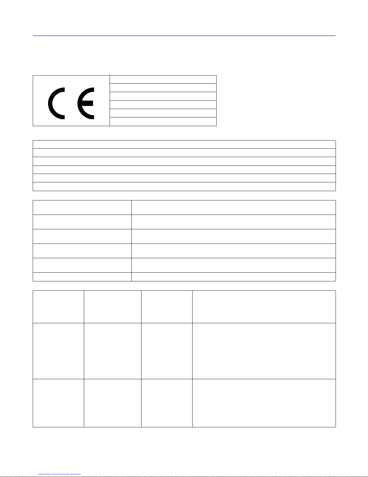
EU-Declaration of Conformity
This product is carrying the CE-Mark in accordance with the related European Directives. Responsible for CE-Marking
is Toshiba Europe, Hammfeldamm 8, 41460 Neuss, Germany.
TOSHIBA
EU Declaration of Conformity
EU Übereinstimmungserklärung
Déclaration de conformité UE
Declaración de conformidad de la UE
Dichiarazione di conformità UE
EU Försäkran om Överensstämmelse
Toshiba declares that the product: Toshiba Magnia 3135R (SYU3709U-RXXXX) conforms to the following standards:
Toshiba erklärt, daß das Produkt: Toshiba Magnia 3135R (SYU3709U-RXXXX) folgenden Normen entspricht:
Toshiba déclarent que le produit cité ci-dessous: Toshiba Magnia 3135R (SYU3709U-RXXXX) est conformé aux normes suivantes:
Toshiba declaran que el producto: Toshiba Magnia 3135R (SYU3709U-RXXXX) cumple los siguientes estándares:
Toshiba dichiara, che il prodotto: Toshiba Magnia 3135R (SYU3709U-RXXXX) è conforme alle seguenti norme:
Toshiba intygar att produkten: Toshiba Toshiba Magnia 3135R (SYU3709U-RXXXX) överensstämmer med föijande normer:
Supplementary Information: “The product complies with the requirements of the Low Voltage Directive 73/23/EEC and the EMC
Directive 89/336/EEC.”
Weitere Informationen: “Das Produkt entspricht den Anforderungen der Niederspannungs-Richtlinie 73/23/EG und der EMC-
Richtlinie 89/336/EG.”
Informations complémentaires: “Ce produit est conforme aux exigences de la directive sur les basses tensions 73/23/CEE et de la
directive EMC 89/336/CEE.”
Información complementaria: “El Producto cumple los requisitos de baja tensión de la Directiva 73/23/CEE y la Directiva EMC 89/
336/CEE.”
Ulteriori informazioni: “Il prodotto é conforme ai requisiti della direttiva sulla bassa tensione 73/23/EG e la direttiva EMC 89/
336/EG.”
Ytteligare information: “Produkten uppfyller kraven enligt lägspänningsdirektiver 73/23/EEC och EMC-direktiv 89/336/EEC.”
EMC-emission: EN50081-1
EN55022
EN61000-3-2
EN61000-3-3
1992
1994
1995
1995
Residential, commercial & Light Industry
Class B (Domestic environment)
230V/AC, 50Hz
230V/AC, 50Hz
EMC-immunity EN55024
EN61000-4-2
EN61000-4-3
EN61000-4-4
EN61000-4-5
EN61000-4-6
EN61000-4-11
1998
1995
1998
1995
1995
1997
1994
Residential, commercial & Light Industry
DO:8kV, AD:15kV
3V/m, 80-1000MHz, 1kHz 80% AM
AC-line: 1kV, Signal-line: 0.5kV, f:5kHz, Polarity: +/AC-line: 1kV/2kV, Polarity: +/3Ve.m.f, 0.15-80MHz, 80% AM
30% 500ms, 100% 10ms, >95% 5000ms
Safety: EN60950
A1
A2
A3
A4
A11
1992
1993
1993
1995
1997
1997
5
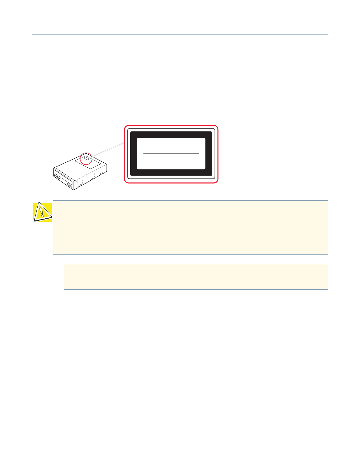
CD-ROM Safety Instruction
The CD-ROM drive employs a laser system. To ensure proper use of this product, please read the CD-ROM instruction
manual carefully and retain for future reference. Should the unit ever require maintenance, contact an authorized
service location. Use of controls, adjustments, or performance of procedures other than those specified may result in
hazardous radiation exposure. To prevent direct exposure to the laser beam, do not try to open the enclosure.
Location of the Required Label
Copyright
This guide is copyrighted by Toshiba America Information Systems, Inc. with all rights reserved. Under the copyright
laws, this guide cannot be reproduced in any form without the prior written permission of Toshiba. No patent liability is
assumed, however, with respect to the use of the information contained herein.
©2001 by Toshiba America Information Systems, Inc. All rights reserved.
CAUTION: This appliance contains a laser system and is classified as a “CLASS 1
LASER PRODUCT.” To use this model properly, read the instruction manual carefully
and keep it for your future reference. In case of any trouble with this model, please
contact your nearest “AUTHORIZED service station.” To prevent direct exposure to the
laser beam, do not try to open the enclosure.
Use of controls or adjustments or performance of procedures other than those
specified in the owner’s manual may result in hazardous radiation exposure.
CLASS 1 LASER
PRODUCT TO IEC 60825-1
LASER KLASSE 1
N
ACH IEC 60825-1
CLASS 1 LASER PRODUCT
LASER KL ASSE 1

6
Export Administration Regulation
This document contains technical data that may be controlled under the U.S. Export Administration Regulations and
may be subject to the approval of the U.S. Department of Commerce prior to export. Any export, directly or indirectly, in
contravention of the U.S. Export Administration Regulations is prohibited.
Disclaimer
The information contained in this manual, including but not limited to any instructions, descriptions, and product
specifications, is subject to change without notice.
TOSHIBA CORPORATION AND TOSHIBA AMERICA INFORMATION SYSTEMS, INC. (TOSHIBA) PROVIDE NO
WARRANTY WITH REGARD TO THIS MANUAL OR ANY OTHER INFORMATION CONTAINED HEREIN AND
HEREBY EXPRESSLY DISCLAIM ANY IMPLIED WARRANTIES OF MERCHANTABILITY OR FITNESS FOR ANY
PARTICULAR PURPOSE WITH REGARD TO ANY OF THE FOREGOING. TOSHIBA ASSUMES NO LIABILITY
FOR ANY DAMAGES INCURRED DIRECTLY OR INDIRECTLY FROM ANY TECHNICAL OR TYPOGRAPHICAL
ERRORS OR OMISSIONS CONTAINED HEREIN. IN NO EVENT SHALL TOSHIBA BE LIABLE FOR ANY
INCIDENTAL, CONSEQUENTIAL, SPECIAL, OR EXEMPLARY DAMAGES, WHETHER BASED ON TORT,
CONTRACT, OR OTHERWISE, ARISING OUT OF OR IN CONNECTION WITH THIS MANUAL OR ANY OTHER
INFORMATION CONTAINED HEREIN OR THE USE THEREOF.
Some states do not allow the exclusion of incidental or consequential damages so the above limitation or exclusion
may not apply to you.
Trademarks
Magnia is a trademark and InTouch is a service mark of Toshiba America Information Systems, Inc.
Intel, Pentium, and LANDesk are registered trademarks of Intel Corporation.
PS/2 is a trademark of International Business Machines Corporation.
Microsoft, its logos, MS-DOS, Windows, and Windows NT, and MS are registered trademarks of Microsoft Corporation.
Ethernet is a registered trademark of Xerox, Inc.
EZ-SCSI and SCSISelect are registered trademarks of Adaptec, Inc.
NetWare is a registered trademark of Novell Corporation.
“Acrobat
®
Reader Copyright © 1987-1999 Adobe Systems Incorporated. All rights reserved. Adobe, the Adobe logo,
Acrobat, and the Acrobat logo are trademarks of Adobe Systems Incorporated.”
Other product names and trademarks belong to the individual companies concerned.

7
Table of Contents
About This Guide....................................................................................... 14
Other Documentation and Software .......................................................... 15
Safety Icons............................................................................................... 15
Other Icons....................................................................................... 16
Service Options ......................................................................................... 16
Maintenance Contracts ............................................................................. 16
Cleaning the Server................................................................................... 16
Setting Up Your Work Environment........................................................... 16
Developing Good Work Habits......................................................... 17
Arranging Your Work Area ............................................................... 17
Seating and Posture......................................................................... 18
Using Your Arms and Wrists ............................................................ 18
Chapter 1: Getting Started.................................................................. 19
Make Sure You Have Everything............................................................... 19
Installing Optional Internal Devices........................................................... 19
Environmental Considerations .................................................................. 19
General Environmental Considerations ........................................... 19
Environmental Considerations for Rack Mount Models............... 21
Power Requirements................................................................................. 21
Front Panel................................................................................................ 22
Toshiba Magnia 3135R Mounted in a Rack ................................22
Controls and Indicators .................................................................... 23
Operation Buttons........................................................................ 23
System and HDD Status Indicators .............................................24
Determining Network Communication Status (NIC LEDs) .......... 25
Device Bays................................................................................. 25
CD-ROM Drive ............................................................................ 25
Floppy Disk Drive ........................................................................ 26
Cooling Fan Unit........................................................................................ 27
Rear Panel ....................................................................................... 28
Identifying the AC Power Connector and I/O Signal Ports ..........28
Using USB-Compliant Devices.................................................... 29
Inside the Server ....................................................................................... 29

8
Motherboard..................................................................................... 30
CPU Sockets.................................................................................... 30
Internal Battery................................................................................. 30
Memory Bank ................................................................................... 30
Expansion Slots ............................................................................... 30
Cabling the Server Board ............................................................ 31
Connecting Peripheral Devices ...................................................33
Installing the Server in a Rack................................................................... 34
Choosing a Location ........................................................................ 34
Structural Considerations ............................................................ 34
Environmental Considerations..................................................... 34
Power Considerations ...................................................................... 35
Preparing the Rack.................................................................................... 35
Selecting a Location for the Server in the Rack ............................... 36
Equipment Mounting Guidelines ...................................................... 36
Stabilizing the Rack ................................................................................... 37
Free-Standing Stabilizers ................................................................. 37
Secured Stabilizers .......................................................................... 37
Recommended Tools ....................................................................... 38
Toshiba-Supplied Hardware Items ..............................................38
Installing the Rail Rack and Mounting the Server ..................................... 39
Connecting AC Power ............................................................................... 43
Installation Checklist ........................................................................ 43
Power Consumption Checklist ......................................................... 44
Turning on the Server................................................................................ 45
Power-On Self Test (POST) ...................................................................... 45
Booting the Server..................................................................................... 46
Starting the Server From the Floppy Disk Drive............................... 46
Starting the Server From the CD-ROM Drive................................... 46
Starting the Server From the Hard Disk Drive.................................. 46
BIOS Setup ............................................................................................... 47
Turning Off the Server ............................................................................... 47
Performing a Normal Shutdown ....................................................... 47
Chapter 2: Connecting Hardware Devices ......................................... 48

9
Contents ...................................................................................... 48
Installing Optional Devices ........................................................................ 49
Before You Start ............................................................................... 49
Selecting a Workplace................................................................. 49
Working Safely ............................................................................ 50
Maintenance Overview.............................................................................. 50
Working on Rack Mounted Servers ................................................. 51
Sliding the Server From the Rack................................................ 52
Sliding the Server into the Rack .................................................. 52
Removing and Replacing the Server Access Cover ................................. 53
Removing the Access Cover............................................................ 53
Replacing the Access Cover ............................................................ 54
Cooling Fans ............................................................................................. 54
Removing and Replacing a System Fan.......................................... 54
Removing a System Fan ............................................................. 54
Replacing a System Fan ............................................................ 55
Memory Modules....................................................................................... 56
Memory Expansion Considerations ............................................56
Installing Memory Modules .......................................................... 58
Removing a Memory Module ........................................................... 60
CPU Modules ............................................................................................ 61
Installing a Second Processor.......................................................... 61
Removing a Processor..................................................................... 67
Installing Hard Drives ................................................................................ 68
Internal Battery .......................................................................................... 69
Replacing the Internal Battery.......................................................... 71
Peripheral Devices .................................................................................... 72
Floppy Diskette Drive (FDD) ............................................................ 72
Removing the Diskette Drive ....................................................... 72
Reinstalling the Diskette Drive..................................................... 72
Removing and Replacing the CD-ROM Drive.................................. 73
Removing a CD-ROM Drive ........................................................ 73
Replacing a CD-ROM Drive ........................................................ 73
Small Computer Systems Interface (SCSI) ............................................... 74
Internal Hard Disk Drives (HDD) ...................................................... 74
Detecting the SCSI Device (SAF-TE) .............................................. 74

10
Terminating SCSI Devices ............................................................... 74
Downgraded Server Operation ........................................................ 75
RAID 0 - Disk Striping.................................................................. 75
RAID 1 - Disk Mirroring................................................................ 75
RAID 5 - Disk Striping With Distributed Parity ............................. 76
RAID 10 - Disk Striping and Disk Mirroring ................................. 76
RAID Failures................................................................................... 76
Striping Configuration Failure (RAID 0) ....................................... 76
Mirrored Drive RAID Configuration Failure (RAID 1)...................77
Parity RAID Configuration Failure (RAID 5) ................................ 77
If the Server Does Not Have a RAID Controller .......................... 77
Expansion Cards ....................................................................................... 78
Restrictions on PCI Expansion Cards .............................................. 78
Installing Add-in Cards ..................................................................... 79
Installing a RAID Controller.............................................................. 81
Chapter 3: System Configuration Setup............................................. 82
Hot Keys.................................................................................................... 82
Power-On Self Test (POST) ...................................................................... 83
BIOS Setup Utility...................................................................................... 84
Starting the BIOS Setup Utility ......................................................... 84
BIOS Setup Utility Menu Options ................................................ 85
BIOS Setup Utility Keyboard Commands....................................85
Changing BIOS Settings .................................................................. 85
BIOS Settings................................................................................... 86
Main Menu .................................................................................. 86
Advanced Menu........................................................................... 87
Security Menu.............................................................................. 90
System Menu............................................................................... 91
Boot Menu ................................................................................... 92
Exit Menu..................................................................................... 93
Upgrading the BIOS ......................................................................... 93
Using the Adaptec SCSI Utility.................................................................. 94
Starting the SCSI Utility.................................................................... 94
Menu Configuration.......................................................................... 94
SCSI Utility Keyboard Commands ................................................... 95
Changing SCSI Device Settings ...................................................... 95

11
Setting Devices ................................................................................ 95
Chapter 4: Hardware Diagnostics ...................................................... 98
About the Diagnostics Utility...................................................................... 98
Starting Hardware Diagnostics .................................................................. 98
Starting up Using the Diskette.......................................................... 98
Diagnostic Options .................................................................................... 99
01. Diagnostic Test......................................................................99
02. Running Test .........................................................................99
03. Log Utilities............................................................................99
04. System Configuration ............................................................ 99
99. Exit......................................................................................... 99
01. Diagnostic Test.................................................................................. 100
01. Diagnostic Test Menu Test Items ............................................. 100
01. Memory Test........................................................................ 100
02. Keyboard Test ..................................................................... 105
03. Display Test ......................................................................... 108
04. Floppy Disk Test.................................................................. 111
05. Printer Test .......................................................................... 114
06. SCSI HDD Test ................................................................... 115
07. NPX Test ............................................................................. 118
08. Cache Test .......................................................................... 120
09. SCSI Test ............................................................................ 124
10. CD-ROM Test...................................................................... 125
11. SAF-TE Test........................................................................ 128
12. SMC Test............................................................................. 129
02. Running Test ..................................................................................... 132
03. Log Utilities........................................................................................ 134
Log Utilities screen headings ......................................................... 134
Key Operation for Log Utilities...................................................138
System Configuration Display ................................................................. 139
System Information ........................................................................ 139
SCSI Devices ................................................................................. 141
System Configuration Information.................................................. 141
MAIN Chassis............................................................................ 141
Chapter 5: Software Installation ....................................................... 142
Startup ..................................................................................................... 142

12
Creating Floppy Diskettes for Drivers and Utilities......................... 142
Windows NT Server 4.0 .......................................................................... 143
Installing Drivers............................................................................. 144
Onboard SCSI Controller ............................................................... 144
Express 500 RAID Controller......................................................... 144
RAID Controller .............................................................................. 145
Onboard Network Adapter ............................................................. 145
After Windows NT 4.0 is installed .................................................. 146
Service Pack.............................................................................. 146
Video Driver............................................................................... 146
Other steps to take .................................................................... 146
Optional Software........................................................................... 147
Re-Installing Adapter Drivers ......................................................... 147
Onboard SCSI Controller...........................................................147
Intel Pro100NT Driver................................................................148
Windows 2000 Server ............................................................................. 149
Express 500 RAID Controller......................................................... 149
Installing Toshiba Display Power Save Driver................................ 150
After Windows 2000 Server is installed.......................................... 150
Installing Netware.................................................................................... 151
Motherboard settings ..................................................................... 151
Floppy disk preparation .................................................................. 151
Manually installing NetWare 5.1..................................................... 151
Selecting the driver .................................................................... 151
Selecting a RAID Controller driver............................................. 151
Selecting a SCSI Controller driver............................................. 152
Selecting the RAID Controller driver .............................................. 153
Selecting a Network Adapter driver ........................................... 154
Post installation procedures ........................................................... 154
Setup the RAID Controller Utility ............................................... 154
Chapter 6: If Something Goes Wrong .............................................. 155
Identifying a Problem............................................................................... 155
Startup Sequence.................................................................................... 156
Error Checking ............................................................................... 156
Startup Problems............................................................................ 156

13
Application Software Problems ............................................................... 157
After the System Has Been Running Correctly .............................. 158
Common Hardware Problems ................................................................. 158
The Power Indicator Does Not Light .............................................. 158
The Screen is Blank....................................................................... 159
Characters are Distorted or Do Not Display Properly .................... 159
The FDD Activity Indicator Does Not Light..................................... 159
The FDD Activity Indicator is Always On........................................ 160
The HDD Status Indicators Do Not Light........................................ 160
The HDD Does Not Respond......................................................... 160
CD-ROM Drive Status Indicator Does Not Light ............................ 160
Before Calling for Service........................................................................ 160
Toshiba Technical Support ...................................................................... 161
Appendix A: Specifications .............................................................. 162
Appendix B: Interface ...................................................................... 170
Appendix C: Jumper Settings .......................................................... 173
Appendix D: Unit Logs ..................................................................... 178
Appendix E: Rack Template ............................................................ 181

About This Guide 14
Introduction
Thank you for purchasing the Toshiba Magnia 3135R server, which combines high
performance with great flexibility.
❖ The Toshiba Magnia 3135R is designed around the ServerWorks
®
ServerSet III LE
(FSB 133 MHz).
❖ The 3135R supports up to two Intel
®
Pentium III processors.
❖ Flex PCI riser card with one 64 bit/66 MHz slot and one 32 bit/33 MHz slot provide
add-in board capability.
❖ The integrated onboard video controller has 4MB of video memory.
❖ The 3135R comes with an integrated onboard Network Interface Controller (NIC),
using an Intel
®
82559 single chip PCI LAN controller for 10 or 100 Mbps TX Fast
Ethernet networks.
❖ Thermal/voltage monitoring and error handling are provided.
❖ Front panel controls and indicators (LEDs) are present for system operation.
❖ The 3135R includes an onboard SCSI controller with Adaptec AIC-7899 supporting
onboard Ultra160 and Ultra-wide SCSI Interfaces.
❖ Memory is expandable from 128 MB to 4GB using registered DIMMs.
About This Guide
This guide introduces the features of the Toshiba Magnia 3135R server and explains how
to set up, configure, and maintain the server. Before using your Toshiba server, refer to
this guide to gain an overall understanding of operating procedures and safety
precautions.
Other Documentation and Software 15
Other Documentation and Software
In addition to this user’s guide, Toshiba provides a system CD that contains:
❖ The Safety Instruction Guide for Toshiba Servers, which contains general safety
information.
Toshiba also provides you with:
❖ A Toshiba Magnia™ 3135R Quick Start Card, which identifies the major server
components, and provides a quick reference on connection, setup, and system
configuration information.
❖ Warranty information
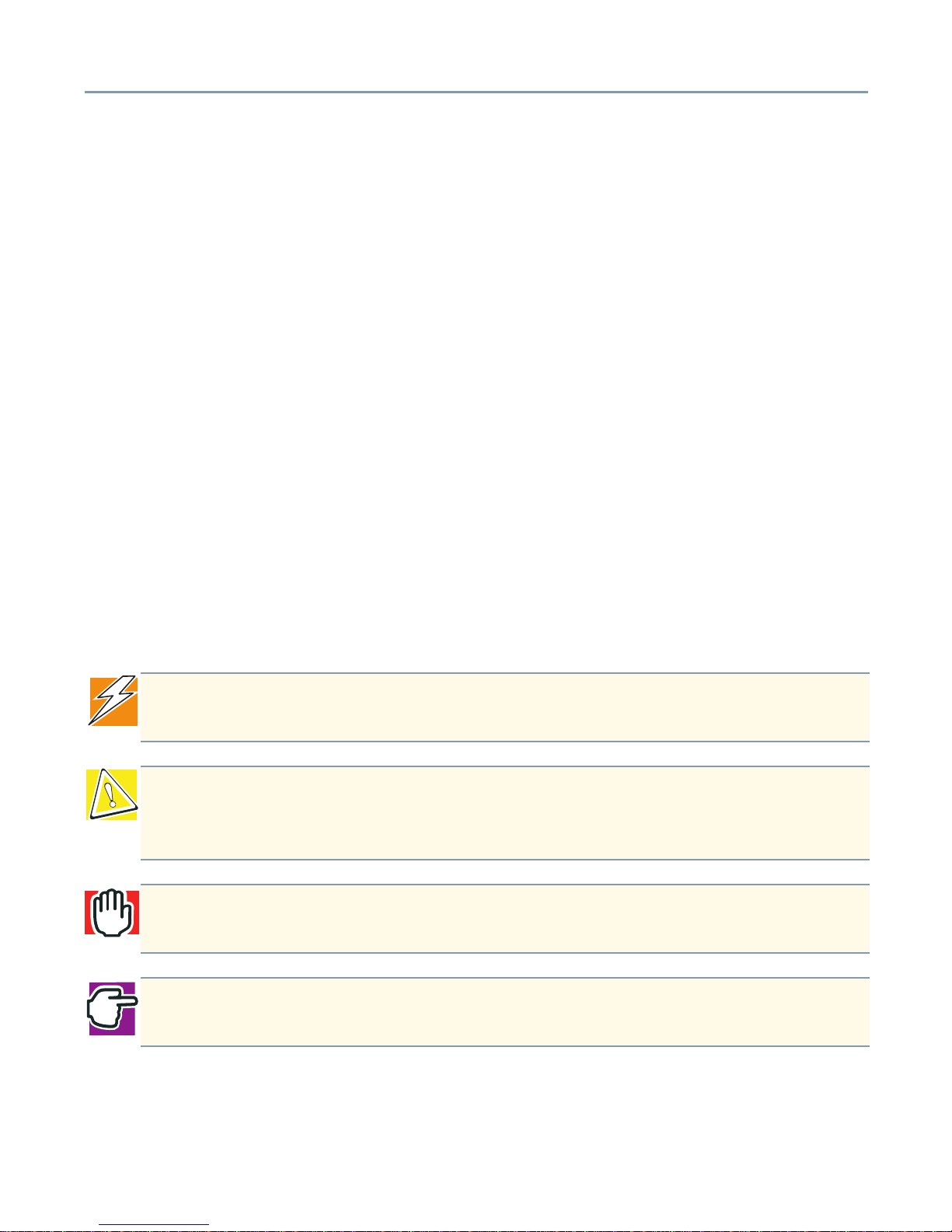
Safety Icons
Read and understand all safety instructions before attempting to use your Toshiba
Magnia 3135R server.
This guide contains the safety instructions that must be observed in order to avoid
personal injury or damage to your server. The safety instructions have been classified
according to the seriousness of the risk, and the following icons highlight these
instructions.
It is extremely important to follow basic safety practices are followed when installing and
maintaining the system.
DANGER: This icon indicates the existence of a hazard that could result in death or
serious bodily injury if the safety instruction is not observed.
CAUTION: This icon indicates the existence of a hazard that could result in damage
to equipment or property if the safety instruction is not observed. A caution also
indicates a potential loss of data.
WARNING: This icon indicates the existence of a hazard that could result in bodily
injury if the safety instruction is not observed.
NOTE: This icon indicates information that relates to the safe operation of the
equipment or related items.
Service Options 16
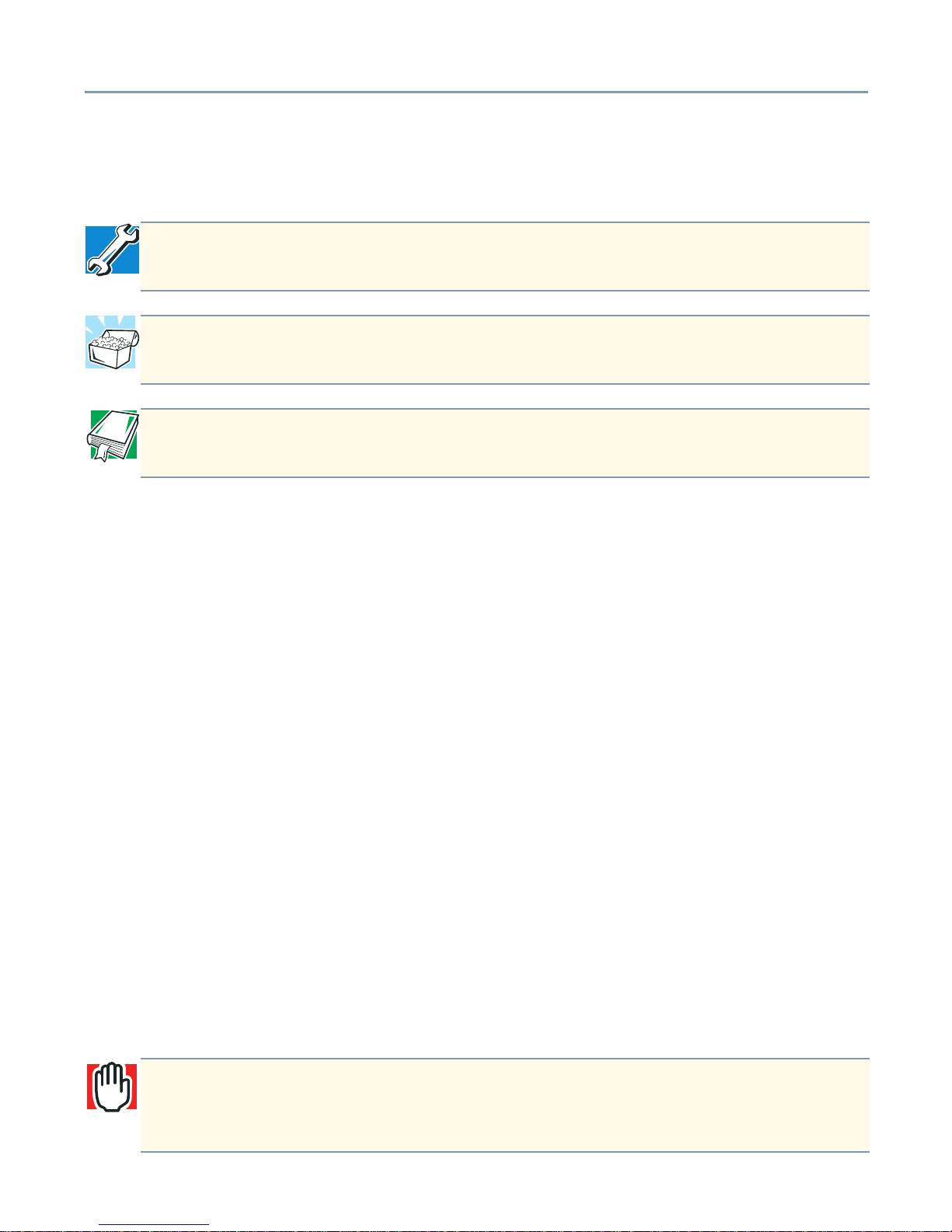
Other Icons
Additional icons highlight other helpful or educational information:
Service Options
Toshiba offers a full line of service options built around its warranty programs. For
registration information refer to the warranty and service material included with the
server, or go to our web site at: http://www.support.toshiba.com.
Maintenance Contracts
Periodic maintenance and inspection is essential to keeping the server fully operational
and assuring its safe use. Toshiba recommends taking out a maintenance contract with
an authorized Toshiba Magnia service provider.
Cleaning the Server
If the server’s exterior case is dirty or stained, clean it with a soft cloth. If necessary,
moisten the cloth with water. Never use harsh chemicals to clean the server.
Setting Up Your Work Environment
You can work more comfortably and efficiently by thoughtfully organizing your work
space. Developing good work habits is the best way to avoid strain and stress to your
hands, back, neck and eyes.
TECHNICAL NOTE: This icon highlights technical information about the server.
HINT: This icon denotes helpful hints and tips.
DEFINITION: This icon indicates the definition of a term used in the text.
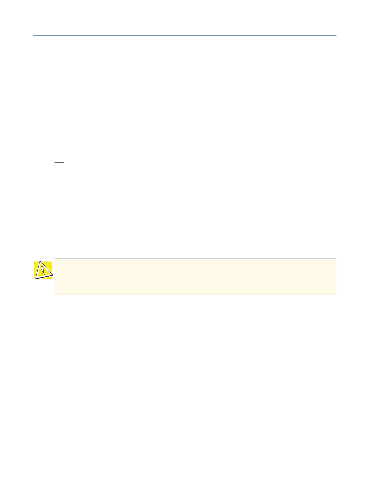
WARNING: Using the computer keyboard incorrectly may result in discomfort and
possible injury. If your hands, wrists, and/or arms bother you while typing, stop
using the computer and rest. If the discomfort persists, consult a physician.

Setting Up Your Work Environment 17
Developing Good Work Habits
The key to avoiding discomfort or injury from repetitive strain is to vary your activities. If
possible, schedule a variety of tasks into your working day. Finding ways to break up the
routine can reduce stress and improve your efficiency.
❖ Take pauses from typing.
❖ Take short breaks to change position, stretch your muscles, and rest your eyes. A two
or three minute break every half hour is more effective than one long break after
several hours.
❖ Stretch spontaneously throughout the day to reduce tension.
❖ Avoid performing repetitive activities for long periods. Intersperse repetitive activities
with other tasks.
❖ Look away from the computer every 15 minutes or so to reduce eye strain, and focus
your eyes on a distant object for 30 seconds.
Arranging Your Work Area
Carefully planned placement of your computer and desktop tools can help you avoid
stress-related injuries and help you work more efficiently. Adjusting the lighting can make
it easier to see your work and reduce eye strain.
❖ Place the keyboard on a flat surface, directly in front of you, at a comfortable distance.
When you use the keyboard, your arms and hands should be in a relaxed position
with your forearms parallel to the floor. You should be able to type without twisting
your body or neck.
❖ Place the monitor so that its top is at eye level. If you wear bifocal or progressive
lenses, position the monitor slightly lower.
❖ Set your paper holder at the same distance as the screen. If possible, adjust the
holder so that the paper is at the same height as the screen.
❖ Position the monitor so that sunlight or bright indoor lighting does not reflect off the
screen. Use tinted windows or shades to reduce glare.
❖ Adjust the screen to avoid reflections and glare.
❖ Avoid placing the monitor in front of a bright light that could shine directly in your eyes.
❖ If possible, use soft, indirect lighting in your computer work area.
Setting Up Your Work Environment 18
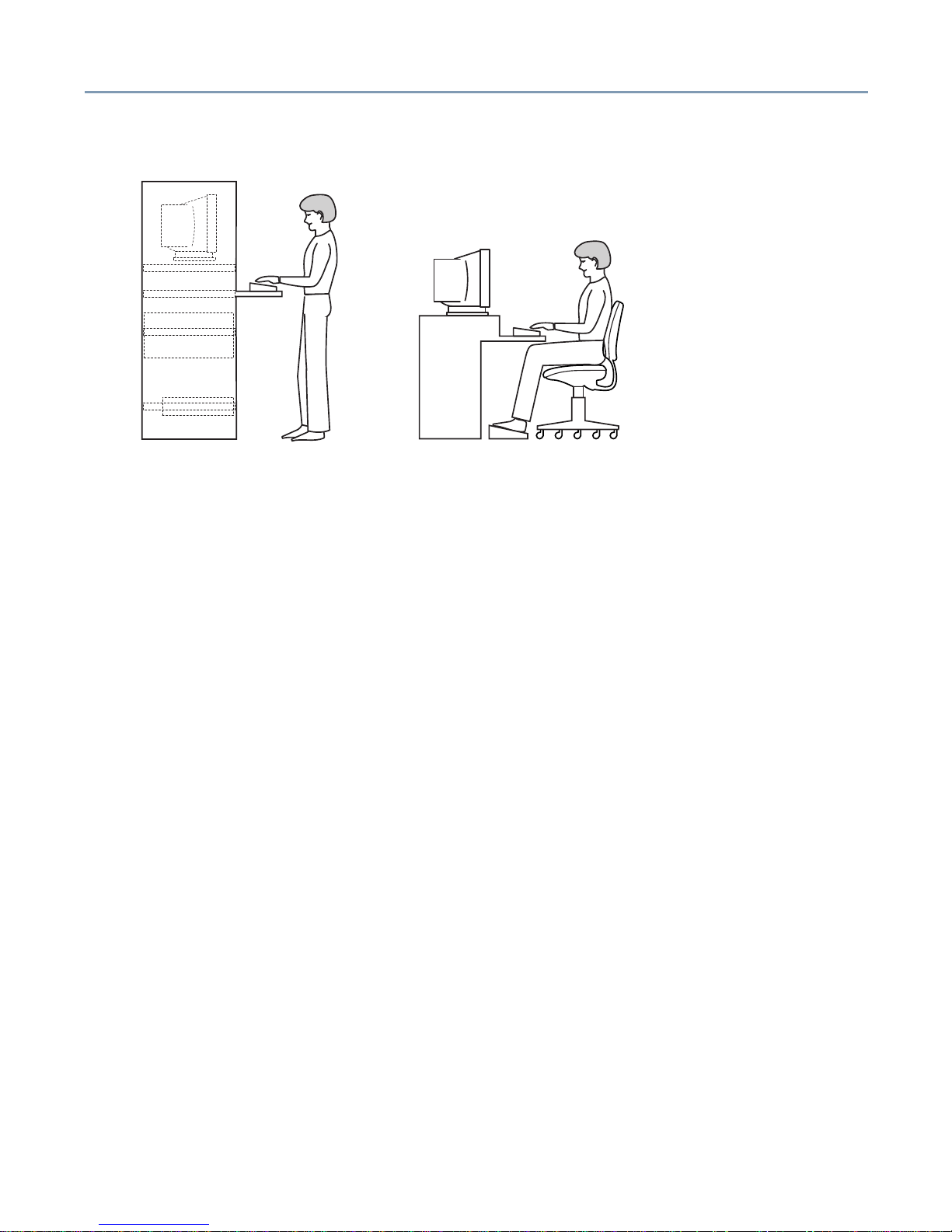
Seating and Posture
Correct posture and computer placement
When using the computer, sit comfortably. Proper seating is a primary factor in reducing
strain.
❖ Position your chair so that the keyboard is at or slightly below the level of your elbow.
You should be able to type comfortably with your shoulders relaxed.
❖ Position your knees should be slightly higher than your hips. If necessary, use a
footrest to raise the level of your knees and ease the pressure on the back of your
thighs.
❖ Adjust the back of your chair so that it supports the lower curve of your spine. If
necessary, use a cushion to provide extra back support.
❖ Sit with your back straight so that your knees, hips and elbows form approximately
90-degree angles when you work. Do not slump forward or lean back too far.
Using Your Arms and Wrists
Regular attention to your work habits can make your time at the computer more
productive.
❖ Keep your wrists straight while typing. If necessary, adjust the keyboard and chair
height to keep wrists straight.
❖ Avoid resting on your wrists while typing.
❖ Use a light touch on the keys and mouse.
❖ Avoid bending, arching, or twisting your wrists. Keep them in a relaxed, neutral
position while typing.
❖ Exercise your hands, wrists and arms several times during the day to improve
circulation.

19
Chapter 1
Getting Started
This chapter provides a detailed description of the server and the environmental
conditions in which it is designed to operate.
Make Sure You Have Everything
Unpack the boxes and check the contents against your purchase order. If the server
contains optional devices, those components will also be listed. If any items are missing
or damaged, notify your Toshiba representative immediately.
Installing Optional Internal Devices
Install all optional devices before setting up the server. The installation and configuration
procedures described in this guide require specific technical knowledge and experience.
If you have no experience installing and removing computer hardware devices, or if the
job seems difficult, consult an authorized Toshiba Magnia service provider. Toshiba
assumes no liability for damages if you install and remove optional devices yourself.
Environmental Considerations
This section lists precautionary measures that should be followed when setting up rackmounted Toshiba Magnia 3135R servers.
General Environmental Considerations
❖ Install the server in a clean, dust-free and well-ventilated place.
❖ Install the server on a level and steady surface.
❖ Never install the server upside down.
Getting Started Environmental Considerations 20
❖ Never install the server in any of the following places:
- Where it will be exposed to direct sunlight
- Where it will be exposed to vibration or shock
- Near any devices that generate a strong magnetic field or produce radio
frequency noise such as a radio, TV, large motor or loudspeaker
- Where the temperature and humidity change constantly; for example, near an airconditioning vent, fan, heater or heat source
- Near liquids or corrosive chemicals
If debris or liquid gets in the server, shut it down immediately by turning the power button
Off
and unplugging the power cable from the AC outlet. Do not turn the server back on.
Contact an authorized Toshiba Magnia service provider immediately.
Operate the server under the following temperature and humidity conditions:
Ambient temperature:
The operating temperature of the server, when installed in an equipment rack,
must not go below 5 °C (41 °F) or rise above 32 °C (89 °F).
Relative humidity:
30% to 80% Rh (no condensation)
Ventilation:
The equipment rack must provide sufficient airflow to the front of the server to
maintain proper cooling. It must also include ventilation sufficient to exhaust a
maximum of 1,500 BTU per hour for each server. The rack selected and the
ventilation provided must be suitable to the environment in which the server is
used.
To avoid damage from condensation when the room temperature is too high or too low,
wait about an hour before turning the server on. The delay allows the server to adjust to
the ambient room conditions.
CAUTION: Avoid exposing the server to condensation during use and storage.
Condensation can corrode server components and short-circuit its electrical circuits
if the unit is on.
Getting Started Power Requirements 21
Environmental Considerations for Rack Mount Models
In addition to the general environmental considerations, keep these additional points in
mind:
❖ Use the optional Toshiba rack and rack mounting kit to install a rack model server.
❖ Provide sufficient airflow to the server to maintain proper cooling. Allow 51 inches
(130 cm) of clearance in front of, and 24 inches (60 cm) behind the rack.
For more information on environmental considerations for a rack-mounted server, see
Environmental Considerations on page 34 and Selecting a Location for the Server in the
Rack on page 36.
Power Requirements
The power supply unit has maximum current ratings of 4.6 amperes with input voltages
of 100-200 volts (at 50/60 Hz), or 2.3 amperes with input voltages of 200-240 volts (at 50/
60 Hz), with 10 amp over-current protective circuits.
Before plugging the power cable into a wall outlet, make sure that the AC power source
and the over-current protector (circuit breaker current rating) are sufficient to handle the
requirements of the server and its connected peripheral devices.
The current rating of the server is 4 amps. To ensure a continuous supply of power to the
server, Toshiba recommends the use of an uninterruptible power supply (UPS).
If you have questions about the wiring of your AC power source, consult an authorized
Toshiba Magnia service provider.
NOTE: Installing a Toshiba Magnia 3135R in a rack requires special knowledge and
skills. Toshiba recommends that you contact an authorized Toshiba Magnia service
provider.
WARNING: To ensure proper grounding of the server and avoid a possible fire
hazard, use the power cable provided with the server.
Getting Started Front Panel 22
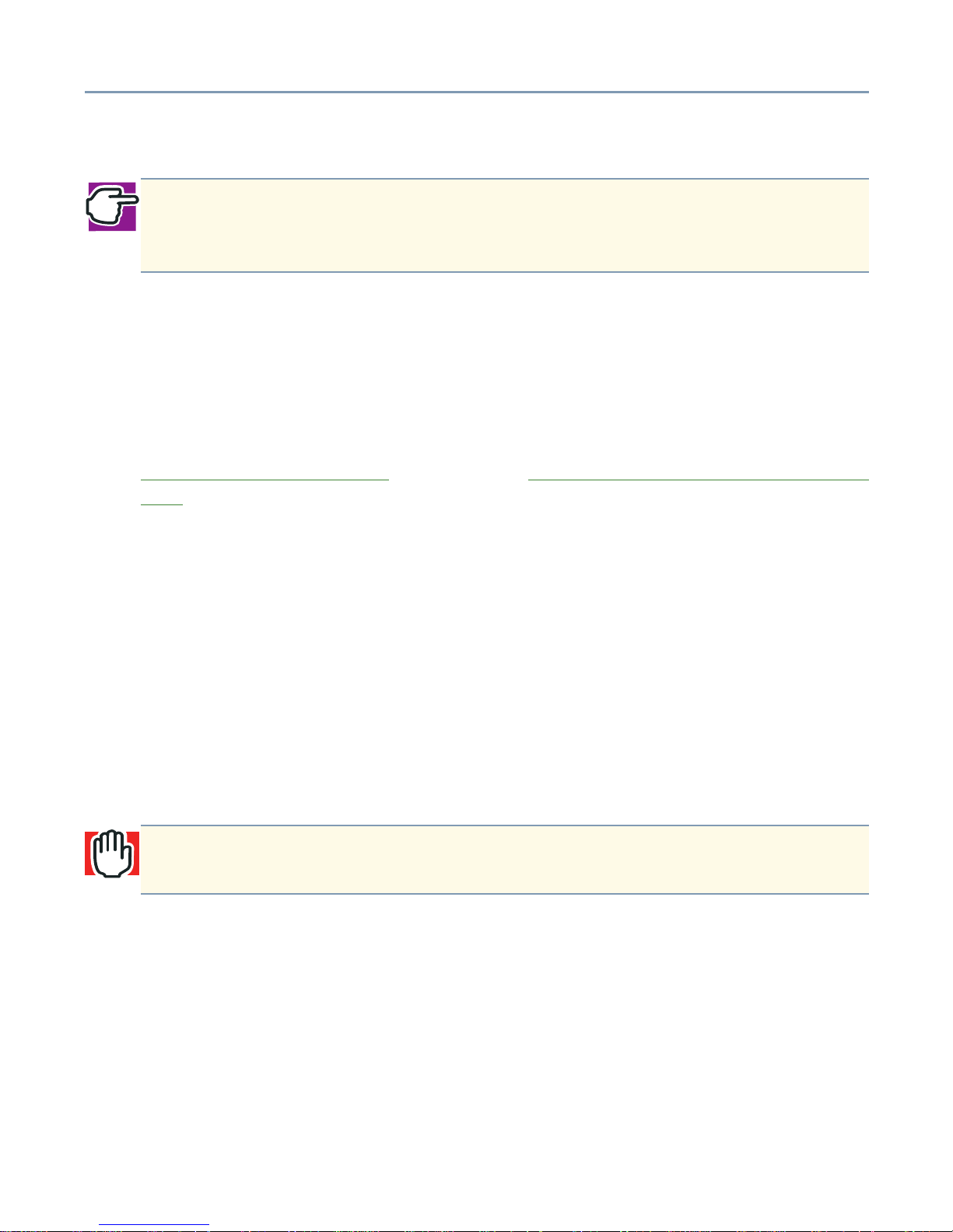
Front Panel
Front Panel
The front panel provides protection for, and access to, the controls and indicators, as well
as the drive bays containing the hard disk drive (HDD), the CD-ROM drive, and a floppy
disk drive (FDD).
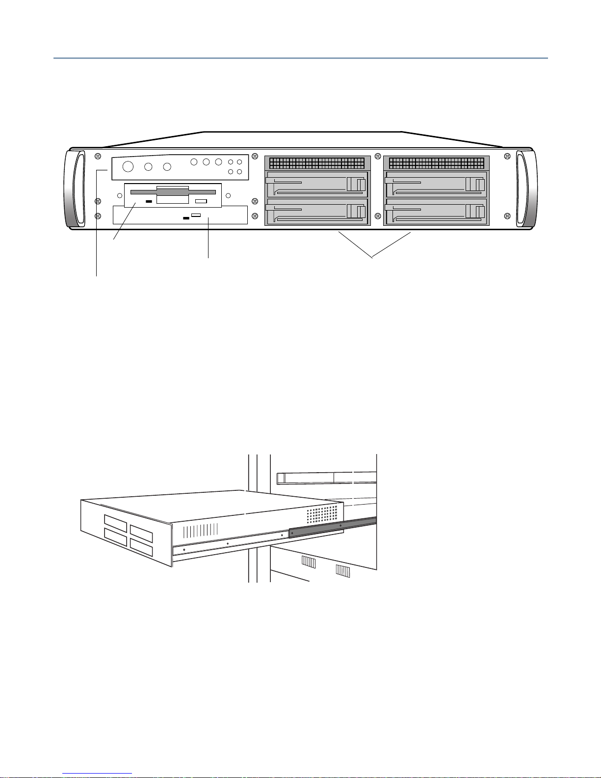
Toshiba Magnia 3135R Mounted in a Rack
Rack Mounted Server
Drive Bays
Floppy Drive
CD-ROM Drive
Controls & Indicators

Getting Started Front Panel 23
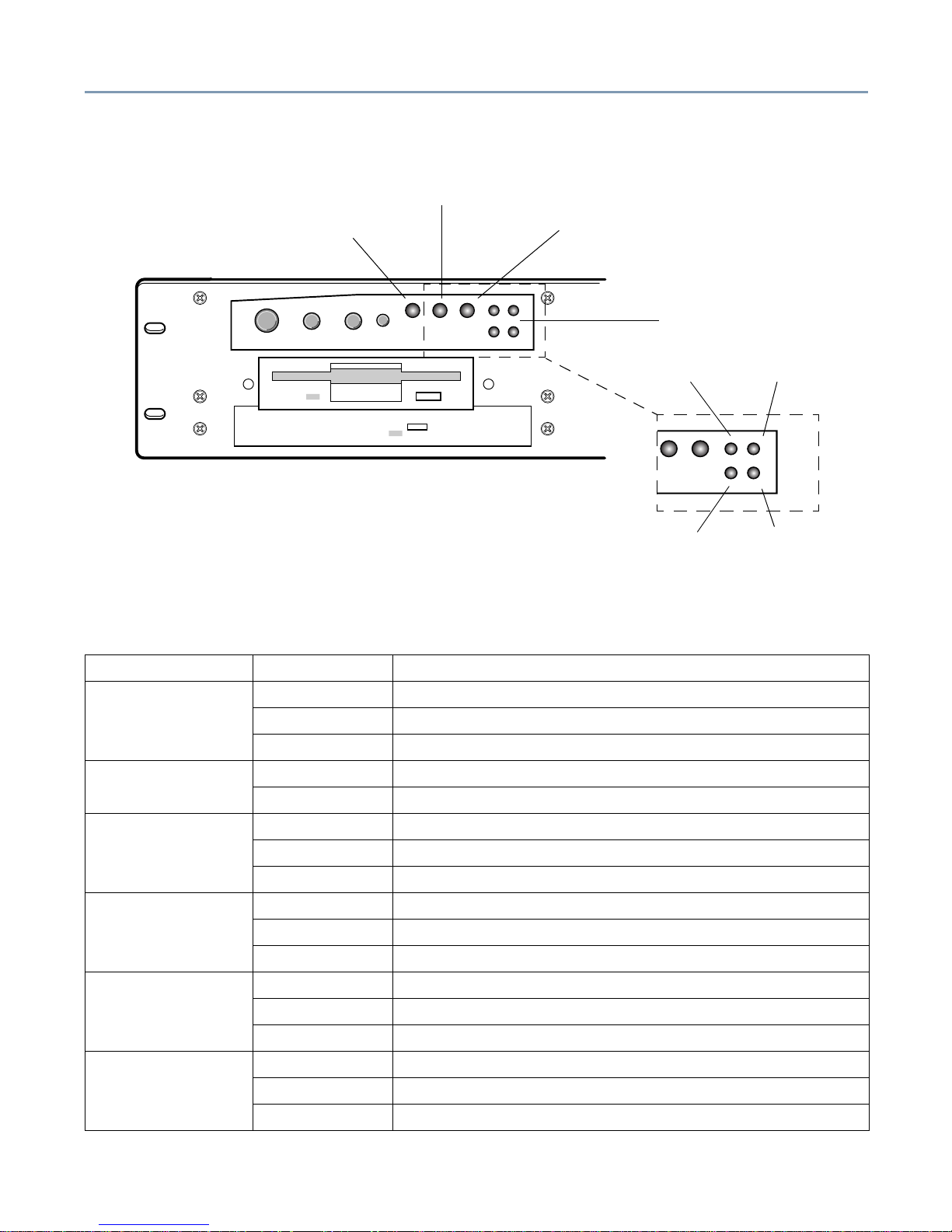
Controls and Indicators
The front panel contains four operation control buttons and seven system indicator LEDs.
Operation Buttons
Operation buttons
Power button - Press this button to power-down the server. Placing the server in
security mode disables the power button. To power-down the server while it is in secure
mode, the user must have shutdown rights. To reactivate the power button, enter your
user password.
Sleep button - Toggles the server between normal operation mode and power-saving
mode (sleep mode). Placing the server in secure mode disables the sleep button. To
place the server in sleep mode while in secure mode, you must have sleep rights. To
reactivate the sleep button, enter your user password.
Reset button - Restarts the server. Placing the server in security mode disables the
Reset button. To re-enable the Reset button, enter your user password.
NMI button - This is a system control button, to be used by authorized Toshiba Service
personnel only.
TECHNICAL NOTE: The procedure for shutting down the server depends on the
operating system installed on the server. For more information on turning the server
on and off, see Turning on the Server
on page 45.
CAUTION: To avoid data loss or corruption, never use the Reset button while the
activity indicator on the floppy disk drive, CD-ROM drive, or hard disk drive is on.
Sleep Button
Power Button
Reset Button
NMI Button
Getting Started Front Panel 24
System and HDD Status Indicators
System indicators
The following table describes the operation of the system indicators.
Indicator Status Description
Power
Off System power off
Green Server is running normally
Flashing Green ACPI standby mode
NIC Activity
Off No LAN activity
Green Network Interface Controller active
System Fail
Off Normal
Amber System Failed
Flashing Amber System warning
Disk Activity/Fail
(0)
Off No power supplied to SCSI drive
Green SCSI drive active
Amber SCSI drive failed
Disk Activity/Fail
(1)
Off No power supplied to SCSI drive
Green SCSI drive active
Amber SCSI drive failed
Disk Activity/Fail
(2)
Off No power supplied to SCSI drive
Green SCSI drive active
Amber SCSI drive failed
Fail LED
Disk Activity/Fail LEDs
NIC Activity LED
Power LED
HDD 3
HDD 0
HDD 1
HDD 2
Getting Started Front Panel 25
Determining Network Communication Status (NIC LEDs)
Device Bays
The Toshiba Magnia 3135R supports five device bays. Four are "Hot Swap" bays,
supporting up to four Hard Disk Drives. The other device bay contains a Floppy Disk
Drive and a Slim CD-ROM.
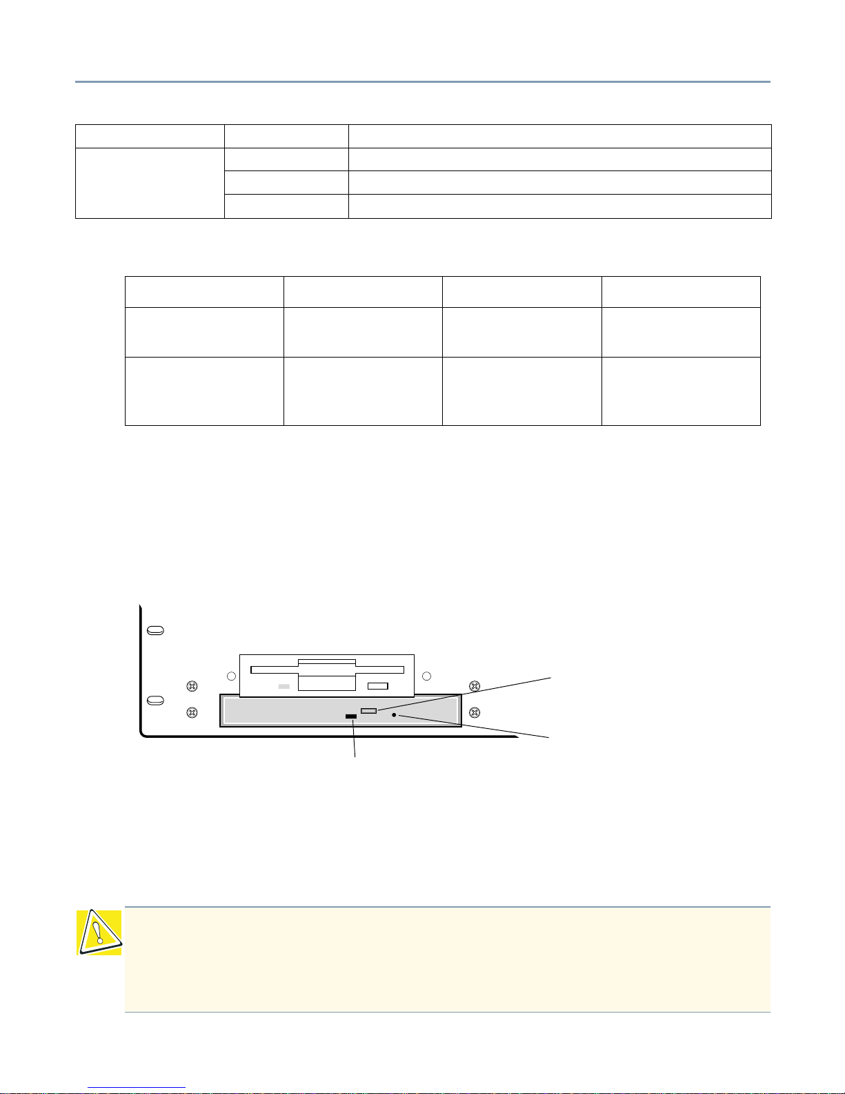
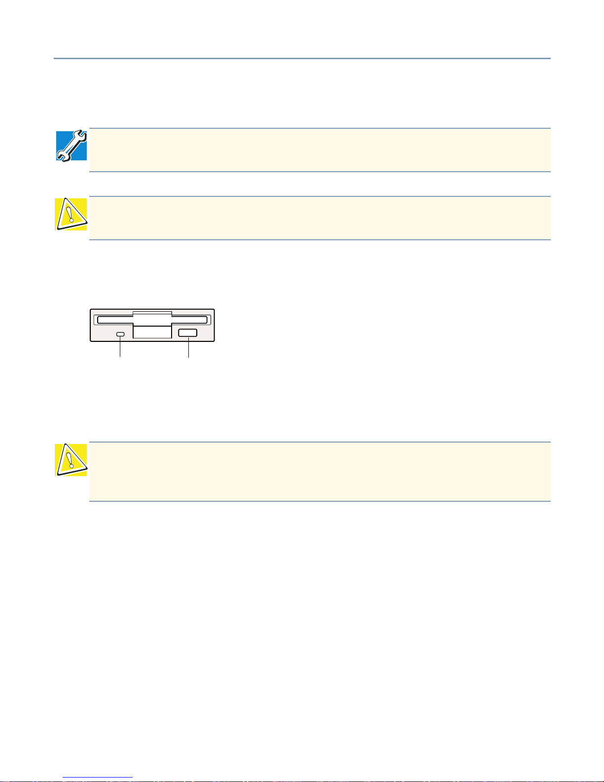
CD-ROM Drive
Front View of CD-ROM buttons and indicator
Manual eject pinhole - Use to manually release the disc tray if it does not open when
you press the eject button while the server is on. To release the disc tray, insert a slender
object, such as a straightened paper clip, through the pinhole and press gently.
Disk Activity/Fail
(3)
Off No power supplied to SCSI drive
Green SCSI drive active
Amber SCSI drive failed
LED Color LED On LED Blinking LED Off
Amber 100-Mbps network
connection
N/A 10-Mbps network
connection
Green Linked to network,
no network traffic
Linked to network,
sending or
receiving data
Not linked to
network
CAUTION: To avoid damage to the CD-ROM drive when manually ejecting a
compact disc, turn off the server before manually opening the disc tray. Never use
pointed objects to release the disc tray. The object could break and damage the
drive. Always remember to remove the CD whenever the drive is not in use.
Indicator Status Description
CD-ROM eject button
CD-ROM activity LED
Manual eject pinhole
Getting Started Front Panel 26
Activity indicator - Illuminates when the CD-ROM is being accessed.
Eject button - Used to open and close the disc tray.
Floppy Disk Drive
The FDD supports 3.5-inch, double-density (720-KB), and high-density (1.44-MB)
diskettes.
Activity indicator - Illuminates whenever the floppy disk drive reads or writes data.
Eject button - Releases the diskette from the drive.
TECHNICAL NOTE: Be sure to verify that any CD is inserted flatly into the drive tray
to avoid damaging the media when the tray closes.
CAUTION: To avoid damaging the CD-ROM drive, never press the eject button
while the status indicator is on.
CAUTION: To avoid losing or corrupting data stored on the diskette, never press the
eject button while the FDD indicator is on. Always remove the diskette from the
floppy disk drive whenever the drive is not in use.
Eject
Activity
indicator
button

Getting Started Cooling Fan Unit 27
Cooling Fan Unit
To regulate the temperature inside the server, theToshiba Magnia 3135R is equipped
with the following cooling fans:
❖ Two 80mm system fans mounted in the middle of the chassis
❖ Power Supply fan internal to the power supply
❖ One CPU fan mounted on each processor
Removal and replacement of a system fan is easily accomplished by powering the
system down, removing the top cover, and removing the fan assembly. There is also a
cooling fan internal to the power supply.
Getting Started Cooling Fan Unit 28
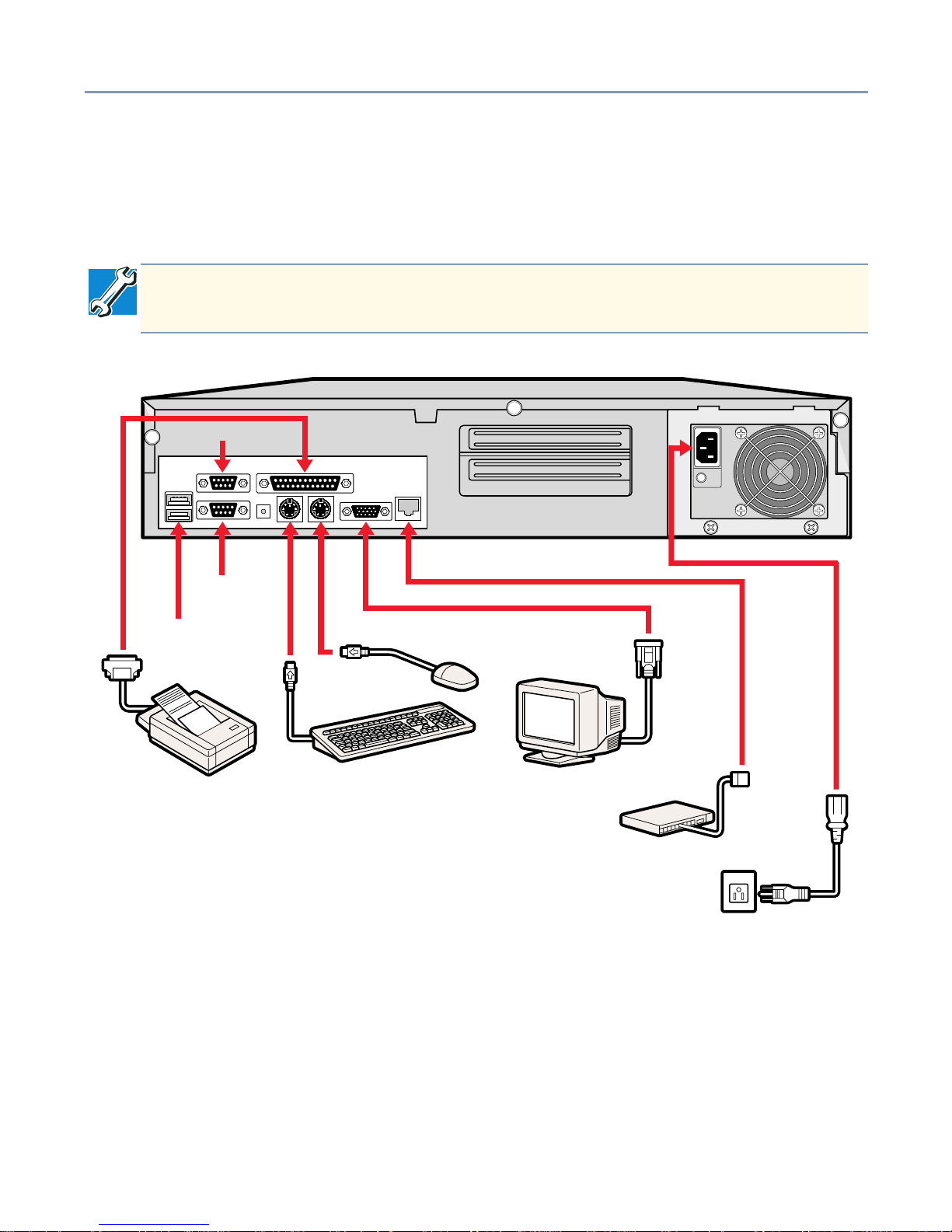
Rear Panel
Identifying the AC Power Connector and I/O Signal Ports
This section provides a description of the server’s AC power connector and I/O ports. It
also provides information on connecting peripheral devices to the server.
Rear panel connections
TECHNICAL NOTE: The output voltages from the I/O connectors on the back of the
server do not exceed 12V.
USB Connectors
COM 1
COM 2
Getting Started Inside the Server 29
Using USB-Compliant Devices
Keep in mind the following considerations
❖ A USB-compatible keyboard or mouse cannot be used with BIOS setup or the
Hardware Diagnostics Program.
❖ Windows NT 4.0 and Novell NetWare do not support the USB standard.
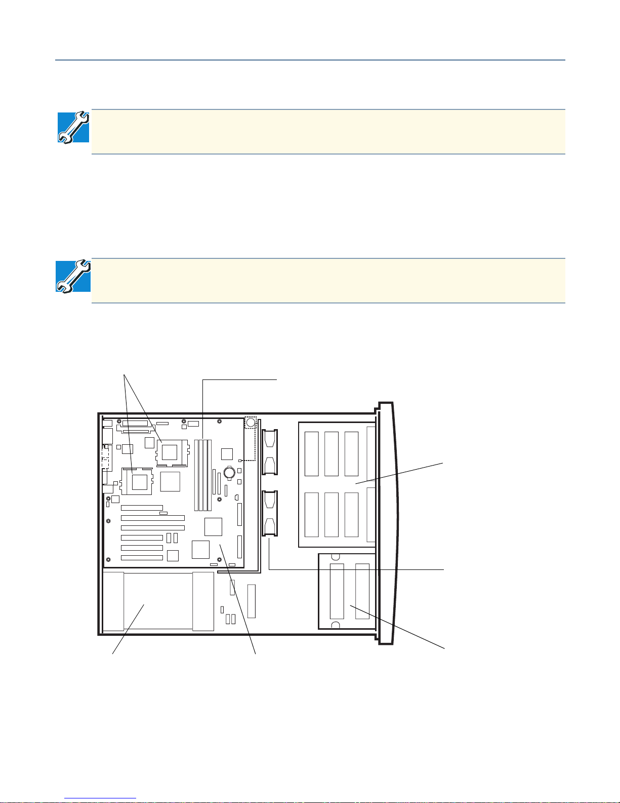
Inside the Server
Top View of major system components
TECHNICAL NOTE: Before connecting a USB-compatible device, check whether
the operating system installed on your server supports the USB standard.
TECHNICAL NOTE: The BIOS installed in the Magnia 3135R does not support PS/
2 emulation when using a USB keyboard.
CPU socket
CD/FDD bay
HDD bays
DIMM sockets
Cooling fan assembly
Motherboard
Power supply unit

Getting Started Inside the Server 30
Motherboard
The motherboard contains two CPU sockets, four DIMM sockets, and two PCI expansion
card slots on the riser board.
CPU Sockets
The Toshiba Magnia 3135R contains two CPU sockets. For instructions on installing and
removing a processor, see CPU Modules
on page 61.
Internal Battery
The lithium battery on the server board powers the real-time clock (RTC) for up to 5
years in the absence of power. When the battery starts to weaken, it loses voltage and
the server settings stored in CMOS RAM in the RTC (for example, the date and time)
may be wrong. For instructions on replacing the RTC battery, see Replacing the Internal
Battery on page 71.
Memory Bank
The memory bank contains four slots, supporting installation of up to four memory
modules. For system memory upgrade information, see Memory Modules
on page 56.
Expansion Slots
The Toshiba Magnia 3135R supports the addition of two PCI cards. Both PCI slots are
located on the riser card which has two full-length standard PCI connectors
CAUTION: Do not use any expansion slots on the server board
 Loading...