

Page 1

User’s Manual
TECRA M7
Page 2

Copyright
© 2006 by TOSHIBA Corporation. All rights reserved. Under the copyright
laws, this manual cannot be reproduced in any form without the prior
written permission of TOSHIBA. No patent liability is assumed, with respect
to the use of the information contained herein.
TOSHIBA TECRA M7 Portable Personal Computer User’s Manual
First edition June 2006
Copyright authority for music, movies, computer programs, data bases and
other intellectual property covered by copyright laws belongs to the author
or to the copyright owner. Copyrighted material can be reproduced only for
personal use or use within the home. Any other use beyond that stipulated
above (including conversion to digital format, alteration, transfer of copied
material and distribution on a network) without the permission of the
copyright owner is a violation of copyright or author’s rights and is subject
to civil damages or criminal action. Please comply with copyright laws in
making any reproduction from this manual.
Disclaimer
This manual has been validated and reviewed for accuracy. The instructions
and descriptions it contains are accurate for the TOSHIBA TECRA M7
Portable Personal Computer at the time of this manual’s production.
However, succeeding computers and manuals are subject to change
without notice. TOSHIBA assumes no liability for damages incurred directly
or indirectly from errors, omissions or discrepancies between the computer
and the manual.
Trademarks
IBM is a registered trademark and IBM PC is a trademark of International
Business Machines Corporation.
Intel, Intel SpeedStep, Intel Core, Celeron and Centrino are trademarks or
registered trademarks of Intel Corporation.
Windows and Microsoft are registered trademarks of Microsoft Corporation.
Photo CD is a trademark of Eastman Kodak.
Sonic RecordNow! is a registered trademark of Sonic Solutions.
Bluetooth is a trademark owned by its proprietor and used by TOSHIBA
under license.
Memory Stick and i.LINK are trademark and registered trademark of Sony
Corporation.
InterVideo and WinDVD are registered trademarks of InterVideo Inc.
Other trademarks and registered trademarks not listed above may be used
in this manual.
ii User’s Manual
Page 3

EU Declaration of Conformity
CE compliance
This product is labelled with the CE Mark in accordance with the related
European Directives, notably Electromagnetic Compatibility Directive
89/336/EEC for the notebook and the electronic accessories including the
supplied power adapter, the Radio Equipment and Telecommunications
Terminal Equipment Directive 1999/5/EC in case of implemented
telecommunication accessories and the Low Voltage Directive 73/23/EEC
for the supplied power adapter.
CE Marking is the responsibility of TOSHIBA EUROPE GmbH,
Hammfelddamm 8, 41460 Neuss, Germany, phone +49-(0)-2131-158-01.
For a copy of the related CE Declaration of Conformity please refer to the
following website: http://epps.toshiba-teg.com
This product and the supplied accessories are designed to observe the
related EMC (Electromagnetic Compatibility) and safety standards.
However, Toshiba cannot guarantee that this product still observes these
EMC standards if accessories or cables not manufactured / distributed by
Toshiba are connected or implemented. To avoid in general EMC problems,
the following advice should be observed:
■ Only CE marked accessories should be connected / implemented
■ Only best shielded cables should be connected
Working environment
This product was designed to fulfill the EMC (Electromagnetic Compatibility)
requirements for “residential, commercial and light industry environments”.
The following environment is not approved:
■ Industrial Environments (e.g. environments where a mains voltage of
380V three-phase is being used).
In the following environments the use of this product can be restricted:
■ Medical Environments: This product is not certified as a medical
product according to the Medical Product Directive 93/42/EEC, but can
be used in office areas where the use is not restricted. Please disable
the wireless LAN or Bluetooth hardware in such areas as long this
feature is not official supported by the operator of the related medical
facility.
■ Vehicle Environments: Please read the operator’s manual of the vehicle
manufacturer for further restrictions of use.
■ Aircraft Environments: Please follow the advices of the flight personnel
regarding restrictions of use.
User’s Manual iii
Page 4

Any consequences resulting from the use of this product in working
environments that are not approved or the use is restricted are not the
responsibility of Toshiba Corporation. The consequences of the use of this
product in those working environments may be:
■ Interference with other devices or machines in the nearby surrounding
area
■ Malfunction of, or data loss from, this product caused by disturbances
generated by other devices or machines in the nearby surrounding area
Furthermore, for general safety reasons, the use of this product in
environments with explosive atmospheres is not permitted.
Modem warning notice
Conformity Statement
The equipment has been approved to [Commission Decision “CTR21”] for
pan-European single terminal connection to the Public Switched Telephone
Network (PSTN).
However, due to differences between the individual PSTNs provided in
different countries/regions the approval does not, of itself, give an
unconditional assurance of successful operation on every PSTN network
termination point.
In the event of problems, you should contact your equipment supplier in the
first instance.
Network Compatibility Statement
This product is designed to work with, and is compatible with the following
networks. It has been tested to and found to conform with the additional
requirements conditional in EG 201 121.
Germany ATAAB AN005,AN006,AN007,AN009,AN010
Greece ATAAB AN005,AN006 and GR01,02,03,04
Portugal ATAAB AN001,005,006,007,011 and
Spain ATAAB AN005,007,012, and ES01
Switzerland ATAAB AN002
All other countries/regions ATAAB AN003,004
Specific switch settings or software setup are required for each network,
please refer to the relevant sections of the user guide for more details.
The hookflash (timed break register recall) function is subject to separate
national type approvals. It has not been tested for conformity to national
type regulations, and no guarantee of successful operation of that specific
function on specific national networks can be given.
and DE03,04,05,08,09,12,14,17
P03,04,08,10
iv User’s Manual
Page 5

Following information is only for EU-member states:
The use of the symbol indicates that this product may not be treated as
household waste. By ensuring this product is disposed of correctly, you will
help prevent potential negative consequences for the environment and
human health, which could otherwise be caused by inappropriate waste
handling of this product. For more detailed information about recycling of
this product, please contact your local city office, your household waste
disposal service or the shop where you purchased the product.
Optical disc drive safety instructions
Be sure to check the international precautions at the end of this section.
TEAC
DVD-ROM drive DV-28E
■ The DVD-ROM drive DV-28E employs a laser system. To ensure
proper use of this product, please read this instruction manual carefully
and retain for future reference. Should the unit ever require
maintenance, contact an authorized service location.
■ Use of controls, adjustments or the performance of procedures other
than those specified may result in hazardous radiation exposure.
■ To prevent direct exposure to the laser beam, do not try to open the
enclosure.
User’s Manual v
Page 6

Panasonic Communications
DVD-ROM & CD-R/RW drive UJDA770
■ The DVD-ROM & CD-R/RW drive UJDA770 employs a laser system.
To ensure proper use of this product, please read this instruction
manual carefully and retain for future reference. Should the unit ever
require maintenance, contact an authorized service location.
■ Use of controls, adjustments or the performance of procedures other
than those specified may result in hazardous radiation exposure.
■ To prevent direct exposure to the laser beam, do not try to open the
enclosure.
vi User’s Manual
Page 7

TEAC
DVD-ROM & CD-R/RW drive DW-224E
■ The DVD-ROM & CD-R/RW drive DW-224E employs a laser system.
To ensure proper use of this product, please read this instruction
manual carefully and retain for future reference. Should the unit ever
require maintenance, contact an authorized service location.
■ Use of controls, adjustments or the performance of procedures other
than those specified may result in hazardous radiation exposure.
■ To prevent direct exposure to the laser beam, do not try to open the
enclosure.
User’s Manual vii
Page 8
Panasonic Communications
DVD Super Multi with Double Layer Recording UJ-841
■ The DVD Super Multi drive with Double Layer Recording model
employs a laser system. To ensure proper use of this product, please
read this instruction manual carefully and retain for future reference.
Should the unit ever require maintenance, contact an authorized
service location.
■ Use of controls, adjustments or the performance of procedures other
than those specified may result in hazardous radiation exposure.
■ To prevent direct exposure to the laser beam, do not try to open the
enclosure.
viii User’s Manual
Page 9

Pioneer
DVD Super Multi with Double Layer Recording DVR-K16
■ The DVD Super Multi drive with Double Layer Recording model
employs a laser system. To ensure proper use of this product, please
read this instruction manual carefully and retain for future reference.
Should the unit ever require maintenance, contact an authorized
service location.
■ Use of controls, adjustments or the performance of procedures other
than those specified may result in hazardous radiation exposure.
■ To prevent direct exposure to the laser beam, do not try to open the
enclosure.
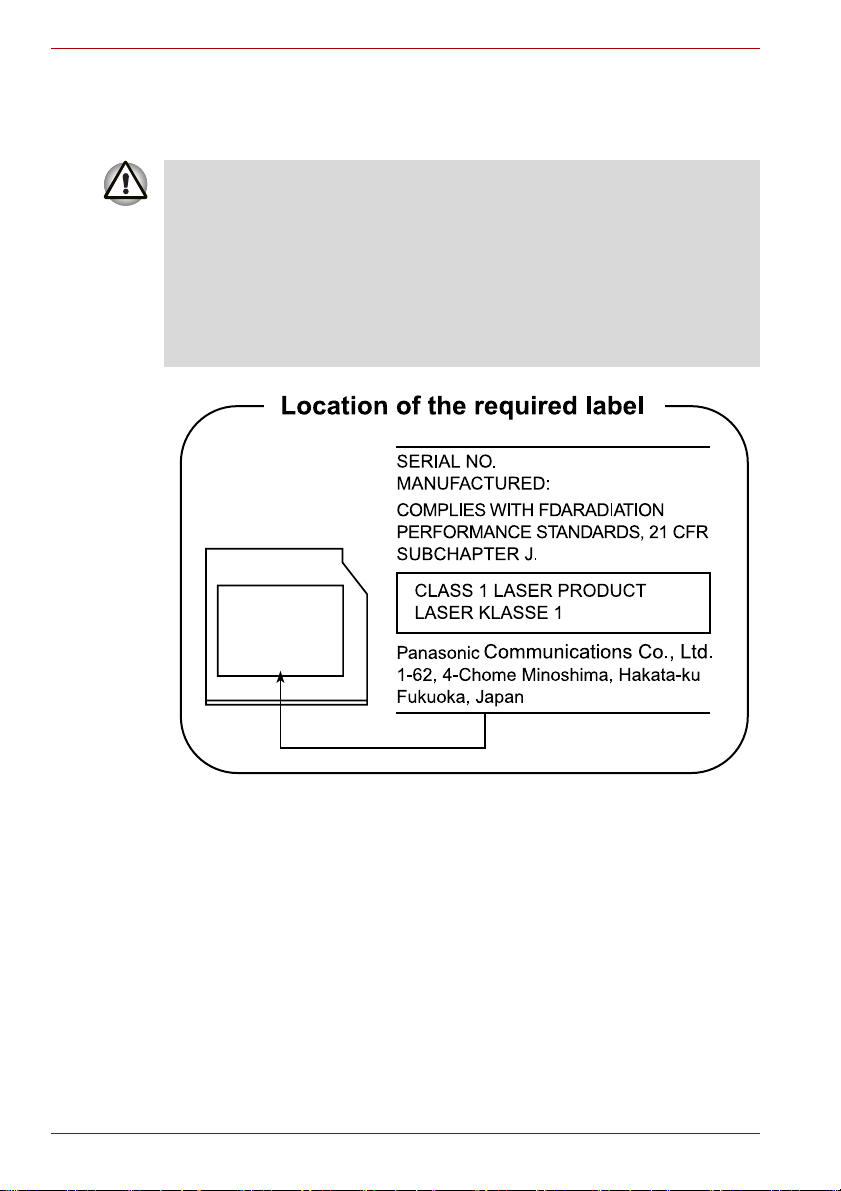
MFD.
SER.NO.
CERTIFICATION
THIS PRODUCT COMPLIES WITH 21
CFR 1040. 10 AND 1040. 11 EXCEPT
FOR DEVIATIONS PURSUANT TO
LASER NOTICE NO.50.
PIONEER CORPORATION.
4-1, MEGURO 1-CHOME, MEGUROKU, TOKYO, 153-8654, JAPAN
User’s Manual ix
Page 10

International precautions
CAUTION: This appliance contains a
laser system and is classified as a
“CLASS 1 LASER PRODUCT.” To use
this model properly, read the instruction
manual carefully and keep this manual
for your future reference. In case of any
trouble with this model, please contact
your nearest “AUTHORIZED service
station.” To prevent direct exposure to the
laser beam, do not try to open the
enclosure.
VORSICHT: Dieses Gerät enthält ein
Laser-System und ist als
“LASERSCHUTZKLASSE 1 PRODUKT”
klassifiziert. Für den richtigen Gebrauch
dieses Modells lesen Sie bitte die
Bedienungsanleitung sorgfältig durch
und bewahren diese bitte als Referenz
auf. Falls Probleme mit diesem Modell
auftreten, benachrichtigen Sie bitte die
nächste “autorisierte Service-Vertretung”.
Um einen direkten Kontakt mit dem
Laserstrahl zu vermeiden darf das Gerät
nicht geöffnet werden.
ADVARSEL: Denne mærking er anbragt
udvendigt på apparatet og indikerer, at
apparatet arbejder med laserstråler af
klasse 1, hviket betyder, at der anvendes
laserstrlier af svageste klasse, og at man
ikke på apparatets yderside kan bilve
udsat for utilladellg kraftig stråling.
APPARATET BOR KUN ÅBNES AF
FAGFOLK MED SÆRLIGT KENDSKAB
TIL APPARATER MED
LASERSTRÅLER!
Indvendigt i apparatet er anbragt den her
gengivne advarselsmækning, som
advarer imod at foretage sådanne
indgreb i apparatet, at man kan komme til
at udsatte sig for laserstråling.
x User’s Manual
Page 11

OBS! Apparaten innehåller
laserkomponent som avger laserstråining
överstigande gränsen för laserklass 1.
VAROITUS. Suojakoteloa si saa avata.
Laite sisältää laserdiodin, joka lähetää
näkymätöntä silmilie vaarallista
lasersäteilyä.
CAUTION: USE OF CONTROLS OR
ADJUSTMENTS OR PERFORMANCE
OF PROCEDURES OTHER THAN
THOSE SPECIFIED IN THE OWNER’S
MANUAL MAY RESULT IN
HAZARDOUS RADIATION EXPOSURE.
VORSICHT: DIE VERWENDUNG VON
ANDEREN STEUERUNGEN ODER
EINSTELLUNGEN ODER DAS
DURCHFÜHREN VON ANDEREN
VORGÄNGEN ALS IN DER
BEDIENUNGSANLEITUNG
BESCHRIEBEN KÖNNEN
GEFÄHRLICHE
STRAHLENEXPOSITIONEN ZUR
FOLGE HABEN.
User’s Manual xi
Page 12

xii User’s Manual
Page 13

Table of Contents
Preface
General Precautions
Chapter 1 Getting Started
Equipment checklist. . . . . . . . . . . . . . . . . . . . . . . . . . . . . . . . . . . . . . . 1-1
Getting Started . . . . . . . . . . . . . . . . . . . . . . . . . . . . . . . . . . . . . . . . . . . 1-3
Operating the computer in Tablet mode. . . . . . . . . . . . . . . . . . . . . . . 1-4
Connecting the AC adaptor . . . . . . . . . . . . . . . . . . . . . . . . . . . . . . . . . 1-6
Opening the display . . . . . . . . . . . . . . . . . . . . . . . . . . . . . . . . . . . . . . . 1-8
Turning on the power . . . . . . . . . . . . . . . . . . . . . . . . . . . . . . . . . . . . . . 1-8
Starting up for the first time . . . . . . . . . . . . . . . . . . . . . . . . . . . . . . . . 1-9
Turning off the power . . . . . . . . . . . . . . . . . . . . . . . . . . . . . . . . . . . . . . 1-9
Restarting the computer . . . . . . . . . . . . . . . . . . . . . . . . . . . . . . . . . . 1-13
Restoring the preinstalled software . . . . . . . . . . . . . . . . . . . . . . . . . 1-13
Chapter 2 The Grand Tour
Front with the display closed . . . . . . . . . . . . . . . . . . . . . . . . . . . . . . . 2-1
Left side. . . . . . . . . . . . . . . . . . . . . . . . . . . . . . . . . . . . . . . . . . . . . . . . . 2-3
Right side . . . . . . . . . . . . . . . . . . . . . . . . . . . . . . . . . . . . . . . . . . . . . . . 2-4
Back side. . . . . . . . . . . . . . . . . . . . . . . . . . . . . . . . . . . . . . . . . . . . . . . . 2-5
Underside . . . . . . . . . . . . . . . . . . . . . . . . . . . . . . . . . . . . . . . . . . . . . . . 2-7
Front with the display open. . . . . . . . . . . . . . . . . . . . . . . . . . . . . . . . . 2-8
Operation buttons . . . . . . . . . . . . . . . . . . . . . . . . . . . . . . . . . . . . . . . 2-11
System indicators. . . . . . . . . . . . . . . . . . . . . . . . . . . . . . . . . . . . . . . . 2-11
Keyboard indicators. . . . . . . . . . . . . . . . . . . . . . . . . . . . . . . . . . . . . . 2-12
Optical disc drives . . . . . . . . . . . . . . . . . . . . . . . . . . . . . . . . . . . . . . . 2-13
AC adaptor . . . . . . . . . . . . . . . . . . . . . . . . . . . . . . . . . . . . . . . . . . . . . 2-16
Chapter 3 Features, Utilities and Options
Features. . . . . . . . . . . . . . . . . . . . . . . . . . . . . . . . . . . . . . . . . . . . . . . . . 3-1
Special features . . . . . . . . . . . . . . . . . . . . . . . . . . . . . . . . . . . . . . . . . . 3-5
Utilities. . . . . . . . . . . . . . . . . . . . . . . . . . . . . . . . . . . . . . . . . . . . . . . . . . 3-7
Optional devices. . . . . . . . . . . . . . . . . . . . . . . . . . . . . . . . . . . . . . . . . 3-11
PC card . . . . . . . . . . . . . . . . . . . . . . . . . . . . . . . . . . . . . . . . . . . . . . . . 3-12
Bridge media slot . . . . . . . . . . . . . . . . . . . . . . . . . . . . . . . . . . . . . . . . 3-14
Memory expansion . . . . . . . . . . . . . . . . . . . . . . . . . . . . . . . . . . . . . . . 3-21
Battery Pack . . . . . . . . . . . . . . . . . . . . . . . . . . . . . . . . . . . . . . . . . . . . 3-26
User’s Manual xiii
Page 14

Universal AC Adaptor . . . . . . . . . . . . . . . . . . . . . . . . . . . . . . . . . . . . .3-27
Slice Expansion Battery . . . . . . . . . . . . . . . . . . . . . . . . . . . . . . . . . . .3-27
Battery Charger . . . . . . . . . . . . . . . . . . . . . . . . . . . . . . . . . . . . . . . . . .3-28
USB FDD Kit . . . . . . . . . . . . . . . . . . . . . . . . . . . . . . . . . . . . . . . . . . . . .3-28
Tablet PC Pen . . . . . . . . . . . . . . . . . . . . . . . . . . . . . . . . . . . . . . . . . . . .3-30
Reserve Pen . . . . . . . . . . . . . . . . . . . . . . . . . . . . . . . . . . . . . . . . . . . . .3-30
External monitor. . . . . . . . . . . . . . . . . . . . . . . . . . . . . . . . . . . . . . . . . .3-30
TV. . . . . . . . . . . . . . . . . . . . . . . . . . . . . . . . . . . . . . . . . . . . . . . . . . . . . .3-31
Displaying movies on a TV or CRT. . . . . . . . . . . . . . . . . . . . . . . . . . .3-32
i.LINK (IEEE1394) . . . . . . . . . . . . . . . . . . . . . . . . . . . . . . . . . . . . . . . . .3-33
TOSHIBA Express Port Replicator . . . . . . . . . . . . . . . . . . . . . . . . . . .3-35
Bluetooth USB Adaptor . . . . . . . . . . . . . . . . . . . . . . . . . . . . . . . . . . . .3-36
Wireless Optical Mouse with Bluetooth Technology . . . . . . . . . . . .3-36
Wireless Stereo Headset with Bluetooth Technology. . . . . . . . . . . .3-36
Security lock. . . . . . . . . . . . . . . . . . . . . . . . . . . . . . . . . . . . . . . . . . . . .3-36
Options . . . . . . . . . . . . . . . . . . . . . . . . . . . . . . . . . . . . . . . . . . . . . . . . .3-37
Chapter 4 Operating Basics
Using the Touch Pad . . . . . . . . . . . . . . . . . . . . . . . . . . . . . . . . . . . . . . .4-1
Using the Tablet PC Pen and Reserve Pen . . . . . . . . . . . . . . . . . . . . .4-2
Changing to the Tablet mode . . . . . . . . . . . . . . . . . . . . . . . . . . . . . . . .4-7
Changing the screen orientation . . . . . . . . . . . . . . . . . . . . . . . . . . . .4-10
Using Accelerometer Utilities . . . . . . . . . . . . . . . . . . . . . . . . . . . . . . .4-12
Changing to the laptop mode . . . . . . . . . . . . . . . . . . . . . . . . . . . . . . .4-13
Using the Fingerprint Sensor . . . . . . . . . . . . . . . . . . . . . . . . . . . . . . .4-13
Using optical disc drives. . . . . . . . . . . . . . . . . . . . . . . . . . . . . . . . . . .4-20
Writing CDs on DVD-ROM&CD-R/RW drive . . . . . . . . . . . . . . . . . . . .4-24
Writing CD/DVDs on DVD Super Multi drive . . . . . . . . . . . . . . . . . . .4-26
Media care. . . . . . . . . . . . . . . . . . . . . . . . . . . . . . . . . . . . . . . . . . . . . . .4-32
Sound System . . . . . . . . . . . . . . . . . . . . . . . . . . . . . . . . . . . . . . . . . . .4-33
Modem. . . . . . . . . . . . . . . . . . . . . . . . . . . . . . . . . . . . . . . . . . . . . . . . . .4-34
Wireless communications . . . . . . . . . . . . . . . . . . . . . . . . . . . . . . . . . .4-37
LAN . . . . . . . . . . . . . . . . . . . . . . . . . . . . . . . . . . . . . . . . . . . . . . . . . . . .4-41
Cleaning the computer . . . . . . . . . . . . . . . . . . . . . . . . . . . . . . . . . . . .4-43
Moving the computer. . . . . . . . . . . . . . . . . . . . . . . . . . . . . . . . . . . . . .4-43
Using the Hard Disk Drive (HDD) Protection . . . . . . . . . . . . . . . . . . .4-44
Heat dispersal. . . . . . . . . . . . . . . . . . . . . . . . . . . . . . . . . . . . . . . . . . . .4-46
Chapter 5 The Keyboard
Typewriter keys . . . . . . . . . . . . . . . . . . . . . . . . . . . . . . . . . . . . . . . . . . .5-1
Function keys: F1 … F12. . . . . . . . . . . . . . . . . . . . . . . . . . . . . . . . . . . .5-2
Soft keys: Fn key combinations . . . . . . . . . . . . . . . . . . . . . . . . . . . . . .5-2
Hot keys . . . . . . . . . . . . . . . . . . . . . . . . . . . . . . . . . . . . . . . . . . . . . . . . .5-3
Windows special keys . . . . . . . . . . . . . . . . . . . . . . . . . . . . . . . . . . . . . .5-7
Keypad overlay. . . . . . . . . . . . . . . . . . . . . . . . . . . . . . . . . . . . . . . . . . . .5-7
Generating ASCII characters. . . . . . . . . . . . . . . . . . . . . . . . . . . . . . . . .5-9
xiv User’s Manual
Page 15

Chapter 6 Power and Power-Up Modes
Power conditions . . . . . . . . . . . . . . . . . . . . . . . . . . . . . . . . . . . . . . . . . 6-1
Power indicators. . . . . . . . . . . . . . . . . . . . . . . . . . . . . . . . . . . . . . . . . . 6-4
Battery types. . . . . . . . . . . . . . . . . . . . . . . . . . . . . . . . . . . . . . . . . . . . . 6-5
Care and use of the battery pack . . . . . . . . . . . . . . . . . . . . . . . . . . . . 6-7
Replacing the battery pack . . . . . . . . . . . . . . . . . . . . . . . . . . . . . . . . 6-11
TOSHIBA Password Utility. . . . . . . . . . . . . . . . . . . . . . . . . . . . . . . . . 6-13
Tablet mode. . . . . . . . . . . . . . . . . . . . . . . . . . . . . . . . . . . . . . . . . . . . . 6-17
Power-up modes. . . . . . . . . . . . . . . . . . . . . . . . . . . . . . . . . . . . . . . . . 6-17
Panel power on/off . . . . . . . . . . . . . . . . . . . . . . . . . . . . . . . . . . . . . . . 6-18
System Auto Off . . . . . . . . . . . . . . . . . . . . . . . . . . . . . . . . . . . . . . . . . 6-18
Chapter 7 HW Setup & BIOS Setup
Accessing HW Setup . . . . . . . . . . . . . . . . . . . . . . . . . . . . . . . . . . . . . . 7-1
HW Setup window . . . . . . . . . . . . . . . . . . . . . . . . . . . . . . . . . . . . . . . . 7-1
BIOS Setup Program . . . . . . . . . . . . . . . . . . . . . . . . . . . . . . . . . . . . . . 7-8
Chapter 8 Troubleshooting
Problem solving process. . . . . . . . . . . . . . . . . . . . . . . . . . . . . . . . . . . 8-1
Hardware and system checklist . . . . . . . . . . . . . . . . . . . . . . . . . . . . . 8-3
TOSHIBA support . . . . . . . . . . . . . . . . . . . . . . . . . . . . . . . . . . . . . . . . 8-23
Appendix A Specifications
Physical Dimensions . . . . . . . . . . . . . . . . . . . . . . . . . . . . . . . . . . . . . . A-1
Appendix B Display Controller and Modes
Display controller . . . . . . . . . . . . . . . . . . . . . . . . . . . . . . . . . . . . . . . . . B-1
Video mode . . . . . . . . . . . . . . . . . . . . . . . . . . . . . . . . . . . . . . . . . . . . . . B-1
PowerMizer . . . . . . . . . . . . . . . . . . . . . . . . . . . . . . . . . . . . . . . . . . . . . . B-2
Appendix C Wireless LAN
Card Specifications . . . . . . . . . . . . . . . . . . . . . . . . . . . . . . . . . . . . . . . C-1
Radio Characteristics. . . . . . . . . . . . . . . . . . . . . . . . . . . . . . . . . . . . . . C-2
Supported Frequency Sub-bands. . . . . . . . . . . . . . . . . . . . . . . . . . . . C-3
Appendix D Bluetooth wireless technology Interoperability
Bluetooth wireless technology and your Health . . . . . . . . . . . . . . . . D-3
Regulatory statements. . . . . . . . . . . . . . . . . . . . . . . . . . . . . . . . . . . . . D-3
Appendix E AC Power Cord and Connectors
Certification agencies . . . . . . . . . . . . . . . . . . . . . . . . . . . . . . . . . . . . . E-1
Appendix F TOSHIBA Anti-theft Protection Timer
Appendix G Legal Footnotes
Appendix H If your computer is stolen
Glossary
Index
User’s Manual xv
Page 16

xvi User’s Manual
Page 17

Preface
Congratulations on your purchase of the TECRA M7 computer. This
powerful notebook computer provides excellent expansion capability,
including multimedia devices, and it is designed to provide years of reliable,
high-performance computing.
This manual tells how to set up and begin using your TECRA M7 computer.
It also provides detailed information on configuring your computer, basic
operations and care, using optional devices and troubleshooting.
If you are a new user of computers or if you’re new to portable computing,
first read over the Getting Started and Features, Utilities and Options
chapters to familiarize yourself with the computer’s features, components
and accessory devices. Then read Getting Started for step-by-step
instructions on setting up your computer.
If you are an experienced computer user, please continue reading the
preface to learn how this manual is organized, then become acquainted
with this manual by browsing through its pages. Be sure to look over the
Special features section of the Introduction, to learn about features that are
uncommon or unique to the computer and carefully read HW Setup & BIOS
Setup.
If you are going to install PC cards or connect external devices such as a
monitor, be sure to read Chapter 3, Features, Utilities and Options.
Conventions
This manual uses the following formats to describe, identify, and highlight
terms and operating procedures.
Abbreviations
On first appearance, and whenever necessary for clarity, abbreviations are
enclosed in parentheses following their definition. For example: Read Only
Memory (ROM). Acronyms are also defined in the Glossary.
Icons
Icons identify ports, dials, and other parts of your computer. The indicator
panel also uses icons to identify the components it is providing information
on.
User’s Manual xvii
Page 18

Preface
Keys
Key operation
The keyboard keys are used in the text to describe many computer
operations. A distinctive typeface identifies the key top symbols as they
appear on the keyboard. For example, Enter identifies the Enter key.
Some operations require you to simultaneously use two or more keys. We
identify such operations by the key top symbols separated by a plus sign
(+). For example, Ctrl + C means you must hold down Ctrl and at the same
time press C. If three keys are used, hold down the first two and at the
same time press the third.
ABC
When procedures require an action such as
clicking an icon or entering text, the icon’s name
or the text you are to type in is represented in the
type face you see to the left.
Display
S ABC
Names of windows or icons or text generated by
the computer that appear on its display screen
are presented in the type face you see to the left.
Messages
Messages are used in this manual to bring important information to your
attention. Each type of message is identified as shown below.
Pay attention! A caution informs you that improper use of equipment or
failure to follow instructions may cause data loss or damage your
equipment.
Please read. A note is a hint or advice that helps you make best use of
your equipment.
Indicates a potentially hazardous situation, which could result in death or
serious injury, if you do not follow instructions.
xviii User’s Manual
Page 19

General Precautions
TOSHIBA computers are designed to optimize safety, minimize strain and
withstand the rigors of portability. However, certain precautions should be
observed to further reduce the risk of personal injury or damage to the
computer.
Be certain to read the general precautions below and to note the cautions
included in the text of the manual.
Creating a computer-friendly environment
Place the computer on a flat surface that is large enough for the computer
and any other items you are using, such as a printer.
Leave enough space around the computer and other equipment to provide
adequate ventilation. Otherwise, they may overheat.
To keep your computer in prime operating condition, protect your work area
from:
■ Dust, moisture, and direct sunlight.
■ Equipment that generates a strong electromagnetic field, such as
stereo speakers(other than speakers that are connected to the
computer) or speakerphones.
■ Rapid changes in temperature or humidity and sources of temperature
change such as air conditioner vents or heaters.
■ Extreme heat, cold, or humidity.
■ Liquids and corrosive chemicals.
Stress injury
Carefully read the Instruction Manual for Safety & Comfort. It contains
information on prevention of stress injuries to your hands and wrists than
can be caused by extensive keyboard use. Chapter 1, Getting Started, also
includes information on work space design, posture and lighting that can
help reduce physical stress.
User’s Manual xix
Page 20

General Precautions
Heat injury
■ Avoid prolonged physical contact with the computer. If the computer is
used for long periods, its surface can become very warm. While the
temperature will not feel hot to the touch, if you maintain physical
contact with the computer for a long time (if you rest the computer on
your lap, or if you keep your hands on the palm rest, for example) your
skin might suffer low-heat injury.
■ If the computer has been used for a long time, avoid direct contact with
the metal plate supporting the I/O ports. It can become hot.
■ The surface of the AC adaptor can become hot when in use. This
condition does not indicate a malfunction. If you need to transport the
AC adaptor, disconnect it and let it cool before moving it.
■ Do not lay the AC adaptor on a material that is sensitive to heat. The
material could be damaged.
Pressure or impact damage
Do not apply heavy pressure to the computer or subject it to strong impact.
Excessive pressure or impact can cause damage to computer components
or otherwise cause malfunctions.
PC card overheating
Some PC cards can become hot with prolonged use. Overheating of a PC
card can result in errors or instability in the PC card operation. Also be
careful when you remove a PC card that has been used for a long time.
Mobile phones
Use of mobile phones can interfere with the audio system. Computer
operation is not impaired but it is recommended that a distance of 30 cm be
maintained between the computer and a mobile phone in use.
Instruction Manual for Safety & Comfort
All important information on the safe and proper use of this computer is
described in the enclosed Instruction Manual for Safety & Comfort. Be sure
to read it before using the computer.
xx User’s Manual
Page 21

Getting Started
This chapter provides an equipment checklist, and basic information to start
using your computer.
Some of the features described in this manual may not function properly if
you use an operating system that was not preinstalled by TOSHIBA.
Equipment checklist
Carefully unpack your computer. Save the box and packing materials for
future use.
Hardware
Check to make sure you have all the following items:
■ TECRA M7 Portable Personal Computer
■ AC adaptor and power cord (2-pin plug or 3-pin plug)
■ USB floppy disk drive (Provided with some models)
■ Slice Expansion Battery (Provided with some models)
■ Tablet PC Pen
■ Reserve Pen (Provided with some models)
Chapter 1
■ The Tablet PC Pen is included in the accessory tray of the product
when purchased together with spare pen tips and a tip removal tool.
■ For some models, a Reserve Pen is also included in the accessory tray
of the product when purchased.
User’s Manual 1-1
Page 22

Getting Started
Documentation
Software
■ TECRA M7 Portable Personal Computer User’s Manual
■ TECRA M7 Quickstart
■ Microsoft Windows XP Tablet PC Edition Getting Started manual
■ Instruction Manual for Safety & Comfort
■ Warranty information
If any of the items are missing or damaged, contact your dealer
immediately.
Microsoft® Windows XP Tablet PC Edition
■ The following software is preinstalled:
■ Microsoft
■ Microsoft Internet Explorer
■ TOSHIBA Utilities
■ TOSHIBA SD Memory Boot Utility
■ DVD Video Player
■ RecordNow! Basic for TOSHIBA
■ DLA for TOSHIBA
■ Recovery Disc Creator
■ TOSHIBA TouchPad On/Off Utility
■ TOSHIBA Power Saver
■ TOSHIBA Mobile Extension
■ TOSHIBA Assist
■ TOSHIBA ConfigFree
■ TOSHIBA Zooming Utility
■ TOSHIBA PC Diagnostic Tool
■ TOSHIBA Controls
■ TOSHIBA Mic Effect
■ TOSHIBA Password Utility
■ TOSHIBA Rotation Utility
■ TOSHIBA Accelerometer Utilities
■ TOSHIBA Tablet Access Code Logon Utility
■ Fingerprint utility
■ TOSHIBA Hotkey Utility for Display Devices
■ TOSHIBA Display Device Change Utility
■ TOSHIBA SD Memory Card Format
■ CD/DVD Drive Acoustic Silencer
■ TOSHIBA Security Assist
®
Windows XP Tablet PC Edition
1-2 User’s Manual
Page 23

■ TOSHIBA HDD Protection
■ DVD-RAM Driver Software
■ Bluetooth Stack for Windows by Toshiba*
■ Infineon Trusted Platform Module*
(* provided with some models)
■ Online manual
■ Product Recovery Media
Getting Started
All users should be sure to read the section Starting up for the first time.
Be sure to read the enclosed Instruction Manual for Safety & Comfort for
information on the safe and proper use of this computer. It is intended to
help you be more comfortable and productive while using a notebook
computer. By following the recommendations in it you may reduce your
chance of developing a painful or disabling injury to your hand, arms,
shoulders or neck.
This section provides basic information to start using your computer. It
covers the following topics:
■ Connecting the AC adaptor
■ Opening the display
■ Turning on the power
■ Starting up for the first time
■ Turning off the power
■ Restarting the computer
Getting Started
■ Use a virus-check program and make sure it is updated regularly.
■ Never format storage media without checking its content. Formatting
destroys all stored data.
■ It is a good idea to periodically back up the internal hard disk or other
main storage device to external media. General storage media is not
durable or stable over long periods of time and under certain conditions
may result in data loss.
■ Before you install a device or application, save any data in memory to
the hard disk drive or other storage media. Failure to do so may result
in the loss of data.
User’s Manual 1-3
Page 24

Getting Started
Operating the computer in Tablet mode
The TOSHIBA TECRA M7 computer can be used in two ways, as an
ordinary laptop PC and as a Tablet PC. You can use the computer as
Tablet PC, operated with the supplied Tablet PC Pen, by turning the LCD
display panel through 180 degrees and closing it. This manual calls the
use as an ordinary laptop PC “laptop mode”, and the use as a Tablet PC
“Tablet mode”. Refer to Changing to the Tablet mode section in Chapter 4,
Operating Basics for details on changing the mode.
When operating the computer in tablet mode, follow the instructions below.
Operating the computer in tablet mode
■ Hold the computer firmly on your forearm. Do not block the vent.
■ Remove the AC adaptor from the computer when using it in tablet mode
held in your forearm.
■ Do not use the computer while walking or driving a car.
■ Change to laptop mode and turn off the computer before carrying it. Do
not carry the computer with power on or in stand by state. Do not carry
the computer while the disk activity LED is glowing.
■ Do not expose the computer to rapid temperature changes (such as
would be the case if you brought the PC from a cold environment into a
warm room). When rapid temperature changes are unavoidable, leave
the computer for around two hours before turning it on to prevent the
formation of condensation.
■ Remove all external peripheral devices and their connection cables
from the computer before carrying.
■ Do not drop the computer or apply excessive impact to it. Do not leave
the computer in a car or similar environment where it is exposed to
direct sunlight.
■ Do not put the computer in a bag when it is in tablet mode.
1-4 User’s Manual
Page 25

Getting Started
■ The display panel works as a touch sensitive digitizer screen. However,
the outer edges of the screen may be less sensitive. Please keep the
Tablet PC Pen inside the display area when you use it near the edges of
the display panel. The position of the pen may not be recognized if you
move the Tablet PC Pen too fast towards the outer edge. Please be
sure to slide the Tablet PC Pen slowly in areas near the edges of the
screen.
Use the Tablet PC Pen in the areas enclosed by the dotted line as
shown in the following figure.
Use area of a Tablet PC Pen
Do not block the vent of the computer when holding it. If you continue to
expose your skin to the hot air expelled from the vent for a long time, your
skin might suffer low temperature injury.
User’s Manual 1-5
Page 26

Getting Started
Connecting the AC adaptor
Attach the AC adaptor when you need to charge the battery or you want to
operate from AC power. It is also the fastest way to get started, because
the battery pack will need to be charged before you can operate from
battery power.
The AC adaptor can be connected to any power source supplying from
100 to 240 volts and 50 or 60 hertz. For details on using the AC adaptor to
charge the battery pack, refer to Chapter 6, Power and Power-Up Modes.
■ Always use the TOSHIBA AC adaptor that was provided with your PC
and the TOSHIBA Battery Charger (that may have been provided with
your PC), or use AC adaptors and battery chargers specified by
TOSHIBA to avoid any risk of fire or other damage to the PC. Use of an
incompatible AC adaptor or Battery Charger could cause fire or
damage to the PC possibly resulting in serious injury. TOSHIBA
assumes no liability for any damage caused by use of an incompatible
adaptor or Battery Charger.
■ Never plug the AC adaptor or Battery Charger into a power source that
does not correspond to both the voltage and the frequency specified on
the regulatory label of the unit. Failure to do so could result in a fire or
electric shock, possibly resulting in serious injury.
■ Always use or purchase power cables that comply with the legal
voltage and frequency specifications and requirements in the country of
use. Failure to do so could result in a fire or electric shock, possibly
resulting in serious injury.
■ The supplied power cord conforms to safety rules and regulations in
the region the product is bought and should not be used outside this
region. For use in other regions, please buy power cords that conform
to safety rules and regulations in the particular region.
■ Do not use a 3-pin to 2-pin conversion plug.
■ When you connect the AC adaptor to the computer, always follow the
steps in the exact order as described in the User’s Manual. Connecting
the power cable to a live electrical outlet should be the last step
otherwise the adaptor DC output plug could hold an electrical change
and cause an electrical shock or minor bodily injury when touched. As
a general safety precaution, avoid touching any metal parts.
■ Never place your PC or AC adaptor on a wooden surface, furniture, or
any other surface that could be marred by exposure to heat since the
PC base and AC adaptor’s surface increase in temperature during
normal use.
■ Always place your PC or AC adaptor on a flat and hard surface that is
resistant to heat damage.
Refer to the enclosed Instruction Manual for Safety & Comfort for detailed
precautions and handling instructions.
1-6 User’s Manual
Page 27
Getting Started
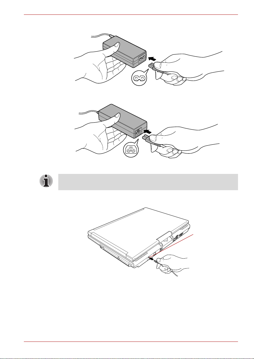
1. Connect the power cord to the AC adaptor.
Connecting the power cord to the AC adaptor (2-pin plug)
Connecting the power cord to the AC adaptor (3-pin plug)
Depending on the model, a 2-pin plug or 3-pin plug set of the above may
be bundled.
2. Connect the AC adaptor’s DC output plug to the DC IN 15V jack on the
back of the computer.
DC IN 15V jack
Connecting the adaptor to the computer
3. Plug the power cord into a live wall outlet. The Battery and DC IN
indicators on the front of the computer should glow.
User’s Manual 1-7
Page 28
Getting Started
Opening the display
The computer’s LCD display panel can be opened in a wide range of
angles for optimal viewing.
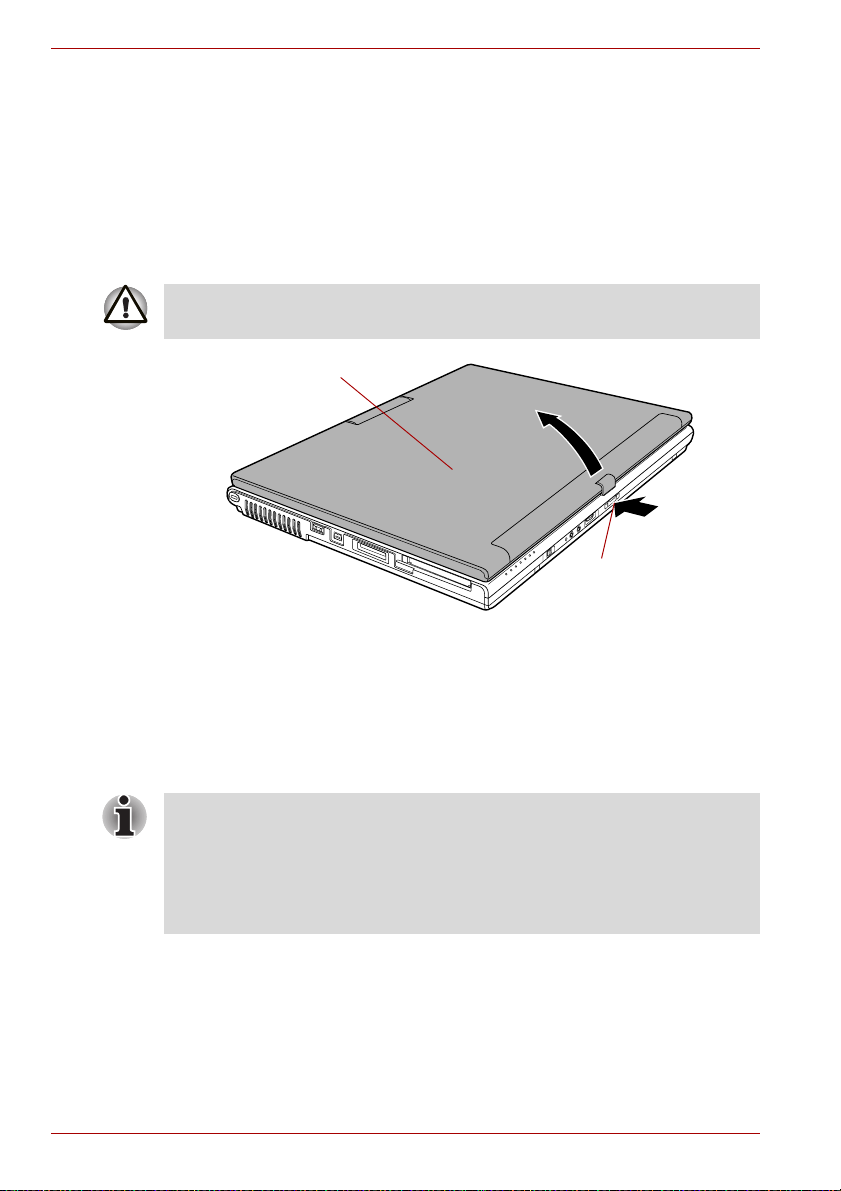
1. Push the display latch on the front of the computer to unlatch the
display panel.
2. While holding down the palm rest with one hand so that the main body
is not raised, lift the panel slowly. Adjust the angle of the panel to
provide optimal clarity.
Use reasonable care when opening and closing the LCD display panel.
Opening it vigorously or slamming it shut could damage the computer.
LCD display panel
Display latch
Opening the LCD display panel
Turning on the power
This section describes how to turn on the power.
The Power button LED indicates the status. Refer to the Power indicators
section in Chapter 6, Power and Power-Up Modes.
■ After you turn on the power for the first time, do not turn it off until you
have set up the operating system. Refer to the section Starting up for
the first time.
■ If the USB floppy disk drive is connected, make sure it is empty. If a
floppy disk is in the drive, press the eject button and remove the floppy
disk.
1. Open the computer’s LCD display panel.
1-8 User’s Manual
Page 29
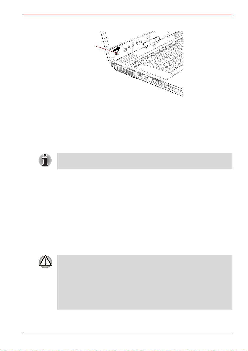
2. Slide and hold the computer’s power button.
Power button
Turning on the power
Starting up for the first time
When you first turn on the power, the computer’s initial screen is the
Microsoft Windows XP Startup Screen Logo. Follow the on-screen
directions for each screen. During setup, you can click the Back button to
return to the previous screen.
Be sure to read the Windows End User License Agreement display
carefully.
Getting Started
Turning off the power
The power can be turned off in one of the following modes: Shut down
(Boot), Hibernation or Standby Mode.
Shut Down mode (Boot mode)
When you turn off the power in Shut Down mode no data is saved and the
computer will boot to the operating system’s main screen.
1. If you have entered data, save it to the hard disk or to a storage media.
2. Make sure all disk (disc) activity has stopped, then remove the
CD/DVDs or floppy disk.
■ Make sure the hard disk drive indicator is off. If you turn off the power
while a disk (disc) is being accessed, you can lose data or damage the
disk.
■ Never turn off the power while an application is running. Doing so could
cause loss of data.
■ Never turn off the power, disconnect an external storage device or
remove storage media during data read/write. Doing so can cause data
loss.
3. Click start then click Turn Off Computer. From the Turn Off
Computer menu select Tur n O f f .
User’s Manual 1-9
Page 30

Getting Started
Standby Mode
4. Turn off the power to any peripheral devices.
Do not turn the computer or devices back on immediately. Wait a moment
to let all capacitors fully discharge.
If you have to interrupt your work, you can turn off the power without exiting
from your software. Data is maintained in the computer’s main memory.
When you turn on the power again, you can continue working right where
you left off.
■ When the AC adaptor is connected, the computer will go into Standby
Mode according to the settings in the TOSHIBA Power Saver.
■ To restore operation from Standby Mode, slide the power button or
press any key. The latter action only works on the internal keyboard if
the Wake-up on Keyboard option is enabled in HW Setup.
■ If the computer automatically enters Standby Mode while a network
application is active, the application might not be restored when the
computer wakes up from Standby.
■ To prevent the computer from automatically entering Standby Mode,
disable Standby in TOSHIBA Power Saver. That action, however, will
nullify the computer’s Energy Star compliance.
■ Before entering Standby Mode, be sure to save your data.
■ Do not install or remove a memory module while the computer is in
Standby Mode. The computer or the module could be damaged.
■ Do not remove the battery pack while the computer is in Standby Mode
(unless the computer is connected to an AC power source). Data in
memory will be lost.
■ If you carry the computer on board an aircraft or into a hospital, be sure
to shut down the computer in Hibernation Mode or in shutdown mode
to avoid radio signal interference.
Benefits of standby
The standby feature provides the following benefits:
■ Restores the previous working environment more rapidly than does
hibernation.
■ Saves power by shutting down the system when the computer receives
no input or hardware access for the duration set by the System Standby
feature.
■ You can use the panel power off feature.
1-10 User’s Manual
Page 31

Getting Started
Executing standby
You can also enable Standby by pressing Fn + F3. Refer to Chapter 5, The
Keyboard, for details.
You can enter Standby Mode in one of three ways:
1. Click start, click Turn Off Computer and click Stand By.
2. Close the computer’s LCD display panel. This feature must be enabled.
Refer to the Setup Actions tab in TOSHIBA Power Saver located within
the Control application (open Performance and Maintenance and then
open TOSHIBA Power Saver).
3. Slide the power button. This feature must be enabled. Refer to the
Setup Actions tab in TOSHIBA Power Saver described in the Control
application.
Open Performance and Maintenance and open TOSHIBA Power
Saver.
When you turn the power back on, you can continue where you left when
you shut down the computer.
■ When the computer is shut down in Standby Mode, the power indicator
will blink orange.
■ If you are operating the computer on battery power, you can lengthen
the operating time by shutting down in Hibernation Mode. Standby
Mode consumes more power.
Standby limitations
Standby will not function under the following conditions:
■ Power is turned back on immediately after shutting down.
■ Memory circuits are exposed to static electricity or electrical noise.
Hibernation Mode
The Hibernation Mode feature saves the contents of memory to the hard
disk when the computer is turned off. The next time the computer is turned
on, the previous state is restored. The Hibernation Mode feature does not
save the status of any peripheral devices.
■ Save your data. While entering Hibernation Mode, the computer saves
the contents of memory to the hard disk drive. However, for safety
sake, it is best to save your data manually.
■ Data will be lost if you remove the battery or disconnect the AC adaptor
before the save is completed. Wait for the HDD indicator to go out.
■ Do not install or remove a memory module while the computer is in
Hibernation Mode. Data will be lost.
User’s Manual 1-11
Page 32

Getting Started
Benefits of Hibernation Mode
The Hibernation Mode feature provides the following benefits:
■ Saves data to the hard disk when the computer automatically shuts
down because of a low battery.
For the computer to shut down in Hibernation Mode, this feature must be
enabled in two places: the Hibernate tab in Power Options and Setup
Actions tab in TOSHIBA Power Saver.
If you do not configure this feature, the computer will shut down in Standby
Mode - if battery power becomes depleted, data saved in Standby Mode
will be lost.
■ You can return to your previous working environment immediately when
you turn on the computer.
■ Saves power by shutting down the system when the computer receives
no input or hardware access for the duration set by the System
hibernate feature.
■ You can use the panel power off feature.
Starting Hibernation Mode
You can also enable Hibernation Mode by pressing Fn + F4. Refer to
Chapter 5, The Keyboard, for details.
To enter Hibernation Mode, follow the steps below.
1. Click start.
2. Select Turn Off Computer.
3. Open the Turn Off Computer dialog box.
4. Click Hibernate.
Automatic Hibernation
The computer will enter Hibernate mode automatically when you slide the
power button or close the lid. First, however, make the appropriate settings
according to the steps below.
1. Click start and open the Control Panel.
2. Open Performance and Maintenance and open Power Options.
3. Select the Hibernate tab in the Power Options Properties, select
the Enable hibernation check box and click the Apply button.
4. Open TOSHIBA Power Saver.
5. Select the Setup Actions tab.
6. Enable the desired Hibernation settings for When I press the power
button and When I close the lid.
7. Click the OK button.
1-12 User’s Manual
Page 33

Data save in Hibernation Mode
When you turn off the power in Hibernation Mode, the computer takes a
moment to save current memory data to the hard disk. During this time, the
HDD indicator will light.
After you turn off the computer, and the content of memory has been saved
to the hard disk, turn off the power to any peripheral devices.
Do not turn the computer or devices back on immediately. Wait a moment
to let all capacitors fully discharge.
Restarting the computer
Certain conditions require that you reset the system. For example, if:
■ You change certain computer settings.
■ An error occurs and the computer does not respond to your keyboard
commands.
■ There are three ways to reset the computer system:
1. Click start then click Turn off computer. From the Turn off
computer menu select Restart.
2. Press Ctrl + Alt + Del to display the Windows Task Manager, then
select Shut Down and Restart.
3. Slide the power button and hold it down for five seconds. Wait 10 to
15 seconds, then turn the power on again by sliding the power button.
Getting Started
Restoring the preinstalled software
If preinstalled files are damaged, use the Product Recovery Media to
restore them. To restore the operating system and all preinstalled software,
follow the steps below.
When you reinstall the Windows operating system, the hard disk will be
reformatted and all data will be lost.
1. Load the Product Recovery Media in the optional optical disc drive and
turn off the computer’s power.
2. Hold down the F12 key and turn on the power. When In Touch with
Tomorrow TOSHIBA appears, release the F12 key.
3. Use the left or right cursor key to select the optical disc drive in the
Boot Devices menu. For details, refer to the Boot Priority section in
Chapter 7, HW Setup & BIOS Setup.
4. Follow the on-screen instructions.
5. If your computer came with additional software installed, this software
can not be recovered from the Product Recovery Media. Re-install
these applications (e.g. Works Suite, DVD Player, Games, etc.)
separately from other media.
User’s Manual 1-13
Page 34

Getting Started
Restoring TOSHIBA utilities and drivers
If Windows is working properly, individual drivers or applications can be
separately restored. The TOSHIBA Tools & Utilities folder (C:\TOOLSCD)
contains drivers and applications, which are included with your computer
system. If your system drivers or applications have become damaged in
some way, you can reinstall most of the components from this folder.
Create a copy of this folder to an external media for more convenience.
1-14 User’s Manual
Page 35

The Grand Tour
This Chapter identifies the various components of your computer. Become
familiar with each component before you operate the computer.
Legal Footnote (Non-applicable Icons)*1
For more information on the Legal Footnote regarding Non-applicable
Icons, please refer to the Legal Footnotes section in Appendix G. Click
the *1.
Front with the display closed
The following figure the computer’s front with its LCD display panel in the
closed position.
System
indicators
Microphone
Headphone jack
Chapter 2
Volume control
Wireless communication
switch
Front of the computer with LCD display panel closed
System indicators These LEDs let you monitor the status of various
User’s Manual 2-1
Microphone jack
computer functions. Refer to the System
indicators section for details.
Display latch
Page 36

The Grand Tour
Wireless
communication
switch
Slide this switch to the left to turn off Wireless
LAN and Bluetooth functions. Slide it to the right
to turn on the functions.
All models are provided with a Wireless
Communication switch although only some
models are equipped with both Wireless LAN
and Bluetooth functions.
■ Turn Wi-Fi® and Bluetooth functionalities off when near a person who
may have a cardiac pacemaker implant or other medical electric
device. Radio waves may affect pacemaker or medical device
operation, possibly resulting in serious injury. Follow the instruction of
your medical device when using any Wi-Fi® or Bluetooth functionality.
®
■ Always turn off Wi-Fi
or Bluetooth functionality if the PC is near
automatic control equipment or appliances such as automatic doors or
fire detectors. Radio waves can cause malfunction of such equipment,
possibly resulting in serious injury.
■ Do not use the Wi-Fi® or Bluetooth functionalities near a microwave
oven or in areas subject to radio interference or magnetic fields.
Interference from a microwave oven or other source can disrupt Wi-Fi®
or Bluetooth operation.
Microphone The built-in microphone let you record sound into
your applications. Refer to the Sound System
section in Chapter 4, Operating Basics.
Microphone jack A 3.5 mm mini microphone jack enables
connection of a three-conductor mini jack for
monaural microphone input.
Headphone jack A 3.5 mm mini headphone jack enables
connection of stereo headphones.
Volume control Use this dial to adjust the volume of the stereo
speakers and the stereo headphones.
Move the Volume control to the right to increase
the volume and to the left to decrease the volume.
Press the Volume control to Mute the sound.
Press the Volume control again to turn Mute off.
The mute icon will be displayed when the Volume
control is pressed. The same function can be
performed by pressing the Fn + Esc keys. Refer
to the Hot keys section in Chapter 5 for details on
the Fn + Esc keys.
Display latch This latch secures the LCD panel in its closed
position. Push the latch to open the display.
2-2 User’s Manual
Page 37

Left side
The following figure shows the computer’s left side.
Cooling vents
Universal Serial bus (USB
2.0) port
Bridge media slot
The Grand Tour
PC card eject
button
Security lock slot
i.LINK (IEEE1394) port
The left side of the computer
PC card slot
Security lock slot A security cable attaches to this slot. The
optional security cable anchors your computer to
a desk or other large object to deter theft.
Cooling vents Cooling vents help CPU keep from overheating.
Do not block the cooling vents. Keep foreign metal objects, such as
screws, staples and paper clips, out of the cooling vents. Foreign metal
objects can create a short circuit, which can cause damage and fire,
possibly resulting in serious injury.
Universal Serial Bus
(USB 2.0) port
The Universal Serial Bus port is on the left side.
The port comply with the USB 2.0 standard.
Keep foreign metal objects, such as screws, staples and paper clips, out of
the USB connectors. Foreign metal objects can create a short circuit,
which can cause damage and fire, possibly resulting in serious injury.
Operation of all functions of all USB devices has not been confirmed.
Some functions might not execute properly.
i.LINK (IEEE1394)
port
This port allows you to connect an external
device, such as a digital video camera for highspeed data transfer.
Bridge media slot This slot lets you insert an SD card, Memory
Stick (Pro), xD picture card, MultiMediaCard or
SDIO card device. Refer to Chapter 3, Features,
Utilities and Options.
User’s Manual 2-3
Page 38

The Grand Tour
Keep foreign metal objects, such as screws, staples and paper clips, out of
the Bridge Media Slot. Foreign metal objects can create a short circuit,
which can cause damage and fire, possibly resulting in serious injury.
PC card slot The PC card slot can accommodate a Type II
PC card eject button This button is used to remove a PC card from the
Keep foreign metal objects, such as screws, staples and paper clips, out of
the PC Card slot. Foreign metal objects can create a short circuit, which
can cause damage and fire, possibly resulting in serious injury.
Right side
The following figure shows the computer’s right side.
Tablet PC Pen
card. The slot supports 16-bit PC cards and
CardBus PC cards.
PC card slot.
Tablet PC Pen slot
Universal Serial bus
(USB 2.0) port
Optical disc drive
The right side of the computer
Tablet PC Pen slot The Tablet PC Pen slot provides storage for the
Tablet PC Pen.
Tablet PC Pen The Tablet PC Pen is stored within the right side
of the computer and enables direct data entry
through the display screen. Refer to the Using
the Tablet PC Pen and Reserve Pen section in
Chapter 4, Operating Basics.
Optical disc drive The computer is configured with a DVD-ROM
drive, a DVD-ROM&CD-R/RW drive or a DVD
Super Multi drive.
Universal Serial Bus
(USB 2.0) port
2-4 User’s Manual
The Universal Serial Bus port is on the right side.
Refer to Left side section, for details.
Page 39

Back side
The following figure shows the computer’s back side.
Modem jack
LAN active indicator
(orange)
LAN jack
The Grand Tour
Link indicator
(green)
DC IN 15V jack
S-Video out port
The back side of the computer
Universal Serial bus
(USB 2.0) ports
External monitor
port
DC IN 15V jack The AC adaptor connects to this jack. Use only
the model of AC adaptor that comes with the
computer. Using the wrong adaptor can damage
your computer.
Modem jack The modem jack lets you use a modular cable to
connect the modem directly to a telephone line.
■ Connection to any communication line other than an analog phone line
could cause a PC system failure.
■ Connect the built-in modem only to ordinary analog phone lines.
■ Never connect the built-in modem to a digital line (ISDN).
■ Never connect the built-in modem to the digital connector on a
public telephone or to a digital private branch exchange (PBX).
■ Never connect the built-in modem to a key telephone system for
residences or offices.
■ Never operate your PC on AC power during a thunderstorm. If you see
lightning or hear thunder, immediately turn off the PC. An electric surge
caused by the storm, may result in a system failure, loss of data or
hardware damage.
S-Video out port Plug an S-Video cable into this jack for S-Video.
The S-Video cable carries video signal.
Data output depends on the type of device
connected to the S-Video cable.
User’s Manual 2-5
Page 40

The Grand Tour
LAN jack This jack lets you connect to a LAN. The adaptor
has built-in support for Ethernet LAN (10
megabits per second, 10BASE-T), Fast Ethernet
LAN (100 megabits per second, 100BASE-TX)
and Gigabit Ethernet LAN (1000 megabits per
second, 1000BASE-T). Gigabit Ethernet LAN is
supported with some models. The LAN has two
indicators. Refer to Chapter 4, Operating Basics,
for details.
■ Do not connect any cable other than a LAN cable to the LAN jack. It
could cause damage or malfunction.
■ Do not connect the LAN cable to a power supply. It could cause
damage or malfunction.
Link indicator
(green)
LAN active indicator
(orange)
Universal Serial Bus
(USB 2.0) ports
External monitor
port
This indicator glows green when the computer is
connected to a LAN and the LAN is functioning
properly.
This indicator glows orange when data is being
exchanged between the computer and the LAN.
Two Universal Serial Bus ports are on the back
side. Refer to Left side section, for details.
This external monitor port lets you connect an
external video display. Analog VGA port supports
VESA DDC2B compatible functions.
2-6 User’s Manual
Page 41

Underside
The following figure shows the underside of the computer. Make sure the
display is closed before turning over your computer.
The Grand Tour
Battery release
latch
Battery lock
Reserve Pen
The underside of the computer
Notches
Battery pack
Docking port
Notches Notches on the computer engage hooks on the
TOSHIBA Express Port Replicator to ensure a
secure connection.
Docking port This port enables connection of an optional
TOSHIBA Express Port Replicator and a Slice
Expansion Battery described in Chapter 3,
Features, Utilities and Options.
Keep foreign objects out of the docking port. A pin or similar object can
damage the computer’s circuitry. A plastic shutter protects the connector.
Battery pack The battery pack powers the computer when the
AC adaptor is not connected. For detailed
information on the battery pack, refer to
Chapter 6, Power and Power-Up Modes.
Battery lock Slide the battery lock to release the battery pack
for removal.
User’s Manual 2-7
Page 42

The Grand Tour
Battery release latch Slide and hold this latch to release the battery
pack for removal.
For detailed information on removing the battery
pack, refer to Chapter 6, Power and Power-Up
Modes.
Reserve Pen The Reserve Pen is contained in the recess on
the underside of the battery pack and enables
data entry directly through display screen in
addition to the main Tablet PC Pen. Refer to the
Using the Tablet PC Pen and Reserve Pen
section in Chapter 4, Operating Basics.
Front with the display open
This section shows the computer with the LCD display panel open. Refer to
the appropriate illustration for details. To open the display, push the display
latch on the front of the LCD display panel and lift up. Position the LCD
display panel at a comfortable viewing angle.
Windows
Security tablet
button
ESC/Rotation
button
Cross Function
Power button
Stereo speaker
Display screen
button
(Left)
Operation buttons
TOSHIBA Assist button
TOSHIBA Presentation button
Display hinge
Fingerprint Sensor
Stereo speaker (Right)
LCD Sensor switch
(Not shown)
Keyboard
Touch Pad
control buttons
Touch Pad
The front of the computer with the LCD panel open
Display hinge The display hinge holds the LCD display panel at
easy-to-view angles.
2-8 User’s Manual
Page 43

The Grand Tour
Display screen The LCD screen displays high-contrast text and
graphics. Refer to Display Controller and Modes
section in Appendix B.
When the computer operates on the AC adaptor
the LCD screen’s image will be somewhat
brighter than when it operates on battery power.
The lower brightness level is intended to save
battery power.
Stereo speakers The speakers emit sound generated by your
software as well as audio alarms, such as low
battery condition, generated by the system.
Touch Pad A Touch Pad located in the center of the palm
rest is used to control the on-screen pointer and
scrolling of windows. Refer to the Using the
Touch Pad section in Chapter 4, Operating
Basics.
Touch Pad control
buttons
Control buttons below the Touch Pad let you
select menu items or manipulate text and
graphics designated by the on-screen pointer.
Keyboard
84 keys or 85 keys, compatible with IBM®
enhanced keyboard, embedded numeric overlay,
dedicated cursor control, and keys.
Refer to Chapter 5, The Keyboard, for details.
Power button Slide the power button to turn the computer’s
power on and off.
Cross Function
button
This button functions the same as the Enter key
when tapped, or shows the menu screen when
pressed for more than a second.
ESC/Rotation button This button functions the same as the ESC key
when tapped, or changes the orientation of the
screen when pressed for more than a second.
Windows Security
tablet button
User’s Manual 2-9
This button functions the same as the Ctrl + Alt +
Del keys to show Windows Task Manager.
Page 44

The Grand Tour
TOSHIBA Assist
button
Press this button to launch the TOSHIBA Assist
utility (default) or some other predefined
application.
When the computer is switched off, or is in
standby or hibernation mode, press this button to
start the computer and launch the assigned
application.
You can specify the function of the TOSHIBA
Assist button in the TOSHIBA Controls
properties.
TOSHIBA
Presentation button
Press this button to display the same image on
both internal and external monitors, or to use
multi-monitor display (Windows XP Only).
The default setting is “Presentation (Same Image
1024 × 768)” - this means the same image will be
displayed on both internal and external monitors
with a resolution of 1024 × 768 pixels.
When using the “Presentation (Different Image)”
setting, you can use the internal and external
monitors in wide screen mode (Windows XP
only).
Pressing this button again changes to single
display mode on the internal monitor only.
You can specify the function of the TOSHIBA
Presentation button in the TOSHIBA Controls
properties.
Fingerprint Sensor
This sensor enables you to enroll and recognize a
fingerprint.
For detailed information on Fingerprint Sensor,
refer to Chapter 4, Using the Fingerprint Sensor.
LCD Sensor switch This switch senses when the computer’s LCD
display panel is closed or opened and activates
the Panel Power Off/On feature. When you close
the LCD display panel the computer enters
Hibernation Mode and shuts down. When you
open the computer’s LCD display panel the
computer starts in Hibernation Mode. Use the
TOSHIBA Power Saver to enable or disable this
feature. The default is “enabled”.
Refer to the TOSHIBA Power Saver and Panel
Power Off/On items in Chapter 3, Special
features, for details on settings.
Do not put a magnetic object close to the switch. The computer will
automatically enter Hibernation Mode and shut down even if the Panel
Power Off feature is disabled.
2-10 User’s Manual
Page 45

Operation buttons
This section describes the operation buttons.
Please do not press the buttons too strenuously.
Application 1 This button allows you to run applications and
Application 2
System indicators
LEDs above icons, light when various computer operations are in progress.
The Grand Tour
access utilities. An application and a function to
assign can be configured individually.When the
computer is switched off, or is in standby or
hibernation mode, press this button to start the
computer and launch the assigned
application.This button settings can be
changed only by administrator.
System indicators
Bridge Media The Bridge Media indicator glows green when
the computer is accessing the Bridge media slot.
DC IN The DC IN indicator glows green when DC power
is supplied from the AC power adaptor. If the
adaptor’s output voltage is abnormal or if the
power supply malfunctions, this indicator flashes
orange.
Power The Power indicator glows green when the
computer is on. If you select Stand by from the
Turn off computer window, this indicator
flashing (one second on, two seconds off) while
the computer Standby mode.
Battery The Battery indicator shows the condition of the
battery’s charge: Green indicates full charge,
orange indicates battery charging and flashing
orange indicates a low battery charge. Refer to
Chapter 6, Power and Power-Up Modes.
User’s Manual 2-11
Page 46

The Grand Tour
2nd battery The 2nd battery indicator shows the condition of
HDD The HDD indicator glows green when the
Wireless
communication
Keyboard indicators
The figures below show the positions of the keypad overlay indicators and
the Caps Lock indicator.
When the Arrow mode indicator glows the keypad overlay lets you control
the cursor.
When the Numeric mode indicator glows the keypad overlay lets you enter
numbers.
When the Caps Lock indicator glows the keyboard is in all-caps mode.
the charge of a Slice Expansion Battery. Green
means fully charged and orange means being
charged. Refer to Chapter 6, Power and Power-
Up Modes.
computer is accessing the built-in Hard Disk
Drive.
The Wireless communication indicator glows
when the Bluetooth and wireless LAN functions
are turned on.
All models are provided with a Wireless
Communication switch although only some
models are equipped with both Wireless LAN
and Bluetooth functions.
Caps Lock indicator
Caps Lock indicator
Caps Lock This indicator glows green when the alphabet
keys are locked in uppercase.
2-12 User’s Manual
Page 47

The Grand Tour
Arrow mode
indicator
Numeric mode
indicator
Keypad overlay indicators
Arrow mode When the Arrow mode indicator lights green,
you can use the keypad overlay (gray labeled
keys) as cursor keys. Refer to the Keypad
overlay section in Chapter 5, The Keyboard.
Numeric mode You can use the keypad overlay (gray labeled
keys) for numeric input when the Numeric mode
indicator lights green. Refer to the Keypad
overlay section in Chapter 5, The Keyboard.
Optical disc drives
The computer is installed with either a DVD-ROM, DVD-ROM&CD-R/RW
or a DVD Super Multi drive. An ATAPI interface controller is used for
CD/DVD-ROM operation. When the computer is accessing a CD/DVD, an
indicator on the drive glows.
For information on loading and unloading discs refer to the Using optical
disc drives section in Chapter 4, Operating Basics.
Region codes for DVD drives and media
DVD-ROM, DVD-ROM&CD-R/RW, DVD Super Multi drives and their
associated media are manufactured according to the specifications of six
marketing regions. When you purchase DVD-Video, make sure it matches
your drive, otherwise it will not play properly.
Code Region
1 Canada, United States
2 Japan, Europe, South Africa, Middle East
3 Southeast Asia, East Asia
4 Australia, New Zealand, Pacific Islands, Central America,
South America, Caribbean
User’s Manual 2-13
Page 48

The Grand Tour
Writable discs
CDs
DVDs
Formats
5 Russia, Indian Subcontinent, Africa, North Korea, Mongolia
6 China
This section describes the types of writable CD/DVD discs. Check the
specifications of your drive to see the types of discs it can write. Use
RecordNow! to write compact discs. Refer to Chapter 3, Features, Utilities
and Options.
■ CD-R discs can be written only once. The recorded data cannot be
erased or changed.
■ CD-RW discs including multi speed CD-RW discs, high-speed CD-RW
discs and ultra-speed CD-RW discs can be recorded more than once.
■ DVD-R and DVD+R discs can be written only once. The recorded data
cannot be erased or changed.
■ DVD-RW, DVD+RW and DVD-RAM discs can be recorded more than
once.
The drives support the following formats.
DVD-ROM drive
The drive supports the formats CD-ROM, DVD-ROM, DVD-Video, CD-DA,
CD-Text, Photo CD
CD-ROM XA Mode 2 (Form1, Form2), Enhanced CD (CD-EXTRA) and
Addressing Method 2.
TM
(single/multi-session), CD-ROM Mode 1, Mode 2,
DVD-ROM&CD-R/RW drive
The drive supports the formats in addition to the DVD-ROM drive, and
CD-R, CD-RW.
DVD Super Multi drive Double Layer
The drive supports the formats in addition to the DVD-ROM&CD-R/RW
drive, and DVD-R, DVD-RW, DVD+R, DVD+RW, DVD-RAM,
DVD-R DL (Format1), DVD+R DL.
Some types and formats of DVD-R DL and DVD+R DL discs may be
unreadable.
2-14 User’s Manual
Page 49

DVD-ROM drive
The full-size DVD-ROM drive module lets you run either 12 cm (4.72") or
8 cm (3.15") CD/DVDs without using an adaptor.
The read speed is slower at the center of a disc and faster at the outer
edge.
DVD read 8 speed (maximum)
CD read 24 speed (maximum)
DVD-ROM&CD-R/RW drive
The full-size DVD-ROM&CD-R/RW drive module lets you record data to
rewritable CDs as well as run either 12 cm (4.72") or 8 cm (3.15") CD/DVDs
without using an adaptor.
The read speed is slower at the center of a disc and faster at the outer
edge.
DVD read 8 speed (maximum)
CD read 24 speed (maximum)
CD-R write 24 speed (maximum)
CD-RW write 24 speed (maximum, Ultra-speed media)
DVD Super Multi drive Double Layer
The full-size DVD Super Multi drive module lets you record data to
rewritable CD/DVDs as well as run either 12 cm (4.72") or 8cm (3.15")
CD/DVDs without using an adaptor.
The Grand Tour
The read speed is slower at the center of a disc and faster at the outer
edge.
DVD read 8 speed (maximum)
DVD-R write 8 speed (maximum)
DVD-R DL write 2 speed (maximum)
DVD-RW write 4 speed (maximum)
DVD+R write 8 speed (maximum)
DVD+R DL write 2.4 speed (maximum)
DVD+RW write 4 speed (maximum)
DVD-RAM write 5 speed (maximum)
CD read 24 speed (maximum)
CD-R write 24 speed (maximum)
CD-RW write 10 speed (maximum, Ultra-speed media)
User’s Manual 2-15
Page 50

The Grand Tour
AC adaptor
The AC adaptor can automatically adjust to any voltage ranging from 100 to
240 volts and to a frequency of either 50 or 60 hertz, enabling you to use
this computer in almost any country/region. The adaptor converts AC
power to DC power and reduces the voltage supplied to this computer.
To recharge the battery, simply connect the AC adaptor to a power source
and the computer. Refer to Chapter 6, Power and Power-Up Modes for
details.
The AC adaptor (2-pin plug)
The AC adaptor (3-pin plug)
■ Depending on the model, a 2-pin plug or 3-pin plug set of the above
may be bundled.
■ Do not use a 3-pin to 2-pin conversion plug.
■ The supplied power cord conforms to safety rules and regulations in
the region the product is bought and should not be used outside this
region. For use in other regions, please buy power cords that conform
to safety rules and regulations in the particular region.
Always use the TOSHIBA AC adaptor that was provided with your PC and
the TOSHIBA Battery Charger (that may have been provided with your
PC), or use AC adaptors and battery chargers specified by TOSHIBA to
avoid any risk of fire or other damage to the PC. Use of an incompatible
AC adaptor or Battery Charger could cause fire or damage to the PC
possibly resulting in serious injury.
2-16 User’s Manual
Page 51

Chapter 3
Features, Utilities and Options
Features
The computer uses TOSHIBA’s advanced Large Scale Integration (LSI),
Complementary Metal-Oxide Semiconductor (CMOS) technology
extensively to provide compact size, minimum weight, low power usage,
and high reliability. This computer incorporates the following features and
benefits:
Processor
Built-in The computer is equipped with one of the
following Intel
■ Intel® Core™ Duo Processor, which
incorporates a 2MB level2 cache memory.
It also supports Enhanced Intel® SpeedStep®
Technology.
■ Intel® Core™ Solo Processor, which
incorporates a 2MB level2 cache memory.
It also supports Enhanced Intel
Technology.
■ Intel® Celeron® M Processor, which
incorporates a 1MB level2 cache memory.
User’s Manual 3-1
®
processors.
®
SpeedStep
®
Page 52

Features, Utilities and Options
■ Some models in the range are equipped with Intel® Centrino® Duo
Mobile Technology, which is based on three separate technologies of
®
Intel
Core™ Duo processor, Intel® PRO/Wireless Network
Connection, and Mobile Intel
■ In addition, some models in the range are equipped with carry Intel®
Centrino
technologies of Intel
Network Connection, and Mobile Intel
Legal Footnote (CPU)*2
For more information on the Legal Footnote regarding CPU, please refer to
the Legal Footnotes section in Appendix G. Click the *2.
Memory
Slots 256, 512 or 1,024 MB memory modules can be
®
945 Express Chipset Family.
®
Mobile Technology, which is based on three separate
®
Core™ Solo processor, Intel® PRO/Wireless
®
945 Express Chipset Family.
installed in the two memory slots for a maximum
of 2,048 MB system memory.
Video RAM There are two different types of graphics
controllers. The Video RAM specifications will
differ depending on the type of graphics
controller used in the computer.
■ Intel internal graphics system model: Up to
128MB of main system memory may be
allocated to this graphics controller for use as
Video memory.
■ nVIDIA Quadro NVS 110M model: This
graphics controller is equipped with 128MB of
on-board video RAM (memory), and may use
up to 128MB of main system memory as
additional video memory for a combined total
of up to 256MB of video memory.
Legal Footnote (Memory (Main System))*3
For more information on the Legal Footnote regarding Memory (Main
System), please refer to the Legal Footnotes section in Appendix G. Click
the *3.
Power
Battery pack The computer is powered by one rechargeable
lithium-ion battery pack.
Slice Expansion
Battery
This battery pack increases your computer’s
operating time when main battery pack is also
installed.
3-2 User’s Manual
Page 53

Features, Utilities and Options
Legal Footnote (Battery Life)*4
For more information on the Legal Footnote regarding Battery Life, please
refer to the Legal Footnotes section in Appendix G. Click the *4.
RTC battery The internal RTC battery backs up the Real Time
AC adaptor The AC adaptor provides power to the system
Clock (RTC) and calendar.
and recharges the batteries when they are low. It
comes with a detachable power cord which will
either have a 2-pin or 3-pin plug enclosure.
Because it is universal, it can receive a range of
AC voltage from 100 to 240 volts; however, the
output current varies among different models.
Using the wrong model can damage your
computer. Refer to the AC adaptor section in
Chapter 2, The Grand Tour.
Disks
Hard disk drive Available in three sizes.
■ 80.0 billion bytes (74.53 GB)
■ 100.0 billion bytes (93.16 GB)
■ 120.0 billion bytes (111.79 GB)
Part of the space in the hard disk drive is
reserved as administration space.
Legal Footnote (Hard Disk Drive (HDD) Capacity)*5
For more information on the Legal Footnote regarding Hard Disk Drive
(HDD) Capacity, please refer to the Legal Footnotes section in Appendix G.
Click the *5.
Optical disc drive
Drive This computer is equipped with one of the
User’s Manual 3-3
following drive types. The type of drive varies
according to model.
■ DVD-ROM drive
■ DVD-ROM & CD-R/RW drive
■ DVD Super Multi drive Double Layer drive
Page 54

Features, Utilities and Options
Display
The computer’s LCD display panel supports high-resolution video graphics.
The LCD screen can be set at a wide range of viewing angles for maximum
comfort and readability.
Built-in 14.1" TFT LCD screen, 16 million colors, with a
Legal Footnote (LCD)*6
For more information on the Legal Footnote regarding LCD, please refer to
the Legal Footnotes section in Appendix G. Click the *6.
resolution of 1440 horizontal × 900 vertical pixels
WXGA+.
Graphics controller The graphics controller maximizes display
performance. Refer to Display Controller and
Modes section in Appendix B for more
information.
Legal Footnote (Graphics Processor Unit (“GPU”))*7
For more information on the Legal Footnote regarding Graphics Processor
Unit (“GPU”), please refer to the Legal Footnotes section in Appendix G.
Click the *7.
Sound
Sound system The Windows sound system compatible sound
system provides output to internal speakers and
input from one internal microphone as well as
supports jacks for an external microphone and
headphones.
Communications
Modem An internal modem provides capability for data
and fax communication. It supports V.90 (V.92).
Refer to AC Power Cord and Connectors section
in Appendix E. The speed of data transfer and
fax depends on analog telephone line conditions.
It has a modem jack for connecting to a
telephone line. It is preinstalled as a standard
device in some markets. Both of V.90 and V.92
are supported only in USA, Canada, UK, France,
Germany and Australia. Only V.90 is available in
other regions.
3-4 User’s Manual
Page 55

Features, Utilities and Options
LAN The computer has built-in support for Ethernet
LAN (10 megabits per second, 10BASE-T), Fast
Ethernet LAN (100 megabits per second,
100BASE-TX) and Gigabit Ethernet LAN
(1000 megabits per second, 1000BASE-T).
Bluetooth Some computers in this series are equipped with
Bluetooth functions. Bluetooth wireless
technology eliminates the need for cables
between electronic devices such as computers
and printers. Bluetooth provides fast, reliable,
and secure wireless communication in a small
space.
Wireless LAN Some computers in this series are equipped with
Legal Footnote (Wireless LAN)*8
For more information on the Legal Footnote regarding Wireless LAN,
please refer to the Legal Footnotes section in Appendix G. Click the *8.
Special features
The following features are either unique to TOSHIBA computers or are
advanced features, which make the computer more convenient to use.
Hot keys Hot keys are specific key combinations that let
Display automatic
power off
a Wireless LAN card that is compatible with other
LAN systems based on Direct Sequence Spread
Spectrum/Orthogonal Frequency Division
Multiplexing radio technology that complies with
the IEEE 802.11 Standard (Revision A, B or G).
you quickly change the system configuration
directly from the keyboard without running a
system program.
This feature automatically cuts off power to the
computer’s LCD display panel when there is no
keyboard input for a specified time. Power is
restored when any key is pressed. You can
specify the time in the Monitor power off item of
the Basic Setup tab in TOSHIBA Power Saver.
HDD automatic
power off
User’s Manual 3-5
This feature automatically cuts off power to the
hard disk drive when it is not accessed for a
specified time. Power is restored when the hard
disk is accessed. You can specify the time in the
HDD power off item of the Basic Setup tab in
TOSHIBA Power Saver.
Page 56

Features, Utilities and Options
System automatic
Standby/Hibernation
This feature automatically shuts down the system
into either Standby Mode or Hibernation Mode
when there is no input or hardware access for a
specified time. You can specify the time and
select either the System Standby or System
Hibernation item of the Basic Setup tab in
TOSHIBA Power Saver.
Keypad overlay A ten-key pad is integrated into the keyboard.
Refer to the Keypad overlay section in Chapter 5,
The Keyboard, for instructions on using the
keypad overlay.
Power on password Two levels of password security, supervisor and
user, are available to prevent unauthorized
access to your computer.
Instant security A hot key function blanks the LCD screen and
disables the computer providing data security.
Intelligent power
supply
A microprocessor in the computer’s intelligent
power supply detects the battery’s charge and
calculates the remaining battery capacity. It also
protects electronic components from abnormal
conditions, such as voltage overload from an AC
adaptor. You can monitor remaining battery
capacity by using the Battery remaining item in
TOSHIBA Power Saver.
Battery save mode This feature lets you save battery power. You can
specify the Power Save Mode in the Profile item
in TOSHIBA Power Saver.
Panel power on/off This feature turns power to the computer off
when the computer’s LCD display panel is closed
and turns it back on when the computer’s LCD
display panel is opened. You can specify the
setting in the When I close the lid item of the
Setup Actions tab in TOSHIBA Power Saver.
Low battery
automatic
hibernation
When battery power is exhausted to the point that
computer operation cannot be continued, the
system automatically enters Hibernation and
shuts down. You can specify the setting in the
Setup Actions tab in TOSHIBA Power Saver.
Heat dispersal To protect from overheating, the CPU has an
internal temperature sensor. If the computer’s
internal temperature rises to a certain level, the
cooling fan is turned on or the processing speed
is lowered. Use the Cooling Method item of the
Basic Setup tab in TOSHIBA Power Saver.
3-6 User’s Manual
Page 57

Features, Utilities and Options
Optical Drive Power Use this to turn the power of the optical disc drive
on or off. Clicking on the Optical Drive Power icon
in the taskbar will turn the power to the optical
disc drive on or off. If the Optical Drive Power is
set to off, the disc tray will not open even if the
eject button is pushed - in this instance the power
to the drive can be turned on by again clicking the
Optical Drive Power icon.
TOSHIBA HDD
Protection
The TOSHIBA HDD Protection function does not guarantee that the hard
disk drive will not be damaged.
Hibernation This feature lets you turn off the power without
Standby If you have to interrupt your work, you can turn off
Using the acceleration sensor built in the
computer, the TOSHIBA HDD Protection function
detects vibrations and shocks, and automatically
moves the hard disk drive’s read/write head to a
safe position to reduce the risk of damage that
could be caused by head-to-disk contact. Refer to
the Using the Hard Disk Drive (HDD) Protection
section in Chapter 4, Operating Basics, for
details.
exiting from your software. The contents of main
memory are saved to the hard disk so that when
you next turn the power on again, you can
continue working right where you left off. Refer to
the Turning on the power section in Chapter 1,
Getting Started, for details.
the power without exiting from your software.
Data is maintained in the computer’s main
memory. When you turn on the power again, you
can continue working right where you left off.
Utilities
This section describes preinstalled utilities and tells how to start them. For
details on usage and operation, refer to each utility’s online manual, help
files or readme.txt files.
TOSHIBA Power
Saver
User’s Manual 3-7
To access this power savings management
program, click start, click Control Panel, click
Performance and Maintenance and click the
TOSHIBA Power Saver icon.
Page 58

Features, Utilities and Options
HW Setup This program lets you customize your hardware
settings according to the way you work with your
computer and the peripherals you use. To start
the utility, to access this utility, click start, click
Control Panel, click Printers and Other
Hardware and click the TOSHIBA HWSetup
icon.
TOSHIBA Controls This utility have a section to let you do the
following:
■ Buttons: Assign applications or functions to
the 4 buttons (TOSHIBA Assist, TOSHIBA
Presentation, Application1, Application2).
Fingerprint utility This product has a fingerprint utility installed for
the purpose of enrolling and recognizing
fingerprints. By enrolling the ID and password to
the fingerprint authentication device, it is no
longer necessary to input the password from the
keyboard. Fingerprint feature enables you to:
■ Logon to Windows and access a security-
enabled homepage through IE (Internet
Explorer).
■ Files and folders can be encrypted/decrypted
and third party access to them prevented.
■ Disable the password-protected screen-saver
when returning from power-saving (e.g.,
standby) mode.
■ Authentication of the User Password (and, if
applicable, the HDD(Hard Disk Drive)
Password) when booting up the computer
(Power-on Security).
■ Single Sign-on feature
DVD Video Player The DVD Video Player is used to play
DVD-Video. It has an on-screen interface and
functions. Click start, point to All Programs,
point to InterVideo WinDVD, then click
InterVideo WinDVD.
Bluetooth Stack for
Windows by Toshiba
This software enables communication between
remote Bluetooth devices.
Bluetooth cannot be used in models that do not have a Bluetooth module
installed.
3-8 User’s Manual
Page 59

Features, Utilities and Options
TOSHIBA SD
Memory Boot Utility
The TOSHIBA SD memory boot utility allows you
to create a bootable SD memory card to start the
system. You can access the TOSHIBA SD
Memory Boot Utility from the menu bar by
clicking start, point to All Programs, point to
TOSHIBA, point to Utilities and click SD
Memory Boot Utility.
TOSHIBA Zooming
Utility
This utility allows you to enlarge or reduce the
icon size on the desktop or the application
window.
RecordNow! Basic
for TOSHIBA
You can create CD/DVDs in several formats
including audio CDs that can be played on a
standard stereo CD player and data CD/DVDs to
store the files and folders on your hard disk drive.
This software can be used on models equipped
with a DVD-ROM & CD-R/RW drive or a DVD
Super Multi drive.
TOSHIBA Assist TOSHIBA Assist is a graphical user interface that
provides easy access to help and services. It is
the default function launched by the TOSHIBA
Assist button.
TOSHIBA PC
Diagnostic Tool
TOSHIBA PC Diagnostic Tool displays the basic
information on the computer’s configuration and
allows some of the built-in devices functionality to
be tested. To start TOSHIBA PC Diagnostic Tool,
click start, point to All Programs, point to
TOSHIBA, point to Utilities and click PC
Diagnostic Tool.
TOSHIBA Mobile
Extension
This utility enhances the function of your
computer when docking to an optional TOSHIBA
Express Port Replicator. To access the utility,
select TOSHIBA Mobile Extension from the
TOSHIBA Assist application.
TOSHIBA ConfigFree TOSHIBA ConfigFree is a suite of utilities to
allow easy control of communication devices and
network connections. TOSHIBA ConfigFree also
allows you to find communication problems and
create profiles for easy switching between
locations and communication networks. To start
ConfigFree, click start, point to All Programs,
point to TOSHIBA, point to Networking and click
ConfigFree.
TOSHIBA TouchPad
On/Off Utility
This utility allows you to disable/enable the Touch
Pad using the Fn + F9 Hot key.
User’s Manual 3-9
Page 60

Features, Utilities and Options
TOSHIBA Mic Effect The TOSHIBA Mic Effect utility provides you with
Echo Canceller and Microphone Array functions.
For more instructions for this software, click
start, point to All Programs, point to TOSHIBA,
point to Utilities and click TOSHIBA Mic Effect
Help.
TOSHIBA Password
Utility
TOSHIBA
Accessibility
This utility lets you set a password that restricts
access to the computer.
This utility lets you make the Fn key sticky, that
is, you can press it once, release it, and they
press an “F number” key. The Fn key remains
active until another key is pressed.
DLA for TOSHIBA DLA (Drive Letter Access) is the packet writing
software which provides the function to write files
and/or folders to DVD-RW, CD-RW and
DVD+RW discs via a drive letter like a floppy disk
or other removable disks.
TOSHIBA Hotkey
Utility for Display
Devices
This utility allows you to select the display device
as well as change the display resolution on that
device. Press the Fn + F5 Hot key to change the
active display device and press the Fn + Space
Hot key to change the display resolution.
TOSHIBA SD
Memory Card Format
The TOSHIBA SD Memory Card Format utility
allows you to format an SD memory card by the
SD standard format.
CD/DVD Drive
Acoustic Silencer
This utility allows you to configure the read speed
of the CD drive. You can either configure Normal
Mode, which operates the drive at its maximum
speed for quick data access, or Quiet Mode
which runs it at single speed for CD audio play
back and which lessens operational noise.
This utility has no effect when accessing DVD
media.
TOSHIBA
Accelerometer
Utilities
When TOSHIBA Accelerometer Utilities is
enabled, you can invoke the Start menu, switch
active windows or launch predefined applications
by shaking the computer vertically or horizontally,
or by tilting it.
You can start TOSHIBA Accelerometer Utilities
by clicking start, click All Programs, click
TOSHIBA, click Tablet P C and Setup for
TOSHIBA Accelerometer Utilities.
The Setting of TOSHIBA Accelerometer Utilities
screen appears.
3-10 User’s Manual
Page 61

Features, Utilities and Options
TOSHIBA Tablet
Access Code Logon
Utility
TOSHIBA Rotation
Utility
Optional devices
Optional devices can expand the computer’s capabilities and its versatility.
This section describes connection or installation of the following devices.
Cards/memory
■ PC card
■ Bridge media slot
■ SD card (SD memory card, SDIO card)
■ Memory Stick/Memory Stick Pro
■ xD picture card
■ MultiMediaCard
■ Memory expansion
If a Windows password has been set, you can
logon to the operating system by entering a
handwriting signature into the dialog box using
the Tablet PC Pen when prompted.
This utility controls the screen orientation setting
for both PC mode and Tablet mode.
You can set four types of orientation setting:
■ Primary landscape
■ Primary portrait
■ Secondary landscape
■ Secondary portrait
The default setting of PC mode is Primary
Landscape while that for Tablet mode is Primary
Portrait.
To start TOSHIBA Rotation Utility, Click start,
click All Programs, click TOSHIBA, click Tablet
PC and Rotation Utility.
Power devices
■ Battery Pack
■ Universal AC Adaptor
■ Slice Expansion Battery
■ Battery Charger
User’s Manual 3-11
Page 62

Features, Utilities and Options
Peripheral devices
■ USB FDD Kit
■ Tablet PC Pen
■ Reserve pen
■ External monitor
■ TV
■ i.LINK (IEEE1394)
■ TOSHIBA Express Port Replicator
■ Bluetooth USB Adaptor
■ Wireless Optical Mouse with Bluetooth Technology
■ Wireless Stereo Headset with Bluetooth Technology
Other
■ Security lock
PC card
The computer is equipped with a PC card slot that can accommodate a
Type II card. Any PC card that meets industry standards (manufactured by
TOSHIBA or other vendor) can be installed. The slot supports 16-bit PC
cards, including PC card 16’s multifunction card and CardBus PC cards.
CardBus supports the new standard of 32-bit PC cards. The bus provides
superior performance for the greater demands of multimedia data
transmission.
PC cards can sometimes become hot during PC operation. Before you
remove a PC card always wait for it to cool. You could get burned
removing a hot PC card.
Inserting a PC card
Windows hot-install feature lets you insert PC cards while the computer’s
power is on.
Do not insert a PC card while the computer is in Standby or Hibernation
Mode. Some cards might not work properly.
To insert a PC card, follow the steps below:
1. Insert a PC card in the PC card slot.
3-12 User’s Manual
Page 63

Features, Utilities and Options
2. Press gently to ensure a firm connection.
PC card slot
PC card
Inserting the PC card
3. After inserting the PC card, refer to the PC card’s documentation and
check the configuration in Windows to make sure it is appropriate for
your PC card.
Removing a PC card
To remove the PC card, follow the steps below.
1. Open the Safely Remove Hardware icon on the Task Bar.
2. Point to PC card and click.
3. Press the PC card eject button to extend it.
If the PC card is not inserted all the way, the eject button may not cause it
to pop out sufficiently to allows it to be grasped. Be sure to push the PC
card firmly into the computer and slide the eject button again.
4. Press the extended eject button to pop the card out slightly.
5. Grasp the PC card and draw it out.
PC card
PC card eject button
Removing the PC card
User’s Manual 3-13
Page 64

Features, Utilities and Options
Bridge media slot
This slot lets you insert SD memory card, SDIO card, Memory Stick (Pro),
xD picture card or MultiMediaCard.
This Bridge media slot supports the following cards.
■ SD card (SD memory card, SDIO card)
■ Memory Stick
■ Memory Stick PRO
■ xD picture card
■ MultiMediaCard
Precautions on using cards.
Please note that not all cards have been tested and verified to work
correctly. Therefore, it is not possible to guarantee that all cards will
operate properly.
Media care
Observe the following precautions when handling the card.
Card care
■ Do not twist or bend cards.
■ Do not expose cards to liquids or store in humid areas or lay media
close to containers of liquid.
■ Do not touch the metal part of a card or expose it to liquids or let it get
dirty.
■ After using card, return it to its case.
■ The card is designed so that it can be inserted only one way. Do not try
to force the card into the slot.
■ Do not leave a card partially inserted in the slot. Press the card until you
hear it click into place.
Memory card care
■ Set the write-protect switch to the lock position, if you do not want to
record data.
■ Memory cards are consumable items, so make sure you back up
important data.
■ Do not write to an SD card if the battery power is low. Low power could
affect writing accuracy.
■ Do not remove an SD card while read/write is in progress.
For more details on using memory cards, see manuals accompanying the
cards.
3-14 User’s Manual
Page 65

Features, Utilities and Options
SD card
Set the SD-card type SD memory cards and Bluetooth® SDIO cards in the
Bridge Media slot.
Keep foreign objects out of the Bridge media slot. Never allow metal
objects, such as screws, staples and paper clips, to enter the PC or
keyboard. Foreign metal objects can create a short circuit, which can
cause PC damage and fire, possibly resulting in serious injury.
Inserting an SD card
To insert an SD card, follow the steps below.
1. Insert an SD card in the Bridge media slot.
2. Press gently to ensure a firm connection.
Bridge media slot
SD card
Inserting an SD card
■ Make sure the SD card is oriented properly before you insert it.
■ Do not turn the computer off or switch to Standby Mode or Hibernate
Mode while files are being copied - doing so may cause data to be lost.
Removing an SD card
To remove an SD card, follow the steps below.
1. Open the Safely Remove Hardware icon on the Task Bar.
2. Point to SD card and click.
3. Push in the card and release it to pop the card out slightly.
User’s Manual 3-15
Page 66

Features, Utilities and Options
4. Grasp the card and remove it.
■ Make sure the Bridge media slot indicator is out before you remove
the SD card or turn off the computer’s power. If you remove the SD
card or turn off the power while the computer is accessing the SD card
you may lose data or damage the card.
■ Do not remove an SD card while the computer is in Standby or
Hibernation mode. The computer could become unstable or data in the
SD card could be lost.
SD memory card
SD cards let you easily transfer data from devices, such as digital cameras
and Personal Digital Assistants, that use SD card flash-memory. The cards
have a high level of security and copy protection features.
Bridge media slot
SD card
Removing an SD card
SD memory cards comply with SDMI (Secure Digital Music Initiative),
which is a technology adopted to prevent unlawful copy or playback of
digital music. For this reason, you cannot copy or playback protected
material on another computer or other device. You may not use the
reproduction of any copyrighted material except for your personal
enjoyment.
3-16 User’s Manual
Page 67

Features, Utilities and Options
Formatting an SD card
SD memory cards are sold already formatted in conformity to specific
standards. If you format the SD card again, be sure to format it with the
TOSHIBA SD Memory Card Format utility, not with the format commands
provided within Windows.
In order to run TOSHIBA SD Memory Card Format, click start, point to All
Programs, point to TOSHIBA, point to Utilities and click SD Memory
Card Format.
The TOSHIBA SD Memory Card Format utility does not format the
protected area of the SD memory card. Should you need to format all areas
of the memory card, including the protected area, you will need to obtain an
appropriate application that applies the copy protection system.
SDIO card
Add the Bluetooth® wireless communication function to a computer with the
SDIO card.
Memory Stick/Memory Stick Pro
The computer is equipped with a Bridge media slot that can accommodate
Memory Stick/Memory Stick Pro flash memory cards with various memory
capacities. Memory Stick let you easily transfer data from devices, such as
digital cameras and Personal Digital Assistants, that use Memory Stick
technology.
Keep foreign objects out of the Bridge media slot. Never allow metal
objects, such as screws, staples and paper clips, to enter the PC or
keyboard. Foreign metal objects can create a short circuit, which can
cause PC damage and fire, possibly resulting in serious injury.
■ The slot does not support Magic Gate functions.
■ Memory Stick Duo/PRO Duo and the Memory Stick adaptor are not
compatible with the Bridge media slot. Do not insert Memory Stick
Duo/PRO Duo into the slot. Data may be lost or damaged if you use
any card other than those supported.
Write protection
Memory Stick can be write protected to safeguard your data. To writeprotect a Memory Stick, slide the lock on the back of the Memory Stick to
the lock position.
User’s Manual 3-17
Page 68

Features, Utilities and Options
Inserting a Memory Stick
To insert a Memory Stick, follow the steps below.
1. Insert the Memory Stick into the Bridge media slot.
2. Press gently to ensure a firm connection.
Removing a Memory Stick
To remove a Memory Stick, follow the steps below.
1. Open the Safely Remove Hardware icon on the Task Bar.
2. Point to Memory Stick and click.
3. Push in the card and release it to pop the card out slightly.
4. Grasp the card and remove it.
Bridge media slot
Memory Stick
Inserting a Memory Stick
■ Make sure the Bridge media slot indicator is out before you remove
the Memory Stick or turn off the computer’s power. If you remove the
Memory Stick or turn off the power while the computer is accessing the
Memory Stick you may lose data or damage the card.
■ Do not remove a Memory Stick while the computer is in Standby or
Hibernation mode. The computer could become unstable or data in the
Memory Stick could be lost.
xD picture card
The computer is equipped with a Bridge media slot that can accommodate
xD picture cards with various memory capacities. The xD picture card let
you easily transfer data from devices, such as digital cameras that use xD
picture card flash-memory.
Keep foreign objects out of the Bridge media slot. Never allow metal
objects, such as screws, staples and paper clips, to enter the PC or
keyboard. Foreign metal objects can create a short circuit, which can
cause PC damage and fire, possibly resulting in serious injury.
3-18 User’s Manual
Page 69

Features, Utilities and Options
Inserting an xD picture card
To insert an xD picture card, follow the steps below.
1. Insert the xD picture card into the Bridge media slot.
2. Press gently to ensure a firm connection.
Bridge media slot
xD picture card
Inserting an xD picture card
Removing an xD picture card
To remove an xD picture card, follow the steps below.
1. Open the Safely Remove Hardware icon on the Task Bar.
2. Point to xD picture card and click.
3. Push in the card and release it to pop the card out slightly.
4. Grasp the card and remove it.
■ Make sure the Bridge media slot indicator is out before you remove
the xD picture card or turn off the computer’s power. If you remove the
xD picture card or turn off the power while the computer is accessing
the xD picture card you may lose data or damage the card.
■ Do not remove an xD picture card while the computer is in Standby or
Hibernation mode. The computer could become unstable or data in the
xD picture card could be lost.
MultiMediaCard
The computer is equipped with the Bridge media slot that can
accommodate MultiMediaCard flash memory technology with various
memory capacities. MultiMediaCards let you easily transfer data from
devices, such as digital cameras and Personal Digital Assistants, that use
MultiMediaCard flash-memory. The cards have a high level of security and
copy protection features.
Keep foreign objects out of the Bridge media slot. Never allow metal
objects, such as screws, staples and paper clips, to enter the PC or
keyboard. Foreign metal objects can create a short circuit, which can
cause PC damage and fire, possibly resulting in serious injury.
User’s Manual 3-19
Page 70

Features, Utilities and Options
MultiMediaCards comply with SDMI (Secure Digital Music Initiative), which
is a technology adopted to prevent unlawful copy or playback of digital
music. For this reason, you cannot copy or playback protected material on
another computer or other device. You may not use the reproduction of
any copyrighted material except for your personal enjoyment.
Inserting a MultiMediaCard
To insert a MultiMediaCard, follow the steps below.
1. Insert the MultiMediaCard into the Bridge media slot.
2. Press gently to ensure a firm connection.
Bridge media slot
MultiMediaCard
Inserting a MultiMediaCard
Make sure the MultiMediaCard is oriented properly before you insert it.
Removing a MultiMediaCard
To remove a MultiMediaCard, follow the steps below.
1. Open the Safely Remove Hardware icon on the Task Bar.
2. Point to MultiMediaCard and click.
3. Push in the card and release it to pop the card out slightly.
4. Grasp the card and remove it.
Bridge media slot
MultiMediaCard
Removing a MultiMediaCard
3-20 User’s Manual
Page 71

■ Make sure the Bridge media slot indicator is out before you remove
the MultiMediaCard or turn off the computer’s power. If you remove the
MultiMediaCard or turn off the power while the computer is accessing
the MultiMediaCard you may lose data or damage the card.
■ Do not remove a MultiMediaCard while the computer is in Standby or
Hibernation mode. The computer could become unstable or data in the
MultiMediaCard could be lost.
Memory expansion
You can install additional memory in the computer’s memory module slot to
increase the amount of RAM. This section describes how to install and
remove a memory module.
■ Place a mat beneath the computer to prevent scratching or damaging
the computer’s lid when installing/replacing the memory module. Avoid
mats made of materials that generate static electricity.
■ When you install or remove a memory module, ensure that you do not
touch any other internal areas of the computer.
■ Use only memory modules approved by TOSHIBA.
■ Do not try to install or remove a memory module under the following
conditions as you can damage the computer and/or the module, and
you risk losing data:
a. The computer is turned on.
b. The computer was shut down using either Standby Mode or
Hibernation mode.
c. Wake-up on LAN is enabled.
d. Wake-up on Wireless LAN is enabled.
■ Be careful not to let screws or other foreign matter fall into the
computer. It could cause malfunction or electric shock.
■ Expansion memory is a precision electronic component that may be
fatally damaged by static electricity. Since the human body can carry
static electricity, it is important that you discharge yourself before
touching or installing any expansion memory modules. To discharge
your body’s static electricity, simply touch any metal close to you with
bare hands.
Features, Utilities and Options
User’s Manual 3-21
Page 72

Features, Utilities and Options
If you install a memory module that is not compatible with the computer,
the power LED will flashes (on for 0.5 seconds, off for 0.5 seconds) in the
following ways;If there is only an error in Slot A: repeatedly flashes orange
twice, then green.
If there is only an error in Slot A: repeatedly flashes orange twice, then
green.
If there is only an error in Slot B: repeatedly flashes orange, then green
twice.
If there is an error in Slot A and in Slot B: repeatedly flashes orange twice,
then green twice.
In all instances you should shut down the computer and remove the
incompatible module(s).
Use a point size 1 Phillips screwdriver to remove and fasten the screws.
Use of an incorrect screwdriver can damage the screw heads.
Installing a memory module
There are slots for two memory modules. The procedures are the same for
installing either module.
1. Set the computer to boot mode and turn the computer’s power off.
Make sure the Power indicator is off.
Refer to the Turning on the power section in Chapter 1, Getting Started.
2. Remove AC adaptor and all cables connected to the computer.
3. Turn the computer upside down and remove the battery pack. Refer to
Replacing the battery pack section in Chapter 6, Power and Power-Up
Modes, for details.
4. Turn your computer over.
5. Push the display latch on the front of the computer and open the LCD
display panel.
6. Remove the 2 keyboard braces at the top and bottom of the keyboard.
Slip your finger under a notch at the end of the keyboard braces and lift
up to release latches and remove the keyboard braces.
Keyboard braces
Removing the keyboard braces
3-22 User’s Manual
Page 73

Features, Utilities and Options
7. Remove two screws securing the keyboard.
Use a point size 1 Phillips screwdriver.
8. Open the latch which holds the keyboard in place, then lift the back of
the keyboard toward you, and lay it face down on the palm rest.
■ When you move the keyboard forward, do not touch the keys. Doing so
could cause misalignment. Hold the keyboard by the sides and lay it
gently on the palm rest.
■ The keyboard is connected to the computer by a keyboard ribbon
cable. Be careful not to apply tension to this cable when you lift up the
keyboard. Do not try to disconnect this cable.
Screws
Removing two screws and rotate the keyboard
9. Remove the two screws and take off the memory module cover.
Screws
Memory module cover
Removing the memory module cover
■ Do not touch the connectors on the memory module or on the
computer. Debris on the connectors may cause memory access
problems.
■ The memory module cover will be hot after using the computer for long
periods of time. Exercise caution when removing.
User’s Manual 3-23
Page 74

Features, Utilities and Options
The slot A is reserved for main memory. Use the slot B for expanded
memory. If only one card is installed, use the slot A.
10. Fit the memory module’s connectors into the socket at about a
45 degree angle and push the module down until latches on either side
snap into place.
Align the notch of the memory module with that of the memory slot and
gently insert the module into the slot.
Slot B
11. Screw in the two screws and replace the memory module cover.
Slot A
Installing the memory module
Screws
Memory module cover
Seating the memory module cover
3-24 User’s Manual
Page 75

Features, Utilities and Options
12. Tuck the keyboard ribbon cable into the groove under the palm rest.
Keyboard ribbon cable
Tuck the keyboard ribbon cable
Do not bend the keyboard ribbon cable.
13. Insert the tabs on the front of the keyboard into the corresponding
notches on the computer and place the keyboard down.
When seating the keyboard, be sure to connect the circuit board if the
keyboard ribbon cable was pulled out while you were removing the
keyboard.
14. Screw the two screws and secure the keyboard.
Be sure to use all two screws removed in step 7. Make sure no screw was
dropped into the computer. Make sure no foreign matter can be found.
15. Set the keyboard braces into its groove and press down to secure the
latches.
16. Install the battery pack. Refer to Replacing the battery pack section in
Chapter 6, Power and Power-Up Modes, for details.
17. Turn your computer over.
18. Turn the power on and make sure the added memory is recognized.
Click start, click Control Panel, click Performance and Maintenance
and select the System icon. Open System Properties window and
click General tab.
Removing a memory module
To remove the memory module, make sure the computer is in boot mode
then:
1. Set the computer to boot mode and turn the computer’s power off.
Make sure the Power indicator is off.
2. Remove AC adaptor and all cables connected to the computer.
User’s Manual 3-25
Page 76

Features, Utilities and Options
3. Turn the computer upside down and remove the battery pack. Refer to
Replacing the battery pack section in Chapter 6, Power and Power-Up
Modes, for details.
4. Follow steps 4 through 9 in Installing memory module to remove the
memory module cover.
5. Push the latches to the outside to release the memory module. A spring
will force one end of the memory module up.
6. Grasp the sides of the module and pull it out.
■ If you use the computer for a long time, the memory modules and the
circuits locating close to the memory modules will become hot. In this
case, let them cool to room temperature before you replace them. Or
you will get burnt if you touch any of them.
■ Do not touch the connectors on the memory module or on the
computer. Debris on the connectors may cause memory access
problems.
Latches
Removing the memory module
7. Rotate the keyboard back into place and secure the keyboard brace as
described in the previous section.
8. Install the battery pack. Refer to Replacing the battery pack section in
Chapter 6, Power and Power-Up Modes, for details.
9. Turn your computer over.
Battery Pack
You can increase the portability of the computer with additional battery
packs. If you’re away from an AC power source and your battery runs low,
you can replace it with a freshly charged battery. Refer to Chapter 6, Power
and Power-Up Modes.
3-26 User’s Manual
Page 77

Universal AC Adaptor
If you frequently transport the computer between different sites such as
your home and office, purchasing an AC adaptor for each location will
reduce the weight and bulk of your carrying load.
Slice Expansion Battery
This battery pack increases your computer’s operating time when a main
battery pack is also installed. For details on using the battery pack, follow
the steps below.
Connecting the Slice Expansion Battery
Follow the steps below to connect the Slice Expansion Battery to the
computer
When handling Slice Expansion Battery, be careful not to short circuit the
terminals. Also do not drop, hit or otherwise apply impact; do not scratch or
break the casing and do not twist or bend the latches of it.
1. Be sure the computer’s power is off and all cables are disconnected.
2. Lay the computer upside down.
3. Remove the protective cap from the Slice Expansion Battery.
4. Open the latches on the Slice Expansion Battery (1).
5. Fit the battery’s tab into the groove on the underside of the
computer (2).
6. Connect the battery’s connector to the docking port (3).
7. Close the latches to secure the Slice Expansion Battery to the
computer (4).
Latch
Features, Utilities and Options
Ta b
Latch
Securing the latches
User’s Manual 3-27
Page 78

Features, Utilities and Options
Disconnecting the Slice Expansion Battery
Follow the steps below to disconnect the Slice Expansion Battery to the
computer.
1. Save your work.
2. Turn the computer’s power off. Make sure the Power indicator is off.
3. Remove all cables connected to the computer.
4. Lay the computer upside down.
5. Push the release latches in the direction of the arrows (1).
6. Lift off the Slice Expansion Battery (2).
Latch
Latch
Removing the Slice Expansion Battery
7. Be sure to replace the protective cap before storing the Slice Expansion
Battery.
Battery Charger
The battery charger provides a convenient way to charge battery packs
without requiring the use of your computer. The battery charger holds up to
two battery packs (lithium ion).
USB FDD Kit
The USB floppy disk drive accommodates 1.44-megabyte or 720-kilobyte
floppy disks and connects to the USB port. It is supplied as standard with
some models and as an option with others.
3-28 User’s Manual
Page 79

Features, Utilities and Options
Connecting USB floppy disk drive
To connect the drive, plug the floppy disk drive’s USB connector into a
computer’s USB port.
Make sure the connector is properly aligned with the socket. Do not try to
force the connection, doing so can damage the connecting pins.
USB connector
USB port
Connecting the USB floppy disk drive
If you connect the USB floppy disk drive after turning on the computer, it
will take about 10 seconds for the computer to recognize the drive. Do not
disconnect and reconnect before 10 seconds has elapsed.
Disconnecting USB floppy disk drive
When you have finished using the USB floppy disk drive, follow the
procedures below to disconnect it:
1. Wait for the indicator light to go out to make sure all floppy disk activity
has stopped.
If you disconnect the USB floppy disk drive or turn off the power while the
computer is accessing the drive you may lose data or damage the floppy
disk or the drive.
2. Click the Safely Remove Hardware icon on the Task Bar.
3. Click USB floppy disk drive device that you want remove.
4. Pull the floppy disk drive’s USB connector out of the computer’s USB
port.
User’s Manual 3-29
Page 80

Features, Utilities and Options
Tablet PC Pen
Use it as a spare to your computer. Spare pen tip and draw-out tool are
included. Refer to Chapter 4, Operating Basics, for the detailed usage.
Reserve Pen
Refer to Chapter 4, Operating Basics, for the detailed usage.
External monitor
An external analog monitor can be connected to the external monitor port
on the computer. To connect a monitor, follow the steps below.
1. Turn the computer’s power off.
2. Connect the monitor cable to the external monitor port and tighten the
screws on the left and right hand side.
External monitor port
Monitor cable
Connecting the monitor cable to the external monitor port
3. Turn the monitor’s power on.
4. Turn the computer’s power on.
When you turn on the power, the computer automatically recognizes the
monitor and determines whether it is color or monochrome.
However, the Windows Desktop appears on a display device that you used
last time to shut down your computer, if the display device exists when you
turn on the power.
To change the display settings, press Fn + F5. If you disconnect the
external monitor before you turn the computer’s power off, be sure to press
Fn + F5 to switch to the internal display. Refer to Chapter 5, The Keyboard,
for details on using hot keys to change the display setting.
3-30 User’s Manual
Page 81

TV
You can connect a television set to the S-Video out port on the computer.
Follow the steps below.
As an example, this is the setup method for the TOSHIBA Assist button.
Buttons other than the TOSHIBA Assist button can also be re-assigned.
Using the TOSHIBA Assist button
1. Connect the TV adaptor cable’s S-Video plug to the S-Video out port on
the computer.
S-Video out port
Connecting the TV adaptor cable to the S-Video out port
2. Connect the TV adaptor cable’s S-Video plug to the S-Video out port on
the TV.
3. Press the TOSHIBA Assist button.
You can use the hot keys Fn + F5 to change the display device. Refer to
Chapter 5, The Keyboard.
To use “TV OUT” function by “TOSHIBA Assist button”, it is necessary to
change the settings of “TOSHIBA Assist button” in advance.
To open “TOSHIBA Controls” properties, click start, click Control Panel,
click Printers and Other Hardware, select “TOSHIBA Controls”, and set
“TV OUT” to “TOSHIBA Assist button” on “Buttons” tab.
Features, Utilities and Options
TV adaptor cable
User’s Manual 3-31
Page 82

Features, Utilities and Options
If a television is connected to the computer, set the TV type in Display
Properties. Follow the steps below.
nVIDIA Quadro NVS 110M model
a. Click start and click Control Panel.
b. Click Appearance and Themes and click the Display to open the
Display Properties window.
c. Click the Settings tab and click the Advanced button.
d. Click the Quadro NVS 110M tab, click Device Settings and click
Select TV format.
e. Select Advanced and select TV Settings in the TV Settings
window.
f. Select the Signal format box and select the format that your TV
supports.
Intel internal graphics system model
a. Click start and click Control Panel.
b. Click Appearance and Themes and click the Display to open the
Display Properties window.
c. Click the Settings tab and click the Advanced button.
d. Click the Intel
tab, click Graphics Properties... button.
e. Select Television in the Display Device tab.
f. Select the TV format from the Video Standard pull down menu in
the Display Setting tab.
®
Graphics Media Accelerator Driver for Mobile
Changing the resolution
If you want to change the resolution, follow the steps below.
1. Open Display properties and select the Settings tab.
2. Select Advanced.
3. Select the Adapter tab, then select List all modes.
4. Select a resolution from the menu.
Displaying movies on a TV or CRT
This section describes how to set up your system to display movies
simultaneously on your computer’s internal LCD and on an external TV or
CRT monitor. Please use the following settings if your computer is
equipped with the Quadro NVS 110M video card.
Follow the steps below.
1. Open the Control Panel and click Appearance and Themes.
2. Click Display.
3. Select the Settings tab and click Advanced button.
3-32 User’s Manual
Page 83

4. Select the Quadro NVS 110M tab.
a. Click the Quadro NVS 110M button.
b. Click Full Screen Video in the small menu.
c. From the Full screen device drop down menu, select Primary
display or Secondary display to enable movie display on an
external TV or CRT monitor.
Primary Device: Movies will be displayed full screen on the
computer’s internal LCD and in a window on the TV or CRT monitor.
Secondary Device: Movies will be displayed full screen on the TV
or CRT monitor and in a window on the computer’s internal LCD.
Disable: Movies will not be displayed on a TV or CRT monitor.
Even if the above does not set up, there are some as which the movies is
simultaneously displayed depending on the type of the movies.
d. Click OK.
e. Click OK in the Display Properties screen.
i.LINK (IEEE1394)
i.LINK (IEEE1394) is used for high-speed data transfer for a range of
compatible devices such as:
■ Digital video cameras
■ Hard disk drives
■ MO drives
■ Writable optical disc drives
Features, Utilities and Options
i.LINK uses a four-pin connector, which does not carry any electric current.
External devices will need their own power supply to operate.
Precautions
■ Make a back-up of your data before transferring it to the computer.
There is a possibility that the original data will be damaged. There is a
particular risk that some frames will be deleted in the case of digital
video transfer. TOSHIBA assumes no liability for such loss of data.
■ Do not transfer data in areas where static electricity is easily generated
or in areas subjected to electronic noise. Data can be destroyed.
■ If you are transferring data through an IEEE1394 hub, do not connect or
disconnect other devices from the hub during data transfer. There is a
likelihood that data will be damaged. Connect all devices to the hub
before you turn on the computer’s power.
■ You may not use any copyrighted video or music data copied from a
video camera except for your personal enjoyment.
■ If you connect/disconnect an i.LINK device to/from another i.LINK
device that is currently exchanging data with the computer, data frames
might be dropped.
User’s Manual 3-33
Page 84

Features, Utilities and Options
■ Make sure data transfer has ended or turn off the computer, before you:
■ Connect/disconnect an i.LINK device to/from the computer.
■ Connect/disconnect an i.LINK device to/from another i.LINK device
that is connected to the computer.
Connecting
1. Make sure the connectors are properly aligned and plug the i.LINK
(IEEE1394) cable into the computer.
i.LINK (IEEE1394)
connector
Connecting the i.LINK (IEEE1394) cable into the computer
i.LINK (IEEE1394) port
2. Plug the other end of the cable into the device.
Note the following when you use i.LINK:
■ You may need to install drivers for your i.LINK devices.
■ Not all i.LINK devices have been tested. Therefore, compatibility with all
i.LINK devices cannot be guaranteed.
■ Some devices might not support standby or automatic off functions.
■ Do not connect or disconnect an i.LINK device while it is using an
application or when the computer is automatically shutting it down to
save power. Data might be destroyed.
Disconnecting
1. Open the Safely Remove Hardware icon on the Task Bar.
2. Point to i.LINK (IEEE1394) device and click.
3. Disconnect the cable from the computer then from the i.LINK device.
Refer also to the documentation that came with your i.LINK device.
3-34 User’s Manual
Page 85

TOSHIBA Express Port Replicator
In addition to the ports available on the computer, the TOSHIBA Express
Port Replicator. The TOSHIBA Express Port Replicator connects directly to
the docking interface on the underside of the computer. The AC adaptor
connects the TOSHIBA Express Port Replicator to a power source.
The computer must be configured properly before connecting to a LAN.
Logging onto a LAN using the computer’s default settings could cause a
malfunction in LAN operation. Check with your LAN administrator
regarding set-up procedures
■ You must connect the AC adaptor before you connect to a TOSHIBA
Express Port Replicator.
■ When a TOSHIBA Express Port Replicator is connected to the
computer, you can not use the following computer’s ports: LAN jack
and External monitor port.
■ When connecting an AC Adaptor to the TOSHIBA Express Port
Replicator, use only the AC Adaptor included with TOSHIBA Express
Port Replicator. Do not use the computer’s AC Adaptor.
The following ports and accessories are available on the TOSHIBA
Express Port Replicator.
■ RJ45 LAN jack
■ External monitor port
■ DC IN 15V jack
■ Security lock slot
■ Universal Serial Bus 2.0 port (four)
■ DVI port
.
Features, Utilities and Options
■ As the port operation of all DVI (Digital Visual Interface) monitors has
not been confirmed, some DVI monitors may not function properly.
■ Set the TOSHIBA Express Port Replicator’s Slide Adjuster to SLIDE
position #6 when connecting this computer to the TOSHIBA Express
Port Replicator. Refer to the TOSHIBA Express Port Replicator User’s
Manual for more details on connection methods.
User’s Manual 3-35
Page 86

Features, Utilities and Options
Bluetooth USB Adaptor
When connected to one of the computer’s USB ports, the Bluetooth USB
adaptor allows wireless communications to be carried out with Bluetoothcompatible equipment.
Wireless Optical Mouse with Bluetooth Technology
The Wireless optical mouse with Bluetooth Technology is an optical mouse
that is compatible with the Bluetooth wireless standard.
Wireless Stereo Headset with Bluetooth Technology
The Bluetooth Wireless Stereo Headset provides stereo headphones that
are compatible with the Bluetooth wireless standard.
Security lock
Security locks enable you to anchor your computer and optional TOSHIBA
Express Port Replicator to a desk or other heavy object to help prevent
unauthorized removal of the computer or TOSHIBA Express Port
Replicator.
The computer has a security lock slot on the left side. Attach one end of a
cable to a desk and the other end to the security lock slot.
1. Turn the computer so the left side faces you.
2. Align the holes for the security lock and attach the lock.
Security lock slot
Security lock
3-36 User’s Manual
Page 87

Options
Features, Utilities and Options
You can add a number of options to make your computer even more
powerful and convenient to use.
You can buy the following options from TOSHIBA dealer.
DDR2-533 Memory
Kit
DDR2-667 Memory
Kit
USB FDD Kit The USB floppy disk drive accommodates either
Universal AC
Adaptor
Battery Pack An additional battery pack can be purchased
Slice Expansion
Battery
Battery Charger The battery charger lets you charge extra
A 256, 512 or 1,024 MB memory module
(DDR2-533) can easily be installed in the
computer.
A 256, 512 or 1,024 MB memory module
(DDR2-667) can easily be installed in the
computer.
3 1/2" 1.44-megabyte or 720-kilobyte floppy
disks through connection to a USB port. Please
note that you cannot format 720-kilobyte floppy
disks under Windows XP, but you are able to use
disks that have been previously formatted.
If you use your computer at more than one site
frequently, it may be convenient to purchase an
additional AC adaptor for each site so you will not
have to carry the adaptor with you.
from your TOSHIBA dealer. Use it as a spare or
replacement.
This battery pack increases your computer’s
operating time when a main battery pack is also
installed. It is connectable to the Docking Port of
the computer.
batteries outside the computer.
TOSHIBA Express
Port Replicator
Tablet PC Pen Additional Tablet PC Pens can be purchased
Reserve Pen Additional Reserve Pens can be purchased from
User’s Manual 3-37
The TOSHIBA Express Port Replicator provides
the ports available on the computer in addition to
a digital visual interface (DVI) port*, External
monitor port, four Universal Serial Bus ports
(USB 2.0) and a LAN jack.
from your TOSHIBA dealer for use as spare
items (spare pen tips and a tip draw-out tool are
included).
your TOSHIBA dealer for use in the event the
main pen becomes lost or damaged. The
Reserve Pen is stored inside the computer.
Page 88

Features, Utilities and Options
Bluetooth USB
Adaptor
Wireless Optical
Mouse with
Bluetooth
Technology
Wireless Stereo
Headset with
Bluetooth
Technology
When connected to one of the computer’s USB
ports, the Bluetooth USB adaptor allows wireless
communications to be carried out with Bluetoothcompatible equipment.
The Bluetooth Wireless Mouse is an optical
mouse that is compatible with the Bluetooth
wireless standard.
The Bluetooth Wireless Stereo Headset provides
stereo headphones that are compatible with the
Bluetooth wireless standard.
3-38 User’s Manual
Page 89

Operating Basics
This chapter describes the basic operations of your computer and
precautions when using it, as well as the handling of CD/DVD.
Using the Touch Pad
To use the Touch Pad, simply touch and move your fingertip across it in the
direction you want the on-screen pointer to go.
Chapter 4
Touch Pad control
buttons
Touch Pad
Touch Pad and Touch Pad control buttons
Two buttons below the Touch Pad are used like the buttons on a mouse
pointer. Press the left button to select a menu item or to manipulate text or
graphics designated by the pointer. Press the right button to display a menu
or other function depending on the software you are using.
User’s Manual 4-1
Page 90

Operating Basics
You can also tap the Touch Pad to perform functions similar to those of the
left button.
Click: Tap once
Double-click: Tap twice
Drag and drop: Tap to select the material you want to move. Leave
your finger on the Touch Pad after the second tap and move the
material.
Using the Tablet PC Pen and Reserve Pen
You can use the Tablet PC Pen to execute actions and enter data. Hold the
Tablet PC Pen in a natural position and tap, press or trace on the screen
lightly. Before you begin using the your computer for the first time, you will
need to calibrate the Tablet PC Pen. Refer to the Pointing device section in
Chapter 8, Troubleshooting.
Some computers in this series are equipped with a Reserve Pen.
Eraser button
Pen button
Pen point
The Tablet PC Pen (left) and Reserve Pen (right)
Pen button
Pen point
Eraser button You can use this button as an eraser when using
a graphics software application. Text based
software application enable you to select and
delete characters with a one-touch action.
Pen button Provides the some function as clicking the right
Touch Pad control button.
Pen point Provides the some function as clicking the left
Touch Pad control button.
4-2 User’s Manual
Page 91

Operating Basics
Observe the following precautions on the handling of the Tablet PC Pen.
■ Do not tap or press the Tablet PC Pen forcefully against the display as
this could damage the Tablet PC Pen and the screen itself.
■ Avoid using or keeping the Tablet PC Pen in areas where the
temperature can change rapidly or in places, such as a car, where the
Tablet PC Pen is exposed to direct sunlight. Store the Tablet PC Pen
without any pressure being applied to the buttons as this may cause a
malfunction or characteristic deterioration.
■ The Tablet PC Pen is composed of precision parts. Do not drop the
Tablet PC Pen. Strong impact causes a malfunction or characteristic
deterioration.
■ Do not apply excessive force to the Tablet PC Pen point and the side
switch. Excessive force applied to these parts causes short life or
characteristic deterioration (Allowable force to pen point, Eraser button,
Pen button: less than 1 kg, for less than 30 seconds).
■ Avoid water entering the Tablet PC Pen or condensation forming within
it as either condition will cause a malfunction.
■ Do not disassemble the Tablet PC Pen. It causes maladjustment or
short life.
■ Do not stain the Tablet PC Pen with cosmetics or chemicals as this will
cause a deterioration in appearance. Use a glass wiping cloth or dry
cloth to clean the Tablet PC Pen. Do not use volatile liquids such as
alcohol, thinner or petroleum benzine to clean the Tablet PC Pen.
■ Do not apply excessive force to the Tablet PC Pen point as a bent or
deformed pen point will cause a malfunction.
■ Keep the small parts of the Tablet PC Pen, such as the pen point or the
knob of the side switch, away from infants and small children to prevent
them from swallowing them.
■ Do not use a ball point pen instead of the Tablet PC Pen delivered with
the product.
■ Do not use a broken pen tip.
■ The lead cannot be replaced if it is worn (use the Reserve Pen only).
TOSHIBA is not liable for any problems arising on the products due to the
use of the Tablet PC Pen in an environment where the above conditions
are not satisfied or because of its use by unspecified number of users.
User’s Manual 4-3
Page 92

Operating Basics
Removing the Tablet PC Pen
Remove the Tablet PC Pen as described below.
1. Gently push the Tablet PC Pen towards the middle of the computer. The
pen will then protrude slightly from the side.
Tablet PC Pen slot
Removing the Tablet PC Pen
Tablet PC Pen
2. Pull the Tablet PC Pen to remove it from the Tablet PC Pen slot.
Inserting the Tablet PC Pen
The Tablet PC Pen is included in the accessory tray when purchased.
Remove the Tablet PC Pen from the carton and install it to the computer as
follows:
1. The Tablet PC Pen and the Reserve Pen are different in shape.
The Tablet PC Pen and the Reserve Pen are different in shape. Do not
insert the Reserve Pen into the Tablet PC Pen slot.
Tablet PC Pen slot
Tablet PC Pen
Inserting the Tablet PC Pen
4-4 User’s Manual
Page 93

Pen actions
You can use the Tablet PC Pen to enter data, start programs, move objects
and execute other actions.
Single tap
Lightly tap the tip of the Tablet PC Pen on an object and lift it immediately to
execute an action. A single tap is similar to clicking the left touch pad
control button.
Double tap
Lightly tap the tip of the Tablet PC Pen twice on an object and lift it
immediately to execute an action. A double-tap is similar to double-clicking
the left touch pad control button.
Press and hold
Touch the tip of the Tablet PC Pen to the display screen and hold it there to
display a pop-up menu or other action. Press and hold is similar to clicking
the right touch pad control button.
Drag
Touch the Tablet PC Pen to the screen. Without lifting the Tablet PC Pen,
drag it across the screen to select text or objects.
Drag and drop
Touch the Tablet PC Pen to the screen to select an object. Without lifting
the Tablet PC Pen, drag it across the screen. Lift the Tablet PC Pen to drop
the object to a new location.
Operating Basics
Replacing the pen tip
1. To replace the pen tip, pinch the tip with a draw-out tool and pull it out.
Draw-out tool
Pen tip
Replacing the pen tip
2. Insert a new tip into the Tablet PC Pen, flat end first, and press it to seat
it securely.
User’s Manual 4-5
Page 94

Operating Basics
■ A short and worn pen point is difficult to pull out. Replace the pen point
with a refill before it becomes too short to remove.
■ It is recommended that you keep another pen set as a spare. You can
buy replacement pen sets from your TOSHIBA authorized dealer.
Do not continue to use a broken pen tip as this may result in scratching of
the LCD display panel. When the pen tip breaks replace it with one of the
refills delivered with the Tablet PC Pen. When these refills have run out,
you can purchase a new pen set from a TOSHIBA authorized dealer.
Removing the Reserve Pen
To remove the Reserve Pen case, follow the steps below.
1. Save your work.
2. Turn the computer’s power off. Make sure the Power indicator is off.
3. Remove all cables connected to the computer.
4. Close the LCD display panel and turn the computer upside down.
5. Remove the battery pack.
6. Remove the Reserve Pen from the pen holder.
Reserve Pen
Removing the Reserve Pen
7. Reinstall the battery pack.
Refer to the Replacing the battery pack section in Chapter 6, Power and
Power-Up Modes for more information on how to remove and reinstall the
battery pack.
4-6 User’s Manual
Page 95

Inserting the Reserve Pen
1. Remove the battery pack.
2. Gently push the Reserve Pen into the pen holder to insert it.
Reserve Pen
Inserting the Reserve Pen
3. Reinstall the battery pack.
Refer to the Replacing the battery pack section in Chapter 6, Power and
Power-Up Modes for more information on how to remove and reinstall the
battery pack.
Changing to the Tablet mode
To change from laptop mode to the Tablet mode, follow the instructions
below.
Operating Basics
Pen holder
Changing to the Tablet mode (1)
User’s Manual 4-7
Page 96

Operating Basics
■ Place the computer on a stable, flat surface such as a desktop and
rotate the LCD display panel slowly, holding the panel at its lower part.
The LCD display panel is designed not to rotate more than 180
degrees. Rotating the LCD display panel more than 180 degrees with
an excessive force will damage the panel and the computer.
■ To change from Laptop Mode to Tablet Mode you must rotate the
display panel 180 degrees clockwise.
Tablet mode icon Turn the LCD display panel to the direction
indicated by the Tablet mode icon.
To change from Tablet Mode to Laptop Mode you must rotate the display
panel 180 degrees counter-clockwise.
Laptop mode icon Turn the LCD display panel to the direction
indicated by the laptop mode icon.
1. Open the LCD display panel to the upright position. Check that the
angle of the keyboard and the LCD display panel is 90 degrees.
2. Rotate the LCD display panel clockwise slowly.
■ When rotating LCD screen of your computer, be sure to slowly turn the
screen in the proper direction, and not apply excessive force or speed.
■ Do not attempt to rotate the LCD display panel past the maximum
rotation point. Forcing the LCD display panel past the maximum
rotation point will damage the LCD display panel.
Changing to the Tablet mode (2)
3. Turn the display latch 180 degrees to its down position.
4-8 User’s Manual
Page 97

Operating Basics
4. Close the LCD display panel slowly with display surface facing
upwards.
Display latch
Changing to the Tablet mode (3)
5. Insert the display latch in the slit.
6. Press the LCD display panel downward softly.
Display latch
Slit
Changing to the Tablet mode (4)
User’s Manual 4-9
Page 98

Operating Basics
Changing the screen orientation
The orientation of the computer screen can be changed to one of the
following four display modes:
Secondary portraitPrimary portrait
Secondary landscapePrimary landscape
Four display modes
■ Execute the following applications on Primary landscape:
■ 3D game software
■ 3D screen saver
■ Playback of a motion picture as would be the case using
DVD-Video playback on the computer connected to an external
DVD-ROM Drive.
■ The screen cannot automatically rotate in the following cases.
You should first quit the running application and then rotate the screen:
■ Running of an application that changes the screen resolution
dynamically, such as a game that is running in full-screen mode.
■ DOS prompt in full-screen mode.
■ Running of 3D screen saver.
4-10 User’s Manual
Page 99

Operating Basics
■ Do not play 3D game software or replay DVD-Video in a display mode
other than Primary landscape. An abnormality will appear on the
Windows screen display when you replay a DVD-Video in a mode other
than Primary landscape because DVD playback software can boot only
in the Primary landscape mode.
■ An abnormality will appear on the Windows screen display when you
change from Tablet Mode to Laptop Mode while a 3D screen saver is
running. In this case, press any key while in Laptop Mode to deactivate
the 3D screen saver.
Method 1: Changing the screen orientation using TOSHIBA
Accelerometer Utilities and TOSHIBA Rotation Utility
When the TOSHIBA Accelerometer Utilities and TOSHIBA Rotation Utility
are running, changes in the orientation of the top and bottom of the screen
is automatically recognized by pressing ESC/Rotation button for more than
a second.
Method 2: Changing the screen orientation using Cross
Function Button
1. Press the Cross Function Button for more than one second. The
TOSHIBA Tablet Menu will appear.
2. Select the Internal Monitor icon in Toshiba Shortcut using the Cross
Function Button and then press the Cross Function Button.
3. Select the rotation angle using Cross Function Button and then press
the Cross Function Button.
Method 3: Changing the screen orientation using Task Bar
1. Right click “Change tablet and pen settings” icon in the Task Bar. Click
“Change screen orientation” from the menu.
The screen orientation is set to change in the following order when
purchased.
Primary landscape
Primary portrait
Secondary landscape
User’s Manual 4-11
Page 100

Operating Basics
You can change the above sequence through the following procedure:
1. Double click Change tablet and pen settings icon in the Task Bar.
2. Click Change button in Display tab.
3. Select “changing the screen” from the Screen Orientation pull down
menu and change the screen.
You can set the orientation of the desktop screen just after rotating the
display from [Start]-[All Programs]-[TOSHIBA]-[Tablet PC]-[TOSHIBA
Rotation Utility].
Using Accelerometer Utilities
When you shake the computer:
■ Do not shake the computer too strongly as this may cause the
computer to be dropped or hit those people or items around you.
■ Avoid using the computer in crowded places (e.g. in commuter trains or
in busy streets).
■ This may cause injury to children or adults, or damage to the computer.
When the TOSHIBA HDD protection function is turned on and the Tilt
function (function to start applications, etc. by waving the computer
vertically or horizontally) is used, the TOSHIBA HDD protection message
may be displayed on the screen. Turn off the TOSHIBA HDD protection
function in order to stop such messages from displaying.
It is safer if you hold the computer with both hands horizontally as shown in
the below example.
The computer is shaken perpendicularly.The computer is shaken horizontally.
Shake the computer
4-12 User’s Manual
 Loading...