

Toshiba M2, M2 S730 - Tecra - Pentium M 1.6 GHz, M2-S410 - Tecra - Pentium M 1.4 GHz, Tecra M2 Series User Manual

®
Tecra M2 Series
User’s Guide
If you need assistance:
❖ Toshiba Global Support Centre
Calling within the United States (800) 457-7777
Calling from outside the United States (949) 859-4273
For more information, see “If Something Goes Wrong” on
page 199 in this guide.
PMAD00023010
08/04

2
Handling the cord on this product will expose you to lead, a
chemical known to the State of California to cause birth defects
or other reproductive harm. Wash hands after handling.
Model: Tecra M2 Series
ReWritable CD/DVD Drives
The computer system you purchased may include a ReWritable CD and/or DVD
drive(s), among the most advanced data storage technologies available. As with
any new technology, you must read and follow all set-up and usage instructions in
the applicable user guides and/or manuals enclosed. If you fail to do so, this
product may not function properly and you may lose data or suffer other damage.
TOSHIBA AMERICA INFORMATION SYSTEMS (“TOSHIBA”), ITS
AFFILIATES AND SUPPLIERS DO NOT WARRANT THAT
OPERATION OF THE PRODUCT WILL BE UNINTERRUPTED OR
ERROR FREE. YOU AGREE THAT TOSHIBA, ITS AFFILIATES AND
SUPPLIERS SHALL HAVE NO RESPONSIBILITY FOR DAMAGE TO
OR LOSS OF ANY BUSINESS, PROFITS, PROGRAMS, DATA OR
REMOVABLE STORAGE MEDIA ARISING OUT OF OR RESULTING
FROM THE USE OF THE PRODUCT, EVEN IF ADVISED OF THE
POSSIBILITY THEREOF.
Protection of Stored Data
For your important data, please make periodic back-up copies of all the data
stored on the hard disk or other storage devices as a precaution against possible
failures, alteration, or loss of the data. IF YOUR DATA IS ALTERED OR
LOST DUE TO ANY TROUBLE, FAILURE OR MALFUNCTION OF
THE HARD DISK DRIVE OR OTHER STORAGE DEVICES AND THE
DATA CANNOT BE RECOVERED, TOSHIBA SHALL NOT BE
LIABLE FOR ANY DAMAGE OR LOSS OF DATA, OR ANY OTHER
DAMAGE RESULTING THEREFROM. WHEN COPYING OR
TRANSFERRING YOUR DATA, PLEASE BE SURE TO CONFIRM
WHETHER THE DATA HAS BEEN SUCCESSFULLY COPIED OR
TRANSFERRED. TOSHIBA DISCLAIMS ANY LIABILITY FOR THE
FAILURE TO COPY OR TRANSFER THE DATA CORRECTLY.

Critical Applications
The computer you have purchased is not designed for any “critical applications.”
“Critical applications” means life support systems, medical applications,
connections to implanted medical devices, commercial transportation, nuclear
facilities or systems or any other applications where product failure could lead to
injury to persons or loss of life or catastrophic property damage.
ACCORDINGLY, TOSHIBA, ITS AFFILIATES AND SUPPLIERS
DISCLAIM ANY AND ALL LIABILITY ARISING OUT OF THE USE
OF THE COMPUTER PRODUCTS IN ANY CRITICAL
APPLICATIONS. IF YOU USE THE COMPUTER PRODUCTS IN A
CRITICAL APPLICATION, YOU, AND NOT TOSHIBA, ASSUME
FULL RESPONSIBILITY FOR SUCH USE.
FCC Notice “Declaration of Conformity Information”
This equipment has been tested and found to comply with the limits for a Class B
digital device, pursuant to Part 15 of the FCC rules. These limits are designed to
provide reasonable protection against harmful interference in a residential
installation.
This equipment generates, uses and can radiate radio frequency energy and, if not
installed and used in accordance with the instructions, it may cause harmful
interference to radio communications. However, there is no guarantee that
interference will not occur in a particular installation. If this equipment does
cause harmful interference to radio or television reception, which can be
determined by turning the equipment off and on, the user is encouraged to try to
correct the interference by one or more of the following measures:
❖ Reorient or relocate the receiving antenna.
❖ Increase the separation between the equipment and receiver.
❖ Connect the equipment to an outlet on a circuit different from that to which
the receiver is connected.
❖ Consult the dealer or an experienced radio/TV technician for help.
3
NOTE
Only Peripherals complying with the FCC Class B limits may be attached to
this equipment. Operation with noncompliant peripherals or peripherals not
recommended by Toshiba is likely to result in interference to radio and TV
reception. Shielded cables must be used between the external devices and
the computer's parallel port, monitor port, USB port, PS/2 port
and microphone jack. Changes or modifications made to this equipment not
expressly approved by Toshiba or parties authorized by Toshiba could void
the user's authority to operate the equipment.
®
,i.LINK® port

4
This device complies with Part 15 of the FCC Rules. Operation is subject to the
following two conditions:
❖ This device may not cause harmful interference.
❖ This device must accept any interference received, including interference
that may cause undesired operation.
Contact:
Toshiba America Information Systems, Inc.
9740 Irvine Blvd.
Irvine, CA 92618-1697
(949) 583-3000
Industry Canada requirement
This Class B digital apparatus complies with Canadian ICES-003.
Cet appareil numérique de la classe B est conformé à la norme NMB-003 du
Canada.
FCC requirements
The following information is pursuant to FCC CFR 47, Part 68 and refers to
internal modems.
This equipment complies with Part 68 of the FCC rules. On the bottom of this
equipment is a label that contains, among other information, the FCC registration
number and ringer equivalence number (REN) for this equipment. If requested,
the information must be provided to the telephone company.
The modem connects to the telephone line by means of a standard jack called the
USOC RJ11C.
A plug and jack used to connect this equipment to the premises wiring and
telephone network must comply with the applicable FCC part 68 rules and
requirements adopted by the ACTA. It is designed to be connected to a
compatible modular jack that is also compliant.
The REN is used to determine the number of devices that may be connected to a
telephone line. Excessive RENs on a telephone line may result in the devices not
ringing in response to an incoming call. In most but not all areas, the sum of
RENs should not exceed five (5.0). To be certain of the number of devices that
may be connected to a line, as determined by the total RENs, contact the local
telephone company. For products approved after July 23, 2001, the REN for this
product is part of the product identifier that has the format

US:AAAEQ##TXXXX. The digits represented by the ## are the REN without a
decimal point (e.g., 03 is a REN of 0.3). For earlier products, the REN is
separately shown on the label.
Connection to party line service is subject to state tariffs. Contact the state public
utility commission, public service commission or corporation commission for
information.
Telephone Company Procedures
The goal of the telephone company is to provide you with the best service it can.
In order to do this, it may occasionally be necessary for them to make changes in
their equipment, operations or procedures. If these changes might affect your
service or the operation of your equipment, the telephone company will give you
notice, in writing, to allow you to make any changes necessary to maintain
uninterrupted service.
If Problems Arise
If this equipment causes harm to the telephone network, the telephone company
will notify you in advance that temporary discontinuance of service may be
required. But if advanced notice is not practical, the telephone company will
notify the customer as soon as possible. Also, you will be advised of your right to
file a complaint with the FCC if you believe it is necessary.
If trouble is experienced with this equipment, for repair or limited warranty
information, please contact Toshiba Corporation, Toshiba America Information
Systems, Inc. or an authorized representative of Toshiba, or the Toshiba Support
Centre within the United States at (800) 457-7777 or Outside the United States at
(949) 859-4273. If the equipment is causing harm to the telephone network, the
telephone company may request that you disconnect the equipment until the
problem is resolved.
5
Disconnection
If you should ever decide to permanently disconnect your modem from its
present line, please call the telephone company and let them know of this change.
Fax Branding
The Telephone Consumer Protection Act of 1991 makes it unlawful for any
person to use a computer or other electronic device, including Fax machines, to
send any message unless such message clearly contains in a margin at the top or
bottom of each transmitted page or on the first page of the transmission, the date
and time it is sent and an identification of the business or other entity, or other
individual sending the message and the telephone number of the sending

6
machine or such business, other entity, or individual. (The telephone number
provided may not be a 900 number or any other number for which charges
exceed local or long-distance transmission charges.)
In order to program this information into your fax transmission, refer to the fax
software instructions installed on this computer.
Alarm Equipment
If your home has specially wired alarm equipment connected to the telephone
line, ensure the installation of this equipment does not disable your alarm
equipment. If you have questions about what will disable alarm equipment,
consult your telephone company or a qualified installer.
Instructions for IC CS-03 Certified Equipment
1 NOTICE: The Industry Canada label identifies certified equipment.
This certification means that the equipment meets certain
telecommunications network protective, operational and safety
requirements as prescribed in the appropriate Terminal Equipment
Technical Requirements document(s). The Department does not
guarantee the equipment will operate to the user’s satisfaction.
Before installing this equipment, users should ensure that it is permissible to
be connected to the facilities of the local telecommunications company. The
equipment must also be installed using an acceptable method of connection.
The customer should be aware that compliance with the above conditions
may not prevent degradation of service in some situations.
Repairs to certified equipment should be coordinated by a representative
designated by the supplier. Any repairs or alterations made by the user to
this equipment, or equipment malfunctions, may give the
telecommunications company cause to request the user to disconnect the
equipment.
Users should ensure for their own protection that the electrical ground
connections of the power utility, telephone lines and internal metallic water
pipe system, if present, are connected together. This precaution may be
particularly important in rural areas.
Caution: Users should not attempt to make such connections themselves,
but should contact the appropriate electric inspection authority, or
electrician, as appropriate.
2 The user manual of analog equipment must contain the equipment’s
Ringer Equivalence Number (REN) and an explanation notice similar
to the following:
The Ringer Equivalence Number (REN) of this device can be found on the
label affixed to your computer.
NOTICE: The Ringer Equivalence Number (REN) assigned to each
terminal device provides an indication of the maximum number of
terminals allowed to be connected to a telephone interface. The termination
on an interface may consist of any combination of devices subject only to
the requirement that the sum of the Ringer Equivalence Numbers of all the
devices does not exceed 5.
3 The standard connecting arrangement (telephone jack type) for this
equipment is jack type(s): USOC RJ11C.
Wireless Interoperability
The TOSHIBA Wireless LAN Mini PCI Card products are designed to be
interoperable with any wireless LAN product that is based on Direct Sequence
Spread Spectrum (DSSS) radio technology, and is compliant to:
❖ The IEEE 802.11 Standard on Wireless LANs (Revision A/B/G), as defined
and approved by the Institute of Electrical and Electronics Engineers.
❖ The Wireless Fidelity (Wi-Fi) certification as defined by the Wi-Fi Alliance.
The “Wi-Fi CERTIFIED” logo is a certification mark of the Wi-Fi Alliance.
7
Bluetooth™ and Wireless LAN devices operate within the same radio
frequency range and may interfere with one another. If you use Bluetooth™
and Wireless LAN devices simultaneously, you may occasionally experience
a less than optimal network performance or even lose your network
connection.
If you should experience any such problem, immediately turn off your
Bluetooth™ or Wireless LAN device.
Please contact Toshiba PC product support on Web site http://www.toshibaeurope.com/computers/tnt/bluetooth.htm in Europe or
http://www.pcsupport.global.toshiba.com in the United States for more
information.
This device is restricted to indoor use due to its operation in the 5.15 GHz to
5.25 GHz frequency range.

8
Wireless LAN and your Health
Wireless LAN products, like other radio devices, emit radio frequency
electromagnetic energy. The level of energy emitted by Wireless LAN devices
however is far much less than the electromagnetic energy emitted by wireless
devices like for example mobile phones.
Because Wireless LAN products operate within the guidelines found in radio
frequency safety standards and recommendations, TOSHIBA believes Wireless
LAN is safe for use by consumers. These standards and recommendations reflect
the consensus of the scientific community and result from deliberations of panels
and committees of scientists who continually review and interpret the extensive
research literature.
In some situations or environments, the use of Wireless LAN may be restricted
by the proprietor of the building or responsible representatives of the
organization. These situations may for example include:
❖ Using the Wireless LAN equipment on board of airplanes, or
❖ In any other environment where the risk of interference to other devices or
services is perceived or identified as harmful.
If you are uncertain of the policy that applies on the use of wireless devices in a
specific organization or environment (e.g. airports), you are encouraged to ask for
authorization to use the Wireless LAN device prior to turning on the equipment.
Regulatory Information
The TOSHIBA Wireless LAN Mini PCI Card must be installed and used in strict
accordance with the manufacturer’s instructions as described in the user
documentation that comes with the product. This device complies with the
following radio frequency and safety standards.
Canada – Industry Canada (IC)
This device complies with RSS 210 of Industry Canada.
The installer of this radio equipment must ensure that the antenna is located
or pointed such that it does not emit RF field in excess of Health Canada
limits for the general population; consult Safety Code 6, obtainable from
Health Canada’s Web site www.hc-sc.gc.ca/rpb. The RF device shall not be
co-located with any other transmitter that has not been tested with this
device.
9
Operation is subject to the following two conditions: (1) this device may not
cause interference, and (2) this device must accept any interference, including
interference that may cause undesired operation of this device.
L’utilisation de ce dispositif est autorisée seulement aux conditions suivantes: (1)
il ne doit pas produire de brouillage et (2) l’utilisateur du dispositif doit étre prêt à
accepter tout brouillage radioélectrique reçu, même si ce brouillage est
susceptible de compromettre le fonctionnement du dispositif.
The term “IC” before the equipment certification number only signifies that the
Industry Canada technical specifications were met.
To prevent radio interference to the licensed service, this device is intended to be
operated indoors and away from windows to provide maximum shielding.
Equipment (or its transmit antenna) that is installed outdoors is subject to
licensing.
Pour empecher que cet appareil cause du brouillage au service faisant l'objet
d'une licence, il doit etre utilize a l'interieur et devrait etre place loin des fenetres
afin de Fournier un ecram de blindage maximal. Si le matriel (ou son antenne
d'emission) est installe a l'exterieur, il doit faire l'objet d'une licence.
This device is restricted to indoor use due to its operation in the 5.15 GHz to
5.25 GHz frequency range. Industry Canada requires this product to be used
indoors for frequency range 5.15 GHz to 5.25 GHz to reduce the potential for
harmful interference to co-channel Mobile Satellite systems.
High power radars are allocated as primary users of the 5.25 GHz to 5.35
GHz and 5.65 GHz to 5.85 GHz bands. These radar stations can cause
interference with and/or damage this device.
Europe – EU Declaration of Conformity
❖ This device complies with the essential requirements of the R&TTE
Directive 1999/5/EC with essential test suites as per standards:
EN 60950 Safety of Information Technology equipment
ETS 300 328 Technical requirements for radio equipment
ETS 300 826 General EMC requirements for radio equipment.

10
English: Hereby, TOSHIBA Corp. Digital Media Network Company, declares
that this Radio LAN device is in compliance with the essential
requirements and other relevant provisions of Directive 1999/5/EC.
Finnish: Valmistaja TOSHIBA Corp. Digital Media Network Company
vakuuttaa täten että Radio LAN device tyyppinen laite on direktiivin
1999/5/EY oleellisten vaatimusten ja sitä koskevien direktiivin muiden
ehtojen mukainen.
Dutch: Hierbij verklaart TOSHIBA Corp. Digital Media Network Company dat
het toestel Radio LAN device in overeenstemming is met de essentiële
eisen en de andere relevante bepalingen van richtlijn 1999/5/EG.
Bij deze TOSHIBA Corp. Digital Media Network Company dat deze
Radio LAN device voldoet aan de essentiële eisen en aan de overige
relevante bepalingen van Richtlijn 1999/5/EC.
French: Par la présente TOSHIBA Corp. Digital Media Network Company
déclare que l'appareil Radio LAN device est conforme aux exigences
essentielles et aux autres dispositions pertinentes de la directive 1999/5/
CE.
Par la présente, TOSHIBA Corp. Digital Media Network Company
déclare que ce Radio LAN device est conforme aux exigences
essentielles et aux autres dispositions de la directive 1999/5/CE qui lui
sont applicables.
Swedish: Härmed intygar TOSHIBA Corp. Digital Media Network Company att
denna Radio LAN device står I överensstämmelse med de väsentliga
egenskapskrav och övriga relevanta bestämmelser som framgår av
direktiv 1999/5/EG.
Danish: Undertegnede TOSHIBA Corp. Digital Media Network Company
erklærer herved, at følgende udstyr Radio LAN device overholder de
væsentlige krav og øvrige relevante krav i direktiv 1999/5/EF
German: Hiermit erklärt TOSHIBA Corp. Digital Media Network Company, dass
sich dieser/diese/dieses Radio LAN device in Übereinstimmung mit den
grundlegenden Anforderungen und den anderen relevanten Vorschriften
der Richtlinie 1999/5/EG befindet". (BMWi)
Hiermit erklärt TOSHIBA Corp. Digital Media Network Company die
Übereinstimmung des Gerätes Radio LAN device mit den
grundlegenden Anforderungen und den anderen relevanten
Festlegungen der Richtlinie 1999/5/EG. (Wien)
Greek:

11
Italian: Con la presente TOSHIBA Corp. Digital Media Network Company
dichiara che questo Radio LAN device è conforme ai requisiti essenziali
ed alle altre disposizioni pertinenti stabilite dalla direttiva 1999/5/CE.
Spanish: Por medio de la presente TOSHIBA Corp. Digital Media Network
Company declara que el Radio LAN device cumple con los requisitos
esenciales y cualesquiera otras disposiciones aplicables o exigibles de la
Directiva 1999/5/CE.
Portuguese: TOSHIBA Corp. Digital Media Network Company declara que este
Radio LAN device está conforme com os requisitos essenciais e outras
disposições da Directiva 1999/5/CE.
USA – Federal Communications Commission (FCC)
This device complies with Part 15 of FCC Rules. Operation of the devices in a
Wireless LAN System is subject to the following two conditions:
❖ This device may not cause harmful interference.
❖ This device must accept any interference that may cause undesired
operation.
TOSHIBA is not responsible for any radio or television interference caused by
unauthorized modification of the devices included with this TOSHIBA Wireless
LAN Mini PCI Card, or the substitution or attachment of connecting cables and
equipment other than specified by TOSHIBA.
The correction of interference caused by such unauthorized modification,
substitution or attachment will be the responsibility of the user.
Caution: Exposure to Radio Frequency Radiation
The radiated output power of the TOSHIBA Wireless LAN Mini PCI Card is far
below the FCC radio frequency exposure limits. Nevertheless, the TOSHIBA
Wireless LAN Mini PCI Card shall be used in such a manner that the potential
for human contact during normal operation is minimized. In normal operating
configuration, the LCD in the upright position, the distance between the antenna
and the user should not be less than 20 cm. The antenna(s) used for this
transmitter must not be co-located or operating in conjunction with any other
antenna or transmitter. Antenna(s) used in 5.15 GHz to 5.25 GHz frequency band
must be integral antenna which provide no access to the end user.
Refer to the Regulatory Statements as identified in the documentation that comes
with those products for additional information.
12
Caution: Radio Frequency Interference Requirements
This device is restricted to indoor use due to its operation in the 5.15 GHz to
5.25 GHz frequency range. FCC requires this product to be used indoors for
frequency range 5.15 GHz to 5.25 GHz to reduce the potential for harmful
interference to co-channel Mobile Satellite systems.
High power radars are allocated as primary users of the 5.25 GHz to 5.35 GHz
and 5.65 GHz to 5.85 GHz bands. These radar stations can cause interference
with and/or damage this device.
NOTE
The above Caution information applies to products that operate with an
802.11a device.
Taiwa n
Article 14 Unless approved, for any model accredited low power radio frequency
electric machinery, any company, trader or user shall not change the
frequency, increase the power or change the features and functions of the
original design.
Article 17 Any use of low power radio frequency electric machinery shall not affect
the aviation safety and interfere with legal communications. In event that
any interference is found, the use of such electric machinery shall be
stopped immediately, and reusing of such products can be resumed until
no interference occurs after improvement.
The legal communications mentioned in the above item refer to radio
communications operated in accordance with telecommunication laws and
regulations.
Low power radio frequency electric machinery shall resist against interference
from legal communications or from industrial, scientific and medical radio
emission electric machinery.
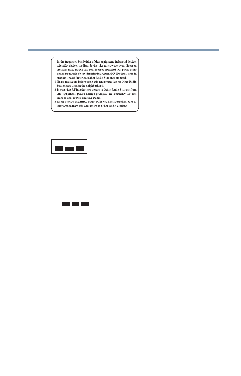
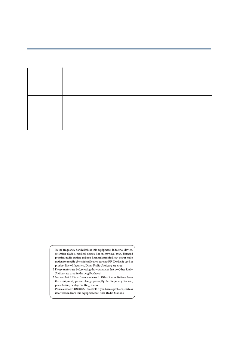
Using this Equipment in Japan
In Japan, the frequency bandwidth of 2,400 MHz to 2,483.5 MHz for second
generation low-power data communication systems such as this equipment
overlaps that of mobile object identification systems (premises radio station and
specified low-power radio station).
1. Sticker
Please put the following sticker on devices incorporating this product.
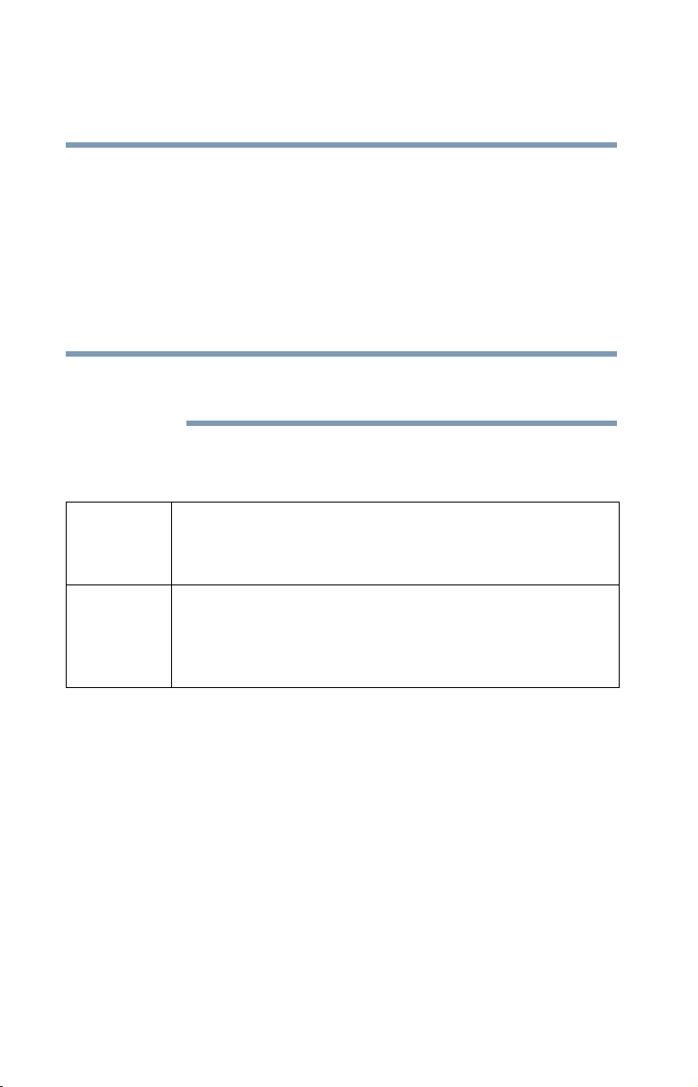
2. Indication
The indication shown below appears on this equipment.
(3)
(1) (2)
2.4DSOF4
(4)
1 2.4: This equipment uses a frequency of 2.4 GHz.
2 DS: This equipment uses DS-SS modulation.
OF: This equipment uses OFDM modulation.
3 The interference range of this equipment is less than 40m.
4 This equipment uses a frequency bandwidth from
2,400 MHz to 2,483.5 MHz.
It is possible to avoid the band of mobile object identification systems.
3. TOSHIBA Direct PC
Monday – Friday: 10:00 – 17:00
Toll Free Tel: 0120-13-1100
Direct Dial: 03-3457-5916
Fax: 03-5444-9450
13
Device Authorization
This device obtains the Technical Regulation Conformity Certification and the
Technical Conditions Compliance Approval, and it belongs to the device class of
radio equipment of low-power data communication system radio station
stipulated in the Radio Law and the Telecommunications Business Law of Japan.
The Name of the radio equipment: refer to the equipment label provided on the
computer
JAPAN APPROVALS INSTITUTE FOR TELECOMMUNICATIONS
EQUIPMENT
14
Approval Number: D01-1128JP
TELECOM ENGINEERING CENTER Approval Number: 03NY.A0018,
03GZDA0017
The following restrictions apply:
❖ Do not disassemble or modify the device.
❖ Do not install the embedded wireless module into other device.
❖ 5.17 GHz to 5.23 GHz for indoor use only
Radio approvals for wireless devices
NOTE
The following information is dependent on what type of wireless device is in
your computer.
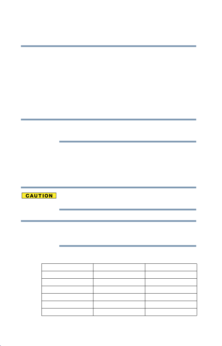
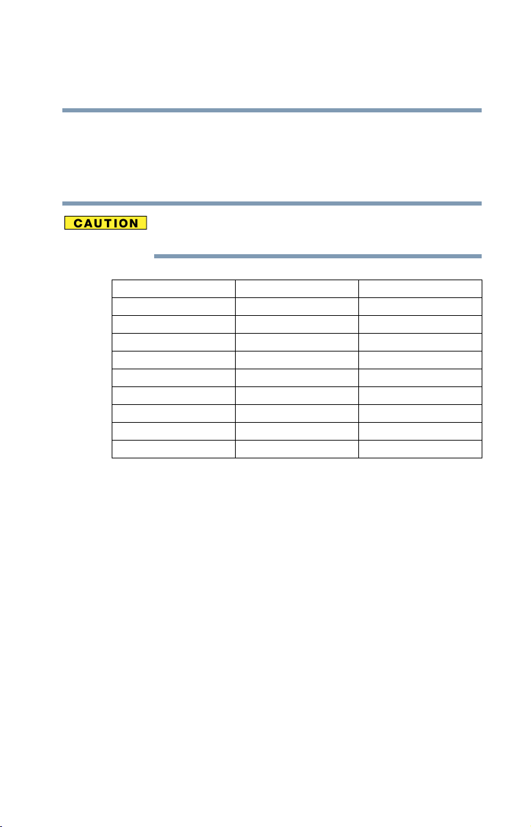
Approved Countries/Regions for use for the Atheros
AR5BMB-43/44 Mini PCI Wireless network adapter
This equipment is approved to the radio standard by the countries/regions in the
following table.
Do not use this equipment except in the countries/regions in the following
table.
NOTE
802.11b (2.4 GHz)
Australia Austria Belgium
Canada Denmark Finland
France Germany Greece
Ireland Italy Liechtenstein
Luxembourg Netherlands New Zealand
Norway Portugal Sweden
Switzerland UK USA
This device works on passive scan only.
A peer-to-peer mode is not available in 802.11a and Turbo Mode.

15
Europe - Restrictions for use of 2.4 GHz Frequencies in
European Community Countries
België/
Belgique:
Deutschland: License required for outdoor installations. Check with reseller for
France: Restricted frequency band: only channels 1 to 7 (2400 MHz and 2454
Italia: License required for indoor use. Use with outdoor installations not
Nederland: License required for outdoor installations. Check with reseller for
For private usage outside buildings across public grounds over less than
300m no special registration with IBPT/BIPT is required. Registration to
IBPT/BIPT is required for private usage outside buildings across public
grounds over more than 300m. For registration and license please
contact IBPT/BIPT.
Voor privé-gebruik buiten gebouw over publieke groud over afstand
kleiner dan 300m geen registratie bij BIPT/IBPT nodig; voor gebruik
over afstand groter dan 300m is wel registratie bij BIPT/IBPT nodig.
Voor registratie of licentie kunt u contact opnemen met BIPT.
Dans le cas d’une utilisation privée, à l’extérieur d’un bâtiment, audessus d’un espace public, aucun enregistrement n’est nécessaire pour
une distance de moins de 300m. Pour une distance supérieure à 300m un
enregistrement auprès de I’IBPT est requise. Pour les enregistrements et
licences, veuillez contacter I’IBPT.
procedure to follow.
Anmeldung im Outdoor-Bereich notwendig, aber nicht
genehmigungspflichtig.Bitte mit Händler die Vorgehensweise
abstimmen.
MHz respectively) may be used outdoors in France. Please contact
A.R.T. (http://www.art-telecom.fr) for applicable procedures to follow.
Bande de fréquence restreinte: seuls les canaux 1- 7 (2400 et 2454 MHz
respectivement) doivent être utilisés endroits extérieur en France. Vous
pouvez contacter I’Autorité de Régulation des Télécommuniations
(http://www.art-telecom.fr) pour la procédure à suivre.
allowed.
E’necessaria la concessione ministeriale anche per l’uso interno.
Verificare con i rivenditori la procedura da seguire.
procedure to follow.
Licentie verplicht voor gebruik met buitenantennes. Neem contact op
met verkoper voor juiste procedure.
16
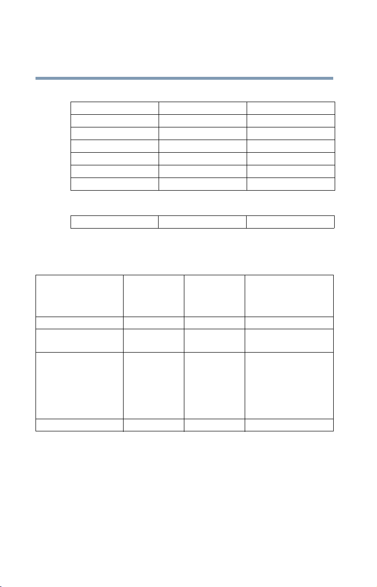
802.11a (5 GHz)
Australia Austria Belgium
Canada Denmark Finland
France Germany Greece
Ireland Italy Liechtenstein
Luxembourg Netherlands New Zealand
Norway Portugal Sweden
Switzerland UK USA
Turbo Mode (5 GHz)
Canada USA
Europe - Restrictions for use of 5 GHz Frequencies in
European Community Countries
European Community
Countries
Austria O x x
Belgium, France,
Switzerland/Lichtenstein
Denmark, Finland,
Germany, Greece,
Ireland, Italy,
Luxembourg,
Netherlands, Norway,
Portugal, Sweden, UK
Iceland, Spain O O O
O: allowed ×: forbidden
5150-5250 MHz
Channels: 36, 40, 44,
48
Indoor Only
OO x
OO O
5250-5350 MHz
Channels: 52, 56, 60,
64
Indoor Only
5470-5725 MHz
Channels: 100, 104, 108, 112,
116, 120, 124, 128, 132, 136, 140
Indoor/Outdoor
❖ To remain in conformance with European spectrum usage laws for Wireless
LAN operation, the above 2.4 GHz and 5 GHz channel limitations apply.
The user should use the wireless LAN utility to check the current channel of
operation. If operation is occurring outside of the allowable frequencies as
listed above, the user must cease operating the Wireless LAN at that
location and consult he local technical support staff responsible for the
wireless network.
❖ The 5 GHz Turbo mode feature is not allowed for operation in any
European Community country.
17
❖ This device must not be operated in ad-hoc mode using channels in the
5 GHz bands in the European Community. Ad-hoc mode provides a direct
communication between two client devices without a Wireless LAN Access
Point.
❖ This device must be used with Access Points that have employed and
activated a radar detection feature required for European Community
operation in the 5 GHz bands. This device will operate under the control of
the Access Point in order to avoid operating on a channel occupied by any
radar system in the area. The presence of nearby radar operation may result
in temporary interruption of operation of this device. The Access Point’s
radar detection feature will automatically restart operation on a channel free
of radar. You may consult with the local technical support staff responsible
for the wireless network to ensure the Access Point device(s) are properly
configured for European Community operation.
Approved Countries/Regions for use for the Atheros AR5001X
Mini PCI Wireless network adapter
This equipment is approved to the radio standard by the countries/regions in the
following table.
Do not use this equipment except in the countries/regions in the following
table.
NOTE
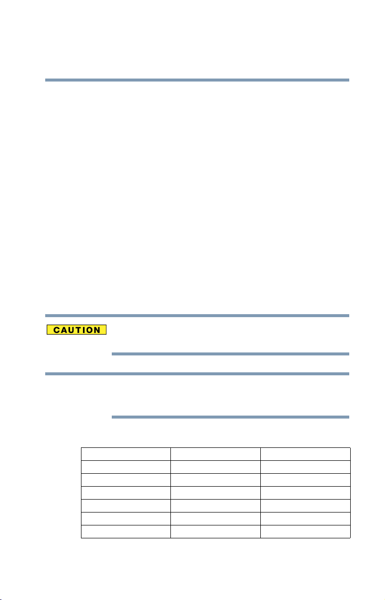
802.11b (2.4 GHz)
Australia Austria Belgium
Canada Denmark Finland
France Germany Greece
Ireland Italy Liechtenstein
Luxembourg Netherlands New Zealand
Norway Portugal Sweden
Switzerland UK USA
This device works on passive scan only.
A peer-to-peer mode is not available in 802.11a and Turbo Mode.
18
802.11a (5 GHz)
Australia Austria Belgium
Canada Denmark Finland
France Germany Greece
Ireland Italy Liechtenstein
Luxembourg Netherlands New Zealand
Norway Portugal Sweden
Switzerland UK USA
Turbo Mode (5 GHz)
Canada USA
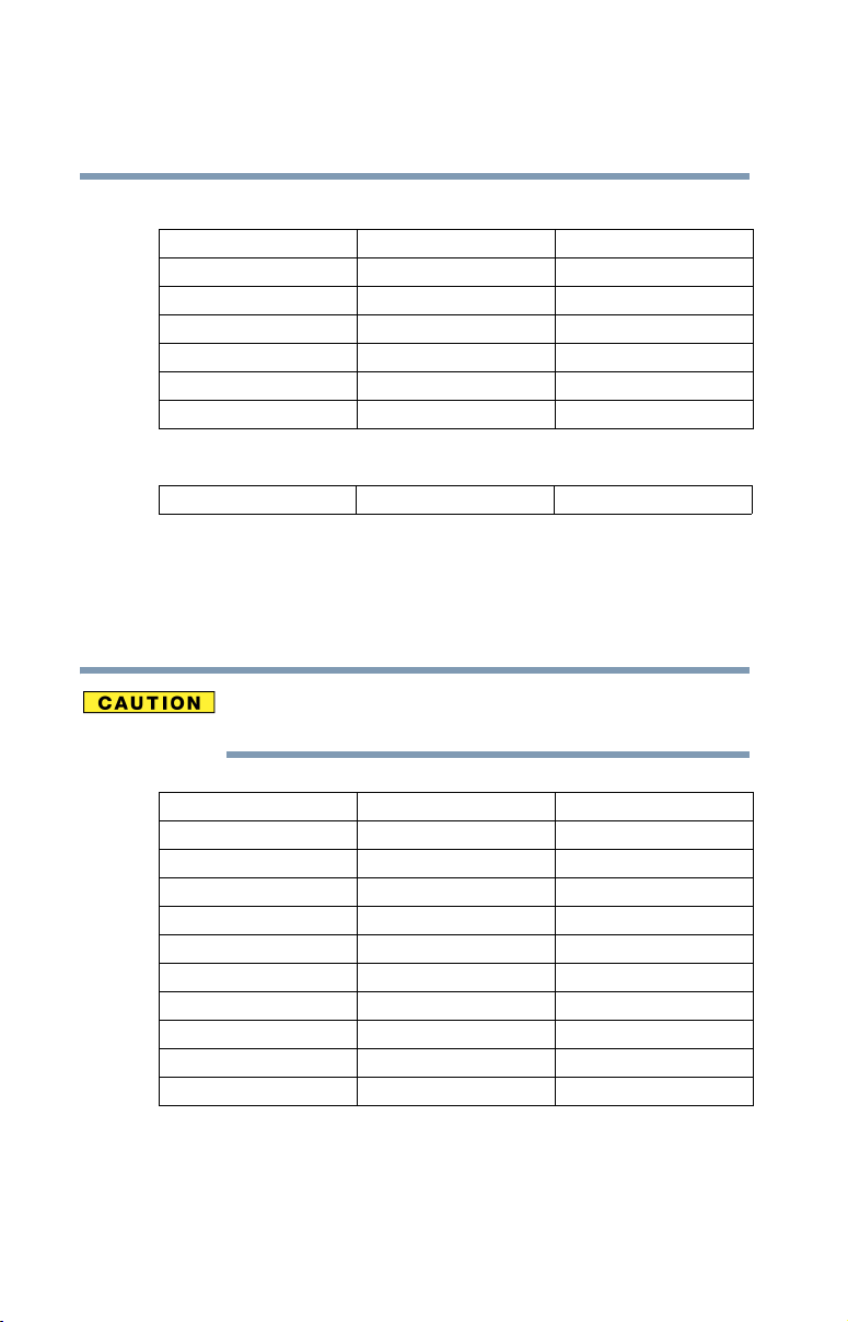
Approved Countries/Regions for use for the Intel® PRO/
Wireless LAN 2100 3B Mini PCI Adapter
This equipment is approved to the radio standard by the countries/regions in the
following table.
Do not use this equipment except in the countries/regions in the following
table.
Argentina Australia Austria
Belgium Brazil Canada
Chile Denmark Finland
France Germany Greece
Iceland Ireland Italy
Japan Liechtenstein Luxembourg
Mexico Netherlands New Zealand
Norway Peru Portugal
Singapore Spain Sweden
Switzerland UK Uruguay
USA Venezuela
19
Approved Countries/Regions for use for the Toshiba Mini PCI
Wireless LAN Card
This equipment is approved to the radio standard by the countries/regions in the
following table.
Do not use this equipment except in the countries/regions in the following
table.
Australia Austria Belgium
Canada Denmark Finland
France Germany Greece
Hong Kong Iceland Ireland
Italy Japan Liechtenstein
Luxembourg Malaysia Netherlands
New Zealand Norway Philippines
Portugal Singapore Spain
Sweden Switzerland Thailand
UK USA
Bluetooth wireless technology Interoperability
Bluetooth™ Cards from TOSHIBA are designed to be interoperable with any
product with Bluetooth wireless technology that is based on Frequency Hopping
Spread Spectrum (FHSS) radio technology, and is compliant to:
❖ Bluetooth Specification as defined and approved by The Bluetooth Special
Interest Group.
❖ Logo certification with Bluetooth wireless technology as defined by The
Bluetooth Special interest Group.

20
Bluetooth wireless technology is a new innovative technology, and TOSHIBA
has not confirmed compatibility of its Bluetooth™ products with all PCs and/
or equipment using Bluetooth wireless technology other than TOSHIBA
portable computers.
Always use Bluetooth™ cards from TOSHIBA in order to enable wireless
networks over two or more (up to a total of seven) TOSHIBA portable
computers using these cards. Please contact TOSHIBA PC product support
on Web site http://www.toshiba-europe.com/computers/tnt/bluetooth.htm in
Europe or http://www.pcsupport.global.toshiba.com in the United States for
more information.
When you use Bluetooth™ cards from TOSHIBA close to 2.4 GHz Wireless
LAN devices, Bluetooth transmissions might slow down or cause errors. If
you detect certain interference while you use Bluetooth™ cards from
TOSHIBA, always change the frequency, move your PC to the area outside of
the interference range of 2.4 GHz Wireless LAN devices (40 meters/
43.74 yards or more) or stop transmitting from your PC. Please contact
TOSHIBA PC product support on Web site http://www.toshiba-europe.com/
computers/tnt/bluetooth.htm in Europe or http://
www.pcsupport.global.toshiba.com in the United States for more
information.
Bluetooth™ and Wireless LAN devices operate within the same radio
frequency range and may interfere with one another. If you use Bluetooth™
and Wireless LAN devices simultaneously, you may occasionally experience
a less than optimal network performance or even lose your network
connection. If you should experience any such problem, immediately turn off
either one of your Bluetooth™ or Wireless LAN. Please contact Toshiba PC
product support on Web site http://www.toshiba-europe.com/computers/tnt/
bluetooth.htm in Europe or http://www.pcsupport.global.toshiba.com in the
United States for more information.
Bluetooth wireless technology and your Health
The products with Bluetooth wireless technology, like other radio devices, emit
radio frequency electromagnetic energy. The level of energy emitted by devices
with Bluetooth wireless technology however is far much less than the
electromagnetic energy emitted by wireless devices like for example mobile
phones.
Because products with Bluetooth wireless technology operate within the
guidelines found in radio frequency safety standards and recommendations,
TOSHIBA believes Bluetooth wireless technology is safe for use by consumers.
These standards and recommendations reflect the consensus of the scientific
community and result from deliberations of panels and committees of scientists
who continually review and interpret the extensive research literature.

In some situations or environments, the use of Bluetooth wireless technology
may be restricted by the proprietor of the building or responsible representatives
of the organization. These situations may for example include:
❖ Using the equipment with Bluetooth wireless technology on board of
airplanes, or
❖ In any other environment where the risk of interference to other devices or
services is perceived or identified as harmful.
If you are uncertain of the policy that applies on the use of wireless devices in a
specific organization or environment (e.g. airports), you are encouraged to ask for
authorization to use the device with Bluetooth wireless technology prior to
turning on the equipment.
Regulatory statements
This product complies with any mandatory product specification in any country/
region where the product is sold. In addition, the product complies with the
following:
European Union (EU) and EFTA
This equipment complies with the R&TTE directive 1999/5/EC and has been
provided with the CE mark accordingly.
21
Canada — Industry Canada (IC)
This device complies with RSS 210 of Industry Canada.
Operation is subject to the following two conditions: (1) this device may not
cause interference, and (2) this device must accept any interference, including
interference that may cause undesired operation of this device.”
L’utilisation de ce dispositif est autorisée seulement aux conditions suivantes: (1)
il ne doit pas produire de brouillage et (2) l’utilisateur du dispositif doit étre prét à
accepter tout brouillage radioélectrique reçu, même si ce brouillage est
susceptible de compromettre le fonctionnement du dispositif.
The term “IC” before the equipment certification number only signifies that the
Industry Canada technical specifications were met.

22
Caution: FCC Interference Statement
This device complies with part15 of the FCC rules. Operation is subject to the
following two conditions:
❖ This device may not cause harmful interference, and
❖ This device must accept any interference received, including interference
that may cause undesired operation.
Note that any changes or modifications to this equipment not expressly approved
by the manufacturer may void the authorization to operate this equipment.
Caution: Exposure to Radio Frequency Radiation
The radiated output power of the Bluetooth™ Card from TOSHIBA is far below
the FCC radio frequency exposure limits. Nevertheless, the Bluetooth™ Card
from TOSHIBA shall be used in such a manner that the potential for human
contact during normal operation is minimized.
In order to comply with FCC radio-frequency radiation exposure guidelines for
an uncontrolled environment, the Bluetooth™ Card from TOSHIBA has to be
operated while maintaining a minimum body to antenna which are located on top
of LCD distance of 20 cm.
Refer to the Regulatory Statements as identified in the documentation that comes
with those products for additional information.
The Bluetooth™ Card from TOSHIBA is far below the FCC radio frequency
exposure limits.
Nevertheless, it is advised to use the Bluetooth™ Card from TOSHIBA in such a
manner that human contact during normal operation is minimized.
NOTE
Changes or modifications made to this equipment not expressly approved by
TOSHIBA or parties authorized by TOSHIBA could void the user’s authority
to operate the equipment.
23
Taiwa n
Article 14 Unless approved, for any model accredited low power radio frequency
electric machinery, any company, trader or user shall not change the
frequency, increase the power or change the features and functions of the
original design.
Article 17 Any use of low power radio frequency electric machinery shall not affect
the aviation safety and interfere with legal communications. In event that
any interference is found, the use of such electric machinery shall be
stopped immediately, and reusing of such products can be resumed until
no interference occurs after improvement.
The legal communications mentioned in the above item refer to radio
communications operated in accordance with telecommunication laws and
regulations.
Low power radio frequency electric machinery shall resist against interference
from legal communications or from industrial, scientific and medical radio
emission electric machinery.
Using this equipment in Japan
In Japan, the frequency bandwidth of 2,400 MHz to 2,483.5 MHz for second
generation low-power data communication systems such as this equipment
overlaps that of mobile object identification systems (premises radio station and
specified low-power radio station).
1. Sticker
Please put the following sticker on devices incorporating this product.

24
2. Indication
The indication shown below appears on this equipment.
(1) (2)
(3)
2.4FH1
(4)
1 2.4: This equipment uses a frequency of 2.4 GHz.
2 FH: This equipment uses FH-SS modulation.
3 The interference range of this equipment is less than 10m.
4 This equipment uses a frequency bandwidth from 2,400 MHz to
2,483.5 MHz. It is impossible to avoid the band of mobile object
identification systems.
3. TOSHIBA Direct PC
Monday – Friday: 10:00 – 17:00
Toll Free Tel: 0120-13-1100
Direct Dial: 03-3457-5916
Fax: 03-5444-9450
Device Authorization
This device obtains the Technical Regulation Conformity Certification, and it
belongs to the device class of radio equipment of low-power data communication
system radio station stipulated in the Radio Law of Japan.
The Name of the radio equipment: EYXF2CS
TELECOM ENGINEERING CENTER
Approval Number: 01NYDA1305
The following restrictions apply:
❖ Do not disassemble or modify the device.
❖ Do not install the embedded wireless module into other device.
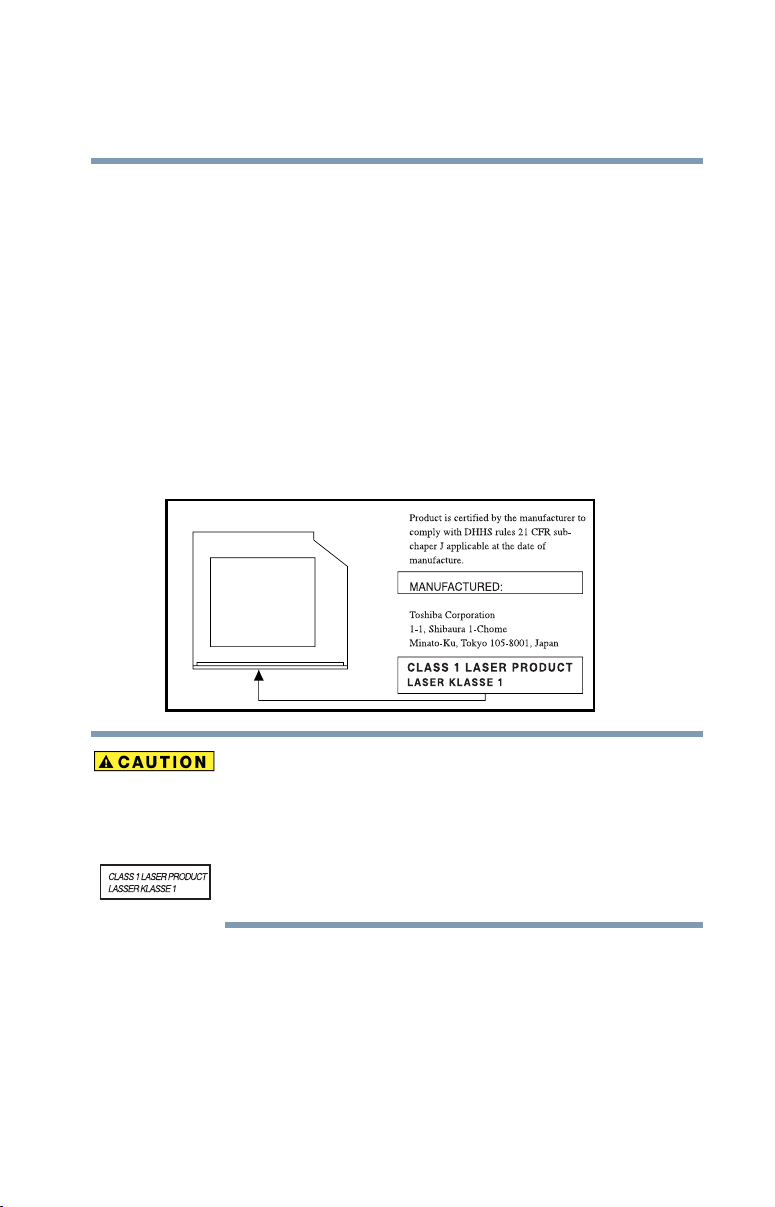
DVD-ROM, multi-function drive safety instructions
The DVD-ROM and multi-function drives employ a laser system. To ensure
proper use of this product, please read this instruction manual carefully and retain
for future reference. Should the unit ever require maintenance, contact an
authorized service location.
Use of controls, adjustments or the performance of procedures other than those
specified may result in hazardous radiation exposure.
To prevent direct exposure to the laser beam, do not try to open the enclosure.
Location of the required label
(Sample shown below. Location of the label and manufacturing information may
vary.)
25
Copyright
This guide is copyrighted by Toshiba America Information Systems, Inc. with all
rights reserved. Under the copyright laws, this guide cannot be reproduced in any
form without the prior written permission of Toshiba. No patent liability is
assumed, however, with respect to the use of the information contained herein.
©2004 by Toshiba America Information Systems, Inc. All rights reserved.
This appliance contains a laser system and is classified as a “CLASS 1 LASER
PRODUCT.” To use this model properly, read the user’s guide carefully and keep it
for your future reference. In case of any trouble with this model, please contact your
nearest “AUTHORIZED service station.” To prevent direct exposure to the laser
beam, do not try to open the enclosure.
Use of controls or adjustments or performance of procedures other than those
specified in the owner’s manual may result in hazardous radiation exposure.

26
Export Administration Regulation
This document contains technical data that may be controlled under the U.S.
Export Administration Regulations, and may be subject to the approval of the
U.S. Department of Commerce prior to export. Any export, directly or indirectly,
in contravention of the U.S. Export Administration Regulations is prohibited.
Notice
The information contained in this manual, including but not limited to any
product specifications, is subject to change without notice.
TOSHIBA CORPORATION AND TOSHIBA AMERICA
INFORMATION SYSTEMS, INC. (TOSHIBA) PROVIDES NO
WARRANTY WITH REGARD TO THIS MANUAL OR ANY OTHER
INFORMATION CONTAINED HEREIN AND HEREBY EXPRESSLY
DISCLAIMS ANY IMPLIED WARRANTIES OF MERCHANTABILITY
OR FITNESS FOR ANY PARTICULAR PURPOSE WITH REGARD TO
ANY OF THE FOREGOING. TOSHIBA ASSUMES NO LIABILITY
FOR ANY DAMAGES INCURRED DIRECTLY OR INDIRECTLY
FROM ANY TECHNICAL OR TYPOGRAPHICAL ERRORS OR
OMISSIONS CONTAINED HEREIN OR FOR DISCREPANCIES
BETWEEN THE PRODUCT AND THE MANUAL. IN NO EVENT
SHALL TOSHIBA BE LIABLE FOR ANY INCIDENTAL,
CONSEQUENTIAL, SPECIAL, OR EXEMPLARY DAMAGES,
WHETHER BASED ON TORT, CONTRACT OR OTHERWISE,
ARISING OUT OF OR IN CONNECTION WITH THIS MANUAL OR
ANY OTHER INFORMATION CONTAINED HEREIN OR THE USE
THEREOF.
Trademarks
Tecra, AccuPoint II, Fn-esse, Noteworthy and Slim SeletBay are registered
trademarks, and ConfigFree and Ask IRIS Online are trademarks, of Toshiba
America Information Systems, Inc. and/or Toshiba Corporation.
IBM and Wake on LAN are registered trademarks of IBM Corporation.
MS-DOS, Microsoft, Windows, Windows XP Professional, DirectX, Active
Desktop, DirectShow, and Windows Media are registered trademarks of
Microsoft Corporation in the United States and/or other countries.
Intel and Pentium are registered trademarks and SpeedStep is a trademark of Intel
Corporation.
LapLink is a registered trademark of Traveling Software, Inc.

Sound Blaster Pro is a registered trademark of Creative Labs, Inc.
Wi-Fi is a registered trademark of the Wi-Fi Alliance.
Dolby - Manufactured by Toshiba under license from Dolby Laboratories/ Dolby
and the double-D symbol are trademarks of Dolby Laboratories.
Bluetooth is a trademark owned by its proprietor and used by Toshiba under
license.
TouchPad is a trademark of Synaptics, Inc.
Secure Digital and SD are trademarks.
xD-Picture Card is a trademark of Fuji.
MultiMediaCard is a trademark of Infineon Technologies AG.
All other brand and product names are trademarks or registered trademarks of
their respective companies.
Computer disposal information
This product contains mercury. Disposal of this material may be regulated due to
environmental considerations. For disposal, reuse or recycling information,
please contact your local government or the Electronic Industries Alliance at
www.eiae.org.
27

Contents
Introduction............................................................................... 36
This guide ..................................................................37
Safety icons ...............................................................38
Other icons used..................................................39
Other documentation .................................................39
Service options ..........................................................40
Chapter 1: Getting Started........................................................ 41
Selecting a place to work...................................................... 41
Creating a computer-friendly environment..................... 41
Keeping yourself comfortable ..............................42
Other precautions.................................................................. 46
Important information on your computer’s
cooling fan .......................................................48
Setting up your computer..................................................... 48
Connecting to a power source......................................... 49
Charging the battery ..................................................52
Turning on the computer...................................................... 53
Opening the display panel................................................ 53
Your computer’s features and specifications .......54
28

Contents
29
Turning on the power ....................................................... 54
Setting up your software ...................................................... 55
Registering your computer with Toshiba............................ 57
Setting up other devices................................................... 57
Turning off the computer...................................................... 57
Closing the display panel.................................................. 58
Chapter 2: Connecting Other External Devices ...................... 59
Using external display devices............................................. 59
Connecting the display device ......................................... 60
Directing the display output when you
turn on the computer................................................... 61
Adjusting the quality of the external display................... 62
Video limitations................................................................ 62
Using a keyboard................................................................... 63
Connecting a keyboard ........................................63
Making your external keyboard emulate
the Fn key.........................................................63
Using a mouse...........................................................64
Connecting a mouse......................................................... 64
Connecting a local printer .................................................... 64
Connecting a USB printer.....................................65
Connecting a parallel printer ................................66
Connecting an optional external diskette drive................... 67
Connecting external speakers or headphones.................... 68
Connecting an external microphone.................................... 68
Using an expansion device................................................... 69
Adding memory .................................................................... 70
Installing memory modules............................................. 70
Using Slim SelectBay
Removing a module from the Slim SelectBay
Inserting a module into the Slim SelectBay
Inserting and removing hard drives .................................... 82
Inserting and removing PC Cards........................................ 85
®
modules.......................................... 80
®
............. 80
®
.................. 82

Contents
30
Inserting a PC Card........................................................... 86
Removing a PC Card........................................................ 87
Setting up a PC Card for your computer........................ 88
Inserting an SD® card........................................................... 88
Connecting your modem to a telephone line ..................... 89
Connecting to a phone line ............................................. 89
Using the i.LINK® port.......................................................... 90
Chapter 3: Learning the Basics................................................ 91
Computing tips...................................................................... 91
Using the keyboard............................................................... 92
Character keys ................................................................. 93
Making your keyboard emulate a full-size keyboard..... 93
Ctrl, Fn, and Alt keys......................................................... 94
Function keys.................................................................... 94
Windows® special keys.................................................... 95
Overlay keys ..................................................................... 95
Using the AccuPoint II® pointing device............................. 97
Using the TouchPad™.......................................................... 98
Control buttons................................................................. 99
Disabling or enabling the Dual Pointing Device............. 99
Using the TOSHIBA Console button ................................. 100
Starting a program.............................................................. 101
Starting a program from the Start menu...................... 102
Starting a program from Windows
Starting a program from the Run dialog box............... 103
Saving your work................................................................ 105
Printing your work.............................................................. 107
Using the DVD-ROM or multi-function drive................... 108
DVD-ROM or multi-function drive
components ...................................................109
Inserting a compact disc ............................................... 110
Removing a compact disc with the computer on ....... 113
®
Explorer............. 102

Contents
31
Removing a compact disc with the
computer turned off .......................................113
Caring for CDs and DVDs............................................... 114
Using PC Cards ................................................................... 114
Hot swapping.................................................................. 115
Using SD® cards.................................................................. 115
Using your computer at the office ..................................... 116
Using a computer lock........................................................ 116
Caring for your computer................................................... 118
Cleaning the computer................................................... 118
Moving the computer..................................................... 118
Powering down the computer ........................................... 119
Using Turn Off or Shut down......................................... 119
Using Hibernation........................................................... 122
Using Standby................................................................. 124
Toshiba’s online resources ................................................. 127
Chapter 4: Mobile Computing................................................ 128
Toshiba’s energy-saver design........................................... 128
Running the computer on battery power.......................... 129
Battery Notice.................................................................. 129
Charging the batteries..................................................... 130
Charging the RTC battery...................................130
Monitoring battery power .............................................. 132
What to do when the battery alarm sounds ..................... 134
Changing the main battery ................................................. 135
Taking care of your battery................................................. 137
Safety precautions .......................................................... 137
Maximizing battery life.................................................... 138
Disposing of used batteries safely................................. 139
Conserving power............................................................... 140
Power usage profiles in Windows
XP Professional.......................................................... 140
®

Contents
32
Using a hot key to set the power usage mode............. 141
Additional options for power.............................................. 142
Chapter 5: Exploring Your Options........................................ 143
Exploring the desktop......................................................... 143
Finding your way around the desktop.......................... 143
Exploring audio features..................................................... 147
Using external speakers or headphones...................... 148
Recording sounds.......................................................... 149
Playing an audio CD-ROM............................................. 151
Exchanging data with another computer.......................... 152
Transferring files ............................................................. 152
Getting help transferring files......................................... 152
Setting up for communications..................................... 153
Connecting the modem to a telephone line ................. 154
Connecting your computer to a network ..................... 154
Toshiba’s online resources............................................. 158
An overview of using the Internet...................................... 158
The Internet..................................................................... 158
The World Wide Web .................................................... 158
Internet Service Providers ............................................. 159
Connecting to the Internet ............................................ 159
Surfing the Internet......................................................... 160
Internet features.............................................................. 160
Uploading and downloading files from
the Internet ................................................................. 161
Chapter 6: Toshiba Utilities..................................................... 162
Fn-esse................................................................................. 163
Starting Fn-esse ............................................................. 163
Using the keyboard or pointing device to
assign keys................................................................. 165

Contents
33
Viewing existing key assignments ................................ 166
Changing or removing existing key assignments........ 167
TOSHIBA HW Setup ........................................................... 167
Accessing TOSHIBA HW Setup..................................... 167
TOSHIBA Power Saver....................................................... 170
TOSHIBA Mobile Extension................................................ 171
TOSHIBA Password Utility................................................. 173
TOSHIBA Zooming Utility................................................... 175
TOSHIBA CD/DVD Drive Acoustic Silencer...................... 176
TOSHIBA SD Memory Boot Utility .................................... 177
PC Diagnostic Tool.............................................................. 178
Echo Canceller..................................................................... 179
TOSHIBA IP Phone ............................................................. 180
Chapter 7: Keeping Your Files Safe ....................................... 182
Using passwords in Windows .......................................... 182
Setting user-level passwords ............................................ 183
Using an instant user-level password........................... 184
Using a power-on (user-level) password.......................... 185
Setting a power-on (user-level) password.................... 185
Creating a user token on an SD memory card............. 187
Deleting a power on (user-level) password.................. 187
Deleting a user token on an SD memory card............. 188
Using the power-on (user-level) password.................. 188
Using a supervisor password ............................................ 189
Setting a supervisor password...................................... 189
Creating a supervisor token on an SD
memory card.............................................................. 191
Deleting a supervisor password.................................... 191
Deleting a supervisor on an SD Memory Card ............ 192
Hard disk drive passwords................................................. 192
Setting a hard disk drive user only password
in System Setup ......................................................... 193

Contents
34
Deleting or changing a hard disk drive user
only password in System Setup............................... 194
Setting a hard disk drive master and user
password in System Setup....................................... 195
Changing the master and user passwords
in System Setup......................................................... 196
Deleting the hard disk drive master and user
passwords in the System Setup............................... 197
Chapter 8: If Something Goes Wrong................................... 199
Problems that are easy to fix....................................199
Problems when you turn on the computer...............201
The Windows® operating system is not working......202
Using Startup options to fix problems ...............203
Internet problems ..............................................204
The Windows® XP operating system can
help you .........................................................204
Resolving a hardware conflict..................................205
A plan of action..................................................205
Resolving hardware conflicts on your own ........206
Fixing a problem with Device Manager ..............207
Memory problems .............................................209
Power and the batteries .....................................210
Keyboard problems............................................211
Display problems ...............................................212
Disk drive problems...........................................214
DVD-ROM or multi-function drive problems......216
Sound system problems ....................................217
PC Card problems..............................................218
Printer problems................................................221
Modem problems...............................................222
Develop good computing habits ..............................222
If you need further assistance..................................223
Before you call ...................................................224

Contents
35
Contacting Toshiba ............................................224
Other Toshiba Internet Web sites ............................225
Toshiba’s worldwide offices.....................................226
Appendix A: Hot Keys...............................................228
Appendix B: Power Cord/Cable Connectors .............236
Appendix C: Using ConfigFree™ with your
Toshiba Computer .............................237
Getting Started.........................................................238
Starting ConfigFree ............................................238
ConfigFree Utilities...................................................239
Connectivity Doctor ...........................................239
Search for Wireless Devices ..............................242
Profile Settings ..................................................244
Quick Connect....................................................246
Using the Automatic Switch.....................................249
Semi-Automatic Switch Feature...............................250
Glossary................................................................................... 251
Index......................................................................................... 265

Introduction
Welcome to the world of powerful, portable multimedia
computing. With your Toshiba notebook computer, your
work can accompany you wherever you go.
Toshiba notebook computers provide considerable computing
power, enabling you to perform the most demanding
computing tasks from any location.
Your system comes with the Microsoft
or Windows XP Professional operating system. Your
operating system offers exciting features and easy Internet
access.
This guide contains information about your operating system
and how it functions with your Toshiba computer. For
specific information on the software, see the Microsoft
booklet that shipped with your computer.
®
Windows® XP Home
36

Introduction
This guide
37
NOTE
This guide
This guide introduces the computer’s features. You can:
❖ Read the entire guide from beginning to end.
❖ Skim through and stop when a topic interests you.
❖ Use the table of contents and the index to find specific
information.
The product specifications and configuration information are
designed for a product Series. Your particular model may not
have all the features and specifications listed or illustrated. For
more detailed information about the features and
specifications on your particular model, visit Toshiba's Web
site at pcsupport.toshiba.com.
While Toshiba has made every effort at the time of publication
to ensure the accuracy of the information provided herein,
product specifications, configurations, prices, system/
component/options availability are all subject to change
without notice. For the most up-to-date product information
about your computer, or to stay current with the various
computer software or hardware options, visit Toshiba's Web
site at pcsupport.toshiba.com.
If you are new to computers, or have not used a notebook
computer before, read through the first couple of chapters to
familiarize yourself with the components of the computer and
how to turn it on. After that, seek out whatever interests you
most.

Introduction
38
Safety icons
Safety icons
This manual contains safety instructions that must be
observed in order to avoid potential hazards that could result
in personal injuries, damage to your equipment, or loss of
data. These safety cautions have been classified according to
the seriousness of the risk, and the icons highlight these
instructions as follows:
Indicates an imminently hazardous situation which, if not
avoided, will result in death or serious injury.
Indicates a potentially hazardous situation which, if not
avoided, could result in death or serious injury.
NOTE
Indicates a potentially hazardous situation which, if not
avoided, may result in minor or moderate injury.
Indicates a potentially hazardous situation which, if not
avoided, may result in property damage.
Provides important information.

Other icons used
Additional icons highlight other helpful or educational
information:
TECHNICAL NOTE: This icon highlights technical information
about the computer.
HINT: This icon denotes helpful hints and tips.
DEFINITION: This icon indicates the definition of a term used
in the text.
Introduction
Other documentation
39
Other documentation
Your computer comes with the following documentation:
❖ This electronic user’s guide.
❖ Guides for other programs that may come preinstalled on
your computer or that are available for installation on
your Recovery media (if applicable to your system).
❖ For accessory information, visit Toshiba's Web site at
accessories.toshiba.com.
❖ The Microsoft
documentation which explains the features of the
operating system.
®
Windows® operating system

Introduction
40
Service options
Service options
Toshiba offers a full line of optional service programs to
complement its limited warranty. To stay current on the most
recent software and hardware options for your computer, and
for other product information, be sure to regularly check the
Toshiba Web site at pcsupport.toshiba.com.
If you have a problem or need to contact Toshiba, see “If you
need further assistance” on page 223.

Chapter 1
Getting Started
This chapter provides tips for working comfortably, describes
how to connect components, and explains what to do the first
time you use your computer.
Selecting a place to work
Your computer is designed to be used in a variety of locations
and situations. This section provides guidelines for setting up
your computing environment.
Creating a computer-friendly environment
Place the computer on a flat surface that is large enough for
the computer and any other items you need to use, such as a
printer. Leave enough space around the computer and other
equipment to give adequate ventilation and prevent
overheating.
41

42
Getting Started
Selecting a place to work
To keep your computer in prime operating condition, protect
your work area from:
❖ Dust, moisture, and direct sunlight.
❖ Equipment that generates a strong electromagnetic field,
such as large stereo speakers (other than speakers that are
connected to the computer) or speakerphones.
❖ Rapid changes in temperature or humidity and sources of
temperature change such as air conditioner vents or
heaters.
❖ Extreme heat, cold, or humidity.
❖ Liquids and corrosive chemicals.
If you spill liquid into the computer, turn off the computer,
unplug it from the AC power source, and let it dry out
completely before turning it on again. If the computer does not
operate correctly after you turn it back on, contact your
network administrator. Refer to “If you need further assistance”
on page 223 for more information.
Keeping yourself comfortable
Strain and stress injuries are becoming more common as
people spend more time using their computers. However,
with a little care and the proper use of the equipment, you can
work comfortably throughout the day.

Getting Started
Selecting a place to work
This section provides hints on avoiding strain and stress
injuries. For more information, consult books on ergonomics,
repetitive-motion injury, and repetitive-stress syndrome.
Using the computer keyboard incorrectly can result in
discomfort and possible injury. If your hands, wrists, and/or
arms hurt while typing, stop using the computer and rest. If the
discomfort persists, consult a physician.
Placement of the computer
Proper placement of the computer and external devices is
important to avoid stress-related injuries. Consider the
following when placing your computer.
❖ Place the computer on a flat surface at a comfortable
height and distance. You should be able to type without
twisting your torso or neck and look at the screen without
slouching.
43
❖ If you use an external monitor, the top of the screen
should be no higher than eye level.
❖ If you use a paper holder, set it at the same height and
distance as the screen.
Seating and posture
When using your computer, maintain good posture with your
body relaxed and your weight distributed evenly. Proper
seating is a primary factor in reducing work strain. Some
people find a backless chair more comfortable than a
conventional chair.

44
Getting Started
Selecting a place to work
Below eye level
Approximately
90° angles
Footrest
Correct posture and positioning of the computer
❖ Position your chair so that the keyboard is at or slightly
below the level of your elbow. You should be able to type
comfortably with your shoulders relaxed and your
forearms parallel to the floor.
If you are using a conventional chair:
❖ Your knees should be slightly higher than your hips. If
necessary, use a footrest to raise the level of your knees
and ease the pressure on the back of your thighs.
❖ Adjust the back of your chair so that it supports the lower
curve of your spine. If necessary, use a cushion to provide
extra back support. Lower-back support cushions are
available at many office supply stores.
❖ Sit with your back straight so that your knees, hips, and
elbows form approximately 90-degree angles when you
work. Do not slump forward or lean back too far.
Lighting
Proper lighting can improve the readability of the display and
reduce eyestrain.
❖ Position the display panel or external monitor so that
sunlight or bright indoor lighting does not reflect off the
screen. Use tinted windows or shades to reduce glare.

Getting Started
Selecting a place to work
❖ Avoid placing your computer in front of a bright light that
shines directly into your eyes.
❖ If possible, use soft, indirect lighting in your computer
work area.
Your LCD display has a brightness approaching that of a TV
device. We recommend that you adjust the brightness of your
LCD to a comfortable level to prevent possible strain on your
eyes.
45
Arms and wrists
❖ Avoid bending, arching, or twisting your wrists. Keep
them in a relaxed, neutral position while typing.
❖ Exercise your hands, wrists, and arms to improve
circulation.
Using the computer keyboard incorrectly may result in
discomfort and possible injury. If your hands, wrists, and/or
arms bother you while typing, stop using the computer and
rest. If the discomfort persists, consult a physician.
Work habits
The key to avoiding discomfort or injury from strain is to
vary your activities. If possible, schedule a variety of tasks
into your working day. Finding ways to break up the routine
can reduce stress and improve your efficiency.
❖ Take frequent, short breaks to change position, stretch
your muscles, and relieve your eyes. A break of two or
three minutes every half hour is more effective than a
long break after several hours.

Getting Started
46
Other precautions
❖ Avoid performing repetitive activities for long periods.
Intersperse such activities with other tasks.
❖ Focusing your eyes on your computer screen for long
periods can cause eyestrain. Look away from the
computer frequently and focus your eyes on a distant
object for at least 30 seconds.
Your LCD display has a brightness approaching that of a TV
device. We recommend that you adjust the brightness of your
LCD to a comfortable level to prevent possible strain on your
eyes.
Other precautions
Your notebook computer is designed to provide optimum
safety and ease of use, and to withstand the rigors of travel.
You should observe certain precautions to further reduce the
risk of personal injury or damage to the computer.
❖ Avoid prolonged physical contact with the underside of
the computer.
If the computer is used for long periods, its case can become
very warm. While the temperature may not feel too hot to the
touch, if you maintain physical contact with the computer for
a long time (if you rest the computer on your lap, for
example), your skin might suffer low-heat injury.

Getting Started
Other precautions
Some PC Cards can become hot with prolonged use. If two
cards are installed, both can become hot even if only one is
being used. Overheating of a PC Card can result in errors or
instability in its operation.
Be careful when you remove a PC Card that has been used for
a long period.
Never apply heavy pressure to the computer or subject it to
sharp impacts. Excessive pressure or impact can damage
computer components or otherwise cause your computer to
malfunction.
❖ Avoid spilling liquids into the computer’s keyboard.
If you do spill a liquid that gets into the keyboard, turn off the
computer immediately. Leave the computer turned off
overnight to let it dry out before you use it again.
47
❖ Never turn off the computer if a drive light indicates a
drive is active.
Turning off the computer while it is reading from or writing to
a disk may damage the disk, the drive, or both.
❖ Keep the computer and disks away from objects that
generate strong magnetic fields, such as large stereo
speakers.
Information on disks is stored magnetically. Placing a magnet
too close to a disk can erase important files.
❖ Scan all new files for viruses.
This precaution is especially important for files you receive
via email or download from the Internet. Occasionally, even
new programs you buy from a supplier may contain a
computer virus. You will need a special program to check for
viruses. Ask your dealer to help you.

Getting Started
48
Setting up your computer
Important information on your computer’s cooling fan
Your computer may have a CPU cooling fan that cools the
CPU by drawing outside air into the computer. The cooling
fan may be located on the bottom of the computer.
To prevent possible overheating of the CPU, make sure the air
intake on the cooling fan is not blocked. The fan draws in air
by creating a vacuum. If the fan is blocked, it could cause the
CPU to run at a lower performance level or cause the computer
to shut down. Loose items such as notebook and tissue paper,
plastic wrappers, or other similar materials can block the air
intake, preventing air from reaching the CPU. Do not use the
computer on surfaces with objects that can be drawn in by the
cooling fan.
NOTE
The cooling fan location will vary depending on the computer.
Setting up your computer
TECHNICAL NOTE: You must complete all set-up steps up to
“Setting up your software” on page 55 before adding external
or internal components to your computer. These components
include, but are not limited to, a mouse, keyboard, printer,
memory, and PC cards.
Your computer comes with a rechargeable battery pack that
must be charged before you can use it.
To use external power or to charge the battery, you must
attach the AC adapter. See “Connecting to a power source”
on page 49.

Getting Started
Setting up your computer
To register your computer online, or to sign up for an Internet
account, you must connect the built-in modem to a telephone
line.
Before adding any of these devices to the computer, be sure
to complete “Setting up your software” on page 55.
After setting up your computer, you may want to:
❖ Add more memory. See “Adding memory” on page 70.
❖ Connect a mouse. See “Connecting a mouse” on page 64.
❖ Connect a full-size keyboard. See “Using a keyboard” on
page 63.
❖ Connect an external monitor. See “Using external display
devices” on page 59.
❖ Connect a local printer. See “Connecting a local printer”
on page 64.
❖ Install PC Cards. See “Inserting and removing PC Cards”
on page 85.
49
For more information on installing specific devices, see
“Connecting Other External Devices” on page 59.
Connecting to a power source
Your computer requires power to operate. Use the power
cord/cable and AC adapter cord to connect the computer to a
live electrical outlet, or to charge the computer’s battery.

50
Power cord/cable
Getting Started
Setting up your computer
AC adapter cord
AC adapter
Sample power cord/cable and AC adapter cord
Hold the power cord/cable by its plug when you connect/
disconnect it. Do NOT pull the cord/cable itself. Doing so may
damage the power cord/cable and result in a short circuit or
electric shock.
When you connect the AC adapter to the computer, always
follow the steps in the exact order as described in the User’s
Manual. Connecting the power cord/cable to a live electrical
outlet should be the last step; otherwise, the adapter DC output
plug could hold an electrical charge and cause an electrical
shock or minor bodily injury when touched. As a general
safety precaution, avoid touching any metal parts.
Use only the AC adapter supplied with your computer or an
equivalent adapter that is compatible. Use of any incompatible
adapter could damage your computer. Toshiba assumes no
liability for any damage caused by use of an incompatible
adapter.

Getting Started
Setting up your computer
To connect AC power to the computer:
1 Connect the power cord/cable to the AC adapter.
Sample connecting the power cord/cable to the AC adapter
cord
Handling the cord on this product will expose you to lead, a
chemical known to the State of California to cause birth defects
or other reproductive harm. Wash hands after handling.
51
2 Plug the AC adapter cord into the DC-IN on the back of
the computer.
Sample connecting the AC adapter cord to the computer
3 Connect the power cord/cable to a live electrical outlet.
The AC power indicator glows when the computer is
connected to an external power source.

52
Getting Started
Charging the battery
The battery light:
❖ Glows amber while the battery is being charged.
❖ Glows green when the battery is fully charged.
❖ Is unlit when the computer is not connected to an external
power source. For information on determining battery
power, see “Monitoring battery power” on page 112.
Damaged power cords/cables can cause fire or electric shock.
Never modify, forcibly bend, place heavy objects on top of, or
apply heat to the power cord/cable.
If the power cord/cable becomes damaged or the plug
overheats, discontinue use. There is a risk of electric
shock.
Never remove the power plug from the outlet with wet hands.
Doing so may cause an electric shock.
Charging the battery
To charge the main battery, plug the computer into a live wall
outlet. It takes several hours to charge the battery with the
computer off. It takes much longer to charge the battery while
the computer is on. For more information on battery use, see
“Running the computer on battery power” on page 108.
Once the battery is charged for the first time, avoid leaving the
computer plugged in and turned off for more than a few hours
at a time. Continuing to charge a fully charged battery can
damage the battery.

Getting Started
Turning on the computer
TECHNICAL NOTE: When your computer is using all of the
power provided by the AC Adaptor to run applications,
features, and devices, the recharging of the battery can not
occur. Your computer's Power Saver utility can be used to
select a power level setting that reduces the power required for
system operation and will allow the battery to recharge.
53
NOTE
Battery life and charge time may vary depending on the
applications, power management settings, and features used.
Turning on the computer
The computer is now ready for you to turn it on and begin
using it.
Opening the display panel
1 Slide the display latch to the right.
2 Lift the display panel.
To avoid damaging the display panel, do not force it beyond
the point where it moves easily
Never lift the computer by the display panel.
Small bright dots may appear on your TFT display when you
turn on your computer. Your display contains an extremely
large number of thin-film transistors (TFT) and is
manufactured using high-precision technology. Any small
bright dots that may appear on your display are an intrinsic
characteristic of the TFT manufacturing technology.

54
Getting Started
Turning on the computer
NOTE
Over a period of time, and depending on the usage of the
computer, the brightness of the LCD Screen will deteriorate.
This is an intrinsic characteristic of LCD technology.
Screen will dim when the computer is operated on battery
power and you may not be able to increase the brightness of
the screen.
Your computer’s features and specifications
Certain notebook chassis are designed to accommodate all
possible configurations for an entire product Series. Your
selected model may not have all the features and
specifications corresponding to all of the icons or switches
shown on the notebook chassis, unless you have selected all
those features.
Below are examples of some of the many possible icons that
may come on your computer:
Sample system icons
This information applies to all the features and icons
described in this guide.
Turning on the power
To turn on the computer:
1 Make sure any external devices (such as the AC adapter,
if you plan to use AC power rather than battery power)
are properly connected and ready.
2 Check to ensure that any diskette drives are empty.

Getting Started
Setting up your software
3 Press and hold the power button in until the on/off light
on the system indicator panel glows green—about one
second.
Sample turning on the power
The preinstalled operating system will load automatically.
When you turn on the computer for the first time, don’t turn off
the power again until the operating system has loaded
completely.
55
Never turn off the computer while any drive is in use.
Setting up your software
NOTE
The first time you turn on your computer, the Setup Wizard
guides you through steps to set up your software.
The name of windows displayed, and the order in which
windows appear, may vary according to your software setup
choices.

56
Getting Started
Setting up your software
1 From the welcome screen, click Next to enter the Setup
Wizard.
2 Confirm acceptance of Microsoft’s End User License
Agreement and click Next.
3 Enter the computer name and description and click Next
or Skip.
The computer pauses for a moment while checking for an
internet connection.
A window displays the message “An Internet connection
could not be chosen.”
4 Click Skip to exit the process or Next to continue.
NOTE
5 Click Ye s to register or No to exit the process.
NOTE
6 Enter your personal information in the registration
7 Click Finish to complete the process.
To register online, your computer’s modem must be connected
to a voice-grade telephone line, or the Internet via a Local Area
Network.
A window will display asking if you wish to register with
Toshiba and Microsoft.
If you click No, you may register with Toshiba by clicking the
Register with Toshiba icon on the desktop.
window.
Your computer restarts automatically.

Getting Started
Registering your computer with Toshiba
Registering your computer with Toshiba
Product registration is strongly recommended, and allows
Toshiba to send Customer periodic updates, announcements,
and special offers applicable to the product. Product
registration can be completed during the initial start up
process of your computer. If you opt not to register at that
time, you can either double-click the icon on your desktop or
go to the Toshiba Web site at www.register.toshiba.com.
Customer failure to complete Product Registration will not
diminish Customer rights under this limited Warranty.
Setting up other devices
You may want to take this time to set up your printer or other
peripheral devices. For more information, see “Connecting a
local printer” on page 64.
Turning off the computer
57
It is a good idea to turn off your computer when you are not
using it for a while.
If you are using the computer for the first time, leave the
computer plugged into a power source (even though the
computer is off) to fully charge the main battery. With the
computer off, it may take up to three hours to recharge the
main battery.
When you power down the computer, you have three options
to choose from: Turn Off (or Shut down), Hibernate and
Standby. Each option has its advantages.
❖ Use the Turn Off command if you are using the
Windows
Windows
connected to a domain server.
®
XP Home version operating system, or the
®
XP Professional operating system when not

58
Getting Started
Turning off the computer
❖ Use the Shut down command if you are using the
Windows
connected to a domain server.
❖ If you have work in progress and are not connected to a
network, use the Windows
commands to save your system settings to memory so
that, when you turn on the computer again, you will
automatically return to where you left off.
❖ To leave the computer off for a longer period, you can use
the Windows
a domain server or the Shut down when connected to a
domain server instead.
®
XP Professional operating system and
®
Turn Off command when not connected to
Never turn off the computer while any drive is in use. Doing so
may damage the media in use and result in loss of data. For
more information, see “Powering down the computer” on
page 99.
Closing the display panel
When you are finished, shut the computer down and close the
display panel to keep dust and dirt out of the computer.
®
Standby or Hibernate
If you close the computer while it is still on, these actions will
occur:
❖ If you have the LCD power-saver feature set, the LCD
panel will automatically turn off until you open it again.
❖ If you have the audible warning set, the computer will
beep to notify you that it is still on.
❖ If you have an action feature set, the computer will
perform either: Nothing, Standby, or Hibernate (see
“Using Hibernation” on page 122).

Chapter 2
Connecting Other
External Devices
This chapter describes how to connect devices that can
increase the capabilities of your computer.
Using external display devices
Your computer comes with a built-in LCD display, but you
can also connect three different types of external display
devices to one of two available video ports:
❖ A television via the S-video port.
❖ A video display device, such as a video projection unit,
via the S-video port.
❖ An external monitor or projector via the RGB (monitor)
port.
Connect a television, video projector, monitor, or other
display device to your computer and then configure your
computer for the type of device you are connecting. The
following sections describe how to do this in detail. Also,
refer to the documentation for your operating system and
devices.
59

Connecting Other External Devices
60
Using external display devices
Connecting the display device
If you are connecting a television or other video display
device to the computer’s S-video port, first refer to the next
two subsections.
If you are connecting an SVGA monitor, skip to “Connecting
an external monitor or projector” on page 61.
Selecting video cables
To connect a device to the S-video port, you’ll need to
purchase an S-video cable. For the best video quality, always
use a properly shielded cable.
HINT: Toshiba recommends using a cable no longer than
20 feet (approximately 6 meters).
Using a poor quality cable may result in a dull or fuzzy
picture, poor color, ghosting, video noise, or loss of video.
Connecting to the S-video port
NOTE
1 Connect one end of the S-video cable to the external
2 Connect the other end of the S-video cable to the S-video
3 Turn on the external video device.
Video cables are not included with your computer. To connect
a device to the S-video port, you’ll need to purchase an Svideo cable.
video device.
Refer to the documentation provided with the device for the
location of its S-video-in port.
port on the back side of the computer.

Connecting Other External Devices
Using external display devices
4 Set the display mode by pressing Fn + F5 or by using the
Display Properties settings. For more information, see
“Directing the display output when you turn on the
computer” below.
61
Connecting an external monitor or projector
You can easily attach an external monitor or projector to your
computer if you need a larger screen. To do this:
1 Connect the monitor’s video cable to the RGB port on the
back of the computer.
2 Connect the device’s power cable to a live electrical
outlet.
3 Turn on the external device.
4 Set the display mode by pressing
Display Properties settings. For more information, see
“Directing the display output when you turn on the
computer” below.
Fn + F5 or by setting the
Directing the display output when you turn on the computer
Once you’ve connected an external display device, you can
choose to use the internal display only, the external device
only, or both simultaneously. The quickest way to change the
display output settings is to use the display hot key (
1 Press
2 While holding down
Fn and F5 simultaneously.
Fn, press F5 repeatedly until the
setting you want takes effect.
This hot key cycles through the settings in the following
order:
❖ Built-in display only
❖ Built-in display and external device simultaneously
❖ External device only
Fn + F5):

62
Connecting Other External Devices
Using external display devices
❖ Built-in display and TV (or other external video device)
simultaneously
❖ TV (or other external video device) only
3 Release the
TECHNICAL NOTE: You can also change these settings using
the Display Properties Box.
Set the option for the video controller by clicking Start, then
Control Panel and clicking Display. Choose the Settings tab,
click the Advanced button, select Display Device, select the
applicable Monitor type, click Apply or OK.
For more information on switching the display output, see
“Display modes” on page 233.
Fn key.
Adjusting the quality of the external display
To obtain the best picture quality from your television (or
other video display device), you may need to adjust the video
settings. See the video device documentation for additional
configuration steps.
TECHNICAL NOTE: In order to use one of the simultaneous
modes, you must set the resolution of the internal display
panel to match the resolution of the external display
device.The external display device must support a resolution
of 640 x 480 or higher.
Video limitations
Keep in mind that the quality of the display will be limited to
the capabilities of the external video device.

❖ If the external video device, such as an SVGA monitor, is
capable of displaying at a maximum resolution of 640 x
480 and your system is set for a higher resolution, only
part of the desktop will appear on the screen. You can
scroll to view the “lost” area.
❖ Since most televisions and video projectors overscan by
15 to 20 percent, some of the desktop will be outside the
viewing area. You can scroll to view the edge of the
desktop.
❖ If you use the display hot key (Fn + F5) to change the
display output with the LCD Display Stretch option
enabled and the display area (resolution) set to 640 x 480
or 800 x 600, the image on the internal display panel may
appear stretched.
Using a keyboard
If you prefer to use a full-size keyboard, you can attach a
USB keyboard to a USB port or a serial keyboard to an
optional Advanced Port Replicator III. See your Toshiba sales
representative for more information.
Connecting Other External Devices
Using a keyboard
63
Connecting a keyboard
To connect a USB keyboard, gently push the keyboard cable
into the USB port. To connect a serial keyboard, gently push
the keyboard cable into the serial port of an optional
Advanced Port Replicator III.
Making your external keyboard emulate the Fn key
An external keyboard does not have the Fn key provided by
the computer’s built-in keyboard. You can use the
Emulation option in Toshiba Hardware Setup to assign an
external keyboard key combination that will emulate the
internal keyboard’s
Fn key.
Fn Key

64
Connecting Other External Devices
Using a mouse
In Toshiba Hardware Setup, you can emulate the Fn keys by
setting key combinations in the keyboard option of the utility.
See “TOSHIBA HW Setup” on page 167 for more
information.
NOTE
The Fn emulation key is not supported when using a USB
keyboard.
Using a mouse
If you prefer to use a standard mouse, you can attach a USB
mouse to a USB port or a serial mouse to an optional
Advanced Port Replicator III. See your Toshiba sales
representative for more information.
Connecting a mouse
To connect a USB mouse, gently push the keyboard cable
into the USB port. To connect a serial mouse, gently push the
mouse cable into the serial port of an optional Advanced Port
Replicator III.
Connecting a local printer
NOTE
Read the documentation that came with your printer. Follow
the manufacturer’s instructions when connecting a local
printer.
You must supply the proper printer cable. If one did not come
with your printer, you may purchase one from an electronics or
computer store.
If your printer is ECP- or IEEE-compliant, make sure your
printer cable is an IEEE 1284 cable.

Connecting Other External Devices
Connecting a local printer
Your printer documentation may require you to install the
printer software before physically connecting the printer to
your computer. If you do not install the software as instructed
by the printer manufacturer, the printer may not function
correctly.
Never connect the printer cable while the computer’s power is
on. Doing so may damage the printer, the computer, or both.
65
NOTE
You must supply the proper printer cable. If one did not come
with your printer, you may purchase one from an electronics or
computer store.
Connecting a USB printer
These instructions assume you have a USB printer, consult
the document that came with your printer to verify the
connection type.
To connect the printer:
1 If the computer is on, turn it off.
2 Connect the printer cable to the printer and then connect
the other end to one of the computer’s USB ports.
3 Plug the printer’s power cable into a live electrical outlet.
4 See your printer documentation for additional
configuration steps or see “Setting up a printer,” below.
For more information on getting your printer to print, see
“Printing your work” on page 107.

Connecting Other External Devices
66
Connecting a local printer
Connecting a parallel printer
These instructions assume you have a parallel printer.
To connect the printer:
1 If the computer is on, turn it off.
2 Connect the printer cable to the printer and to the
computer’s parallel port. Use the printer cable illustration
as a connection guide.
To the computer
Identifying the ends of a parallel printer cable
3 Plug the printer’s power cable into a live electrical outlet.
4 See your printer documentation for additional
configuration steps.
For more information on getting your printer to print, see
“Printing your work” on page 107.
To the printer

Connecting Other External Devices
Connecting an optional external diskette drive
67
Connecting an optional external diskette drive
Some operations, such as creating a password service
diskette, require a diskette drive designed for use with 3.5inch diskettes.
Sample optional external USB diskette drive
To connect an optional external USB diskette drive, connect
the cable to one of the USB ports.
Connecting an optional external USB diskette drive

Connecting Other External Devices
68
Connecting external speakers or headphones
Connecting external speakers or headphones
Before using headphones to listen to an audio CD, turn the
volume dial down. Playing the CD with the volume set too
high could damage your ears.
To attach an external stereo output device (headphone or
external speakers):
1 Locate the headphone jack on the right side of the
computer.
2 Using any necessary adapters, plug the cable from the
external audio device into the headphone jack. The
headphone jack requires a 3.5 mm, 16-ohm stereo jack.
When the headphone is inserted, the internal speakers are
automatically disabled.
For more information on using headphones or external
speakers, see “Using external speakers or headphones” on
page 148.
Connecting an external microphone
Your computer comes equipped with an internal microphone,
but to record higher quality sounds, you can attach an
external microphone:
1 Locate the microphone jack on the right side of the
computer.
2 Plug the microphone cord into the microphone jack.
3 Turn on the microphone.
The internal microphone is automatically disabled.

Connecting Other External Devices
Using an expansion device
Once the external microphone is connected, the recording
process is the same as with the built-in microphone. For more
information, see “Recording sounds” on page 149.
HINT: When an external microphone is connected while using
TOSHIBA IP Phone (see “TOSHIBA IP Phone” on page 180),
you can adjust for audio feedback by using the Echo Canceller
utility. For more information see “Echo Canceller” on
page 179.
Using an expansion device
The expansion port is used to connect your computer to an
expansion device. This is an excellent investment if you are
using your computer both in and out of the office.
69
When you return to your desk, you can then connect to your
network, print reports from your computer, or use a mouse
instead of the AccuPoint II. Connecting cables for each of
these devices every time you return to the office is timeconsuming and inconvenient.
With an expansion device, you can leave external devices
connected while you are using your computer away from
your desk. When you return, you can quickly connect your
computer and have immediate access to all the devices.
For more information, see the accessories information
package that comes with the device or visit
accessories.toshiba.com.

Connecting Other External Devices
70
Adding memory
Adding memory
HINT: To purchase additional memory modules, see the
accessories information packaged with your system or visit
accessories.toshiba.com.
Your notebook computer is equipped with two memory slots
which can provide various memory configurations. When
additional memory is added, or original memory replaced, it
is recommended that you use only compatible memory. In the
event original memory is replaced with invalid memory, the
system will beep and will not boot beyond the BIOS memory
check. A message may display. If this occurs, contact
Toshiba’s support center at (800) 457-7777.
Installing memory modules
Additional memory modules can be installed in your
computer. There are two memory expansion slots; the
secondary slot located on the bottom of your computer, and
the primary slot located under your computer’s keyboard.
Normally, you will install or replace a memory module in the

Connecting Other External Devices
Adding memory
secondary slot—the secondary slot is designed for quick
installation.
To avoid damaging the computer’s screws, use a standard
Phillips no.0 screwdriver (for primary memory installation) or
Phillips no.1 screwdriver (for secondary memory installation)
that is in good condition.
71
NOTE
NOTE
If you install any memory module in your computer, be sure
that a memory module resides in the primary slot. The
computer does not boot when the primary slot is vacant.
Toshiba recommends installing a memory module in the
secondary slot prior to removing and installing a memory
module in the primary slot, due to the ease of installation.
Primary memory module installation requires significant
computer disassembly and reassembly. If you are
uncomfortable with this, please contact your Toshiba sales
representative for a service professional to complete this
procedure.
Installing a memory module in the secondary slot
If the computer is on, begin at step 1; otherwise, skip to step
2.
1 Shut down your computer completely using the Shut
down or Turn Off command.
See “Turning off the computer” on page 57.

72
Connecting Other External Devices
Adding memory
2 Unplug the computer.
Installing a memory module with the computer’s power on may
damage the computer, the module, or both.
3 Close the display panel and remove any cables you may
have connected.
4 Turn the computer upside down, remove the battery, and
locate the memory module cover to the memory slot.
Memory module cover
Locating the sample memory module cover
5 Using a standard Phillips no. 1 screwdriver, unscrew the
screw that secures the memory module cover, then
remove the memory module cover. Place the screw and
the cover in a safe place so that you can retrieve them
later.

Connecting Other External Devices
Adding memory
Removing the sample memory module cover
6 If a memory module exists in the slot, remove it as
detailed in “Removing a memory module from the
secondary slot” on page 74. If no memory module exists
in the slot, proceed to step 7.
Static electricity can damage the memory module. Before you
handle the module, touch a grounded metal surface to
discharge any static electricity you may have built up.
73
To avoid damaging the memory module, be careful not to
touch its pin connector on the side you insert into the
computer.
7 Remove the new memory module from its antistatic
packaging.
8 Holding the memory module at an angle by its edges so
that the gold connector bar faces the slot, fit the module
into the socket.
9 Gently press down on the memory module until the clips
snap into place.
Do not force the module into position. The memory module
should be level when secured in place.

74
Connecting Other External Devices
Adding memory
Inserting the sample memory module into the secondary slot
Avoid touching the connectors on the memory module or on
the computer. Grease or dust on the connectors may cause
memory access problems.
10 Replace the cover slot and the screw.
11 Turn the computer over and restart it.
When you turn on the computer, it automatically recognizes
the additional memory.
Removing a memory module from the secondary
slot
If you need to remove a secondary memory module:
1 Complete steps 1–5 in “Installing a memory module in
the secondary slot” to shut down the computer and
remove the memory module cover.

Connecting Other External Devices
Adding memory
Do not try to remove a memory module with the computer
turned on. You can damage the computer and the device.
Do not remove the memory module while the computer is in
Standby mode. The computer could hang up the next time you
turn it on and data in memory will be lost. In either of the
above cases, the Standby configuration will not be saved.
The following message appears when you turn on the power:
Warning: Resume Failure
Press Any Key To Continue
If the computer hangs up when you turn it on, perform the
following: Press the power button and hold it down for five
seconds, then turn the power on again.
2 Pull the clips away from the memory module.
The memory module pops up partially.
75
3 Carefully remove the module from the slot.
Removing the sample memory module
4 Replace the cover plate and screw.
5 Turn the computer over and restart it.

76
Connecting Other External Devices
Adding memory
Installing a memory module in the primary slot
NOTE
NOTE
If the computer is on, begin at step 1; otherwise, skip to step
2.
1 Shut down your computer completely using the Shut
2 Unplug the computer.
Primary memory module installation requires significant
computer disassembly and reassembly. If you are
uncomfortable with this, please contact your Toshiba sales
representative for a service professional to complete this
procedure.
If you install any memory module in your computer, be sure
that a memory module resides in the primary slot. The
computer does not boot when the primary slot is vacant.
Toshiba recommends installing a memory module in the
secondary slot first (due to the ease of installation) before
removing and installing a memory module in the primary slot.
down or Turn Off command.
See “Turning off the computer” on page 57.
Installing a memory module with the computer’s power on may
damage the computer, the module, or both.
3 Close the display panel and remove any cables you may
have connected.
4 Turn the computer upside down and remove the battery.
5 Locate and remove the retaining screw. Place the screw in
a safe place so that you can retrieve it later.

Connecting Other External Devices
Adding memory
Removing the sample retaining screw
6 Turn the computer over and slide the display latch to the
right and open the display panel.
7 Insert a thin object under the rim of the keyboard brace
and lift out the brace.
77
Removing the sample keyboard brace

78
Connecting Other External Devices
Adding memory
8 Remove two screws securing the keyboard. Place the
screws in a safe place so that you can retrieve them later.
9 Lift up the back of the keyboard, rotate it toward you and
lay in face down on the palm rest.
Rotating the sample keyboard
10 Remove the retaining screw and the metal brace. Place
the screw in a safe place so that you can retrieve it later.
11 Remove the existing memory module from the slot by
pulling the clips away from the memory module. Place
the module in antistatic packaging and store it in a safe
place.
Removing the sample metal brace

Connecting Other External Devices
Adding memory
12 Remove the new memory module from its antistatic
packaging.
13 Holding the memory module by its edges so that the gold
connector bar faces the slot, fit the module into the socket
so it lies flat and is secured by two latches on either side.
The clips on either side of the module will click to secure the
module.
79
Installing the sample memory module in the primary slot
14 Replace the metal brace and the screw.
15 Insert the tabs on the front of the keyboard into
corresponding notches on the computer, seat the
keyboard, and secure it with the two screws.
16 Seat the keyboard brace and press to secure latches.
17 Install the battery pack.
18 Turn the computer over and restart it.
When you turn on the computer, it automatically recognizes
the additional memory.

Connecting Other External Devices
80
Using Slim SelectBay® modules
Using Slim SelectBay® modules
The Slim SelectBay® gives you additional flexibility. By
inserting and removing Slim SelectBay modules, you can
configure your computer for the task at hand without having
to carry unnecessary components with you when you travel.
For example, any one of several modules can be used in the
Slim SelectBay:
❖ DVD-ROM drive.
❖ Multi-function drive
❖ Weight saver insert (a “honeycomb” piece of plastic) that
reinforces the Slim SelectBay for travel.
❖ Secondary battery
❖ Secondary hard disk drive (HDD)
HINT: Items from this list that did not come with your computer
can be purchased separately. See the accessories information
packaged with your system or visit accessories.toshiba.com.
Removing a module from the Slim SelectBay
NOTE
1 Do one of the following:
Use caution when lifting or turning your computer. Failure to
do so may result in damage to components, such as cables,
attached to your computer, or to the computer itself.
❖ Turn off the computer.
❖ Leave the computer on and hot swap the module. First,
stop the module by clicking the Safely Remove
®

Connecting Other External Devices
Using Slim SelectBay® modules
Hardware icon on the System tray. After the module is
stopped, it is safe to remove it.
2 Slide the Slim SelectBay release toward the back of the
computer.
Unlatching the sample Slim SelectBay
3 Slide the Slim SelectBay out of the computer.
81
Sliding out the sample module
If you are removing the weight saver, retain it for transporting
the computer when no other module is installed in the
Slim SelectBay.

82
Connecting Other External Devices
Inserting and removing hard drives
Inserting a module into the Slim SelectBay
To install a module into the Slim SelectBay, simply slide the
module all the way into the Slim SelectBay until the latch
locks into place.
®
Inserting and removing hard drives
Your computer can use hard drives with various capacities.
Depending upon the original hard drive installed in your
computer, you may wish to increase storage capacity by
changing the internal drive, or you can add additional hard
drive space by inserting a drive into the select bay module.
To change the internal hard drive.
1 Shut down your computer completely using the Shut
down or Turn Off command. See “Turning off the
computer” on page 57.
2 Unplug the computer. See “Changing the main battery”
on page 135.
3 Close the display panel and remove any cables you may
have connected.
4 Turn the computer upside down and remove the battery.
5 Remove the screw on the hard drive bay cover.
Removing the sample hard drive bay cover screw

Connecting Other External Devices
Inserting and removing hard drives
6 Remove the hard drive bay cover.
Removing the HDD cover
Removing the sample hard drive bay cover
7 Lift the hard drive bay cover to expose the hard drive.
8 Release the hard drive from the hard drive connector by
grasping the plastic tab on the exposed edge of the hard
drive sliding the it to the left side of the computer.
83
Sliding the sample hard drive out of the hard drive bay
9 Lift the hard drive out of the hard drive bay.

84
Connecting Other External Devices
Inserting and removing hard drives
Lifting the sample hard drive out of the hard drive bay
10 Install the new hard drive by placing the drive into the
hard drive bay.
Placing the sample hard drive into of the hard drive bay
11 Slide the hard drive into the hard drive connector.

Connecting Other External Devices
Inserting and removing PC Cards
Sliding the sample hard drive into of the hard drive connector
12 Press the drive firmly into the connector. Do not force the
drive into the computer.
13 Replace the hard drive bay cover and tighten the screw
removed in step 5.
85
Inserting and removing PC Cards
Your computer comes with two stacked PC Card slots and
supports three types of PC Cards:
❖ Type I cards—You can install up to two of these cards,
one in each slot.
❖ Type II cards—You can install up to two of these cards,
one in each slot.
❖ Type III cards—You can install just one of these cards.

Connecting Other External Devices
86
Inserting and removing PC Cards
Inserting a PC Card
Before you insert a PC Card, refer to the documentation that
comes with the card to see if you need to do anything before
you insert it.
There are three different ways to insert a PC Card:
❖ Turn off the computer and follow the steps below.
❖ Insert the PC card while the computer is running. Follow
the steps below.
❖ Hot swap the card (choose this method if there is already
a PC Card in slot you wish to use). Stop the PC Card by
clicking the Safely Remove Hardware icon on the
System tray. After the PC Card stops, it is safe to remove
it. Follow the steps below.
1 Locate the PC Card slot on the left side of the computer.
If you are hot swapping a PC Card, see “Removing a PC
Card” on page 87, steps 3 through 5.
2 Insert the PC Card.
If you have a Type III card, insert it into the lower part of the
slot. If you have a Type I or Type II card, insert it into either
the upper or lower part of the slot.
Inserting the sample PC Card

3 When the card is almost all the way into the slot, push
firmly, but gently, to ensure a firm connection with the
computer. Do not force the card into position.
Removing a PC Card
1 Stop the PC Card by clicking the Safely Remove
Hardware icon on the System tray. After the PC Card
stops, it is safe to remove it.
2 Locate the PC Card eject button that corresponds to the
slot in which your PC Card is installed.
The top tab releases a card in the upper slot. The bottom tab
releases a card in the lower slot.
3 Press the PC Card eject button once to extend it, and push
the button in to remove the PC Card.
Connecting Other External Devices
Inserting and removing PC Cards
87
Press the sample PC card eject button once to extend it
The PC Card ejects slightly from the slot.
4 Grasp the edges of the PC Card and slide it out of the
slot.

Connecting Other External Devices
88
Inserting an SD® card
Setting up a PC Card for your computer
Some PC Cards are ready to use as soon as you install them.
Others, such as hard disk cards, network cards, and SCSI
adapters, may need to be set up to work with your computer.
To set up your PC Card, refer to the documentation that came
with the card or refer to your operating system manual or
online help.
Inserting an SD® card
NOTE
Locate the SD card slot on the left side of the computer.
❖ To insert an SD card, turn the card so that the connector
❖ If Windows
❖ To remove an SD card, press the card inward to release it
❖ The green light on the front of the computer will glow
MMC cards (multimedia cards) do not work in this slot.
(metal area) faces down, then push the card in the slot
until it locks in place.
®
does not recognize an inserted SD
remove and insert it again.
and the card will pop out slightly.
when the card is being accessed.
Do not touch the SD connector. You could expose the storage
area to static electricity which can destroy data.
Do not remove an SD card while data is being written or read.
Even when the message “copying...” in the windows
disappears, the computer may be writing to the computer and
your data could be destroyed. Wait for the SD indicator light to
go out.
®
card,

Connecting Other External Devices
Connecting your modem to a telephone line
Connecting your modem to a telephone line
Your computer comes with a built-in modem that can be
connected to a standard voice-grade telephone line.
Use the modem to:
❖ Access the Internet.
❖ Communicate with your office’s local area network
(LAN) or a larger corporate wide area network (WAN).
For specific information about connecting to a LAN or WAN,
consult your network administrator.
❖ Send a fax directly from your computer.
Connecting to a phone line
Before you can communicate using the modem, you need to
connect it to a telephone line. Your computer’s built-in
modem port uses an RJ-11 jack to connect the modem to a
standard voice-grade telephone line.
89
1 Plug one end of the telephone cable (purchased
separately) into the modem port on the back of the
computer.
Connecting the telephone cable to the sample modem port

90
Connecting Other External Devices
Using the i.LINK® port
2 Connect the other end to the RJ-11 wall jack.
Connecting to a wall jack
The modem is designed for use with a standard analog
telephone line. Don’t connect the modem to a digital telephone
line. A digital line will damage the modem.
Now you are ready to send a fax or use the modem to connect
to an online service or the Internet.
For more information on using a modem, see “Setting up for
communications” on page 153.
Using the i.LINK® port
The i.LINK® port on the left side of the computer provides an
extremely fast data transfer rate (up to 400 mega bits per
second [Mbps]). You can connect up to 63 external devices to
the i.LINK
In addition to high speed, the i.LINK
isochronous data—the delivery of data at a guaranteed rate.
This makes it ideal for devices that transfer high levels of data
in real-time, such as video devices.
As with USB ports, the i.LINK
Play (automatic configuration) and hot swapping (the ability
to connect and disconnect devices while the computer is on).
®
port.
®
port also supports
®
port supports both Plug-and-

Chapter 3
Learning the Basics
This chapter covers the basics of using your computer.
Computing tips
❖ Save your work frequently.
Your work stays in the computer’s temporary memory until
you save it to the disk. You will lose all the work since your
last save if, for example, the network you are using goes down
and you must restart your computer to reconnect, or your
battery runs out of charge while you are working.
HINT: Some programs have an automatic-save feature that you
can be activated. This feature saves your file to the hard disk at
preset intervals. See your software documentation for details.
❖ Back up your files to disks (or other removable media) on
a regular basis. Label the backup copies clearly and store
them in a safe place.
If your hard disk suddenly fails, you may lose all the data on it
unless you have a separate backup copy.
91

92
Learning the Basics
Using the keyboard
❖ Use Error-checking and Disk Defragmenter regularly to
conserve disk space and improve performance. Consult
your operating system documentation for more
information on these and other utilities.
❖ Scan all new files for viruses. This precaution is
especially important for files you receive via diskette,
email, or download from the Internet.
❖ Take frequent breaks to avoid repetitive-motion injuries
and eyestrain.
❖ Do not turn off the computer if a drive indicator light
indicates a drive is active.
Turning off the computer while it is reading from or writing to
a disk may damage the disk, the drive, or both.
❖ Before turning off the computer, use the Turn off
computer command or Standby command. See
“Powering down the computer” on page 119 to learn
more about Standby.
The operating system records information, such as your
desktop setup, during its shut down procedure. If you do not
let the operating system shut down normally, details such as
new icon positions may be lost.
Using the keyboard
Your computer’s keyboard contains character keys, control
keys, function keys, and special Windows
the functionality of a full-size keyboard.
®
keys, providing all

Sample keyboard
Character keys
Typing with the character keys is very much like typing on a
typewriter, except that:
❖ The space bar creates a space character instead of just
passing over an area of the page.
❖ The lowercase letter l (el) and the number 1 are not
interchangeable.
Learning the Basics
Using the keyboard
93
❖ The uppercase letter O and the number 0 are not
interchangeable.
❖ The Caps Lock key changes only the alphabet keys to upper
case—the number and symbol keys are not affected. The
caps lock light next to the caps lock key glows when you
press the
Caps Lock key.
Making your keyboard emulate a full-size keyboard
Although your computer’s keyboard layout is compatible
with a standard full-size keyboard, it has fewer keys.
A standard full-size keyboard has two
editing keys, cursor positioning keys, and a numeric keypad.
Pressing the
of the specially marked keys allows you to emulate a full-size
keyboard.
Fn key simultaneously in combination with one
Enter, Ctrl, and Alt keys,

Learning the Basics
94
Using the keyboard
Your computer’s keyboard has only one Enter and one Ctrl key.
Most of the time this does not matter. However, some
programs assign separate functions to the right and left
Alt keys, or to the regular and numeric pad Enter keys on
and
the full-sized keyboard. Using the
these separate keys, as follows:
❖ Press Fn and Ctrl simultaneously to simulate the Ctrl key on
the right side of the enhanced keyboard.
❖ Press Fn and Enter simultaneously to simulate the Enter key
on the numeric pad of the enhanced keyboard.
Ctrl, Fn, and Alt keys
Ctrl
Sample Ctrl, Fn, and Alt keys
The
program you are using. For more information, see your
program documentation.
Fn
Ctrl, Fn, and Alt keys do different things depending on the
Ctrl
Fn key you can simulate
Alt
Function keys
The function keys (not to be confused with the Fn key) are the
12 keys at the top of the keyboard.
Sample function keys
F1 through F12 are called function keys because they execute
programmed functions when pressed. Used in combination
with the
specific functions on the computer. For more information, see
“Fn-esse” on page 163, or “Hot Keys” on page 228.
Fn key, function keys marked with icons execute

Windows® special keys
Sample Windows special keys
Your computer’s keyboard has two keys that have special
functions in Windows:
❖ Start key—Opens the Start menu
❖ Application key—Has the same function as the
secondary mouse (or AccuPoint II) button
Overlay keys
The keys with gray numbers and symbols on the front of
them form the numeric and cursor overlay. This overlay lets
you enter numeric data or control the cursor as you would
using the 10-key keypad on a desktop computer’s keyboard.
Start key
Application key
Learning the Basics
Using the keyboard
95
Sample numeric and cursor control overlay

96
Learning the Basics
Using the keyboard
Using the overlay to type numeric data
The keys with the numbers on their right front are the
numeric overlay keys.
To turn the numeric overlay on, press
simultaneously. The numeric mode light on the keyboard
indicator panel glows when the numeric overlay is on.
You can still use the overlay keys to type alphabetic
characters while the numeric overlay is on. To do so:
❖ For lowercase letters, hold down Fn while you type the
letters.
❖ For uppercase letters, hold down both Fn and Shift while
you type the letters.
To use the cursor control keys when the numeric overlay is
on:
❖ Press and hold down Shift while you use the cursor control
overlay keys.
❖ To return to the numeric overlay, release Shift.
To disable the numeric overlay, hold down the
F11 again. The numeric mode light on the keyboard
press
indicator panel goes out.
Fn and F11
Fn key and
Using the overlay for cursor control
The keys with the gray arrows and symbols on their left front
are the cursor control overlay keys.
To turn the cursor control overlay on, press
simultaneously. The cursor control mode light on the
keyboard indicator panel glows when the cursor control
overlay is on.
To type alphabetic characters while the overlay is on:
❖ For lowercase letters, hold down Fn while you type the
letters.
Fn and F10

Learning the Basics
Using the AccuPoint II® pointing device
❖ For uppercase letters, hold down both Fn and Shift while
you type the letters.
To use the numeric overlay keys while the cursor control
overlay is on:
❖ Hold down Shift while you use the numeric overlay keys.
❖ To return to the cursor control overlay, release Shift.
97
To disable the cursor control overlay, hold down the
and press
keyboard indicator panel goes out.
F10 again. The cursor control mode light on the
Using the AccuPoint II® pointing device
AccuPoint II
pointing device
AccuPoint II Primary button
AccuPoint II Secondary button
Sample AccuPoint II buttons
AccuPoint II pointing device—Moves the cursor and selects
items on the screen.
To move the cursor, gently push the pointing device in the
direction you want the cursor to move. Pushing harder on the
pointing device moves the cursor faster.
Fn key
Primary button—Performs the same function as the left
button on a mouse.
When a step instructs you to click or choose an item, move
the cursor to the item, then press and release the primary

98
Learning the Basics
Using the TouchPad™
button. To double-click, press the primary button twice in
rapid succession.
Secondary button—Performs the same function as the right
button on a mouse.
Using the TouchPad
The TouchPad, the small, smooth square cutout located in
front of the keyboard, is sensitive to touch. You to move the
cursor with the stroke of a finger. Simply move your finger on
the TouchPad in the direction you would like to move the
cursor:
❖ To move the cursor to the top of the page, push your
finger forward on the TouchPad.
❖ To move the cursor to the bottom of the page, drag your
finger toward yourself.
❖ To move the cursor to the right side of the page, slide
your finger across the TouchPad from left to right.
❖ To move it to the left side, slide your finger from right to
left.
NOTE
Because the TouchPad is much smaller than the display
screen, moving your cursor across the screen often means
having to move your finger several times across the TouchPad
in the desired direction.
™
Once you’ve positioned your cursor, you can either click it
into place by double-tapping the TouchPad or clicking the
control buttons.

Learning the Basics
Using the TouchPad™
Control buttons
When a step instructs you to click or choose an item, move
the cursor to the item, then press and release the primary
(left-hand) button. To double-click, press the primary button
twice in rapid succession. The primary button usually
corresponds to the left mouse button.
The function of the secondary (right-hand) button depends on
the program you are using. It usually corresponds to the right
mouse button. Check your program’s documentation to find
whether it uses the right mouse button.
Disabling or enabling the Dual Pointing Device
The Dual Pointing Device, consisting of the AccuPoint II and
TouchPad, is enabled by default. To change the enable/
disable Dual Point setting:
1 Click Start, Control Panel.
The Control Panel window appears.
99
2 Click Printers and Other Hardware.
3 Click Mouse Properties.
The Mouse Properties window appears.
4 Click the Dual Pointing Device tab.
The Dual Pointing Device tab view window appears.
5 Select Disable or Enable, whichever is appropriate.
6 Click Apply.
7 Click OK.
The Mouse Properties window closes.
8 Close the Printers and Other Hardware window.
9 Close the Control Panel window.

Learning the Basics
100
Using the TOSHIBA Console button
Using the TOSHIBA Console button
The TOSHIBA Console button, the left-hand button located
above the keyboard near the left side speaker, activates the
TOSHIBA Console. This gives you quick access to some
common functions. You can change the function of this
button so that it performs other operations if you desire.
Sample TOSHIBA Console
To reprogram the TOSHIBA Console button:
1 Click Start, then Control Panel, then Printers and
Other Hardware.
2 Select Toshiba Controls.
This displays the Toshiba Controls Properties dialog box.
3 Select the box under the TOSHIBA Console button
section to bring up the available options.
 Loading...