

Page 1

User’s Manual
L670/L675/L670D/L675D
computers.toshiba-europe.com
Page 2

Table of Contents
Chapter 1 Getting Started
Equipment checklist. . . . . . . . . . . . . . . . . . . . . . . . . . . . . . . . . . . . . . . 1-1
Getting Started . . . . . . . . . . . . . . . . . . . . . . . . . . . . . . . . . . . . . . . . . . . 1-2
System Recovery Options and Restoring
the pre-installed software . . . . . . . . . . . . . . . . . . . . . . . . . . . . . . . . . 1-12
Restoring the pre-installed software . . . . . . . . . . . . . . . . . . . . . . . . 1-12
Chapter 2 The Grand Tour
Front with the display closed . . . . . . . . . . . . . . . . . . . . . . . . . . . . . . . 2-1
Left side. . . . . . . . . . . . . . . . . . . . . . . . . . . . . . . . . . . . . . . . . . . . . . . . . 2-2
Right side . . . . . . . . . . . . . . . . . . . . . . . . . . . . . . . . . . . . . . . . . . . . . . . 2-4
Back . . . . . . . . . . . . . . . . . . . . . . . . . . . . . . . . . . . . . . . . . . . . . . . . . . . . 2-5
Underside . . . . . . . . . . . . . . . . . . . . . . . . . . . . . . . . . . . . . . . . . . . . . . . 2-6
Front with the display open. . . . . . . . . . . . . . . . . . . . . . . . . . . . . . . . . 2-7
Indicators . . . . . . . . . . . . . . . . . . . . . . . . . . . . . . . . . . . . . . . . . . . . . . . 2-9
Optical disc drives . . . . . . . . . . . . . . . . . . . . . . . . . . . . . . . . . . . . . . . 2-11
AC adaptor . . . . . . . . . . . . . . . . . . . . . . . . . . . . . . . . . . . . . . . . . . . . . 2-15
L670/L675/L670D/L675D
Chapter 3 Hardware, Utilities and Options
Hardware . . . . . . . . . . . . . . . . . . . . . . . . . . . . . . . . . . . . . . . . . . . . . . . . 3-1
Special features . . . . . . . . . . . . . . . . . . . . . . . . . . . . . . . . . . . . . . . . . . 3-6
TOSHIBA Value Added Package . . . . . . . . . . . . . . . . . . . . . . . . . . . . . 3-8
Utilities and Applications. . . . . . . . . . . . . . . . . . . . . . . . . . . . . . . . . . . 3-9
Optional devices. . . . . . . . . . . . . . . . . . . . . . . . . . . . . . . . . . . . . . . . . 3-12
Bridge media slot . . . . . . . . . . . . . . . . . . . . . . . . . . . . . . . . . . . . . . . . 3-13
Optional accessories . . . . . . . . . . . . . . . . . . . . . . . . . . . . . . . . . . . . . 3-29
User’s Manual ii
Page 3

L670/L675/L670D/L675D
Chapter 4
Operating Basics
Web Camera . . . . . . . . . . . . . . . . . . . . . . . . . . . . . . . . . . . . . . . . . . . . . 4-3
Using TOSHIBA Web Camera Application . . . . . . . . . . . . . . . . . . . . . 4-4
Using the TOSHIBA Face Recognition . . . . . . . . . . . . . . . . . . . . . . . . 4-5
Using optical disc drives . . . . . . . . . . . . . . . . . . . . . . . . . . . . . . . . . . . 4-9
Writing CD/DVD/BDs on DVD Super Multi drives,
BD Writer drives or BD Combo drives . . . . . . . . . . . . . . . . . . . . . . . 4-12
Media care . . . . . . . . . . . . . . . . . . . . . . . . . . . . . . . . . . . . . . . . . . . . . . 4-27
Sound System. . . . . . . . . . . . . . . . . . . . . . . . . . . . . . . . . . . . . . . . . . . 4-29
Wireless communications . . . . . . . . . . . . . . . . . . . . . . . . . . . . . . . . . 4-32
LAN . . . . . . . . . . . . . . . . . . . . . . . . . . . . . . . . . . . . . . . . . . . . . . . . . . . 4-35
Computer Handling . . . . . . . . . . . . . . . . . . . . . . . . . . . . . . . . . . . . . . 4-37
Heat dispersal . . . . . . . . . . . . . . . . . . . . . . . . . . . . . . . . . . . . . . . . . . . 4-38
Chapter 5 The Keyboard
Typewriter keys. . . . . . . . . . . . . . . . . . . . . . . . . . . . . . . . . . . . . . . . . . . 5-1
Function keys: F1 … F12 . . . . . . . . . . . . . . . . . . . . . . . . . . . . . . . . . . . 5-2
Soft keys: FN key combinations . . . . . . . . . . . . . . . . . . . . . . . . . . . . . 5-2
Hot keys. . . . . . . . . . . . . . . . . . . . . . . . . . . . . . . . . . . . . . . . . . . . . . . . . 5-3
Windows special keys . . . . . . . . . . . . . . . . . . . . . . . . . . . . . . . . . . . . . 5-5
Generating ASCII characters. . . . . . . . . . . . . . . . . . . . . . . . . . . . . . . . 5-5
Chapter 6 Power and Power-Up Modes
Power conditions . . . . . . . . . . . . . . . . . . . . . . . . . . . . . . . . . . . . . . . . . 6-1
Monitoring of power condition . . . . . . . . . . . . . . . . . . . . . . . . . . . . . . 6-2
Battery . . . . . . . . . . . . . . . . . . . . . . . . . . . . . . . . . . . . . . . . . . . . . . . . . . 6-3
TOSHIBA Password Utility. . . . . . . . . . . . . . . . . . . . . . . . . . . . . . . . . 6-11
Power-up modes. . . . . . . . . . . . . . . . . . . . . . . . . . . . . . . . . . . . . . . . . 6-12
Panel power on/off . . . . . . . . . . . . . . . . . . . . . . . . . . . . . . . . . . . . . . . 6-13
System automatic Sleep/Hibernation . . . . . . . . . . . . . . . . . . . . . . . . 6-13
Chapter 7 HW Setup
Accessing HW Setup . . . . . . . . . . . . . . . . . . . . . . . . . . . . . . . . . . . . . . 7-1
HW Setup window . . . . . . . . . . . . . . . . . . . . . . . . . . . . . . . . . . . . . . . . 7-1
Chapter 8 Troubleshooting
Problem solving process. . . . . . . . . . . . . . . . . . . . . . . . . . . . . . . . . . . 8-1
Hardware and system checklist . . . . . . . . . . . . . . . . . . . . . . . . . . . . . 8-3
TOSHIBA support . . . . . . . . . . . . . . . . . . . . . . . . . . . . . . . . . . . . . . . . 8-19
User’s Manual iii
Page 4

L670/L675/L670D/L675D
Appendix A
Appendix B Display Controller and Video mode
Appendix C Wireless LAN
Appendix D Bluetooth wireless technology Interoperability
Appendix E AC Power Cord and Connectors
Appendix F TOSHIBA PC Health Monitor
Appendix G Legal Footnotes
Appendix H If your computer is stolen
Specifications
Glossary
Index
User’s Manual iv
Page 5

Copyright
Disclaimer
L670/L675/L670D/L675D
© 2010 by TOSHIBA Corporation. All rights reserved. Under the copyright
laws, this manual cannot be reproduced in any form without the prior
written permission of TOSHIBA. No patent liability is assumed, with respect
to the use of the information contained herein.
TOSHIBA L670/L675/L670D/L675D Portable Personal Computer User’s
Manual
First edition April 2010
Copyright authority for music, movies, computer programs, databases and
other intellectual property covered by copyright laws belongs to the author
or to the copyright owner. Copyrighted material can be reproduced only for
personal use or use within the home. Any other use beyond that stipulated
above (including conversion to digital format, alteration, transfer of copied
material and distribution on a network) without the permission of the
copyright owner is a violation of copyright or author's rights and is subject to
civil damages or criminal action. Please comply with copyright laws in
making any reproduction from this manual.
This manual has been validated and reviewed for accuracy. The
instructions and descriptions it contains are accurate for the TOSHIBA
L670/L675/L670D/L675D Portable Personal Computer at the time of this
manual’s production. However, succeeding computers and manuals are
subject to change without notice. TOSHIBA assumes no liability for
damages incurred directly or indirectly from errors, omissions or
discrepancies between the computer and the manual.
Trademarks
IBM is a registered trademark and IBM PC is a trademark of International
Business Machines Corporation.
Intel, Intel SpeedStep, Intel Core and Centrino are trademarks or registered
trademarks of Intel Corporation.
Windows, Microsoft and the Windows logo are registered trademarks of
Microsoft Corporation.
Bluetooth is a trademark owned by its proprietor and used by TOSHIBA
under license.
Manufactured under license from Dolby Laboratories.
Dolby and the double-D symbol are trademarks of Dolby Laboratories.
Photo CD is a trademark of Eastman Kodak Company.
Memory Stick, Memory Stick PRO, Memory Stick PRO Duo and i.LINK are
trademarks or registered trademarks of Sony Corporation.
ConfigFree is a trademark of Toshiba Corporation.
Wi-Fi is a registered trademark of the Wi-Fi Alliance.
Secure Digital and SD are trademarks of SD Card Association.
User’s Manual vi
Page 6

MultiMediaCard and MMC are trademarks of MultiMediaCard Association.
xD-Picture Card is a trademark of FUJIFILM Corporation.
Other trademarks and registered trademarks not listed above may be used
in this manual.
EU Declaration of Conformity
This product is carrying the CE-Mark in accordance with the related
European Directives. Responsible for CE-Marking is TOSHIBA Europe
GmbH, Hammfelddamm 8, 41460 Neuss, Germany. The complete and
official EU Declaration of Conformity can be found on TOSHIBA’s web site
http://epps.toshiba-teg.com on the Internet.
CE compliance
This product is labelled with the CE Mark in accordance with the related
European Directives, notably Electromagnetic Compatibility Directive
2004/108/EC for the notebook and the electronic accessories including the
supplied power adapter, the Radio Equipment and Telecommunications
Terminal Equipment Directive 1999/5/EC in case of implemented
telecommunication accessories and the Low Voltage Directive 2006/95/EC
for the supplied power adapter. Furthermore the product complies with the
Ecodesign Directive 2009/125/EC (ErP) and its related implementing
measures.
This product and the original options are designed to observe the related
EMC (Electromagnetic Compatibility) and safety standards. However,
TOSHIBA cannot guarantee that this product still observes these EMC
standards if options or cables not produced by TOSHIBA are connected or
implemented. In this case the persons who have connected/implemented
those options/cables have to provide assurance that the system (PC plus
options/cables) still fulfils the required standards. To avoid general EMC
problems, the following guidance should be noted:
■ Only CE marked options should be connected/implemented
■ Only best shielded cables should be connected
L670/L675/L670D/L675D
Working environment
This product was designed to fulfil the EMC (Electromagnetic Compatibility)
requirements to be observed for so-called "Residential, commercial and
light industry environments". TOSHIBA do not approve the use of this
product in working environments other than the above mentioned
"Residential, commercial and light industry environments".
For example, the following environments are not approved:
■ Industrial Environments (e.g. environments where a mains voltage of
380 V three-phase is used)
■ Medical Environments
■ Automotive Environments
User’s Manual vii
Page 7

■ Aircraft Environments
Any consequences resulting from the use of this product in working
environments that are not approved are not the responsibility of TOSHIBA.
The consequences of the use of this product in non-approved working
environments may be:
■ Interference with other devices or machines in the near surrounding
area.
■ Malfunction of, or data loss from, this product caused by disturbances
generated by other devices or machines in the near surrounding area.
Therefore TOSHIBA strongly recommend that the electromagnetic
compatibility of this product should be suitably tested in all non-approved
working environments before use. In the case of automobiles or aircraft, the
manufacturer or airline respectively should be asked for permission before
use of this product.
Furthermore, for general safety reasons, the use of this product in
environments with explosive atmospheres is not permitted.
REACH - Compliance Statement
The new European Union (EU) chemical regulation, REACH (Registration,
Evaluation, Authorization and Restriction of Chemicals), entered into force
on 1 June 2007. Toshiba will meet all REACH requirements and is
committed to provide our customers with information about the chemical
substances in our products according to REACH regulation.
Please consult the following website
http://www.toshiba-europe.com/computers/info/reach for information about
the presence in our articles of substances included on the candidate list
according to article 59(1) of Regulation (EC) No 1907/2006 ("REACH") in a
concentration above 0.1 % weight by weight.
L670/L675/L670D/L675D
Following information is only for Turkey:
■ Compliant with EEE Regulations: Toshiba meets all requirements of
Turkish regulation 26891 "Restriction of the use of certain hazardous
substances in electrical and electronic equipment".
■ The number of possible pixel failures of your display is defined
according to ISO 13406-2 standards. If the number of pixel failures is
less than this standard, they will not be counted as defect or failure.
■ Battery is a consumption product, since the battery time depends on the
usage of your computer. If the battery can not be charged at all, then it
is a defect or failure. The changes in battery time is not a defect or
failure.
User’s Manual viii
Page 8

L670/L675/L670D/L675D
GOST
Following information is only valid for EU-member States:
Disposal of products
The crossed out wheeled dust bin symbol indicates that products must be
collected and disposed of separately from household waste. Integrated
batteries and accumulators can be disposed of with the product. They will
be separated at the recycling centres.
The black bar indicates that the product was placed on the market after
August 13, 2005.
By participating in separate collection of products and batteries, you will
help to assure the proper disposal of products and batteries and thus help
to prevent potential negative consequences for the environment and
human health.
For more detailed information about the collection and recycling
programmes available in your country, please visit our website
(http://eu.computers.toshiba-europe.com) or contact your local city office or
the shop where you purchased the product.
User’s Manual ix
Page 9

L670/L675/L670D/L675D
Disposal of batteries and/or accumulators
The crossed out wheeled dust bin symbol indicates that batteries and/or
accumulators must be collected and disposed of separately from
household waste.
If the battery or accumulator contains more than the specified values of
lead (Pb), mercury (Hg), and/or cadmium (Cd) defined in the Battery
Directive (2006/66/EC), then the chemical symbols for lead (Pb), mercury
(Hg) and/or cadmium (Cd) will appear below the crossed out wheeled dust
bin symbol.
By participating in separate collection of batteries, you will help to assure
the proper disposal of products and batteries and thus help to prevent
potential negative consequences for the environment and human health.
For more detailed information about the collection and recycling
programmes available in your country, please visit our website
(http://eu.computers.toshiba-europe.com) or contact your local city office or
the shop where you purchased the product.
These symbols may not stick depending on the country and region where
you purchased.
Disposing of the computer and the computer's batteries
■ Discard this computer in accordance with applicable laws and
regulations. For further information, contact your local government.
■ This computer contains rechargeable batteries. After repeated use, the
batteries will finally lose their ability to hold a charge and you will need
to replace them. Under certain applicable laws and regulation, it may be
illegal to dispose of old batteries by placing them in the trash.
■ Please be kind to our shared environment. Check with your local
government authority for details regarding where to recycle old batteries
or how to dispose of them properly. Disposal of this material may be
regulated due to environmental considerations. For disposal, reuse or
recycling information, please contact your local government.
User’s Manual x
Page 10
Optical disc drive safety instructions
Be sure to check the international precautions at the end of this section.
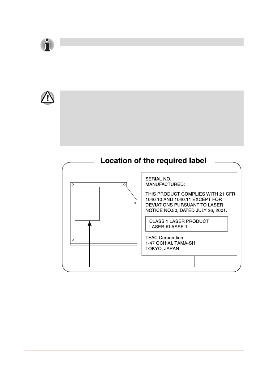
TEAC
DVD Super Multi drive DV-W28S-VTJ/DV-W28S-VTK
■ The DVD Super Multi drive model employs a laser system. To ensure
proper use of this product, please read this instruction manual carefully
and retain for future reference. Should the unit ever require
maintenance, contact an authorized service location.
■ Use of controls, adjustments or the performance of procedures other
than those specified may result in hazardous radiation exposure.
■ To prevent direct exposure to the laser beam, do not try to open the
enclosure.
L670/L675/L670D/L675D
User’s Manual xi
Page 11
Panasonic
DVD Super Multi drive UJ890A/UJ890E
■ The DVD Super Multi drive model employs a laser system. To ensure
proper use of this product, please read this instruction manual carefully
and retain for future reference. Should the unit ever require
maintenance, contact an authorized service location.
■ Use of controls, adjustments or the performance of procedures other
than those specified may result in hazardous radiation exposure.
■ To prevent direct exposure to the laser beam, do not try to open the
enclosure.
L670/L675/L670D/L675D
User’s Manual xii
Page 12
HLDS
DVD Super Multi drive GT30N/GT30F
■ The DVD Super Multi drive model employs a laser system. To ensure
proper use of this product, please read this instruction manual carefully
and retain for future reference. Should the unit ever require
maintenance, contact an authorized service location.
■ Use of controls, adjustments or the performance of procedures other
than those specified may result in hazardous radiation exposure.
■ To prevent direct exposure to the laser beam, do not try to open the
enclosure.
L670/L675/L670D/L675D
Hitachi-LG Data Storage, Inc.
22-23,KAIGAN 3-CHOME,
MINATO-KU,TOKYO,108-0022
JAPAN
User’s Manual xiii
Page 13
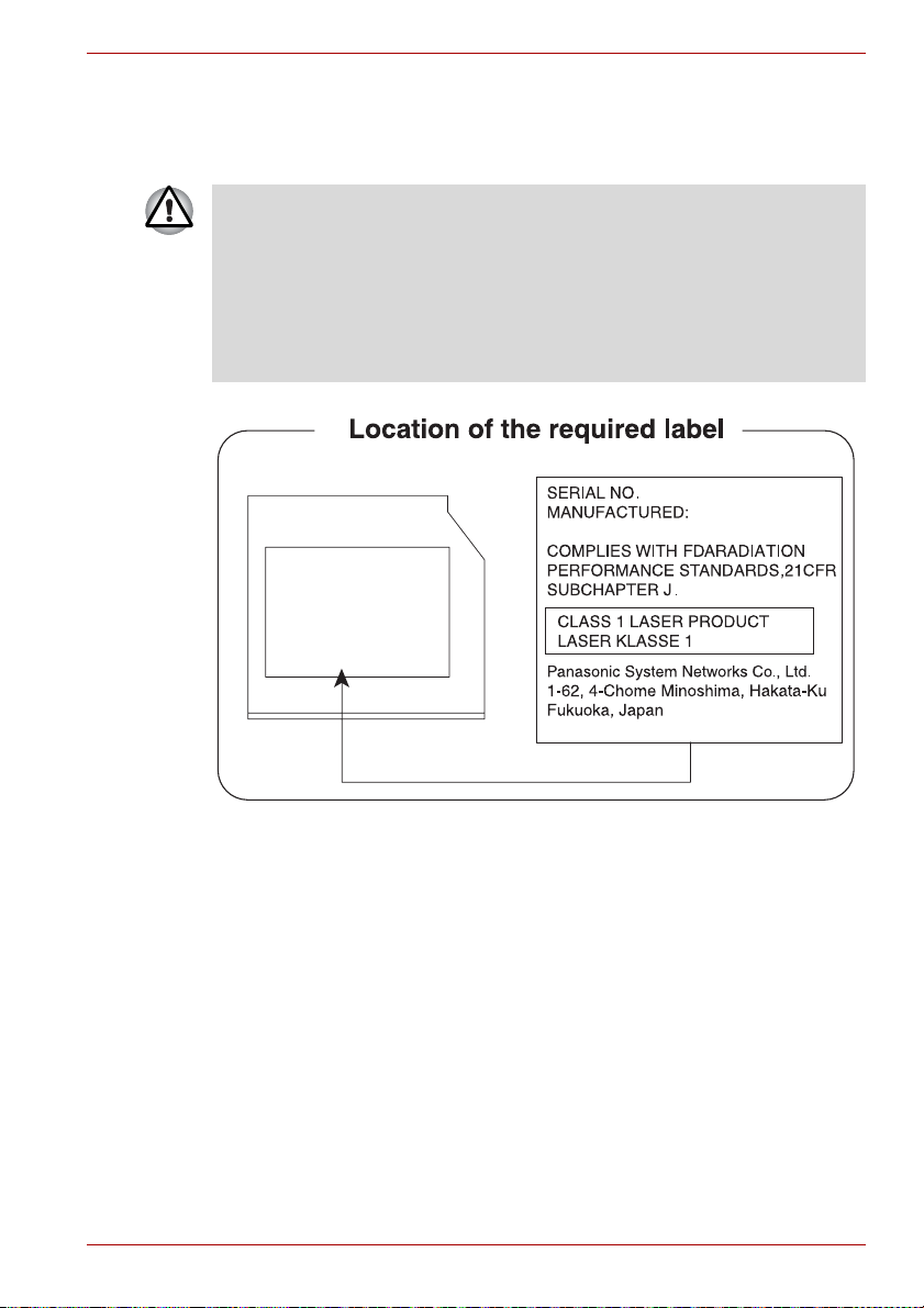
Panasonic
BD Writer drive UJ240E
■ The BD Writer drive employs a laser system. To ensure proper use of
this product, please read this instruction manual carefully and retain for
future reference. Should the unit ever require maintenance, contact an
authorized service location.
■ Use of controls, adjustments or the performance of procedures other
than those specified may result in hazardous radiation exposure.
■ To prevent direct exposure to the laser beam, do not try to open the
enclosure.
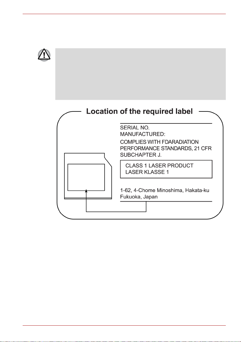
Location of the required label
L670/L675/L670D/L675D
COMPLIES WITHFDA RADIATION
PERFORMANCE STANDARDS, 21
CFR SUBCHAPTER J
MANUFACTURED
Panasonic System Networks Co., Ltd.
1-62, 4-Chome Minoshima Hakata-Ku
Fukuoka, Japan
User’s Manual xiv
Page 14
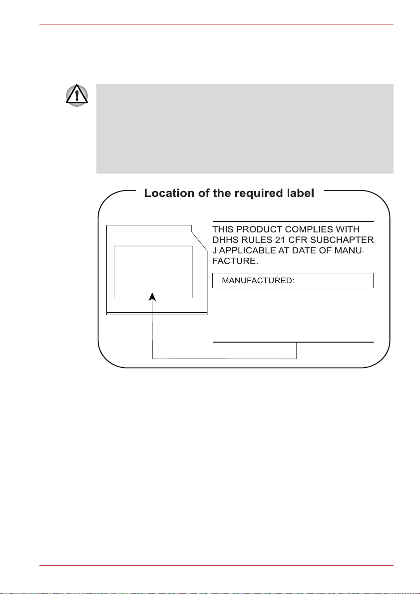
Panasonic
BD Combo drive UJ141E
■ The BD Combo/BD-R/RE drive employs a laser system. To ensure
proper use of this product, please read this instruction manual carefully
and retain for future reference. Should the unit ever require
maintenance, contact an authorized service location.
■ Use of controls, adjustments or the performance of procedures other
than those specified may result in hazardous radiation exposure.
■ To prevent direct exposure to the laser beam, do not try to open the
enclosure.
L670/L675/L670D/L675D
Panasonic System Networks Co., Ltd.
User’s Manual xv
Page 15

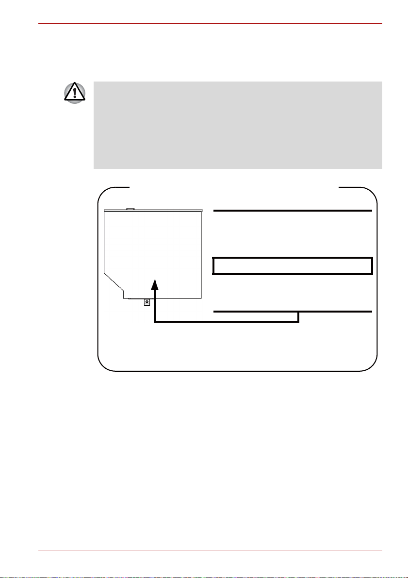
International precautions
L670/L675/L670D/L675D
CAUTION: This appliance contains a
laser system and is classified as a
"CLASS 1 LASER PRODUCT." To use
this model properly, read the instruction
manual carefully and keep this manual for
your future reference. In case of any
trouble with this model, please contact
your nearest "AUTHORIZED service
station." To prevent direct exposure to the
laser beam, do not try to open the
enclosure.
CAUTION: USE OF CONTROLS OR
ADJUSTMENTS OR PERFORMANCE
OF PROCEDURES OTHER THAN
THOSE SPECIFIED IN THE OWNER’S
MANUAL MAY RESULT IN HAZARDOUS
RADIATION EXPOSURE.
User’s Manual xvi
Page 16

Preface
Congratulations on your purchase of the L670/L675/L670D/L675D
computer. This powerful notebook computer provides excellent expansion
capability, includes multimedia functionality, and is designed to provide
years of reliable, high-performance computing.
This manual tells how to set up and begin using your computer. It also
provides detailed information on configuring your computer, basic
operations and care, using optional devices and troubleshooting.
If you are a new user of computers or if you’re new to portable computing,
first read over the Chapter 1, Getting Started and Chapter 3, Hardware,
Utilities and Options chapters to familiarize yourself with the computer’s
features, components and accessory devices. Then read Chapter 1,
Getting Started for step-by-step instructions on setting up your computer.
If you are an experienced computer user, please continue reading the
preface to learn how this manual is organized, then become acquainted
with this manual by browsing through its pages. Be sure to read the Special
features section in Chapter 3, Hardware, Utilities and Options to learn
about features that are uncommon or unique to this computer, as well as
the section on Chapter 7, HW Setup, to understand how to setup and
configure these features.
Read Chapter 3, Hardware, Utilities and Options if connecting optional
products or external devices.
L670/L675/L670D/L675D
Conventions
This manual uses the following formats to describe, identify, and highlight
terms and operating procedures.
Abbreviations
On first appearance, and whenever necessary for clarity, abbreviations are
enclosed in parentheses following their definition. For example: Read Only
Memory (ROM). Acronyms are also defined in the Glossary.
User’s Manual xxii
Page 17
L670/L675/L670D/L675D
Icons
Icons identify ports, dials, and other parts of your computer. The indicator
panel also uses icons to identify the components it is providing information
on.
Keys
The keyboard keys are used in the text to describe many computer
operations. A distinctive typeface identifies the key top symbols as they
appear on the keyboard. For example, ENTER identifies the ENTER key.
Key operation
Some operations require you to simultaneously use two or more keys. We
identify such operations by the key top symbols separated by a plus sign
(+). For example, CTRL + C means you must hold down CTRL and at the
same time press C. If three keys are used, hold down the first two and at
the same time press the third.
ABC When procedures require an action such as
clicking an icon or entering text, the icon’s name
or the text you are to type in is represented in the
type face you see to the left.
Display
ABC
Names of windows or icons or text generated by
the computer that appears on its display screen
is presented in the type face you see to the left.
Messages
Messages are used in this manual to bring important information to your
attention. Each type of message is identified as shown below.
Pay attention! A caution informs you that improper use of equipment or
failure to follow instructions may cause data loss or damage your
equipment.
Please read. A note is a hint or advice that helps you make best use of
your equipment.
Indicates a potentially hazardous situation, which could result in death or
serious injury, if you do not follow instructions.
User’s Manual xxiii
Page 18

Terminology
This term is defined in this document as follows:
Start The word "Start" refers to the " " button in
Windows 7.
HDD or Hard disk
drive
Some models are equipped with a "Solid State
Drive (SSD)" instead of a hard disk drive.
In this manual, the word "HDD" or "Hard disk
drive" also refers to the SSD unless otherwise
stated.
L670/L675/L670D/L675D
User’s Manual xxiv
Page 19

General Precautions
TOSHIBA computers are designed to optimize safety, minimize strain and
withstand the rigors of portability. However, certain precautions should be
observed to further reduce the risk of personal injury or damage to the
computer.
Be certain to read the general precautions below and to note the cautions
included in the text of the manual.
Provide adequate ventilation
■
Always make sure your computer and AC adaptor have adequate
ventilation and are protected from overheating when the power is turned
on or when an AC adaptor is connected to a power outlet (even if your
computer is in Sleep Mode). In this condition, observe the following:
■ Never cover your computer or AC adaptor with any object.
■ Never place your computer or AC adaptor near a heat source, such
as anelectric blanket or heater.
■ Never cover or block the air vents including those located at the
base of the computer.
■ Always operate your computer on a hard flat surface. Using your
computer on a carpet or other soft material can block the vents.
■ Always provide sufficient space around the computer.
■ Overheating your computer or AC adaptor could cause system failure,
computer or AC adaptor damage or a fire, possibly resulting in serious
injury.
L670/L675/L670D/L675D
User’s Manual xxv
Page 20

Creating a computer-friendly environment
Place the computer on a flat surface that is large enough for the computer
and any other items you are using, such as a printer.
Leave enough space around the computer and other equipment to provide
adequate ventilation. Otherwise, they may overheat.
To keep your computer in prime operating condition, protect your work area
from:
■ Dust, moisture, and direct sunlight.
■ Equipment that generates a strong electromagnetic field, such as
stereo speakers (other than speakers that are connected to the
computer) or speakerphones.
■ Rapid changes in temperature or humidity and sources of temperature
change such as air conditioner vents or heaters.
■ Extreme heat, cold, or humidity.
■ Liquids and corrosive chemicals.
Stress injury
Carefully read the Instruction Manual for Safety and Comfort. It contains
information on the prevention of stress injuries to your hands and wrists
that can be caused by extensive keyboard use. Instruction Manual for
Safety and Comfort also includes information on work space design,
posture and lighting that can help reduce physical stress.
L670/L675/L670D/L675D
Heat injury
■ Avoid prolonged physical contact with the computer. If the computer is
used for long periods, its surface can become very warm. While the
temperature will not feel hot to the touch, if you maintain physical
contact with the computer for a long time, for example if you rest the
computer on your lap or if you keep your hands on the palm rest, your
skin might suffer a low-heat injury.
■ If the computer has been used for a long time, avoid direct contact with
the metal plate supporting the various interface ports as this can
become hot.
■ The surface of the AC adaptor can become hot when in use but this
condition does not indicate a malfunction. If you need to transport the
AC adaptor, you should disconnect it and let it cool before moving it.
■ Do not lay the AC adaptor on a material that is sensitive to heat as the
material could become damaged.
Pressure or impact damage
Do not apply heavy pressure to the computer or subject it to any form of
strong impact as this can damage the computer's components or otherwise
cause it to malfunction.
User’s Manual xxvi
Page 21

Mobile phones
Please be aware that the use of mobile phones can interfere with the audio
system. The operation of the computer will not be impaired in any way, but
it is recommended that a minimum distance of 30cm is maintained between
the computer and a mobile phone that is in use.
Instruction Manual for Safety and Comfort
All important information on the safe and proper use of this computer is
described in the enclosed Instruction Manual for Safety and Comfort. Be
sure to read it before using the computer.
L670/L675/L670D/L675D
User’s Manual xxvii
Page 22

Getting Started
This chapter provides an equipment checklist, and basic information to start
using your computer.
Some of the features described in this manual may not function properly if
you use an operating system that was not pre-installed by TOSHIBA.
Equipment checklist
Carefully unpack your computer, taking care to save the box and packaging
materials for future use.
Hardware
Check to make sure you have all the following items:
■ L670/L675/L670D/L675D Portable Personal Computer
■ AC adaptor and power cord (2-pin plug or 3-pin plug)
Getting Started
Chapter 1
Documentation
■ L670/L675/L670D/L675D User’s Manual
■ L670/L675/L670D/L675D Quickstart
■ Instruction Manual for Safety and Comfort (included in User’s
Manual)
■ Warranty information
If any of the items are missing or damaged, contact your dealer
immediately.
Software
The following Windows® operating system and utility software are preinstalled.
■ Windows 7
■ TOSHIBA Value Added Package
■ TOSHIBA HW Setup
■ TOSHIBA Flash Cards Support Utility
User’s Manual 1-1
Page 23

■ TOSHIBA Supervisor Password
■ Corel DVD MovieFactory for TOSHIBA (Is preinstalled with some
■ WinDVD BD for TOSHIBA (Is preinstalled with some models)
■ TOSHIBA Recovery Media Creator
■ TOSHIBA DVD PLAYER (Is preinstalled with some models)
■ TOSHIBA Assist
■ TOSHIBA ConfigFree™
■ TOSHIBA Disc Creator
■ TOSHIBA Face Recognition
■ TOSHIBA Bulletin Board
■ TOSHIBA ReelTime
■ TOSHIBA eco Utility
■ Windows Mobility Center
■ Online Manual
Getting Started
■ All users should be sure to read the section Starting up for the first
time.
■ Be sure to read the enclosed Instruction Manual for Safety and
Comfort for information on the safe and proper use of this computer. It
is intended to help you be more comfortable and productive while
using a notebook computer. By following the recommendations in it
you may reduce your chance of developing a painful or disabling injury
to your hand, arms, shoulders or neck.
This section provides basic information to start using your computer. It
covers the following topics:
■ Connecting the AC adaptor
■ Opening the display
■ Turning on the power
■ Starting up for the first time
■ Turning off the power
■ Restarting the computer
■ System Recovery Options and Rstoring the pre-installed software
Getting Started
models)
User’s Manual 1-2
Page 24

■ Use a virus-check program and make sure it is updated regularly.
■ Never format storage media without checking its content - formatting
destroys all stored data.
■ It is a good idea to periodically back up the internal hard disk drive or
other main storage device to external media. General storage media is
not durable or stable over long periods of time and under certain
conditions may result in data loss.
■ Before you install a device or application, save any data in memory to
the hard disk drive or other storage media. Failure to do so may result
in the loss of data.
Connecting the AC adaptor
Attach the AC adaptor when you need to charge the battery or you want to
operate from AC power. It is also the fastest way to get started, because
the battery pack will need to be charged before you can operate from
battery power.
The AC adaptor can be connected to any power source supplying from
90 to 264 volts and 47 to 63 hertz. For details on using the AC adaptor to
charge the battery pack, refer to Chapter 6, Power and Power-Up Modes.
Getting Started
User’s Manual 1-3
Page 25

Getting Started
■ Always use the TOSHIBA AC adaptor that was included with your
computer, or use AC adaptors specified by TOSHIBA to avoid any risk
of fire or other damage to the computer. Use of an incompatible AC
adaptor could cause fire or damage to the computer possibly resulting
in serious injury. TOSHIBA assumes no liability for any damage
caused by use of an incompatible adaptor.
■ Never plug the AC adaptor into a power source that does not
correspond to both the voltage and the frequency specified on the
regulatory label of the unit. Failure to do so could result in a fire or
electric shock, possibly resulting in serious injury.
■ Always use or purchase power cables that comply with the legal
voltage and frequency specifications and requirements in the country
of use. Failure to do so could result in a fire or electric shock, possibly
resulting in serious injury.
■ The supplied power cord conforms to safety rules and regulations in
the region the product is bought and should not be used outside this
region. For use in other regions, please buy power cords that conform
to safety rules and regulations in the particular region.
■ Do not use a 3-pin to 2-pin conversion plug.
■ When you connect the AC adaptor to the computer, always follow the
steps in the exact order as described in the User’s Manual. Connecting
the power cable to a live electrical outlet should be the last step
otherwise the adaptor DC output plug could hold an electrical charge
and cause an electrical shock or minor bodily injury when touched. As
a general safety precaution, avoid touching any metal parts.
■ Never place your computer or AC adaptor on a wooden surface,
furniture, or any other surface that could be marred by exposure to
heat since the computer base and AC adaptor's surface increase in
temperature during normal use.
■ Always place your computer or AC adaptor on a flat and hard surface
that is resistant to heat damage.
Refer to the enclosed Instruction Manual for Safety and Comfort for
detailed precautions and handling instructions.
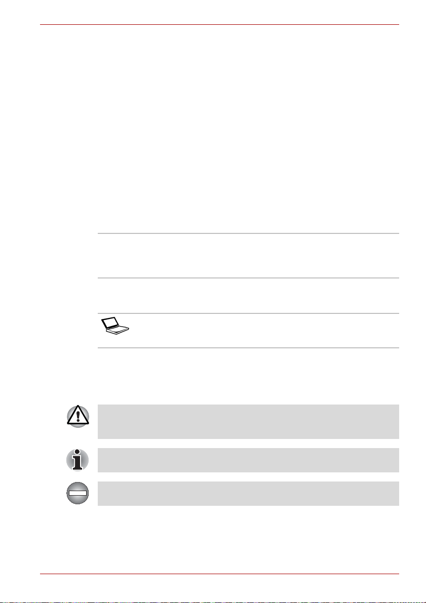
1. Connect the power cord to the AC adaptor.
Connecting the power cord to the AC adaptor (2-pin plug)
User’s Manual 1-4
Page 26
Getting Started
Connecting the power cord to the AC adaptor (3-pin plug)
Either a 2-pin or 3-pin adaptor/cord will be included with the computer
depending on the model.
2. Connect the AC adaptor’s DC output plug to the DC IN 19V jack on the
left side of the computer.
1
2
1. DC IN 19V jack 2. DC output plug
Connecting the DC output plug to the computer
3. Plug the power cord into a live wall outlet - the Battery and DC IN
indicators on the front of the computer should glow.
User’s Manual 1-5
Page 27
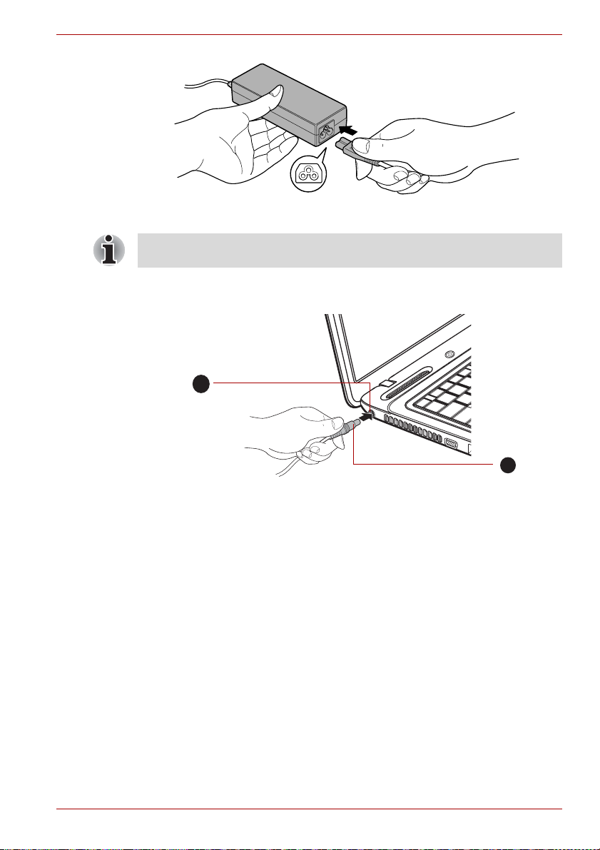
Opening the display
The display panel can be opened to a wide range of angles for optimal
viewing.
While holding down the palm rest with one hand so that the main body of
the computer is not raised, slowly lift the display panel - this will allow the
angle of the display panel to be adjusted to provide optimum clarity.
1. Display panel
Opening the display panel
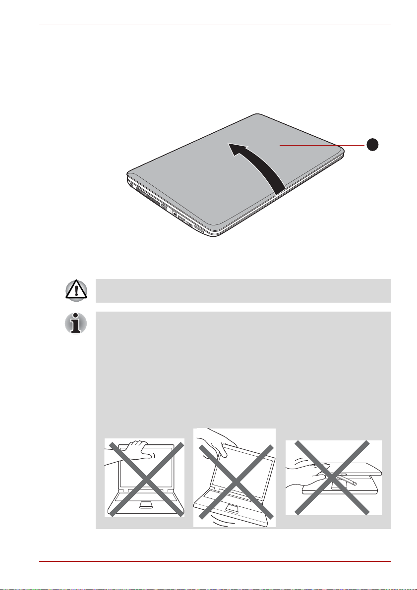
Use reasonable care when opening and closing the display panel.
Opening it vigorously or slamming it shut could damage the computer.
Getting Started
1
■ Be careful not to open the display panel too far as this could put stress
on the display panel’s hinges and cause damage.
■ Do not press or push on the display panel.
■ Do not lift the computer by the display panel.
■ Do not close the display panel with pens or any other objects left in
between the display panel and the keyboard.
■ When opening or closing the display panel, place one hand on the
palm rest to hold the computer in place and use the other hand to
slowly open or close the display panel (Do not use excessive force
when opening or closing the display panel).
User’s Manual 1-6
Page 28
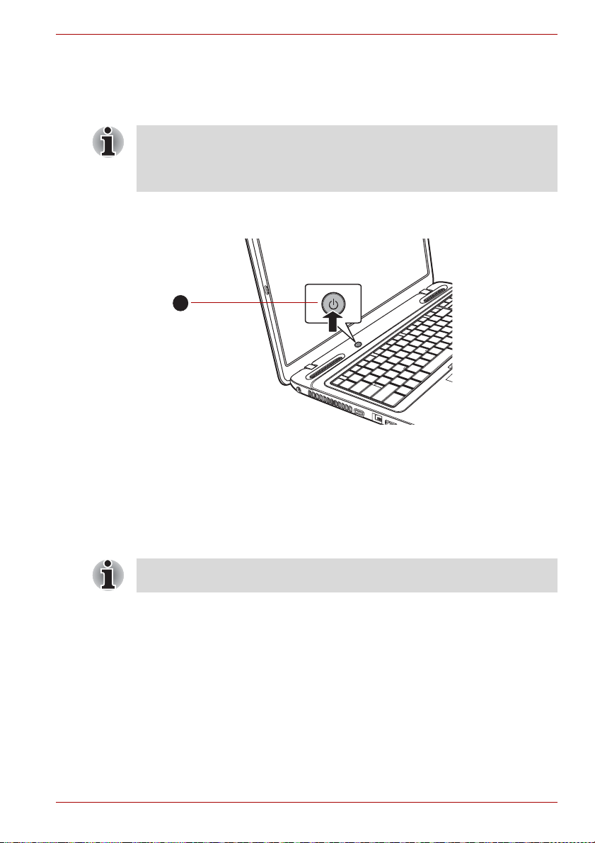
Turning on the power
This section describes how to turn on the power - the Power indicator will
then indicate the status. Please refer to the Monitoring of power condition
section in Chapter 6, Power and Power-Up Modes for more information.
■ After you turn on the power for the first time, do not turn it off until you
have set up the operating system. Please refer to the section Starting
up for the first time for more information.
■ Volume cannot be adjusted during Windows Setup.
1. Open the display panel.
2. Press and hold the computer's power button for one or two seconds.
1
Getting Started
1. Power button
Turning on the power
Starting up for the first time
The Windows 7 Startup Screen will be the first screen displayed when you
turn on the power. Follow the on-screen instructions on each screen in
order to properly install the operating system.
When it is displayed, be sure to read the Software License Terms
carefully.
User’s Manual 1-7
Page 29

Turning off the power
The power can be turned off in one of three modes, either Shut Down
Mode, Hibernation Mode or Sleep Mode.
Shut Down Mode
When you turn off the power in Shut Down Mode no data will be saved and
the computer will boot to the operating system's main screen the next time
it is turned on.
1. If you have entered data, either save it to the hard disk drive or to other
storage media.
2. Make sure all disk/disc activity has stopped before removing the
CD/DVD or floppy diskette.
■ Make sure the Hard Disk Drive/Optical Disc Drive indicators are off.
If you turn off the power while a disk (disc) is being accessed, you may
lose data or damage the disk.
■ Never turn off the power while an application is running. Doing so
could cause loss of data.
■ Never turn off the power, disconnect an external storage device or
remove storage media during data read/write. Doing so can cause
data loss.
3. Click Start.
4. Click the Shut down button ( ).
5. Turn off any peripheral devices connected to your computer.
Do not turn the computer or peripheral devices back on immediately - wait
a short period to avoid any potential damage.
Getting Started
Sleep Mode
If you have to interrupt your work, you are able to turn off the power without
exiting from your software by placing the computer into Sleep Mode. In this
mode data is maintained in the computer's main memory so that when you
turn on the power again, you can continue working right where you left off.
When you have to turn off your computer aboard an aircraft or in places
where electronic devices are regulated or controlled, always completely
shut down the computer. This includes turning off any wireless
communication switches or devices, and canceling settings that reactivate
the computer automatically, such as a timer recording function. Failure to
completely shut down the computer in this way could allow the operating
system to reactivate and run pre-programmed tasks or preserve unsaved
data, which could interfere with aviation or other systems, possibly
causing serious injury.
User’s Manual 1-8
Page 30

Getting Started
■ Before entering Sleep Mode, be sure to save your data.
■ Do not install or remove a memory module while the computer is in
Sleep Mode. The computer or the memory module could be damaged.
■ Do not remove the battery pack while the computer is in Sleep Mode
(unless the computer is connected to an AC power source). Data in
memory could be lost.
■ When the AC adaptor is connected, the computer will go into Sleep
Mode according to the settings in the Power Options (to access it,
Start Control Panel System and Security Power Options).
■ To restore the operation of the computer from Sleep Mode, press and
hold the power button or any key on the keyboard for a short amount of
time. Please note that keyboard keys can only be used if the Wake-up
on Keyboard option is enabled within the HW Setup utility.
■ If the computer enters Sleep Mode while a network application is
active, the application might not be restored when the computer is next
turned on and the system returns from Sleep Mode.
■ To prevent the computer from automatically entering Sleep Mode,
disable Sleep Mode within the Power Options (to access it, Start
Control Panel System and Security Power Options).
■ To use the Hybrid Sleep function, configure it in the Power Options.
Benefits of Sleep Mode
The Sleep Mode feature provides the following benefits:
■ Restores the previous working environment more rapidly than does the
Hibernation Mode feature.
■ Saves power by shutting down the system when the computer receives
no input or hardware access for the time period set by the System
Sleep Mode feature.
■ Allows the use of the panel power off feature.
Executing Sleep Mode
You can also enable Sleep Mode by pressing FN + F3 - please refer to
Chapter 5,The Keyboard, for further details.
You can enter Sleep Mode in one of three ways:
■ Click Start, point to the arrow icon ( ) and then select
Sleep from the menu.
■ Close the display panel. Please note that this feature must be enabled
within the Power Options (to access it, click Start Control Panel
System and Security Power Options).
■ Press the power button. Please note that this feature must be enabled
within the Power Options (to access it, click Start Control Panel
System and Security Power Options).
User’s Manual 1-9
Page 31

Getting Started
When you turn the power back on, you can continue where you left when
you shut down the computer.
■ When the computer is in Sleep Mode, the power indicator will blink
amber.
■ If you are operating the computer on battery power, you can lengthen
the overall operating time by turning it off into Hibernation Mode Sleep Mode will consume more power while the computer is off.
Sleep Mode limitations
Sleep Mode will not function under the following conditions:
■ Power is turned back on immediately after shutting down.
■ Memory circuits are exposed to static electricity or electrical noise.
Hibernation Mode
The Hibernation Mode feature saves the contents of memory to the hard
disk drive when the computer is turned off so that, the next time it is turned
on, the previous state is restored. Please note that the Hibernation Mode
feature does not save the status of any peripheral devices connected to the
computer.
■ Save your data. While entering Hibernation Mode, the computer saves
the contents of memory to the hard disk drive. However, for safety
sake, it is best to save your data manually.
■ Data will be lost if you remove the battery or disconnect the AC
adaptor before the save is completed. Wait for the Hard Disk Drive
indicator to go out.
■ Do not install or remove a memory module while the computer is in
Hibernation Mode. Data will be lost.
Benefits of Hibernation Mode
The Hibernation Mode feature provides the following benefits:
■ Saves data to the hard disk drive when the computer automatically
shuts down because of a low battery condition.
■ You can return to your previous working environment immediately when
you turn on the computer.
■ Saves power by shutting down the system when the computer receives
no input or hardware access for the time period set by the System
Hibernate feature.
■ Allows the use of the panel power off feature.
User’s Manual 1-10
Page 32

Getting Started
Starting Hibernation Mode
You can also enable Hibernation Mode by pressing FN + F4 - please refer
to Chapter 5, The Keyboard, for further details.
To enter Hibernation Mode, follow the steps below.
1. Click Start.
2. Point to the arrow icon ( ) and then select Hibernate
from the menu.
Automatic Hibernation Mode
The computer can be configured to enter Hibernation Mode automatically
when you press the power button or close the lid. In order to define these
settings, you can follow the steps as described below:
1. Click Start and click the Control Panel.
2. Click System and Security and click Power Options.
3. Click Choose what the power button does or Choose what closing
the lid does.
4. Enable the desired Hibernation Mode settings for When I press the
power button and When I close the lid.
5. Click the Save changes button.
Data save in Hibernation Mode
When you turn off the power in Hibernation Mode, the computer will take a
moment to save the current data in memory to the hard disk drive. During
this time, the Hard Disk Drive indicator will glow.
After you turn off the computer, and the content of memory has been saved
to the hard disk drive, turn off the power to any peripheral devices.
Do not turn the computer or devices back on immediately. Wait a moment
to let all capacitors fully discharge.
Restarting the computer
Certain conditions require that you reset the computer, for example if:
■ You change certain computer settings.
■ An error occurs and the computer does not respond to your keyboard
commands.
If you need to restart the computer, there are three ways this can be achieved:
■ Click Start, point to the arrow icon ( ) and then select
Restart from the menu.
■ Press CTRL, ALT and DEL simultaneously (once) to display the menu
window, then select Restart from the Shut down options.
■ Press the power button and hold it down for four seconds. Once the
computer has turned itself off, wait between ten and fifteen seconds
before turning the power on again by pressing the power button.
User’s Manual 1-11
Page 33

Getting Started
System Recovery Options and Restoring the pre-installed software
There is a hidden partition allocated on the hard disk drive for the System
Recovery Options.
This partition stores files which can be used to repair the system in the
event of a problem.
The System Recovery Options feature will be unusable if this partition is
deleted.
System Recovery Options
The System Recovery Options feature is installed on the hard disk when
shipped from the factory. The System Recovery Options menu includes
tools to repair startup problems, run diagnostics or restore the system.
See the Windows Help and Support content for more information about
Startup Repair.
The System Recovery Options can also be run manually to repair
problems.
The procedure is as follows. Follow the instructions shown on the onscreen menu.
1. Turn off the computer.
2. While holding the F8 key, turn on the computer.
3. The Advanced Boot Options menu will be displayed.
Use the arrow keys to select Repair Your Computer and press
ENTER.
4. Follow the on-screen instructions.
Check your Windows® manual for more information on backing up your
system (including the system image backup feature).
Restoring the pre-installed software
Depending on the model you purchased, different ways for restoring the
pre-installed software are offered:
■ Creating optical Recovery Media and restoring the pre-installed
software from them
■ Restoring the pre-installed software from the Recovery hard disk drive
■ Ordering Recovery Media from TOSHIBA and restoring the pre-
installed software from them*
* Please note that this service is not free-of-charge.
User’s Manual 1-12
Page 34

Creating Recovery Media
This section describes how to create Recovery Media.
■ Be sure to connect the AC adaptor when you create Recovery Media.
■ Be sure to close all other software programs except the Recovery
Media Creator.
■ Do not run software such as screen savers which can put a heavy load
on the CPU.
■ Operate the computer at full power.
■ Do not use power-saving features.
■ Do not write to the media when the virus check software is running.
Wait for it to finish, then disable virus detection programs including any
software that checks files automatically in the background.
■ Do not use utilities, including those intended to enhance hard disk
drive access speed. They may cause unstable operation and damage
data.
■ Do not shut down/log off or Sleep/Hibernate while writing or rewriting
the media.
■ Set the computer on a level surface and avoid places subjected to
vibrations such as airplanes, trains, or cars.
■ Do not use on an unstable surface such as a stand.
A recovery image of the software on your computer is stored on the hard
disk drive, and can be copied to either CD, DVD or USB Flash Memory by
using the following steps:
1. Select either blank CD, DVD or USB Flash Memory.
The application will allow you to choose from a variety of different media
onto which the recovery image can be copied including CD-R, CD-RW,
DVD-R, DVD-R DL, DVD-RW, DVD+R, DVD+R DL, DVD+RW and USB
Flash Memory.
■ Please note that some of the above media may not be compatible with
the optical disc drive installed into your computer. You should therefore
verify the optical disc drive supports the blank media you have chosen
before proceeding.
■ USB Flash Memory will be formatted and all the data in the USB Flash
Memory will be lost when proceeding.
2. Turn on your computer and allow it to load the Windows 7 operating
system from the hard disk drive as normal.
3. Insert the media into the computer.
■ Insert the first blank disc into the optical disc drive tray, or Insert the
USB Flash Memory into one available USB port
4. Double click the Recovery Media Creator icon on the Windows 7
desktop, or select the application from Start Menu.
5. After Recovery Media Creator starts, select the type of media and the
title you wish to copy, and then click the Create button.
Getting Started
User’s Manual 1-13
Page 35

Getting Started
Restoring the pre-installed software from the Recovery hard disk
drive
A portion of the total hard disk drive space is configured as a hidden
recovery partition. This partition stores files which can be used to restore
pre-installed software in the event of a problem.
If you subsequently set up your hard disk drive again, do not change,
delete or add partitions in a manner other than specified in the manual,
otherwise you may find that space for the required software is not available.
In addition, if you use a third-party partitioning program to reconfigure the
partitions on your hard disk drive, you may find that it becomes impossible
to setup your computer.
When the sound mute feature has been activated by pressing the
FN + ESC key, be sure to disable this to allow sounds to be heard before
starting the restore process. Please refer to Chapter 5,The Keyboard, for
further details.
You can not use System Recovery Options if restoring the pre-installed
software without System Recovery Options.
When you reinstall the Windows operating system, the hard disk will be
reformatted and all data will be lost.
1. Turn off your computer.
2. While holding down 0 (zero) key on the keyboard, turn on your
computer.
3. A menu will be displayed from which you should follow the on-screen
instructions.
Restoring the pre-installed software from your created Recovery
Media
If the pre-installed files are damaged, you are able to either use the
Recovery Media you have created or the hard disk drive recovery process
to restore the computer to the state it was in when you originally received it.
To perform this restoration, follow the steps below:
When the sound mute feature has been activated by pressing the
FN + ESC key, be sure to disable this to allow sounds to be heard before
starting the restore process. Please refer to Chapter 5, The Keyboard, for
further details.
You can not use System Recovery Options if restoring the pre-installed
software without System Recovery Options.
User’s Manual 1-14
Page 36

When you reinstall the Windows operating system, the hard disk will be
reformatted and all data will be lost.
1. Load the Recovery Media into the computer and turn off the computer's
power.
2. While holding down F12 key on the keyboard, turn on your computer when the TOSHIBA Leading Innovation >>> logo screen
appears, release the F12 key.
3. Use the up and down cursor key to select the appropriate option from
the menu according to your actual recovery media. Please refer to the
Boot Priority section in Chapter 7, HW Setup for further information.
4. A menu will be displayed from which you should follow the on-screen
instructions.
When drivers/utilities are installed, you can setup the respective
drivers/utilities from the following place. To open the setup files, Click
Start All Programs TOSHIBA Applications and Drivers.
Ordering Recovery Media from TOSHIBA*
You can order Product Recovery Media for your notebook from the
TOSHIBA Europe Backup Media Online Shop.
* Please note that this service is not free-of-charge.
1. Visit https://backupmedia.toshiba.eu on the Internet.
2. Follow the on-screen instructions.
You will receive your Recovery Discs within two weeks after placing your
order.
Getting Started
User’s Manual 1-15
Page 37

The Grand Tour
This chapter identifies the various components of the computer - it is
recommended that you become familiar with each before you operate the
computer.
Legal Footnote (Non-applicable Icons)
For more information regarding Non-applicable Icons, please refer to
Appendix G, Legal Footnotes.
Please handle your computer carefully to avoid scratching or damaging
the surface.
Front with the display closed
The following figure shows the computer’s front with its display panel in the
closed position.
The Grand Tour
Chapter 2
1
1. System indicators
Front of the computer with display panel closed
Product appearance depends on the model you purchased.
System indicators These LED indicators allow you to monitor the
User’s Manual 2-1
status of various computer functions and are
described in more detail within the System
indicators section.
Page 38

Left side
The Grand Tour
The following figure shows the computer’s left side.
1
1. DC IN 19V jack 5. eSATA/USB combo port
2. Cooling vents 6. HDMI out port
3. External monitor port 7. Bridge media slot
4. LAN jack
2 3
The left side of the computer
4 5 6 7
DC IN 19V jack The AC adaptor connects to this jack in order to
power the computer and charge its internal
batteries. Please note that you should only use
the model of AC adaptor supplied with the
computer at the time of purchase - using the
wrong AC adaptor can cause damage to the
computer.
Cooling vents The cooling vents help keep the processor from
overheating.
Do not block the cooling vents. Keep foreign metal objects, such as
screws, staples and paper clips, out of the cooling vents. Foreign metal
objects can create a short circuit, which can cause damage and fire,
possibly resulting in serious injury.
External monitor port This 15-pin, analog VGA port allows you to
connect an external monitor to the computer.
LAN jack This jack lets you connect to a LAN. The adaptor
has built-in support for Ethernet LAN
(10 megabits per second, 10BASE-T), Fast
Ethernet LAN (100 megabits per second,
100BASE-TX). Some models are equipped with
a Gigabit Ethernet LAN (1000 megabits per
second, 1000BASE-T). Refer to Chapter 4,
Operating Basics, for details.
User’s Manual 2-2
Page 39

The Grand Tour
■ Do not connect any cable other than a LAN cable to the LAN jack. It
could cause damage or malfunction.
■ Do not connect the LAN cable to a power supply. It could cause
damage or malfunction.
eSATA/USB combo
port
One eSATA/USB combo port, which complies to
the USB 2.0 standard, is provided on the left
hand side of the computer. This port has eSATA
(External Serial ATA) function. Some models are
equipped with a eSATA/USB combo port.
Keep foreign metal objects, such as screws, staples and paper clips, out of
the eSATA/USB combo port. Foreign metal objects can create a short
circuit, which can cause damage and fire, possibly resulting in serious
injury.
Please note that it is not possible to confirm the operation of all functions
of all USB devices that are available. In view of this it may be noted that
some functions associated with a specific device might not operate
properly.
HDMI out port HDMI out port can connect with a Type A
connector HDMI cable. It allows you to send
video and audio signals.
Bridge media slot This slot lets you insert an
SD™/SDHC™/SDXC™ memory card,
miniSD™/microSD™ Card, Memory Stick
®
(PRO™), and MultiMediaCard™. Refer to the
Optional devices section in Chapter 3, Hardware,
Utilities and Options.
Keep foreign metal objects, such as screws, staples and paper clips, out of
the Bridge media slot. Foreign metal objects can create a short circuit,
which can cause damage and fire, possibly resulting in serious injury.
User’s Manual 2-3
Page 40
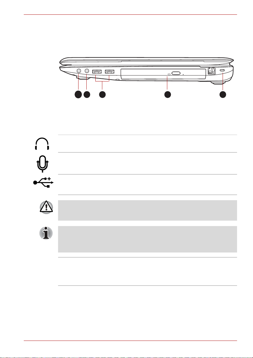
Right side
The Grand Tour
The following figure shows the computer’s right side.
2 43 6
1
1. Headphone jack 4. Optical disc drive
2. Microphone jack 5. Security lock slot
3. Universal Serial Bus (USB 2.0) ports
The right side of the computer
Headphone jack A 3.5 mm mini headphone jack enables
connection of stereo headphones.
Microphone jack A 3.5 mm mini microphone jack enables
connection of a three-conductor mini jack for
monaural microphone input.
Universal Serial Bus
(USB 2.0) ports
Two Universal Serial Bus ports, which comply to
the USB 2.0 standard, are provided on the right
hand side of the computer.
Keep foreign metal objects, such as screws, staples and paper clips, out of
the USB connectors. Foreign metal objects can create a short circuit,
which can cause damage and fire, possibly resulting in serious injury.
Please note that it is not possible to confirm the operation of all functions
of all USB devices that are available. In view of this it may be noted that
some functions associated with a specific device might not operate
properly.
Optical disc drive The computer is configured with a DVD Super
Multi drive, a BD Writer drive or BD Combo drive.
The full-size drive provides high-performance
execution of CD/DVD/BD-ROM-based programs.
User’s Manual 2-4
Page 41
The Grand Tour
■ Connection to any communication line other than an analog phone line
could cause a PC system failure.
■ Connect the built-in modem only to ordinary analog phone lines.
■ Never connect the built-in modem to a digital line (ISDN).
■ Never connect the built-in modem to the digital connector on a
public telephone or to a digital private branch exchange (PBX).
■ Never connect the built-in modem to a key telephone system for
residences or offices.
■ Avoid using your computer modem with the telephone cable
connected during an electrical storm. There may be a remote risk of
electric shock from lightning.
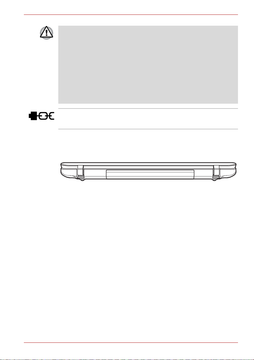
Back
Security lock slot A security cable can be attached to this slot and
then connected to a desk or other large object in
order to deter theft of the computer.
The following figure shows the computer’s back.
The back of the computer
User’s Manual 2-5
Page 42

Underside
The following figure shows the underside of the computer. You should
ensure that the display is closed before the computer is turned over to
avoid causing any damage.
The Grand Tour
1
1. Battery lock 4. Battery release latch
2. Memory module slot 5. Cooling vents
3. Battery pack
The underside of the computer
3 4
5
2
Battery lock Slide the battery lock to release the battery pack
ready for removal.
Memory module slot The memory module slot allows for the
installation, replacement and removal of
additional memory module.
Refer to the Additional memory module section
in Chapter 3, Hardware, Utilities and Options.
Battery pack The battery pack provides power to the computer
when the AC adaptor is not connected. For more
detailed information on the use and operation of
the battery pack please refer to Chapter 6, Power
and Power-Up Modes.
Battery release latch Slide and hold this latch into its "Unlock" position
in order to release the battery pack for removal.
For more detailed information on removing the
battery pack please refer to Chapter 6, Power
and Power-Up Modes.
Cooling vents The cooling vents help keep the processor from
overheating.
User’s Manual 2-6
Page 43

Do not block the cooling vents. Keep foreign metal objects, such as
screws, staples and paper clips, out of the cooling vents. Foreign metal
objects can create a short circuit, which can cause damage and fire,
possibly resulting in serious injury.
Front with the display open
This section shows the computer with the display panel open. In order to
open the display, lift the display panel up and position it at a comfortable
viewing angle for you.
4
1
5
6
The Grand Tour
23
1
7
8
11
7
8
12
9
10
1. Wireless LAN antennas (not shown) 8. Speakers
2. Web Camera 9. Keyboard
3. Web Camera LED 10. Touch Pad ON/OFF button
4. Microphone 11. Touch Pad
5. Display screen 12. Touch Pad control buttons
6. Power button 13. Bluetooth antenna (not shown)
7. Display hinges
13
The front of the computer with the display panel open
Product appearance depends on the model you purchased.
Wireless LAN
antennas
User’s Manual 2-7
Some computers in this series are equipped with
the Wireless LAN antennas.
Page 44

The Grand Tour
Web Camera Web Camera is a device that allows you to
record video or take photographs with your
computer. You can use it for video chatting or
video conferences using a communication tool
such as Windows Live Messenger. TOSHIBA
Web Camera Application will help you to add
various video effects to your video or
photograph.
Enables the transmission of video and use of
video chat via the internet using specialized
applications.
Some models are equipped with a Web Camera.
Please refer to the Web Camera section in
Chapter 4, Operating Basics.
Microphone A built-in microphone allows you to import and
record sounds for your application - please refer
to the Sound System section in Chapter 4,
Operating Basics for more information.Some
models are equipped with a built-in microphone.
Web Camera LED The Web Camera LED glows when the Web
Camera is operating.
Display screen Please be aware that, when the computer is
operating on the AC adaptor, the image
displayed on the internal screen will be
somewhat brighter than when it operates on
battery power. This difference in brightness
levels is intended to save power when operating
on batteries. For more information on the
computer's display, please refer to the Display
Controller and Video mode section in
Appendix B.
Power button Press this button to turn the computer's power on
and off.
Display hinges The display hinges allow the display panel to be
position at a variety of easy-to-view angles.
Stereo speakers The speakers emit sound generated by your
software as well as audio alarms, such as low
battery condition, generated by the system.
Keyboard Your computer may intergrated with two kinds of
keyboards: A4 size keyboard which provides the
embedded numeric overlay keys, dedicated
cursor control overlay keys, and and
Keys; full size keyboard which provides
dedicated numeric keys, dedicated cursor control
keys, and and Keys. The keyboard is
compatible with the IBM
®
enhanced keyboard.
Refer to Chapter 5, The Keyboard, for details.
User’s Manual 2-8
Page 45
The Grand Tour
Indicators
System indicators
Touch Pad ON/OFF
button
Touch Pad The Touch Pad located in the palm rest is used to
Touch Pad control
buttons
Bluetooth antenna Some computers in this series are equipped with
This section explains indicator functions.
LED system indicators next to their respective icons, glow when specific
computer operations are in progress.
Press this button to toggle the internal Touch Pad
enable/disable status. The status will be
emembered when resuming from Sleep and
Hibernation mode.
control the movement of the on-screen pointer.
For more information, please refer to the Using
the Touch Pad section in Chapter 4, Operating
Basics.
The control buttons located below the Touch Pad
allow you to select menu items or manipulate text
and graphics as designated by the on-screen
pointer.
a Bluetooth antenna.
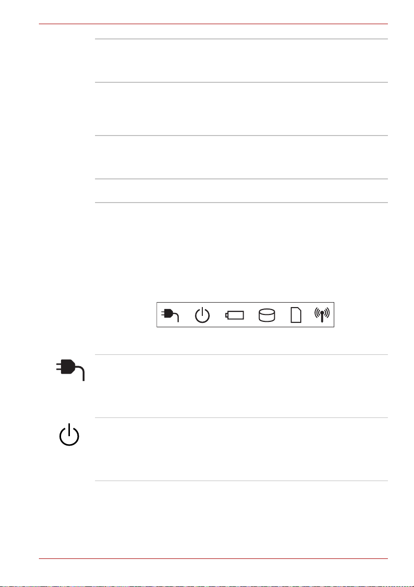
System indicators
DC IN The DC IN indicator normally glows white when
power is being correctly supplied from the AC
power adaptor. However, If the output voltage
from the adaptor is abnormal, or i f the computer's
power supply malfunctions, this indicator will
flash amber.
Power The Power indicator normally glows white when
User’s Manual 2-9
the computer is turned on. However, if you turn
the computer off into Sleep Mode, this indicator
will flash amber - approximately two second on,
two seconds off - both while the system is
shutting down and while it remains turned off.
Page 46

Battery The Battery indicator shows the condition of the
battery's charge - white indicates the battery is
fully charged, amber indicates the battery is
charging, and flashing amber indicates a low
battery condition. Please refer to Chapter 6,
Power and Power-Up Modes for more
information on this feature.
Hard Disk Drive/
Optical Disc Drive
The Hard Disk Drive/Optical Disc Drive
indicator glows white whenever the computer is
accessing the built-in hard disk drive, optical disc
drive or eSATA device.
Bridge media slot The Bridge media slot indicator glows white
when the computer is accessing the Bridge
media slot.
Wireless
communication
The Wireless communication indicator blinks
amber when the Bluetooth, Wireless LAN are
turned on.
Keyboard indicators
The following figure shows the positions of the CAPS LOCK indicator and
the NUM LOCK indicator.
The Grand Tour
2
1
1. CAPS LOCK indicator 2. NUM LOCK indicator
Keypad indicators
CAPS LOCK This indicator glows green when letter keys are
locked into their uppercase format.
NUM LOCK When the NUM LOCK indicator glows, you can
use the number keys on the keyboard for number
entry.
User’s Manual 2-10
Page 47

Optical disc drives
The computer is configured with a DVD Super Multi drive or BD writer or
BD-Combo drive. A Serial ATA interface controller is used for 12cm (4.72")
and 8cm (3.15") CD/DVD/BD operation. When the computer is accessing a
CD/DVD/BD, an indicator on the drive glows. For further information on
loading and unloading discs, please refer to the Writing CD/DVD/BD on
DVD Super Multi drives or BD Writer drives or BD Combo drives section in
Chapter 4, Operating Basics.
Region codes for BD media
BD is manufactured according to the specifications of three marketing
regions. When you purchase BD-Video, make sure it matches your player,
otherwise it will not play properly.
Code Region
A Canada, United States, Japan, Southeast Asia,
B Europe, Australia, New Zealand, Middle East,
C China, India, Russia, Mongolia, Indian
Region codes for DVD drives and media
DVD Super Multi drives and their associated media are manufactured
according to the specifications of six marketing regions. When you
purchase DVD-Video, make sure it matches your drive, otherwise it will not
play properly.
Code Region
1 Canada, United States
2 Japan, Europe, South Africa, Middle East
3 South East Asia, East Asia
4 Australia, New Zealand, Pacific Islands, Central
5 Russia, Indian Subcontinent, Africa, North
6 China
The Grand Tour
East Asia, Central America, South Americ
Africa
Subcontinent
America, South America, Caribbean
Korea,Mongolia
User’s Manual 2-11
Page 48

Writable discs
This section describes the types of writable CD/DVD/BD discs. Check the
specifications of your drive to see the types of discs it can write. Use
TOSHIBA Disc Creator to write compact discs. Please refer to Chapter 4,
Operating Basics for further information.
CDs
■ CD-R discs can be written only once. The recorded data cannot be
erased or changed.
■ CD-RW discs including multi speed CD-RW discs, high-speed CD-RW
discs and ultra-speed CD-RW discs can be recorded more than once.
DVDs
■ DVD-R, DVD+R, DVD-R (Dual Layer) and DVD+R (Double Layer) discs
can be written only once. The recorded data cannot be erased or
changed.
■ DVD-RW, DVD+RW and DVD-RAM discs can be recorded more than
once.
Some types and formats of DVD-R (Dual Layer) and DVD+R (Double
Layer) discs may be unreadable.
BDs
■ BD-R, BD-R(DL) discs can be written only once. The recorded data
cannot be erased or changed.
■ BD-RE, BD-RE(DL) discs can be recorded more than once.
The Grand Tour
User’s Manual 2-12
Page 49

BD-Writer drive
The full-size BD-Writer drive module lets you record data to writable
CD/DVD/BD discs as well as run either 12 cm (4.72") or 8 cm (3.15") for
Tray type CD/DVD/BDs without using an adaptor.
The read speed is slower at the centre of a disc and faster at the outer
edge.
BD-ROM read 6 speed (maximum)
DVD ROM read 8 speed (maximum)
CD-ROM read 24 speed (maximum)
BD-R write 6 speed (maximum)
BD-R(DL) write 4 speed (maximum)
BD-RE write 2 speed (maximum)
BD-RE(DL) write 2 speed (maximum)
DVD-R write 8 speed (maximum)
DVD-RW write 6 speed (maximum)
DVD+R write 8 speed (maximum)
DVD+RW write 8 speed (maximum)
DVD-R DL write 4 speed (maximum)
DVD+R DL write 4 speed (maximum)
DVD-RAM write 5 speed (maximum)
CD-R write 24 speed (maximum)
CD-RW write 16 speed (maximum, Ultra-speed media)
The Grand Tour
User’s Manual 2-13
Page 50

BD-Combo drive
The full-size BD-Combo drive module lets you record data to writable
CD/DVD/BDs as well as run either 12 cm (4.72") or 8 cm (3.15") for Tray
type CD/DVD/BDs without using an adaptor.
The read speed is slower at the centre of a disc and faster at the outer
edge.
BD-ROM read 6 speed (maximum)
DVD ROM read 8 speed (maximum)
CD-ROM read 24 speed (maximum)
DVD-R write 8 speed (maximum)
DVD-RW write 6 speed (maximum)
DVD+R write 8 speed (maximum)
DVD+RW write 4 speed (maximum)
DVD-R DL write 4 speed (maximum)
DVD+R DL write 4 speed (maximum)
DVD-RAM write 5 speed (maximum)
CD-R write 24 speed (maximum)
CD-RW write 16 speed (maximum, Ultra-speed media)
DVD Super Multi drive
The full-size DVD Super Multi drive module allows you to record data to
recordable CD's and DVD's as well as run 12cm (4.72") and 8cm (3.15")
CD's and DVD's without using an adaptor.
The Grand Tour
The read speed is slower at the centre of a disc and faster at the outer
edge.
DVD read 8 speed (maximum)
DVD-R write 8 speed (maximum)
DVD-R DL write 6 speed (maximum)
DVD-RW write 6 speed (maximum)
DVD+R write 8 speed (maximum)
DVD+R DL write 6 speed (maximum)
DVD+RW write 8 speed (maximum)
DVD-RAM write 5 speed (maximum)
CD read 24 speed (maximum)
CD-R write 24 speed (maximum)
CD-RW write 24 speed (maximum,Ultra-speed media)
User’s Manual 2-14
Page 51

AC adaptor
The AC adaptor can automatically adjust to any voltage ranging from 90 to
264 volts and to a frequency of 47 to 63 hertz, enabling you to use this
computer in almost all country/region. The adaptor converts AC power to
DC power and reduces the voltage supplied to this computer.
To recharge the battery, simply connect the AC adaptor to a power source
and to the computer. Please refer to Chapter 6, Power and Power-Up
Modes for further information.
The Grand Tour
The AC adaptor (2-pin plug)
The AC adaptor (3-pin plug)
■ Depending on the model in question, either a 2-pin or 3-pin
adaptor/power lead will be bundled with the computer.
■ Do not use a 3-pin to 2-pin conversion plug.
■ The supplied power cord conforms to safety rules and regulations in
the region the product is bought and should not be used outside of this
region. In order to use the adaptor/computer in other regions, you
should please buy a power cord that conforms to the safety rules and
regulations in that particular region.
Always use the TOSHIBA AC adaptor that was included with your
computer, or use AC adaptors specified by TOSHIBA to avoid any risk of
fire or other damage to the computer. Use of an incompatible AC adaptor
could cause fire or damage to the computer possibly resulting in serious
injury. TOSHIBA assumes no liability for any damage caused by use of an
incompatible adaptor.
User’s Manual 2-15
Page 52

Hardware, Utilities and Options
Chapter 3
Hardware, Utilities and Options
Hardware
This section describes the hardware of your computer.The actual
specifications may vary depending on the model you purchased.
Processor
CPU The processor type varies depending on the
model. To check which type of processor is
included in your model, open the TOSHIBA PC
Diagnostic Tool Utility by clicking Start All
programs TOSHIBA Utilities PC
Diagnostic Tool.
Legal Footnote (CPU)
For more information on the CPU, please refer to Appendix G, Legal
Footnotes.
Chipset
®
Mobile Intel
Mobile Intel
Mobile Intel® PM55 Express Chipset
or
AMD RS880M Chipset
HM55 Express Chipset
®
HM57 Express Chipset
Memory
Slots 1 GB, 2 GB or 4 GB memory modules can be
installed in the computer's two memory slots for a
maximum of 8 GB system memory. This
computer can be equipped with memory
modules of a maximum size of 8 GB. The actual
amount of usable system memory will be less
than the installed memory modules..
User’s Manual 3-1
Page 53

Hardware, Utilities and Options
Video RAM Video RAM depends on the model you
purchased.
The memory in a computer's graphics adaptor is
used to store the image displayed on a bitmap
display. The amount of Video RAM available is
dependent on the computer's system memory.
Start Control Panel Appearance and
Personalization Display Adjust
resolution.
The amount of Video RAM can be verified by
clicking the Advanced Settings button in the
Screen Resolution window.
Legal Footnote (Memory (Main System))
For more information regarding Memory (Main System), please refer to
Appendix G, Legal Footnotes.
Power
Battery pack The computer is powered by one rechargeable
lithium-ion battery pack.
Legal Footnote (Battery Life)
For more information regarding Battery Life, please refer to Appendix G,
Legal Footnotes.
RTC battery The internal RTC battery backs up the Real Time
Clock (RTC) and calendar.
AC adaptor The AC adaptor provides power to the system
and recharges the batteries when they are low. It
comes with a detachable power cord which will
either have a 2-pin or 3-pin plug enclosure.
As the AC adaptor is universal, it can receive a
range of AC voltages from 90 to 264 volts,
however you should note that the output current
varies among different models. Using the wrong
adaptor can damage your computer. Refer to the
AC adaptor section in Chapter 2, The Grand
Tour .
User’s Manual 3-2
Page 54

Disks
Hardware, Utilities and Options
Hard disk drive or
Solid state drive
■ In this manual, the word "HDD" or "Hard disk drive" also refers to the
SSD unless otherwise stated.
■ SSD is a large-capacity storage media which uses Solid-State Memory
in place of a magnetic disk of the hard disk.
Under certain unusual conditions of prolonged non-use and/or exposure to
high temperatures, the SSD may be vulnerable to data retention errors.
This computer is equipped with one of the
following hard disk drive (HDD) types. The
capacity of each hard disk drive model is
different.
■ HDD
5400rpm
■ 250GB
■ 320GB
■ 400GB
■ 500GB
■ 640GB
7200rpm
■ 500GB
Please note that part of the hard disk or Solid
state drive's overall capacity is reserved as
administration space. Additional HDD/SSD drive
sizes may be introduced.
Legal Footnote (Hard Disk Drive (HDD) Capacity)
For more information regarding Hard Disk Drive (HDD) Capacity, please
refer to Appendix G, Legal Footnotes.
Optical disc drive
Drive The following optical disc drive may be pre-
installed in this computer.
■ DVD Super Multi drive Double Layer
■ BD writer drive
■ BD combo drive
User’s Manual 3-3
Page 55

Hardware, Utilities and Options
Display
The computer's internal display panel supports high-resolution video
graphics and can be set to a wide range of viewing angles for maximum
comfort and readability.
Display panel 43.9cm (17.3") TFT LCD screen, 16 million
colors, with the following resolution:
■ HD+, 1600 horizontal × 900 vertical pixels
Display Power Saving Technology
Your model may include the Display Power Saving Technology feature that
can save the computer's power consumption by optimizing picture contrast
on the internal LCD. This feature can be used if the computer is:
■ configured with Intel
■ running under battery mode
■ using the internal LCD display only
The Display Power Saving Technology feature can be enabled in the Intel
Graphics and Media Control Panel.
To access this control panel in one of the following ways:
■ Click Start Control Panel. Select Large icons or Small icons in
View by, and then click Intel(R) Graphics and Media.
■ Right-click on the desktop and click Graphics Properties...
In this control panel
1. Click Power and then click Power Features.
2. Select On battery from the drop-down menu in Graphics Power Plan
Settings and then select the Display Power Saving Technology
check box.
If you want to improve the picture quality under the conditions mentioned
above, adjust the setting towards Maximum Quality or disable this feature.
*Please visit your region's web site or refer to the catalog for the
configuration details of the model that you have purchased.
®
HM55 or HM57 Express Chipset
AMD® Vari-Bright™
Your model may include the AMD® Vari-Bright™ feature that can save the
computer's power consumption by optimizing picture contrast on the
internal LCD. This feature can be used if the computer is:
■ running under battery mode
■ using the internal LCD display only
The Vari-Bright™ feature can be enabled in the Catalyst Control Center.
User’s Manual 3-4
Page 56

Hardware, Utilities and Options
To access this center, go to Start All Programs Catalyst Control
Center CCC - Advanced In this control center:
1. Click Graphics at the upper left, and then select PowerPlay™ from the
drop-down menu.
2. Select the Enable PowerPlay™ check box, and then select the Enable
Vari-Bright™ check box.
If you want to improve the picture quality under the conditions mentioned
above, adjust the setting towards Maximize Quality or disable this feature.
Legal Footnote (LCD)
For more information regarding the LCD, please refer to Appendix G,
Legal Footnotes.
Graphics controller The graphics controller maximizes display
performance. Refer to Display Controller and
Video mode section in Appendix B for more
information.
Legal Footnote (Graphics Processor Unit ("GPU"))
For more information regarding the Graphics Processor Unit ("GPU"),
please refer to Appendix G, Legal Footnotes.
Sound
Sound system The integrated sound system provides support
for the computer's internal speakers and
microphone, as well as allowing an external
microphone and headphones to be connected
via the appropriate jacks.
Multimedia
Web Camera Web Camera is a device that allows you to
User’s Manual 3-5
record video or take photographs with your
computer. You can use it for video chatting or
video conferences using a communication tool
such as Windows Live Messenger. TOSHIBA
Web Camera Application will help you to add
various video effects to your video or
photograph.
Please refer to the Web Camera section in
Chapter 4, Operating Basics.
Page 57

Hardware, Utilities and Options
Communications
LAN The computer has built-in support for Ethernet
LAN (10 megabits per second, 10BASE-T), Fast
Ethernet LAN (100 megabits per second,
100BASE-TX) and Gigabit Ethernet LAN
(1000 megabits per second, 1000BASE-T).
Bluetooth Some computers in this series have Bluetooth
wireless communication function which
eliminates the need for cables between
electronic devices such as computers, printers
and mobile phones. When it is enabled,
Bluetooth provides the wireless personal area
network environment which is safe and
trustworthy, that is quick and easy.
Wireless LAN Some computers in this series are equipped with
a Wireless LAN module that is compatible with
other LAN systems based on Direct Sequence
Spread Spectrum/Orthogonal Frequency Division
Multiplexing radio technology that complies with
the IEEE 802.11 Standard.
Legal Footnote (Wireless LAN)
For more information regarding Wireless LAN, please refer to Appendix G,
Legal Footnotes.
Special features
The following features are either unique to TOSHIBA computers or are
advanced features which make the computer more convenient to use.
Access each function using the following procedures.
*1 To access the Power Options, click Start Control Panel System
and Security Power Options.
Hot keys Hot keys are specific key combinations that let
you quickly change the system configuration
directly from the keyboard without running a
system program.
Display automatic
power off
HDD automatic
power off
User’s Manual 3-6
*1
*1
This feature automatically cuts off power to the
computer's display panel when there is no
keyboard input for a specified time, with power
being restored the next time a key is pressed.
This can be specified in the Power Options.
This feature automatically cuts off power to the
hard disk drive when it is not accessed for a
specified time, with power being restored when
the hard disk drive is next accessed. This can be
specified in the Power Options.
Page 58

Hardware, Utilities and Options
System automatic
Sleep/Hibernation
*1
Mode
This feature automatically shuts down the system
into either Sleep Mode or Hibernation Mode
when there is no input or hardware access for a
specified time. This can be specified in the Power
Options.
Power on password Two levels of password security, supervisor and
user, are available to prevent unauthorized
access to your computer.
Instant security A specific hot key function automatically locks the
system providing data security.
Intelligent power
supply
*1
A microprocessor in the computer's intelligent
power supply detects the battery's charge,
automatically calculates the remaining battery
capacity and protects electronic components
from abnormal conditions such as a voltage
overload from the AC adaptor. This can be
specified in the Power Options.
Battery save mode
*1
This feature lets you configure the computer in
order to save battery power. This can be
specified in the Power Options.
Panel power on/off
*1
This feature automatically turns power to the
computer off when the display panel is closed,
and turns it back on when the display panel is
opened. This can be specified in the Power
Options.
Low battery
automatic
Hibernation Mode
When battery power is exhausted to the point
that computer operation cannot be continued, the
*1
system automatically enters Hibernation Mode
and shuts itself down. This can be specified in the
Power Options.
Heat dispersal
*1
To protect against overheating, the processor has
an internal temperature sensor so that, if the
computer's internal temperature rises to a certain
level, the cooling fan is turned on or the
processing speed is lowered. This can be
specified in the Power Options.
If the processor's temperature reaches an unacceptably high level with
either setting, the computer will automatically shut down to prevent any
damage - in this instance any unsaved data in memory will be lost.
User’s Manual 3-7
Page 59

Hardware, Utilities and Options
Hibernation Mode This feature lets you turn off the power to the
computer without exiting from your software. The
contents of main memory are automatically
saved to the hard disk drive so that when you
next turn the power on again, you can continue
working right where you left off. Refer to the
Turning on the power section in Chapter 1,
Getting Started, for more details.
Sleep Mode If you have to interrupt your work, you can use
this feature to allow you to turn off power to the
computer without exiting from your software.
Data is maintained in the computer's main
memory so that when you next turn on the power,
you can continue working right where you left off.
USB Wakeup function This function restores the computer from Sleep
Mode depending on the external devices
connected to the USB ports.
For example, if a mouse or USB keyboard is
connected to a USB port, moving the
mouse/keyboard will wakeup the computer. The
"USB Wakeup function" operates under Windows
7 operating system and it works for all USB ports.
TOSHIBA PC Health
Monitor
The TOSHIBA PC Health Monitor application
proactively monitors a number of system
functions such as power consumption, battery
health and system cooling, informing you of
significant system conditions. This application
recognizes the system and individual component
serial numbers and will track specific activities
related to their usage.
Refer to Appendix F, TOSHIBA PC Health
Monitor.
TOSHIBA Value Added Package
This section describes the TOSHIBA Component features pre-installed on
the computer.
TOSHIBA Power
Saver
TOSHIBA Zooming
Utility
User’s Manual 3-8
TOSHIBA Power Saver provides you with the
features of more various power supply
managements.
This utility allows you to enlarge or reduce the
icon size on the Windows Desktop, or the zoom
factor associated with specific supported
applications.
Page 60

Hardware, Utilities and Options
TOSHIBA PC
Diagnostic Tool
TOSHIBA Password
Utility
TOSHIBA Flash Cards The TOSHIBA Flash Cards provide a quick way
HW Setup This utility allows you to customize your
TOSHIBA
Accessibility
Utilities and Applications
This section describes the pre-installed utilities that come with the
computer and details how to start them. For further information on their
operation, please refer to each utility's online manual, help files or
README.TXT file.
* You may not have all the utilities or applications listed below depending
on the model you purchased.
TOSHIBA Face
Recognition
The TOSHIBA PC Diagnostic Tool will display
basic system configuration information and allow
the functionality of some of the computer's builtin hardware devices to be tested.
The TOSHIBA Password utility allows you to set
a password in order to restrict access to the
computer.
to modify selected system functions and to
launch applications.
■ Hot key function
■ TOSHIBA utility launcher function
hardware settings according to the way you work
with the computer and the peripherals you use.
The TOSHIBA Accessibility utility provides
support to movement impaired users when they
need to use the TOSHIBA Hot-key functions. In
use, the utility allows you to make the FN key
"sticky", that is you can press it once, release it,
and they press one of the "Function" keys in
order to access its specific function. When set, the
FN key will remain active until another key is
pressed.
TOSHIBA Face Recognition uses a face
verification library to verify the face data of users
when they log in to Windows. If the verification is
successful, the user will be logged into Windows
automatically. The user can thus avoid having to
enter a password or the like, which makes the
login process easier.
User’s Manual 3-9
Page 61

Hardware, Utilities and Options
TOSHIBA DVD
PLAYER
This software is provided for playback of DVDVideo.
It has an on-screen interface and functions. Click
Start All Programs TOSHIBA DVD
PLAYER TOSHIBA DVD PLAYER.
For details on how to use TOSHIBA DVD
PLAYER, see the help file.
Dependent on the model you purchased.
■ TOSHIBA DVD PLAYER only features support for Windows 7 Starter
and Home Basic operation systems.
■ Frame dropping, audio skipping or out of synch audio and video may
occur during playback of some DVD-Video titles.
■ Make sure to connect the computer's AC adaptor when playing a DVD-
Video. Power-saving features may interfere with smooth playback.
■ If you see the screen blinking while playing DVD with subtitle on at
Media Player, please use TOSHIBA DVD PLAYER or Media Center to
play DVD.
Bluetooth Stack for
Windows by Toshiba
This software enables communication between
the computer and external Bluetooth devices
such as printers and mobile phones.
Bluetooth functions cannot be used in models that do not have a Bluetooth
module installed.
TOSHIBA Assist TOSHIBA Assist is a graphical user interface that
provides access to specific tools, utilities and
applications that make the use and configuration
of the computer easier.
TOSHIBA ConfigFree TOSHIBA ConfigFree is a suite of utilities that
improve the ease and control of communication
devices and network connections, help in the
identification of communication problems and
allow the creation of profiles if you need to switch
between different locations and communication
networks. To access this utility, click Start All
Programs TOSHIBA ConfigFree.
User’s Manual 3-10
Page 62

Hardware, Utilities and Options
TOSHIBA eco Utility This PC is equipped with "eco mode". This mode
slightly lowers performance of some devices to
reduce electric power consumption. You can
realize measurable power savings by using it
continuously. TOSHIBA eco Utility helps you
monitor your power savings by showing
approximate real time power consumption.
Furthermore, it shows approximate accumulated
power consumption and approximate
accumulated power savings when using eco
mode daily, weekly, and monthly. You can track
power savings by using eco mode continuously.
TOSHIBA Disc
Creator
You can create CD's and DVD's in a number of
formats including audio CD's that can be played
on a standard CD player, and data CD's/DVD's
which can store copies of the files and folders on
your computer's hard disk drive. This software
can be used on models with a DVD Super Multi
drive.
To start this utility, click Start All Programs
TOSHIBA CD&DVD Applications Disc
Creator.
WinDVD BD for
TOSHIBA
This software is provided for playback of Blu-ray
Disc. It has an on-screen interface and functions.
Click Start All Programs Corel Corel
WinDVD BD.
TOSHIBA HDD/SSD
Alert Utility
This utility includes wizard functions to monitor
the Disk Drive operating status and execute the
system backup.
To access the utility, click Start All
Programs TOSHIBA Utilities HDD SSD
Alert.
TOSHIBA Service
Station
This application allows your computer to
automatically search for TOSHIBA software
updates or other alerts from TOSHIBA that are
specific to your computer system and its
programs. When enabled, this application
periodically transmits to our servers a limited
amount of system information, which will be
treated in strict accordance with the rules and
regulations as well as applicable data protection
law.
To access this utility, click Start All
Programs TO
SHIBA Utilities Service
Station.
User’s Manual 3-11
Page 63

Hardware, Utilities and Options
Windows Mobility
Center
Optional devices
Optional devices can expand the computer's capabilities and its versatility.
This section describes the connection or installation of the following
devices:
Cards/memory
■ Bridge media slot
■ Secure Digital™ (SD) Card (SD memory card, SDHC memory card,
SDXC memory card, miniSD Card, microSD Card)
■ Memory Stick (Memory Stick, Memory Stick PRO)
■ MultiMediaCard
■ Additional memory module
Mobility Center is a utility for accessing several
mobile PC settings quickly in one window. A
default maximum of eight tiles are provided by
the operating system, and the additional two tiles
are added to your Mobility Center.
■ Lock Computer:
This can be used to lock your computer
without turning it off. This has the same
function as selecting Lock from the Start
menu (click Start, point to the arrow icon
( ) and then select Lock from
the menu).
■ TOSHIBA Assist:
This can be used to open TOSHIBA Assist if
it is already installed in your computer.
Peripheral devices
■ Hard disk drive pack
■ External monitor
■ Television via HDMI
■ USB FDD Kit
■ eSATA
Other
■ Security lock
User’s Manual 3-12
Page 64

Bridge media slot
The computer is equipped with a Bridge media slot that can accommodate
some kinds of memory media with various memory capacities so that you
can easily transfer data from devices, such as digital cameras and
Personal Digital Assistants.
■ Keep foreign objects out of the Bridge media slot. Never allow metal
objects, such as screws, staples and paper clips, to enter the computer
or Keyboard. Foreign metal objects can create a short circuit, which
can cause computer damage and fire, possibly resulting in serious
injury.
■ Memory Stick Duo is not compatible with the Bridge media slot. Do not
insert Memory Stick Duo into the slot or you may not be able to remove
it. Data may be lost or damaged if you use any memory media other
than those supported.
■ This Bridge media slot supports the following memory media.
■ Secure Digital (SD) Card (SD memory card, SDHC memory card,
SDXC memory card, miniSD Card, microSD Card)
■ Memory Stick (Memory Stick, Memory Stick PRO)
■ MultiMediaCard (MMC™)
■ Please note that an adaptor is required to use miniSD/microSD Card.
■ Please note that not all memory media have been tested and verified
to work correctly. Therefore, it is not possible to guarantee that all
memory media will operate properly.
■ The slot does not support CF or SmartMedia cards, or Magic Gate
functions.
Hardware, Utilities and Options
Secure Digital (SD) Card microSD card adaptor and microSD card
Memory Stick MultiMediaCard (MMC)
Examples of memory media
User’s Manual 3-13
Page 65

Hardware, Utilities and Options
Memory media
This section provides the important safety precautions in order to handle
your memory media.
Points to note about the SD/SDHC/SDXC memory card
SD/SDHC/SDXC memory cards comply with SDMI (Secure Digital Music
Initiative), which is a technology adopted to prevent unlawful copy or
playback of digital music. For this reason, you cannot copy or playback
protected material on another computer or other device, and you may not
reproduce any copyrighted material except for your personal enjoyment.
Below is a simple explanation for distinguishing SD memory cards from
SDHC and SDXC memory cards.
■ SD, SDHC and SDXC memory cards appear the same externally.
However, the logo on SD, SDHC and SDXC memory cards is different,
so pay careful attention to the logo when purchasing.
■ The SD memory card logo is ( ).
■ The SDHC memory card logo is ( ).
■ The SDXC memory card logo is ( ).
■ The maximum capacity of SD memory cards is 2GB. The maximum
capacity of SDHC memory cards is 32GB.
Card Type Capacities
SD 8MB, 16MB, 32MB, 64MB, 128MB, 256MB,
SDHC 4GB, 8GB, 16GB, 32GB
SDXC 64GB
512MB, 1GB, 2GB
Memory media format
New media cards are formatted according to specific standards. If you wish
to reformat a media card, be sure to do so with a device that uses media
cards.
Formatting an SD/SDHC/SDXC memory card
SD/SDHC/SDXC memory cards are sold already formatted in conformity to
specific standards. If you reformat an SD/SDHC/SDXC memory card, be
sure to reformat it with a device such as digital camera or digital audio
player that uses the SD/SDHC/SDXC memory cards, not with the format
command provided within Windows.
Should you need to format all areas of the memory card,including the
protected area,you will need to obtain an appropriate application that
applies the copy protection system.
User’s Manual 3-14
Page 66

Hardware, Utilities and Options
Media care
Observe the following precautions when handling the card.
Memory card care
■ Set the write-protect switch to the lock position, if you do not want to
record data.
■ Memory cards have a limited lifespan, so it is important to backup
important data.
■ Do not write to a card if the battery power is low. Low power could affect
writing accuracy.
■ Do not remove a card while read/write is in progress.
For more details on using memory cards, see manuals accompanying the
cards.
About the write-protect
The following memory media have a function for protect.
■ SD Card (SD memory card, SDHC memory card, SDXC memory card)
■ Memory Stick (Memory Stick, Memory Stick PRO)
■ MultiMediaCard (MMC)
Set the write-protect switch to the lock position, if you do not want to
record data.
Inserting a memory media
The following instructions apply to all types of supported media devices. To
insert a memory media, follow the steps as detailed below:
1. Turn the memory media so that the contacts (metal areas) are face
down.
2. Insert the memory media into the Bridge media slot on the side of the
computer.
3. Press the memory media gently to ensure a firm connection is made.
User’s Manual 3-15
Page 67

Hardware, Utilities and Options
1
2
1. Bridge media slot 2. Memory media
Inserting a memory media
■ Make sure memory media is oriented properly before you insert it. If
you insert the media in wrong direction, you may not be able to remove
it.
■ When inserting memory media, do not touch the metal contacts. You
could expose the storage area to static electricity, which can destroy
data.
■ Do not turn the computer off or switch to Sleep Mode or Hibernation
Mode while files are being copied - doing so may cause data to be lost.
User’s Manual 3-16
Page 68
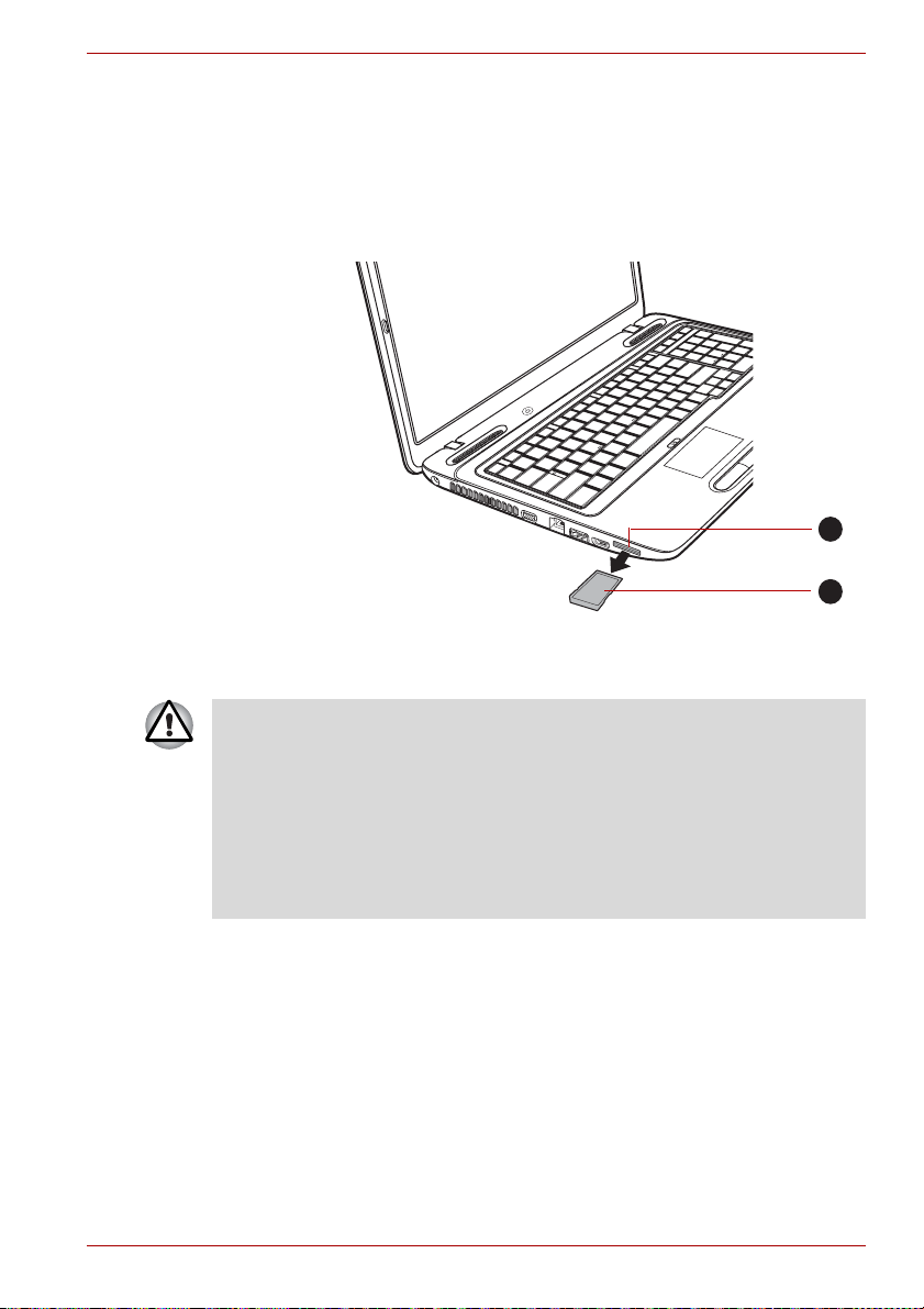
Hardware, Utilities and Options
Removing a memory media
The following instructions apply to all types of supported media devices. To
remove a memory media, follow the steps as detailed below:
1. Open the Safely Remove Hardware icon on the Windows Taskbar.
2. Point to memory media and click the left Touch Pad control button.
3. Grasp the media and remove it.
1. Bridge media slot 2. Memory media
Removing memory media
1
2
■ Make sure the Bridge Media slot indicator is out before you remove
the memory media or turn off the computer’s power. If you remove the
memory media or turn off the power while the computer is accessing
the memory media, you may lose data or damage the media.
■ Do not remove the memory media while the computer is in Sleep or
Hibernation Mode. The computer could become unstable or data in the
memory media could be lost.
■ Do not remove only the miniSD/microSD Card while leaving the
adaptor in the Bridge Media slot.
User’s Manual 3-17
Page 69

Hardware, Utilities and Options
Additional memory module
You can install additional memory into the computer in order to increase the
amount of system memory that is available. This section describes how to
install and remove optional memory modules.
■ You should place a mat beneath the computer in order to prevent the
computer's lid from becoming scratched or damaged when you are
installing/replacing the memory module. In this instance you should
avoid mats that are made of materials that hold or generate static
electricity.
■ When installing or removing a memory module, you must ensure that
you do not touch any other internal areas of the computer.
■ Insert the two memory modules into Slot A and Slot B respectively.
The computer will operate in dual channel mode.
You can access the inserted memory modules efficiently in dual
channel.
■ Use only memory modules approved by TOSHIBA.
■ Do not try to install or remove a memory module under the following
conditions.
a. The computer is turned on.
b. The computer was shut down in either Sleep or Hibernation Mode.
c. Wake-up on LAN is enabled.
■ Be careful not to let screws or other foreign matter fall into the
computer. It could cause malfunction or electric shock.
■ Additional memory module is a precision electronic component that
may be fatally damaged by static electricity. Since the human body can
carry static electricity, it is important that you discharge yourself before
touching or installing any additional memory modules. To discharge
your body’s static electricity, simply touch any metal close to you with
bare hands.
Point to note about memory module error
If you install a memory module that is not compatible with the computer, the
Power indicator will flashes (on for 0.5 seconds, off for 0.5 seconds) in the
following ways;
■ If there is an error in only Slot A: repeatedly flashes amber twice, then
white.
■ If there is an error in only Slot B: repeatedly flashes amber, then white
twice.
■ If there are errors in both Slot A and Slot B: repeatedly flashes amber
twice, then white twice.
In all instances you should shut down the computer and remove the
incompatible module(s).
Use a point size 0 Phillips screwdriver to remove and fasten the screws the use of an incorrect screwdriver can damage the screw heads.
User’s Manual 3-18
Page 70

Hardware, Utilities and Options
Installing a memory module
To install a memory module, follow the steps as detailed below:
1. Shut down the computer - make sure the Power indicator is off (refer to
the Turning off the power section in Chapter 1, Getting Started if
required).
2. Remove the AC adaptor and all cables and peripherals connected to
the computer.
3. Close the display panel.
4. Turn the computer upside down and remove the battery pack (refer to
Replacing the battery pack section in Chapter 6, Power and Power-Up
Modes, if required).
5. Loosen the one screw securing the memory module cover in place please note that this screw is attached to the cover in order to prevent it
from being lost.
Use a point size 0 Phillips screwdriver.
6. Slide your fingernail or a thin object under the cover and lift it off.
1
2
1. Memory module cover 2. Screw
Removing the memory module cover
7. Align the notch of the memory module with that of the memory slot and
gently insert the module into the slot at about a 45 degree angle before
holding it down until the latches on either side snap into place.
User’s Manual 3-19
Page 71

Hardware, Utilities and Options
1
2
3
1. Notch 3. Slot B
2. Slot A
Seating the memory module
■ Never allow metal objects, such as screws, staples and paper clips, to
enter the computer. Foreign metal objects can create a short circuit,
which can cause computer damage and fire, possibly resulting in
serious injury.
■ Do not touch the connectors on the memory module or on the
computer. Debris on the connectors may cause memory access
problems.
■ The slot A is reserved for the first memory module. Use the slot B for
expanded memory. If only one module is installed, use the slot A.
When inserting or removing memory modules, use the A and B
marked on the computer chassis to determine which slot is A and
which is B.
■ Align the grooves along the edges of the memory module with the
locking tabs on the connector and insert the module into the connector
firmly - if you find it difficult to install the memory module, gently prise
the locking tabs outwards using the tip of your finger.
Please also ensure that you hold the memory module along its left and
right hand edges - the edges with the grooves in.
8. Seat the memory module cover in place and secure it with one screw.
Take care to ensure that the memory module cover is firmly closed.
User’s Manual 3-20
Page 72

Hardware, Utilities and Options
1
2
1. Memory module cover 2. Screw
Seating the memory module cover
9. Install the battery pack - refer to Replacing the battery pack section in
Chapter 6, Power and Power-Up Modes, if required.
10. Turn your computer over.
11. Turn the computer on and make sure the added memory is recognized to confirmed it, Start Control Panel System and Security
System icon.
Removing a memory module
To remove the memory module, follow the steps as detailed below:
1. Shut down the computer - make sure the Power indicator is off (refer to
the Turning off the power section in Chapter 1, Getting Started if
required).
2. Remove the AC adaptor and all cables and peripherals connected to
the computer.
3. Close the display panel.
4. Turn the computer upside down and remove the battery pack (refer to
Replacing the battery pack section in Chapter 6, Power and Power-Up
Modes, if required).
5. Loosen the one screw securing the memory module cover in place please note that this screw is attached to the cover in order to prevent it
from being lost.
6. Slide your fingernail or a thin object under the cover and lift it off.
7. Push the latches away from the module in order to release it - a spring
will force one end of the module up at an angle.
8. Grasp the module by its edges and remove it from the computer.
User’s Manual 3-21
Page 73

Hardware, Utilities and Options
■ If you use the computer for a long time, the memory modules and the
circuits locating close to the memory modules will become hot. In this
case, let them cool to room temperature before you replace them. Or
you will get burnt if you touch any of them.
■ Do not touch the connectors on the memory module or on the
computer. Debris on the connectors may cause memory access
problems.
1
1. Latches
Removing the memory module
9. Seat the memory module cover in place and secure it with one screw.
Take care to ensure that the memory module cover is firmly closed.
10. Install the battery pack - refer to Replacing the battery pack section in
Chapter 6, Power and Power-Up Modes, if required.
11. Turn your computer over.
User’s Manual 3-22
Page 74

Hardware, Utilities and Options
External monitor
An external analog monitor can be connected to the external monitor port
on the computer. To connect a monitor, follow the steps as detailed below:
Connecting the monitor cable
1. Turn the computer's power off.
2. Connect the monitor cable to the external monitor port and tighten the
screws on the left and right hand side of the connector as required.
1
2
1. External monitor port 2. Monitor cable
Connecting the monitor cable to the external monitor port
3. Turn the external monitor's power on.
4. Turn the computer's power on.
When you turn on the power, the computer will automatically recognize the
monitor and determine whether it is a color or monochrome device. In the
event that you find that there are issues getting an image displayed on the
correct monitor, you should consider using the FN + F5 hot key to change
the display settings (if you then disconnect the external monitor before you
turn the computer's power off, be sure to press FN + F5 hot key again to
switch to the internal display).
Please refer to Chapter 5, The Keyboard, for further details on using hot
keys to change the display setting.
Do not disconnect the external monitor while in Sleep or Hibernation
Mode. Turn off the computer before disconnecting the external monitor.
When displaying desktop at external analog monitor, desktop is sometimes
displayed on the center of the monitor with black bars around desktop (with
small size).
At that time, please read the manual of the monitor and set the display
mode which is supporting at the monitor. Then it will be displayed with
suitable size with correct aspect ratio.
User’s Manual 3-23
Page 75
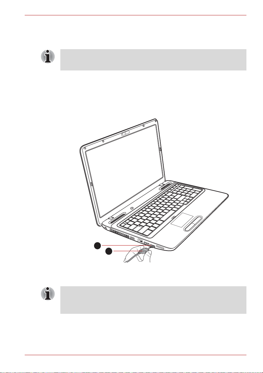
Hardware, Utilities and Options
HDMI
A HDMI monitor can be connected to the HDMI out port on the computer.
To connect monitor, follow the steps as detailed below:
As the port operation of all HDMI (High-Definition Multimedia Interface)
monitors have not been confirmed, some HDMI monitors may not function
properly.
Connecting the HDMI out port
1. Plug one end of the HDMI cable into the HDMI out port of the HDMI
device.
2. Plug the other end of the HDMI cable into the HDMI out port on your
computer.
1
2
1. HDMI out port 2. HDMI cable
Connecting the HDMI out port
When connecting or disconnecting an HDMI device to or from the
computer, only do so when the computer is turned on or when the
computer is completely turned off. Do not do so when the computer is in
Sleep Mode or Hibernation Mode.
User’s Manual 3-24
Page 76

Hardware, Utilities and Options
■ When you connect a television or external monitor to the HDMI port
and the display output device is set to HDMI.
When you unplug the HDMI cable and re-plug it in please wait at least
5 seconds before you replug the HDMI cable again.
■ When you connect a television or external monitor to the HDMI port
and you connect the television, external monitor or external sound
device to another port.
When you change the display output or Unplug/re-plug the HDMI
cable.
The sound output device and the display output device maybe
changed automatically by the system.
Select HD Format
To select the display mode, follow the steps as detailed below:
1. Click Start and click Control Panel.
2. Click Appearance and Personalization.
3. Click Display.
4. Click Change display settings.
5. Click Advanced settings.
6. Click List All Modes.
7. Select the one of the below selection at "List All Modes".
Display mode at "List All Modes" HD Format
1920 by 1080, True Color (32bit), 60 Herts 1080p
1920 by 1080, True Color (32bit), 30 Herts
(Interlaced)
1280 by 720, True Color (32bit), 60 Herts 720p
720 by 576, True Color (32bit), 50 Herts 576p
720 by 480, True Color (32bit), 60 Herts 480p
1080i
The above display mode is a typical HDMI display mode. The selectable
display modes will vary for different HDMI monitors.
User’s Manual 3-25
Page 77

Hardware, Utilities and Options
USB FDD Kit
The USB floppy diskette drive accommodates either a 1.44MB or 720KB
floppy diskette and connects to one of the computer's USB ports.
1
2
3
1. USB connector 3. Floppy diskette slot
2. Disk-In-Use Indicator 4. Eject button
The USB floppy diskette drive
Connecting the USB floppy diskette drive
To connect the drive, plug the floppy diskette drive’s USB connector into a
computer’s USB port.
Make sure the connector is properly aligned with the socket. Do not try to
force the connection, doing so can damage the connecting pins.
4
1
2
1. USB port 2. USB connector
Connecting the USB floppy diskette drive
If you connect the USB floppy diskette drive after the computer has
already been turned on, it will take about ten seconds for it to be
recognized by the computer. Do not attempt to disconnect and reconnect
the drive before this period has elapsed.
User’s Manual 3-26
Page 78

Hardware, Utilities and Options
Disconnecting the USB floppy diskette drive
When you have finished using the USB floppy diskette drive, you can follow
the procedures below in order to disconnect it:
1. Wait for the Disk-In-Use Indicator light to go out to make sure all floppy
diskette activity has stopped.
If you disconnect the USB floppy diskette drive or turn off the power while
the computer is accessing the drive you may lose data or damage the
floppy diskette or the drive.
2. Click the Safely Remove Hardware icon on the Windows Taskbar.
3. Click the USB floppy diskette drive device that you want to remove.
4. Carefully pull the floppy diskette drive's USB connector out from within
the computer's USB port.
eSATA (External Serial ATA)
An device corresponding to eSATA function can be connected to the
eSATA/USB combo port on the computer.
Connecting the eSATA device
To connect an eSATA device, follow the steps as detailed below:
1. Connect an eSATA cable to the eSATA/USB combo port.
Make sure the connector is properly aligned with the socket.
Do not try to force the connection, doing so can damage the connecting
pins.
1
2
1. eSATA/USB combo port 2. eSATA cable
Connecting an eSATA cable to the eSATA/USB combo port
User’s Manual 3-27
Page 79

Hardware, Utilities and Options
■ A connected eSATA device may not be recognized if it is connected to
the computer's eSATA/USB combo port while the computer is in Sleep
Mode or Hibernation Mode. If this occurs, disconnect the eSATA
device and then reconnect the device while the computer is turned on.
■ If you connect an eSATA device after the computer has already been
turned on, it will take about ten seconds for it to be recognized by the
computer.
Do not attempt to disconnect and reconnect the drive before this
period has elapsed.
Disconnecting an eSATA device
When you have finished using an eSATA device, you can follow the
procedures below in order to disconnect it:
1. Wait for the indicator light of an eSATA device to go out to make sure all
activity has stopped.
If you disconnect an eSATA device or turn off the power while the
computer is accessing the drive you may lose data or damage an eSATA
device or the drive.
2. Click the Safely Remove Hardware icon on the Windows Taskbar.
3. Click an eSATA device that you want to remove.
4. Carefully pull an eSATA device's eSATA/USB combo connector out
from within the computer's eSATA/USB combo port.
Security lock
A security locks enable you to anchor your computer a desk or other heavy
object in order to help prevent unauthorized removal or theft. The computer
has a security lock slot on its back side into which you can attach one end
of the security cable, while the other end attaches to a desk or similar
object. The methods used for attaching security cables differ from product
to product. Please refer to the instructions for the product you are using for
more information.
Connecting the security lock
In order to connect a security cable to the computer, follow the steps as
detailed below:
1. Turn the computer so its back side faces you.
2. Align the security cable with the lock slot and secure it in place.
User’s Manual 3-28
Page 80

1. Security lock slot
Optional accessories
You are able to add a number of options and accessories in order to make
your computer even more powerful and convenient to use. For reference,
the following list details some of the items that are available from your
reseller or TOSHIBA dealer:
Hardware, Utilities and Options
1
Security lock
DDR3-1066 Memory
Kit
A 1 GB, 2 GB or 4 GB memory module (DDR3-
1066) can easily be installed in the computer.
Universal AC Adaptor If you frequently use your computer at more than
one site, it may be convenient to purchase an
additional AC adaptor to be kept at each site in
order to remove the need to always carry the
adaptor with you.
Battery Pack An additional battery pack can be purchased for
use as either a spare or replacement. Please
refer to Chapter 6, Power and Power-Up Modes
for further information.
USB FDD Kit The USB floppy diskette drive accommodates
either a 1.44MB or 720KB floppy diskette
through connection to one of the computer's USB
ports. In use, please be aware that, while you
cannot format 720KB floppy diskettes under
Windows 7, you are able to read and write to
diskettes that have already been formatted.
Security lock A slot is available to attach a security cable to the
computer to deter theft.
User’s Manual 3-29
Page 81

Operating Basics
This chapter describes the basic operations of your computer, highlights
the precautions that should be taken when using it.
Using the Touch Pad
To use the Touch Pad, simply touch and move your fingertip across it in the
direction you want the on-screen pointer to go.
1
Operating Basics
Chapter 4
2
3
1. Touch Pad ON/OFF button* 3. Touch Pad control buttons
2. Touch Pad
Touch Pad and Touch Pad control buttons
* Provided with some models
The two buttons below the Touch Pad are used like the buttons on a
standard mouse - press the left button to select a menu item or to
manipulate text or graphics designated by the pointer, and press the right
button to display a menu or other function depending on the software you
are using. Press the Touch Pad ON/OFF button to enable or disable the
Touch Pad function.
User’s Manual 4-1
Page 82

You can also tap the Touch Pad to perform functions similar to those of the
left button on a standard mouse.
Click: Tap once
Double-click: Tap twice
Drag and drop: Tap to select the item(s) you want to move, leave your
finger on the Touch Pad after the second tap and then move the item(s) to
their new destination.
Touch Pad Gesture
There are four convenient gestures that make users operate the system
easier and faster. In the Mouse Properties you can enable/disable these
functions.
ChiralMotion
You can scroll vertically and horizontally. To enable these features, select
the Enable vertical scrolling and Enable horizontal scrolling check
boxes.
Click on the window or item you wish to scroll and slide your finger upwards
or downwards along the right edge of the TouchPad to scroll vertically. Slide
your finger to the left or right along the lower edge of the TouchPad to scroll
horizontally.
If scrolling does not respond, ensure that the appropriate check box is
selected and that the window or item on which you have clicked is
scrollable. If you still have problems, check your Scrolling Region settings.
Operating Basics
Pinch Zoom (Pinch)
The Pinch Zoom gesture delivers zooming functionality in many
applications. You can use the Pinch Zoom gesture to perform the same
functions that a scroll wheel performs on standard Windows applications
that support CTRL-SCROLL WHEEL zoom functionality. To enable this
feature, select the Enable Pinch Zoom check box. To use a Pinch Zoom
gesture:
1. Place two fingers down on the TouchPad surface.
2. Slide the fingers further apart to zoom in or slide the fingers closer
together to zoom out. For the best zooming experience, use the tips of
your fingers.
Rotating (ChiralRotate)
The Rotating features provide convenient gestures for rotating photos and
other objects.
User’s Manual 4-2
Page 83

Momentum
The Momentum feature delivers smooth, fast, trackball-like mouse
movement. One quick flick of the finger on the Touch Pad surface can
move the cursor across the entire computer screen. Momentum reduces
the repetitive motion and fatigue associated with moving the cursor long
distances, while providing a smooth and natural feel similar to using a
trackball. Momentum is ideal for Real Time Strategy (RTS) games, First
Person Shooter (FPS) games, and Role Playing Games (RPG). The two
buttons below the Touch Pad are used like the buttons on a standard
mouse - press the left button to select a menu item or to manipulate text or
graphics designated by the pointer, and press the right button to display a
menu or other function depending on the software you are using.
Web Camera
Web Camera is a device that allows you to record video or take
photographs with your computer. You can use it for video chatting or video
conferences using a communication tool such as Windows Live
Messenger. TOSHIBA Web Camera Application will help you to add
various video effects to your video or photograph.
Enables the transmission of video and use of video chat via the internet
using specialized applications.
The effective pixel count for this web camera is 0.3 million (maximum
photograph size: 640x480 pixels) or 1.3 million (maximum photograph
size: 1280 × 1024 pixels).
Some models are equipped with a Web Camera.
Please refer to the Web Camera Application Online Help for details.
Operating Basics
1
23
1. Web Camera 3. Microphone
2. Web Camera LED
Web Camera
User’s Manual 4-3
Page 84
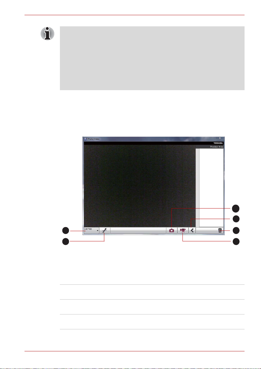
■ Do not point the web camera directly at the sun.
■ Do not touch or press strongly on the web camera lens. Doing so may
reduce image quality. Use an eyeglass cleaner (cleaner cloth) or other
soft cloth to clean the lens if it becomes dirty.
■ Setting the [Size] to more than "800x600" will cause a larger amount of
data to be written to the hard disk drive and may interfere with smooth
recording.
■ When recording in dimly lit environments, select "Night Mode" which
allows for brighter images with less noise.
Using TOSHIBA Web Camera Application
TOSHIBA Web Camera Application is pre-configured to start when you turn
on Windows
TOSHIBA Utilities Web Camera Application.
®
7; if you need to restart it go to Start All Programs
Operating Basics
1
2
5
6
1. Capture Still Images 4. Video Recording
2. Open/Close Preview Area 5. Camera Resolution
3. Delete Recorded File 6. Capture Settings
Using the Software
3
4
Capture Still Image Click to capture a still image, and see a preview
of the captured image in preview area.
Open/Close Preview
Area
Click to open Preview Area. One more to close
Preview Area.
Delete Recorded File Choose a thumbnail of recorded file and click this
button to delete this file from hard disk.
User’s Manual 4-4
Page 85

Video Recording Click to start recording. One more to stop
recording and see preview of the video in
preview area.
Camera Resolution Choose resolution for Preview, Capture and
Record.
Capture Settings Open Capture Settings dialog box.
Chooses from the Basic tab to select photo and
video saving location, select Capture Format and
Video Quality.
Using the TOSHIBA Face Recognition
TOSHIBA Face Recognition uses a face verification library to verify the
face data of users when they log in to Windows. The user can thus avoid
having to enter a password or the like, which makes the login process
easier.
■ TOSHIBA Face Recognition does not guarantee the correct
identification of a user. Changes to the likeness of a registrant, such as
hair style changes, wearing a cap, or wearing glasses may effect the
recognition rates when such changes occur after the registrant had
registered.
■ TOSHIBA Face Recognition may incorrectly recognize faces that are
similar to a registrant.
■ For high security purposes, TOSHIBA Face Recognition is not a
suitable substitute for Windows passwords. When security is a high
priority, use your established Windows passwords to log in.
■ Bright background light and/or shadows may prevent a registrant from
being recognized correctly. In that case, log in using your Windows
password. If recognition of a registrant fails repeatedly, refer to your
computer documentation to learn ways to improve recognition
performance.
■ TOSHIBA Face Recognition records face data in a log when face
recognition fails. When transferring ownership or disposing of your
computer, please uninstall the application or delete all the logs created
by the application. For details on how to do this, see help file.
■ TOSHIBA Face Recognition can be used only in Windows 7.
Operating Basics
User’s Manual 4-5
Page 86

Disclaimer
Toshiba does not guarantee that the face recognition utility technology will
be completely secure or error-free. Toshiba does not guarantee that the
face recognition utility will accurately screen out unauthorized users at all
times. Toshiba is not liable for any failure or damage that might arise out of
the use of the face recognition software or utility.
TOSHIBA, ITS AFFILIATES AND SUPPLIERS SHALL HAVE NO
RESPONSIBILITY FOR DAMAGE TO OR LOSS OF ANY BUSINESS,
PROFITS, PROGRAMS, DATA, NETWORK SYSTEMS OR REMOVABLE
STORAGE MEDIA ARISING OUT OF OR RESULTING FROM THE USE
OF THE PRODUCT, EVEN IF ADVISED OF THE POSSIBILITY
THEREOF.
How to register the Face Recognition Data
Take a picture for facial verification purposes, and register the data needed
when you log in. To register the data needed when you log in, follow the
steps as described below:
1. To launch this utility, click Start All Programs TOSHIBA
Utilities Face Recognition.
■ The Registration screen is displayed for a logged-in user whose
face has not been registered.
■ The Management screen is displayed for a logged-in user whose
face has already been registered.
2. Click Run as administrator in lower left of the Management screen,
and then click the Register button. The Registration screen is
displayed.
■ If you wish to practice, click on the Next button in the Registration
screen.
■ If you do not wish to practice, click on the Skip button in the
Registration screen.
3. Click the Next button to start the guide. Please follow the guide to
practice.
■ Click the Back button to practice the guide once more.
4. Click the Next button to start image-capturing process.
Adjust the position of your face so that it fits within the face-shaped
frame.
5. Once your face has been positioned properly, the recording will
commence.
Start moving your neck very slightly to the left and right, and then move
your neck down and up.
Operating Basics
User’s Manual 4-6
Page 87

6. Registration will end after you have repeatedly moved your neck left,
right, down and up.
When the register succeeds, below message will be displayed on the
screen:
"Registration successful. Now we’ll do the
verification test. Click the Next button."
Click the Next button to perform the verification test.
7. Perform the verification test. Face the screen as you do when you
register.
■ If verification fails, click the Back button and re-register. Please refer
to step 6 from step 4.
8. If verification is successful, click the Next button and register an
account.
9. Register the account. Fill in all the fields.
10. The Management screen is displayed.
The registered account name will be displayed. Clicking on it will cause
the captured image of your face to be displayed on the left.
How to Delete the Face Recognition Data
Delete image data, account information, and personal record data created
during registration. To delete the Face Recognition Data, follow the steps
as described below:
1. To launch this utility, click Start All Programs TOSHIBA
Utilities Face Recognition.
The Management screen is displayed.
2. Select a user which is displayed in the Management screen.
3. Click the Delete button. "You are about to delete the user
data. Would you like to continue?" will be displayed on the
screen.
■ If you do not want the data to be deleted, click the No button and
you will then be returned to the Management screen.
■ Clicking on the Yes button will remove the selected user from the
Management screen.
Operating Basics
How to launch the help file
For further information on this utility, please refer to help file.
1. To launch the help file, click Start All Programs TOSHIBA
Utilities Face Recognition Help.
User’s Manual 4-7
Page 88

Windows Logon via TOSHIBA Face Recognition
This section explains how to login to Windows with TOSHIBA Face
Recognition. Two authentication modes are provided.
■ 1:N Mode Login screen: If the face authentication tile is selected by
default, you can log in without using the keyboard or mouse.
■ 1:1 Mode Login screen: This mode is essentially the same as AUTO
mode, but the Select Account screen will appear before the Display
Captured Image screen, and you will need to select the user account
to be authenticated in order to start the authentication process.
1:N Mode Login screen
1. Turn on the computer.
2. The Select Tiles screen will be displayed.
3. Select Start face recognition ().
4. "Please face the camera" will be displayed.
5. Verification will be performed. If the authentication is successful, the
image data taken in step 4 will be faded in and placed over one another.
■ If an error occurs during authentication, you will be returned to the
Select Tiles screen.
6. The Windows Welcome screen will be displayed, and will be logged in
automatically to Windows.
Operating Basics
1:1 Mode Login screen
1. Turn on the computer.
2. The Select Tiles screen will be displayed.
3. Select Start face recognition ().
4. The Select Account screen will be displayed.
5. Select the account, and click the arrow button.
6. "Please face the camera" will be displayed.
7. Verification will be performed. If the authentication is successful, the
image data taken in step 6 will be faded in and placed over one another.
■ If an error occurs during authentication, you will be returned to the
Select Tiles screen.
8. The Windows Welcome screen will be displayed, and will be logged in
automatically to Windows.
■ If authentication was successful, but an authentication error
subsequently occurred during the login to Windows, you will be
asked to provide your account information.
User’s Manual 4-8
Page 89

Using optical disc drives
The full-size drive provides high-performance execution of CD/DVD/BD
based programs. You can run either 12 cm (4.72") or 8 cm (3.15")
CD/DVD/BDs without an adaptor. A Serial ATA interface controller is used
for CD/DVD/BD operation. When the computer is accessing a CD/DVD/BD,
an indicator on the drive glows.
Use the DVD playback application to view DVD-Video discs.
If you have a DVD SuperMulti drive, BD Writer drive or BD Combo drive,
refer also to the Writing CD/DVD/BDs on DVD Super Multi drives, BD
Writer drives or BD Combo drives section for precautions on writing to
CDs/DVDs/BDs.
Loading discs
To load CDs/DVDs/BDs, follow the steps as detailed below:
1. When the computer’s power is on, press the eject button to open the
disc tray slightly.
2. Grasp the disc tray gently and pull until it is fully opened.
Operating Basics
2
1
1. Disc tray 2. Eject button
Pressing the eject button and pulling the disc tray open
3. Lay the CD/DVD/BD, label side up, in the disc tray.
User’s Manual 4-9
Page 90

Operating Basics
1. Laser lens
Inserting a CD/DVD/BD
When the disc tray is fully opened, the edge of the computer will extend
slightly over the CD/DVD/BD tray. Therefore, you will need to turn the
CD/DVD/BD at an angle when you place it in the disc tray. After seating
the CD/DVD/BD, however, make sure it lies flat.
1
■ Do not touch the laser lens or any portion of its surrounding casing as
this could cause misalignment.
■ Prevent foreign objects from entering the drive. Check the surface of
the disc tray, especially the area behind the front edge of the disc tray,
to make sure there are no such objects before closing the drive.
4. Press gently at the center of the CD/DVD/BD until you feel it click into
place. The CD/DVD/BD should lie below the top of the spindle, flush
with the spindle base.
5. Push the center of the disc tray to close it. Press gently until it locks into
place.
If the CD/DVD/BD is not seated properly when the disc tray is closed, the
CD/DVD/BD might be damaged. Also, the disc tray might not open fully
when you press the eject button.
User’s Manual 4-10
Page 91

Closing the CD/DVD/BD disc tray
Removing discs
To remove the CD/DVD/BD, follow the steps as detailed below:
Do not press the eject button while the computer is accessing the media
drive. Wait for the optical disc drive indicator to go out before you open the
disc tray. Also, if the CD/DVD/BD is spinning when you open the disc tray,
wait for it to stop before you remove it.
1. To pop the disc tray partially open, press the eject button. Gently pull
the disc tray out until it is fully opened.
When the disc tray pops open slightly, wait a moment to make sure the
CD/DVD/BD has stopped spinning before pulling the disc tray fully open.
2. The CD/DVD/BD extends slightly over the sides of the disc tray so you
can grasp it. Gently lift out the CD/DVD/BD.
Operating Basics
Removing a CD/DVD/BD
3. Push the center of the disc tray to close it. Press gently until it locks into
place.
User’s Manual 4-11
Page 92
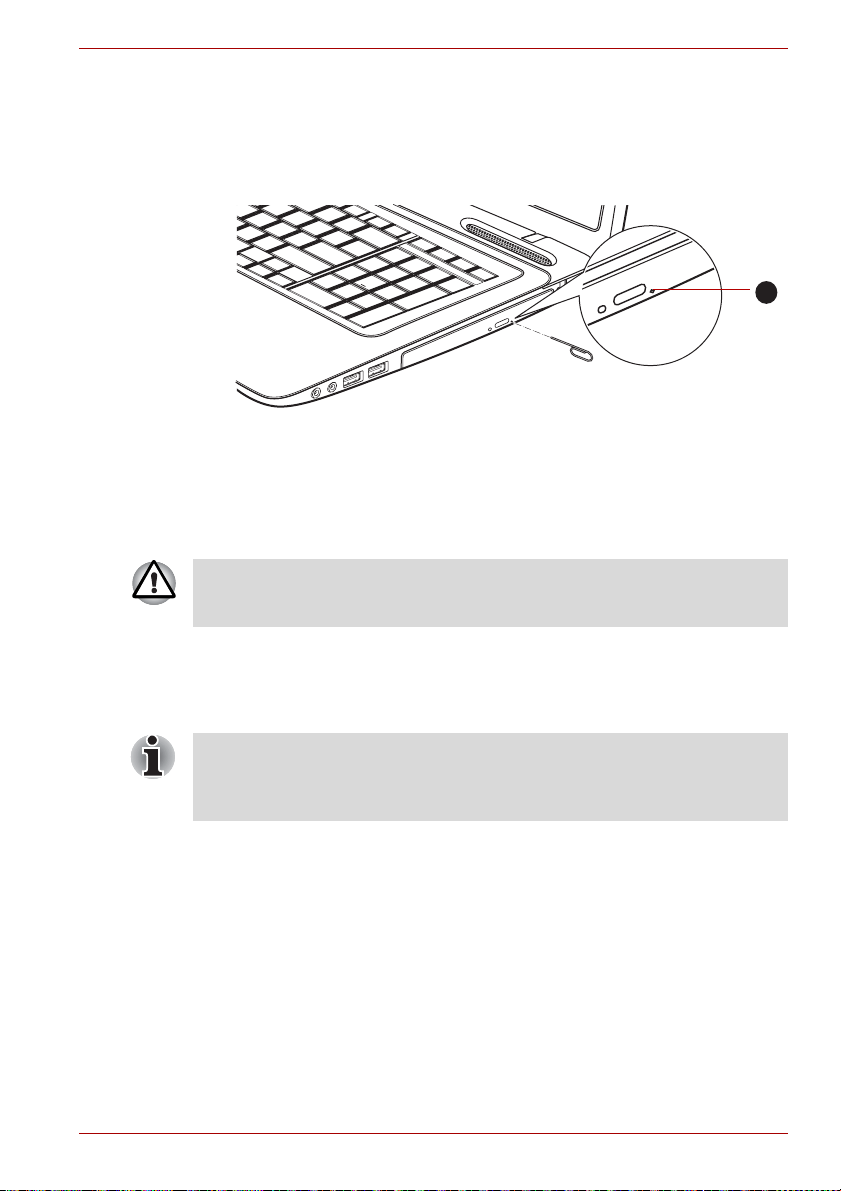
Operating Basics
How to remove CD/DVD/BD when the disc tray will not open
Pressing the eject button will not open the disc tray when the computer
power is off. If the power is off, you can open the disc tray by inserting a
slender object (about 15 mm) such as a straightened paper clip into the
eject hole near the eject button.
1. Eject hole
Manual release with the eject hole
Turn off the power before you use the eject hole. If the CD/DVD/BD is
spinning when you open the disc tray, the CD/DVD/BD could fly off the
spindle and cause injury.
1
Writing CD/DVD/BDs on DVD Super Multi drives, BD Writer drives or BD Combo drives
The optical drive installed on this computer cannot write multiple sessions
on DVD-R Dual Layer disc sessions. Once a disc has been written to
once, it will be finalized. Once finalized, no further writing to the disc will be
possible regardless of what portion of the total disc capacity was used.
You can use the DVD SuperMulti drive or BD Writer drives or BD Combo
drives to write data to either CD-R, CD-RW, DVD-R, DVD-R (Dual Layer),
DVD-RW, DVD+R, DVD+R (Double Layer), DVD+RW, DVD-RAM, DVD-R
(Dual Layer) or BD-R/BD-RE discs.
TOSHIBA Disc Creator and Corel DVD MovieFactory are provided as
writing software with this computer.
Corel DVD MovieFactory can be used to write files in video format.
TOSHIBA Disc Creator can be used to write data.
User’s Manual 4-12
Page 93

■ Please refer to the section Writable discs, Chapter 2 for details about
the types of writable CD, DVD and BD discs that can be supported by
this computer.
■ Do not turn off the power to the optical disc drive while the computer is
accessing it as this may cause you to lose data.
■ CD-R/RW media cannot be accessed using the Create CD/DVD/BD
option in Media Center.
■ To write data to CD-R/-RW media, use the TOSHIBA Disc Creator
feature that is installed on your computer.
When writing information to media using an optical drive, you should
always ensure that you connect the AC adaptor to a live power socket. It is
possible that, if data is written while powered by the battery pack, the write
process may sometimes fail due to low battery power - in these instances
data loss may occur.
Important message
Before you write or rewrite to any of the media supported by the DVD
Super Multi drive or BD drive, please read and follow all of the setup and
operating instructions in this section. If you fail to do so, you may find that
the DVD Super Multi drive or BD drive may not function properly, and you
may fail to write or rewrite information successfully. This may cause you to
either lose data or incur other damage to the drive or media.
Operating Basics
Disclaimer
TOSHIBA does not bear responsibility for the following:
■ Damage to any CD-R, CD-RW, DVD-R, DVD-R (Dual Layer), DVD-RW,
DVD+R, DVD+R (Double Layer), DVD+RW, DVD-RAM, BD-R, BDR(DL), BD-RE and BD-RE(DL) disc that may be caused by writing or
rewriting with this product.
■ Any change or loss of the recorded contents of CD-R, CD-RW, DVD-R,
DVD-R (Dual Layer), DVD-RW, DVD+R, DVD+R (Double Layer),
DVD+RW, DVD-RAM, BD-R, BD-R(DL), BD-RE and BD-RE(DL) media
that may be caused by writing orrewriting with this product, or for any
business profit loss or business interruption that may be caused by the
change or loss of the recorded contents.
■ Damage that may be caused by using third party equipment or
software.
Given the technological limitations of current optical disc writing drives, you
may experience unexpected writing or rewriting errors due to disc quality or
problems with hardware devices. In view of this, it is good practice to make
two or more copies of important data, in case of any undesired change or
loss of the recorded contents.
User’s Manual 4-13
Page 94

Before writing or rewriting
■ Based on TOSHIBA's limited compatibility testing, we suggest the
following manufacturers of CD-R, CD-RW, DVD-R, DVD-R (Dual
Layer), DVD-RW, DVD+R, DVD+R (Double Layer), DVD+RW, DVDRAM, BD-R, BD-R(DL), BD-RE and BD-RE(DL) media, however, it
must be noted that disc quality can affect write or rewrite success rates.
Please also be aware that in no event does TOSHIBA guarantee the
operation, quality or performance of any disc.
CD-R:
TAIYO YUDEN CO., Ltd.
MITSUBISHI KAGAKU MEDIA CO., LTD.
Hitachi Maxell,Ltd.
CD-RW: (Multi-Speed and High-Speed)
MITSUBISHI KAGAKU MEDIA CO., LTD.
CD-RW: (Ultra-Speed)
MITSUBISHI KAGAKU MEDIA CO., LTD.
DVD-R:
DVD Specifications for Recordable Disc for General Version 2.0
TAIYO YUDEN Co.,Ltd. (for 8x and 16x speed media)
MITSUBISHI KAGAKU MEDIA CO., LTD. (for 4x, 8x and 16x speed
media)
Hitachi Maxell,Ltd. (for 8x and 16x speed media)
DVD-R (Dual Layer):
MITSUBISHI KAGAKU MEDIA CO., LTD. (for 4x and 8x speed media)
DVD-R for Labelflash:
FUJIFILM CORPORATION (for 16x speed media)
DVD+R:
MITSUBISHI KAGAKU MEDIA CO., LTD. (for 8x and 16x speed
media)
TAIYO YUDEN CO., Ltd. (for 8x and 16x speed media)
DVD+R (Double Layer):
MITSUBISHI KAGAKU MEDIA CO., LTD. (for 2.4x and 8x speed
media)
DVD+R for Labelflash:
FUJIFILM CORPORATION (for 16x speed media)
DVD-RW:
DVD Specifications for Recordable Disc for Version 1.1 or version 1.2
Victor Company of Japan, Ltd. (JVC) (for 2x, 4x and 6x speed media)
MITSUBISHI KAGAKU MEDIA CO., LTD. (for 2x, 4x and 6x speed
media)
Operating Basics
User’s Manual 4-14
Page 95

Operating Basics
DVD+RW:
MITSUBISHI KAGAKU MEDIA CO., LTD. (for 2.4x, 4x and 8x speed
media)
DVD-RAM: (DVD Super Multi drive only)
DVD Specifications for DVD-RAM Disc for Version 2.0, Version 2.1
or Version 2.2
Panasonic Corporation (for 3x and 5x speed media)
Hitachi Maxell,Ltd. (for 3x and 5x speed media)
BD-Combo drive
CD-R:
TAIYO YUDEN CO., Ltd.
MITSUBISHI KAGAKU MEDIA CO., LTD.
Hitachi Maxell,Ltd.
CD-RW: (Multi-Speed and High-Speed)
MITSUBISHI KAGAKU MEDIA CO., LTD.
CD-RW: (Ultra-Speed)
MITSUBISHI KAGAKU MEDIA CO., LTD.
DVD-R: (DVD Specifications for Recordable Disc for General Version
2.0)
TAIYO YUDEN Co.,Ltd. (for 8x and 16x speed media)
MITSUBISHI KAGAKU MEDIA CO., LTD. (for 4x, 8x and 16x speed
media)
Hitachi Maxell,Ltd. (for 8x and 16x speed media)
DVD-R for Labelflash:
FUJIFILM CORPORATION (for 16x speed media)
DVD+R:
MITSUBISHI KAGAKU MEDIA CO., LTD. (for 8x and 16x speed
media)
DVD+R for Labelflash:
FUJIFILM CORPORATION (for 16x speed media)
DVD-RW:
DVD Specifications for Recordable Disc for Version 1.1 or version 1.2
Victor Company of Japan, Ltd. (JVC) (for 2x, 4x and 6x speed media)
MITSUBISHI KAGAKU MEDIA CO., LTD. (for 2x, 4x and 6x speed
media)
DVD-RAM: (DVD Specifications for DVD-RAM Disc for Version 2.0,
Version 2.1 or Version 2.2)
Panasonic CO., LTD. (for 3x and 5x speed media)
Hitachi Maxell,Ltd. (for 3x and 5x speed media)
User’s Manual 4-15
Page 96

Operating Basics
BD Writer drive
CD-R:
TAIYO YUDEN CO., Ltd.
MITSUBISHI KAGAKU MEDIA CO., LTD.
Hitachi Maxell,Ltd.
CD-RW: (Multi-Speed and High-Speed)
MITSUBISHI KAGAKU MEDIA CO., LTD.
CD-RW: (Ultra-Speed)
MITSUBISHI KAGAKU MEDIA CO., LTD.
DVD-R: (DVD Specifications for Recordable Disc for General Version
2.0)
TAIYO YUDEN Co.,Ltd. (for 8x and 16x speed media)
MITSUBISHI KAGAKU MEDIA CO., LTD. (for 4x, 8x and 16x speed
media)
DVD-R for Labelflash:
FUJIFILM CORPORATION (for 16x speed media)
DVD+R:
MITSUBISHI KAGAKU MEDIA CO., LTD. (for 8x and 16x speed
media)
DVD+R for Labelflash:
FUJIFILM CORPORATION (for 16x speed media)
DVD-RW:
DVD Specifications for Recordable Disc for Version 1.1 or version 1.2
Victor Company of Japan, Ltd. (JVC) (for 2x, 4x and 6x speed media)
MITSUBISHI KAGAKU MEDIA CO., LTD. (for 2x, 4x and 6x speed
media)
DVD-RAM: (DVD Specifications for DVD-RAM Disc for Version 2.0,
Version 2.1 or Version 2.2)
Panasonic CO., LTD. (for 3x and 5x speed media)
Hitachi Maxell,Ltd. (for 3x and 5x speed media)
BD-R:
Panasonic CO., LTD.
BD-R(DL):
Panasonic CO., LTD.
BD-RE:
Panasonic CO., LTD.
BD-RE(DL):
Panasonic CO., LTD.
User’s Manual 4-16
Page 97

Operating Basics
■ DVD Super Multi drive cannot use discs that allow writing faster than
16x speed (DVD-R and DVD+R media), 8x speed (DVD-R (Dual
Layer), DVD+RW and DVD+R (Double Layer) media), 6x speed
(DVD-RW media), 5x speed (DVD-RAM media).
■ Some types and formats of DVD-R (Dual Layer) and DVD+R (Double
Layer) discs may be unreadable.
■ 2.6GB and 5.2GB DVD-RAM media cannot be read from or written to.
■ DISC created in DVD-R (Dual Layer) format4 (Layer Jump Recording)
cannot be read.
■ If the disc is poor in quality, or is dirty or damaged, writing or rewriting
errors may be noted - ensure that you check all discs for dirt or damage
before you use them.
■ The actual number of rewrites to CD-RW, DVD-RW, DVD+RW or DVD-
RAM media will be affected by the quality of the disc itself and the way
in which it is used.
■ There are two types of DVD-R media available, authoring discs and
general use discs. Do not attempt to use authoring discs as only
general use discs can be written to by a computer drive.
■ You can use both DVD-RAM discs that can be removed from a cartridge
and DVD-RAM discs designed without a cartridge.
■ You may find that other computer DVD-ROM drives or other DVD
players may not be able to read DVD-R, DVD-R (Dual Layer), DVD-RW,
DVD+R, DVD+R (Double Layer) or DVD+RW discs.
■ Data written to a CD-R, DVD-R, DVD-R (Dual Layer), DVD+R or
DVD+R (Double Layer) discs cannot be deleted either in whole or in
part.
■ Data deleted/erased from a CD-RW, DVD-RW, DVD+RW or DVD-RAM
disc cannot be recovered. You must check the content of the disc
carefully before you delete it, taking care that, if multiple drives that can
write data to discs are connected, you do not delete data from the
wrong one.
■ In writing to DVD-R, DVD-R (Dual Layer), DVD-RW, DVD+R, DVD+R
(Double Layer), DVD+RW or DVD-RAM media, some space is required
for file management, so you may not be able to write to the full capacity
of the disc.
■ Since the disc is based on the DVD standard, it might be filled with
dummy data if the written data is less than about 1GB. Therefore, in
these circumstance, even if you write only a small amount of data, it
might take additional time to fill in the dummy data.
■ When multiple drives that can write data to discs are connected, be
sure that you do not write to or delete data from the wrong drive.
■ Be sure to connect the AC adaptor to the computer before you write or
rewrite any information.
■ Before you enter either Sleep Mode or Hibernation Mode, take care to
ensure that any DVD-RAM writing has been completed. In this instance,
writing is finished if you can eject the DVD-RAM media.
User’s Manual 4-17
Page 98

■ Be sure to close all other software programs except for the writing
software itself.
■ Do not run software such as a screen saver which can put a heavy load
on the processor.
■ Operate the computer at its full power settings - do not use any power-
saving features.
■ Do not write information while virus checking software is running,
instead wait for it to finish, then disable the virus protection applications,
including any software that checks files automatically in the
background.
■ Do not use any hard disk utilities, including those that are intended to
enhance hard disk drive access speeds, as they may cause unstable
operation and damage data.
■ CD-RW (Ultra Speed +) media should not be used as data may be lost
or damaged.
■ You should always write from the computer's hard disk drive onto the
CD/DVD - do not try to write from shared devices such as a server or
any other network device.
■ Writing with software other than TOSHIBA Disc Creator has not been
confirmed, therefore operation with other software applications cannot
be guaranteed.
When writing or rewriting
Please observe the following points while you write or rewrite data to CD-R,
CD-RW, DVD-R, DVD-R (Dual Layer), DVD-RW, DVD+R, DVD+R (Double
Layer), DVD+RW or DVD-RAM media:
■ Always copy data from the hard disk drive to the optical media - do not
use the cut-and-paste function as the original data will be lost if there is
a write error.
■ Do not perform any of the following actions:
■ Change users in the Windows
■ Operate the computer for any other function, including such tasks as
using a mouse or Touch Pad, or closing/opening the display panel.
■ Start a communication application such as a modem.
■ Apply impact or vibration to the computer.
■ Install, remove or connect external devices, including such items as a
SD/SDHC/SDXC memory card, miniSD/microSD Card, Memory
Stick/Memory Stick PRO, MultiMediaCard, USB device, external
monitor, or an optical digital device or BD drive.
■ Use the audio/video control button to reproduce music or voice.
■ Open the optical disc drive or BD drive.
■ Do not use shut down, log off, Sleep Mode or Hibernation Mode
functions while writing or rewriting.
®
7 operating system.
Operating Basics
User’s Manual 4-18
Page 99

■ Make sure that the write/rewrite operation is completed before going
into either Sleep Mode or Hibernation Mode (writing is completed if you
can remove an optical media on the DVD Super Multi drive or BD drive).
■ If the media is of poor quality, or is dirty or damaged, writing or rewriting
errors may occur.
■ Set the computer on a level surface and avoid places subject to
vibration such as airplanes, trains or cars. In addition, do not use the
computer on an unstable surface such as a stand.
■ Keep mobile phones and other wireless communication devices away
from the computer.
TOSHIBA Disc Creator
Please be aware of the following limitations when you use the TOSHIBA
Disc Creator:
■ DVD Video cannot be created using TOSHIBA Disc Creator.
■ DVD Audio cannot be created using TOSHIBA Disc Creator.
■ You cannot use TOSHIBA Disc Creator's 'Audio CD for Car or Home
CD Player' function to record music to DVD-R, DVD-R (Dual Layer),
DVD-RW, DVD+R, DVD+R (Double Layer) or DVD+RW media.
■ Do not use the 'Disc Backup' function of TOSHIBA Disc Creator in order
to copy DVD Video or DVD-ROM material that has copyright protection.
■ DVD-RAM discs cannot be backed up using the 'Disc Backup' function
of TOSHIBA Disc Creator.
■ You cannot back up CD-ROM, CD-R or CD-RW media to DVD-R,
DVD-R (Dual Layer) or DVD-RW media using the 'Disc Backup' function
of TOSHIBA Disc Creator.
■ You cannot back up CD-ROM, CD-R or CD-RW media to DVD+R,
DVD+R (Double Layer) or DVD+RW media using the 'Disc Backup'
function of TOSHIBA Disc Creator.
■ You cannot back up DVD-ROM, DVD Video, DVD-R, DVD-R (Dual
Layer), DVD-RW, DVD+R, DVD+R (Double Layer) or DVD+RW to
CD-R or CD-RW media using the 'Disc Backup' function of TOSHIBA
Disc Creator.
■ TOSHIBA Disc Creator cannot record in packet format.
■ You might not be able to use the 'Disc Backup' function of TOSHIBA
Disc Creator to back up a DVD-R, DVD-R (Dual Layer), DVD-RW,
DVD+R, DVD+R (Double Layer) or DVD+RW disc that was made with
other software on a different optical media recorder.
■ If you add data to a DVD-R, DVD-R (Dual Layer), DVD+R or DVD+R
(Double Layer) disc that you have already recorded to, you might not be
able to read the added data under some circumstances. For example, it
cannot be read under 16-bit operating systems, such as Windows 98SE
and Windows Me, while in Windows NT4 you will need Service Pack 6
or later, and in Windows 2000, you will need Service Pack 2. In addition
to this, some DVD-ROM and DVD-ROM / CD-R/RW drives cannot read
this added data regardless of the operating system.
Operating Basics
User’s Manual 4-19
Page 100

Operating Basics
■ TOSHIBA Disc Creator does not support recording to DVD-RAM discs - to
achieve this you should use Windows Explorer or another similar utility.
■ When you back up a DVD disc, be sure that the source drive supports
recording to DVD-R, DVD-R (Dual Layer), DVD-RW, DVD+R, DVD+R
(Double Layer) or DVD+RW media - if this is not the case then the
source disc might not be backed up correctly.
■ When you back up a DVD-R, DVD-R (Dual Layer), DVD-RW, DVD+R,
DVD+R (Double Layer) or DVD+RW disc, be sure to use the same type
of disc.
■ You cannot partially delete any data written to a CD-RW, DVD-RW or
DVD+RW disc.
Data Verification
To verify that data has been written or rewritten correctly to a data
CD/DVD/BD you should follow the steps below before you begin the
write/rewrite process:
1. Display the setting dialog box by one of the following two steps:
■ Click the Recording settings button ( ) for writing on the main
toolbar in the "Data CD/DVD" mode.
■ Select Settings for Each Mode Data CD/DVD in the Settings
menu.
2. Mark the Verify Written data check box.
3. Select File Open or Full Compare mode.
4. Click the OK button.
How to learn more about TOSHIBA Disc Creator
Please refer to the Help files for additional TOSHIBA Disc Creator information.
■ Opening the TOSHIBA Disc Creator Manual Start All Programs
TOSHIBA CD&DVD Applications Disc Creator Help.
When Using Corel DVD MovieFactory for TOSHIBA
How to make a DVD-Video
Simplified steps for making a DVD-Video from adding video source:
1. Click Start All Programs DVD MovieFactory for TOSHIBA
DVD MovieFactory Launcher to launch DVD MovieFactory.
2. Click Create Video Disc New Project to invoke 2nd Launcher,
choose your project type, then invoke DVD MovieFactory.
3. Add source from HDD by click Add Video files button to invoke
browser dialog box.
4. Choose the source video then go to Next page to apply Menu.
5. After choose the menu template, press
6. Choose the output type then press Burn button.
User’s Manual 4-20
Next
button to go to
Burning Page
.
 Loading...