

Page 1
GENERAL PRECA UTIONS FOR INSTALLATION/SERVICING/
MAINTENANCE
1. When installing the Large Capacity Feeder KD-1010 to the Copier, be sure to follow the instructions
described in the “Unpacking/Set-Up Procedure for the KD-1010” booklet which comes with each unit of
the KD-1010.
2. The KD-1010 should be installed by an authorized/qualified person.
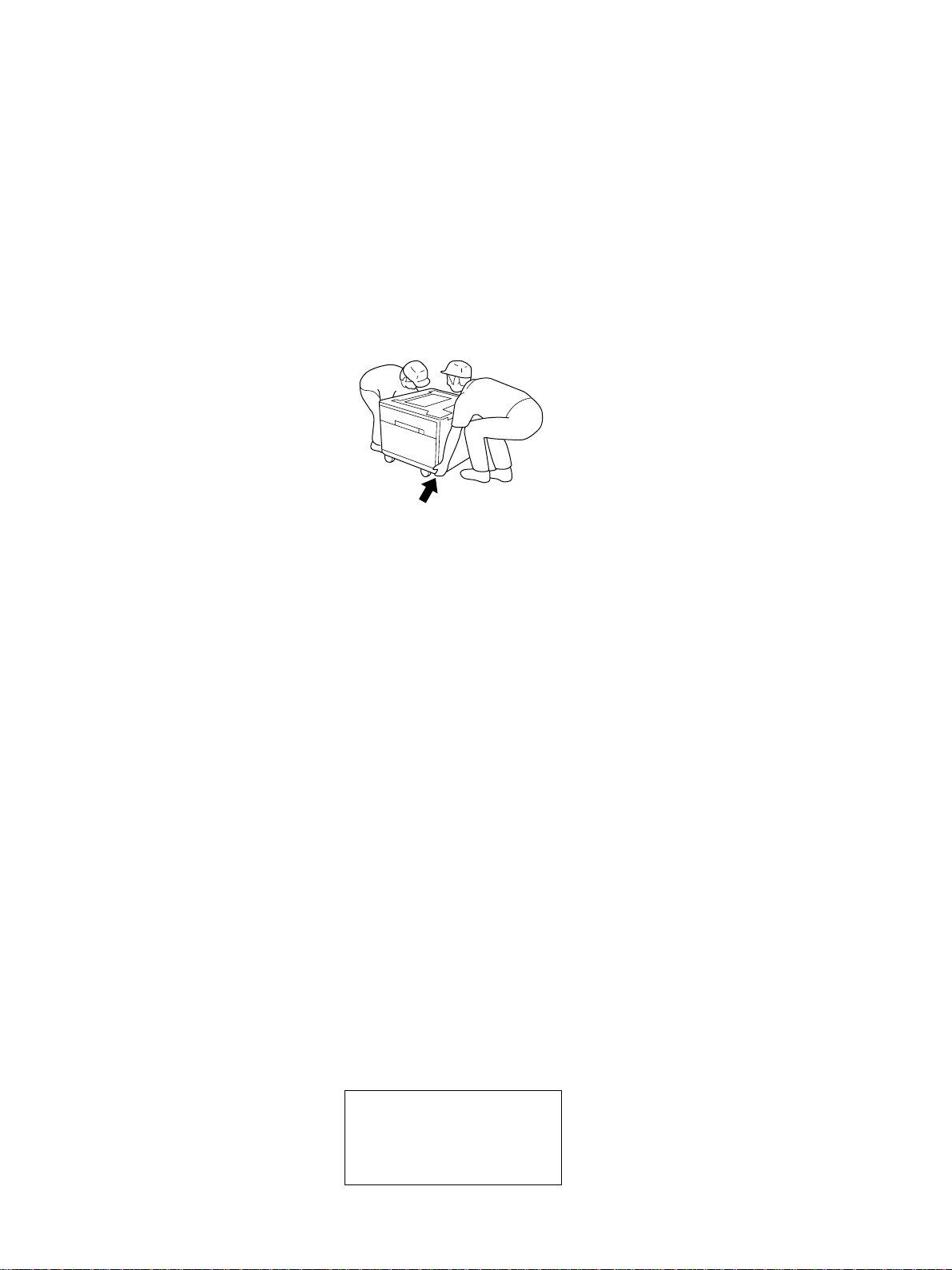
3. When transporting/installing the KD-1010, employ two persons and be sure to use the positions as
indicated below . The KD-1010 is f airly heavy and weights appro ximately 23 kg (51 lb), therefore pa y full
attention when handling it.
4. Before starting installation, servicing or maintenance work, be sure to turn off and unplug the copier
first.
5. The KD-1010 is supplied with power from the copier , requiring no additional power source.
6. The KD-1010 should be grounded to the specified positions on the machine frame.
7. When servicing or maintaining the KD-1010, be careful about the rotating or operating sections such as
gears, pulleys, sprockets, cams, belts, etc.
8. When parts are disassembled, reassembly is basically the rev erse of disassembly unless otherwise
noted in this manual or other related documents. Be careful not to reassemble small parts such as
screws, washers, pins, E-rings, toothed washers to the wrong places.
9. Basically, the machine should not be operated with any parts removed or disassemb led.
10. Delicate parts for preventing safety hazard problems (such as thermofuses, door switches sensors,
etc. if any) should be handled/installed/adjusted correctly.
11. During servicing or maintenance work, be sure to check the nameplate and other cautionary labels (if
any) to see if they are clean and firmly stuck. If not, take appropriate actions.
12. Use suitable measuring instruments and tools.
13. The PC board must be stored in an anti-electrostatic bag and handled carefully using a wristband,
because the ICs on it may be damaged due to static electricity.
Caution: Before using the wrist band, pull out the power cord plug of the copier and make sure that
there is no uninsulated objects in the vicinity.
14. For the recov ery and disposal of used KD-1010, consumable parts and packing materials, it is recommended that the relevant local regulations/rules should be followed.
© Copyright 2000
TOSHIBA TEC CORPORA TION
Page 2

CONTENTS
1. SPECIFICATIONS ......................................................................................... 1-1
2. OVERVIEW .................................................................................................... 2-1
2.1 Front Sectional Vie w ....................................................................................................... 2-1
2.2 Layout of Electrical Parts................................................................................................ 2-2
2.3 Electrical Parts ............................................................................................................... 2-4
2.4 Harness Diagram ............................................................................................................ 2- 6
2.5 Circuit Diagram ............................................................................................................... 2- 7
2.6 Installation of PC Board .................................................................................................. 2- 8
2.7 Timing Chart ................................................................................................................... 2- 9
3. GENERAL OPERATION ................................................................................ 3-1
3.1 Description of Operation ................................................................................................. 3-1
3.2 Error Detection................................................................................................................ 3- 3
3.3 Flow Chart ...................................................................................................................... 3- 4
4. DRIVE SYSTEM AND FEEDING OPERATION............................................. 4-1
4.1 Configuration and Drive System...................................................................................... 4-1
5. DISASSEMBLY AND REPLACEMENT ......................................................... 5-1
5.1 Top Co ver ....................................................................................................................... 5-1
5.2 Installation and Removal of LCF Cassette and Covers ................................................... 5-1
5.3 Paper Guides.................................................................................................................. 5- 3
5.4 Standby Side Paper Mis-stacking Sensor ....................................................................... 5-5
5.5 End Fence Home P osition Sensor/Standby Side Empty Sensor ..................................... 5-5
5.6 End Fence Stop P osition Sensor .................................................................................... 5-6
5.7 LCF Transport Motor Unit ................................................................................................ 5- 6
5.8 PC Board........................................................................................................................ 5-7
5.9 T ra y-up Motor/End Fence Motor...................................................................................... 5- 7
5.10 Feed Clutch/Transport Clutch.......................................................................................... 5- 7
5.11 Side Cover Open/Close Switch ....................................................................................... 5-8
5.12 Feeding Unit ................................................................................................................... 5- 8
5.13 Feeding Side Paper Stock Sensor/Tray Bottom Sensor................................................. 5-10
5.14 Cassette Detection Switch............................................................................................ 5-10
5.15 Disassembly for Supplies ............................................................................................. 5-10
6. PERIODIC MAINTENANCE .......................................................................... 6-1
October 2000 © TOSHIBA TEC I KD-1010 CONTENTS
Page 3

Page 4

1. SPECIFICATIONS
Feeding method T andem tra y
Paper Size: A4,L T
Thickness: 64 - 80g/m
Transportation speed Approx. 260mm/sec. (Model with a DP2500)
Approx. 400mm/sec. (Models with a DP4500/3500)
Capacity of cassette Stack height: 137.5mm
Dimensions 530 (W) X 536 (D) X 305 (H) mm
(627 (W) X 618 (D) X 305 (H) mm : Including the stabilizer)
Weight Approx. 23 kg
Po wer supply 5V , 24V (supplied from the copier)
2
October 2000 © TOSHIBA TEC 1 - 1 KD-1010 SPECIFICATION
Page 5

Page 6
2. OVERVIEW
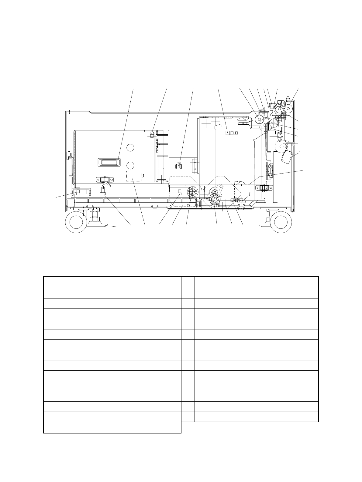
2.1 Front Sectional View
20
24 21 15 14 8 2 1 3 6 4
27
1312111817192225
26
5
7
9
10
23
16
NO. NAME NO . NAME
1 T r ay-up sensor (S3)
2 Feeding side paper empty sensor (S7)
3 Feed sensor (S2)
4 Side cover roller
5 T ransport roller
6 Feed roller
7 Separation roller
8 Pickup roller
9 Feed clutch (C2)
10 T ransport clutch (C1)
11 T ray-up coupling
12 T ray-up motor (M2)
1 3 Tray bottom sensor (S4)
1 5 Cassette detection switch (S10)
1 6 Elevator tray
1 7 End fence motor (M3)
18 End fence coupling
1 9 End fence stop position sensor (S5)
2 0 End fence home position sensor (S6)
2 1 Standby side paper mis-stacking sensor (S11)
2 2 Standby side empty sensor (S8)
2 3 Side cover open/close switch (S1)
24 Drawer connector
25 Adjuster
26 Pickup solenoid (SOL1)
27 End fence solenoid (SOL2)
1 4 Feeding side paper stock sensor (S9)
October 2000 © TOSHIBA TEC 2 - 1 KD-1010 OVERVIEW
Page 7
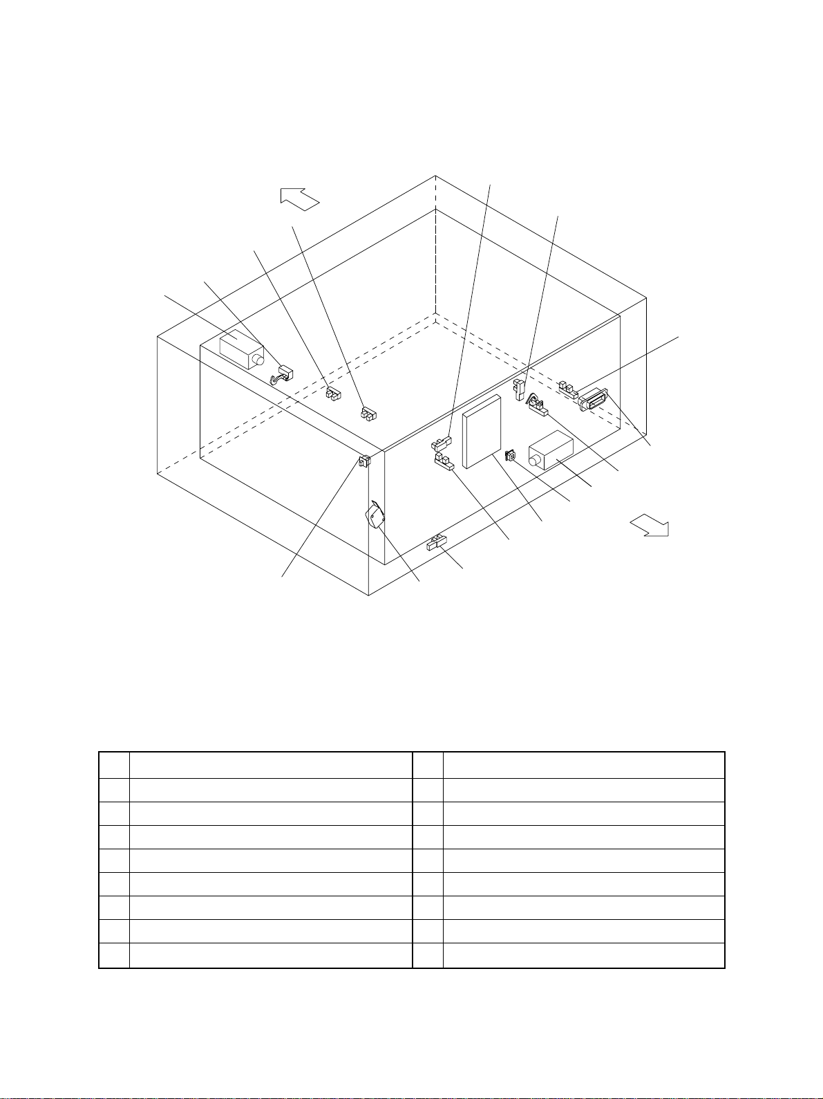
2.2 Layout of Electrical Parts
14
Front Side
1
2
3
4
12
11
13
10
15
8
16
9
Rear Side
7
6
5
NO . NAME NO . NAME
1 Tray-up sensor (S3)
2 Feeding side paper empty sensor (S7)
3 Feed sensor (S2)
4 Feeding side paper stock sensor (S9)
5 Tray bottom sensor (S4)
6 Side cover open/close switch <24V> (S1)
7 Side cover open/close switch <5V>
8 Cassette detection switch (S10)
9 End fence stop position sensor (S5)
1 0 Standby side empty sensor (S8)
1 1 End fence home position sensor (S6)
1 2 Standby side paper mis-stacking sensor (S11)
13 Drawer connector
14 Pickup solenoid (SOL1)
15 End fence solenoid (SOL2)
16 PC board (PWA)
KD-1010 OVERVIEW 2 - 2 October 2000 © TOSHIBA TEC
Page 8
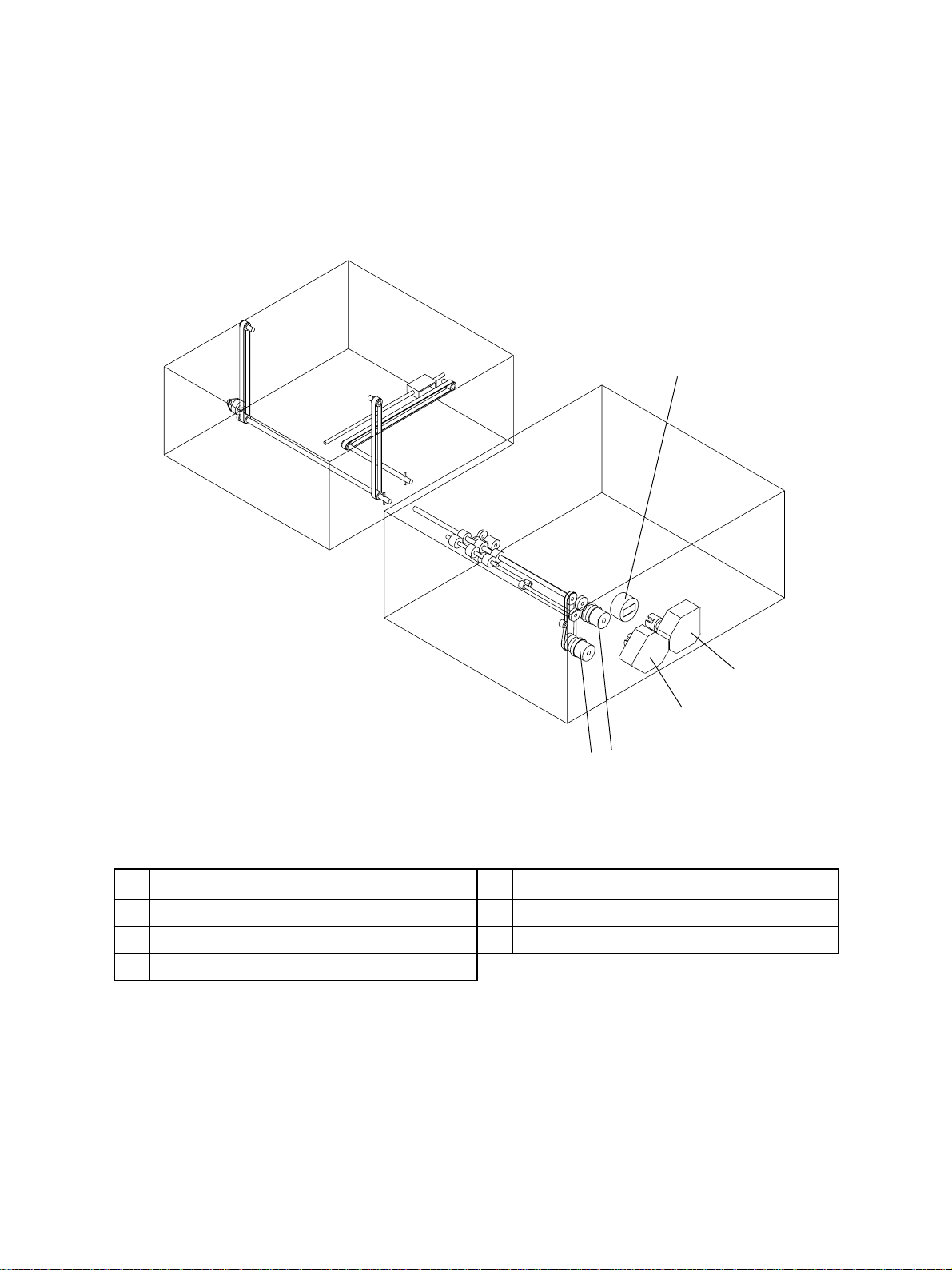
LCF
Cassette
1
LCF
2
3
4
5
NO. NAME NO. NAME
1 LCF transport motor (M1)
2 End fence motor (M3)
4 Feed clutch (C2)
5 Transport clutch (C1)
3 Tray-up motor (M2)
October 2000 © TOSHIBA TEC 2 - 3 KD-1010 OVERVIEW
Page 9

2.3 Electrical Parts
(1) Motor
SYMBOL NAME FUNCTION REMARKS
(M1) LCF-MTR Drives feeding and Brushless motor
LCF transport motor transportation
(M2) T -UP-MTR Lifts up the elevator tray Brush motor
Tray-up motor
(M3) END-F-MTR Drives the movement of the end Brush motor
End fence motor fence
(2) Electromagnetic clutch
SYMBOL NAME FUNCTION REMARKS
(C1) TR-CL T Drives the transportation
Transport clutch
(C2) FED-CL T Drives the roller to pick up
Feed clutch from the elevator tray
(3) Switches or sensors
SYMBOL NAME FUNCTION REMARKS
(S1) SIDE-COV -SW Side cover open/close Push switch
Side cover open/close switch detection
(S2) FED-SNR Detects paper from the Photo interrupter
Feed sensor elevator tray
(S3) T OP-SNR Detects if the elevator Photo interrupter
Tray-up sensor tray has been raised
(S4) TRY-BTM-SNR Detects the home position Photo interrupter
Tray bottom sensor of the elevator tray
(S5) END-F-STP-SNR Detects the stop position Photo interrupter
End fence stop position sensor of the end fence
(S6) END-F-HP-SNR Detects the home position Photo interrupter
End fence home position sensor of the end fence
(S7) EMP-SNR-FS Detects lack of paper Photo interrupter
Feeding side paper empty sensor of the feed side
(S8) EMP-SNR-SS Detects lack of paper Photo interrupter
Standby side paper empty sensor of the standby side
(S9) PST -SNR-FS Detects that the paper Photo interrupter
Feeding side paper stock sensor stock is going short
(S10) CST-SW Detects the availability Push switch
Cassette detection switch of the cassette
(S11) PR-MST-SS Detects mis-stacking of paper Photo interrupter
Standby side paper mis-stacking sensor in the standby side cassette
KD-1010 OVERVIEW 2 - 4 October 2000 © TOSHIBA TEC
Page 10

(4) PC Board
SYMBOL NAME FUNCTION REMARKS
PWA PW A-F-PFP-523 Drives the feeding and moves
PC board the tray
(5) Solenoids
SYMBOL NAME FUNCTION REMARKS
(SOL1) PICKUP-SOL Lifts up the pickup roller
Pickup solenoid
(SOL2) END-F-SOL Moves the lever to detect mis-
End fence solenoid stacking of paper in the standby
side cassette
October 2000 © TOSHIBA TEC 2 - 5 KD-1010 OVERVIEW
Page 11

KD-1010 OVERVIEW 2 - 6 October 2000 © TOSHIBA TEC
Page 12
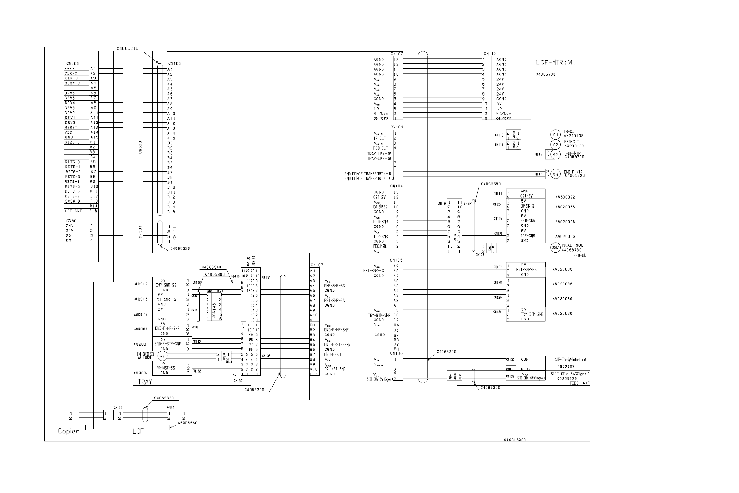
2.4 Harness Diagram
October 2000 © TOSHIBA TEC 2 - 7 KD-1010 OVERVIEW
Page 13
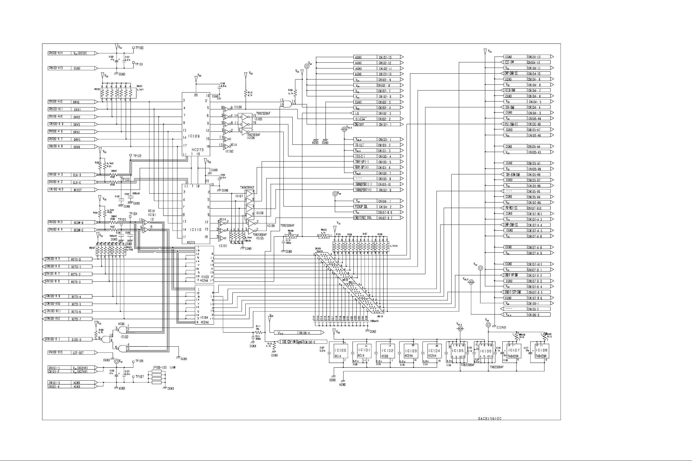
2.5 Circuit Diagram
KD-1010 OVERVIEW 2 - 8 October 2000 © TOSHIBA TEC
Page 14

2.6 Installation of PC Board
October 2000 © TOSHIBA TEC 2 - 9 KD-1010 OVERVIEW
Page 15

2.7 Timing Chart
(1 ) DP2500 (A4 sized sheet fed from the LCF)
KD-1010 OVERVIEW 2 - 10 October 2000 © TOSHIBA TEC
Page 16

(2 ) DP4500/3500 (A4 sized sheet fed from the LCF)
October 2000 © TOSHIBA TEC 2 - 11 KD-1010 OVERVIEW
Page 17

Page 18

3. GENERAL OPERATION
3.1 Description of Operation
[A] From power ON to standby
(1) When the copier is turned ON, power is also supplied to the feeding unit to start the pre-running
operation. The tray-up motor (M2) starts to rotate forw ard and raises the tray. The tr ay-up motor (M2) is
turned OFF when the tray turns ON the tray-up sensor (S3), then the tray is stopped. At this time, it is
judged that there is paper in the feeding side cassette when the feeding side empty sensor (S7) is ON.
On the other hand, the absence of paper in the feeding side cassette is assumed when the sensor (S7)
is OFF, and the standby side empty sensor (S8) is subsequently checked. When the standby side
empty sensor (S8) is OFF, that means that paper is absent in the standby side cassette, and it is
therefore assumed that there is no paper in the LCF. When the standby side empty sensor (S8) is ON,
the paper in the standby side cassette is mov ed to the f eeding side cassette . The tray-up motor (M2)
is rotated in rev erse and lowers the tra y of the feeding side . The lowered tra y turns ON the tray bottom
sensor (S4), and the tray-up motor (M2) is turned OFF to stop the tray. The end fence solenoid and
pickup solenoid are then turned ON. The end fence motor (M3) rotates forward and the paper in the
standby side cassette is mov ed onto the tray of the f eeding side. The end fence motor (M3) is stopped
for a second when the end fence stop position sensor (S5) is turned ON, and the motor (M3) immediately starts to rotate in reverse to return the end fence to the position where the home position sensor
(S6) is turned ON. When the returning operation is started, the end fence solenoid and pickup solenoid
are turned OFF, and the tray-up motor (M2) is rotated forward to r aise the tra y . The tr ay-up motor (M2)
is turned OFF when the tray being raised turns ON the tray-up sensor (S3) and stops the tr a y. At this
time, the presence of paper is judged when the feeding side empty sensor (S7) is ON.
(2 ) If the power is turned ON when the cassette has been removed, the tray-up motor for that cassette is
not turned ON. The tray is raised as soon as the cassette is installed, and it detects if there is paper
in the cassette.
(3) If either of the feed sensor (S2) is ON (there is paper in the transportation path) when the power is
turned ON, that means a paper jam has occurred and the operation is disabled until the paper is
removed.
October 2000 © TOSHIBA TEC 3 - 1 KD-1010 GENERAL OPERATION
Page 19

[B] Standby status
(1 ) T ra ys detect the paper as described abov e, and the copier goes into the standb y status .
(2 ) The tray goes down automatically when the cassette is removed and is raised as soon as the cassette
is reinstalled it then checks if there is paper in the cassette.
[C] From the start to the end of copying
(1 ) The main motor of the copier is turned ON when the START ke y is pressed. The LCF transport motor
(M1) are turned ON to drive.
(2 ) When the copier judges that the LCF is ready f or f eeding paper , it turns ON the feed clutch (C2) of the
selected cassette. This clutch drives the pic kup roller and feed roller to feed paper from the tra y.
(3 ) About 0.02 sec (DP4500/3500: 0.05 sec), after the feeding started transport clutch (C1) are turned ON
to drive the transport roller.
(4 ) The leading edge of the paper turns the feed sensor (S2) ON. These are located right ne xt to the e xit
side of the selected cassette. The feed clutch (C2) is turned OFF and feeding from the cassette is
completed.
(5 ) The paper is tr ansported to the copier by the LCF transport roller. If the trailing edge of the pre viously
sent sheet still remains at the feed sensor when the leading edge of the paper reaches the feed sensor
(S2), the transport clutch (C1) is turned OFF to stop the transport of the paper.
(6 ) The trailing edge of the paper turns the feed sensor (S2) OFF. These are located right next to the exit
side of the selected cassette. LCF then becomes ready for feeding the next sheet of paper, and the
procedures (2) to (5) are repeated.
(7) When the copying operation is completed, the main motor, LCF transport motor (M1) and transport
clutch (C1) are turned OFF and the transport roller is stopped.
KD-1010 GENERAL OPERATION 3 - 2 October 2000 © TOSHIBA TEC
Page 20

3.2 Error Detection
[A] Jam detection
(1 ) A paper jam (E19, E33, E36) [DP4500/3500: (E19, E3C, E3D, E3E)] occurs in the following cases.
a. Feed sensor (S2) is not turned ON within 0.5 seconds after the feeding is started.
b . The leading edge of the paper does not pass the feed sensor (S2) in the transport path within a fixed
time.
(2 ) Open the side co ver of the paper feeder and remo ve all the paper remaining on the transport path and
close the side cover to clear the jammed paper. If either of the f eed sensors (S2) is still ON when the
side cover is closed, it is determined that there is still paper on the transport path and the paper jam
status is not canceled.
(3 ) When a paper jam occurs in the paper feeder during multiple copying, the sheet that was fed before the
jam is copied normally .
[B] Call Service
(1 ) When the tray-up sensor (S3) is not turned ON even through 8 seconds (DP4500/3500: 10 seconds)
have passed since the tr ay started to be raised, it is assumed that the cassette cannot be used (there
is no paper) and the corresponding message is displayed on the control panel.
(2) When the tray bottom sensor (S4) is not turned ON even through 8 seconds (DP4500/3500: 10 seconds)
have passed since the tray started to be lowered, it is assumed that the cassette cannot be used
(there is no paper) and the corresponding message is displayed on the control panel.
(3) When the end fence stop position sensor (S5) is not turned ON even through 8 (DP4500/3500: 5
seconds) seconds have passed since the end fence started to move the paper in the standby side
cassette, it is assumed that the cassette cannot be used (there is no paper) and the corresponding
message is displayed on the control panel.
(4) When the end fence home position sensor (S6) is not turned ON even through 8 seconds (DP4500/
3500: 5 seconds) ha ve passed since the end f ence started to move the paper in the standby side , it is
assumed that the cassette cannot be used (there is no paper) and the corresponding message is
displayed on the control panel.
(5 ) The states (1) to (4) are cleared by removing the cassette.
October 2000 © TOSHIBA TEC 3 - 3 KD-1010 GENERAL OPERATION
Page 21
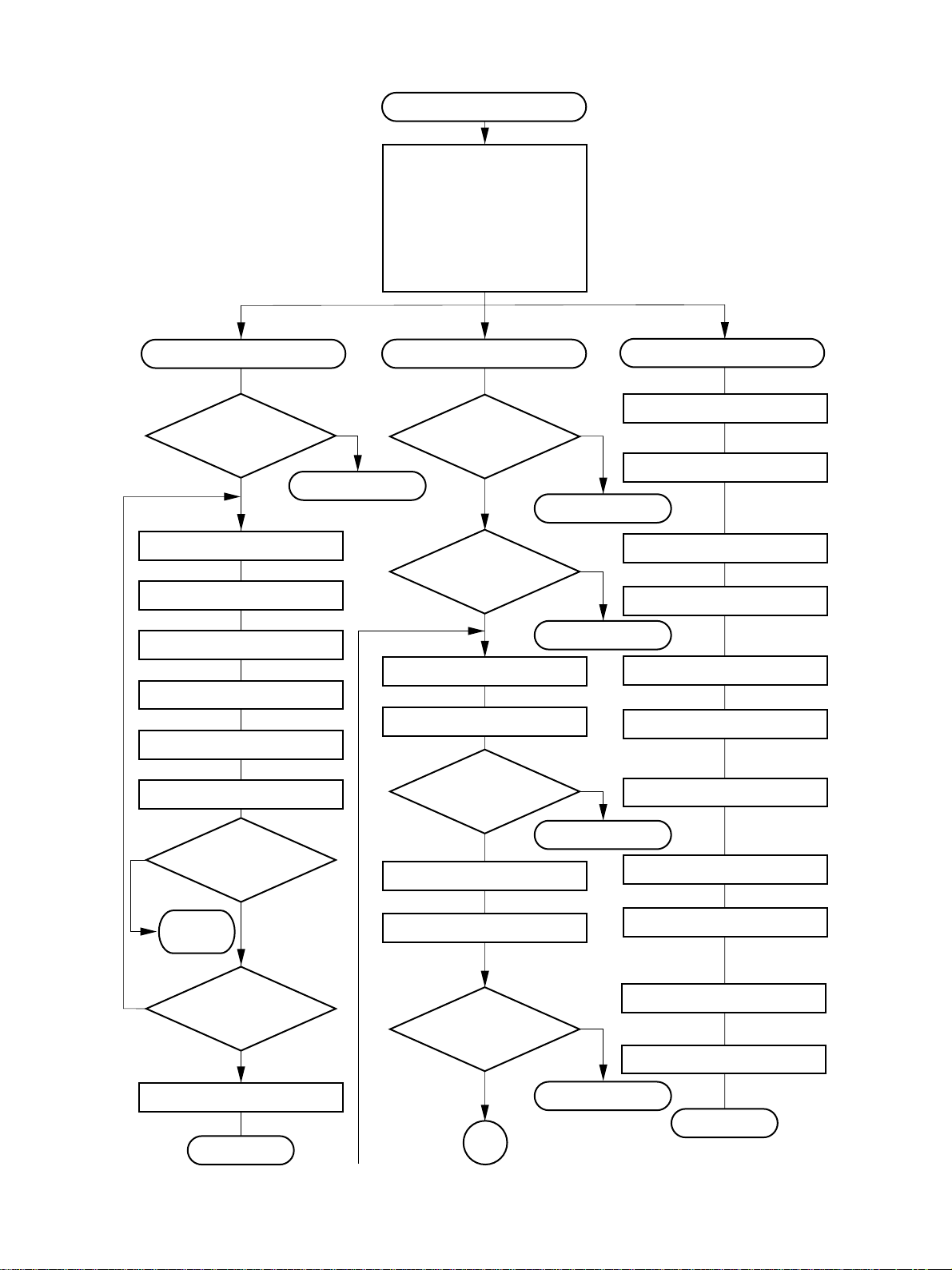
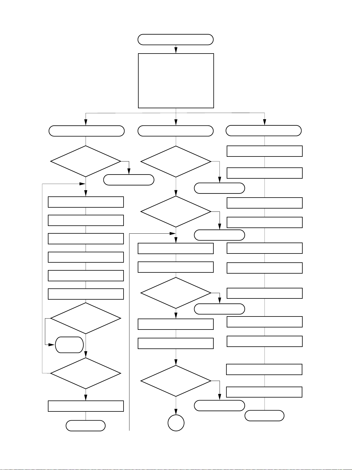
3.3 Flow Chart
(1) DP2500
START key ON
Main motor ON
LCF transport motor ON
Polygonal motor ON
Developer bias ON
Separation charger ON
Main charger ON
Discharge lamp ON
Processing control
Polygonal motor
rotating normally?
YES
Call for Service
Laser ON
Transfer charger ON
Transfer guide bias ON
Laser OFF
Transfer charger OFF
Transfer-guide bias OFF
NO
"CA1"
Transpor t system control
Main motor
rotating normally?
YES
LCF transport
motor rotating
normally?
YES
LCF feed clutch ON
LCF transport clutch ON
LCF feed
sensor ON?
Carriages move backward
NO
Call for Service
"C01"
NO
Call for Service
"C1B "
NO
Scanner system control
Black shading
Exposure lamp ON
Carriages Stopped
Carriages move forward
White shading
Scanning
NO
H-Sync OK?
Call for
Service
YES
LCF feed clutch OFF
YES
Copier’s transport clutch ON
Paper jam
"E19"
Carriages stopped
Exposure lamp OFF
"CA2"
NO
Remaining number
of copies=0?
Copier’s feed
NO
Carriages move backward
sensor ON?
YES
Polygonal motor OFF
YES
Paper jam
"E36"
Processing con-
trol completed
KD-1010 GENERAL OPERATION 3 - 4 October 2000 © TOSHIBA TEC
B
Carriages stopped
Scanner system
control completed
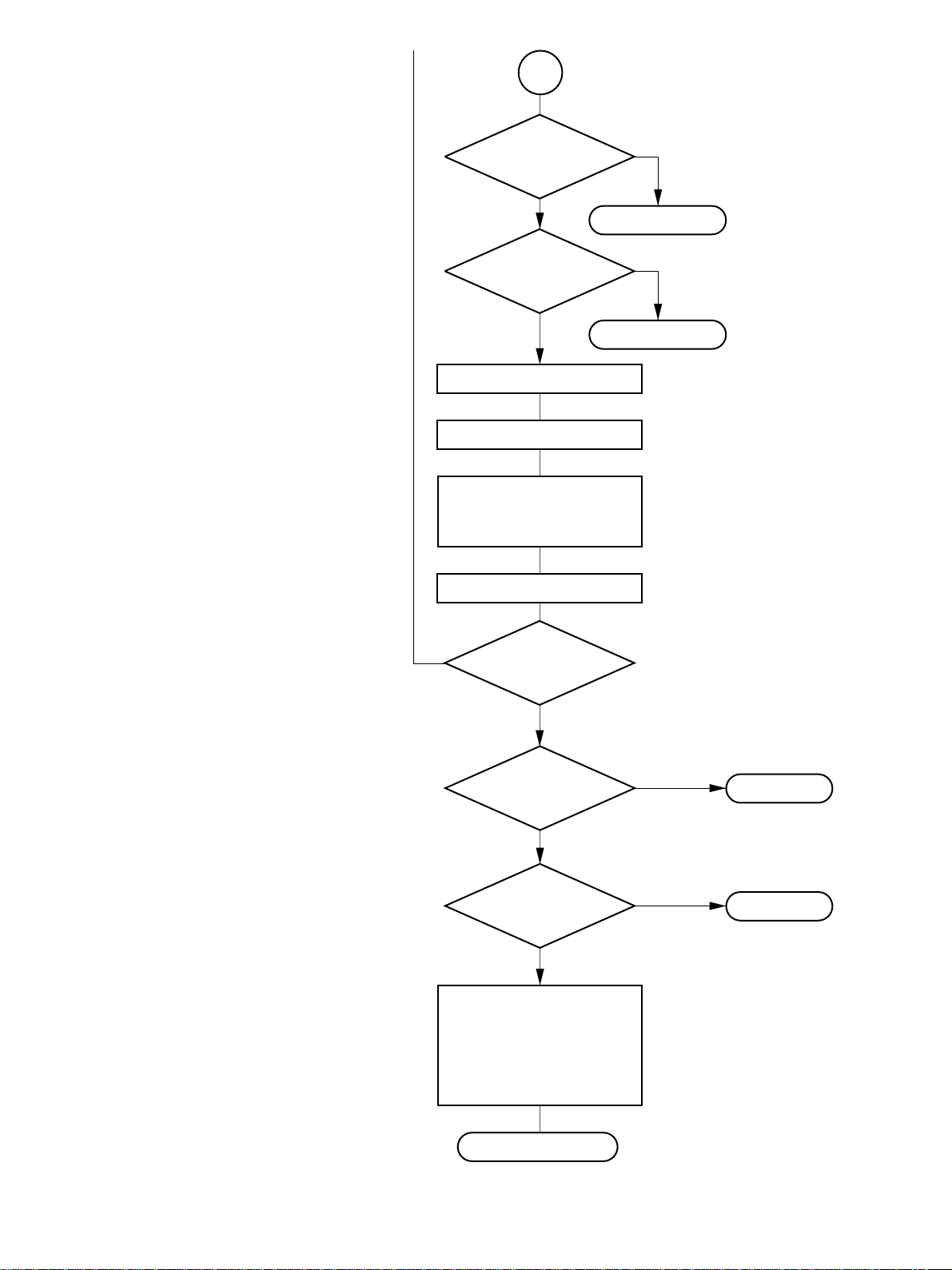
Page 22
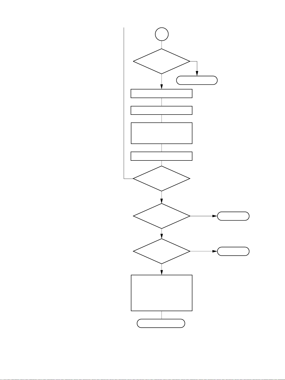
B
Copier’s registration
sensor ON?
YES
LCF transport clutch OFF
Copier’s transport clutch OFF
Copier’s registration clutch ON
Copier’s transport clutch ON (Low)
Counter ON
Copier’s registration clutch OFF
NO
Remaining number
of copies = 0?
YES
NO
Paper jam
"E33"
Exit
sensor 1
ON?
YES
Exit
sensor 2
ON?
YES
Main charger OFF
Main motor OFF
LCF transport motor OFF
Developer bias OFF
Separation charger OFF
Discharge lamp OFF
Standby
NO
NO
Paper jam
"E01"
Paper jam
"E02"
October 2000 © TOSHIBA TEC 3 - 5 KD-1010 GENERAL OPERATION
Page 23
(2) DP4500/3500
START key ON
Main motor ON
LCF transport motor ON
Polygonal motor ON
Developer bias ON
Separation charger ON
Main charger ON
Discharge lamp ON
Processing control
Polygonal motor
rotating normally?
YES
Call for Service
Laser ON
Transfer charger ON
Transfer guide bias ON
Laser OFF
Transfer charger OFF
Transfer-guide bias OFF
NO
"CA1"
Transpor t system control
Main motor
rotating normally?
YES
LCF transport
motor rotating
normally?
YES
LCF feed clutch ON
LCF transport clutch ON
LCF feed
sensor ON?
Carriages move backward
NO
Call for Service
"C01"
NO
Call for Service
"C1B"
NO
Scanner system control
Black shading
Exposure lamp ON
Carriages Stopped
Carriages move forward
White shading
Scanning
NO
H-Sync OK?
Call for
Service
YES
LCF feed clutch OFF
YES
Copier’s transport clutch ON
Paper jam
"E19"
Carriages stopped
Exposure lamp OFF
"CA2"
NO
Remaining number
of copies=0?
Copier’s lower
NO
Carriages move backward
feed sensor ON?
YES
Polygonal motor OFF
YES
Paper jam
"E3E"
Processing con-
trol completed
KD-1010 GENERAL OPERATION 3 - 6 October 2000 © TOSHIBA TEC
B
Carriages stopped
Scanner system
control completed
Page 24
B
Copier’s upper feed
sensor ON?
YES
Paper jam
Copier’s registration
sensor ON?
YES
Paper jam
LCF transport clutch OFF
Copier’s transport clutch OFF
Copier’s registration clutch ON
Copier’s transport clutch ON (Low)
Counter ON
Copier’s registration clutch OFF
NO
"E3D"
NO
"E3C"
NO
Remaining number
of copies = 0?
Exit
sensor 1
ON?
Exit
sensor 2
ON?
Main charger OFF
Main motor OFF
LCF transport motor OFF
Developer bias OFF
Separation charger OFF
Discharge lamp OFF
YES
YES
YES
NO
NO
Paper jam
"E01"
Paper jam
"E02"
Standby
October 2000 © TOSHIBA TEC 3 - 7 KD-1010 GENERAL OPERATION
Page 25

Page 26

4. DRIVE SYSTEM AND FEEDING OPERATION
4.1 Configuration and Drive System
The Large Capacity Feeder (LCF) mainly consists of the LCF cassette, pic kup roller, f eed roller, separ ation
roller, tr ansport roller and drive system for these components.
• Feeding/Transport system
The LCF transport motor drives the pickup roller, f eed roller , separation roller and transport roller which
are located in the feeding area.
• Cassette tray system
This system raises and lowers the tray.
• End fence system
This system movement of the end fence.
Feed roller
LCF cassette
Transpor t roller
Pickup roller
LCF transport motor
LCF
End fence motor
Tray-up motor
Feed clutch
Transpor t clutch
October 2000 © TOSHIBA TEC 4 - 1 KD-1010 DRIVE SYSTEM
Page 27

Page 28

5.
Disassembly and Replacement
5.1 Top cover
Remove 5 screws and take off the top cover.
5.2 Installation and Removal of the LCF
Cassette and Covers
[A] LCF cassette
(1 ) Draw out the LCF cassette toward you.
(2) Remove one screw and take off the stopper
bracket at the left side of the LCF cassette.
Top cover
Stopper bracket
(3) Pull out the LCF cassette while pressing the plate
spring at the right side of the LCF cassette.
[B] Front cover
Remove 2 scre ws and tak e off the front cover.
LCF cassette
Plate spring
October 2000 © TOSHIBA TEC 5 - 1 KD-1010 DISASSEMBLE/REPLACE
Page 29

[C] Rear cover
Remove 3 scre ws and tak e off the rear co v er.
[D] Feeding side rear cover
Remove 2 screws and take off the feeding side
rear cover .
[E] Feeding side front cover
Remove 2 screws and take off the feeding side
front cover.
[F] Side cover
(1 ) Open the side cover and take the protrusion at
the front side of the side cover out of the hole of
the frame while pushing the cover to the rear
side.
(2) Remove the side cover.
Feeding side rear cover
Front side
Feeding side front cover
Rear side
Fulcrum of the front side
KD-1010 DISASSEMBLE/REPLACE 5 - 2 October 2000 © TOSHIBA TEC
Page 30

5.3 Paper Guides
[A] Feeding side front guide
(1 ) Remove one screw fixing the feeding side front
guide.
(2 ) Lift up the paper guide slightly and place it into
the slots for the appropriate size. Confirm the
position of the screwhole and insert a screw into
it.
Punch mark
[B] Feeding side rear guide
(1 ) Remove one screw fixing the feeding side rear
guide.
(2 ) Lift up the paper guide slightly and place it into
the slots for the appropriate size. Confirm the
position of the screwhole, and insert a screw
into it.
LTA4
Punch mark
LT A4
October 2000 © TOSHIBA TEC 5 - 3 KD-1010 DISASSEMBLE/REPLACE
Page 31

[C] Standby side front guide
(1 ) Remove one screw fixing the standby side front
guide and slide the guide in the direction of the
arrow .
(2 ) Lift up the paper guide slightly and place it into
the slots for the appropriate size. Cconfirm the
position of the screw hole, and insert a screw
into it.
LT
A4
[D] Standby side rear guide
(1 ) Remove one screw fixing the standby side rear
guide and slide the guide in the direction of the
arrow .
(2 ) Lift up the paper guide slightly and place it into
the slots for the appropriate size. Confirm the
position of the screwhole, and insert a screw
into it.
Note: When the position of the standby side rear
guide is changed (A4−>LT or LT−>A4),
remember that the direction of the rear guide
stopper to be assembled is also changed
(See the following figure).
[A4 size] [LT size]
Rear guide
stopper
Fixing screw
Rear guide
stopper
Fixing screw
LT A4
KD-1010 DISASSEMBLE/REPLACE 5 - 4 October 2000 © TOSHIBA TEC
Page 32
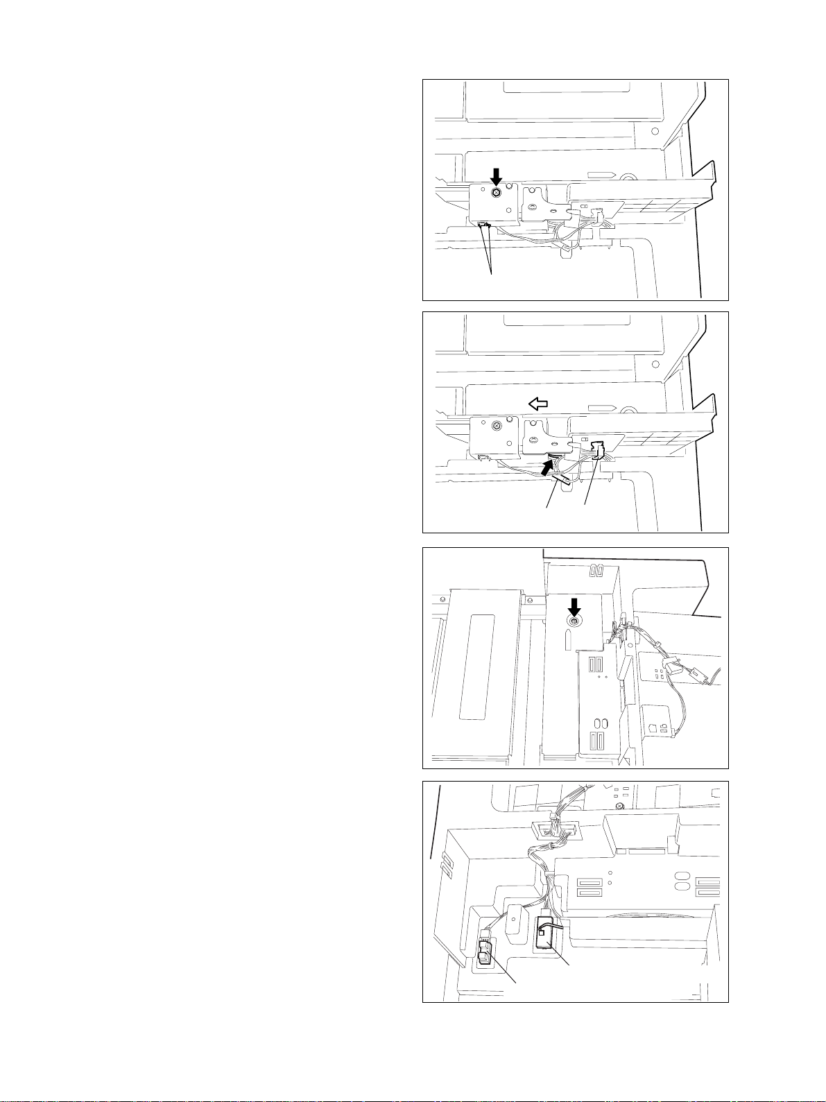
5.4 Standby side Paper Mis-stacking
Sensor
(1) Remove one screw and take off the sensor
bracket.
(2 ) Disconnect one connector.
(3 ) Release the latch and remove the sensor .
5.5 End Fence Home Position Sensor /
Standby Side Empty Sensor
(1 ) Disconnect one connector, and release the har-
ness from the clamp.
(2 ) Remove one screw fixing the standby side rear
guide, then slide the guide in the direction of the
arrow to take it out.
Latch
(3 ) Remove one screw and take off the bracket.
(4 ) Disconnect the connector.
(5) Release the latch to remove the end-fence home
position sensor and the standby side paper
empty sensor from the backside of the LCF cas-
sette.
Connector
Clamp
Standby side paper empty sensor
End fence home position sensor
October 2000 © TOSHIBA TEC 5 - 5 KD-1010 DISASSEMBLE/REPLACE
Page 33
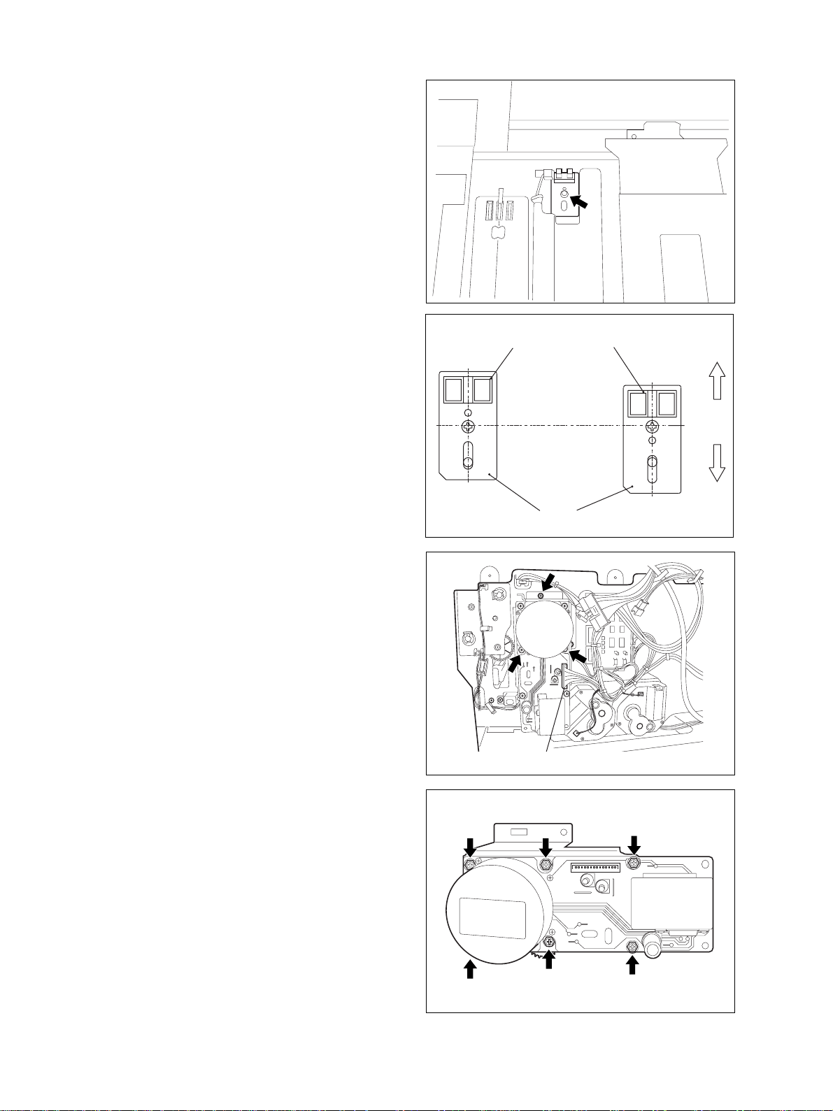
5.6 End Fence Stop Position Sensor
(1) Disconnect one connector, remove one screw
and take off the bracket.
(2 ) Release the latch to remove the sensor.
Note: The positions to attach the end fence stop
position sensor differ according to each
paper size.
5.7 LCF T ransport Motor Unit
(1 ) Disconnect one connector.
(2) Remove 3 screws and take off the LCF trans-
port motor along with the bracket.
[A4 size] [LT size]
End fence stop position
sensor
Bracket
Feeding side
Standby side
Connector
(3) Remove 6 screws and take off the motor from
the bracket.
KD-1010 DISASSEMBLE/REPLACE 5 - 6 October 2000 © TOSHIBA TEC
Page 34
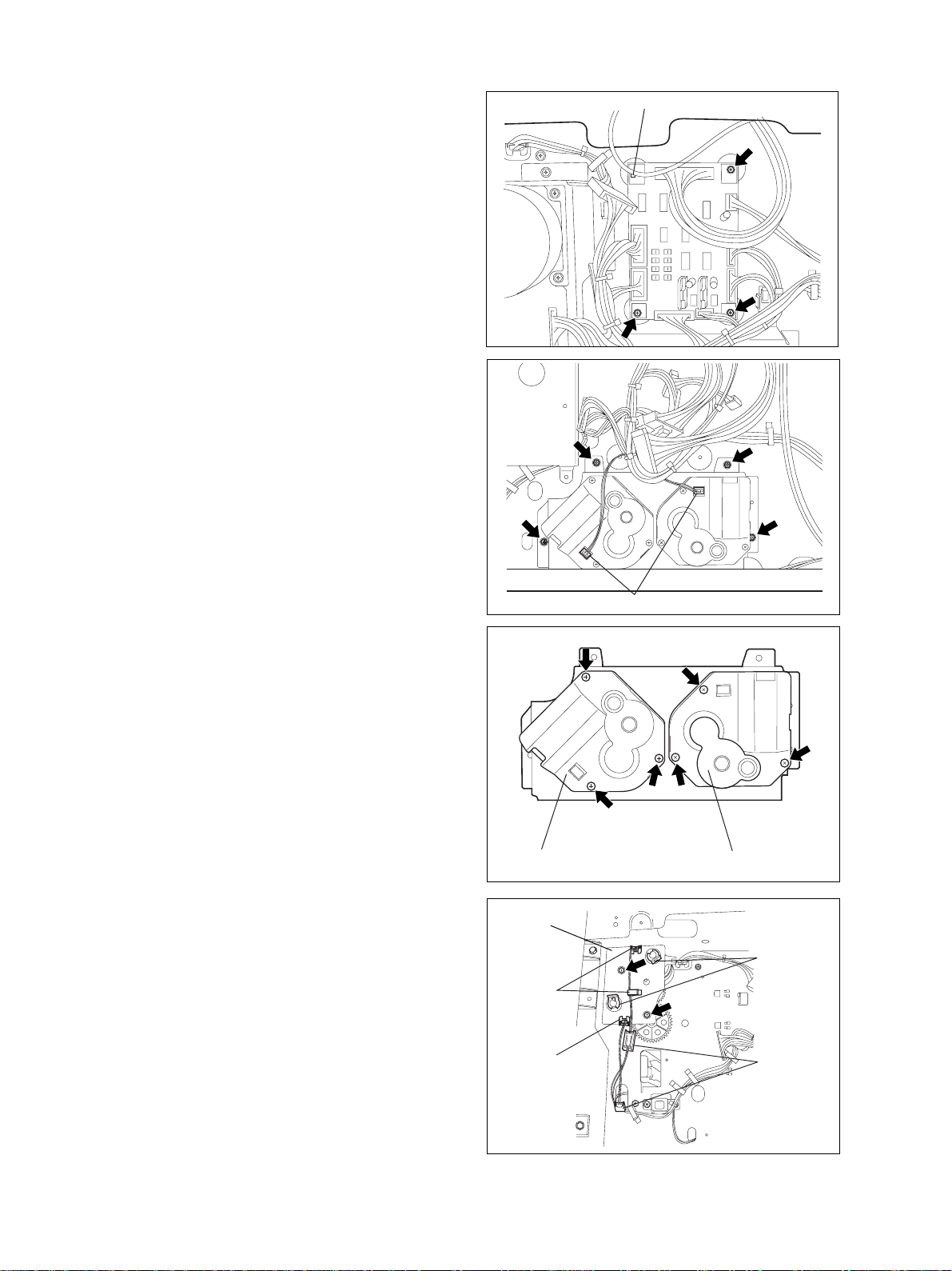
5.8 PC Board
(1 ) Disconnect 8 connectors.
(2) Remove one lock support and 3 screws. Take
off the PC board.
5.9 Tray-up Motor / End Fence Motor
(1 ) Disconnect 2 connectors.
(2) Remove 4 screws and take out the tray-up motor
/ end fence motor along with the bracket.
Lock support
(3 ) Remove 6 screws and take off the tray-up motor
and the end-fence motor to detach the motors
from the bracket.
5.10 Feed Clutch / Transport Clutch
(1 ) Relase the harness from 3 clamps and discon-
nect 2 connectors.
(2) Remove 2 clips and 2 screws. Take off the
bracket.
Connector
Tray-up motor
Bracket
Clamps
Clamp Connectors
End fence motor
Clips
October 2000 © TOSHIBA TEC 5 - 7 KD-1010 DISASSEMBLE/REPLACE
Page 35
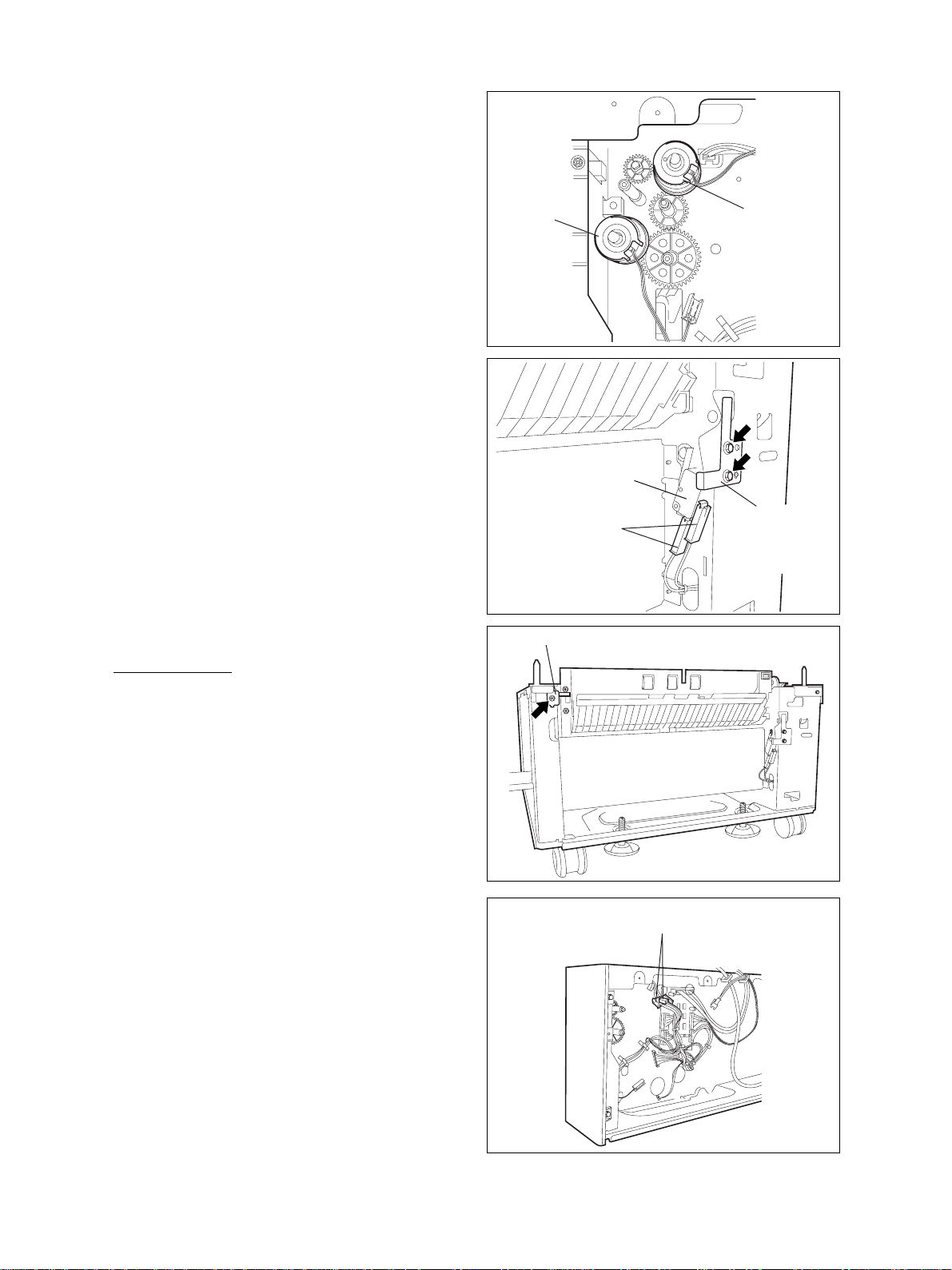
(3) Remove the feed clutch and transport clutch.
5.11 Side Cover Open/Close Switch
(1 ) Disconnect 2 connectors.
(2) Remove 2 screws and the plate spring for the
tension pulley.
(3 ) Remove the side cover open/close switch.
5.12 Feeding Unit
[A] Feeding unit
Transpor t
clutch
Slide cover open/
close switch
Connectors
Side cover open/close lock pin
Feed clutch
Plate spring of the
tension pulley
(1 ) Remove one screw and pull out the side cover
open/close lock pin for the feeding unit.
(2 ) Disconnect 2 connectors.
Connectors
KD-1010 DISASSEMBLE/REPLACE 5 - 8 October 2000 © TOSHIBA TEC
Page 36

(3 ) Release the latch from the groove on the shaft,
and take off the gear .
(4 ) Remove the clip and take off the belt to remove
the feeding unit drive gear .
(5) Remove 2 screws fixing the feeding unit, and
take off the unit upward while pushing it in the
direction of the arrow .
Feeding Unit drive gear
Clip
Gear
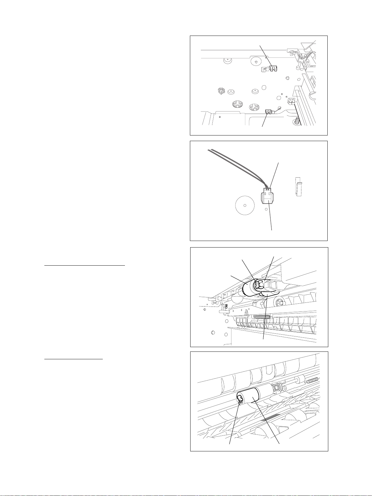
[B] Feed sensor
(1) Remove one screw and take off the sensor
bracket.
(2 ) Disconnect one connector and release the latch
to remove the sensor.
[C] Feeding side paper empty sensor / Tray-up sensor
(1) Disconnect the connectors of the sensor (one
each).
(2) Release the latches and remove the feeding side
paper empty sensor and the tray-up sensor .
Connector
Tray-up sensor
Latch
Feeding side paper
empty sensor
LatchLatch
October 2000 © TOSHIBA TEC 5 - 9 KD-1010 DISASSEMBLE/REPLACE
Page 37
5.13 Feeding Side Paper Stock Sensor
/ T r ay bottom sensor
(1 ) Disconnect the connectors of the sensor.
(2 ) Release the latch from the rear side and remove
the sensors toward the front side.
5.14 Cassette Detection Switch
Feeding side paper stock sensor
Tray bottom sensor
(1 ) Disconnect one connector.
(2 ) Release the latch and remove the switch toward
the front side.
5.15 Disassembly for Supplies
[A] Pickup roller/Feed roller
(1) Pull out the LCF cassette.
(2) Remove the clip and take off the pickup arm.
(3) Remove the pickup roller and feed roller from
the shaft.
Pickup roller
Connector
Cassette detection switch
Clip
Pickup arm
Feed roller
[B] Separation roller
(4 ) Open the side cover.
(5) Remove the clip and take off the separation roller .
Clip Separation roller
KD-1010 DISASSEMBLE/REPLACE 5 - 10 October 2000 © TOSHIBA TEC
Page 38
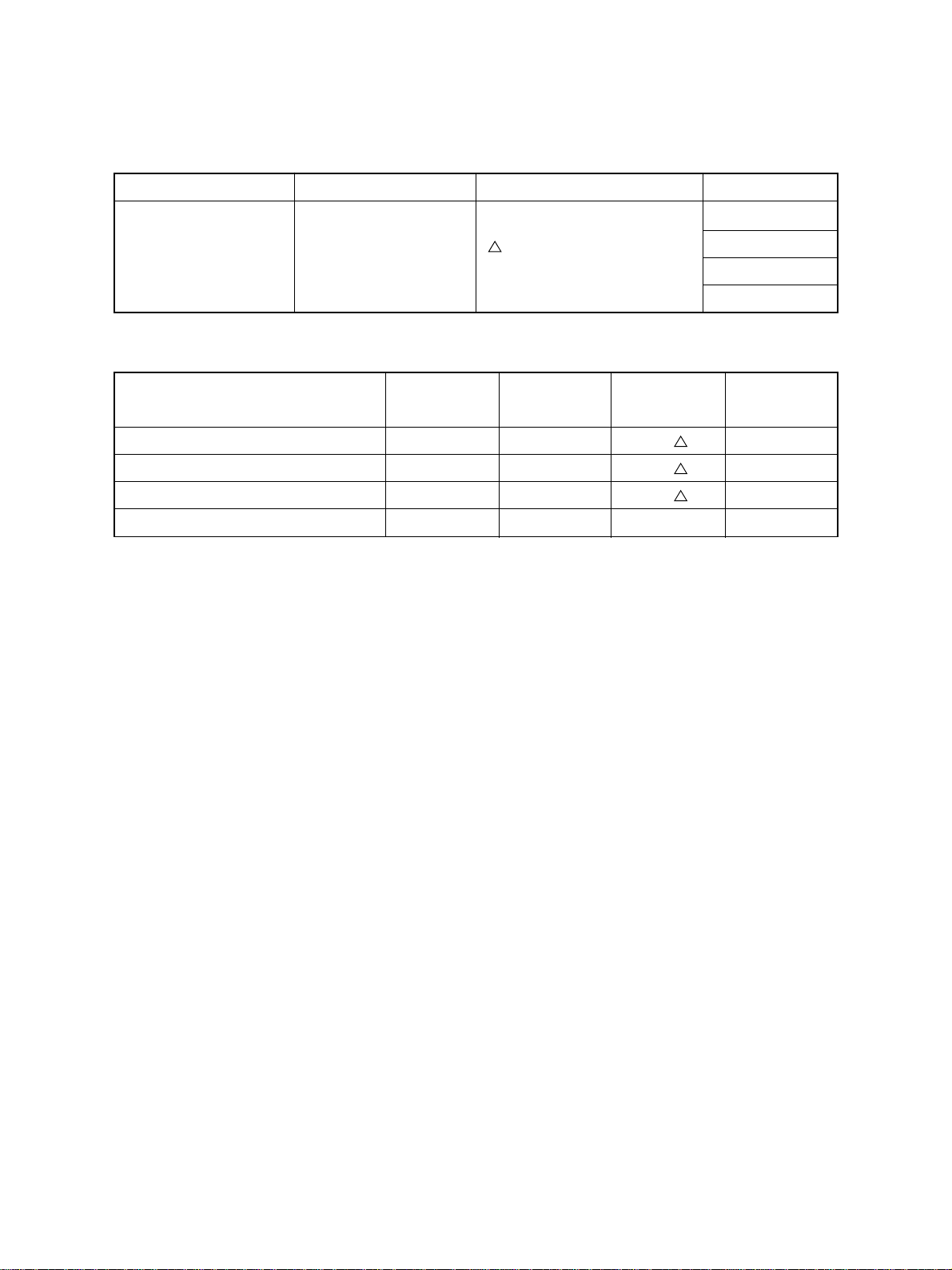
6. PERIODIC MAINTENANCE
Symbols used in the checklist
Cleaning Coating Replacing Date
A Cleaning with alcohol
General Maintenance Checklist
Item to inspect Cleaning Coating Replace every Remarks
Pickup roller(Upper/Lower) A 16 0
Feed roller(Upper/Lower) A 1 60
Separation roller(Upper/Lower) A 1 60
Drive gears(tooth face) W
*The above par ts are to be replaced depending on the number of the sheets of paper used in each
cassette.
W: White grease
(Molycoat)
A V: Alvania No. 2
8 0 Every 80K copies
Replace if deformed or
damaged
1K copies
User’s name
Serial No
Inspector’s name
Remarks
October 2000 © TOSHIBA TEC 6 - 1 KD-1010 PERIODIC MAINTENANCE
Page 39

MEMO
Page 40

MEMO
Page 41

MEMO
 Loading...