

Page 1
GENERAL PRECA UTIONS FOR INSTALLATION/SERVICING/
MAINTENANCE
1. When installing the Paper Feed Pedestal KD-1009 to the Copier, be sure to follow the instructions
described in the “Unpacking/Set-Up Procedure for the KD-1009” booklet which comes with each unit of
the KD-1009.
2. The KD-1009 should be installed by an authorized/qualified person.
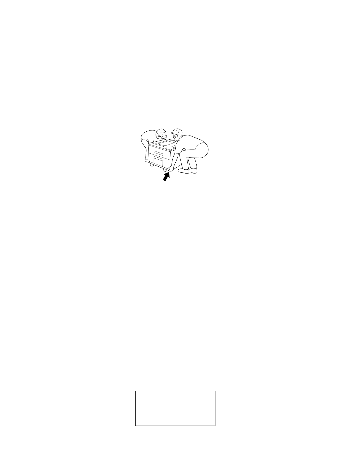
3. When transporting/installing KD-1009, employ two persons and be sure to use the positions as indicated below. KD-1009 is fairly heavy and weight approximately 17 kg (37.5 lb), therefore pay full
attention when handling it.
4. Before starting installation, servicing or maintenance work, be sure to turn off and unplug the copier
first.
5. The KD-1009 is supplied with power from the copier , requiring no additional power source.
6. The KD-1009 should be grounded to the specified positions on the machine frame.
7. When servicing or maintaining the KD-1009, be careful about the rotating or operating sections such as
gears, pulleys, sprockets, cams, belts, etc.
8. When parts are disassembled, reassembly is basically the reverse of disassembly unless otherwise
noted in this manual or other related documents. Be careful not to reassemble small parts such as
screws, washers, pins, E-rings, toothed washers to the wrong places.
9. Basically, the machine should not be operated with any parts removed or disassemb led.
10. Delicate parts for preventing safety hazard problems (such as thermofuses, door switches sensors,
etc. if any) should be handled/installed/adjusted correctly.
11. During servicing or maintenance work, be sure to check the nameplate and other cautionary labels (if
any) to see if they are clean and firmly stuck. If not, take appropriate actions.
12. Use suitable measuring instruments and tools.
13. The PC board must be stored in an anti-electrostatic bag and handled carefully using a wristband,
because the ICs on it may be damaged due to static electricity.
Caution: Before using the wrist band, pull out the power cord plug of the copier and make sure that
there is no uninsulated objects in the vicinity.
14. For the recov ery and disposal of used KD-1009, consumable parts and packing materials, it is recommended that the relevant local regulations/rules should be followed.
© Copyright 2000
TOSHIBA TEC CORPORA TION
Page 2

CONTENTS
1. SPECIFICATIONS ........................................................................................... 1-1
2. OVERVIEW ...................................................................................................... 2-1
2.1 Front Sectional Vie w ......................................................................................................... 2-1
2.2 Layout of Electrical Parts.................................................................................................. 2-2
2.3 Electrical Parts ................................................................................................................. 2-3
2.4 Harness Diagram .............................................................................................................. 2 -5
2.5 Circuit Diagram ................................................................................................................. 2- 9
2.6 Assembly of PC Board ..................................................................................................... 2- 12
2.7 Timing Chart ..................................................................................................................... 2-13
3. GENERAL OPERATION .................................................................................. 3-1
3.1 Description of Operation ................................................................................................... 3-1
3.2 Error Detection.................................................................................................................. 3- 2
3.3 Flow Chart .................................................................................................................. ...... 3- 3
4. DRIVE SYSTEM AND FEEDING OPERATION............................................... 4-1
4.1 Configuration and Drive System........................................................................................ 4- 1
5. DISASSEMBLY AND REPLACEMENT ........................................................... 5-1
5.1 Installation and Removal of Cassettes and Covers ........................................................... 5- 1
5.2 PC Board .......................................................................................................................... 5 -2
5.3 Upper and Lower Transport Roller (Plastic Rollers) ............................................................ 5-2
5.4 Motors .............................................................................................................................. 5-3
5.5 Feed/Separation/Pickup Roller .......................................................................................... 5 -4
5.6 Switches and Sensors ...................................................................................................... 5-6
6. PERIODIC MAINTENANCE ............................................................................ 6-1
October 2000 © TOSHIBA TEC I KD-1009 CONTENTS
Page 3

Page 4

1. SPECIFICATIONS
Feeding method Automatic feeding: 1 cassette installed from the front
(One extra cassette (option) are available for the models with a DP2500, DP4500/
3500)
Paper Size: A5 – A3
Thickness: 64 – 80g/m
Transportation speed Approx. 260mm/sec. (Models with a DP1600/2500)
Approx. 400mm/sec. (Models with a DP4500/3500)
Capacity of cassette Stack height: 60.5mm (approx. 550 sheets)
Dimensions 530 (W) × 536 (D) × 305 (H) mm
Weight Approx. 17 kg (one cassette)
Po wer supply 5V, 24V (supplied from the copier)
2
October 2000 © TOSHIBA TEC 1 - 1 KD-1009 SPECIFICATION
Page 5

Page 6
2. OVERVIEW
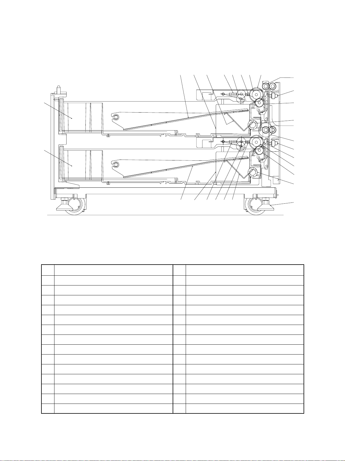
2.1 Front Sectional View
10
16 17
8
9
15
261823192524
12
56
4
3
7
12
13
14
11
20
21
22
27
28
NO . NAME NO. NAME
1 Upper cassette tray-up sensor (S4)
2 Upper cassette paper empty sensor (S6)
3 Upper feed sensor (S2)
4 Upper transport roller
5 Upper cassette feed clutch (C2)
6 Upper cassette feed roller
7 Upper cassette separation roller
8 Upper cassette
9 Lower cassette
10 Upper cassette tray-up motor (M2)
11 Lower feed sensor (S3)
12 Upper cassette elevator coupling
13 Lower transport roller
14 T ransport clutch (C1)
October 2000 © TOSHIBA TEC 2 - 1 KD-1009 OVERVIEW
1 5 Upper cassette pickup roller
1 6 Upper cassette tray
17 Upper cassette elevator
18 Lower cassette tray-up sensor (S5)
1 9 Lower cassette paper empty sensor (S7)
2 0 Lower cassette feed clutch (C3)
21 Lower cassette feed roller
22 Lower cassette separation roller
2 3 Lower cassette pickup roller
2 4 Lower cassette tray
25 Lower cassette tray-up motor (M3)
26 Lower cassette elevator
27 Lower cassette elevator coupling
28 Adjuster
Page 7
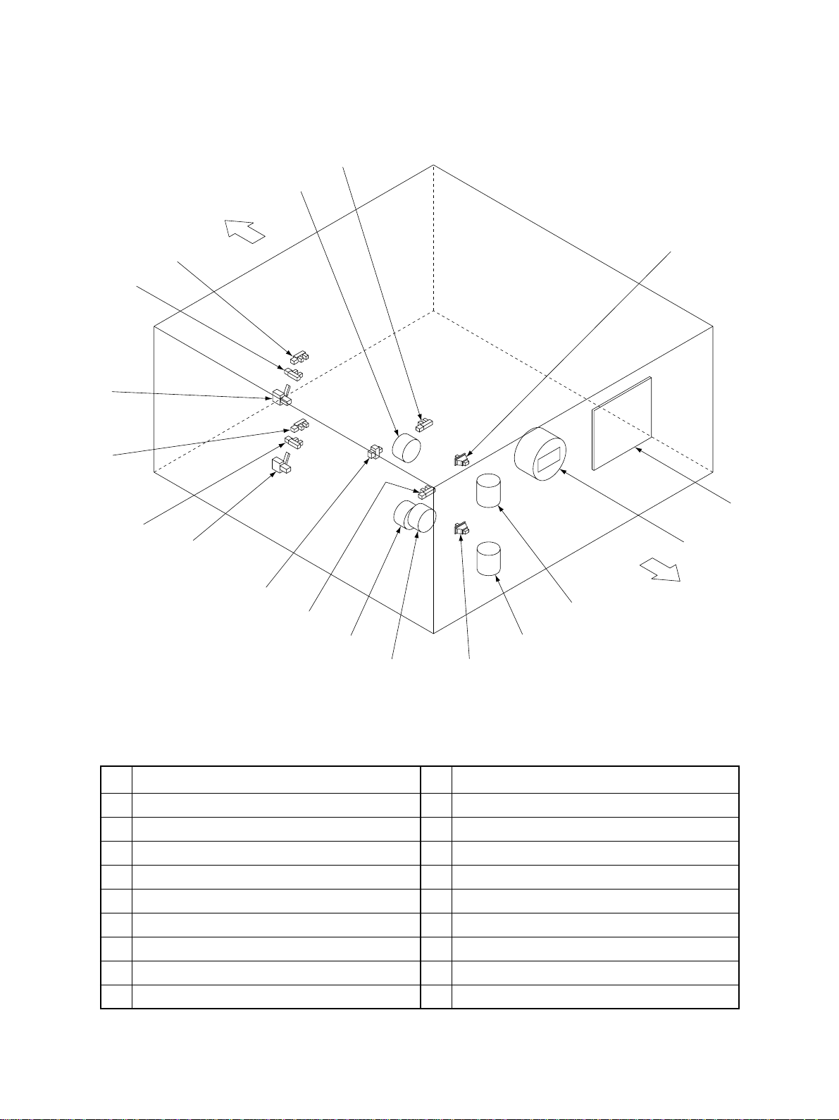
2.2 Layout of Electrical Parts
*
16
Front side
8
2
6
4
9
18
7
11
5
15
1
*
17
12
10
NO. NAME NO. NAME
1 Side cover open/close switch (S1)
2 Upper cassette detection switch (S8)
3 Lower cassette detection switch (S9)
4 Upper feed sensor (S2)
5 Lower feed sensor (S3)
6 Upper cassette tray-up sensor (S4)
7 Lower cassette tray-up sensor (S5)
8 Upper cassette paper empty sensor (S6)
9 Lower cassette paper empty sensor (S7)
*16 Upper cassette paper stock sensor (S10)
*17 Lower cassette paper stock sensor (S11)
3
10 T ransport clutch (C1)
1 1 Upper cassette feed clutch (C2)
1 2 Lower cassette feed clutch (C3)
13 Upper cassette tray-up motor (M2)
14 Lower cassette tray-up motor (M3)
1 5 PFP motor (M1)
18 PC board (PWA)
14
13
* for the DP4500/3500 only
Rear side
KD-1009 OVERVIEW 2 - 2 October 2000 © TOSHIBA TEC
Page 8

2.3 Electrical Parts
(1) Motor
SYMBOL NAME FUNCTION REMARKS
(M1) PFP-MTR Drives feeding and trans- Brushless motor
PFP motor portation
(M2) T-UP-U-MTR Lifts up the upper cassette tray Brush motor
Upper cassette tray-up motor
(M3) T-UP-L-MTR Lifts up the lower cassette tray Brush motor
Lower cassette tray-up motor
(2) Electromagnetic clutch
SYMBOL NAME FUNCTION REMARKS
(C1) TR-CLT Drives transportation
Transport clutch
(C2) FED-U-CL T Drives roller to pick up paper
Upper cassette feed clutch from the upper cassette
(C3) FED-L-CL T Drives roller to pick up paper
Lower cassette feed clutch from the lower cassette
(3) Switches and Sensors
SYMBOL NAME FUNCTION REMARKS
(S1) SIDE-COV -SW Side cover open/close Push switch
Side cover open/close switch detection
(S2) FED-U-SNR Detects paper from the upper Photo interrupter
Upper feed sensor cassette
(S3) FED-L-SNR Detects paper from the lower Photo interrupter
Lower feed sensor cassette
(S4) T OP-U-SNR Detects if the upper cassette Photo interrupter
Upper cassette tray-up sensor has been raised
(S5) TOP-L-SNR Detects if the lower cassette Photo interrupter
Lower cassette tray-up sensor has been raised
(S6) EMP-U-SNR Detects lack of paper in the Photo interrupter
Upper cassette paper empty sensor upper cassette
(S7) EMP-L-SNR Detects lack of paper in the Photo interrupter
Lower cassette paper empty sensor lower cassette
(S8) CST -U-SW Detects the availability of the Push switch
Upper cassette detection switch upper cassette
(S9) CST -L-CST Detects the availability of the Push switch
Lower cassette detection switch lower cassette
October 2000 © TOSHIBA TEC 2 - 3 KD-1009 OVERVIEW
Page 9

* for the DP4500/3500 only
SYMBOL SPEC. NAME FUNCTION REMARKS
*(S10) PST-U-SNR Detects that the paper stock is Photo interrupter
Upper cassette paper stock sensor going short of the upper cassette
*(S11) PST-L-SNR Detects that the paper stock is Photo interrupter
Lower cassette paper stock sensor going short of the lower cassette
(4) PC board
SYMBOL SPEC. NAME FUNCTION REMARKS
PWA PWA-F-PFP-519 Drives feeding and moves trays
PC board
KD-1009 OVERVIEW 2 - 4 October 2000 © TOSHIBA TEC
Page 10
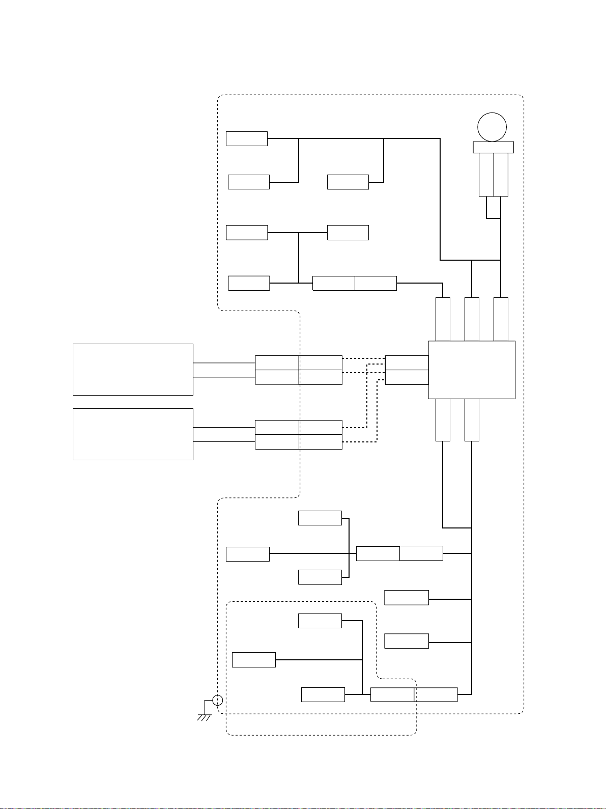
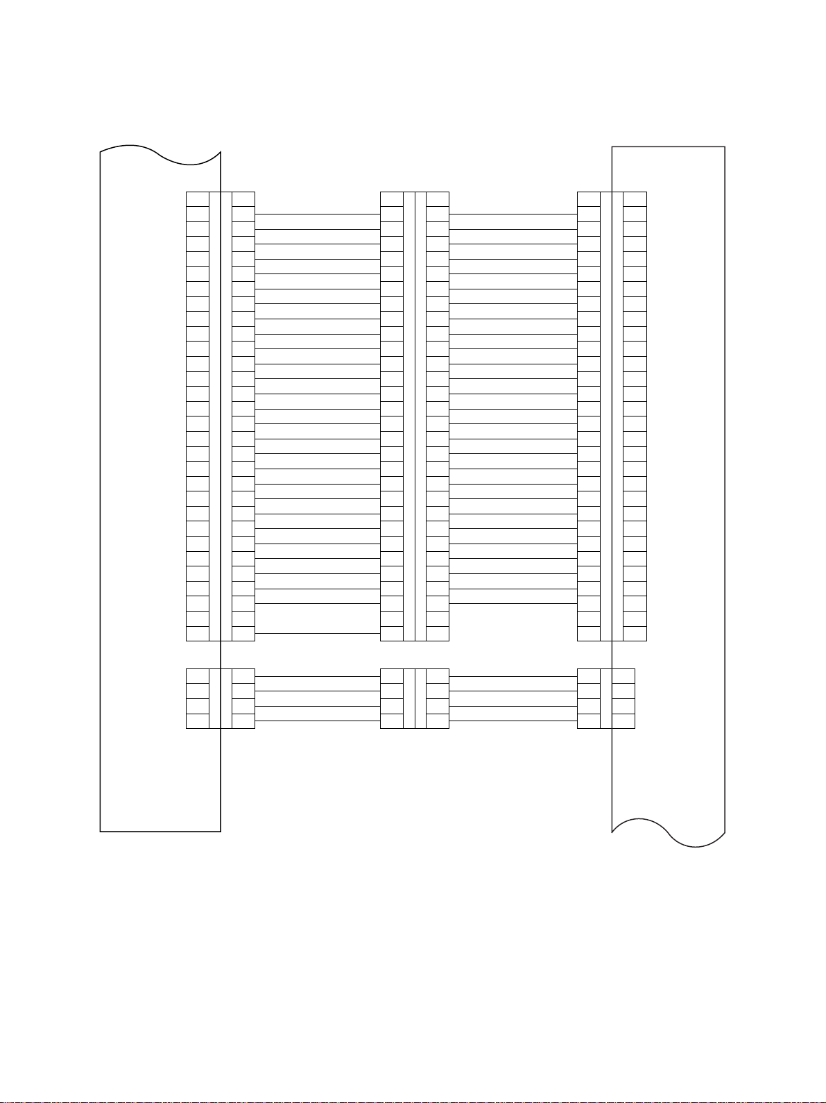
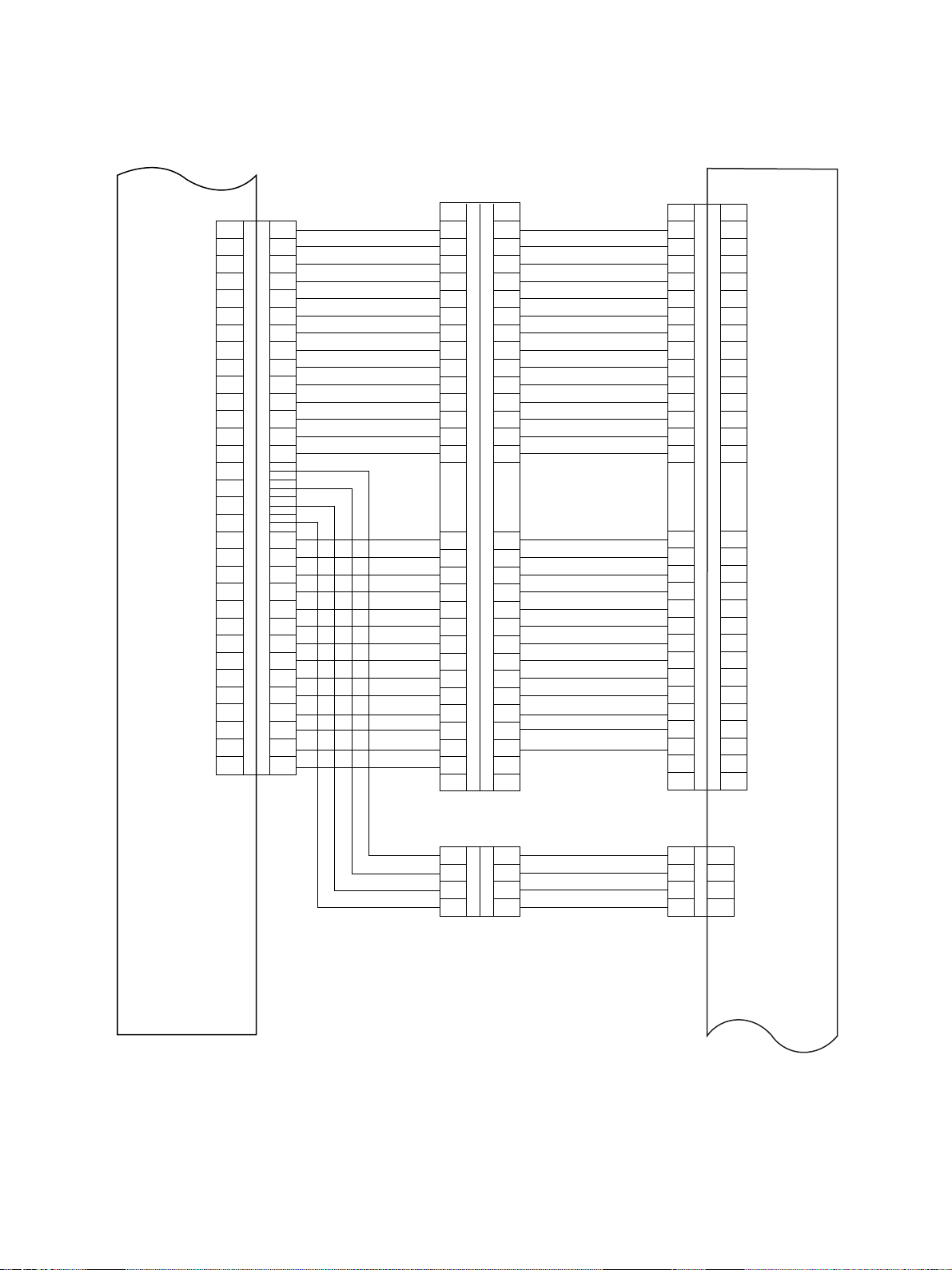
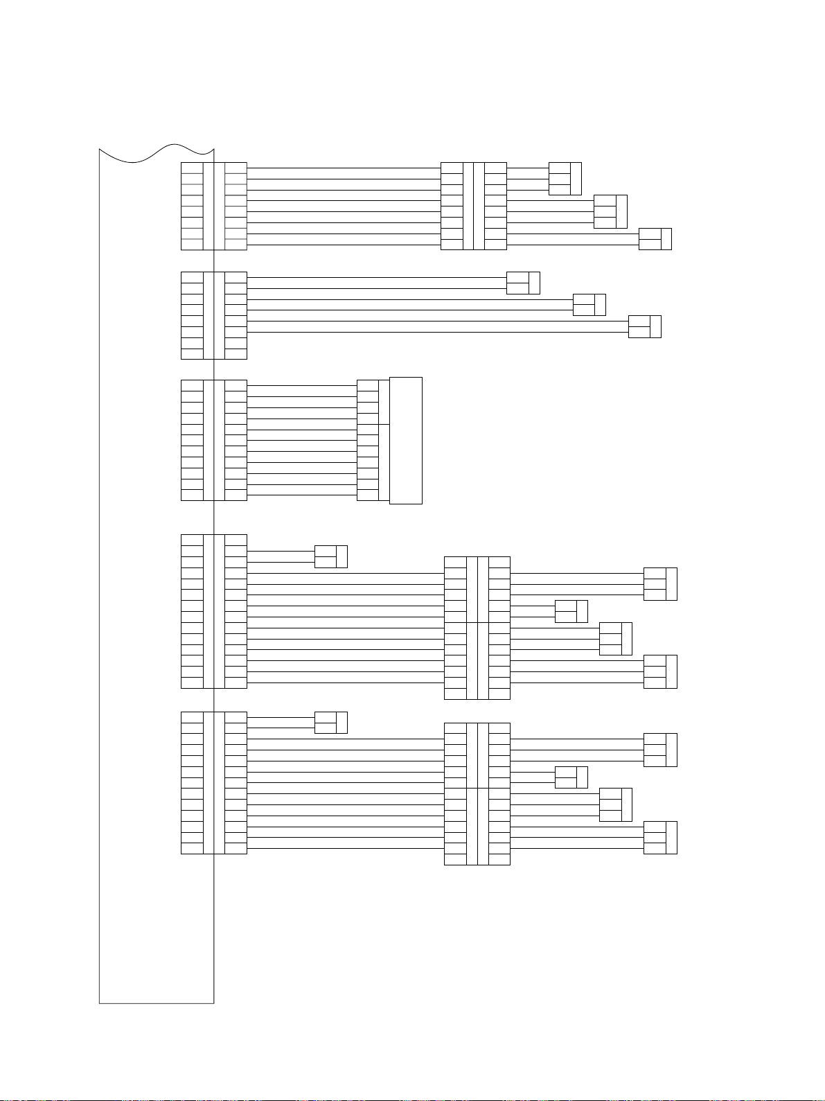
2.4 Harness Diagram
Copier
Copier
(PREMAGE165/255)
(DP1600/2500)
PFP
CN508
TR-CLT
CN507
T-UP-U-MTR
CN511
FED-U-SNR
CN510 CN520 CN520
FED-L-SNR
CN500
CN501
CN505
T-UP-L-MTR
CN509
SIDE-COV-SW
CN500
CN501
CN241
CN242
PFP-MTR
M
CN503
CN243CN247
CN244
PFP
PC board
CN502
CN246
Copier
Copier
(DP4500/3500)
(PREMAGE455/355)
CN318
FED-U-CLT
PFC
CN318
FED-L-CLT
CN567
CN568
TOP-U-SNR
CN567
CN568
CN314
CN316 CN516
ADPT
CN315
EMP-U-SNR
CN314
TOP-L-SNR
EMP-L-SNR
CN315 CN316 CN517
CN335
CST-U-SW
CN336
CST-L-SW
ADPT
CN248
October 2000 © TOSHIBA TEC 2 - 5 KD-1009 OVERVIEW
Page 11
A1
CLK-C
A2
CLK-B
A3
SCSW-C
PFPRST
SCSW-B
Copier (DP1600/2500)
LCFCNT
DRV7
DRV6
DRV5
DRV4
DRV3
DRV2
DRV1
DRV0
VDD
GND
SIZE-0
SIZE-1
SIZE-2
SIZE-3
RETS-0
RETS-1
RETS-2
RETS-3
RETS-4
RETS-5
RETS-6
RETS-7
A4
A5
A6
A7
A8
A9
A10
A11
A12
A13
A14
A15
B1
B2
B3
B4
B5
B6
B7
B8
B9
B10
B11
B12
B13
B14
B15
CN206
CN206
A1
A2
A3
A4
A5
A6
A7
A8
A9
A10
A11
A12
A13
A14
A15
B1
B2
B3
B4
B5
B6
B7
B8
B9
B10
B11
B12
B13
B14
B15
Copier (PREMAGE 165/255)
+24V
+24V
DG
DG
1
2
3
4
CN207
CN207
1
2
3
4
11
13
15
17
19
21
23
25
27
29
30
28
26
24
22
20
18
16
14
12
10
1
3
5
7
9
8
6
4
2
1
2
3
4
CN500
CN500
CN501
CN501
11
13
15
17
19
21
23
25
27
29
30
28
26
24
22
20
18
16
14
12
10
1
3
5
7
9
8
6
4
2
+24V
1
+24V
2
GND
3
GND
4
A1
A2
A3
A4
A5
A6
A7
A8
A9
A10
A11
A12
A13
A14
A15
B1
B2
B3
B4
B5
B6
B7
B8
B9
B10
B11
B12
B13
B14
B15
1
2
3
4
CN241
CN242
A1
A2
A3
A4
A5
A6
A7
A8
A9
A10
A11
A12
A13
A14
A15
CN241
B1
B2
B3
B4
B5
B6
B7
B8
B9
B10
B11
B12
B13
B14
B15
+24V
1
+24V
2
DG
3
DG
4
PFPCNT
CLK-C
CLK-B
SCSW-C
DRV7
DRV6
DRV5
DRV4
DRV3
DRV2
DRV1
DRV0
PFPRST
VDD
GND
SIZE-0
SIZE-1
SIZE-2
SIZE-3
RETS-0
RETS-1
RETS-2
RETS-3
RETS-4
RETS-5
RETS-6
RETS-7
SCSW-B
PFP
PC board
KD-1009 OVERVIEW 2 - 6 October 2000 © TOSHIBA TEC
Page 12
CLK-C
A1
CLK-B
A2
SCSW-C
PFPRST
Copier (DP4500/3500)
SCSW-B
Copier (PREMAGE 455/355)
DRV7
DRV6
DRV5
DRV4
DRV3
DRV2
DRV1
DRV0
VDD
GND
+24V
+24V
DG
DG
SIZE-0
SIZE-1
SIZE-2
RETS-0
RETS-2
RETS-3
RETS-4
RETS-5
RETS-7
RETS-5
RETS-6
RETS-7
LCCNT
A3
A4
A5
A6
A7
A8
A9
A10
A11
A12
A13
A14
A15
A16
B1
B2
B3
B4
B5
B6
B7
B8
B9
B10
B11
B12
B13
B14
B15
B16 B16
CN312
CN312
A1
A2
A3
A4
A5
A6
A7
A8
A9
A10
A11
A12
A13
A14
B3
B4
B5
B6
B7
B8
B9
B10
B11
B12
B13
B14
B15
11
13
15
17
19
21
23
25
27
29
30
28
26
24
22
20
18
16
14
12
10
1
3
5
7
9
8
6
4
2
CN567
CN567
11
13
15
17
19
21
23
25
27
29
30
28
26
24
22
20
18
16
14
12
10
PFPCNT
CN241
A1
A2
A3
A4
A5
A6
A7
A8
A9
A10
A11
A12
A13
A14
A15
CN241
B1
B2
B3
B4
B5
B6
B7
B8
B9
B10
B11
B12
B13
B14
B15
CLK-C
CLK-B
SCSW-C
DRV7
DRV6
DRV5
DRV4
DRV3
DRV2
DRV1
DRV0
PFPRST
VDD
GND
SIZE-0
SIZE-1
SIZE-2
RETS-0
RETS-2
RETS-3
RETS-4
RETS-5
RETS-7
RETS-5
RETS-6
RETS-7
SCSW-B
1
3
5
7
9
8
6
4
2
A1
A2
A3
A4
A5
A6
A7
A8
A9
A10
A11
A12
A13
A14
A15
B1
B2
B3
B4
B5
B6
B7
B8
B9
B10
B11
B12
B13
B14
B15
1
2
3
4
CN568
CN568
+24V
1
+24V
2
GND
3
GND
4
1
2
3
4
1
CN242
2
3
4
+24V
+24V
DG
DG
PFP
PC board
October 2000 © TOSHIBA TEC 2 - 7 KD-1009 OVERVIEW
Page 13
GND
FEDU
VDD
GND
FEDL
VDD
GND
COV-SW
1
2
3
4
5
6
7
8
CN243
CN243
1
2
3
4
5
6
7
8
8
7
6
5
4
3
2
1
CN520
1
2
3
4
5
CN520
6
7
8
GND
FEDU
VDD
GND
FEDL
VDD
GND
COV-SW
CN511
3
2 FED-U-SNR
1
CN510
3
2 FED-L-SNR
1
2
1
CN509
SIDE-COV-SW
CN244
CN244
CN246
CN246
CN247
CN247
CN248
CN248
1
2
3
4
5
6
7
8
1
2
3
4
5
6
7
8
14
GND
13
CST
12
11
10
9
8
7
6
5
4
3
2
1
GND
13
CST
12
11
10
9
8
7
6
5
4
3
2
1
TRMU-B
1
TRMU-A
2
TRMU-B
3
TRMU-A
4
+24V
5
FEDCLT
6
+24V
FEDCLT35
MOT-BRK
7
8
DG
1
DG
2
+24
3
+24
4
5
VDD
6
DIR
7
PLLOK
8
99
MOT-OFF
10 10
GND
11 11
14
13
GND
12
SIZCUO
11
VDD
10
PHU1
9
GND
8
+24V
7
PCLTU
VDD
6
TUPU
5
GND
4
VDD
3
PEMPU
2
GND
1
PFP PC Board
GND
13
12
SIZCUO
VDD
11
PUL1
10
GND
9
8
+24V
7
PCLTU
VDD
6
TUPU
5
GND
4
VDD
3
PEMPU
2
GND
1
1
2
1
2
CN335
CST-U-SW
CN336
CST-L-SW
4
3
2
1
7
6
5
4
3
2
1
CN502 CN503
PFP-MTR
(6)
1
CN516B
2
3
CN316B
4
5
1
2
CN516A
3
4
5
CN316A
6
(7)
(6)
1
CN517B
2
3
CN316B
4
5
1
2
CN517A
3
4
5
CN316A
6
(7)
(1)
(1)
(1)
(1)
CN505
1
T-UP-L-MTR
2
VCC
6
PHU1
5
GND
4
+24V
3
PCLTU
2
VCC
7
LPSON
6
GND
5
VCC
4
PESON
3
GND
2
VCC
6
PHU1
5
GND
4
+24V
3
PCLTU
2
VCC
7
LPSON
6
GND
5
VCC
4
PESON
3
GND
2
1
2
1
2
CN507
1
T-UP-U-MTR
2
CN318
FED-U-CLT
1
2 TOP-U-SNR
3
CN318
FED-L-CLT
1
2 TOP-L-SNR
3
CN508
1
2
1
2
3
CN314
1
2
3
1
2
3
CN314
1
2 EMP-L-SNR
3
TR-CLT
CN344
*PST-U-SNR
CN315
CN344
*PST-L-SNR
CN315
* for the DP4500/3500 only
KD-1009 OVERVIEW 2 - 8 October 2000 © TOSHIBA TEC
Page 14

2.5 Circuit Diagram
October 2000 © TOSHIBA TEC 2 - 9 KD-1009 OVERVIEW
Page 15

KD-1009 OVERVIEW 2 - 10 October 2000 © TOSHIBA TEC
Page 16

October 2000 © TOSHIBA TEC 2 - 11 KD-1009 OVERVIEW
Page 17

2.6 Assembly of PC Board
CN243 CN242
18
711
M3
CN244
18
11
14
C3
10/50
R1
IC1
8428KS
C4
10/50
IC4
8428KS
IC3
CN246
IC6
62308FT
1
IC7
MC74HC273AFL
CN247
C1
47/50
10K
MC74HC273AFL
PD
RV
CN241
A1
B15
CN248
M3
1114
HC244FL
HC244FL
HC244FL
A1
B1
C2
100/25
IC2
IC5
IC8
M3
5161
CN249 CN250
13
KD-1009 OVERVIEW 2 - 12 October 2000 © TOSHIBA TEC
Page 18

2.7 Timing Chart
(1 ) DP1600 (A4 sized sheet fed from the upper cassette)
ON
CW
CCW
CCW
MAIN-MTR
PFP-MTR
October 2000 © TOSHIBA TEC 2 - 13 KD-1009 OVERVIEW
OFFONOFFONOFFONOFF
OFF
TR-CLT
FED-U-CLT
FED-U-SNR
PFU-FED-CLT
ON
CW
ON
OFF
PFU-FED-SNR
RGST-SNR
ON
RGST-CL T
OFF
ON
OFF
EXIT-SNR
Page 19

(2 ) DP2500 (A4 sized sheet fed from the upper cassette)
CW
CW
CCW
CCW
MAIN-MTR
PFP-MTR
ON
ON
OFF
OFFONOFFONOFFONOFF
TR-CLT
FED-U-CLT
FED-U-SNR
PFU-FED-CLT
ON
OFF
PFU-FED-SNR
RGST-SNR
ON
OFF
RGST-CL T
ON
OFF
EXIT-SNR
KD-1009 OVERVIEW 2 - 14 October 2000 © TOSHIBA TEC
Page 20

(3 ) DP4500/3500 (A4 sized sheet fed from the upper cassette)
CCW
CW
CW
MAIN-MTR
ON
OFF
CCW
PFP-MTR
FED-U-CLT
ON
OFFONOFFONOFFONOFF
TR-CLT
FED-U-SNR
PFU-FED-CLT
ON
ON
OFF
PFU-FED-SNR
RGST-SNR
OFF
RGST-CL T
ON
EXIT-SNR
OFF
October 2000 © TOSHIBA TEC 2 - 15 KD-1009 OVERVIEW
Page 21

Page 22

3. GENERAL OPERATION
3.1 Description of Operations
[A] From power ON to standby
(1) When the copier is turned ON, power is also supplied to the feeder unit. Tray-up motor (M2)/(M3) is
turned ON to raise tray. Tray-up sensor (S4)/(S5) is turned ON correspondingly , then the tra y-up motor
(M2)/(M3) is turned OFF to stop the tray. If the empty sensor (S6)/(S7) is OFF (H) at this time, it is
judged that there is no paper in the cassette. If the empty sensor is ON (L), it is assumed that there is
paper in the cassette, and the tray stay in the raised position until the cassette is pulled out.
(2 ) If the power is turned ON when the cassette has been removed, the tray-up motor for that cassette is
not turned ON. The tray is r aised as soon as the cassette is installed, and it detects if there is paper
in the cassette.
(3 ) If either of the feed sensors (S2), (S3) is ON (there is paper in the transportation path) when the power
is turned ON, that means paper jam has occurred and operation is disabled until the paper is removed.
[B] Standby status
(1 ) T ra ys detect the paper as described abov e, and the copier goes into standb y status .
(2) The tray goes down automatically when the cassette is removed and it is raised as soon as the
cassette is installed again and checks if there is paper in the cassette.
[C] From the start to the end of copying
(1 ) The main motor of the copier is turned ON when the START key is pressed. About 0.1 sec. later , the
PFP motor (M1) and the transport clutch (C1) are turned ON to drive the transport rollers.
(2 ) When the copier judges that PFP is ready for feeding paper , it turns ON the feed clutch (C2)/(C3) of the
selected cassette. This clutch drives the pickup roller and feed roller to feed paper from the tr ay.
(3 ) The leading edge of the paper turns the feed sensor (S2)/(S3) ON. These are located right ne xt to the
exit side of the selected cassette. The feed clutch (C2)/(C3) is turned OFF and feeding from the
cassette is completed.
(4 ) The paper is transported to the copier by the PFP transport roller. If the trailing edge of the pre viously
sent sheet still remains at the feed sensor when the leading edge of the paper reaches the feed sensor
(S2)/(S3), the transport clutch (C1) is turned OFF to stop the transport of the paper. (In case of DP4500/
3500, the transport cluch (C1) is not turned OFF until the registration operation is completed regardless
of the size of the paper .)
(5 ) The trailing edge of the paper turns the feed sensor (S2)/(S3) OFF. These are located right next to the
exit side of the selected cassette. PFP then becomes ready for feeding the next sheet of paper, and
the procedures (2) to (4) are repeated.
(6 ) When the copying operation is completed, the main motor , PFP motor (M1) and transport clutch (C1)
are turned OFF and the transport roller is stopped.
October 2000 © TOSHIBA TEC 3 - 1 KD-1009 GENERAL OPERATION
Page 23

3.2 Error Detection
[A] Jam detection
(1) Paper jams (E15), (E16) and (E32, E34, E35) [DP4500/3500: (E15, E16) (E30~E36)] occurs in the
following cases.
a. Feed sensor (S2)/(S3) is not turned ON within 0.4 second after the feeding is started.
b . The leading edge of the paper does not pass the feed sensor (S2)/(S3) in the transport path within
a fixed time.
(2 ) Open the side cover of the paper feeder and remo ve all the paper remaining on the transport path and
close the side cover to clear the jammed paper . If either of the feed sensors (S2)/(S3) is still ON when
the side cover is closed, it is determined that there is still paper on the transport path and the paper jam
status is not canceled.
(3 ) When a paper jam occurs in the paper feeder during multiple copying, the sheet that was fed before the
jam is copied normally .
[B] Call Service
(1 ) The tray is raised when the power is turned ON or the cassette is inserted or removed.
If the tray-up sensor (S4)/(S5) is not turned ON within 8 (DP4500/3500: 12 seconds) seconds after the
tray has started to raise, a message to the effect that the selected cassette of that level cannot be
used is displayed in the control panel.
(2) The state (1) are cleared by removing the cassette. (This state cannot be cleared by opening and
closing the side cover)
KD-1009 GENERAL OPERATION 3 - 2 October 2000 © TOSHIBA TEC
Page 24

3.3 Flow Chart
(1) DP1600/2500
START key ON
Main motor ON
PFP motor ON
Polygonal motor ON
Developer bias ON
Separation charger ON
Main charger ON
Discharge lamp ON
Processing control
Polygonal motor
rotating normally?
YES
Call for Service
Laser ON
Transfer charger ON
Transfer guide bias ON
Laser OFF
Transfer charger OFF
Transfer-guide bias OFF
NO
"CA1"
Transpor t system control
Main motor
rotating normally?
YES
Call for Service
"C01"
PFP motor
rotating normally?
YES
Call for Service
"C04"
Upper cassette feed clutch ON
PFP
Upper feed
sensor ON?
Scanner system control
Carriages move backward
NO
Black shading
Exposure lamp ON
NO
Carriages Stopped
Carriages move forward
White shading
NO
Scanning
NO
H-Sync OK?
YES
Copier’s
Lower feed
sensor ON?
YES
NO
Call for
Service
"CA2"
YES
Remaining number
of copies=0?
YES
Registration
sensor ON?
YES
Polygonal motor OFF
Processing con-
trol completed
October 2000 © TOSHIBA TEC 3 - 3 KD-1009 GENERAL OPERATION
B
Paper jam
"E15"
NO
Paper jam
"E34"
NO
Paper jam
"E32"
Carriages stopped
Exposure lamp OFF
Carriages move backward
Carriages stopped
Scanner system
control completed
Page 25

B
Upper cassette feed clutch OFF
Registration clutch ON
Counters ON
Registration clutch OFF
NO
Remaining number
of copies = 0?
sensor 1
ON?
Exit
sensor 2
ON?
Main charger OFF
Main motor OFF
PFP motor OFF
Developer bias OFF
Separation charger OFF
Discharge lamp OFF
Exit
YES
YES
YES
NO
NO
Paper jam
"E01"
Paper jam
"E02"
Standby
KD-1009 GENERAL OPERATION 3 - 4 October 2000 © TOSHIBA TEC
Page 26

(2) DP4500/3500
START key ON
Main motor ON
PFP motor ON
Polygonal motor ON
Developer bias ON
Separation charger ON
Main charger ON
Discharge lamp ON
Processing control
Polygonal motor
rotating normally?
YES
Call for Service
Laser ON
Transfer charger ON
Transfer guide bias ON
Laser OFF
Transfer charger OFF
Transfer-guide bias OFF
NO
"CA1"
Transpor t system control
Main motor
rotating normally?
YES
Call for Service
"C01"
PFP motor
rotating normally?
YES
Call for Service
Upper cassette feed clutch ON
PFP transport clutch ON
PFP
Upper feed
sensor ON?
NO
NO
"C04"
NO
Scanner system control
Carriages move backward
Black shading
Exposure lamp ON
Carriages Stopped
Carriages move forward
White shading
Scanning
NO
H-Sync OK?
Call for
Service
YES
Upper cassette feed clutch OFF
YES
Copier’s transport clutch ON
Paper jam
"E15"
Carriages stopped
Exposure lamp OFF
"CA2"
NO
Remaining number
of copies=0?
Copier’s lower
NO
Carriages move backward
feed sensor ON?
YES
Polygonal motor OFF
YES
Paper jam
"E32"
Processing con-
trol completed
October 2000 © TOSHIBA TEC 3 - 5 KD-1009 GENERAL OPERATION
B
Carriages stopped
Scanner system
control completed
Page 27

B
Copier’s upper feed
sensor ON?
YES
Paper jam
Copier’s registration
sensor ON?
YES
Paper jam
PFP transport clutch OFF
Copier’s transport clutch OFF
Copier’s registration clutch ON
Copier’s transport clutch ON (up)
Counter ON
Copier’s registration clutch OFF
NO
"E31"
NO
"E30"
NO
Remaining number
of copies = 0?
sensor 1
ON?
Exit
sensor 2
ON?
Main charger OFF
Main motor OFF
PFP motor OFF
Developer bias OFF
Separation charger OFF
Discharge lamp OFF
Exit
YES
YES
YES
NO
NO
Paper jam
"E01"
Paper jam
"E02"
Standby
KD-1009 GENERAL OPERATION 3 - 6 October 2000 © TOSHIBA TEC
Page 28

4. DRIVE SYSTEM AND FEEDING OPERATION
4.1 Configuration and Drive System
The Paper F eed Pedestal (PFP) mainly consists of the cassette , pickup roller , feed roller , separation roller ,
transport roller and drive systems for these components.
• Feeding/Transport system
The PFP motor drives the pickup roller , feed roller , separation roller and tr ansport roller which are located
in the feeding area.
• Cassette tray system
This system raises and lowers the trays.
Upper/Lower cassette pickup roller
Upper/Lower cassette feed roller
Upper transport roller
Lower transport roller
Upper/Lower cassette
tray-up motor
Upper cassette
feed clutch
PFP motor
Transpor t clutch
Lower cassette feed clutch
October 2000 © TOSHIBA TEC 4 - 1 KD-1009 DRIVE SYSTEM
Page 29

Page 30

5. DISASSEMBLY AND RE-
PLACEMENT
5.1 Installation and Removal of Cas-
settes and Covers
[A] Cassettes
(1) Pull out the cassette fully and remove it while
lifting it up.
[B] Slot cover
(1 ) Pull out the upper cassette.
(2) Remove 2 screws and take off the slot co ver.
[C] Rear cover
(1) Remove the 5 screws fixing the rear cov er.
(2 ) Remove the rear cover while lifting it up.
[D ] Feeding-side front cover and Feeding-side
rear cover
(1 ) Remove 2 screws and take off the feeding-side
front cover.
(2 ) Remove 2 screws and take off the feeding-side
rear cover .
Slot cover
Rear cover
Feeding-side front cover Feeding-side rear cover
October 2000 © TOSHIBA TEC 5 - 1 KD-1009 DISASSEMBLY
Page 31

[E] Side cover
(1) Open the side cover. Loosen the belt and re-
move it.
(2 ) Disconnect one connector.
(3) Remove the side cover.
Connector
Belt
5.2 PC Board
(1 ) Remove the rear cov er .
(2 ) Disconnect 7 connectors and detach 4 lock sup-
ports to remove the PC board.
5.3 Upper and Lower T ransport Rollers
(Plastic Rollers)
(1) Remove the side cover and the feeding-side front
cover .
(When the upper transport roller is also removed,
take off the feeding-side front cover of the
copier.)
(2 ) Detach the springs and bushings from the front
and rear sides and take off the rollers.
Lock supports
Springs
Plastic rollers
Springs
KD-1009 DISASSEMBLY 5 - 2 October 2000 © TOSHIBA TEC
Page 32

5.4 Motors
[A] Tray-up motor unit
(1 ) Remove the rear cov er .
(2 ) Remove the harness from the 2 clamps.
(3 ) Disconnect 3 connectors.
(4) Remove 5 screws and take off the tray-up
motor unit.
Note: Tray-up motor unit is connected with the
copier with other harness. Do not disconnect
them and place the unit nearby the copier .
Connector
Tray-up
motor unit
Connector
Connector
Clamps
[B] PFP motor unit
(1 ) Disconnect 2 connectors.
(2) Remove 2 screws and take off the PFP motor.
(3 ) Remove one screw and take off the lever shaft
bracket.
(4) Remove 4 screws and take off the PFP motor
unit bracket.
Note: The positions to attach the
shift lever bracket and lever
DP4500/3500
(Lever position: HIGH)
shaft bracket differ according
to each model.
Lever shaft
bracket
(4) (4)
(3)
(2)
(4)
(4)
DP1600/2500
(Lever position: LOW)
Connectors
(5 ) Remove the clip and pull out the lever shaft.
(6) T ak e off the shift lever br acket. Remove the gears
and belt from the PFP motor unit bracket.
Gears
October 2000 © TOSHIBA TEC 5 - 3 KD-1009 DISASSEMBLY
Shift lever blacket
Clip
Gear
Belt
Lever shaft
Page 33

5.5 Feed/Separation/Pickup Rollers
[A] Feed unit
(1) Pull out the cassette.
(2) Remove one screw and take out the feed unit
toward the front side.
[B] Feed clutch
(1 ) Disconnect one connector.
(2) Remove 2 screws and take off the clutch bracket.
(3 ) Loosen one setscrew.
(4 ) Remove the feed clutch.
Feed unit
Clutch bracket
Connector
[C] Separation roller
(1 ) Remove one screw and take off the separation
roller holder.
(2) Remove the lever from the holder and take off
the separation roller along with its shaft.
(3) Remove the cover , arbor, clutch spring, and then
the separation roller from the shaft.
Separation roller
KD-1009 DISASSEMBLY 5 - 4 October 2000 © TOSHIBA TEC
Page 34

Note:
When reassembling the pickup roller , feed roler and
separation roller, pa y attention to the f ollowings:
1. Put a pin into the pulley.
2. Set the timing belt securely on the pulleys.
3. The “lock” direction of each one-way clutch is
different.
CLUTCH-6-L
CLUTCH-6-R
L
O
C
K
LOCK
LOCK
4. Fit the clips securely into the groove on the shaft.
5. Confirm that there is no oil staining etc. on the
surface of the timing belt, pulleys and rollers.
6. Pay attention to the mounting direction of the
Holder
Arbor
Lever
Cover
Clutch spring
Separation roller
Shaft
Spring
Arbor
Spring
rollers.
[D] Pickup roller
(1) Remove the pickup roller from the pickup arm
and take off the belt.
Paper
Pickup arm
Paper feed roller
Separation roller
One-way clutch
Pickup
roller
Pickup roller
Belt
Pickup arm
October 2000 © TOSHIBA TEC 5 - 5 KD-1009 DISASSEMBLY
Page 35

[E] Feed roller
(1) Remove the clip and take off the feed roller in
the direction of the arrow .
Clip
One-way clutch
Feed roller
5.6 Switches and Sensors
[A] Side cover open/close sensor
(1) Remove the side cove r .
(2) Release the latches and remove the sensor
cover.
(3 ) Disconnect one connector.
(4 ) Release the latches and remove the sensor .
[B] Upper/lower feed sensors
(1) Relase the latches and remove the sensor cov er.
(2 ) Disconnect one connector.
(3 ) Release the latches and remove the sensor .
Note: Upper and lower switches can be removed
with the same procedure.
Sensor cover
Latches
Side cover open/
close sensor
Latches
Sensor cover
Latches
Feed sensor
[C] Upper/lower cassette detection switches
(1) Pull out the cassette.
(2 ) Remove the rear cov er .
(3) Take off the tray-up motor unit and PFP motor
Connectors
unit.
(4) Disconnect the connectors connected to the cas-
sette detection switch.
(5 ) Release the latches and remove the switch from
the front side.
KD-1009 DISASSEMBLY 5 - 6 October 2000 © TOSHIBA TEC
Page 36

[D] Tray-up sensor and Paper empty sensor
(1) Disconnect the connector and release the latches
and remove the tr ay-up sensor .
(2) Disconnect the connector and release the latches
and remove the empty sensor .
[E] Paper stock sensor (for the DP4500/3500 only)
(1 ) Release the latches and remove the sensor .
(2 ) Disconnect one connector.
Tray-up sensor
Latch
Latch
Paper empty sensor
Paper stock sensor
October 2000 © TOSHIBA TEC 5 - 7 KD-1009 DISASSEMBLY
Page 37

Page 38

6. PERIODIC MAINTENANCE
Symbols used in the checklist
Cleaning Coating Replacing Date
A: Cleaning
with
alcohol
General Maintenance Checklist
Pickup roller(Upper/Lower) A 81
Feed roller(Upper/Lower) A 81
Separation roller(Upper/Lower) A AV 81 Note)
Drive gears(tooth face) W
*The above par ts are to be replaced depending on the number of the sheets of paper used in each
cassette.
Note: Apply the appropriate amount
of the grease as specified in the
right figure.
W: White grease (Molycoat)
A V: Alvania No. 2
Item to inspect Cleaning Coating Replace every Remarks
8 1 Every 81K copies
Replace if deformed or
damaged
1K copies
User’s name
Serial No
Inspector’s name
Remarks
Apply the grease on the
inside entirely
October 2000 © TOSHIBA TEC 6 - 1 KD-1009 PERIODIC MAINTENANCE
Page 39

MEMO
Page 40

MEMO
Page 41

MEMO
 Loading...