

Page 1
Instruction Manual
PROFESSIONAL SOUND SYSTEM
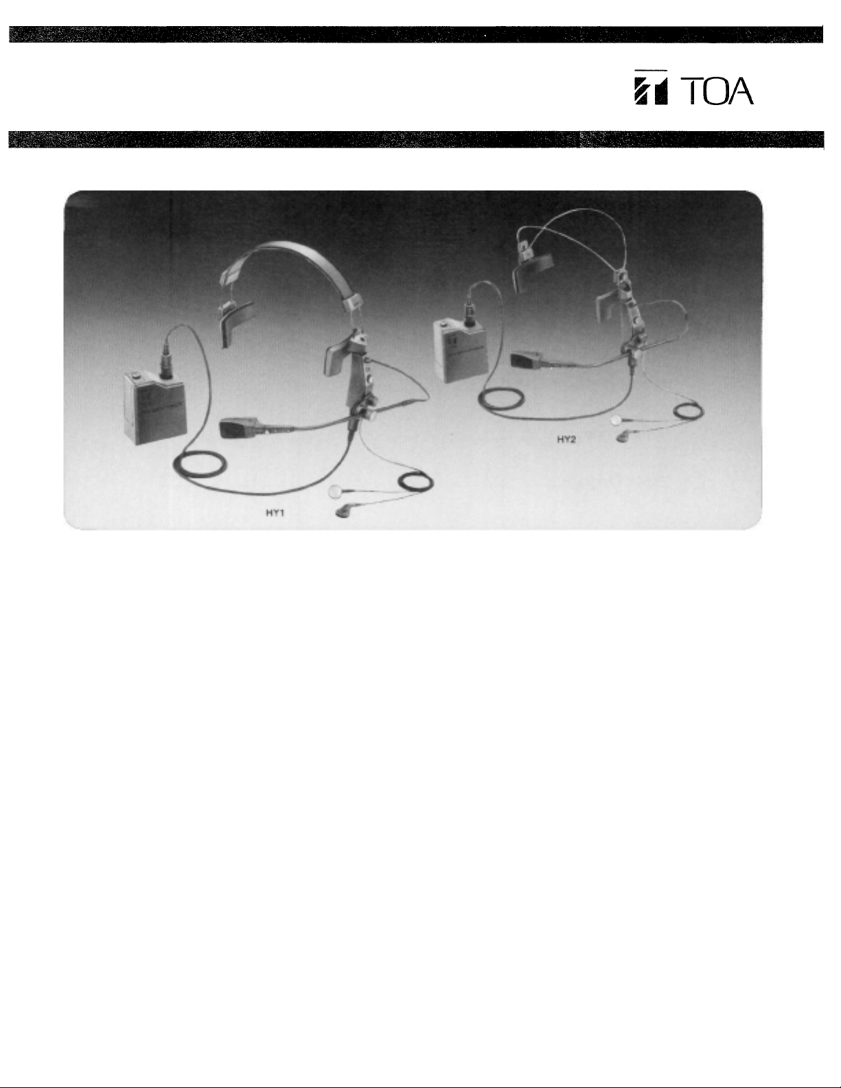
Headset Microphone Model HY1/HY2
GENERAL DESCRIPTION
The TOA HY 1 and HY 2 are headset type microphones
designed for professional level applications in recording, live
sound reinforcement, and broadcast environments. Unlike
the typical handheld or stand mounted mic, the "hands-free"
configuration allows the user to concentrate on the performance rather than the microphone. The HY's feature a unique design which provides superb performance and number
of functions never before available. They are ergonomically
designed to ensure comfort and stability for sustained
periods of time, without fatigue. The HY 1 and HY 2 are identical in design and function with the exception of the headband. The HY 1 headband is designed for extended wear, and
the HY 2 headband is designed to be hidden in the user's
hair.
The fixed-charge condenser mic element employs a backelectret type design with a gold-vaporized, extremely thin
membrane (4µm) to provide superior performance and high
stability. Frequency response is tailored to roll off the low
end, producing a well balanced low frequency characteristic
and eliminating problems associated with "proximity effect."
(Proximity effect causes the mic to accentuate the low frequencies, and in extreme cases may cause the vocal to
sound boomy and muffled.) A cardioid pickup pattern ensures
that surrounding noise is rejected, allowing the vocal to be
clear, clean and distinctive.
The HY headsets are equipped with an interchangeable mic
capsule which is voiced for male vocal response (HMV),
however, optional capsules are available. The HFV is voiced
for female or tenor male vocals, and the HCM for limited
bandwidth intercommunications. All mic capsules feature a
red LED to give a visual indication of "mic live" status. A
cough button is also provided on the headset to allow the
user to turn the mic element o ff when necessary (the LED
goes out).
The HY headsets are equipped with a sturdy beltpack which
provides operating power, mixing, and stereo monitoring
functions. The monitoring system is designed to allow the
user to independently control monitor (foldback) sends and
personal vocal level through the integral stereo headphone
system, directly from the beltpack. An optional 15 foot extension cable (C15-HY) allows the beltpack to be isolated from
the headset. The HY systems may be operated from two 1.5
volt "AA" batteries, or from an external phantom power
supply.
FEATURES
1. Ergonomic "hands-free" design provides secure attachment to user's head, and allows comfortable wear
without fatigue.
2. Smooth, extended "vocal" frequency response, and excellent transient response.
3. High quality, fixed-charge condenser microphone element
with cardioid pick-up pattern. Interchangeable mic capsules allow precision response tailoring for optimum
vocal performance.
4. Standard version is fitted with mic capsule designed for
male vocal response (HMV). Optional capsules are
available for female vocal, or male tenor vocal (HFV), and
limited bandwidth intercommunications (HCM).
5. Integral stereo headphone monitoring system for "personalized" foldback and cueing functions.
6. Red LED lights to indicate "mic live" status.
7. Cough button.
8. Headset may be worn from either right or left side.
9. System may be powered fro m two 1.5 volt "AA" batteries.
or an external phantom power supply.
10. Sturdy beltpack provides operating power, mixing and
monitoring functions.
Page 2

Contents
Assembly Diagram................................................................................................
Operating Instructions...........................................................................................
Stereo Headphone Monitoring System..............................................................
Capsule Replacement...........................................................................................
HY Applications Guide...........................................................................................
HY1/HY2 Specifications.................................................................................
Dimensions.......................................................................................................
Block Diagram........................................................................................................
2
3
4
5
5
6~7
7~8
8 — 1
—
Page 3
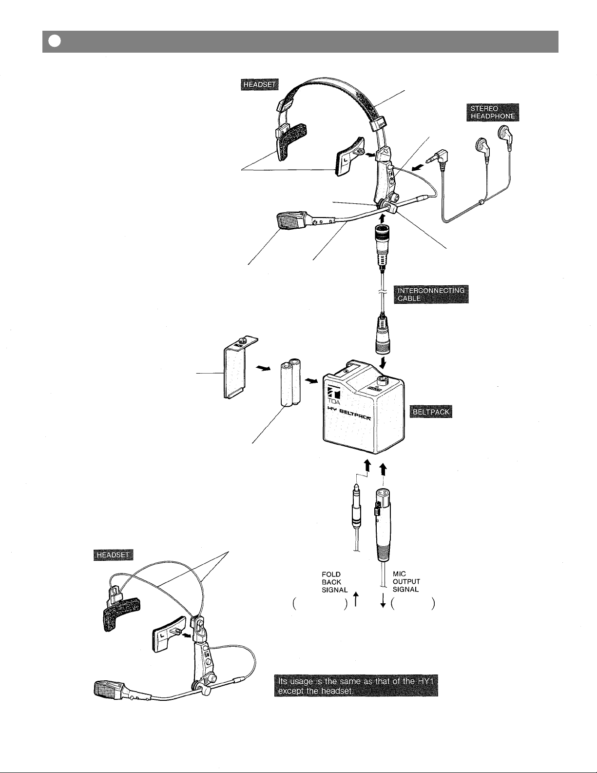
Assembly Diagram
HY1 (left-side operation)
HEAD
PAD
MIC
CAPSULE
"HMV"
MIC
ADJUSTMENT
KNOB
MIC ARM
HEAD
BAND
COUGH
BUTTON
AR M HOLDER
BATTERY
COVER
HY2 (left-side operation)
"AA" BATTERY×2
HEAD
BAND
FROM MIXING
CONSOLE
TO MIXING
CONSOLE
—2—
Page 4

Operating Instructions
<Assembly Instructions for left-side operation>
1. Assemble the HY headset according to the
assembly diagram.
(A) Attach the head pad marked "L" to the left side of
the headset, and the head pad marked "R" to the
right side, by pressing firmly until they "snap" into
place.
(B) Connect the interconnecting cable to the headset
and the beltpack, ensuring that the locking ring of
each connector is fully engaged.
(C) If the internal monitoring system is to be used,
connect the stereo mini plug of the PH 5 head-
phone to the headphone jack of the headset.
(Note: Other stereo headphones with an im-
pedance of 16 ohms or greater may be used if
desired.)
2. Insert the "L" and "R" units of the headphone into
the respective left and right ears as illustrated.
3. Set the cough button to the "mic off" position.
"mic
on"
position
"mic off"
position
6. Turn the beltpack power switch to "OFF," and
rotate the monitor level volume control to "MIN"
and the monitor balance control to its center postion. Connect an XLR cable between the MIC
OUTPUT of the beltpack, and a low-Z input of a
mixer or sound system. If the integral monitoring
system is to be used, insert a stereo or mono 1/4"
phone plug into the LINE INPUT JACK, and slide
the line mode selector switch to the appropriate
setting.
7. Place the beltpack power switch in the "ON" position. Set the COUGH BUTTON to the "ON" position, and the red LED will light to indicate "mic
live" status. Rotate the MONITOR LEVEL VOLUME
CONTROL to obtain a desirable level in the head-
phones, and adjust the MONITOR BALANCE CONTROL to obtain the proper "mix" between the direct
vocal and the line input monitor signal.
8. For right-side operation, reverse the positions of the
"L"and "R" head pads. The MIC ARM should be
reversed by carefully pulling the CANTILEVER out
away from the headset (just enough for clearance)
and swinging it to the other side; then gently lower
the arm to the surface of the headset. Orient the
red LED of the mic capsule toward the face, by
first loosening the MIC ADJUSTMENT KNOB, turn-
ing the shaft, and then retightening the knob.
4. Position the headset so the "L" and "R" head pads
rest immediately above the respective "L" and "R"
ears, and adjust the headband for a comfortable fit.
5. Loosen the mic adjustment knob, and position the
mic capsule approximately 10-25mm (1/2-1 inches)
from the corner of the mouth. Ensure that the cantilever is positioned fully downward, and carefully
tighten the mic adjustment knob to hold the mic
arm in the desired location. You should experiment
with the positioning of the mic capsule, in relation
to the mouth, to determine the location that provides the best reproduction of your individual vocal
tonality and performing style.
Note: The cantilever that connects the mic arm to
the body of the headset allows you to swing the
mic arm up and away from the face when
necessary, and then reposition the mic arm to exactly the same location when desired.
CANTILEVER
POSITION FOR
LEFT-SIDE
OPERATION
OFF
POSITION
SPECIAL
SCREW
POSITION FOR
RIGHT-SIDE
OPERATION
— 3 —
Page 5

Stereo Headphone Monitoring System
The stereo headphone monitoring system was designed to monitor the vocal, direct from the
mic capsule, and mix it with an external line level input signal, such as a monitor (foldback)
signal from a mixing console. The combined signals are sent to the stereo headset after being
amplified by the beltpack's stereo amplifier. This allows the user to adjust his own mixing
balance and master sound level independently of other performers. Disconnecting the headphone makes it possible to use the headset only as a microphone.
The monitoring system is powered by two 1.5 volt "AA" dry cell batteries, which are housed in
the beltpack. To operate the unit, turn the battery power switch to the "ON" position. Please
note that even though the HY headset is designed to operate from an external "Phantom"
power supply, the monitoring system, because of its relatively high power requirements, still
requires power from the batteries in the beltpack.
)
Control Panel Diagram
Line Mode
Selector Switch
Monitor Balance
Control
———
)
Battery
Power Switch
Line
Input Jack
Battery Power Switch and Phantom power supplies :
This switch turns the beltpack battery power supply
on or off. Setting the switch to ON supplies battery
power to the mic capsule as well as to the headphone monitoring system. If phantom power is supplied from an external source to the beltpack, the
mic capsule is automatically switched to the external source for its operation, regardless of the posi-
tion of the BATTERY POWER SWITCH.
NOTE:
The headphone monitoring system always requires
battery power from the beltpack, due to the
relatively high power requirements common to this
type of system.
Line Input Jack:
This jack accepts any line level input signal, and is
rated +4dB 10K-ohms. The jack would typically be
connected to either a stereo or mono send from a
mixing console. It also serves very well as an input
for a tape deck or other pre-recorded music
source, except a magnetic turntable. Set the LINE
MODE SELECTOR SWITCH to STEREO or MONO
according to the type of 1/4" phone plug which is
inserted into this jack.
Mic Output Connector:
The vocal signal from the headset microphone is
routed to this XLR connector. The signal available
at this output is not affected by the settings of
either the MONITOR BALANCE CONTROL or the
MONITOR LEVEL VOLUME CONTROL. The output
impedance is 250 ohms balanced, and would
typically be connected to a low impedance XLR
connector of a mixing console or powered sound
system.
Monitor Level
Volume Control
Mic
Output Connector
Line Mode Selector Switch :
The switch setting should be determined by the
type of 1/4" plug (stereo or mono) which is inserted
into the LINE INPUT jack. Place the switch in the
STEREO position when a stereo plug is inserted,
and to MONO when a mono plug is inserted. Set-
ting the switch to the MONO position when a
stereo signal is inserted will cause the "R" signal to
be disconnected from the circuitry, and only the
"L" signal will be heard through the headphones.
Please see the block diagram for a full understan-
ding of the signal flow path.
Monitor Balance Control:
This control adjusts the balance or "mix" heard
through the stereo headphone system, between the
direct vocal from the headset mic, and the line input signal. The volume of the direct vocal increases in relation to the level of the line input
signal as the control is rotated toward "MIC," and
decreases as the control is rotated toward "LINE."
Monitor Level Volume Control:
This control adjusts the volume level heard through
the stereo headphone system. It does not in any
way effect the output of the mic signal through the
MIC OUTPUT connector.
—4—
Page 6

Capsule Replacement
"HMV" capsule (accessory)
"HFV" capsule (option)
"HCM" capsule (option)
HY Applications Guide
LOCK SCREW
Loosen the lock screw, replace the mic capsule
carefully, and tighten the lock screw.
LIVE ON-STAGE
Monitor send out
HY
in
vocal mic out
out
(mono or stereo)
RECORDING STUDIO
Cue mix out
HY
in
vocal mic out
out
(stereo or mono)
HOME RECORDING
in
HY
out
STAGE CREW COMMUNICATIONS
Talkback out
HY
in
out
(single or dual channel)
com mic out
Mixing Console
low-Z input
Recording Console
balanced input
Porta-Studio
low-Z input
Mixing Console
cue input
BROADCAST PRODUCTION
Cue output
in
HY
out
VIDEO POST PRODUCTION
in
HY
out
(single or dual channel)
producer/director mic out
Cue output
(stereo or mono)
announcer mic out
COMMERCIAL
Talkback out
HY
in
out
(single or dual channel)
vocal mic out
INDUSTRIAL
Communications out
HY
in
out
(single or dual channel)
control mic out
Broadcast Console
cue input
Recording Console
balanced input
Communications
Control Center
balanced mic input
Voice Activated
(computer assisted)
Manufacturing
voice control input
LIVE BROADCAST
HY
in
out
(single or dual channel)
announcer mic out
Cue/monitor out
Broadcast Console
low-Z balanced
input
INSTITUTIONAL
HY
—5—
in
Director mic out
out
Cue/monitor out
(stereo or mono)
Mixing Console
cue input
Page 7

HY1/HY2 Specifications
<Construction>
Headset
Mic Capsule "HMV"
Beltpack
Interconnecting Cable
Stereo Headphone
<Microphone>
Mic capsule
Application
Type
Frequency response
Polar pattern
Impedance
Output levels (.1,000 Hz )
Open circuit voltage
(OdB = 1V/µbar)
Power level
(OdB=1mW/10µbars)
EIA rating Gm
(OdB = 1 mW/0.0002µbar)
Equivalent noise level
Maximum SPL
Phasing
Power supply
Current drain
Output connector
HMV capsule Frequency Response
HMV (accessory)
Male vocals
Fixed-charge (back-electret) condenser
70-20,000 Hz
Cardioid
250 ohms balanced
-77 dB
-57 dB
-149
dB
35 dB (A-weighted)
122dB(at 1,000 Hz 1%THD)
Positive pressure on diaphragm produces positive voltage at pin 2
Two 1 .5 volt "AA" batteries or 9 to 52 volts phantom power supply
(Phantom power supply has automatic priority over batteries)
0.8 mA (9V phantom)-5.3 mA (52V phantom)
XLRM type
HFV (option)
Female vocals or male
tenor vocals
60-20,000 Hz
-74 dB
-54 dB
-146
dB
HCM (option)
Communication
100-20,000 Hz
-77 dB
-57 dB
-149
dB
Polar Pattern
HFV capsule Frequency Response
HCM capsule Frequency Response
Polar Pattern
Polar Pattern
— 6 —
Page 8

HY1/HY2 Specifications
<Monitor amplifier>
Maximum output
55mW/ch (18 ohms load 10%THD)
Line input
+4 dB/10 kilo-ohms
("BALANCE": center "LEVEL": max 2mW output)
Frequency response
110-15,000 Hz (mic)
35-15,000 Hz (line input)
Power supply
Two 1.5 volt "AA" batteries
<Stereo headphones>
Driver unit
ø 15 mm (ø 0.59")
Frequency response
50-20,000 Hz
Impedance
18 ohms
Sensitivity
102dB/mW
<Battery life (alkaline batteries)>
12 hours (maximum monitor level)
60 hours (1mW monitor level)
80 hours (without monitoring)
Batteries should be replaced when the LED
indicator does not light brightly.
<Net weight>
headset: 105 grams (3.7 oz) /HY1
85 grams (3.0 oz) /HY2
Beltpack: 265 grams (9.3 oz) including batteries
HMV capsule: 15 grams (0.5 oz)
Interconnecting cable: 34 grams (1.2 oz)
Stereo headphone: 10 grams (0.4 oz) including cord
<Standard accessories>
Hard case
Special screwdriver
<Optional accessories>
HFV: Replacement capsule for female or tenor male
vocals
HCM: Replacement capsule for communication
C15-HY: Extension cable (15 ft)
C15-M: XLR to XLR cable (15 ft)
C20-M: XLR to XLR cable (20 ft)
Dimensions
HY1
— 7 —
Page 9

Dimensions
HY2 (same as that of the HY1 except the headset)
Block Diagram
LED
COUGH
BUTTON
MIC
UNIT
STEREO
HEADPHONE
PHANTOM
PRIORITY CIRCUIT
BATT
POWER
SW.
MIC
REGULATOR
LINE
BALANCE
OUTPUT
TRANSFORMER
LINE
SW.
PHANTOM
POWER
MONO
STEREO
MIC
OUTPUT
LINE
INPUT
LEVEL
—8—
Page 10

Printed in Japan
133-04-168-80
 Loading...