

Toshiba HWS-P805XWHM3-E, HWS-P805XWHT9-E, HWS-P1105XWHT9-E, HWS-P1105XWHT6-E, HWS-P1105XWHM3-E User Manual
...Page 1
AIR TO WATER HEAT PUMP
Installation Manual
Hydro Unit
Model name:
HWS-P805XWHM3-E
HWS-P805XWHT6-E
HWS-P805XWHT9-E
HWS-P1105XWHM3-E
HWS-P1105XWHT6-E
HWS-P1105XWHT9-E
English
Page 2

Hydro Unit Installation Manual
Please read this Installation Manual carefully before installing the Air to Water Heat Pump.
• This Manual describes the installation method of the hydro unit.
• For installation of the outdoor unit, follow the Installation Manual attached to the outdoor unit.
REFRIGERANT
This Air to Water Heat Pump uses an HFC refrigerant (R410A) in order to prevent destruction of the ozone
layer.
Contents
1 General information . . . . . . . . . . . . . . . . . . . . . . . . . . . . . . . . . . . . . . . . . . . . . . . . . . . 2
2 Accessory parts . . . . . . . . . . . . . . . . . . . . . . . . . . . . . . . . . . . . . . . . . . . . . . . . . . . . . . 3
3 Preparations for installation . . . . . . . . . . . . . . . . . . . . . . . . . . . . . . . . . . . . . . . . . . . . 4
4 Precautions for safety . . . . . . . . . . . . . . . . . . . . . . . . . . . . . . . . . . . . . . . . . . . . . . . . . 5
5 Example of Hydro Unit installation . . . . . . . . . . . . . . . . . . . . . . . . . . . . . . . . . . . . . . . 8
6 Main components of Hydro Unit . . . . . . . . . . . . . . . . . . . . . . . . . . . . . . . . . . . . . . . . 10
7 Hydro Unit installation . . . . . . . . . . . . . . . . . . . . . . . . . . . . . . . . . . . . . . . . . . . . . . . . 12
8 Group Control . . . . . . . . . . . . . . . . . . . . . . . . . . . . . . . . . . . . . . . . . . . . . . . . . . . . . . . 31
9 Start up and configuration . . . . . . . . . . . . . . . . . . . . . . . . . . . . . . . . . . . . . . . . . . . . . 32
10 Maintenance . . . . . . . . . . . . . . . . . . . . . . . . . . . . . . . . . . . . . . . . . . . . . . . . . . . . . . . . 55
11 Troubleshooting . . . . . . . . . . . . . . . . . . . . . . . . . . . . . . . . . . . . . . . . . . . . . . . . . . . . . 56
12 Technical parameters . . . . . . . . . . . . . . . . . . . . . . . . . . . . . . . . . . . . . . . . . . . . . . . . . 63
1-EN
–1–
Page 3
Hydro Unit Installation Manual
1
General information
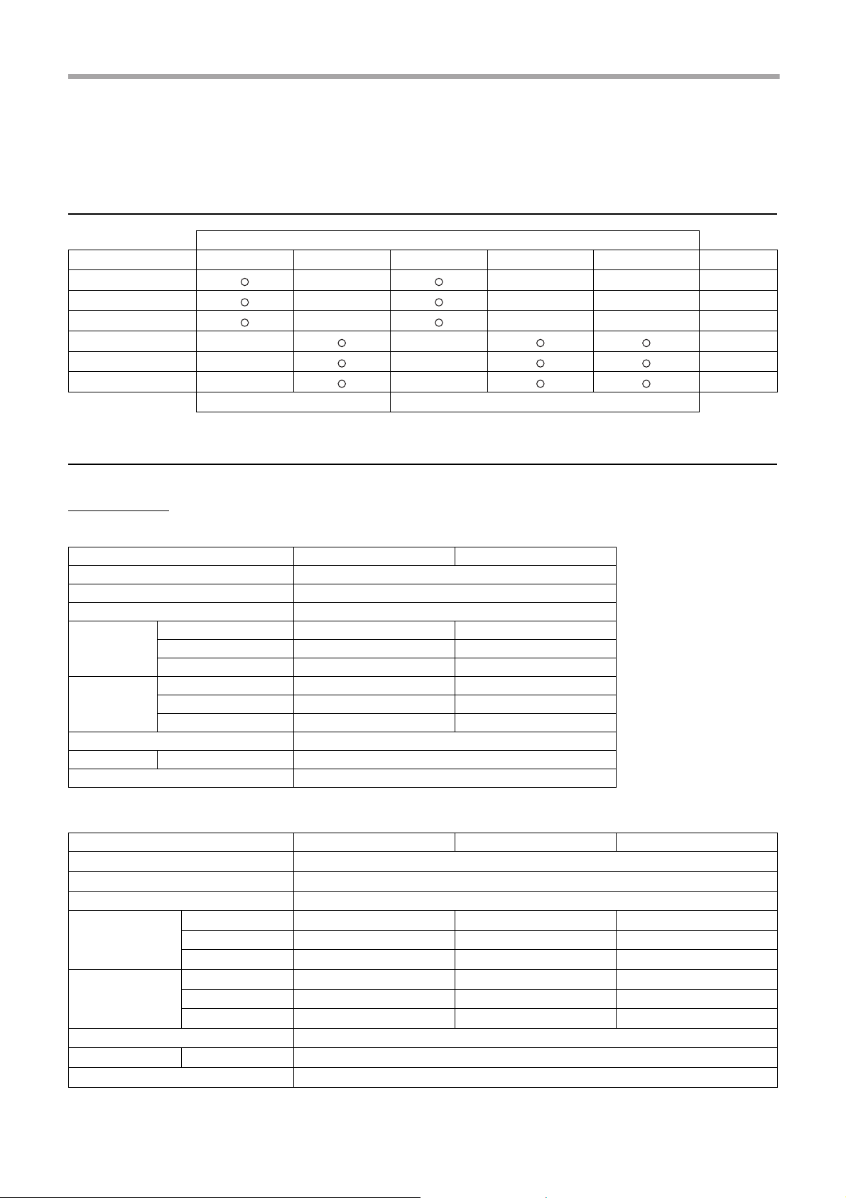
System combination
Outdoor Unit
Hydro Unit HWS-P805HR-E HWS-P1105HR-E HWS-P805H8R-E HWS-P1105H8R-E HWS-P1405H8R-E Backup heater
HWS-P805XWHM3-E - - - ~, 3kW
HWS-P805XWHT6-E - - - 3N~, 6kW
HWS-P805XWHT9-E - - - 3N~, 9kW
HWS-P1105XWHM3-E - - ~, 3kW
HWS-P1105XWHT6-E - - 3N~, 6kW
HWS-P1105XWHT9-E - - 3N~, 9kW
single phase model 3 phase model
General specifications
Outdoor Unit
Single Phase model
Outdoor unit HWS-P805HR-E HWS-P1105HR-E
Power supply 220-230 V ~ 50 Hz
Type INVERTER
Function Heating & Cooling
Capacity (kW) 8.0 11.2
Heating
Cooling
Refrigerant R410A
Dimension HxWxD (mm) 1,340x900x320
Cord heater (W) 75
Input (kW) 1.68 2.30
COP (W/W) 4.76 4.88
Capacity (kW) 6.0 10.0
Input (kW) 1.64 3.33
EER (W/W) 3.66 3.00
3 Phase model
Outdoor Unit HWS-P805H8R-E HWS-P1105H8R-E HWS-P1405H8R-E
Power supply 380-400V 3N~ 50Hz
Type INVERTER
Function Heating & Cooling
Capacity (kW) 8.0 11.2 14.0
Heating
Cooling
Refrigerant R410A
Dimension H×W×D (mm) 1,340×900×320
Cord heater (W) 75
Input (kW) 1.71 2.34 3.16
COP 4.684.804.44
Capacity (kW) 6.0 10.0 11.0
Input (kW) 1.64 3.33 3.90
EER 3.663.002.82
–2–
2-EN
Page 4
Hydro Unit Installation Manual
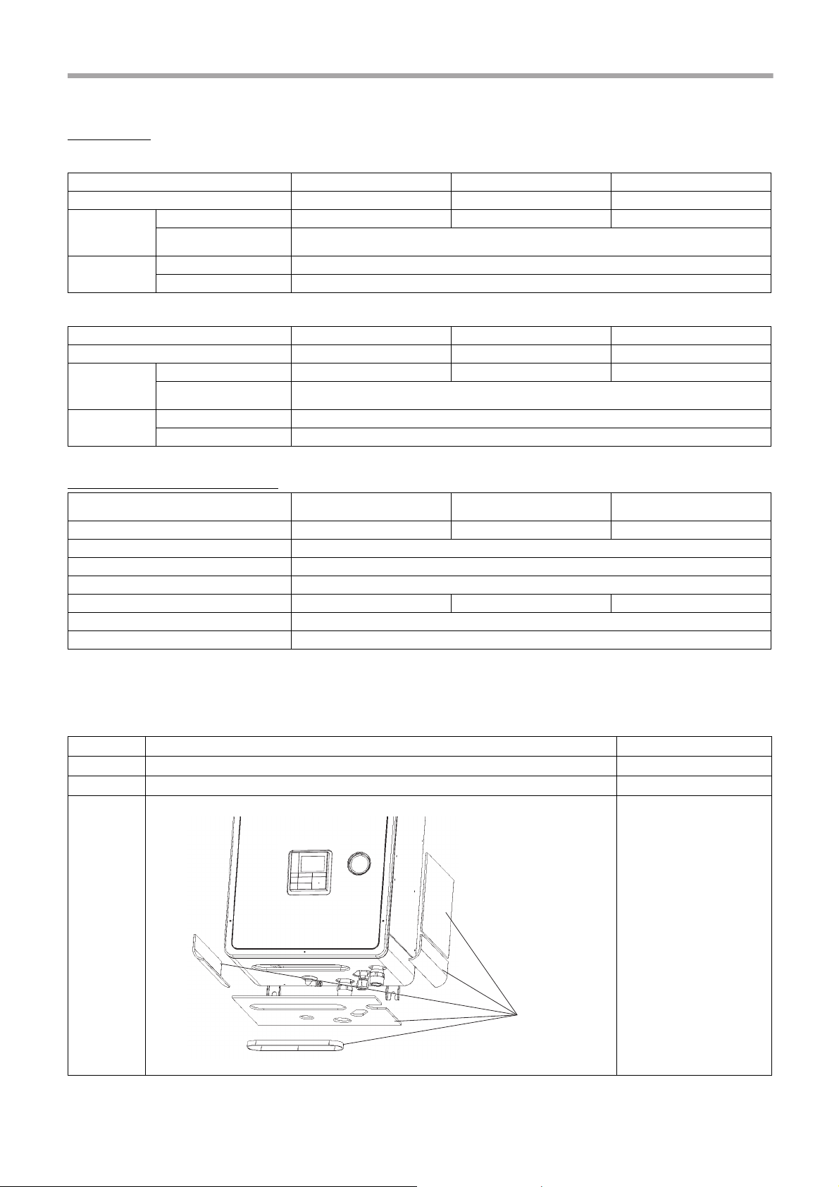
Insulator
Hydro Unit
8 kW model
Hydro Unit HWS-P805XWHM3-E HWS-P805XWHT6-E HWS-P805XWHT9-E
Back up heater capacity (kW) 3.0 6.0 9.0
for back up heater 220-230 V ~ 50 Hz 380-400 V 3N~ 50 Hz 380-400 V 3N~ 50 Hz
Power supply
Leaving water
temperature
for hot water cylinder heater
(option)
Heating (°C) 20-60
Cooling (°C) 7-25
220-230 V ~ 50 Hz
11 kW model
Hydro Unit HWS-P1105XWHM3-E HWS-P1105XWHT6-E HWS-P1105XWHT9-E
Back up heater capacity (kW) 3.0 6.0 9.0
Power supply
Leaving water
temperature
for back up heater 220-230 V ~ 50 Hz 380-400 V 3N~ 50 Hz 380-400 V 3N~ 50 Hz
for hot water cylinder heater
(option)
Heating (°C) 20-60
Cooling (°C) 7-25
220-230 V ~ 50 Hz
Hot Water Cylinder (option)
Hot water cylinder (option)
Water volume (liter) 150 210 300
Power supply 220-230 V ~ 50 Hz
Max water temperature (°C) 75
Electric heater (kW) 2.7
Height (mm) 1,090 1,474 2,040
Diameter (mm) 550
Material Stainless steel
2
Accessory parts
No. Parts name Quantity
1 Installation Manual (this document) 1
2 Owner’s Manual 1
Insulator for cooling
HWS-1501CSHM3-E
HWS-1501CSHM3-UK
HWS-2101CSHM3-E
HWS-2101CSHM3-UK
HWS-3001CSHM3-E
HWS-3001CSHM3-UK
3-EN
3
5
–3–
Page 5
Hydro Unit Installation Manual
3
Preparations for installation
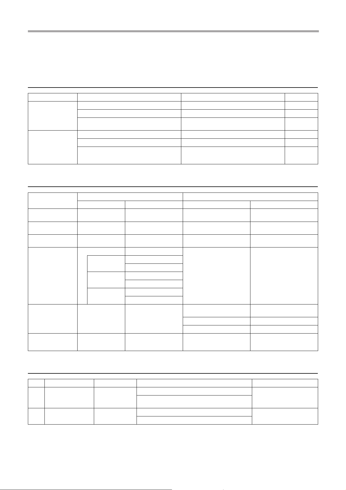
Parts required to connect this product (Common items)
Category Part Specification Quantity
Strainer (water filter) 1 1/4" 30 to 40 meshes 1
Water piping
Electrical system
Drain cock (for water charge) 1
Isolating ball valves
Earth leakage breaker for main power supply 30 mA 1
Earth leakage breaker for backup heater 30 mA 1
(Option)
Earth leakage breaker for hot water cylinder
heater
1 1/4"
for service 1 1/4"
30 mA 1
2
Options required for each function
Purpose
Heating – –
Heating &Cooling (all
rooms)
Heating & Cooling
(partly heating only)
Hot water supply
2-zone control – –
Interlocking with boiler
In the Hydro Unit Purchased part
Part name Model name Part name Prescribed specification
Radiator(s), Fan coil(s), Under
floor heating
– – Fan coil(s)
––
Hot water cylinder
150 L
210 L
300 L
Output control board
kit (1)
Motorized 2-way valve (for
cooling)
HWS-1501CSHM3-E
HWS-1501CSHM3-UK
HWS-2101CSHM3-E
HWS-2101CSHM3-UK
HWS-3001CSHM3-E
HWS-3001CSHM3-UK
TCB-PCIN3E Boiler
Motorized 3-way valve
Earth leakage breaker
Motorized mixing valve
Circulator pump Other power supply
Buffer tank
Refer to “Control parts
specifications” on page 21.
Refer to “Control parts
specifications” on page 21.
Refer to “Control parts
specifications” on page 21.
Other power supply.
Signal 12 V input function is
required for boiler.
Optional parts
No. Part name Model name Application Remarks
Boiler-linked output, Alarm output
1 External output board TCB-PCIN3E
2 External input board TCB-PCMO3E
Defrost signal output, compressor operation signal
output
Cooling/heating thermostat input
Emergency stop signal input.
Use specified products for the outdoor unit, Hydro Unit, and hot water cylinder.
Do not use commercially available products.
Use parts that conform to prescribed specifications for parts to be connected to the Hydro Unit.
If unspecified products or parts are used, a malfunction, failure or fire may be caused.
–4–
Up to two boards (according to
applications)
Up to two boards (according to
applications)
4-EN
Page 6

Hydro Unit Installation Manual
WARNING
4
Precautions for safety
General safety precautions
Ensure that all Local, National and International regulations are satisfied.
• Read the “Precautions for safety” carefully before installation.
• The precautions described below include the important items regarding safety – Observe
them without fail.
• After the installation work has been completed, perform a test run to check for any problems.
Follow the Owner’s Manual to explain how to use and maintain the unit to the customer.
• Turn off the main power supply switch (or breaker) before unit maintenance.
• Ask the customer to keep the Installation Manual along with the Owner’s Manual.
Refrigerant precautions
• If a refrigerant leak is suspected contact the dealer who supplied the system, in the case of a
recharge of refrigerant ask service personnel for details of the leak and confirmation of the
repairs completed.
The refrigerant used in the system is harmless.
• Generally the refrigerant does not leak, however, if the refrigerant should leak into a room and
a heater or stove burner in the room is lit, toxic gas may be generated.
• Do not install the system in a location subject to a risk of exposure to a combustible gas.
If a combustible gas leaks and stays around the unit a fire may occur.
• Install the refrigerant pipe securely during installation and before operation.
If the compressor is operated with no pipe work connected and valves open the compressor
will suck air which would result in over pressurization of the system which may result in
bursting or injury.
Observe the same precautions for refrigerant recovery work (pump back procedure to outdoor
unit) and do not disconnect pipe work until refrigerant is recovered and valves closed.
Installation precautions
• Ask an authorized dealer or qualified installation professional to install/maintain the Air to
Water Heat Pump System.
Inappropriate installation may result in water leaks, electric shock or fire.
• Electrical work must be performed by a qualified electrician in accordance with the installation
manual.
An inappropriate power supply capacity or installation may result in fire.
• When completing any electrical works to the system ensure that all Local, National and
International regulations are satisfied.
Inappropriate grounding may result in electric shock.
• Ensure all electrical cables, used for the Hydro Unit installation, comply with all Local and
National regulations. Check all electrical terminations are secure and tight.
• Earth wire connections.
• Install an earth leakage breaker without fail.
Incomplete grounding can cause electric shock.
Do not earth wires to gas pipes, water pipes, lightning rods or telephone cable earth wires.
5-EN
–5–
Page 7

Hydro Unit Installation Manual
• This unit must be connected to the main power supply using a circuit breaker or switch with a
contact separation of at least 3 mm.
• Be sure to turn off all main power supply switches or the circuit breaker before starting any
electrical work.
Ensure all power switches are off, failure to do so can cause electric shock.
Use an exclusive power circuit for the Air to Water Heat Pump system using the rated voltage.
• Ensure correct connection of interconnecting wire between Outdoor Unit and Hydro Unit.
Incorrect connection of the interconnecting cable may result in the damage of electrical parts.
• Under no circumstances must not power cable be extended.
Connection trouble in the place where the cable may give rise to smoking and / or a fire.
• Ensure refrigeration system remains sealed to external gases and air.
Should air or other gases contaminate the refrigeration circuit, high system pressures could
result in burst pipes and injuries.
• Do not modify or bypass any of safety guards or switches in this system.
• After unpacking the outdoor unit, examine the unit carefully for any possible damage.
• Do not install in any place that might increase the vibration of the unit.
• To avoid personal injury (with sharp edges), be careful when handling parts.
• Perform installation work properly in accordance with the installation manual.
Inappropriate installation may result in water leaks, electric shock or fire.
• Tighten all flare nuts with a torque wrench in the specified manner.
Excessive tightening of the flare nut may result in cracking of the pipe work or flare nut which
may result in a refrigerant leakage.
• Wear heavy duty gloves during installation work to avoid injury.
• Install the outdoor unit securely in a location where the base can sustain the weight
adequately.
• In enclosed areas, if the refrigerant leaks during installation vacate and ventilate immediately.
• After installation is complete ensure and confirm that refrigerant does not leak.
If refrigerant leaks into a room and flows near a fire source noxious gas may be generated.
• Do not block any drain hoses. Hoses may come off and electric shocks may occur.
• Do not hit the manometer, because it is made of glass. It is breakable.
–6–
6-EN
Page 8

Hydro Unit Installation Manual
Notes on system design
• The inlet water temperature to the Hydro Unit must be 60 °C or less.
Especially, be careful when there is an external heating source such as a boiler.
When hot water over 60 °C returns, it may result in a failure of the unit or water leakage.
• The flow rate of the circulating water must meet the following range.
11 kW 18 L/minute or more
8 kW 13 L/minute or more
If the flow rate becomes less than the minimum, the protective device is activated to stop the
operation.
To ensure the minimum flow rate of the water system, install a bypass valve on one water
circuit. Please note this circuit must contain a minimum of 20 liters. If total water amount is not
enough, the unit may not function fully due to protective operation.
• Do not drive water by power other than the pump built in the Hydro Unit.
• The back up heaters, in the hydro unit, are designed to assist the heat pump during periods
of low ambient conditions.
• Ensure the Hydro unit and the connecting water pipes are installed in a location that is not
exposed to low ambient temperatures which could result in the water circuit freezing.
• The system operation is designed around a closed water circuit. Do not use an open circuit
design.
• Please turn on the main power supply to up to 12 hours before the start of the operation, and
don’t turn off the power all the time during the period of use.
7-EN
–7–
Page 9
Hydro Unit Installation Manual
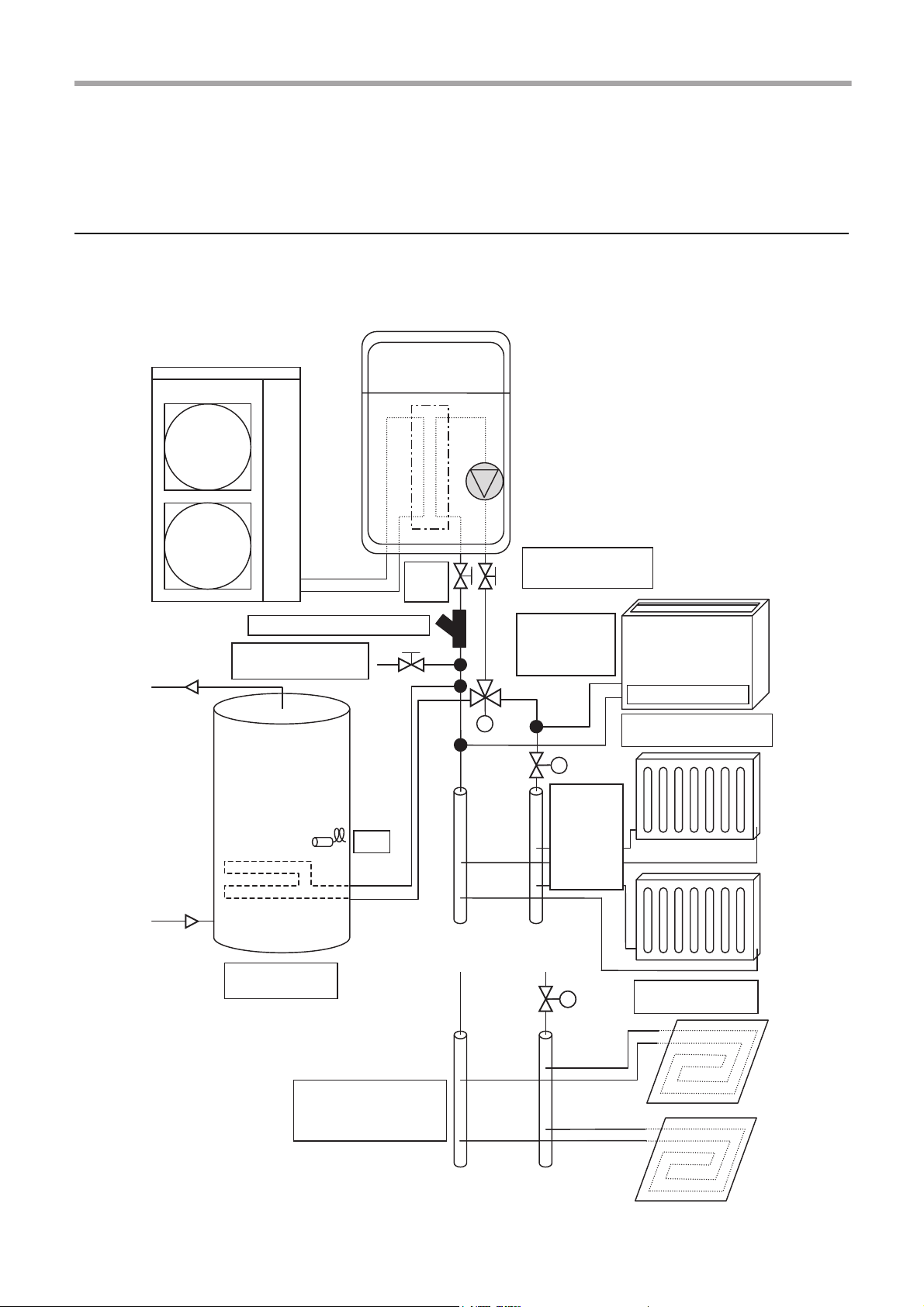
Fan Coil Units
(Cooling or Heating)
Isolating
Ball
Valves
Strainer (40 mesh / 0.4 mm)
Diverting 3-Way
Valve for
Sanitary Hot
Water Cylinder
Radiators (Heating Only)
[2-Way Valve Control]
2-Way
Valve
2-Way
Valve
Alternative to Radiators
Under-floor Heating
(Heating Only)
[2-Way Valve Control]
Indirect Sanitary
Hot Water Cylinder
Drain Cock for water
Charge and Drain
Use the 2way valve to
isolate the
heating
circuit when
in cooling
mode.
Use it when do not
operate cooling.
5
Example of Hydro Unit installation
Example of installation for cooling and heating
When both cooling and heating modes are required a 2-way valve must be installed to isolate the radiator or underfloor heating circuit.
▼ Fig. 5-01
TTW
M
M
M
–8–
8-EN
Page 10
Hydro Unit Installation Manual
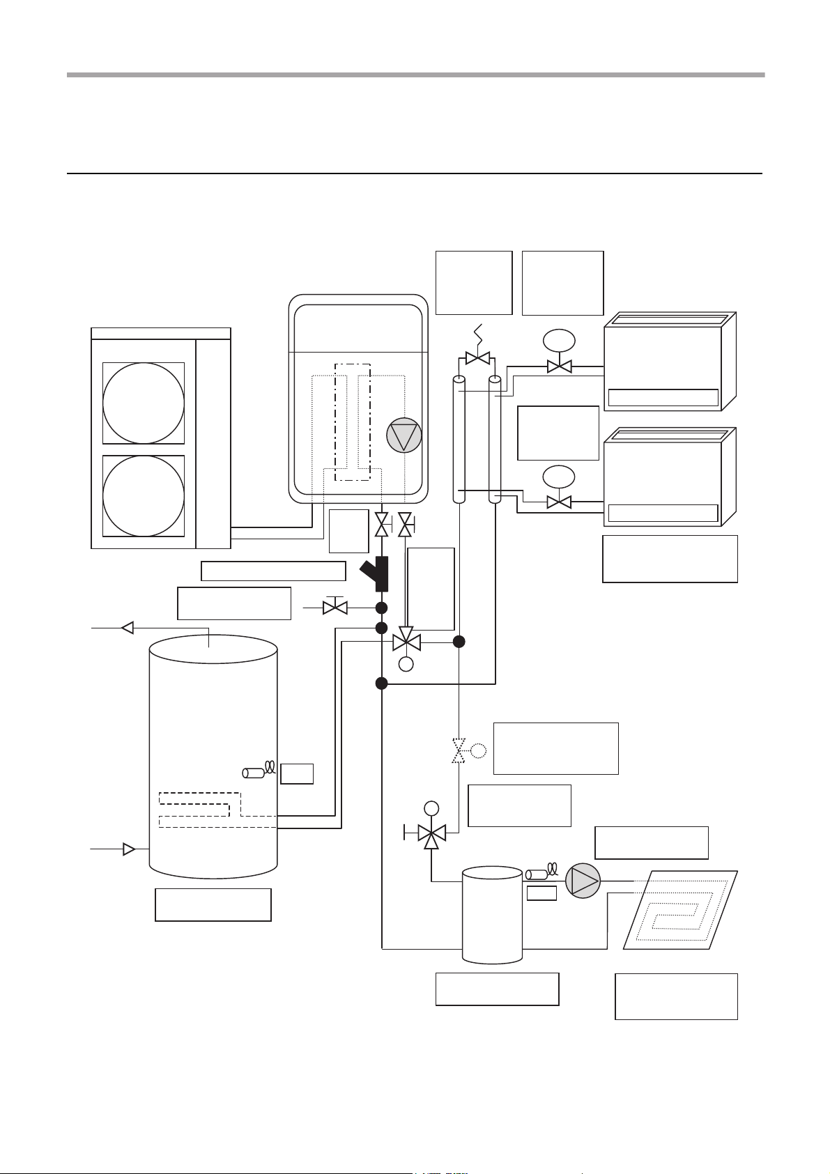
M
M
M
TTW
TFI
TRV
TRV
Temp.
Regulating
Valve
(Mechanical)
Isolating
Valves
(Service)
Strainer (40 mesh / 0.4 mm)
Diverting
3-Way
Valve for
Sanitary
Hot
Water
Cylinder
Drain Cock for water
Charge and Drain
Zone 1
Fan Coil Unit (Heating
or Cooling)
Temperature
Regulating
Valve
(Mechanical)
Hi-Pressure
By-Pass
Valve
Indirect Sanitary Hot
Water Cylinder
Mixing 3-Way
Valve for Under
Floor Heating
External Pump for
Under Floor Heating
Motorized 2-Way Valve
is required if fan coil
units are in cooling
operation.
Direct Buffer tank for
Under Floor Heating
Zone 2
Under-floor Heating
(2-Way Valve Control)
Example of 2-zone temperature control and hot water supply
system
The following shows an example of the 2-zone temperature control.
A buffer tank and a water pump are required for the 2-zone temperature control.
▼ Fig. 5-02
9-EN
–9–
Page 11
Hydro Unit Installation Manual
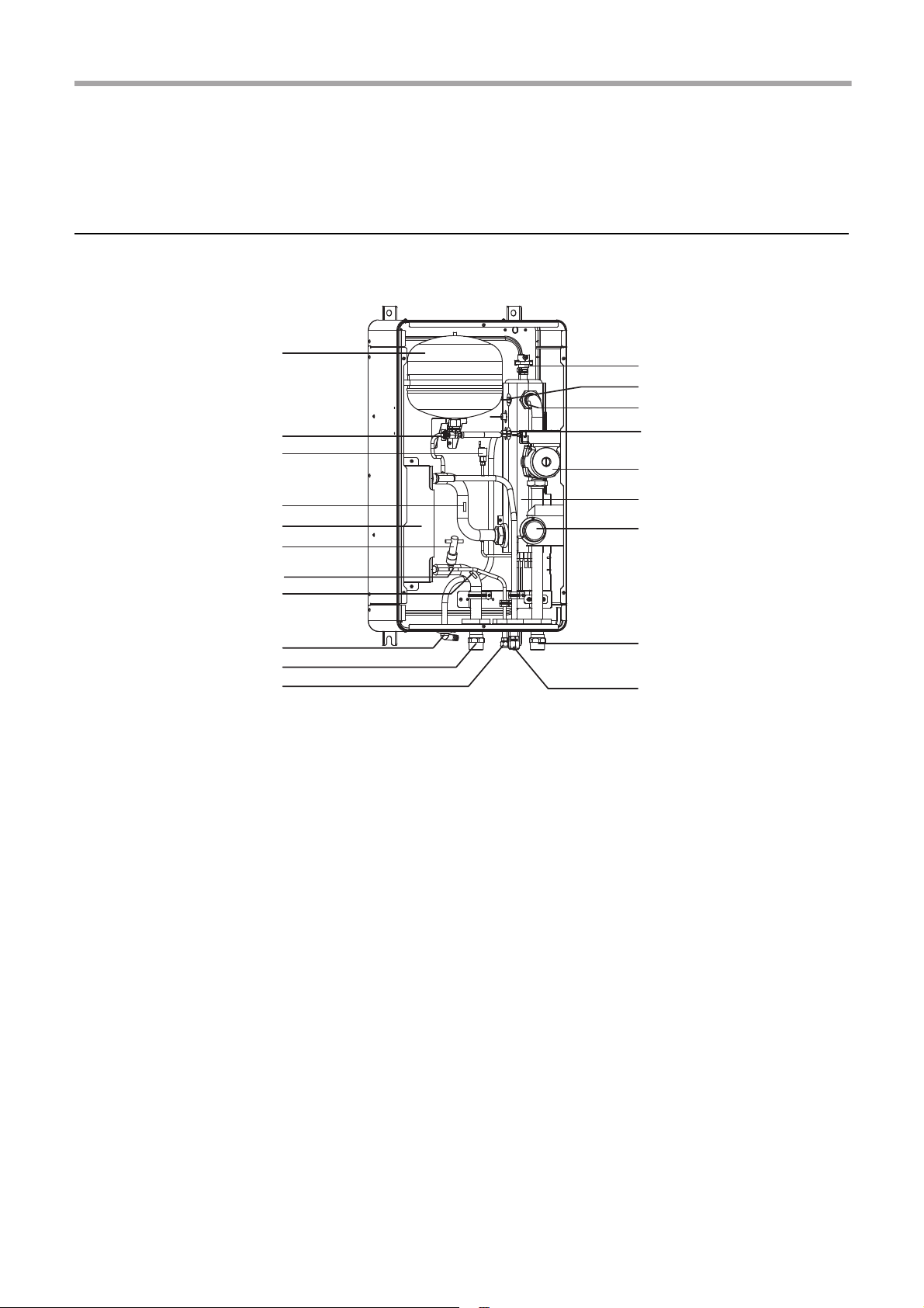
5
10
12
8
9
6
7
3
2
1
19
20
14
16
18
17
15
13
11
4
6
Main components of Hydro Unit
Exploded view and description for Hydro Unit
▼ Fig. 6-01
1 : Expansion vessel
2 : Temperature sensor (for Heat pump outlet -TWO)
3 : Pressure sensor
4 : Heat exchanger
5 : Flow switch (13 L/min (8 kW), 18 L/min (11 kW))
6 : Temperature sensor (for refrigerant -TC)
7 : Temperature sensor (for water inlet -TWI)
8 : Drain nipple
9 : Water inlet connection
10 : Refrigerant liquid connection
11 : Air relief valve
12 : Overpressure preventive valve (0.43 MPa (4.3 bar))
13 : Thermal protector (auto)
14 : Temperature sensor (for water outlet THO)
15 : Thermal protector (Single operation)
16 : Water pump
17 : Backup heater (3 kW, 3 kW x 2, 3 kW x 3)
18 : Manometer
19 : Water outlet connection
20 : Refrigerant gas connection
–10–
10-EN
Page 12
Hydro Unit Installation Manual
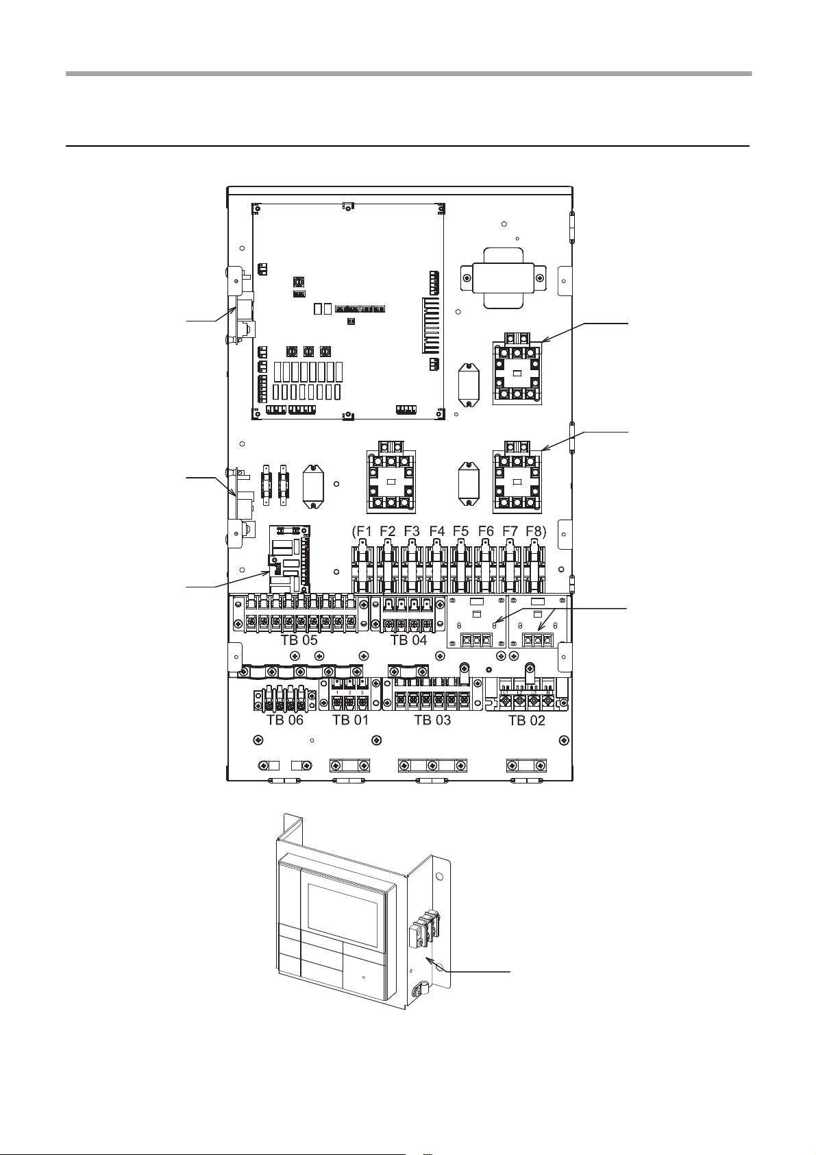
External output
P.C. board MCC1217 (Option)
External output
P.C. board MCC1217 (Option)
Relay P.C. board
MCC-1431
MG-SW (RY04)
MG-SW (RY02)
External input
P.C. board MCC1214 (Option)
Main P.C. board
MCC-1511
Trans
former
Relay
(RY06)
MG-SW (RY05)
Relay
(RY01)
Relay
(RY03)
Fuse
Fuse
(
F9 F10
)
TB 07
TB07
E-box layout
▼ Fig. 6-02
11-EN
–11–
Page 13
Hydro Unit Installation Manual
WARNING
CAUTION
NOTE
200 mm
100 mm
500 mm
350 mm
500 mm
380 mm
960 mm
M10
7
Hydro Unit installation
• To protect yourself from injury, always use PPE
(Personal Protective Equipment), that is, wear gloves.
• Install the Hydro Unit by at least two persons.
• Install the Hydro Unit in a place strong enough to
withstand the following weights:
The weight of the hydro units is displayed on the
product nameplate. When water enters the hydro unit,
it gets even heavier by about 20 kg.
• Do not install the unit in a place where water freezes.
• Do not install the Hydro Unit in a place where
combustible gas may leak.
• Do not install the Hydro Unit in a place exposed to rain
or water.
• Do not install the Hydro Unit near equipment which
generates heat.
• Do not install the Hydro Unit to a movable object.
• Do not install the Hydro Unit in a place exposed to
vibration.
• The unit must be installed in accordance with national
wiring regulation.
• The Hydro Unit must not be installed in a high humidity
condition area.
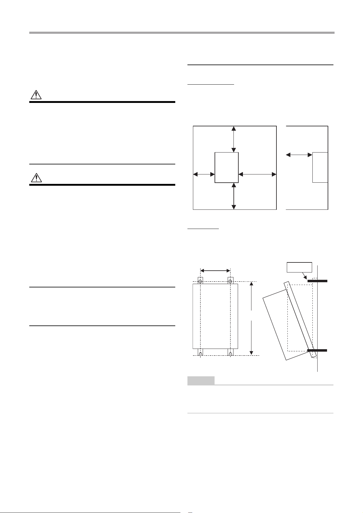
Positioning
Service space
Secure a service space for the Hydro Unit.
• Do not install the Hydro Unit in a place where heat
stagnates.
▼ Fig. 7-01
Mounting
Install M10 bolts at the positions shown below and
secure them with nuts.
▼ Fig. 7-02
Handling, unpacking, and
checking the Hydro Unit
• The unit should be checked when it is delivered, and
any damage reported immediately to the courier
claims the department.
If customer worried about vibration of Hydro Unit,
please insert vibration isolating material between the
product and the wall, when installing the product.
–12–
12-EN
Page 14
Hydro Unit Installation Manual
WARNING
CAUTION
NOTE
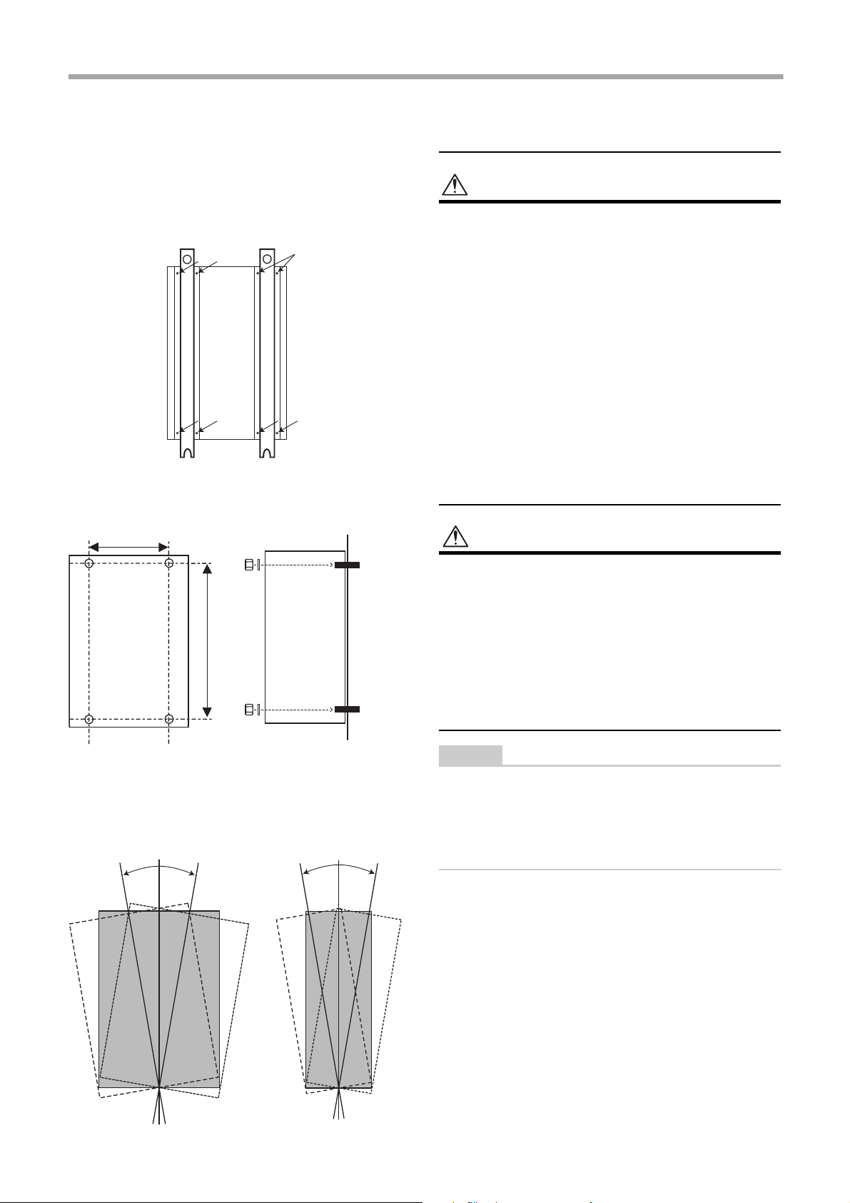
Remove the M5a screws to
detach the fixing angles.
380
860
M10
M10
Secure the Hydro Unit with
plain washers and nuts.
▼ Fig. 7-04
▼ Fig. 7-05
± 1°
▼ Fig. 7-06
▼ Fig. 7-07
The Hydro Unit can be installed directly without using
the fixing angles.
However, the back side of the Hydro Unit can be highly
heated, therefore, the installing surface must be heatresistant.
▼ Fig. 7-03
Refrigerant piping
• THIS SYSTEM ADOPTS HFC REFRIGERANT
(R410A) WHICH DOES NOT DESTROY THE
OZONE LAYER.
• The characteristics of R410A refrigerant are: ease to
absorb water, oxidizing membrane or oil, and its
pressure is approximately 1.6 times higher that of
R22. Accompanied with the new refrigerant the oil has
also been changed. Therefore during installation work
prevention of the invasion of water, dust, former
refrigerant or oil is of a paramount importance.
To prevent the charging of incorrect refrigerants into
the system the service valve connection ports have
also increased in size.
• The use of R410A tools is required for correct
installation of the system.
• The use of the correct pipe sizes and wall thicknesses
of copper pipe work is required for the correct
installation of the system.
Install the Hydro Unit so that its tilting angle falls within
the range below.
± 1°
• Ensure all refrigerant pipes are protected from the
invasion of dust and water.
• Ensure all pipe work connections are tightened to the
required torque settings detailed in this section.
• Perform an air tight using Oxygen Free Nitrogen
(OFN) only.
• Evacuate the air in the pipe work using a vacuum
pump.
• Check for refrigerant gas leaks at all connections
throughout the pipe work.
The Air to Water Heat Pump system uses R410A
refrigerant. It is important that copper pipes used for
refrigerant piping have the following wall thickness:
• 0.8 mm for Ø6.4 mm, Ø9.5 mm and Ø12.7 mm
• 1.0 mm for Ø15.9 mm
13-EN
–13–
Page 15
Hydro Unit Installation Manual
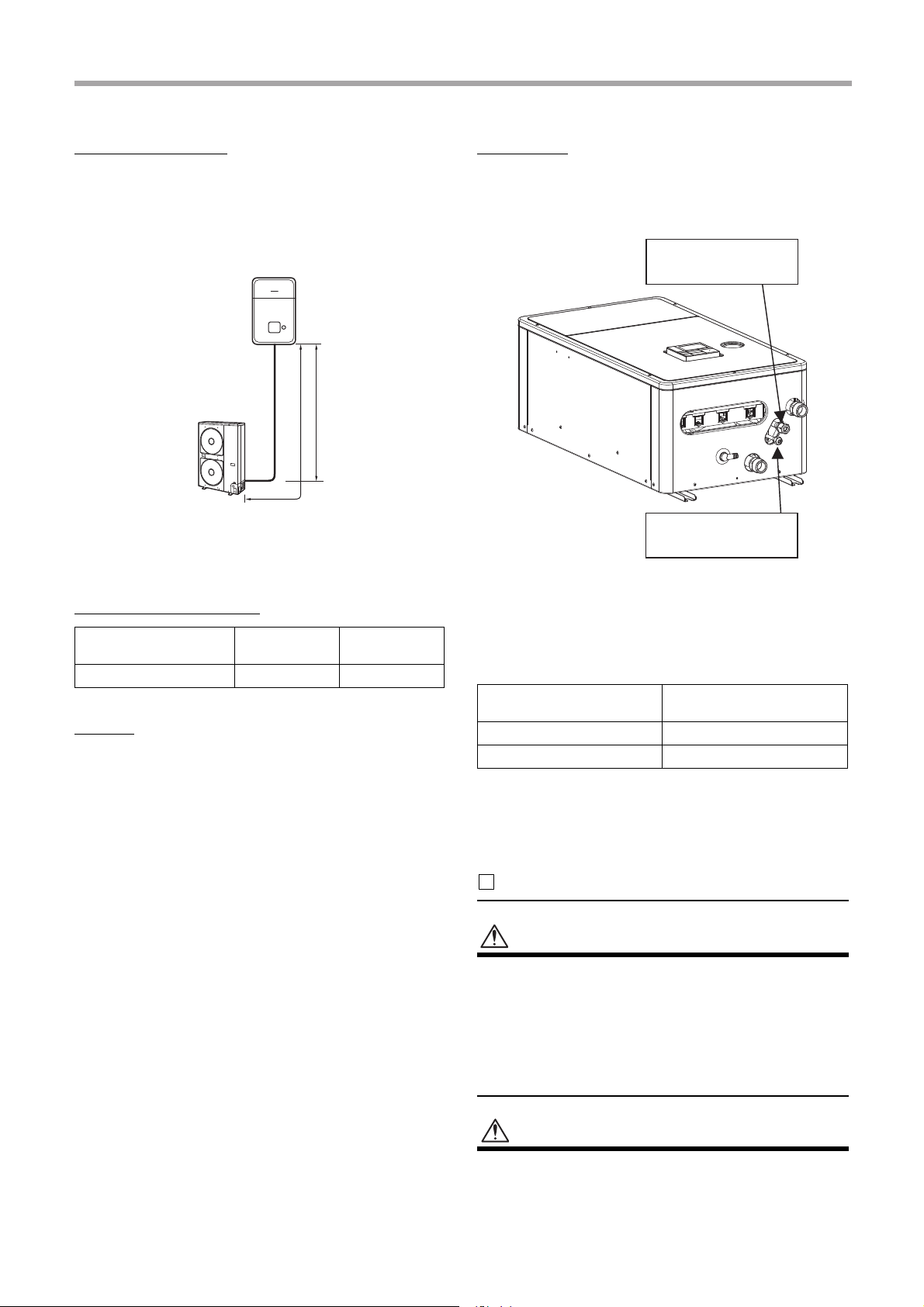
Refrigeration pipe
The length and height of the refrigeration pipe must be
within the following values.
As long as the Hydro Unit is installed within these
ranges, no additional refrigerant is required.
▼ Fig. 7-08
Outdoor unit
L
H
H: Max. ±30 m (above or below)
L: Max. 30 m
Min. 5 m
Refrigerant pipe sizes
Hydro Unit Model Gas Side (mm)
8 & 11 kW Hydro Unit Ø 15.88 Ø 9.52
Liquid Side
(mm)
Flaring
• Cut the refrigerant pipes to the correct length using a
pipe cutter. Remove any burrs that may be on the
pipes as these may cause refrigerant leaks or
component failure in the refrigeration cycle.
• Place the correct size flare nuts onto the pipes (use
the flare nuts supplied with the Hydro Unit or use
flare nuts designed specifically for R410A
refrigerant) and then flare the pipes using the correct
flaring tool.
Tightening
• Connect the refrigerant pipes, from the outdoor unit,
to the Hydro Unit as shown below.
▼ Fig. 7-09
Gas line Ø 15.88
Liquid line Ø 9.52
• Align the flare connection on each pipe with the
corresponding outlet connection on the Hydro Unit.
Tighten the flare nuts, using fingers, to secure the
pipes in place.
• Tighten the flare nuts, using a torque wrench, to the
tightening torques shown below:
Outer Ø of Copper Pipe
(mm)
9.5 33 to 42
15.9 63 to 77
Tightening Torque (N/m)
• To prevent damage, to the refrigerant pipes, use two
spanners to tighten the flare nut connections to the
required torque.
Water pipe
WARNING
• Install water pipes according to the regulations of
respective countries.
• Install water pipes in a freeze-free place.
• Make sure that water pipes have sufficient pressure
resistance.
The setting value of the overpressure preventive valve
is 0.43 MPa. (4.3 bar)
CAUTION
• Do not use zinc plated water pipes. When steel pipes
are used, insulate both ends of the pipes.
–14–
14-EN
Page 16
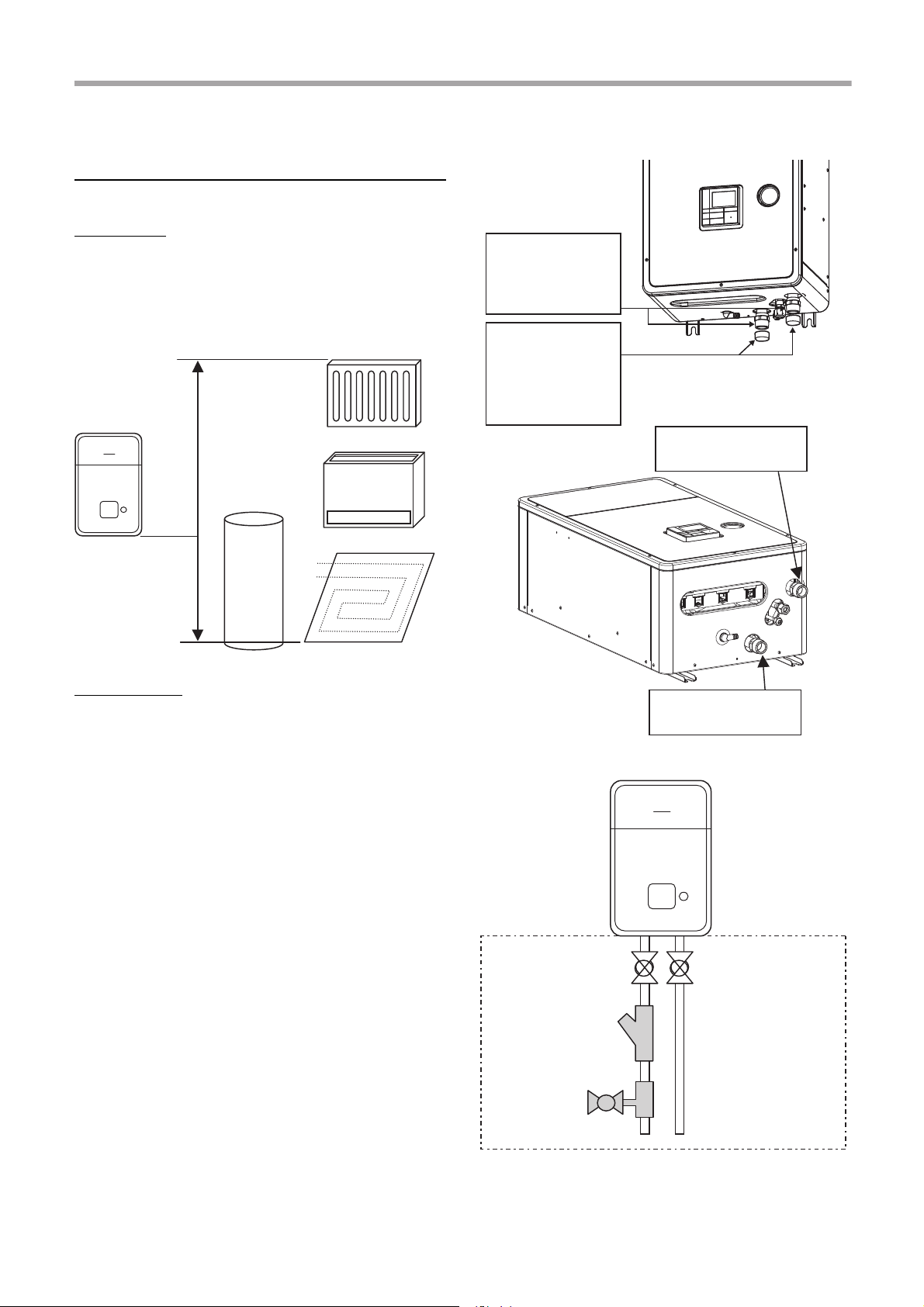
Hydro Unit Installation Manual
H < 7 m
Hot water outlet
connection 1 1/4"
Water inlet connection
1 1/4"
Attention
To avoid water leak,
exchange the seal
tapes to new one.
Attention
Water (used at test
in factory before
shipping) may be
found in the caps.
Local arrangement
Isolating Ball Valve
Strainer (30 to 40
meshes)
Drain cock for
water charge
and discharge
Inlet
• The water to be used must meet the water quality
standard specified in EN directive 98/83 EC.
Water pipe
Design the water pipe length within the QH
characteristics of the pump (Refer to “Fig. 7-16” and “Fig.
7-17” on page 17).
The height of the pipe must be 7 m or less.
▼ Fig.7-10
▼ Fig. 7-11
Water circuit
• Install a strainer with 30 to 40 meshes (locally
procured) at the water inlet of the Hydro Unit.
• Install drain cocks (locally procured) for water charge
and discharge at the lower part of the Hydro Unit.
• Make the piping route a closed circuit. (An open
water circuit may cause a failure.)
▼ Fig. 7-12
15-EN
–15–
Page 17
Hydro Unit Installation Manual
A
B
AB
to hydro unit
room heating or cooling
to hot water cylinder
Open when deenergized
Open when energized
A
B
AB
Motorized mixing valve
(locally procured)
from hydro
unit
Buffer tank (locally
procured)
Zone
2
Water pump
(locally procured)
to hydro unit
0
2
4
6
8
10
12
14
16
18
0 5 0 100 150
250200 300
*In case the maximum hot water temperature is 60ºC
V: Necessary total tank capacity( )
Vs: Total water amount in the system( )
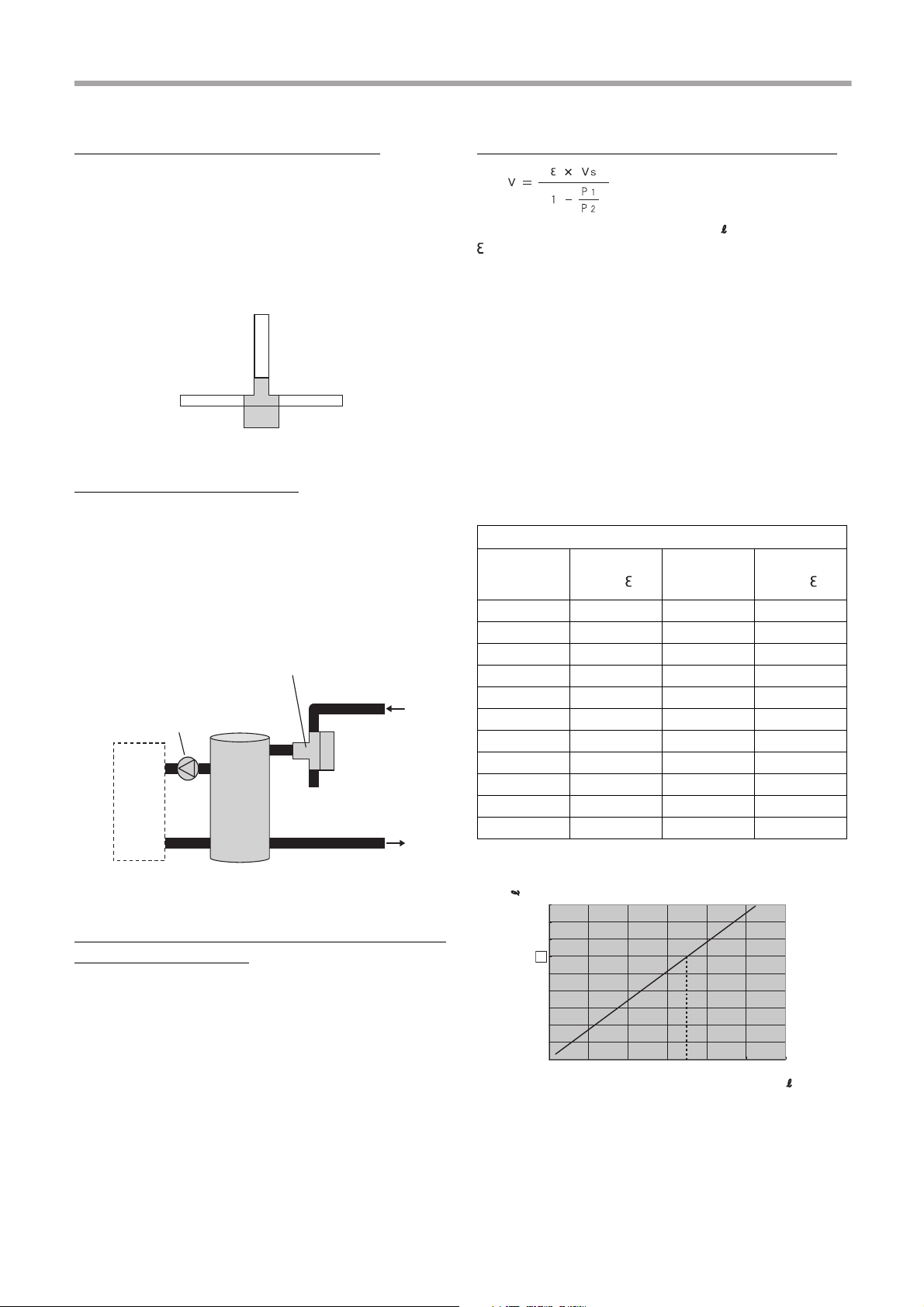
Piping to hot water cylinder (option)
Water supplied to the hot water cylinder is branched by
a motorized 3-way valve (locally procured).
For the specifications of the motorized 3-way valve,
refer to “Control parts specifications” on page 21.
Connect the hot water cylinder to port A (open when
energized) of the valve.
▼ Fig. 7-13
Piping to 2-zone operation
To perform 2-zone temperature control, circulate water
by another pump (locally procured) through a
motorized mixing valve (locally procured) and a buffer
tank (locally procured).
For the specifications of the motorized mixing valve,
Refer to “Control parts specifications” on page 21.
▼ Fig. 7-14
Expression for expansion vessel selection
V: Necessary total tank capacity ( )
: Water expansion coefficient at each hot water
temperature
Vs: Total water amount in the system
P1: System pressure at tank setting position
(MPaabs.)
= water supply pressure = 0.3 (MPaabs.)
(recommended valve)
P2: Maximum pressure used during operation at tank
setting position (MPaabs.)
= safety valve setting pressure = 0.4 (MPaabs.)
* The absolute pressure value (abs.) is obtained by
adding the atmospheric pressure (0.1 MPa (1 bar))
to the gauge pressure.
▼ Tank selection method
Water temperature and expansion coefficient
Hot water
temperature
(°C)
0 0.0002 50 0.0121
4 0.0000 55 0.0145
5 0.0000 60 0.0171
10 0.0003 65 0.0198
15 0.0008 70 0.0229
20 0.0017 75 0.0258
25 0.0029 80 0.0292
30 0.0043 85 0.0324
35 0.0050 90 0.0361
40 0.0078
45 0.0100
Expansion
rate
Hot water
temperature
(°C)
Expansion
rate
Checking water volume and initial pressure
of expansion vessel
The expansion vessel of the Hydro Unit has a capacity
of 12 liters.
The initial pressure of the expansion vessel is
0.15 MPa (1.5 bar).
The pressure of the safety valve is 0.43 MPa (4.3 bar).
Verify whether the capacity of the expansion vessel is
sufficient using the following expression. If the volume
is insufficient, add the capacity locally.
▼ Fig. 7-15
Install an external expansion vessel when the capacity
of the expansion vessel is insufficient.
–16–
16-EN
Page 18
Hydro Unit Installation Manual
0 5 10 15 20 25 30 35
0
1
2
3
4
5
6
7
8
9
10
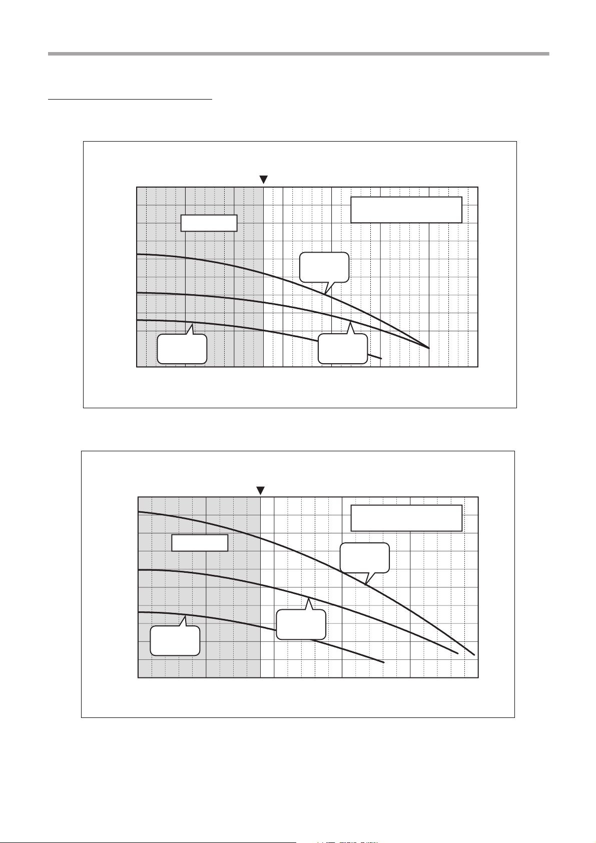
Hydraulic heat exchanger (8 kW) QH characteristics
Minimum flow rate
Head [m]
Out of range
Hydro unit QHCharacteristics (220/230 V)
Pump duty
100%
Pump duty
60%
Pump duty
80%
Flow rate [L/min]
0
1
2
3
4
5
6
7
8
9
10
0 1020304050
Head [m]
Hydraulic heat exchanger (11 kW) QH characteristics
Minimum flow rate
Hydro unit QHCharacteristics (220/230 V)
Out of range
Pump duty
100%
Pump duty
60%
Pump duty
80%
Flow rate [L/min]
Pump operation/configuration
▼ Fig. 7-16
▼ Fig. 7-17
17-EN
–17–
Page 19
Hydro Unit Installation Manual
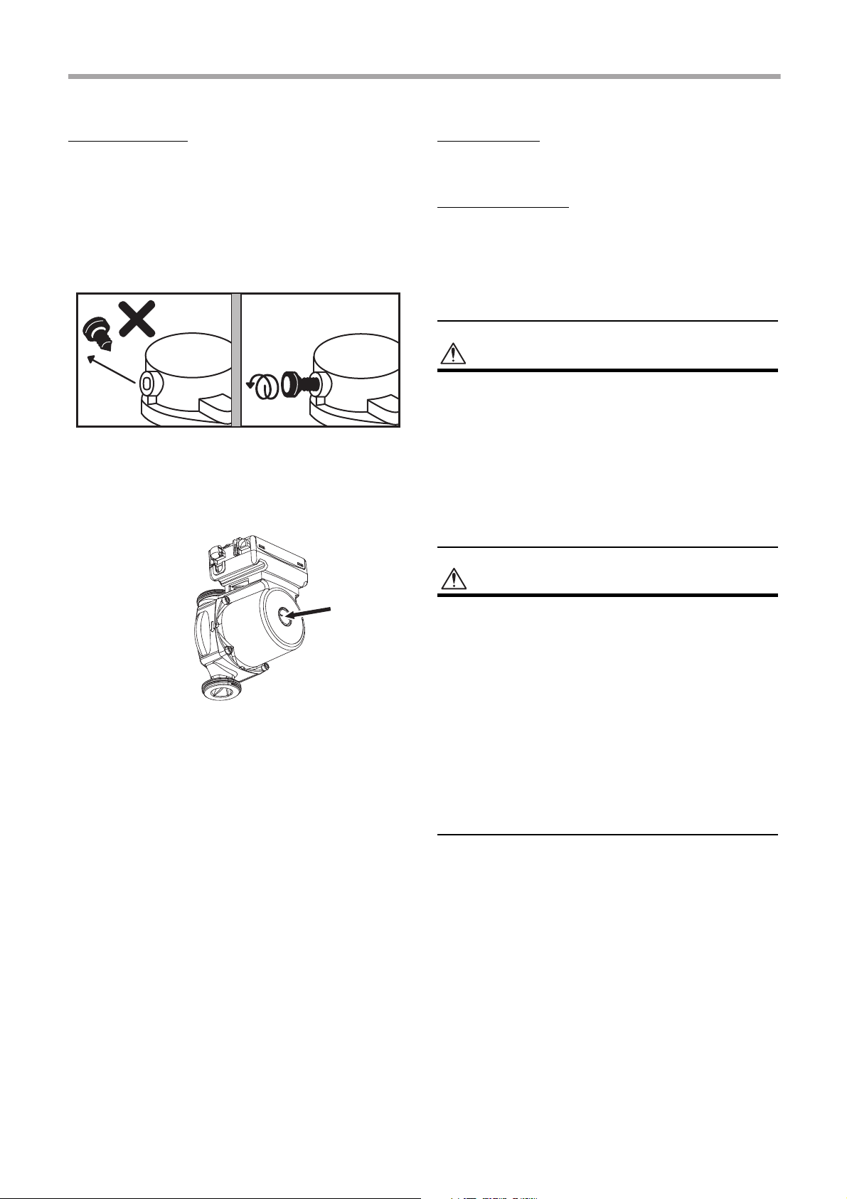
WARNING
CAUTION
Loosen 2 turns for
proper venting
* Purge valve cap faces the front as factory default.
* The direction purge valve cap may change during
transportation.
Water charging
Charge water until the pressure gauge shows
recommended valve 0.2 MPa (2 bar).
Hydraulic pressure may drop when the trial run begins.
In that case, add water.
Air may enter if the charged hydraulic pressure is low.
Loosen the purge valve cap by two turns to release air.
▼ Fig. 7-18
Water quality
The water used must satisfy EN directive 98/83 EC.
Piping insulation
It is recommended that insulation treatment be applied
to all pipes. To perform optional cooling operation,
apply insulation treatment of 20 t or more to all pipes.
Electrical installation
• Ensure electrical circuits are isolated before
commencing the electrical installation.
• The electrical installation must be completed by a
qualified electrician.
• The electrical installation must comply to all Local,
National and International electrical installation
regulations.
• This product must be earthed in accordance with
Local, National and International electrical installation
regulations.
Loosen the air vent screw of the pump, pull out air in
the pump, and tighten again.
Loosen the cap of the pressure relief valve to release
air.
Water may come out of the pressure relief valve.
Release the air completely from the water circuit.
Failure to do so may disable correct operation.
• The Hydro Unit must be connected to a dedicated
power supply for the back up heater circuit.
• The electrical supply must be protected by a suitably
sized over current protection device (fuse, MCB etc)
and an earth leakage protection device.
• The Hydro Unit must be connected to the mains power
supply using a isolating switch which disconnects all
poles and has a contact separation of at least 3 mm.
• The cord clamps, attached to the Hydro Unit, must be
used to secure the electrical cables.
• Wrong connection of electrical cables may result in
electrical component failure or fire.
• Ensure the electrical cables are sized in accordance
with the installation instructions.
–18–
18-EN
Page 20
Hydro Unit Installation Manual
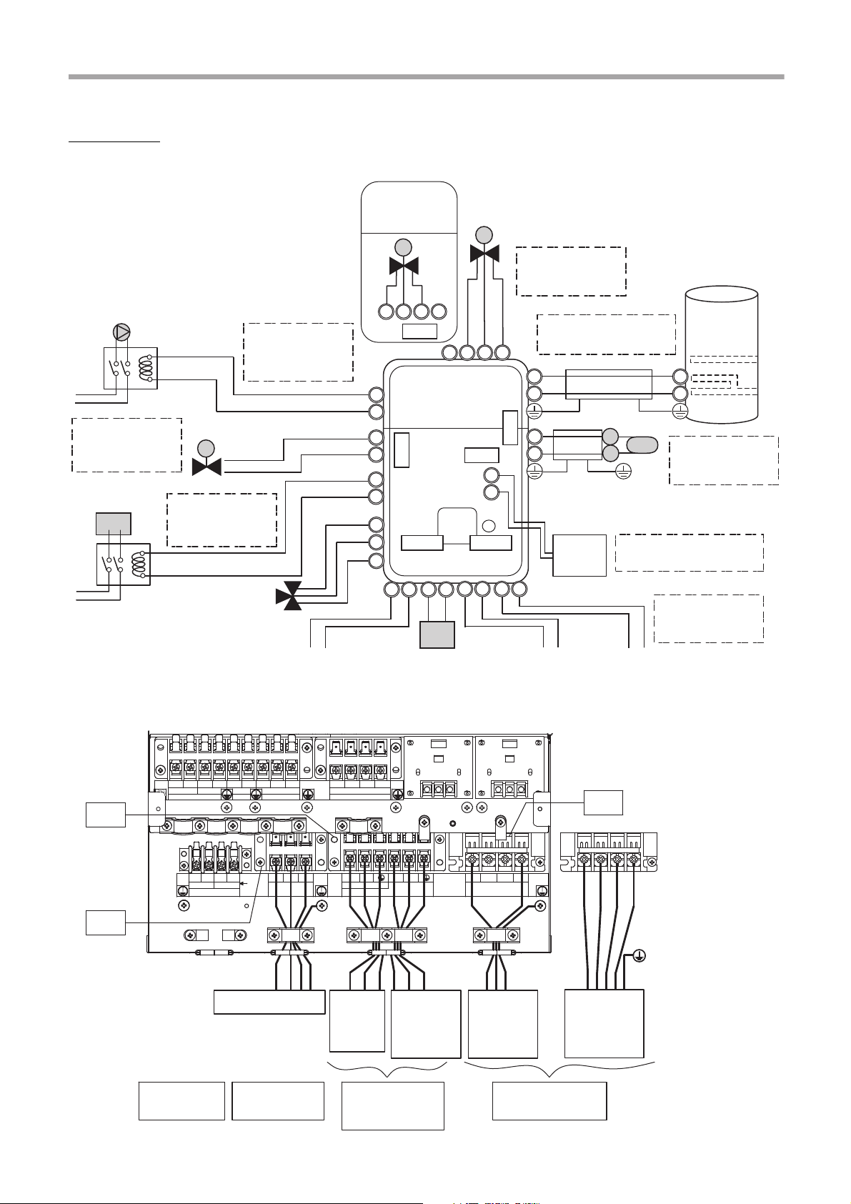
TB07
A
B
C
D
1
2
3
4
5
6
A
B
1
2
3
4
1
2
3
4
1
2
3
4
TB05
PJ20
PJ20
TB06
CN208
OPTION OPTION
CN209
1
2
7
8
9
1
2
3
4
TB04
CW
CCW
N
Mixing-Valve
type 2 for 2 zone
control
Max 12 m
230 V 100 mA
0.75 mm² or more
Mixing-Valve type 1
for 2 zone control
Max 5 m shielded wire
0.75 mm² or more
Temp sensor in hot
water cylinder
Max 12 m
230 V 1 A
0.75 mm² or more
Pump (local)
Max 12 m
230 V 100 mA
0.75 mm² or more
Booster heater
(local)
Max 12 m
230 V 1 A
0.75 mm² or more
Alert output
(local)
Boiler operation
(local)
Defrost output
(local)
Compressor
operation output
(local)
Max 12 m non
voltage 0.75 mm² or
more
Temp sensor for
2 zone control
Max 5 m shielded
wire 0.75 mm² or
more
2Way-Valve for
cooling stop
3Way-Valve for hot
water cylinder
Max 50 m
0.50 mm² or more
2nd remote controller
6B6A 6D
6C
TF1
TB 06
11 12
13
TB 01
Don't apply
220-240V
or
breakdown
will occur.
TTW
31 32
L
TB 03
HOT WATER CYLINDER
L
TB 02
N
1
3
2
L2L1
L3
N
WPM
51
TB 05
52
41
MIXV
53
54
55
565758
59
2WV
BH
3WV
42
43
44
TB 04
N
L3
L1 L2
N
TB03
TB01
TB02
Input power
380-400 V 3N
~ 50 Hz
Input power
220-230 V ~
50 Hz
Input power
220-230 V ~
50 Hz
Hot
water
cylinder
to Outdoor unit
Hot water cylinder
power supply
Outdoor unit
connection
Sensor
connection
Backup heater
power supply
Control line
▼ Fig. 7-19
▼ Fig. 7-20
19-EN
–19–
Page 21

Hydro Unit Installation Manual
Electrical supply/cable specifications
▼ Wiring specifications
Description
Outdoor
unit
power
Hydro
inlet
heater
power
Outdoor-Hydro unit Connection 1.5 mm² or more , , TB01
Hydro -Cylinder Connection 1.5 mm² or more , TB03
Power
input
Power
input for
backup
heater
Power input for cylinder
heater
Model name
HWS-
P1105HR-E
P805HR-E
P1405H8R-E
P1105H8R-E
P805H8R-E
P1105XWHM3-E
P1105XWHT6-E
P1105XWHT9-E
P805XWHM3-E
P805XWHT6-E
P805XWHT9-E
POWER
SUPPLY
220-230 V ~
50 Hz
220-230 V ~
50 Hz
380-400 V 3N~
50 Hz
380-400 V 3N~
50 Hz
380-400 V 3N~
50 Hz
220-230 V ~
50 Hz
380-400 V 3N~
50 Hz
380-400 V 3N~
50 Hz
220-230 V ~
50 Hz
380-400 V
3N~ 50 Hz
380-400 V
3N~ 50 Hz
220-230 V ~
50 Hz
Maximum
current
22.8 A 25 A 4 mm² or more
22.8 A 25 A 4 mm² or more
14.6 A 16 A 2.5 mm² or more
14.6 A 16 A 2.5 mm² or more
14.6 A 16 A 2.5 mm² or more
13 A 16 A 1.5 mm² or more ,
13 A(13 A x 2P) 16 A 1.5 mm² or more
13 A(13 A x 3P) 16 A 1.5 mm² or more
13 A 16 A 1.5 mm² or more
13 A(13 A x 2P) 16 A 1.5 mm² or more
13 A(13 A x 3P) 16 A 1.5 mm² or more
12 A 16 A 1.5 mm² or more
Installation
fuse rating
Power wire Connection destination
,
, ,
,
, ,
,
,
, ,
,
,
TB02
TB03
▼ Wiring specifications (control line)
Description Line spec
Maximum
current
Maximum length
3-way valve control 2 line or 3 line 100 mA 12 m 0.75 mm² or more
2-way valve control 2 line 100 mA 12 m 0.75 mm² or more , (TB05)
Mixing valve control 3 line 100 mA 12 m 0.75 mm² or more
2-zone thermo sensor 2 line 100 mA 5 m 0.75 mm² or more , (TB06)
Cylinder thermo sensor
2+GND(shielded
wire)
100 mA 5 m 0.75 mm² or more , (TB06)
Second remote controller 2 line 50 mA 50 m 0.5 mm² or more , (TB07)
Group control (total) 2 line 50 mA 50 m 0.5 mm² or more , (TB07)
Open protocol interface 2 line 100 mA 50 m 0.5 mm² or more , (TB07)
Connection
destination
, ,
(TB05)
, ,
or
, ,
(TB04)
–20–
20-EN
Page 22

Hydro Unit Installation Manual
CAUTION
▼ Control parts specifications
Power Maximum current Type
Motorized 3-way valve
(for hot water)
Motorized 2-way valve
(for cooling)
Motorized mixing valve
(for 2-zone)
AC 230 V 100 mA
AC 230 V 100 mA spring return type (normally open)
AC 230 V 100 mA
Default: 2-wire spring return valve or 3 wire SPST valve
Note: 3 wire SPDT valve can be used by changing DIP switch
13_1.
Default: Drive time = 60sec to 90°
Note: 3 wire SPST or SPDT valves, with drive times between
30 and 240 seconds, can be used. Valve drive time can be
changed using function code 0C
▼ Output line specifications
Description Output
External pump No.1 AC230 V 1 A – 12 m
External boost heater AC230 V 1 A – 12 m
Boiler control
ALARM Output
Compressor operation
output
Defrost Output
Non-voltage
contacts
Non-voltage
contacts
Non-voltage
contacts
Non-voltage
contacts
Maximum
current
0.5 A AC230 V 12 m Output as required when outdoor air
1 A DC24 V 12 m
0.5 A AC230 V 12 m
1 A DC24 V 12 m
0.5 A AC230 V 12 m
1 A DC24 V 12 m
0.5 A AC230 V 12 m
1 A DC24 V 12 m
Max
voltage
Maximum
length
Output as required when outdoor air
temperature is -20 °C or less
temperature is -10 °C or less. The
outdoor air temperature, when the
boiler output is enabled, can be
changed using function code 23.
▼ Input line specifications
Description Input Maximum length
Emergency stop control Non-voltage 12 m
Cooling thermostat input Non-voltage 12 m
Heating thermostat input Non-voltage 12 m
Earthing arrangements
The Hydro Unit and related equipment must be earthed in accordance with your local and national electrical regulations.
It is essential that the equipment is earthed to prevent the electric shock and damage to the equipment.
21-EN
–21–
Page 23

Hydro Unit Installation Manual
L N L1 L2 L3 N
TB02TB02
▼ Fig. 7-21
Leakage
breaker
30 mA
Leakage
breaker
30 mA
Input power
220-230 V
50 Hz
Backup heater
220-230 V ~ type
(3 kW type)
Backup heater
380-400 V 3N~
type
(6,9 kW type)
Input power
220-230 V
3N~ 50 Hz
N
L
1
3
2
1
3
2
TB01
Leakage
breaker
30 mA
Input
power
220-230 V
~ 50 Hz
Outdoor unit Hydro unit
Electrical connection to hydro unit
• Remove the front cover and the electrical box cover
from the Hydro Unit.
• The Hydro Unit power cable must be sized in
accordance with refer to “Electrical supply/cable
specifications”.
• Connect the Hydro Unit power cable to Terminal 02
as shown below.
• Ensure the Hydro Unit power cable is secured using
the cable clamp fitted in the electrical box.
• Ensure the Hydro Unit power cable connection
terminals are tight.
Outdoor unit to hydro unit electrical
connection
▼ Fig. 7-22
• Ensure electrical circuits are isolated before
commencing work.
• The Outdoor Unit to Hydro Unit interconnecting
cable must be sized in accordance with refer to
“Electrical supply/cable specifications”.
• Connect the Outdoor Unit to Hydro Unit
interconnecting cable as shown in the diagram
above.
• Ensure the Outdoor Unit to Hydro Unit
interconnecting cable is secured using the cable
clamp fitted in the electrical box.
• Ensure the Outdoor Unit to Hydro Unit
interconnecting cable connection terminals are tight.
–22–
22-EN
Page 24

Hydro Unit Installation Manual
CAUTION
1234567 8 9
Terminal Block 05
Booster Heater
Terminal Block 05
Pump
Electrical connection for external booster
heater
• The maximum current available from the
booster heater output is 1
the booster heater directly to Terminal Block
05 on the Hydro Unit. A separate contactor,
supplied locally, must be used to supply the
booster heater.
• The booster heater can be installed only for room
heating and cannot be used for hot water supply.
• Install the booster heater downstream of the 3-way
valve on the indoor unit side.
The booster heater is an external heater, supplied
locally, used to assist the Hydro Unit during low
ambient conditions.
• The AC230
be used to energize an external contactor. (Supplied
locally)
• The output from the Hydro Unit is only enabled when
the outdoor air temperature is less than -20 °C.
• Ensure the external booster heater is installed and set
up in accordance with all Local, National and
International regulations.
V 1 A output from the Hydro Unit must only
A. Do not connect
Electrical connection for external additional
pumps
• The Hydro Unit has the facility to connect an
additional circulating pump, if required, into the
heating or cooling system.
• There is an output available from the Hydro Unit.
AC230 V 1 A (maximum) is available from each
output. The output for each additional pump is
synchronized with the operation of the main
circulating pump inside the Hydro Unit.
• Connect the additional pumps as shown in the
diagram below.
• Connect external pump 1 to terminals 1 & 2 on
Terminal Block 05.
• Install external pumps so that their motive power
does not affect the internal pump.
▼ Fig. 7-24
01
• Connect the external booster heater to the Hydro
Unit in accordance with the diagram shown below.
• Connect the coil, of the field supplied contactor, to
terminals 5 & 6 on Terminal Block 05. The contactor
will energize in the event of low ambient conditions.
• A separate dedicated electrical supply must be used
for the external booster heater. This must be
connected through the contacts on the field supplied
contactor.
▼ Fig. 7-23
1234567 8 9
23-EN
–23–
Page 25

Hydro Unit Installation Manual
NOTE
7
8
9
Type 1: SPRING RETURN
port “A” to Hot water
cylinder
port “AB” to
Hydro unit
port “B” to Room heating
or cooling
port “A” open
Hydro Unit
TB 05
7
8
9
Type 2: SPST
port “A” to Hot water
cylinder
port “AB” to
Hydro unit
port “B” to Room heating
or cooling
port “A”
close
open
Hydro Unit
TB 05
Type 3: SPDT
port “A” to Hot water
cylinder
port “AB” to
Hydro unit
port “B” to Room heating
or cooling
port “A”
close
open
Hydro Unit
TB 05
3-way
valve (diverter) connection
Required Valve Specification:
Electrical Specification: 230 V; 50 Hz; <100 mA
Valve Diameters: Port A, Port B: Ø 1 1/4"
Return Mechanism: 3 types of 3-way valve (diverter)
can be used.
Set the 3-way valve in use with the DIP switch SW131 on the Hydro Unit board.
SW13-1
Type 1 2-wire spring return OFF
Type 2 3-wire SPST OFF
Type 3 3-wire SPDT ON
Continuous operation of the valve motor at the fully
open position is not recommended.
• The 3-way diverter valve is used to select either
domestic hot water or space heating.
• Connect the 3-way diverter valve to terminals 7, 8
and 9 on Terminal Block 05.
• Connect the 3-way diverter valve in accordance with
the diagram below:
▼ Fig. 7-26
▼ Fig. 7-27
7
▼ Fig. 7-25
8
9
–24–
24-EN
Page 26

Hydro Unit Installation Manual
Type 1: SPDT
2
1
3
4
port “A” to Zone 2 Heating
port “AB” to
Hydro unit
port “B” BLANK OFF
port “A”
close
open
Hydro Unit
TB 04
2
1
3
4
Type 2: SPST
port “A” to Zone 2 Heating
port “AB” to
Hydro unit
port “B” BLANK OFF
port “A”
close
open
Hydro Unit
TB 04
12 LN
1
2
Earth leakage breaker
INPUT Power
220-230 V ~
50 Hz
Terminal block 03
Hot water
cylinder
3-way mixing valve connection
Required Actuator Specification
Electrical Specification:230 V; 50 Hz; <100 mA
The 3-way mixing valve is used to achieve the
temperature differential needed in a 2-zone heating
system.
• Connect the 3-way mixing valve to terminals 2, 3 and
4 on Terminal Block 04 (for Type 1 mixing valve) or
on terminals 1, 2 and 3 on Terminal Block 04 (for
Type 2 mixing valve).
• Connect the 3-way mixing valve in accordance with
the diagrams below:
▼ Fig. 7-28
Hot water cylinder connection (optional)
• Please refer to “Electrical supply/cable
specifications” for fuse/cable size and for
connection details.
Electrical Connection (Hot Water Cylinder
Electric Heater)
• The electric heater, incorporated in the hot water
cylinder, requires a separate supply to Hydro Unit.
• Connect the hot water cylinder heater electrical
supply in accordance with shown below:
Live conductor: Terminal L on Terminal Block 03
Neutral conductor: Terminal N on Terminal Block 03
Earth Conductor: Earth terminal on Terminal Block
03
• Connect the hot water cylinder heater to the Hydro
Unit as shown below:
Live conductor to hot water cylinder: Terminal 1 on
Terminal Block 03
Neutral conductor to hot water cylinder: Terminal 2
on Terminal Block 03
Earth conductor to hot water cylinder: Earth terminal
on Terminal Block 03
▼ Fig. 7-29
▼ Fig. 7-30
25-EN
–25–
Page 27

Hydro Unit Installation Manual
Hydro unit
Locally procured
Power
Supply
Power
Supply
Display
Relay K1
Display
Relay K2
Connection Cable
OPERATION
EMG
Alarm
output
Boiler
control
output
Hydro unit
main control
board
Electrical Connection (Hot Water Cylinder
temperature Sensor)
• Connect the hot water cylinder temperature sensor
as shown below to terminals A & B on Terminal
Block 06 in the Hydro Unit.
• Please ensure that the interconnecting cable,
between the Hydro Unit and the hot water cylinder, is
connected to earth at both ends of the cable using
the shield wire.
▼ Fig. 7-31
Additional hydro unit outputs
Alarm and Boiler Outputs
Alarm Output: L1: Alarm output
• Output enabled when the system is in alarm/fault
condition.
• Volt free contact - specification shown below:
AC230 V; 0.5 A (maximum)
DC24 V; 1 A (maximum)
• Connection details: Terminals 1 and 2
(OPERATION) on MCC-1217 TB (Refer to “Fig. 732”)
Boiler Control Output: L2: Boiler drive permission
output
• Output enabled when outdoor ambient temperature
< -10 °C
• Volt free contact - specification shown below:
AC230 V; 0.5 A (maximum)
DC24 V; 1 A (maximum)
• Connection details: Terminals 3 and 4 (EMG) on
MCC-1217 TB (Refer to “Fig. 7-32”)
▼ Fig. 7-32
Group control
• When Group control is used, the Slave hydro unit is
also able to share the value of the Master hydro unit
TTW sensor. In this case TTW Connection of each
Slave hydro unit is not necessary.
• Set function code “FCAB” of each Slave hydro unit to
“1”.
• This function has been installed since January 2019
Hydro unit serial No. 901Y0001
.
TCB-PCIN3E
4
PJ20CN208
3
2
1
L2
L1
Defrost and Compressor operation Outputs
Defrost output
• Display relay is ON when the system defrost.
• Volt free contact
AC230 V; 0.5 A (maximum)
DC24 V; 1 A (maximum)
• Connection details: Terminals 1 and 2
(OPERATION) on MCC-1217 TB (Refer to “Fig. 733”)
–26–
26-EN
Page 28

Hydro Unit Installation Manual
CAUTION
CAUTION
PJ20CN209
TCB-PCIN3E
4
3
L2
2
1
L1
Defrost
output
Compressor
operation
output
Locally procured
Power
Supply
Power
Supply
Display
Relay K1
Display
Relay K2
Connection Cable
OPERATION
EMG
Hydro unit
main control
board
*1
1
2
3
PJ17
CN211
TCB-PCMO3E
Connection
Cable
COM
Locally procured
Thermostat
COOL
HEAT
Cool
Hot
Compressor operation output
• Display relay is ON with outdoor unit compressor
operation.
• Volt free contact
AC230 V; 0.5 A (maximum)
DC24 V; 1 A (maximum)
• Connection details: Terminals 3 and 4 (EMG) on
MCC-1217 TB (Refer to “Fig. 7-33”)
▼ Fig. 7-33
*1:Available to change the output signal by function
code 67.
Default (FC67 = 0) Setting value (FC67 = 1)
1 - 2 = Defrost output
3 - 4 = Compressor
operation output
1 - 2 = Alarm output
3 - 4 = During operation
• Be sure to prepare a non-voltage contact for each
terminal.
• Display Relay capacity of “EMG” and “OPERATION”.
Below AC230 V 0.5 A (COS
Ø
= 100%)
When connecting loads such as relay coil to “L1, L2”
load, insert noise surge absorber.
Below DC24 V 1 A (Non-inductive load)
When connecting load such as relay coil to “L1, L2”
load, insert the bypass circuit.
Optional inputs to hydro unit
Room Thermostat Input:
2–3: Room thermostat input for cooling mode
1–3: Room thermostat input for heating mode
• Output enabled when either heating or cooling mode
selected on room thermostat. (locally supplied)
• Volt free contacts
• Connection details:
Cooling Connection: Terminals 3 (COM) and 2
(COOL) on MCC-1214TB (Refer to “Fig. 7-34”)
Heating Connection: Terminals 3 (COM) and 1
(HEAT) on MCC-1214TB (Refer to “Fig. 7-34”)
• Setting of DIP switch on the Hydro Unit board:
DIP SW02_4 = ON
▼ Fig. 7-34
Thermostat operation
Cooling Heating
on off on off
2 - 3 open close – –
1 - 3 – – close open
• Be sure to prepare a non-voltage continuous contact
for each terminal.
• Supplementary Insulation must be added to user
touchable part of switches.
27-EN
–27–
Page 29

Hydro Unit Installation Manual
TCB-PCMO3E
Locally procured
Emergency Shutdown input
S2: Emergency stop input, Tempo* control input
This function can be switched over with FC21 and
FC61.
• Non-voltage contacts
• Connection details:
Emergency stop, Tempo* control ON: Terminals 3
(COM) and 1 (HEAT) on MCC-1214TB (Refer to
“Fig. 7-35”)
* a price contract provided by French electric power
company EDF
Hot water tank thermostat input
S1: Local hot water tank thermostat input
This function is used with DIP switch 2_3 is “ON”, when
the customer use the local hot water tank.
* Close: Not reached setting temperature.
* Open: Reached setting temperature.
(Refer to “Fig. 7-35”)
Control of force stop and restart
When Group control is used, the optional PC board
should be connected to the master hydro unit only.
Slave hydro units operate the same as the master
hydro unit.
1. Refer to “Fig.7-35”
S1: Hot water supply control
S2: Heating (Cooling) control
• This function is valid only when DIP switch 2_3 is
“OFF”.
• FC61 is set to “3” and FCB6 is set to “1”.
• Operation by external input can be switched over
with FC52. Set to “0” – “3”.
2. Refer to “Fig.7-35”
S1: Change the operating mode (Heating / Cooling)
S2: Heating (Cooling) control
• This function is valid only when DIP switch 2_3 is
“OFF”.
• FC61 is set to “3”, FCB6 is set to “2” and FC52 is set
to “2”.
• This function has been installed since January 2019
Hydro unit serial No. 901Y0001
.
▼ Fig. 7-35
Connection to a Smart Grid network (SG Ready)
• This function has been installed since January 2019
Hydro unit serial No. 901Y0001
.
• Refer to “Fig.7-35”
• The operating mode is controlled through volt free
contacts incorporated into the energy meter.
• This function is valid only when DIP switch 2_2 is
“ON” and DIP switch 2_3 is “OFF”.
0: Open, 1: Close
S1 S2 Operation Mode
0 0 Restricted Operation
1 0 System OFF
0 1 Normal Operation
1 1 System Forced ON
Restricted Operation
• Maximum compressor frequency is limited.
System OFF
• System safety controls (e.g.freeze protection) will
remain active.
Normal Operation
• This is not a START signal, only a recommendation
to start.
System Forced ON
• The space heating set point temperature is
increased during this period. The temperature
increase can be adjusted using a new function code
“FCAC”. (0
~
10 K)
• ON/OFF delay of the Hydro unit back up heater
changes from 10 min to 0.
FC61=0
~
5: HP and back up heaters ON
FC61=6: HP only operation
• The Hot water control changes to Hot water boost
control.
CAUTION
• Be sure to prepare a non-voltage continuous contact
for each terminal.
• Supplementary Insulation must be added to user
touchable part of switches.
CN210
Connection Cable
PJ17
COM
3
S2S1
2
1
Electrical safety checks
The electrical safety checks must be completed before
turning on the electrical supplies to the Air to Water
heat pump system. The electrical safety checks should
be completed by a qualified electrician. All results
measured should comply with your local/national
electrical installation regulations.
–28–
28-EN
Page 30

Hydro Unit Installation Manual
Room temperature
sensor
120 mm
120 mm
20 mm
4-Ø4.2×8 slotted hole24 mm
22 mm
42 mm42 mm
Earth continuity test
On completion of the electrical installation a resistance
test should be completed on the earth conductor to
ensure continuity between all pieces of equipment on
the earth conductor.
Insulation resistance test
This test must be completed using a 500 V D.C.
insulation resistance tester. Insulation resistance tests
should be completed between each live terminal and
earth.
Second remote controller
(option)
Installation place
• Install the remote controller at a height of 1 to 1.5 m
from the floor so that the average temperature in the
room can be detected.
• Do not install the remote controller in a place
exposed to direct sunlight or direct outside air, such
as the side of a window.
• Do not install the remote controller in a place behind
something or to the rear side of an object, where air
flow is not sufficient.
• Do not install the remote controller in a freezing box
or refrigerator, as the remote controller is not
waterproof.
• Install the remote controller vertically to the wall.
Installation dimension
29-EN
–29–
Page 31

Hydro Unit Installation Manual
NOTE
NOTE
Rear case
Remote controller
Wood screw x 2
<Back side of the remote controller>
Wall
Remote control wiring (procured locally)
Terminal block for the
remote control wiring
Remote
controller
* Terminals of A and B
have no polarity.
* Use wire of 0.5 mm2 to 2.0 mm2.
* A crimp-style terminal cannot be used.
AB AB
AB
Remote control
wiring (Locally
procured)
0.5 mm
2
to 2.0 mm2.
Remote controller
(Header)
Remote controller
(Second)
(Sold
separately)
Terminal block (TB07)
for the remote control
wiring
Earth
hydro unit
Remote controller installation
• Wiring for the remote controller should not be bundled
or installed in the same conduit with a power cable.;
otherwise, malfunction may result.
• Install the remote controller away from sources of
electrical interference and electromagnetic fields.
1. Insert a flat-blade screwdriver into the groove on
the back side of the remote controller to remove
the rear case.
2. Use the wood screws (2 pieces) supplied with
the remote controller to attach the rear case of
the remote controller to the wall.
Do not use an electrical screwdriver. Do not
over-tighten the screw
(Tightening torque is up to 2 kg / f•cm.);
otherwise, the rear case may be damaged.
3. Connect the electrical wire from the hydro unit to
the terminal block of remote controller.
(Refer to “ Wire the remote controller”.)
Check the terminal number of electrical wire
from the hydro unit to avoid miswiring.
(If AC 220-230 V is applied, the remote
controller and hydro unit will break down.)
Wire the remote controller
Wiring diagram
Terminal block (TB07) for the remote control wiring on
the hydro unit
A
B
Second remote controller installation
requirements
Installation
For a dual remote controller system, install the remote
controllers in the following way.
1. Set one of remote controllers as the header
remote controller. (Remote controller of hydro
unit is preset as Header.)
2. Set from “Header / Second” in “Initial setting” on
the setting screen.
A
B
• To control room temperature instead of water
temperature with this remote controller, set function
code “40” of hydro unit to “1”.
Basic wiring diagram
Terminals of A and B have no polarity.
To diverge from the hydro unit
–30–
30-EN
Page 32

Hydro Unit Installation Manual
AB AB AB AB
AB
Remote controller inter-unit wires for group
control (Locally procured)
Remote
controller
Remote controller
(Second)
(Sold
separately)
Terminal block (TB07) for the
remote control wiring
Earth
hydro unit No.1
EarthEarth Earth
hydro unit No.2 hydro unit No.3 hydro unit No.8
(Header)
Remote
controller
Remote
controller
Remote
controller
when cut
To hydro unit
P.C. Board
CUT
To hydro unit
P.C. Board
To other hydro unit
(Locally procured)
▼ Fig. 8-01
8
Group Control
To operate a group control of multiple hydro units
• Hydro units are available to connect maximum 8 units.
• The wiring of remote controller on the hydro unit. No.2 to No.8 should be cut as shown Fig. 8-01.
• Set the address No. of the Rotary switch "SW01" on the hydro unit PC board as 2 to 8 for the hydro unit No.2 to
No.8. The factory default is "1". The master hydro unit with the Header remote controller should be set as "1".
All the units operate according to the header remote controller. Please make all the DIP switches in regard to the
operation mode to the same setup.
• Remote controllers are available to connect maximum 2 units as header and second controller.
hydro unit No.1 No.2~8
wiring of remote
controller
O
O
: connected, : cut
31-EN
–31–
Page 33

Hydro Unit Installation Manual
ON
OFF
SW10 SW11 SW12 SW13
1
2
3
4
ON
1
2
3
4
ON
1
2
3
4
ON
1
2
3
4
ON
▼ Fig. 9-01
9
Start up and configuration
Set the DIP switches and function codes.
Setting DIP switches on the board in the Hydro Unit
• Detach the front cover and the electrical control box cover of the Hydro Unit.
• Set the DIP switches on the main board.
SW No. DIP No. Description Default
Boiler install location
1
02
10
11
OFF = Heating side after 3 way valve
ON = Before 3 way valve
Used to activate SG Ready control
2
OFF = SG Ready control de-activated
ON = SG Ready control activated
Used to when an external cylinder thermostat is
connected
3
OFF = No external cylinder thermostat;
ON = External tank thermostat connected
Used to when an external room thermostat is
connected
4
OFF = No external room thermostat;
ON = External room thermostat connected
P1 Pump operation for hot water
1
OFF = synchronised with heat pump
ON = Normally run
P1 Pump operation for heating
2
OFF = Normally run
ON = Stopped at the outside temperature over 20 °C
Synchronisation of Pump P2.
OFF = P1 synchronised with pump P1
3
ON = P2 continuous operation (pump off when
remote controller switched off)
Pump P1 power of regular, When long-term thermooff.
4
OFF = None operation
ON = regular power
Used to activate Hydro Unit back up heaters.
1
OFF = Back up heaters activated;
ON = back up heaters de-activated
Used to activate hot water cylinder electrical heater.
2
OFF = hot water cylinder heater activated;
ON = hot water cylinder heater de-activated
Used to activate external booster heater output.
3
OFF = external booster heater output activated;
ON = external booster heater output de-activated
4 Not Used – – – – –
OFF
OFF
OFF
OFF
OFF
OFF
OFF
OFF
OFF
OFF
OFF
After
Commissioning
Change 1 Change 2 Change 3
–32–
32-EN
Page 34

Hydro Unit Installation Manual
SW No. DIP No. Description Default
Used when a hot water cylinder is connected to
system.
12
13
1
OFF = hot water cylinder connected;
ON = hot water cylinder not connected
Used to activate Zone 1 Operation.
2
OFF = Zone 1 activated;
ON = Zone 1 de-activated
Used to activate Zone 2 Operation.
3
OFF = Zone 2 de-activated;
ON = Zone activated
4 Not Used – – – – –
Used to determine type of 3 way diverting valve
used on system.
1
OFF = 2 wire/spring return or SPST type valve;
ON = SPDT type valve
Used to activate external boiler output.
2
OFF = external boiler output de-activated;
ON = external boiler output activated
Used to activate system auto restart after power
failure.
3
OFF = auto restart activated;
ON = auto restart de-activated
4 Not Used ON – – – –
OFF
OFF
OFF
OFF
OFF
OFF
After
Commissioning
Change 1 Change 2 Change 3
33-EN
–33–
Page 35

Hydro Unit Installation Manual
Buttons
Names and functions of parts
5
8
6
4
1
7
23
1
[ ON/OFF] button
2
[ ] button
On the top screen: Adjusts the temperature.
On the menu screen or other screen: Selects a menu item or ON/OFF of each function or moves a cursor, etc.
3
[ ] button
On the top screen: Adjusts the temperature.
On the menu screen or other screen: Selects a menu item or ON/OFF of each function or moves a cursor, etc.
4
[ MENU] button
On the top screen: Displays the MENU screen.
On the other screen: Fixes or copies setting the parameter value.
5
[ ] button
On the top screen: Select the heating or cooling mode.
On the other screen: Varies its function according to the screen.
6
[ ] button
On the top screen: Select the hot water mode.
On the other screen: Varies its function according to the screen.
7
[ RETURN] button
Returns to the previous screen, etc.
8
[ MODE] button
On the top screen: Select the mode for which to change the temperature.
On the other screen: Resets the setting parameter value.
–34–
34-EN
Page 36

Hydro Unit Installation Manual
ZONE1 ZONE2 HOT WATER
HEAT/COOL HOT WATER
MON
ZONE1
HEAT/COOL
HEAT/COOL
HOT WATER
HOT WATER
/
Meaning of Indication on the top screen
ZONE1 Lights when floor heater or radiator is connected (when the system has floor heater or radiator).
ZONE2 Lights when controlling the second temperature (It may not light depending on the system).
HOT WATER Lights when hot water supply system is connected (when the system has hot water supply).
The painted mark lights for operation mode for which temperature is to be changed.
Lights when the compressor is acting for heating or cooling operation.
Lights while the electric heater inside the hydro unit is energized during a heating operation.
Lights while the compressor is acting for hot water supply operation.
Lights while the electric cylinder heater is energized during hot water operation.
Lights when heating is selected.
Lights when cooling is selected.
Lights during hot water supply is selected.
Lights while internal pump (pump 1) or expansion pump (pump 2) is driven.
Lights when the auxiliary boiler or external booster heater supports the heat pump operation.
Lights during water temperature control mode / room temperature control mode.
35-EN
Lights during Auto mode operation.
Lights when Schedule timer or Floor drying is set to “ON”.
–35–
Page 37

Hydro Unit Installation Manual
Lights when Night setback operation is set to “ON” and heating or cooling is selected.
Lights while Silent mode operation is actually running.
Lights while hot water boost is actually running.
Lights when Anti bacteria operation is set to “ON” and hot water operation is selected.
Lights while Frost protection operation is actually running.
Lights when Test mode or Floor drying is set to “ON”.
Displays when the remote controller is set as Second remote controller.
Lights when an error occurs and goes out when the error is cleared.
Lights when an error occurs. This number is unit number.
Menu operation
(1) Press the [ ] button, then the MENU screen is
displayed.
] / [
(2) Press the [
The selected item is highlighted.
(3) Press the [
To undo
Press the [
the previous screen.
] button. The setting screen appears.
] button to return. The display returns to
] button to select an item.
–36–
36-EN
Page 38

Hydro Unit Installation Manual
MENU
Auto mode
Schedule timer
Night setback
Silent mode
Hot water boost
Anti bacteria
Frost protection
Setting
Initial setting
Schedule setting
Model information
Service information
Information
Clock
Screen contrast
Backlight
Key lock
Header / Second
Temperature control
Language
Condition setting
Holiday setting
Summer time
Clock display
... Page 39
... Page 39
... Page 39
... Page 40
... Page 40
... Page 41
... Page 41
Menu items
37-EN
–37–
Page 39

Hydro Unit Installation Manual
Top screen
[ MENU ] + [ ]
Press at the same time (4 sec)
FIELD SETTING MENU
Test mode
Floor drying
Forced defrosting
Information input
Service contact tel No.
Outdoor model name
Outdoor serial No.
Hydro model name
Hydro serial No.
... Page 42
... Page 42
... Page 44
... Page 44
... Page 44
... Page 45
... Page 45
... Page 41
Alarm history
Service monitor
FC for Hydro Unit
FC for Remote controller
... Page 45
... Page 46
... Page 47
... Page 47
... Page 45
... Page 45
FIELD SETTING MENU items
–38–
38-EN
Page 40

Hydro Unit Installation Manual
Anti bacteria
MENU(2/2)
Frost protection
Setting
Information
SET
Initial setting
Setting
Schedule setting
SET
Clock
Initial setting(1/2)
Screen contrast
Backlight
Header / Second
SET
Temperature control
31 / 12 / 2016 01:11
Clock
FIX
Clock
Initial setting(1/2)
Screen contrast
Backlight
Header / Second
SET
Temperature control
Header
Header / Second
Second
FIX
Setting – Initial setting –
(1) Press the [
“Setting” on the MENU screen, then press the [
button.
(2) Press the [
setting” on the Setting screen, then press the [
button.
] / [
] / [
] button to select
] button to select “Initial
]
]
Header / Second
• For a dual remote controller system.
• Set one of remote controller as the header remote
controller.
• Set another remote controller as the second remote
controller.
(1) Press the [
“Header / Second” on the Initial setting screen,
then press the [
(2) Press the [
Header / Second, then press the [
] / [
] button.
] / [
] button to select
] button to select
] button.
Clock
• Setting for the clock (date, month, year, time)
(1) Press the [
on the Initial setting screen, then press the [
button.
(2) Press the [
month, year, and, time.
(3) Press the [
then press the [
] / [
] / [
] / [
] button.
] button to select “Clock”
] button to select the date,
] button to set the value,
]
• Some function are not available when the remote
controller is set as the “Second remote controller”.
• In the dual remote controller system, the latter
operation overrides the former.
• The factory default is “Header remote controller”.
Disable function with second remote controller
•Schedule timer
•Silent mode
•Schedule setting
• The clock display appears on the top screen.
• The clock display blinks if the clock setting has been
39-EN
reset due to power failure or other cause.
–39–
Page 41

Hydro Unit Installation Manual
Clock
Initial setting(1/2)
Screen contrast
Backlight
Header / Second
SET
Temperature control
ON
Temperature control
OFF
FIX
Language
Initial setting(2/2)
Summer time
SET
LangClock displayuage
Language(1/3)
English
Turkish
French
Germany
Spanish
FIX
Türkçe
Français
Deutsch
Español
Language(2/3)
Italian
Dutch
Finnish
Czech
Hungarian
FIX
Nederlands
SUOMI
Čeština
Magyar
Italiano
Language(3/3)
Croatian
FIX
Hrvatski
Slovenian Slovenščina
Temperature control
• To control room temperature instead of water
temperature with this remote controller
] / [
(1) Press the [
“Temperature control” on the Initial setting screen,
then press the [
(2) Press the [
] button.
] / [
ON/OFF, then press the [
] button to select
] button to select
] button.
Language
• Select a language for the screen text.
(1) Press the [
“Language” on the Initial setting screen, then press
the [
(2) Press the [
the language, then press the [
] button.
] / [
] / [
] button to select
] button to select
] button.
• When the “Temperature control” is set to “ON”, the
system is controlled with the sensor of the remote
controller.
• The factory default is “OFF”.
• The factory default is “English”.
–40–
40-EN
Page 42

Hydro Unit Installation Manual
Language
Initial setting(2/2)
Summer time
SET
Clock display
ON
Summer time
OFF
FIX
Summer time
Start date
FIX
End date
25 / 03 01 : 00
28 / 10 01 : 00
Language
Initial setting(2/2)
Summer time
SET
Clock display
24H
Clock display
AM/PM
FIX
Test mode
FIELD SETTING MENU(1/2)
Floor drying
Forced defrosting
Information input
SET
Alarm history
Summer time
• Set summer time (Daylight saving time).
• When This function is “ON” and the time in “Start
date” is reached, the setting time in the remote
controller shifts by +1 hour (e.g. 1:00→2:00), and
when the time in “End date” is reached, the setting
time shifts -1 hour (e.g. 1:00→12:00).
• The scheduled time itself of the following functions
are not changed.
Schedule timer, Night setback, Silent mode,
Anti bacteria
The operation starts according to the shifted time.
If a schedule is set within 1 hour before and after
Summer time Start and End time, there may be cases
that the operation is repeated or skipped on the date.
(1) Press the [
“Summer time” on the Initial setting screen, then
press the [
] / [
] button.
] button to select
Clock display
• Select the clock display “12-hour clock ” or “24-hour
clock” on the top screen.
• Even if you select the “12-hour clock”, the clock
displays other than the top screen is “24-hour clock”
(1) Press the [
display” on the Initial setting screen, then press the
[
(2) Press the [
“24H” / “AM/PM” on the Clock display screen, then
press the [
24H: 24-hour clock
AM/PM: 12-hour clock
] button.
] / [
] / [
] button.
] button to select “Clock
] button to select
41-EN
(2) Press the [
] / [
] button to select “ON” on
the Summer time screen, then press the [
button.
(3) Press the [ ] / [
] button to change the start
date and the end date, then Press the [
[
(4) Press the [
] button to set the day, month, time.
] button.
]
] /
–41–
FIELD SETTING MENU
(1) Press the [
same time for 4 seconds or longer on the top screen
to display the “FIELD SETTING MENU” to select
“setting”
] button and the [
] button at
Page 43

Hydro Unit Installation Manual
Test mode
FIELD SETTING MENU(1/2)
Floor drying
Forced defrosting
Information input
SET
Alarm history
Test mode
ON
OFF
FIX
ZONE1 ZONE2
HOT WATER
HEAT/COOL
HOT WATER
MON
Test mode
• Even if the outside air temperature or water
temperature is outside the setting value range,
Heating, Cooling and Hot water supply operation
become possible.
• Since the protection setting is disabled in the TEST
mode, do not continue a test run longer than
10 minutes.
] / [
(1) Press the [
mode” on the FIELD SETTING MENU screen, then
press the [
(2) Press the [
the [
] button.
] button to select ON, then press
] button. The mark appears on the top
screen.
] button to select “Test
(3) Start the heating or cooling or Hot water operation
on the top screen, then the selected mode mark is
blinking during Test mode.
• The pump is activated in 30 seconds. If air is not
released completely, the flow rate switch is activated
to stop operation. Release air again according to the
piping procedure. Little air entrainment is discharged
from the purge valve.
• Check that the hydraulic pressure has become the
predetermined pressure 0.1 to 0.2 MPa (1 to 2 bar).
If the hydraulic pressure is insufficient, replenish
water.
• Heating operation starts. Check that the hydro unit
starts heating.
•Press the [
] button to select the Cooling
operation, in a few second, the operation starts.
• Check that the hydro unit starts cooling and that the
floor heating system is not cooled.
•Press the [
•Press the [
] button to stop the operation.
] button to start the Hot water supply
operation.
• Check that there is no air entrainment.
• Check that hot water is present at the connection
port of the hot water cylinder.
•Press the [
] button or [ ON/OFF] button to
stop the operation.
Floor drying
• This function is available only for the header remote
controller.
• This function is used for drying concrete etc.
• Service personnel must operate the unit after setting
the related function code.
• Operation is not started unless All the related
function codes are set.
• Refer to the following for the settings of the related
items. Please setup on the responsibility for an
installer. An unsuitable setup may cause a crack of
concrete etc.
• When the operation starts, the unit operates as
follows.
–42–
42-EN
Page 44

Hydro Unit Installation Manual
Test mode
FIELD SETTING MENU(1/2)
Floor drying
Forced defrosting
Information input
Alarm history
SET
lapsed days
setting temperature
total days
Floor drying
FC No. Data
FIX
Test mode
FIELD SETTING MENU(1/2)
Floor drying
Forced defrosting
Information input
Alarm history
SET
Floor drying
ON
OFF
FIX
ZONE1 HOT WATER
HEAT/COOL
HOT WATER
MON
(1) Press the [
] / [
] button to select "Floor
drying" on the FIELD SETTING MENU, then press
the [ ] button for 4 seconds or longer.
FC:14 setting start and End temperature [20-55°C]
FC:15 setting Max temperature [20-55°C]
FC:16 continuation days for every step up to Max
temperature [1-7 days]
FC:17 temperature difference for every step up to
Max temperature [1-10 K]
FC:18 continuation days for every step down to
End temperature [1-7 days]
FC:19 temperature difference for every step down
to End temperature [1-10 K]
FC:1A Continuation days in Max temperature [1-30
days]
To start the operation
(1) Press the [
] / [
] button to select “Floor
drying” on the FIELD SETTING MENU, then press
the [
(2) Press the [
press the [
] button.
] button.
] button to select the ON, then
(2) Press the [ ] / [
or Data, then press the [
set the value.
] button to select FC number
] / [
] button to
• Check the total days for Floor drying operation, then
press [ ] button. The mark and mark
appears on the Top screen.
(3) Start the heating operation on the top screen.
• Then ZONE1 mark blinks during Floor drying
operation and lapsed days are displayed.
• If some abnormalities occur during Floor drying
operation, the System stops and Alarm history
screen is displayed.
• After heating operation is stopped by operating the
remote controller during Floor drying operation, if
heating operation is again started within 30 minutes,
Floor drying operation is started from the time of
stopping.
43-EN
(3)Press the [
] button. The set value is registered.
–43–
Page 45

Hydro Unit Installation Manual
Test mode
FIELD SETTING MENU(1/2)
Floor drying
Forced defrosting
Information input
Alarm history
SET
Forced defrosting
ON
OFF
FIX
Test mode
FIELD SETTING MENU(1/2)
Floor drying
Forced defrosting
Information input
Alarm history
SET
Service contact tel No.
Information input
Outdoor model name
Outdoor serial No.
Hydro model name
SET
Hydro serial No.
Service contact tel No.
FIX
Input telephone number
Forced defrosting
• This function is available only for the header remote
controller.
• This function can active the forced defrosting mode
for the outdoor unit.
(1) Press the [
“Forced defrosting” on the FIELD SETTING screen,
then press the [
(2) Press the [
the [
] / [
] button to select ON, then press
] button.
] button.
] button to select
Information input
• Register information about the contact number for
Service, model name and serial number of the hydro
unit and outdoor unit.
] / [
(1) Press the [
“Information input” on the FIELD SETTING MENU
screen, then press the [
Service contact tel No.
(1) Press the [
“Service contact tel No.” on the Information input
screen, then press the [
] / [
] button to select
] button.
] button to select
] button.
(3) Start the heating operation on the top screen.
(2) Press the [
–44–
] / [
] button or [
to select the value, then press the [
] / [
] button.
]
44-EN
Page 46

Hydro Unit Installation Manual
Service contact tel No.
Information input
Outdoor model name
Outdoor serial No.
Hydro model name
Hydro serial No.
SET
HWS-P1105HR-E
SET
Del
Fix
Test mode
FIELD SETTING MENU(1/2)
Floor drying
Forced defrosting
Information input
Alarm history
SET
Alarm history(1/3)
RESET
Code Date Time
Alarm history
NOYES
Reset all alarm data?
Outdoor (Hydro) model name
Outdoor (Hydro) unit serial No.
(1) Press the [
“Outdoor model name (Hydro model name, Outdoor
serial No., Hydro serial No.)” on the Information
input screen, then press the [
(2) Press the [
to select the character (the selected character is
highlighted), then press the [
character is displayed on the upper part of the
screen from left-hand side.
If the [
“Del” is selected, contents currently displayed is
deleted from right-hand side.
Press the [
selected to register contents currently displayed on
the upper part of the screen.
] / [
] button to select
] button.
] / [
] button or [
] button. The
] button is pressed in the state where
] button in the state where “Fix” is
] / [
]
Alarm history
• List of latest 10 alarm data: error information of error
code, date and time is displayed.
] / [
(1) Press the [
history” on the FIELD SETTING MENU screen,
then press the [
] button.
To reset the alarm history
(1) Press the [ ] button to reset the alarm history.
] button to select “Alarm
• After Information input has been finished,
confirm the item “Information” on the MENU
screen to check the information is registered
correctly.
(2) Press the [
cleared.
] button, then all alarm data is
45-EN
–45–
Page 47

Hydro Unit Installation Manual
Service monitor
FIELD SETTING MENU(2/2)
FC for Hydro unit
FC for Remote controller
SET
Service monitor
UNIT 1
UNIT 4
UNIT 2
UNIT 3
UNIT 5
UNIT 6
UNIT 7
UNIT 8
SET
UNIT
Service monitor
Code Data
RETURN
Service monitor
• The sensor sensing temperature is displayed on the
remote controller.
• This function allows you to make sure whether the
sensor is installed properly.
(1) Press the [
“Service monitor” on the FIELD SETTING MENU
screen, then press the [
(2) Press the [
the [
] / [
] button to select
] button.
] button to select the unit, then press
] button to display the status.
code Data name Unit
00 Control temperature (Hot water cylinder) °C
01 Control temperature (Zone1) °C
02 Control temperature (Zone2) °C
03 Remote controller sensor temperature °C
Hydro unit data
04 Condensed temperature (TC) °C
06 Water inlet temperature (TWI) °C
07 Water outlet temperature (TWO) °C
08 Water heater outlet temperature (THO) °C
09 Floor inlet temperature (TFI) °C
0A Hot water cylinder temperature (TTW) °C
0B Mixing valve position step
0E Low pressure (Ps) × 1/10 kPa
0F Hydro soft ver. -
code Data name Unit
60 Heat exchange temperature (TE) °C
61 Outside air temperature (TO) °C
62 Discharge temperature (TD) °C
Outdoor unit data
63 Suction temperature (TS) °C
65 Heat sink temperature (THS) °C
6A Current × 10 A
6D Heat exchanger coil temperature (TL) °C
70 Compressor operation Hz Hz
Number of revolutions of outdoor fan
72
(lower or 1 fan model)
Number of revolutions of outdoor fan
73
(upper)
74 Outdoor PMV position × 1/10 pls
7A Discharge pressure (PD) × 1/10 kPa
rpm
rpm
code Data name Unit
Micro computer energized accumulation
F0
time × 1/100
Hot water compressor ON accumulation
F1
Service unit data
time × 1/100
Cooling compressor ON accumulation
F2
time × 1/100
Heating compressor ON accumulation
F3
time × 1/100
Built-in AC pump operation
F4
accumulation time × 1/100
Hot water cylinder heater operation
F5
accumulation time × 1/100
Backup heater operation accumulation
F6
time × 1/100
Booster heater operation accumulation
F7
time × 1/100
• Some sensors (temperature / pressure) are not
displayed, because not connected.
–46–
h
h
h
h
h
h
h
h
46-EN
Page 48

Hydro Unit Installation Manual
FIELD SETTING MENU(2/2)
Service monitor
FC for Hydro unit
SET
FIELD SETTING MENU(2/2)
Service monitor
FC for Hydro unit
SET
or
FC for Remote controller
FC for Remote controller
or
FC for Remote controller
FC No. Data
FIX
0000
FC for Hydro unit
FC No. Data
FIX
0001
FC for Hydro Unit (FC for Remote controller)
• Hydro unit function code setting is available only for the header remote controller.
• Set function codes for various operation modes with the remote controller.
(1) Press the [
SETTING screen, then press the [
(2) Press the [
] / [
] / [
] button to select “FC for Hydro unit” (or “FC for Remote controller”) on the FIELD
] button.
] button to select FC number or Data, then press the [
value.
(3) Press the [ ] button. The set value is registered.
] / [
] button to set the
47-EN
–47–
Page 49

Hydro Unit Installation Manual
(-20)
(FCA1) (FC29) (FC2B)
(-10)
0 (10)
T0 T1 T2 T3 20-25
A
B
C
D
E
(40)
(35)
(30)
(25)
(20)
(FC2C)
(FC2D)
(FC2E)
(FC2F)
(FC30)
Outdoor Temperature (°C)
Auto curve shift
adjust ± 5 °C (FC27)
Default setting
(-20)
(FCA1) (FC29)
(-10)
T0 T1 20-25
A’
B’
E’
(40)
(35)
(20)
(FCA3)
(FCA4)
(FCA5)
Auto curve shift
adjust ± 5 °C (FC27)
Outdoor Temperature (°C)
Main setting items
(1) Setting Temperature Range (function code 18 to
1F)
• Set the temperature range for heating (zone 1,
zone 2), cooling, and hot water.
• The upper-limit and lower-limit temperatures of
each mode can be set.
(2) Setting Heat Pump Operation Conditions for Hot
Water Supply (function code 20 and 21)
• Set the heat pump start water temperature and
heat pump stop water temperature.
• The heat pump starts working when the water
temperature lowers below the set start water
temperature. It is recommended that the default
value be used.
(3) Compensating Hot Water Temperature
(function code 24 and 25)
• Compensate the target temperature from the
remote controller set temperature when the hot
water temperature lowers below the set outside
air temperature.
(4) Setting Hot Water Boost (function code 08 and
09)
• Set the control time and target temperature
when the HOT WATER BOOST is operated.
▼ Fig. 9-02
<Zone 1>
• The entire curve can be adjusted plus and minus
5 °C by function code 27.
<Zone 2>
You can choose either a percentage or a fixed
value as the setting method of zone 2
FCA2 = “0” : percentage (FC31)
FCA2 = “1” : fixed value (FCA3), (FCA4), (FCA5)
However, zone 1 ≥ zone 2
(5) Setting Anti-Bacteria
• Set the control for the hot water cylinder when
ANTI BACTERIA is operated.
• Set the target temperature, control period, start
time (24-hour notation), and target temperature
retention period.
• Make this control setting according to
regulations and rules of respective countries.
(6) Setting Priority Mode Temperature
• Set the outside air temperature that changes the
preferred operation mode.
• Hot Water - Heating Switching Temperature
Heating operation takes precedence when the
temperature lowers the set temperature.
• Boiler HP Switching Temperature
When the temperature lowers the set
temperature the external boiler output is made.
(7) Setting Heating Auto Mode Temperature
(function code 27 to 31, A1 to A5)
• Compensate the target temperature when Auto
is set for temperature setting on the remote
controller.
• The outside air temperature (T0, T1 and T3) can
be set individually.
• The target temperature can be set to a value
from 20 to 60 °C.
• However, A > B > C > D > E.
(8) Setting Frost Protection Temperature (function
code 3A to 3B)
• Set the function when the Frost protection is set
to “ON”.
• Set enabling/disabling of this function and the
target water temperature.
• If disabling is set, the frost protection operation
is not performed even when the Frost protection
is set to “ON”.
(9) Setting Frequency of Output to Internal Heater
(function code 33 to 34)
• The increase/decrease time is used to set the
response time.
–48–
48-EN
Page 50

Hydro Unit Installation Manual
diff: 2K
TSC_F - β
THO
Heater OFF
Heater ON
49-EN
(10)Setting Night Setback (function code 26.
remote controller function code 0E to 0F)
• Set the function when the Night setback is set to
“ON”.
• Set reduction temperature, start time, and end
time.
(12)Hydro 2-Way Diverting valve operation. control
• When using both cooling and heating operations
and there is an indoor unit only for heating (such
as floor heating), install the 2-way valve and set
this function code.
(13)Setting 3way Valve Operation (function code
54)
• This setting is not necessary for normal
installation. Make this setting to invert the logic
circuit in case ports A and B of the 3-way valve
are wrongly attached and it cannot be rectified
on site.
(14)Mixing valve operation setting
• Set the time period from full close to full open of
the 2-zone control mixing valve. Set a value that
is 1/10 of the actual time. And. setting the
interval control time. (minutes)
(15)Setting Heating/Hot Water Switching when
Boiler Is Used (function code 3E)
• When boiler is used, make this setting to operate
the Hydro Unit by the instruction from the boiler.
(16)Setting Heat Pump Operating Time for Hot
Water Supply Operation
• Set the time period from the start of heat pump
run to the start of heater energization at the
beginning of hot water supply operation. If a long
period is set, it takes long time for heating water.
(17)Setting Cooling ON/OFF
• Set this function when performing cooling
operation.
(18)Remote controller time indication
• 24-hour or 12-hour notation is selected for the
timer.
(19)Setting Nighttime Quiet Operation
• Issue an instruction for low-noise mode
operation to the outdoor unit. Enabling/disabling
of this function, start time, and end time can be
set.
(20)Setting Alarm Tone
• The remote controller alarm tone can be set.
(21)Second Remote controller and room
temperature thermostat
• Set the initial temperature setting.
(22)Selection of mode of operation by external
input
• Select the logic of an external input signal
(option)
–49–
(23)Hydro Unit Capacity setting
(24)Second Remote controller target temperature
setting
(25)Room temperature sensor setting
(26)Synchronization control at low outside
temperature
(27)P1 pump speed control
(28)Restriction of backup heater energization
during heating mode. (For energy saving)
• When outdoor temperature is higher than the
reference value, the backup heater is forcibly off
during heating mode.
• Default : No restriction
(Same as the conventional control)
(29)Interval operation of the pump during
thermostat off operation (For energy saving)
• The pump of the hydro unit performs intermittent
operation according to the outdoor temperature
during thermostat off (compressor off) operation.
• Default : Continuous operation
(Same as the conventional control)
(30)Backup heater energization control during
defrosting (For energy saving)
• When the heater outlet temperature (THO)
drops 2K below the TSC_F - β, the backup
heater (3 kW) is energized. TSC_F is the
assigned temperature with the remote controller.
• Default : β = 0 (Same as the conventional
control)
(31)Floor drying
• Please refer to the item of “FIELD SETTING
MENU”
(32)Group control
• Slave Hydro Units can use the TTW value
transmitted from the Master Hydro Unit.
Page 51

Hydro Unit Installation Manual
Function code settings
Location & FC
Number
Setting
1
Temperature
Range
Hot Water
2
Operation
Hot Water
3
Temperature
Compensation
4 Hot Water Boost
5 Anti Bacteria
6 Priority Mode
Heating Auto
7
Curve Settings
FC Description Hydro RC Range Default
Heating Upper Limit - Zone 1 1A – 37~60 °C 60
Heating Lower Limit - Zone 1 1B – 20~37 °C 20
Heating Upper Limit - Zone 2 1C – 37~60 °C 60
Heating Lower Limit - Zone 2 1D – 20~37 °C 20
Cooling - Upper Limit 18 – 18~30 °C 25
Cooling - Lower Limit 19 – 7~20 °C 7
Hot Water - Upper limit 1E – 60~75 °C 75
Hot Water - Lower limit 1F – 40~60 °C 40
Heat Pump Start Temperature 20 – 20~45 °C 38
Heat Pump Stop Temperature 21 – 40~50 °C 45
Temperature Compensation
Outside Air Temperature (°C)
Compensation Temperature
(°C)
Operation Time (x10 min) 08 – 3~18 6
Setting Temperature (°C) 09 – 40~75 °C 75
Setting Temperature (°C) 0A – 65~75 °C 75
Start Cycle (Day) – 0D 1~10 7
Start Time (Hour) – 0C 0~23 22
Operation Time (min) 0B – 0~60 30
Hot Water & Heating
Switching Temperature (°C)
Boiler & Heat Pump Switching
Temperature (°C)
Outside Temperature T0 (°C) A1 –
Outside Temperature T1 (°C) 29 – -15~0 °C -10
Outside Temperature T2 (°C) – – 0 0
Outside Temperature T3 (°C) 2B – 0~15 °C 10
Setting Temperature A at T0
(°C) - ZONE 1
Setting Temperature B at T1
(°C) - ZONE 1
Setting Temperature C at T2
(°C) - ZONE 1
Setting Temperature D at T3
(°C) - ZONE 1
Setting Temperature E at
20 °C (°C) - ZONE 1
ZONE2 temperature setting
0 = Percentage (FC 31)
1 = Fixed value (FCA3~A5)
Ratio Of Zone 2 In Zone 1 Auto
Mode (%)
Setting Temperature A’ at T0
(°C) - ZONE 2
Setting Temperature B’ at T1
(°C) - ZONE 2
Setting Temperature E’ at
20 °C (°C) - ZONE 2
Auto Curve - Temperature
Shift (°C)
24 – -20~10 °C 0
25 – 0~15 °C 3
22 – -20~20 0
23 – -20~20 -10
-30~-20 °C
2C – 20~60 °C 40
2D – 20~60 °C 35
2E – 20~60 °C 30
2F – 20~60 °C 25
30 – 20~60 °C 20
A2 – 0~1 0
31 – 0~100% 80
A3 – 20~60 °C 40
A4 – 20~60 °C 35
A5 – 20~60 °C 20
27 – -5~5 °C 0
-20
After
Commissioning
Change 1Change
2
–50–
50-EN
Page 52

Hydro Unit Installation Manual
Location & FC
Number
8 Frost Protection
Back Up Heater
9
Control
10 Night Setback
Hydro 2 Way
12
Valve Operation
Control
Hydro 3 Way
13
Diverting Valve
Operation Control
2 Zone Mixing
14
Valve Drive Time
Boiler/Heat Pump
15
Synchronisation
Maximum
Operation Time Of
16
Hot Water Heat
Pump
17 Cooling Operation
Remote controller
18
Indication
CDU Night Time
19
Low Noise
Operation
20 Alarm Tone
Second Remote
controller and
21
room temperature
thermostat
FC Description Hydro RC Range Default
Function 0 = Invalid; 1 = Valid 3A – 0~1 1
Frost Protection Setting
Temperature (°C)
End days – 12 0~20 0
End times – 13 0~23 0
Downtime Back Up Heater
0 = 5min; 1 = 10min;2 = 15min;
3 = 20min
Uptime Back Up Heater
0 = 10min; 1 = 20min;
2 = 30min; 3 = 40min
Change Setback Temperature 26 – 3~20 °C 5
Zone selection 0 = Zone 1 & 2;
1 = Zone 1 Only
Start Time (Hour) – 0E 0~23 22
End Time (Hour) – 0F 0~23 06
Cooling 2 Way Valve Operation Logic 0 = Activated
during cooling; 1 = Not
activated during cooling
3 Way Diverting Valve
Operation Logic 0 = Activated
during hot water operation;
1 = not activated during hot
water operation
Specified Drive Time for
Mixing Valve (x10sec)
Mixing valve OFF (control time
- mins)
External Boiler/Heat Pump
Synchronisation
0 = Synchronised; 1 = Not
synchronised
Maximum Heat Pump
Operation Time In Hot Water
Operation Priority Mode
(minutes)
0 = Cooling & Heating
Operation; 1 = Heating Only
Operation
24h or 12h Time Indication
0 = 24h; 1 = 12h
Low Noise Operation
0 = Invalid; 1 = Valid
Start Time (Hour) – 0A 0~23 22
End Time (Hour) – 0B 0~23 06
Tone Switching
0 = OFF; 1 = ON
Choice of the initial setting
temperature
0 = The fixed temperature by
FC9D
1 = The calculated
temperature by Auto curve
Fixed initial temperature
setting
3B – 10~20 °C 15
33 – 0~3 1
34 – 0~3 0
58 – 0~1 0
3C – 0~1 0
54 – 0~1 0
0C – 3~24 6
59 – 1~30 4
3E – 0~1 0
07 – 1~120 30
02 – 0~1 0
–050~10
–090~10
–110~11
B5 – 0~1 0
20~60 °C 40
9D
–
After
Commissioning
Change 1Change
2
51-EN
–51–
Page 53

Hydro Unit Installation Manual
Location & FC
Number
Operation by
22
external input
(option)
Hydro Unit
23
Capacity Setting
Second Remote
controller
24
Target
temperature
Setting
Room
25
Temperature
Sensor Setting
Synchronization
control at low
26
outside
temperature
P1 pump speed
27
control (duty of the
PWM)
Restriction of
backup heater
28
energization
during heating
mode
Interval operation
of the pump
29
3 min ON/10 min
OFF
FC Description Hydro RC Range Default
0 = Contacts low > high
system stop. System restart
with remote controller
1 = Contacts high > low
system stop. System restart
with remote controller
2 = Contacts high > low
system stop. Contacts low >
high system restart
3 = Contacts low > high
system stop. Contacts low >
high (second time) system
restart
0 = Restart hot water and
heating
1 = Restart in the mode when
stopping
2 = Restart hot water
3 = Restart heating
4 = Tempo control 1; without
heater
5 = Tempo control 2; without
HP and heater
6 = SG Ready control; without
heater
Changing the control of S1
(CN210)
0 = none
1 = Hot water supply control
2 = Heating / Cooling mode
selection
In addition, it is enabled only
when switch 2_3 is set to
“OFF” and FC61 is set to “3”.
0012 = P805XWH**
0015 = P1105XWH**
Factory set but function code
is needed for PCB
replacement or function code
reset procedure has been
completed.
0 = Water temperature
1 = Room thermo temperature
Temperature shift for heating – 02 -10~10 -1
Temperature shift for cooling – 03 -10~10 -1
0 = HP + Boiler
1 = Boiler
2 = Backup heater
3 = Boiler (Pump P1:stop)
0 = 100%, 1 = 90%, 2 = 80%
3 = 70%, 4 = 60%, 5 = 50%
Forcibly heater off
≥
A °C
at TO
0 = no restriction, 1 = 20 °C,
2 = 15 °C, …, 6 = -5 °C
Intermittent operation
at TO
≥
A °C (heating mode)
0 = continuous operation
1 = 20 °C, …, 6 = -5 °C
intermittent operation
at TO
<
B °C (cooling mode)
0 = continuous operation
1 = 35 °C, …, 3 = 25 °C
52 – 0~3 0
61 – 0~6 0
B6 – 0~2 0
01 –
40 – 0~1 0
5B – 0~3 3
A0 –
B8 – 0~6 0
BA – 0~6 0
BB – 0~3 0
0012 or
0015
100%
~50%
Depends
on Hydro
Unit
After
Commissioning
0
Change 1Change
2
–52–
52-EN
Page 54

Hydro Unit Installation Manual
Location & FC
Number
Backup heater
energization
30
control during
defrosting
31 Floor drying
32 Group control
33 SG Ready
FC Description Hydro RC Range Default
β :
0 = 0K, …, 4 = 40K
Recommendation : β=2 (20K)
Setting Start and End
temperature (°C)
Setting Max temperature (°C) – 15 20~55 0
Continuation days for every
step up to Max temperature
(days)
Temperature difference for
every step up to Max
temperature (K)
Continuation days for every
step down to End temperature
(days)
Temperature difference for
every step down to End
temperature (K)
Continuation days in Max
temperature (days)
1 = TTW value transmitted
from the Master Unit
0 = TTW value of each Hydro
Unit
Set point temperature
increase during System
Forced ON period (K)
B9 – 0~4 0
– 14 20~55 0
–161~70
–171~100
–181~70
–191~100
–1A1~300
AB – 0~1 0
AC – 0~10 0
After
Commissioning
Change 1Change
2
Settings by purpose
Settings when hot water supply function is
not used
• When the hot water supply function is not used, set
DIP SW12-1 on the Hydro Unit board to ON. (Refer
to page 32.)
Setting for cooling
• For Hydro Units that do not perform cooling (those
for floor heating, etc.), procure a motorized 2-way
valve (for cooling) (refer to “Control parts
specifications” on page 21 for the details.) locally and
attach it to the water pipe that is not used for cooling.
Connect the valve cables to terminals TB05 (3) and
(4) of the Hydro Unit.
• Stick the optional insulator for cooling to the bottom
of the Hydro Unit.
53-EN
–53–
Page 55

Hydro Unit Installation Manual
Settings for hot water supply
• Prepare the optional hot water cylinder.
• Procure a motorized 3-way valve (refer to “Control
parts specifications” on page 21 for the details.)
locally and perform piping. Connect the valve cables
to terminals TB05 (7), (8) and (9) of the Hydro Unit.
• Set DIP SW12-1 on the Hydro Unit board to OFF.
(Refer to page 32.)
• Connect the power supply unit for the hot water
cylinder heater to terminals TB03 L and N of the
Hydro Unit.
• Connect cables between the Hydro Unit and the hot
water cylinder as follows: Hydro Unit terminals
TB03 (1), (2), and earth — Hot water cylinder (1), (2),
and earth
TB06 A, B, and earth — Hot water cylinder A, B, and
earth
Settings for 2-zone temperature control
• Procure a motorized mixing valve (refer to “Control
parts specifications” on page 21 for the details.)
locally and perform piping. Connect the valve cables
to terminals TB04 (1), (2), (3) and (4) of the Hydro
Unit.
• Procure a buffer tank locally.
• Procure a water pump locally, and connect its cables
to terminals TB05 (1) and (2) of the Hydro Unit.
To inhibit interlocking the water pump with the
internal pump of the Hydro Unit, set DIP SW10-3 on
the Hydro Unit board to OFF.
• Set DIP SW12-3 on the Hydro Unit board to ON.
(Refer to page 32.)
Attach the temperature sensor (TFI) connected to
terminals TB06 C and D of the Hydro Unit near the
hot water inlet of the Hydro Unit.
• Fix TFI sensor on the room heating supply pipe by
using the connector procured in locally.
• Cover the cables with insulation tube (minimum 1
mm) or conduit so that the user cannot touch them
directly.
–54–
54-EN
Page 56

Hydro Unit Installation Manual
M
TFI
Direct Buffer tank for
Under Floor Heating
Zone 2
Under-floor Heating
(2-Way Valve Control)
Insulation tube (minimum 1 mm)
2 Zone hot water supply pipe
More than 4 mm
TFI Sensor
Tying up
• Cover the TFI sensor's cables and sensor with insulation tube (minimum 1 mm) shown in the diagram on the
right.
▼ Fig. 9-03 ▼ Fig. 9-04
Setting for second remote controller
• Prepare the optional second remote controller.
• Connect the cable to terminals TB07 A,B of the Hydro unit and remote controller.
10
Execute periodic maintenance at least once a year.
Check points
• Check all electrical connections and make adjustments if they are necessary.
• Check the water pipes of the heating systems in particular any evidence of leakage.
• Check the expansion tank inner pressure. If it is insufficient, enclose nitrogen or dry air in the tank.
• Check that the hydraulic pressure is 0.1 MPa (1 bar) or more with a water manometer. If it is insufficient, replenish
tap water.
• Clean the strainer.
• Check the pump for an abnormal sound or other abnormalities.
Maintenance
55-EN
–55–
Page 57

Hydro Unit Installation Manual
11
Troubleshooting
Fault symptoms
Symptom Possible cause Corrective action
Check remote controller operation and temperature
setting
Check whether temperature sensor is installed at the
normal position.
Check DIP switch setting on the Hydro Unit board.
Check the setting with the function code table.
Set hydraulic pressure considering pipe height, and
replenish water until manometer shows a value of set
hydraulic pressure or more.
Widen water path to the hydro unit or adopt a bypass
valve.
Check wiring and parts.
Set hydraulic pressure considering pipe height, and
replenish water until manometer shows a value of set
hydraulic pressure or more.
Check expansion tank capacity compared to total water
amount. If it is insufficient, install another expansion
tank.
Room is not heated or
cooled.
Water is not hot enough.
Nothing is displayed on the
remote controller.
Flow rate switch is
activated.
Error code [A01]
Hot water leaks from
overpressure preventive
valve.
Incorrect remote controller setting
Incorrect function code setting Check function code setting with the function code table.
Backup heater disconnected Check backup heater and bimetal thermostat.
Insufficient capacity Check selection of equipment.
Sensor defect
Power is not supplied. Check power supply wiring.
Incorrect setting
Air bite in the pump Release air completely according to the procedure.
Low hydraulic pressure
Strainer is clogged. Clean the strainer.
Large resistance on the hydro side
Malfunction of motorized 3-way valve
for hot water supply
Excessive hydraulic pressure
Insufficient capacity of expansion tank
Expansion tank failure Check the air pressure.
Defect mode detected by the Hydro Unit
Please don’t continue backup operation in a state of displaying a check code.
Remove the cause of the anomaly immediately.
Check
code
A01
A02
Pump or flowing quantity error
1) Detected by TC sensor
2)Detected by flow switch abnormality
3)Detection of chattering abnormality
in the flow switch input
4)Disconnection of the flow switch
connector
Temperature increase error
(heating)
(TWI, TWO, THO)
Diagnostic functional operation
Operational cause
Backup
operation
Heating
Hot water
O
Heating
Hot water
O
Automatic
reset
O
1. Almost no or little water flow.
• Not enough vent air
• Dirt clogging in the water piping system.
• The water piping is too long.
• Installation of buffer tank and secondary pump
1. Disconnection of the flow switch connector.
2. Defect of the flow switch.
1. Check the water inlet, water outlet and heater outlet
(TWI, TWO, THO) sensors.
2.Defect of the backup heater (defect automatic
reset thermostat).
O ... Possible
× .... Not possible
Determination and action
–56–
56-EN
Page 58

Hydro Unit Installation Manual
O ... Possible
× .... Not possible
Check
code
A03
A04
A05
A07
A08
A09
A10
A11
A12
Diagnostic functional operation
Operational cause
Temperature increase error (hot
water supply)
(TTW)
Antifreeze operation
Piping antifreeze operation
Combination error
Model name of the hydro unit is
different.
Low pressure sensor operation
error
Overheat protection operation
(Thermostat of the backup heater)
Antifreeze operation 2
Operation of the release protection
Heating, hot water heater error
Backup
operation
Heating
O
Hot water
Automatic
reset
O
O
OO
O
Heating
Hot water
O
O
Heating
Cooling
Hot water
O
OO
Determination and action
1. Check the hot water cylinder sensor (TTW).
2. Check the hot water cylinder thermal cut-out.
1. Almost no or little water flow.
• Dirt clogging in the water piping system.
• The water piping is too long or too short.
2. Check the heater power circuit.
• Power supply voltage, breaker, power supply
connection
3. Set the presence of the backup heater.
4. Check the water inlet, water outlet and heat exchange
(TWI, TWO, TC) sensors and Flow Switch.
1. Check the heater power circuit.
• Power supply voltage, breaker, power supply
connection
2. Check the water inlet, water outlet and heater outlet
sensors (TWI, TWO, THO).
3. Disconnection of the backup heater.
1. Check DP_SW13_4 is set to “ON”.
1. Almost no or little water flow.
2. Defect of the flow switch.
3. On-load cooling or prolonged defrosting (a lot of frost
formation) under the above conditions.
4. Defect in the low pressure sensor.
5. Check the refrigeration cycle (gas leak).
1. No water (heating without water) or no water flow.
2. Defect of the flow switch.
3. Defect of the backup heater (poor automatic reset
thermostat).
1. Almost no or little water flow.
2. Check the water inlet, water outlet and heat exchange
(TWO, TC) sensors.
1. Almost no water flow.
2. Defect of the flow switch.
3. Check the water outlet temperature sensor (TWO).
1. Activated by a large load of heating or hot water
supply.
2. Check the heater power circuit (backup or hot water
cylinder heater).
• Power supply voltage, breaker, power supply
connection
57-EN
–57–
Page 59

Hydro Unit Installation Manual
O ... Possible
× .... Not possible
Check
code
A13
E03
E04
E08
E18
F03
F10
F11
F14
F17
F18
F19
F20
Diagnostic functional operation
Operational cause
Pump error
Regular communication error
between hydro unit and remote
controller
Regular communication error
between hydro unit and outdoor
unit
Duplicate address of Hydro unit, or
Duplicate master Hydro unit during
Group control
Regular communication error
between master Hydro unit and
slave Hydro unit during Group
control
TC sensor error
TWI sensor error
TWO sensor error
TTW sensor error
TFI sensor error
THO sensor error
Detection of THO disconnection
error
TFI sensor error
Backup
operation
Heating
Hot water
O
OO
OO
OO
Heating
Hot water
O
Heating
Hot water
O
Heating
Hot water
O
Heating
Hot water
O
Heating
Hot water
O
Heating
Hot water
O
Automatic
reset
O
O
O
O
O
O
O
Determination and action
1. Pump has stopped by a certain cause.
• Low supply voltage.
• High humidity around the electric box of the pump.
• Dew condensation to the electric board of the
pump.
• Once turn off the power supply to the system and
turn on again and operate the system.
2. Check the Flow switch in the Hydro unit.
1. Check remote controller connection.
2. Defect in the remote controller.
1. Check the serial circuit.
• Miswiring of the crossover between the hydro unit and
the outdoor unit
1. Set the address No. of the Rotary switch "SW01"
correctly for each Hydro unit.
1. Check the Hydro unit connection.
• Miswiring of the master and slave Hydro unit.
1. Check the resistance value and connection of the
heat exchange temperature sensor (TC).
1. Check the resistance value and connection of the
water inlet temperature sensor (TWI).
1. Check the resistance value and connection of the
water outlet temperature sensor (TWO).
1. Check the resistance value and connection of the hot
water cylinder sensor (TTW).
1. Check the resistance value and connection of the
floor-inlet temperature sensor (TFI).
1. Check the resistance value and connection of the
heater outlet temperature sensor (THO).
1. Check for any disconnection of the heater outlet
temperature sensor (THO).
1. Check the connection of the floor-inlet temperature
sensor (TFI).
–58–
58-EN
Page 60

Hydro Unit Installation Manual
O ... Possible
× .... Not possible
Check
code
Low pressure sensor error
F23
F29 EEROM error
F30 Extended IC error
Combination error
L02
Model name of the outdoor unit is
different.
Duplicate main Hydro unit during
L03
Group control
L07 Communication error
Communication error
The capability code for the hydro unit
L09
has not been set.
Setting error
L16
When ZONE1 has not been set, while
ZONE2 has been set.
Slave Hydro unit error which occurs
when error occurs in master Hydro
P31
unit
Diagnostic functional operation
Operational cause
Backup
operation
OO
Automatic
reset
O
Determination and action
1. Check the connection (body or connection wiring) of
the low pressure sensor.
2. Check the resistance value of the low pressure
sensor.
1. Replace the P.C. board. (Hydro unit)
1. Replace the P.C. board. (Hydro unit)
1. Check the model name of the outdoor unit.
1. Set the address No. of the Rotary switch "SW01"
correctly for each Hydro unit.
1. Replace the P.C. board. (Hydro unit)
1. Check the setting of the FC01 capability
specifications.
HWS-P805xx-E = 0012
HWS-P1105xx-E = 0015
1. Check the body DP-SW12_2,3.
1. Check the remote controller connection.
2. Defect in the remote controller.
3. Set the address No. of the Rotary switch "SW01"
correctly for each Hydro unit.
Defect mode detected by the Outdoor Unit
Check
code
TD sensor error
F04
TE sensor error
F06
TL sensor error
F07
TO sensor error
F08
TS sensor error
F12
TH sensor error
F13
TE, TS sensors error
F15
PD sensor error
F24
F31 EEPROM error O
Compressor breakdown
H01
Diagnostic functional operation
Operational cause
Backup
operation
O
O
O
O
O
O
O
O
O
Automatic
reset
Determination and action
1. Check the resistance value and connection of the
discharge sensor (TD).
1. Check the resistance value and connection of the
heat exchange temperature sensor (TE).
1. Check the resistance value and connection of the
heat exchange temperature sensor (TL).
1. Check the resistance value and connection of the
outdoor temperature sensor (TO).
1. Check the resistance value and connection of the
suction temperature sensor (TS).
1. Check the resistance value and connection of the
heat-sink temperature sensor (TH).
1. Check for any wrong installation of the heat exchange
temperature sensor (TE) and the suction temperature
sensor (TS).
1. Check the value of PD sensor by the remote
controller.
1. Check the power supply voltage.
2. Over-loaded condition of the refrigeration cycle.
3. Check that the service valve is fully open.
59-EN
–59–
Page 61

Hydro Unit Installation Manual
Check
code
Compressor lock
H02
Defect in the current detection
H03
circuit
Operation of case thermostat
H04
Unset service PC board jumper
L10
Jumpers have not been cut.
Combination error
L15
Model name of the hydro unit is
different.
The communication between the
L29
outdoor PC board MUCs error
The outlet temperature error
P03
The high pressure switch error
P04
P05 The power supply voltage error O
Overheating of heat-sink error
P07
Detection of gas leak
P15
Diagnostic functional operation
Operational cause
operation
Backup
Automatic
reset
O
O
O
O
O
O
O
O
O
Determination and action
1. Defect of compressor (lock)
– Replace the compressor.
2. Defect of compressor wiring (open phase).
1. Replace the outdoor inverter control board.
1. Check the refrigeration cycle (gas leak).
2. Check the case thermostat and connector.
3. Check that the service valve is fully open.
4. Defect of the pulse motor valve.
5. Check for kinked piping.
1. Cut outdoor PC board jumper wire (for service).
1. Check the model name of the hydro unit.
2. Check DP_SW13_4 is set to “ON”.
1. Replace the outdoor control board.
1. Check the refrigeration cycle (gas leak).
2. Defect of the pulse motor valve.
3. Check the resistance value of the discharge
temperature sensor (TD).
1. Almost no or little water flow.
2. Defect of the flow switch.
3. On-load operation under the above conditions.
4. Defect in the high pressure switch.
5. Failure of a refrigerant value to open.
1. Check the power supply voltage.
1. Check the thread fastening and heat-sink grease
between the outdoor control board and the heat-sink.
2. Check the heat-sink fan duct.
3. Check the resistance value of the heat-sink
temperature sensor (TH).
1. Check the refrigeration cycle (gas leak).
2. Check that the service valve is fully open.
3. Defect of the pulse motor valve.
4. Check for kinked piping.
5. Check the resistance value of the discharge
temperature sensor (TD), the suction temperature
sensor (TS).
6. Check the value of PD sensor by the remote
controller.
–60–
60-EN
Page 62

Hydro Unit Installation Manual
Check
code
P19
P20
P22
P26
P29
Diagnostic functional operation
Operational cause
The 4-way valve inversion error
High pressure protection operation
Outdoor fan system error
Short circuit of the compressor
driver element error
Compressor rotor position error
Backup
operation
O
O
O
O
O
Automatic
reset
Determination and action
1. Check the operation of the 4-way valve unit or the coil
characteristics.
2. Defect of the pulse motor valve.
3. Check the resistance value of the heat exchange
temperature sensor (TE) and the suction temperature
sensor (TS).
1. Check that the service valve is fully open.
2. Defect of the pulse motor valve.
3. Check the outdoor fan system (including clogging).
4. Over-filling of refrigerant.
5. Check the value of PD sensor by the remote
controller.
6. The water piping is too short.
Install a buffer tank or set the setting temperature
lower.
1. Check the lock status of the motor fan.
2. Check the connection of the fan motor cable
connector.
3. Check the power supply voltage.
1. Abnormality occurs when operating with the
compressor wiring disconnected … Check the
control board.
2. No abnormality occurs when operating with the
compressor wiring disconnected … Compressor rare
short.
1. Even if the connection lead wire of the compressor is
disconnected, it stops due to an abnormality in the
position detection … Replace the inverter control
board.
2. Check the wire wound resistor of the compressor.
Short circuit
… Replace the compressor.
61-EN
–61–
Page 63

Hydro Unit Installation Manual
Defect mode detected by the remote controller
Diagnostic functional operation
Check code
Not
displaying at
all
(cannot
operate by
the remote
controller)
E01
E02
E09
Operational cause
No communication between hydro
unit an remote controller
No communication between hydro
unit and remote controller
Defect in the signal transmission
to the hydro unit.
(Detected on the remote controller
side)
Several remote controller base
units
(Detected on the remote controller
side)
Status of airconditioning
Stop – Defect in the remote controller power
Stop
(Automatic reset)
Stop
(Automatic reset)
Stop
(The handset
continues)
Condition
Displayed when
the abnormality
is detected.
Displayed when
the abnormality
is detected.
Displayed when
the abnormality
is detected.
Determination and action
supply
1. Check the remote controller wiring.
2. Check the remote controller.
3. Check the hydro unit power supply
wiring.
4. Check the water heat exchange
control board.
Defect in the reception of the remote
controller
1. Check the remote controller
crossover.
2. Check the remote controller.
3. Check the hydro power supply wiring.
4. Check the water heat exchanger
board.
Defect in the transmission of the remote
controller
1. Check the transmitter circuit inside the
remote controller.
… Replace the remote controller.
1.2 Check several base units with the
remote controller
… The base unit is only one, and others
are handsets.
–62–
62-EN
Page 64

Hydro Unit Installation Manual
12
Technical parameters
Technical parameters for heat pump space heater
Climate condition : average climate
Outdoor unit HWS-P805HR-E HWS-P805H8R-E
Models
Air-to-water heat pump yes yes
Water-to-water heat pump no no
Brine-to-water heat pump no no
Low-temperature heat pump no no
Equipped with a supplementary heater yes yes
Heat pump combination heater no no
Parameters for low-temperature application/ medium-temperature application
Item
Power
consumption in
modes other
than active
mode
Supplementary
heater
Other items
For heat pump
combination
heater
Contact details
(*) For heat pump space heaters and heat pump combination heaters, the rated heat output Prated is equal to the design load for heating
Pdesignh, and the rated heat output of a supplementary heater Psup is equal to the supplementary capacity for heating sup(Tj).
(**) If Cdh is not determined by measurement then the default degradation coefficient is Cdh = 0.9.
Indoor unit
Hot water cylinder - -
low medium low medium
Symbol Unit Value
Rated heat output (*) P
Seasonal space heating energy efficiency
Tj = - 7 °C Pdh kW 10.1 7.9 9.9 9.1
Tj = +2 °C Pdh kW 6.3 5.0 5.9 6.0
Declared
capacity for
heating for part
load at indoor
temperature 20 °C
and outdoor
temperature Tj
Bivalent temperature T
Cycling interval capacity for heating P
Degradation co-efficient (**) C
Declared
coefficient of
performance or
primary energy
ratio for part load
at indoor
temperature 20 °C
and outdoor
temperature Tj
Operation limit temperature TOL °C -9 -9 -9 -9
Cycling interval efficiency P
Heating water operating limit
temperature
Off mode P
Thermostat-off mode P
Standby mode P
Crankcase heater mode P
Rated heat output (*) P
Type of energy input electric electric
Capacity control variable variable
Sound power level, indoors/outdoors L
Rated air flow rate, outdoors - m
Declared load profile - - - Daily electricity consumption Q
Water heating energy efficiency η
Tj = + 7 °C Pdh kW 3.9 3.3 4.0 3.6
Tj = + 12 °C Pdh kW 2.9 2.9 4.4 4.2
Tj = bivalent
temperature
Tj = operation limit
temperature
Tj = - 15 °C
(if TOL < - 20 °C)
Tj = - 7 °C COPd - 2.70 1.93 2.90 2.01
Tj = +2 °C COPd - 3.86 3.29 4.15 3.06
Tj = + 7 °C COPd - 5.67 4.13 5.73 4.13
Tj = + 12 °C COPd - 5.20 4.96 7.51 6.32
Tj = bivalent
temperature
Tj = operation limit
temperature
Tj = - 15 °C
(if TOL < - 20 °C)
TOSHIBA CARRIER CORPORATION 336,Tadehara, Fuji-shi, Shizuoka-ken,416-8521 Japan
rated
η
Pdh kW 10.1 7.9 9.9 9.1
Pdh kW 8.6 7.3 8.8 7.7
PdhkW----
cych
COPd - 2.70 1.93 2.90 2.01
COPd - 2.50 1.78 2.70 1.69
COPd-----
cych
WTOL °C 60 60 60 60
kW1191110
s
% 157 125 169 123
biv
°C -7 -7 -7 -7
kW----
dh
OFF
TO
SB
CK
sup
WA
elec
wh
- 0.9 0.9 0.9 0.9
-----
kW 0.017 0.017 0.020 0.020
kW 0.080 0.080 0.080 0.080
kW 0.017 0.017 0.020 0.020
kW 0.014 0.014 0.014 0.014
kW1191110
dB 41/66 41/66 41/66 41/66
3
/h 5310 5310 5310 5310
kWh - -
%- -
HWS-P805XWHM3-E
HWS-P805XWHT6-E
HWS-P805XWHT9-E
63-EN
–63–
Page 65

Hydro Unit Installation Manual
Technical parameters for heat pump space heater
Climate condition : average climate
Models
Outdoor unit
Indoor unit
Hot water cylinder
HWS-P1105HR-E HWS-P1105H8R-E HWS-P1405H8R-E
HWS-P1105XWHM3-E
HWS-P1105XWHT6-E
HWS-P1105XWHT9-E
- - -
Air-to-water heat pump yes yes yes
Water-to-water heat pump no no no
Brine-to-water heat pump no no no
Low-temperature heat pump no no no
Equipped with a supplementary heater yes yes yes
Heat pump combination heater no no no
Parameters for low-temperature application/ medium-temperature application
low medium low medium low medium
Symbol unit Value
Rated heat output (*) P
Seasonal space heating energy
efficiency
rated
η
s
kW 12 9 12 11 14 12
% 175 131 173 130 173 130
Tj = - 7 °C Pdh kW 10.5 7.7 10.3 9.8 12.4 10.8
Tj = +2 °C Pdh kW 6.2 4.8 6.3 6.0 7.7 7.3
Tj = + 7 °C Pdh kW 4.4 3.1 4.0 3.6 5.4 3.6
Tj = + 12 °C Pdh kW 2.6 2.6 4.5 4.2 4.5 4.2
Tj = bivalent
temperature
Tj = operation limit
temperature
Tj = - 15 °C
(if TOL < - 20 °C)
Pdh
Pdh
Pdh
kW 10.5 7.7 10.3 9.8 12.4 10.8
kW 9.2 7.1 10.3 8.2 11.9 9.3
kW - - - - - -
biv
°C -7 -7 -7 -7 -7 -7
cych
kW - - - - - -
dh
- 0.7 0.7 0.8 0.8 0.8 0.8
Item
Declared
capacity for
heating for part
load at indoor
temperature 20 °C
and outdoor
temperature Tj
Bivalent temperature T
Cycling interval capacity for heating P
Degradation co-efficient (**) C
Tj = - 7 °C COPd - 2.71 1.93 2.68 1.87 2.68 1.85
Declared
coefficient of
performance or
primary energy
ratio for part load
at indoor
temperature 20 °C
and outdoor
temperature Tj
Tj = +2 °C COPd - 4.37 3.43 4.30 3.55 4.30 3.55
Tj = + 7 °C COPd - 6.42 4.52 6.22 4.13 6.22 4.13
Tj = + 12 °C COPd - 7.09 5.99 8.28 6.32 8.28 6.32
Tj = bivalent
temperature
Tj = operation limit
temperature
Tj = - 15 °C
(if TOL < - 20 °C)
COPd
- 2.71 1.93 2.68 1.87 2.68 1.85
COPd - 2.50
COPd - -
1.76 2.54 1.67 2.54 1.67
- - - - -
Operation limit temperature TOL °C -9 -9 -9 -9 -9 -9
Power
consumption
in modes
other than
active mode
Supplementary
heater
Cycling interval efficiency P
Heating water operating limit temperature
Off mode P
Thermostat-off mode P
Standby mode P
Crankcase heater mode P
Rated heat output (*) P
Type of energy input electric electric electric
cych
-- - - - - -
WTOL °C 60 60 60 60 60 60
OFF
kW 0.017 0.017 0.020 0.020 0.020 0.020
TO
kW 0.120 0.120 0.120 0.120 0.120 0.120
SB
kW 0.017 0.017 0.020 0.020 0.020 0.020
CK
kW 0.014 0.014 0.014 0.014 0.014 0.014
sup
kW 12 9 12 11 14 12
Capacity control variable variable variable
Other items
Sound power level, indoors/outdoors L
WA
dB 43/66 43/66 43/67 43/67 43/68 43/68
Rated air flow rate, outdoors - m3/h 5310 5310 5310 5310 5310 5310
For heat
pump
combination
heater
Declared load profile - - - - -
Daily electricity consumption Q
Water heating energy efficiency η
elec
kWh - - -
wh
% - - -
Contact details
TOSHIBA CARRIER CORPORATION 336,Tadehara, Fuji-shi, Shizuoka-ken,416-8521 Japan
(*) For heat pump space heaters and heat pump combination heaters, the rated heat output Prated is equal to the design load for heating
Pdesignh, and the rated heat output of a supplementary heater Psup is equal to the supplementary capacity for heating sup(Tj).
(**) If Cdh is not determined by measurement then the default degradation coefficient is Cdh = 0.9.
–64–
64-EN
Page 66

Hydro Unit Installation Manual
⇒
Technical parameters for heat pump combination heater
Climate condition : average climate
HWS-P805HR-E HWS-P805H8R-E
HWS-P805XWHM3-E
HWS-P805XWHT6-E
HWS-P805XWHT9-E
150 210 300 150 210 300
Models
Outdoor unit
Indoor unit
Hot water cylinder (HWS-***1CSHM3-E) ***
Air-to-water heat pump yes yes
Water-to-water heat pump no no
Brine-to-water heat pump no no
Low-temperature heat pump no no
Equipped with a supplementary heater yes yes
Heat pump combination heater yes yes
Parameters for low-temperature application/ medium-temperature application
medium medium
Symbol Unit Value
Rated heat output (*) P
Seasonal space heating energy efficiency
rated
η
s
kW 9 10
% 125 123
Tj = - 7 °C Pdh kW 7.9 9.1
Tj = +2 °C Pdh kW 5.0 6.0
Item
Declared
capacity for
heating for part
load at indoor
temperature 20°C
and outdoor
temperature Tj
Bivalent temperature T
Cycling interval capacity for heating P
Degradation co-efficient (**) C
Tj = + 7 °C Pdh kW 3.3 3.6
Tj = + 12 °C Pdh kW 2.9 4.2
Tj = bivalent
temperature
Tj = operation limit
temperature
Tj = - 15 °C
(if TOL < - 20 °C)
Pdh
Pdh
Pdh
cych
kW 7.9 9.1
kW 7.3 7.7
kW - -
biv
°C -7 -7
kW - -
dh
- 0.9 0.9
Tj = - 7 °C COPd - 1.93 2.01
Declared
coefficient of
performance or
primary energy
ratio for part load
at indoor
temperature 20°C
and outdoor
temperature Tj
Tj = +2 °C COPd - 3.29 3.06
Tj = + 7 °C COPd - 4.13 4.13
Tj = + 12 °C COPd - 4.96 6.32
Tj = bivalent
temperature
Tj = operation limit
temperature
Tj = - 15 °C
(if TOL < - 20 °C)
COPd -
COPd -
COPd -
1.93 2.01
1.78 1.69
- -
Operation limit temperature TOL °C -9 -9
Power
consumption in
modes other
than active
mode
Supplementary
heater
Cycling interval efficiency P
Heating water operating limit
temperature
Off mode P
Thermostat-off mode P
Standby mode P
Crankcase heater mode P
Rated heat output (*) P
Type of energy input electric electric
cych
WTOL °C
OFF
kW 0.017 0.020
TO
kW 0.080 0.080
SB
kW 0.017 0.020
CK
kW 0.014 0.014
sup
kW 9 10
- - -
60 60
Capacity control variable variable
Other items
Sound power level, indoors/outdoors L
WA
dB 41/66 41/66
Rated air flow rate, outdoors - m3/h 5310 5310
For heat pump
combination
heater
Declared load profile - - L L XL L L XL
Daily electricity consumption Q
Water heating energy efficiency η
elec
kWh 7.640 7.625 11.057 7.682 7.667 11.118
wh
% 65 65 72 64 65 72
Contact details
TOSHIBA CARRIER CORPORATION 336,Tadehara, Fuji-shi, Shizuoka-ken,416-8521 Japan
(*) For heat pump space heaters and heat pump combination heaters, the rated heat output Prated is equal to the design load for heating
Pdesignh, and the rated heat output of a supplementary heater Psup is equal to the supplementary capacity for heating sup(Tj).
(**) If Cdh is not determined by measurement then the default degradation coefficient is Cdh = 0.9.
65-EN
–65–
Page 67

Hydro Unit Installation Manual
⇒
Technical parameters for heat pump combination heater
Climate condition : average climate
Models
Outdoor unit
Indoor unit
Hot water cylinder (HWS-***1CSHM3-E) ***
HWS-P1105HR-E HWS-P1105H8R-E HWS-P1405H8R-E
HWS-P1105XWHM3-E
HWS-P1105XWHT6-E
HWS-P1105XWHT9-E
150 210 300 150 210 300 150 210 300
Air-to-water heat pump yes yes yes
Water-to-water heat pump no no no
Brine-to-water heat pump no no no
Low-temperature heat pump no no no
Equipped with a supplementary heater yes yes yes
Heat pump combination heater yes yes yes
Parameters for low-temperature application/ medium-temperature application
Symbol
Rated heat output (*) P
Seasonal space heating energy
efficiency
unit Value
rated
η
kW 9 11 12
s
% 131 130 130
medium medium medium
Tj = - 7 °C Pdh kW 7.7 9.8 10.8
Item
Declared
capacity for
heating for
part load at
indoor
temperatur
e 20°C and
outdoor
temperatur
e Tj
Bivalent temperature T
Cycling interval capacity for heating P
Degradation co-efficient (**) C
Declared
coefficient
of
performanc
e or primary
energy ratio
for part load
at indoor
temperatur
e 20°C and
outdoor
temperatur
e Tj
Tj = +2 °C Pdh kW 4.8 6.0 7.3
Tj = + 7 °C Pdh kW 3.1 3.6 3.6
Tj = + 12 °C Pdh kW 2.6 4.2 4.2
Tj = bivalent
temperature
Tj = operation limit
temperature
Tj = - 15 °C
(if TOL < - 20 °C)
Pdh
Pdh
Pdh
biv
cych
kW 7.7 9.8 10.8
kW 7.1 8.2 9.3
kW - - -
°C -7 -7 -7
kW - - -
dh
- 0.7 0.8 0.8
Tj = - 7 °C COPd - 1.93 1.87 1.85
Tj = +2 °C COPd - 3.43 3.55 3.55
Tj = + 7 °C COPd Tj = + 12 °C COPd Tj = bivalent
temperature
Tj = operation limit
temperature
Tj = - 15 °C
(if TOL < - 20 °C)
COPd -
COPd -
COPd -
4.52 4.13 4.13
5.99 6.32 6.32
1.93 1.87 1.85
1.76 1.67 1.67
- - -
Operation limit temperature TOL °C -9 -9 -9
Power
consumption
in modes
other than
active
mode
Supplementary
heater
Cycling interval efficiency P
Heating water operating limit
temperature
Off mode P
Thermostat-off mode P
Standby mode P
Crankcase heater mode P
Rated heat output (*) P
Type of energy input electric electric electric
cych
- - - -
WTOL °C 60 60 60
OFF
kW 0.017 0.020 0.020
TO
kW 0.120 0.120 0.120
SB
kW 0.017 0.020 0.020
CK
kW 0.014 0.014 0.014
sup
kW 9 11 12
Capacity control variable variable variable
Other items
Sound power level, indoors/outdoors
L
WA
dB 43/66 43/67 43/68
Rated air flow rate, outdoors - m3/h 5310 5310 5310
For heat
pump
combination
heater
Declared load profile - - L L XL L L XL L L XL
Daily electricity consumption Q
Water heating energy efficiency η
elec
wh
kWh
7.482 7.468 10.823 7.522 7.508 10.882 7.626 7.612 11.036
% 66 67 74 66 66 73 65 65 72
Contact details
TOSHIBA CARRIER CORPORATION 336,Tadehara, Fuji-shi, Shizuoka-ken,416-8521 Japan
(*) For heat pump space heaters and heat pump combination heaters, the rated heat output Prated is equal to the design load for heating
Pdesignh, and the rated heat output of a supplementary heater Psup is equal to the supplementary capacity for heating sup(Tj).
(**) If Cdh is not determined by measurement then the default degradation coefficient is Cdh = 0.9.
–66–
66-EN
Page 68

EF99812301-4
 Loading...