

Toshiba HWS-G1901CNMR-E, HWS-G1901CNRR-E, HWS-G1901ENXR-E, HWS-G1901CNXR-E, HWS-G2601CNRR-E Service Manual
...Page 1
FILE No. EU-SVM-18001 R01
AIR TO WATER HEAT PUMP
Service Manual
Domestic Hot Water Heat Pump
Model name:
HWS-G1901CNMR-E HWS-G1901CNRR-E HWS-G1901CNXR-E
HWS-G1901ENXR-E HWS-G2601CNMR-E HWS-G2601CNRR-E
HWS-G2601CNWR-E HWS-G2601ENXR-E
Page 2
Domestic Hot Water Heat Pump Service Manual
1
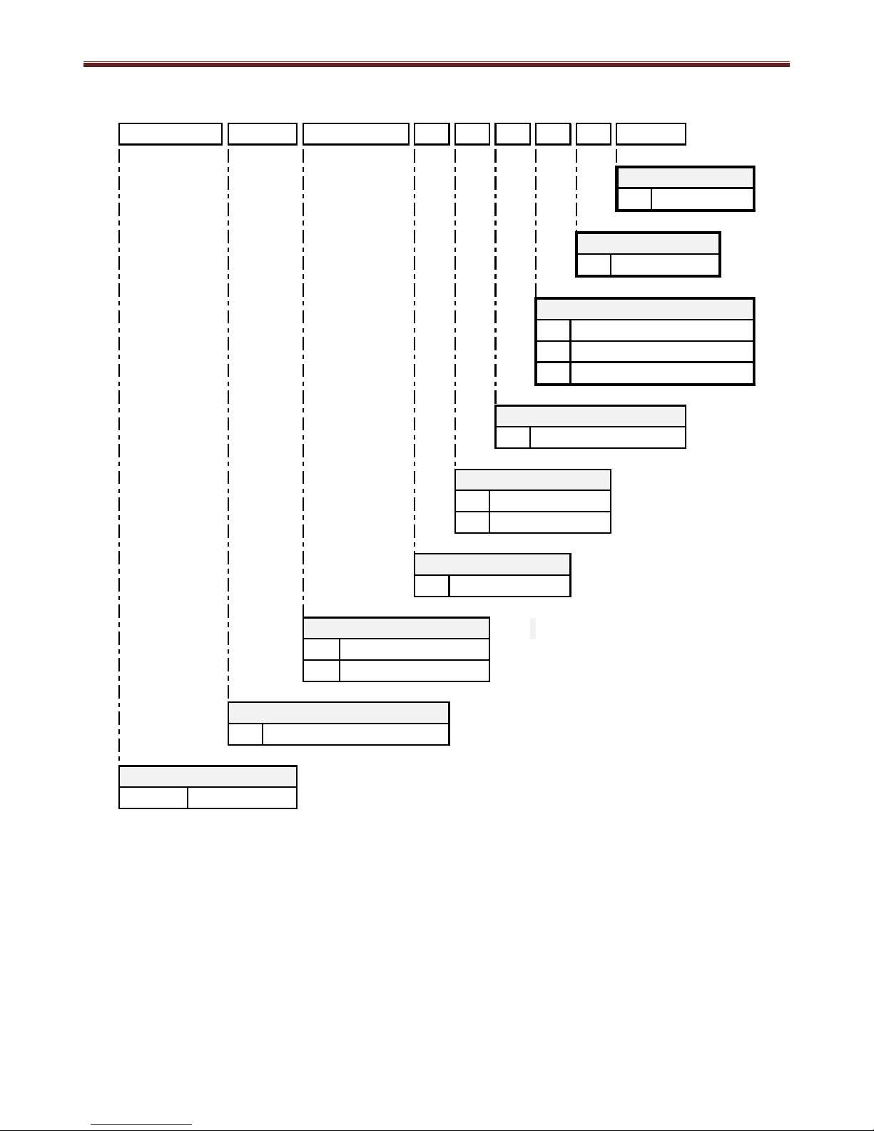
Model naming convention:
H W S - G 1 9 0 1 C N M R - E
E
R
M
R
X
N
C
E
1
190
260
G
Europe
Area
Tank Type
Factory
HWS
Thermodynamic HWS
Model Type
A2W
TCEU
Standard Tank (45°)
180° variant tank
Deluxe PCB
Type
Coil Type
Coil
Extra coil
190l Capacity
260l Capacity
Enamelled Steel
Tank Material
Series Number
Series 1
Water Tank Capacity
Page 3

Domestic Hot Water Heat Pump Service Manual
2
Contents
1.0
Safety precautions . . . . . . . . . . . . . . . . . . . . . . . . . . . . . . . . . . . . . . . . . . . . . . . . . . . . . . . . . . . . . . . . . .
4
2.0
Specifications. . . . . . . . . . . . . . . . . . . . . . . . . . . . . . . . . . . . . . . . . . . . . . . . . . . . . . . . . . . . . . . . . . . . . .
6
3.0
DHW-HP Drawings. . . . . . . . . . . . . . . . . . . . . . . . . . . . . . . . . . . . . . . . . . . . . . . . . . . . . . . . . . . . . . . . . .
7
4.0
Wiring Diagram. . . . . . . . . . . . . . . . . . . . . . . . . . . . . . . . . . . . . . . . . . . . . . . . . . . . . . . . . . . . . . . . . . . . .
4.1 PC Board and connections. . . . . . . . . . . . . . . . . . . . . . . . . . . . . . . . . . . . . . . . . . . . . . . . . . . . . . .
9 4.2 Schematic . . . . . . . . . . . . . . . . . . . . . . . . . . . . . . . . . . . . . . . . . . . . . . . . . . . . . . . . . . . . . . . . . . . .
10
5.0
Key electric component rating . . . . . . . . . . . . . . . . . . . . . . . . . . . . . . . . . . . . . . . . . . . . . . . . . . . . . . . .
11
6.0
Refrigerant cycle / water system diagram . . . . . . . . . . . . . . . . . . . . . . . . . . . . . . . . . . . . . . . . . . . . . . .
6.1 Refrigeration cycle system diagram . . . . . . . . . . . . . . . . . . . . . . . . . . . . . . . . . . . . . . . . . . . . . . . .
12
6.2 Water system diagram . . . . . . . . . . . . . . . . . . . . . . . . . . . . . . . . . . . . . . . . . . . . . . . . . . . . . . . . .
12
7.0
Operational description . . . . . . . . . . . . . . . . . . . . . . . . . . . . . . . . . . . . . . . . . . . . . . . . . . . . . . . . . . . . .
7.1 P1 AUTO mode . . . . . . . . . . . . . . . . . . . . . . . . . . . . . . . . . . . . . . . . . . . . . . . . . . . . . . . . . . . . . . .
15
7.2 P2 ECO mode. . . . . . . . . . . . . . . . . . . . . . . . . . . . . . . . . . . . . . . . . . . . . . . . . . . . . . . . . . . . . . . . .
16 7.3 P3 BOOST mode . . . . . . . . . . . . . . . . . . . . . . . . . . . . . . . . . . . . . . . . . . . . . . . . . . . . . . . . . . . . .
17
7.4 P4 BACKUP mode . . . . . . . . . . . . . . . . . . . . . . . . . . . . . . . . . . . . . . . . . . . . . . . . . . . . . . . . . . . . .
18
7.5 P5 SILENT mode . . . . . . . . . . . . . . . . . . . . . . . . . . . . . . . . . . . . . . . . . . . . . . . . . . . . . . . . . . . . . .
19
7.6 P6 HOLIDAY mode . . . . . . . . . . . . . . . . . . . . . . . . . . . . . . . . . . . . . . . . . . . . . . . . . . . . . . . . . . . .
19
7.7 B4 Hot on time . . . . . . . . . . . . . . . . . . . . . . . . . . . . . . . . . . . . . . . . . . . . . . . . . . . . . . . . . . . . . . . .
20 7.8 B3 Low tariff . . . . . . . . . . . . . . . . . . . . . . . . . . . . . . . . . . . . . . . . . . . . . . . . . . . . . . . . . . . . . . . . . .
20
7.9 B1 Ventilation. . . . . . . . . . . . . . . . . . . . . . . . . . . . . . . . . . . . . . . . . . . . . . . . . . . . . . . . . . . . . . . . .
21
7.10 B5 Photovoltaic . . . . . . . . . . . . . . . . . . . . . . . . . . . . . . . . . . . . . . . . . . . . . . . . . . . . . . . . . . . . . . . .
22
7.10.1 PV ECO operation in AUTO mode . . . . . . . . . . . . . . . . . . . . . . . . . . . . . . . . . . . . . . . . . . .
25
7.10.2 PV ECO operation in BOOST mode . . . . . . . . . . . . . . . . . . . . . . . . . . . . . . . . . . . . . . . . .
26
7.10.3 PV Storage operation in BOOST mode . . . . . . . . . . . . . . . . . . . . . . . . . . . . . . . . . . . . . .
27 7.11 D26 Extra function . . . . . . . . . . . . . . . . . . . . . . . . . . . . . . . . . . . . . . . . . . . . . . . . . . . . . . . . . . . . .
28
7.11.1 B6 Solar . . . . . . . . . . . . . . . . . . . . . . . . . . . . . . . . . . . . . . . . . . . . . . . . . . . . . . . . . . . . . . .
28
7.11.2 B7 Floor / B8 Floor T . . . . . . . . . . . . . . . . . . . . . . . . . . . . . . . . . . . . . . . . . . . . . . . . . . . . .
29
7.11.3 B9 Cooling / Cooling T . . . . . . . . . . . . . . . . . . . . . . . . . . . . . . . . . . . . . . . . . . . . . . . . . . . .
30
7.12 D27 SG Ready . . . . . . . . . . . . . . . . . . . . . . . . . . . . . . . . . . . . . . . . . . . . . . . . . . . . . . . . . . . . . . . .
31
7.13 D29 External control . . . . . . . . . . . . . . . . . . . . . . . . . . . . . . . . . . . . . . . . . . . . . . . . . . . . . . . . . . . .
33 7.14 Defrost operation. . . . . . . . . . . . . . . . . . . . . . . . . . . . . . . . . . . . . . . . . . . . . . . . . . . . . . . . . . . . . . .
35
7.15 Legionella operation . . . . . . . . . . . . . . . . . . . . . . . . . . . . . . . . . . . . . . . . . . . . . . . . . . . . . . . . . . . .
36
8.0
Modbus . . . . . . . . . . . . . . . . . . . . . . . . . . . . . . . . . . . . . . . . . . . . . . . . . . . . . . . . . . . . . . . . . . . . . . . . . .
38
8.1 Monitoring functions . . . . . . . . . . . . . . . . . . . . . . . . . . . . . . . . . . . . . . . . . . . . . . . . . . . . . . . . . . . .
40
8.2 Read & write functions . . . . . . . . . . . . . . . . . . . . . . . . . . . . . . . . . . . . . . . . . . . . . . . . . . . . . . . . . .
41
9.0
Method of defect analysis . . . . . . . . . . . . . . . . . . . . . . . . . . . . . . . . . . . . . . . . . . . . . . . . . . . . . . . . . . . .
9.1 Matters to be confirmed first . . . . . . . . . . . . . . . . . . . . . . . . . . . . . . . . . . . . . . . . . . . . . . . . . . . . . .
44
9.1.1 Check the power supply voltage . . . . . . . . . . . . . . . . . . . . . . . . . . . . . . . . . . . . . . . . . . . .
44
9.1.2 Check the cold water supply . . . . . . . . . . . . . . . . . . . . . . . . . . . . . . . . . . . . . . . . . . . . . . .
44
9.2 In the event of error – how to operate BACK-UP mode . . . . . . . . . . . . . . . . . . . . . . . . . . . . . . . . .
45
9.3 Error codes . . . . . . . . . . . . . . . . . . . . . . . . . . . . . . . . . . . . . . . . . . . . . . . . . . . . . . . . . . . . . . . . . . .
45
9.4 Error code analysis . . . . . . . . . . . . . . . . . . . . . . . . . . . . . . . . . . . . . . . . . . . . . . . . . . . . . . . . . . . . .
45 9.4.1 Er1 ~ Er5 – Temperature sensor error analysis . . . . . . . . . . . . . . . . . . . . . . . . . . . . . . . . .
46
9.4.2 Er HP – High pressure switch error analysis . . . . . . . . . . . . . . . . . . . . . . . . . . . . . . . . . . .
46
9.4.3 Er Evap – Evaporator temperature error analysis . . . . . . . . . . . . . . . . . . . . . . . . . . . . . . .
47
9.4.4 Er H Evap – High evaporator temperature error analysis . . . . . . . . . . . . . . . . . . . . . . . . .
47
9.4.5 Er C Evap – Low evaporator temperature error analysis . . . . . . . . . . . . . . . . . . . . . . . . .
48
9.4.6 Er Filter – Change filter error analysis . . . . . . . . . . . . . . . . . . . . . . . . . . . . . . . . . . . . . . . .
48 9.5 Resetting of error code & BACK-UP mode . . . . . . . . . . . . . . . . . . . . . . . . . . . . . . . . . . . . . . . . . . .
48
10.0
DHWHP Settings
10.1 Home view . . . . . . . . . . . . . . . . . . . . . . . . . . . . . . . . . . . . . . . . . . . . . . . . . . . . . . . . . . . . . . . . . .
49
10.1.1 Information menu . . . . . . . . . . . . . . . . . . . . . . . . . . . . . . . . . . . . . . . . . . . . . . . . . . . . . . .
50
10.1.2 Mode of operation . . . . . . . . . . . . . . . . . . . . . . . . . . . . . . . . . . . . . . . . . . . . . . . . . . . . . .
51
10.1.3 Temperatures . . . . . . . . . . . . . . . . . . . . . . . . . . . . . . . . . . . . . . . . . . . . . . . . . . . . . . . . . .
52
10.1.4 Functions . . . . . . . . . . . . . . . . . . . . . . . . . . . . . . . . . . . . . . . . . . . . . . . . . . . . . . . . . . . . .
53 10.1.5 General . . . . . . . . . . . . . . . . . . . . . . . . . . . . . . . . . . . . . . . . . . . . . . . . . . . . . . . . . . . . . . .
54
10.1.6 Installer . . . . . . . . . . . . . . . . . . . . . . . . . . . . . . . . . . . . . . . . . . . . . . . . . . . . . . . . . . . . . . .
55
11.0
Periodic inspection items . . . . . . . . . . . . . . . . . . . . . . . . . . . . . . . . . . . . . . . . . . . . . . . . . . . . . . . . . . .
58
11.1 Environmental requirements . . . . . . . . . . . . . . . . . . . . . . . . . . . . . . . . . . . . . . . . . . . . . . . . . . . . . .
58
11.2 Heating system and fan . . . . . . . . . . . . . . . . . . . . . . . . . . . . . . . . . . . . . . . . . . . . . . . . . . . . . . . . .
58 11.3 Condensation and condensate drain . . . . . . . . . . . . . . . . . . . . . . . . . . . . . . . . . . . . . . . . . . . . . . .
58
Page 4

Domestic Hot Water Heat Pump Service Manual
3
11.4 Water circulation and tank . . . . . . . . . . . . . . . . . . . . . . . . . . . . . . . . . . . . . . . . . . . . . . . . . . . . . . . .
11.4.1 Pressure relief valve . . . . . . . . . . . . . . . . . . . . . . . . . . . . . . . . . . . . . . . . . . . . . . . . . . . . .
58
11.4.2 Anode . . . . . . . . . . . . . . . . . . . . . . . . . . . . . . . . . . . . . . . . . . . . . . . . . . . . . . . . . . . . . . . .
59
12.0
Part exploded view, part list . . . . . . . . . . . . . . . . . . . . . . . . . . . . . . . . . . . . . . . . . . . . . . . . . . . . . . . . . .
60
13.0
Main components replacement. . . . . . . . . . . . . . . . . . . . . . . . . . . . . . . . . . . . . . . . . . . . . . . . . . . . . . . .
13.1 Open & remove the front panel . . . . . . . . . . . . . . . . . . . . . . . . . . . . . . . . . . . . . . . . . . . . . . . . . . . .
61
13.2 Remove the top shell & top cover . . . . . . . . . . . . . . . . . . . . . . . . . . . . . . . . . . . . . . . . . . . . . . . . .
62
13.3 Remove the evaporator housing top . . . . . . . . . . . . . . . . . . . . . . . . . . . . . . . . . . . . . . . . . . . . . . . .
63
13.4 Replace the heating element . . . . . . . . . . . . . . . . . . . . . . . . . . . . . . . . . . . . . . . . . . . . . . . . . . . . .
63
13.5 Replace the safety breakers . . . . . . . . . . . . . . . . . . . . . . . . . . . . . . . . . . . . . . . . . . . . . . . . . . . . . .
64
13.6 Replace the anode . . . . . . . . . . . . . . . . . . . . . . . . . . . . . . . . . . . . . . . . . . . . . . . . . . . . . . . . . . . . .
64 13.7 Replace the solenoid valve, coil . . . . . . . . . . . . . . . . . . . . . . . . . . . . . . . . . . . . . . . . . . . . . . . . . . .
65
13.8 Replace the fan kit . . . . . . . . . . . . . . . . . . . . . . . . . . . . . . . . . . . . . . . . . . . . . . . . . . . . . . . . . . . . .
66
13.9 Replace the BT1 Sensor . . . . . . . . . . . . . . . . . . . . . . . . . . . . . . . . . . . . . . . . . . . . . . . . . . . . . . . .
66
13.10 Replace the BT2 Sensor . . . . . . . . . . . . . . . . . . . . . . . . . . . . . . . . . . . . . . . . . . . . . . . . . . . . . . . .
67
13.11 Replace the BT3 Sensor . . . . . . . . . . . . . . . . . . . . . . . . . . . . . . . . . . . . . . . . . . . . . . . . . . . . . . . .
67
13.12 Replace the BT4 Sensor . . . . . . . . . . . . . . . . . . . . . . . . . . . . . . . . . . . . . . . . . . . . . . . . . . . . . . . .
68 13.13 Replace the Compressor . . . . . . . . . . . . . . . . . . . . . . . . . . . . . . . . . . . . . . . . . . . . . . . . . . . . . . . .
69
13.14 Replace the Tube kit . . . . . . . . . . . . . . . . . . . . . . . . . . . . . . . . . . . . . . . . . . . . . . . . . . . . . . . . . . . .
70
13.15 Replace the PCB Board standard & deluxe . . . . . . . . . . . . . . . . . . . . . . . . . . . . . . . . . . . . . . . . . .
71
13.16 Replace the display & frame . . . . . . . . . . . . . . . . . . . . . . . . . . . . . . . . . . . . . . . . . . . . . . . . . . . . .
71
Page 5

Domestic Hot Water Heat Pump Service Manual
4
1.0 Safety precautions
The product shall be installed, commissioned, repaired only by qualified technicians. Incorrect installation can
result in damage to property and/or injuries to people and animals.
The unit shall be disconnected from the power supply when the cover is off.
The unit shall not be used by children or people with limited physical or mental capacity.
Children should be supervised to ensure that they do not play with the appliance.
Cleaning and maintenance shall not be made by children without supervision.
Do not place flammable materials in contact or close to the unit.
The water system and the air system should be installed as stated in the manual.
When in service, the unit should not be placed in sub-zero temperature areas.
When not in service, the unit can be placed in sub-zero temperature areas, but all the water in the tank or in the
condensate drain should be removed.
Hot water can cause serious burns if directly connected to the taps. The installation of a mixing valve is suggested.
The unit should be used only for its specified use. The manufacturer is not liable for any damages due to failure to
observe this manual.
Take all the possible precautions to avoid incidents.
The product contains HFC-R134a
The electrical supply, for the domestic hot water heat pump, must be protected by an earth leakage breaker and an
overcurrent protection device (fuse or circuit breaker).
Failure to comply with this precaution may result in electric shock or fire
This unit must be connected to the main power supply using a circuit breaker or switch with a contact separation of
at least 3mm
Introduction
The aim of this manual is to give information, instructions and warnings on the domestic hot water heat pump. The
manual is to be used by service engineers, since it contains important safety, diagnosis and operational indications.
The manual is a part of the domestic hot water heat pump and it is to be conserved with care, since it contains
important installation and maintenance instructions that can be useful to assure a long life time and an efficient
operation.
About the product
The product is a domestic hot water heat pump (DHWHP) that has been designed according to EU directives. The
product is intended for hot water production for domestic use or for similar applications. The unit has been designed to
be ready for installation.
General
The domestic hot water heat pump is composed of a water tank, a refrigerant circuit, a cabinet and a display
connected to a control board. The main scope of the appliance is to heat water stored in a tank.
Operation
The unit is programmed to start heating the water inside the tank when its temperature falls below a predetermined
level, BBT3 (T Tank Top) is 5K<SP. The unit stops when the water temperature reaches a set point (SP) that can be
regulated by the user. In general, the appliance is designed to produce enough hot water to cover the need of a
household of 4 persons or more.
There are two ways in which the DHW-HP can heat the water:
1) Heat pump operation
In the operation with heat pump, a heating cycle utilizes the operation of a compressor and the extraction of the
heat from the air to heat the water in the tank. This is the standard way used to heat the domestic hot water, since
it leads to lower electricity consumption, hence also lower running costs.
2) Electric heater operation
The water is heated using an electric heater. An electric resistance is powered to heat the water in a safe, fast and
flexible way. However, using the electrical heater can become an expensive way to produce hot water. This
operation should be used as a back-up or as integration of the standard operation.
Page 6
Domestic Hot Water Heat Pump Service Manual
5
The electric heater is activated in case of:
Failure of the heat pump operation, this requires an override command from the end user to be confirmed
Too high or too low air temperature
The quantity of hot water produced is not enough.
Note: The amount of water heated by the electric heater is at a reduced volume; see the performance data for
these values.
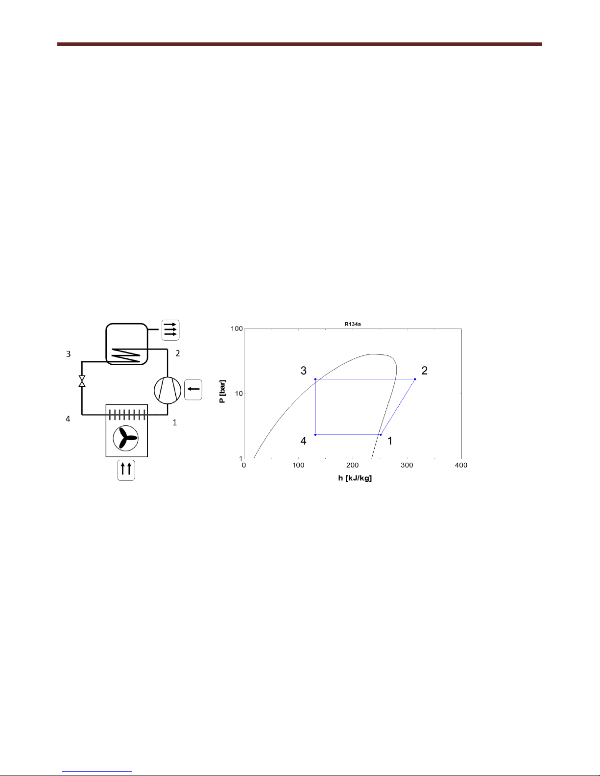
Heating circuit
As depicted in the figure below, the heat pump cycle can be divided in four main processes: compression (1-2),
condensation 2-3), expansion (3-4) and evaporation (4-1) described below.
At the suction of the compressor (1) the superheated gas refrigerant enters the compressor at a low pressure.
In the compressor, the gas is compressed to a higher pressure and temperature level (2).
The gas is first de-superheated and condensed in the condenser, exchanging heat with the water stored in the
tank.
The refrigerant exits the condenser in a subcooled, liquid form (3)
Through the thermostatic expansion valve the pressure of the refrigerant is lowered to allow its evaporation at a
lower temperature (4)
The refrigerant is evaporated in the fin-coil heat exchanger that uses forced air as a heat source (1)
The process goes on until the power supply to the compressor is stopped.
Note: the extensive use of the electric heater leads to a higher electricity consumption and it may lead to high
electricity bills. The operation with the heat pump normally consumes more than 3 times less electricity than the
operation with electric heater. The energy released to the condenser (2-3) is, in fact, the sum between the free energy
extracted from the air in the evaporator (1-4) and the energy supplied to the compressor (2-1). On average, the energy
absorbed by the evaporator is more than double of the energy used to run the compressor.
Safety instructions – Heating circuit
Only skilled and trained technicians shall carry out repair and service of the heat pump circuit.
Before opening the heating circuit, discharge the refrigerant to a level that allows safe working conditions.
The refrigerant can be toxic if inhaled or if in high concentrations.
Special attention should be given if the work is carried out with an open flame.
Page 7
Domestic Hot Water Heat Pump Service Manual
6
2.0 Specifications
Physical data
Domestic Hot Water Heat Pump
HWS-G1901CN*R-E
HWS-G2601CN*R-E
HWS-G1901ENXR-E
HWS-G2601ENXR-E
Dimensions (Height x Diameter)
mm
1600x620
1960x620
1600x620
1960x620
Weight (dry / wet)
kg
91 / 281
106/356
107/297
126/376
Nominal insulation thickness
mm
50
50
50
50
Refrigerant R134A
R134A
R134A
R134A
Refrigerant charge
kg
1.2
1.28
1.2
1.28
Refrigerant charge CO2 equivalent
ton
1.70
1.80
1.70
1.80
Water connections (cold & hot water)
inch
3/4
3/4
3/4
3/4
Water connections (entry angle)
deg.
45 / 180
45 / 180
45 / 180
45 / 180
Condensates water connections
mm
Ø19
Ø19
Ø19
Ø19
Max water side operating pressure
Mpa
0.6
0.6
0.6
0.6
Power supply
V-ph-Hz
230-1-50
230-1-50
230-1-50
230-1-50
Performance data
Domestic Hot Water Heat Pump
HWS-G1901CN*R-E
HWS-G2601CN*R-E
HWS-G1901ENXR-E
HWS-G2601ENXR-E
Energy Class - A+
A+
A+
A+
COP at Air7°C W10°C-52,9°C (EN16147)
-
3.57
3.69
3.57
3.69
Heat up time (A7°C W10°C-53,5°C)
hh:mm
06:27
09:12
06:27
09:12
COP at Air20°C W10°C-52,9°C (EN16147)
-
4.13
4.2
4.13
4.2
Heat up time (A20°C W10°C-53,5°C)
hh:mm
05:15
07:09
05:15
07:09
Cylinder volume
l
190
260
184
252
V40 volume (W52.9°C)
l
247
347
234
331
Maximum Qty of water by electric heater
only
l (%)
75 (40%)
130 (50%)
75 (40%)
130 (50%)
Maximum water temperature
°C
60
60
60
60
Corrosion protection
Magnesium anode
Magnesium anode
Magnesium anode
Magnesium anode
Heat pump operating range (min/max)
°C
-7 / +40
-7 / +40
-7 / +40
-7 / +40
Electrical heater Power
W
1500
1500
1500
1500
Maximum Power input
W
2185
2185
2185
2185
Auxiliary Power input (Paux)
W
1.61
1.61
1.61
1.61
Standby Power input (Pes)
W
17
20
17
20
Sound power level - Air7°C W10°C-52,9°C
(EN16147)
dB(A)
49
49
49
49
Sound power level - Air20°C W10°C-52,9°C
(EN16147)
dB(A)
55.6
55.6
55.6
55.6
Airflow rate nominal (min - max)
m3/h
450 (0 - 800)
450 (0 - 800)
450 (0 - 800)
450 (0 - 800)
Maximum fan power
W
85
85
85
85
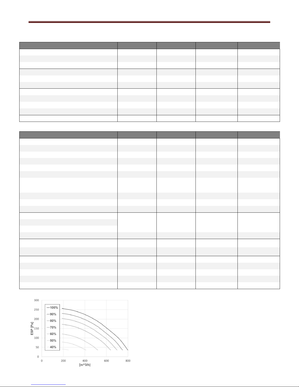
Maximum external static pressure
Pa
200
200
200
200
Air duct connections
mm
Ø160
+Ø160
Ø160
Ø160
Minimum room volume (non-ducted unit)
m3
60
60
60
60
Fan Curve
The graph shows the external static pressure vs airflow
at different fan speeds.
In order to assure an efficient operation, it is suggested
to keep the external pressure drops below 200 Pa.
Page 8
Domestic Hot Water Heat Pump Service Manual
7
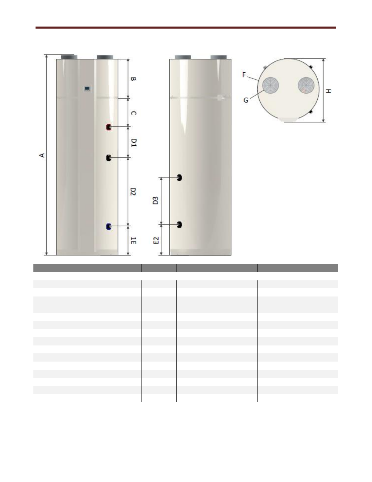
3.0 DHW-HP drawing
Parameter
Unit
HWS-G1901***R-E
HWS-G2601***R-E
Dimensional Data
A – Height
mm
1610
1960
B
mm
385
385
C
mm
280
280
D1
mm
180
300
D2
mm
435
670
D3
mm
375
375
E1
mm
285
285
E2
mm
305
305
F – Diameter
mm
603
603
G – Diameter
mm
160
160
H – Max Diameter
mm
620
620
Height required for installation
mm
1700
2040
Standard DHW-HP weight dry/wet
kg
94 / 284
100 / 350
Additional coil DHW-HP weight dry/wet
Kg
100/300
120/370
Nominal insulation thickness
mm
50
50
Page 9
Domestic Hot Water Heat Pump Service Manual
8
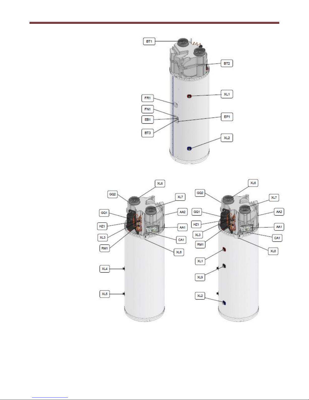
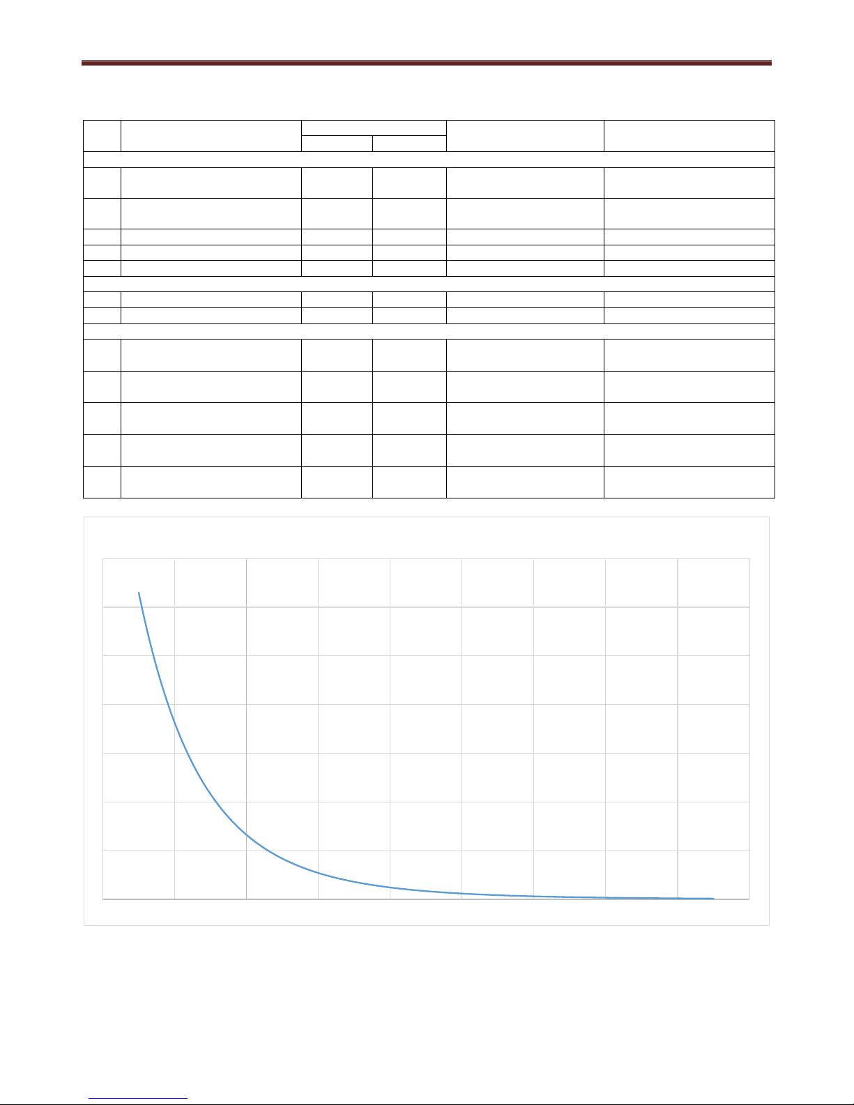
Refrigerant circuit
GQ1: Compressor
GQ2: Fan
RM1: Check valve
EP1: Condenser
EP2: Evaporator
HZ1: Filter drier
QN1: Solenoid valve
QN2: Thermostatic expansion valve
XL3: Service valve
Water circuit
XL1: Water outlet
XL2: Water inlet
XL4*: Coil top
XL5*: Coil bottom
XL6: Air outlet
XL7: Air inlet
XL8: Condensate outlet
XL9*: Hot water circulation
EP3*: Coil
EB1: Electric heater
FR1: Anode
FN1: Thermal protection
The items with * are optional.
Figure 4 – Design of the heating circuit and the main components
Sensors
BBT1: Air inlet temperature
BBT2: Evaporator temperature
BBT3: Tank water temperature
BBT4*: Additional temperature
BBT5*: Additional temperature
(not included)
BP1: Pressostat
Electric components
AA1: Main printed circuit board
AA2: Display circuit board
WF1: Modbus port
GC1*: Solar 0-3V/10V
QA1*: SG-ready port
GP1*: Additional supply to pump
or damper
The items with * are optional.
Figure 5 – Design of tank, condenser and related components
Nomenclature according to standard
IEC 81346-1 and 81346-2.
Page 10
Domestic Hot Water Heat Pump Service Manual
9
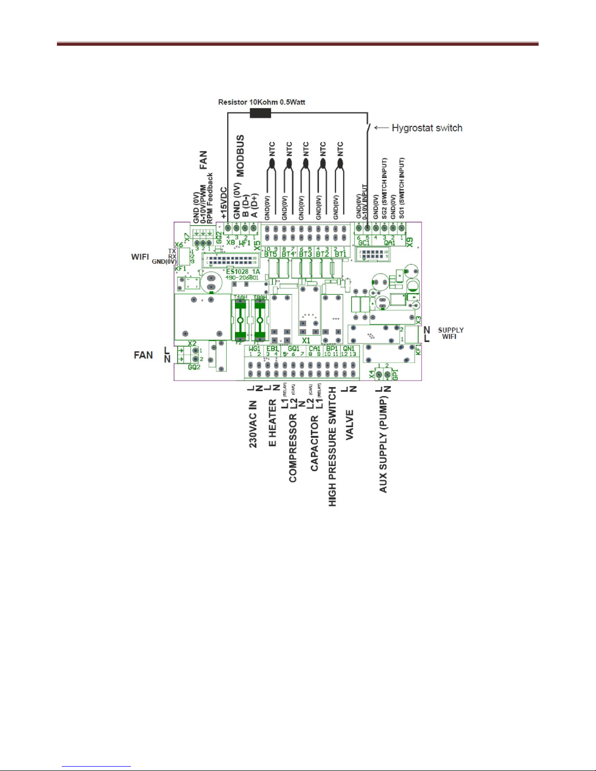
4.0 Wiring diagram
4.1 PC Board and connections
Page 11
Domestic Hot Water Heat Pump Service Manual
10
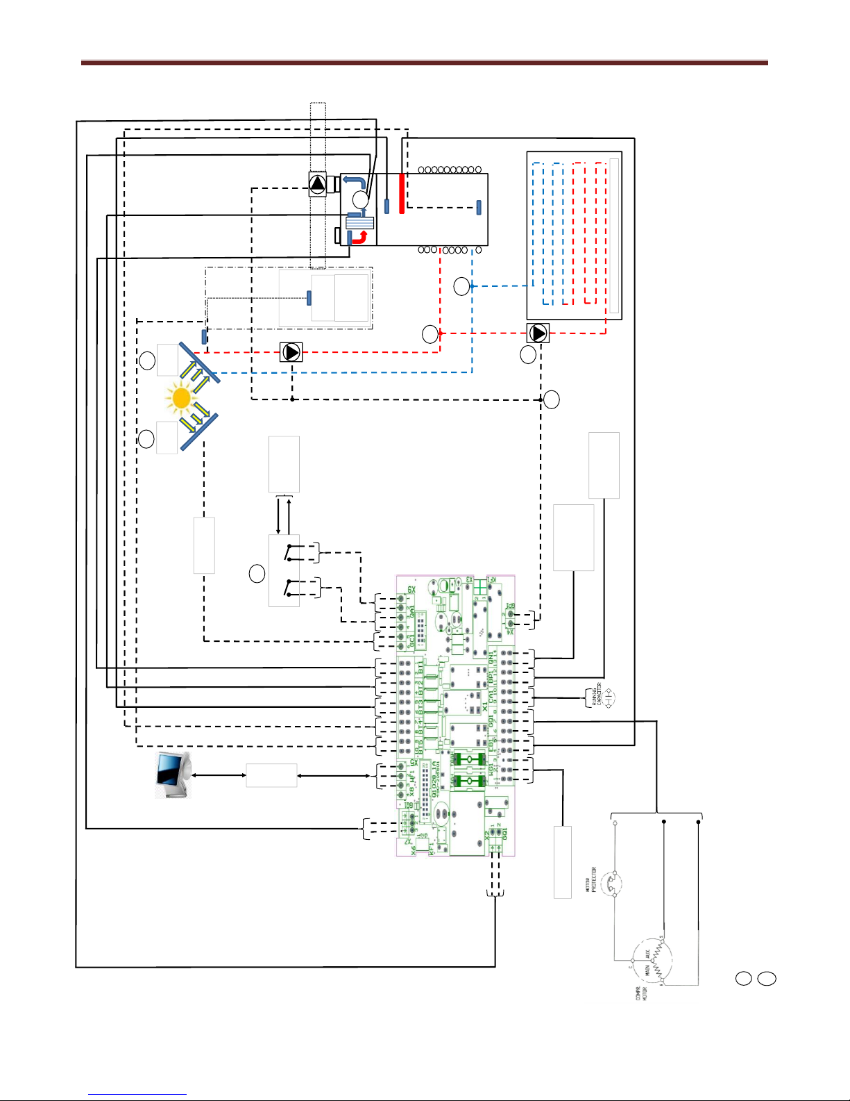
4.2 Schematic
= Schematic shows all available options connected to the DHWHP PCB. In reality it is not possible to connect the solar thermal panel / circuit at the same time as the underfloor heating circuit.
It is only possible to connect one of these options to the DHWHP at any one time
= Schematic shows all available options connected to the DHWHP PCB. These options are only available with the deluxe model DHWHP units only.
BLU
B (D-)
L
N
L
N
0V
0V
L
L
0V
0~10V
Input
BT3
EB1
0V
0V
0V
FM
BT2
BT1
0V
0V
L
N
PE
230VAC ~ 50Hz
0V
A (D+)
0V BLU
0~10V PWM
YEL
High pressure switch.
Compressor STOP when
Pd ≥ 2.0MPa
Solenoid valve.
Solenoid ON for 2 min
before compressor
starts and during
system defrost
BRN
BLK
N
BLU
BLK
BRN
BRN
BLU
#1
Energy Meter
Communication to
/ from power grid
SG2
SG1
0V
0V
#2
#2
Modbus
communication
Inverter
#2
Solar
PV
BT4
#1#1#2
BT5
Under floor
heating
or
Cooling
Room
temperature
Under floor heating circuit
#2
Solar
Thermal
BT5
#1
Page 12
Domestic Hot Water Heat Pump Service Manual
11
5.0 Key electric component rating
No.
Component Name
Model
Type
Rating
Standard
Deluxe
Refrigeration
1
Highly compressor
ο
ο
WHP01900BUV-H8JU
Winding resistance
4.82/6.22Ω (at 20°C)
2
Case thermostat
ο
ο
B110-160-241E
Contact open: 160±10°C
Contact Close: 70±10°C
3
Fan motor
ο
ο
R3G220-RC05-17
230V / 0.7A / 50-60Hz
4
Solenoid
ο
ο
FDF2.5A 08
230V / 50-60Hz
5
High pressure switch
ο
ο
UL1015 18AWG
Open press: 20±1 bar
Electrical
6
Heating element
ο
ο
Kanthal D or 0Cr23AI5
230V / 1500W
7
Heater thermostat (x2)
ο
ο
El Matik KB
80±3°C
Sensors
8
BBT1 Motron
ο
ο
AHC3.782.244-65A
(L=400mm)
R25=22.00k +/-1%, -30
to +105°C
9
BBT2 Motron
ο
ο
AHC3.782.244-65B
(L=900mm)
R25=22.00k +/-1%, -30
to +105°C
10
BBT3 Motron
ο
ο
AHC3.782.244-65C
(L=2200mm)
R25=22.00k +/-1%, -30
to +105°C
11
BBT4 Motron
-
ο
AHC3.782.244-65D
(L=2700mm)
R25=22.00k +/-1%, -30
to +105°C
12
BBT5 Motron
-
ο
AHC3.782.244-65D
(L=2700mm)
R25=22.00k +/-1%, -30
to +105°C
0
50000
100000
150000
200000
250000
300000
350000
-40 -20 0 20 40 60 80 100 120 140
R-ntc [ohm] vs Temperature [C]
Page 13
Domestic Hot Water Heat Pump Service Manual
12
6.0 Refrigerant cycle / water system diagram
6.1 Refrigerant cycle
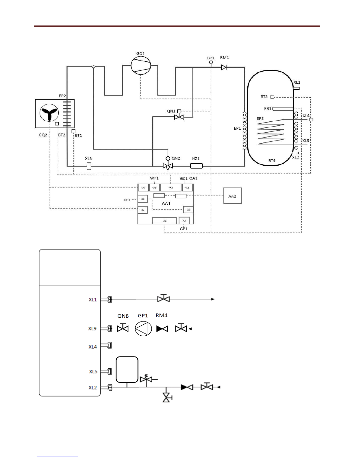
6.2 Water system cycle
XL1: Water outlet pipe connection
XL2: Water inlet pipe connection
XL4: Coil top*
XL5: Coil bottom*
XL9: Water circulation connection*
QN3: Shut-off valve water outlet
QN4: Shut-off valve water inlet
QN5: Drain valve
QN6: Safety valve**
QN7: Expansion tank**
QN8: Shut-off valve pump inlet*
QN9: Shut-off valve pump outlet*
RM3: Check valve
RM4: Check valve water circulation*
GP1: Water circulation pump*
* Optional additional coil
** Safety equipment required for the
installation to be locally sourced (i.e.
safety group, expansion vessel)
QN7
QN5
QN6
QN3
RM3 QN4
QN3
QN9
Page 14
Domestic Hot Water Heat Pump Service Manual
13
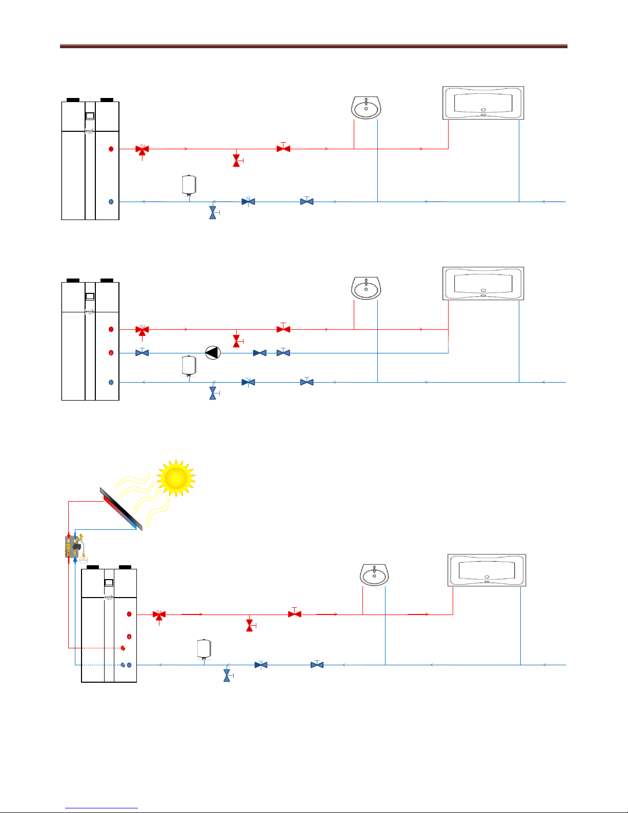
Example of a standard circuit with the DHW-HP installation
Example of a circulation circuit with the DHW-HP installation
Example of solar thermal circuit with the DHW-HP installation
2 1
8 9 11
10
6
7 4 3
5
TOSHIBA
2
1
8 9
11
10
16
15
14
13 12
6
7 4
3
5
TOSHIBA
17
18
2
1
8 9
11
10
16
6
7 4
3
5
TOSHIBA
19
20
Page 15
Domestic Hot Water Heat Pump Service Manual
14
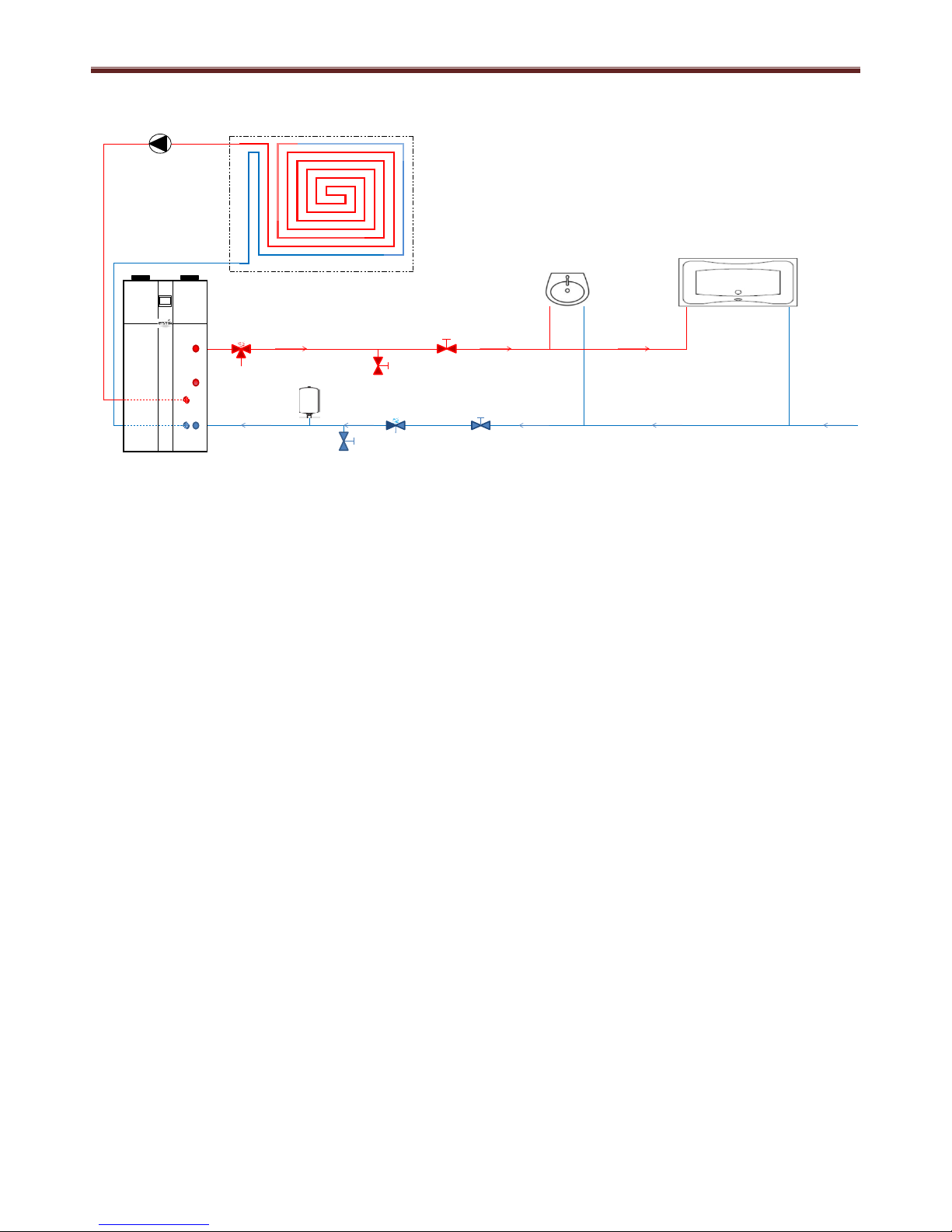
Example of underfloor heating circuit with the DHW-HP installation
21 22
2
1
8 9
11
10
16
6
7 4
3
5
TOSHIBA
19
20
1
Bath
12
Isolation valve return flow
2
Sink
13
Check valve
3
Cold water supply shut off valve
14
Circulation pump
4
Safety group
15
Isolation valve circulation
5
Cold water supply drain valve
16
Water circulation connection point
6
Expansion vessel
17
Solar thermal collectors
7
Cold water supply pipe connection
18
Pump & expansion vessel
8
Hot water outlet pipe connection
19
Extra coil inlet
9
Temperature & pressure relief valve (6 bar / 90°C)
20
Extra coil outlet
10
Hot water supply drain valve
21
Circulation pump
11
Hot water supply shut off valve
22
Underfloor heating circuit
Page 16
Domestic Hot Water Heat Pump Service Manual
15
7.0 Operational description
7.1 P1 AUTO mode
This is the standard operation mode for the domestic hot water heat pump.
The temperature is set from main menu, by pressing the ’OK’ button.
Select ‘A Temperatures’ and then A1 AUTO to set temperature for auto mode, default set point is
53°C.
As long as the air inlet temperature, BT1, is within the specified temperature range, default -7 ~
+40°C then the DHW-HP will operate normally, if BT1 temperature is outside of its operating range
then the water will be heated using the electrical heater only.
Code
Set Point
Name
Description
Range
Factory
setting
A1
T AUTO
The temperature level at which the DHW-HP
heats the water when AUTO mode is selected.
50 ~ 60
53.5
The DHW-HP will then heat the water to set point using the heat pump only.
If the water temperature, BT3, reduces by 5°C then the DHW-HP will start to reheat the water
temperature back to set point.
DHW-HP starts operation on selection of AUTO mode, T AUTO <SP -5k
DHW-HP stops when BT3 = T AUTO SP (53.5°C factory setting)
DHW-HP restarts when T AUTO = SP -5k
DHW-HP stops when BT3 = T AUTO SP (53.5°C factory setting)
0
10
20
30
40
50
60
70
80
00:00:00
00:07:40
00:15:20
00:23:00
00:30:40
00:38:20
00:46:00
00:53:40
01:01:20
01:09:00
01:16:40
01:24:20
01:32:00
01:39:40
01:47:20
01:55:00
02:02:40
02:10:20
02:18:00
02:25:40
02:33:20
02:41:00
02:48:40
02:56:20
03:04:00
03:11:40
03:19:20
03:27:00
03:34:40
03:42:20
03:50:00
03:57:40
04:05:20
04:13:00
04:20:40
04:28:20
04:36:00
04:43:40
04:51:20
04:59:00
05:06:40
05:14:20
05:22:00
05:29:40
05:37:20
05:45:00
05:52:40
06:00:20
06:08:00
06:15:40
06:23:20
06:31:00
06:38:40
06:46:20
T1 T air in T3 T water top
HP_OnTemp HP_OffTemp
R3 Fan R4 Comp
Fan Off
Fan On
Comp Off
Comp On
Page 17
Domestic Hot Water Heat Pump Service Manual
16
7.2 P2 ECO mode
This is the standard operation mode for the domestic hot water heat pump.
The temperature is set from main menu, by pressing the ’OK’ button.
Select ‘A Temperatures’ and then A2 ECO to set temperature for eco mode, default set point is
50°C.
As long as the air inlet temperature, BT1, is within the specified temperature range, default -7 ~
+40°C then the DHW-HP will operate normally, if BT1 temperature is outside of its operating range
then the water will be heated using the electrical heater only.
Code
Set Point
Name
Description
Range
Factory
setting
A2
T ECO
The temperature level at which the DHW-HP
heats the water when ECO mode is selected.
50 ~ 55
50
The DHW-HP will then heat the water to set point using the heat pump only.
If the water temperature, BT3, reduces by 5°C then the DHW-HP will start to reheat the water
temperature back to set point.
DHW-HP starts operation on selection of ECO mode, T ECO <SP -5k
DHW-HP stops when BT3 = T ECO SP (50°C factory setting)
DHW-HP restarts when T ECO = SP -5k
DHW-HP stops when BT3 = T ECO SP (50°C factory setting)
0
10
20
30
40
50
60
70
80
00:00:00
00:07:40
00:15:20
00:23:00
00:30:40
00:38:20
00:46:00
00:53:40
01:01:20
01:09:00
01:16:40
01:24:20
01:32:00
01:39:40
01:47:20
01:55:00
02:02:40
02:10:20
02:18:00
02:25:40
02:33:20
02:41:00
02:48:40
02:56:20
03:04:00
03:11:40
03:19:20
03:27:00
03:34:40
03:42:20
03:50:00
03:57:40
04:05:20
04:13:00
04:20:40
04:28:20
04:36:00
04:43:40
04:51:20
04:59:00
05:06:40
05:14:20
05:22:00
05:29:40
05:37:20
05:45:00
05:52:40
06:00:20
06:08:00
06:15:40
06:23:20
06:31:00
06:38:40
06:46:20
T1 T air in T3 T water top
HP_OnTemp HP_OffTemp
R3 Fan R4 Comp
Fan Off
Fan On
Comp Off
Comp On
Page 18
Domestic Hot Water Heat Pump Service Manual
17
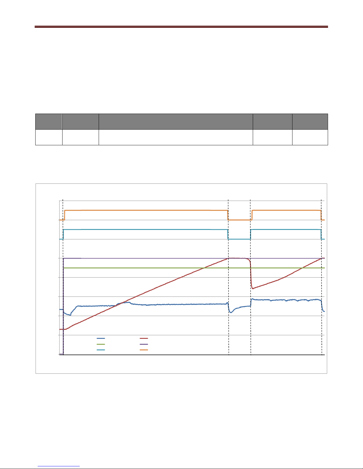
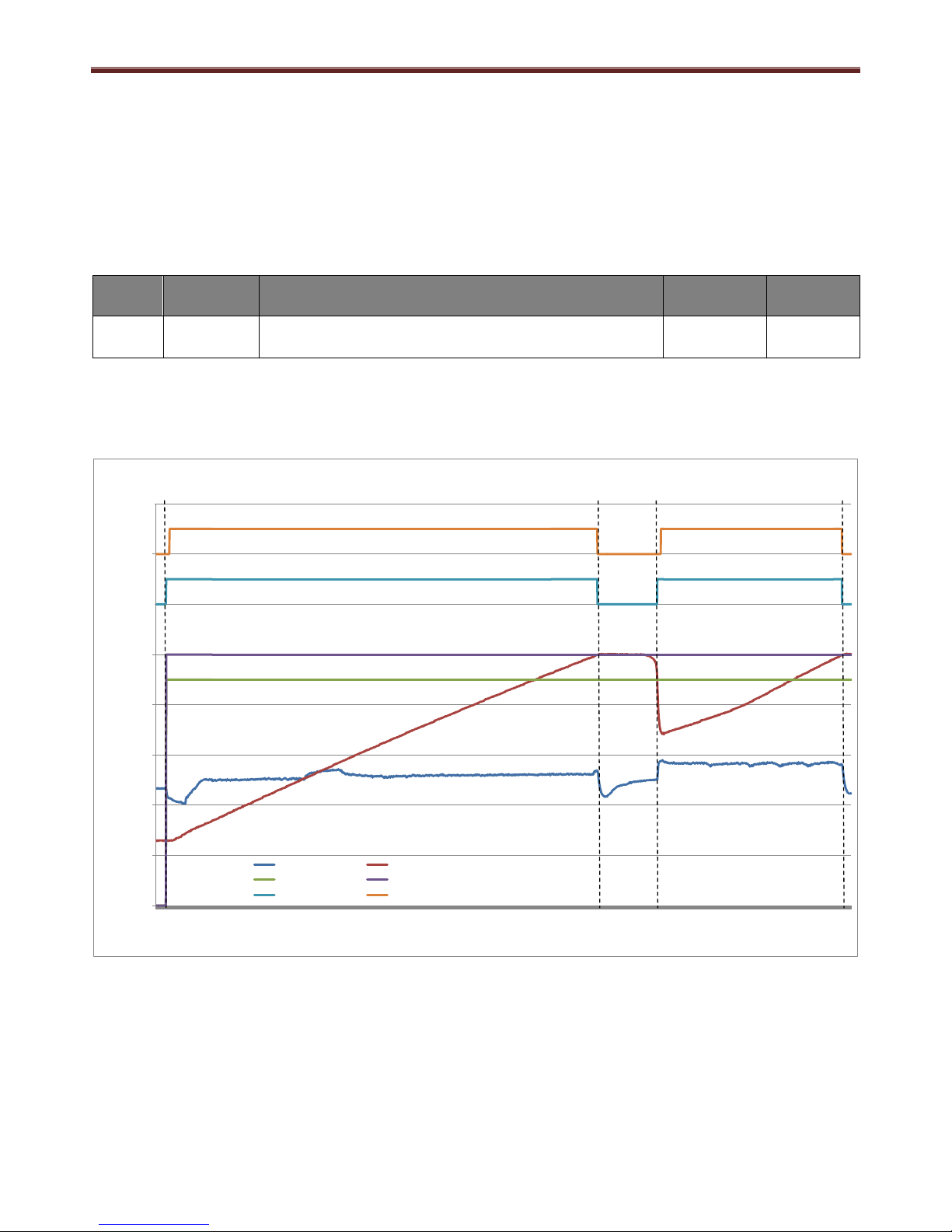
7.3 P3 BOOST mode
This is the standard operation mode for the domestic hot water heat pump.
The temperature is set from main menu, by pressing the ’OK’ button.
Select ‘A Temperatures’ and then A2 ECO to set temperature for eco mode, default set point is
50°C.
As long as the air inlet temperature, BT1, is within the specified temperature range, default -7 ~
+40°C then the DHW-HP will operate normally, if BT1 temperature is outside of its operating range
then the water will be heated using the electrical heater only.
Code
Set Point
Name
Description
Range
Factory
setting
A3
T BOOST
The temperature level at which the DHW-HP
heats the water when BOOST mode is selected.
50 ~ 65
55
The DHW-HP will then heat the water to set point using the heat pump and the electrical heater
together.
If A3 T BOOST temperature is set higher than D33 (Temp HP max – default 60°C) then the
remaining temperature above this set point is reached by electrical heater only operation
If the water temperature, BT3, reduces by 5°C then the EL heater will start to reheat the water
temperature back to set point.
The HP requires the BT3 temperature to reduce to 5°C below D33 (Temp HP Max SP)
In this case 8°C below BOOST mode temperature set point (A3 = 63°C).
NOTE: A3 T BOOST set to 63°C for illustration purposes.
NOTE: Volume of water heated by EL heater is only a percentage of the full water volume, as
follows: 190l = 75l (40%)
260l = 130l (50%)
0
10
20
30
40
50
60
70
80
90
100
00:00:00
00:04:20
00:08:40
00:13:00
00:17:20
00:21:40
00:26:00
00:30:20
00:34:40
00:39:00
00:43:20
00:47:40
00:52:00
00:56:20
01:00:40
01:05:00
01:09:20
01:13:40
01:18:00
01:22:20
01:26:40
01:31:00
01:35:20
01:39:40
01:44:00
01:48:20
01:52:40
01:57:00
02:01:20
02:05:40
02:10:00
02:14:20
02:18:40
02:23:00
02:27:20
02:31:40
02:36:00
02:40:20
02:44:40
02:49:00
02:53:20
02:57:40
03:02:00
03:06:20
03:10:40
03:15:00
03:19:20
03:23:40
03:28:00
03:32:20
03:36:40
03:41:00
03:45:20
03:49:40
Temperature (°C)
T1 T air in T3 T water top HP_OnTemp
HP_OffTemp E_HeatOnTemp E_HeatOffTemp
R3 Fan R4 HP R5 El Heater
Fan OFF
Fan ON
HP OFF
HP ON
EL Heat OFF
EL Heat ON
Page 19
Domestic Hot Water Heat Pump Service Manual
18
DHW-HP starts operation on selection of BOOST mode, T BOOST <SP -5k
HP stops operation at Temp HP Max SP (D33) 60°C
DHW-HP continues heating water using EL only until SP (63°C)
Electric Heater restart is based on SP (63°C) -5k (58°C)
HP restart is based on Temp HP Max (D33 = 60°C) -5k (55°C)
HP stops operation at Temp HP Max SP (D33) 60°C
DHW-HP continues heating water using EL only until SP (63°C)
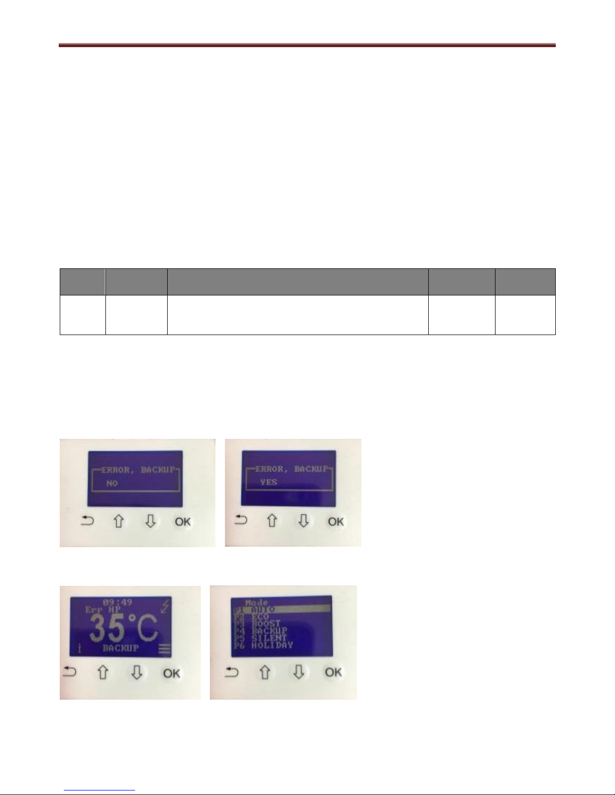
7.4 P4 BACKUP mode
This is an emergency mode. The water is heated up by the electric heater only at a lower set
temperature. The water temperature set point is set in the installer menu, D12 (Backup T).
In the case of an error, a message is displayed on the LCD display requesting if Back Up mode is
required. There is a yes/no input selection required to activate or disable.
The legionella control remains active.
Code
Set Point
Name
Description
Range
Factory
setting
D12
Backup T
The temperature level at which the El heater
heats the water when BACK UP mode is
activated /selected
0 ~ 65
35
EL starts when BBT3 (T Tank t) < D12 (BACKUP T) -5°C
EL stops when BBT3 (T Tank t) = D12 (BACKUP T)
Note: Back up mode can only be deactivated after rectifying the cause of the fault. Once the fault
has been repaired a power cycle (Off/ On) is required to reset the error code. Normal operation
can be resumed by pressing the arrow, up or down, buttons to select the required operating mode.
If an error occurs, using the up or down buttons, select Yes or No, if no is selected the unit has No
operation.
If Yes is selected the DHW-HP changes to BACKUP operation and the unit operates at the
BACKUP mode temperature setting from D12.
After fault rectification and power reset, using the mode selection screen, choose operation mode.
Page 20
Domestic Hot Water Heat Pump Service Manual
19
7.5 P5 SILENT mode
This mode decreases the fan speed to D5 (Min fan speed) in order to minimize the sound
emissions
The DHW-HP is controlled by the A1 AUTO operation mode
The unit starts when BBT3 (T Tank t) < A1 (T AUTO) -5°C
The unit stops when BBT3 (T Tank t) = A1 (T AUTO)
System operating in AUTO mode
Operating mode changed to SILENT.
Fan speed lowers from D6 (AUTO Speed) SP of 57% (factory set point) to D5 (Min Fan Speed)
SP of 40% (factory set point)
Operating mode returned to AUTO mode
Fan speed raises from D5 (Min Fan Speed) SP of 40% to D6 (AUTO speed) of 57%
Note: In SILENT mode the controlled temperature set point is from AUTO mode.
7.6 P6 HOLIDAY mode
DHW-HP does not start when the water heating is required. The HP is OFF except during
Legionella control, which is still activated once a week on the selected day from D15 (Legionella
date).
The HOLIDAY mode is connected to B4 (Hot on Time). After the HOLIDAY period is completed,
the unit goes back to the previous mode of operation.
0
10
20
30
40
50
60
70
80
90
00:00:00
00:00:40
00:01:20
00:02:00
00:02:40
00:03:20
00:04:00
00:04:40
00:05:20
00:06:00
00:06:40
00:07:20
00:08:00
00:08:40
00:09:20
00:10:00
00:10:40
00:11:20
00:12:00
00:12:40
00:13:20
00:14:00
00:14:40
00:15:20
00:16:00
00:16:40
00:17:20
00:18:00
00:18:40
00:19:20
00:20:00
00:20:40
00:21:20
00:22:00
00:22:40
00:23:20
00:24:00
00:24:40
00:25:20
00:26:00
00:26:40
00:27:20
00:28:00
00:28:40
00:29:20
00:30:00
00:30:40
00:31:20
Temperature (°C)
T1 T air in T2 air out T3 T water top
FanSpeedSet R3 Fan R4 HP
Fan OFF
Fan ON
Comp OFF
Comp ON
Page 21

Domestic Hot Water Heat Pump Service Manual
20
7.7 B4 Hot on time
The unit can be programmed to deliver hot water from 1 to 30 days from the moment in which the
function is activated and the HOLIDAY mode is selected.
The unit switches to A1 AUTO mode after the desired number of days is reached. If OFF is
selected the function is not active.
i.e. To set a 7 day Hot on Time function
1. Push the ‘OK’ button for the main menu
2. Use the Up or Down arrows to highlight ‘B Functions’ menu and push the ‘OK’ button
3. Use the Up or Down arrows to highlight ‘B4 Hot on Time’ and push the ‘OK’ button.
4. Use the Up and Down arrows to select the number of days required for the unit to switch on to
A1 AUTO mode and push the ‘OK’ button.
The duration of the HOLIDAY mode is now set.
Note: This function is not activated until ‘HOLIDAY’ is selected from the mode selection screen,
accessed by pushing the Up or Down arrow from the home screen.
7.8 B3 Low Tariff
The low tariff allows the electric heater and the heat pump to run only during periods with low
electricity prices, according to the menu item that regulate the program of the low tariff D17/ D18
(Low tariff weekday/weekends). The unit runs only during pre-defined hours of the day.
Code
Set point
name
Description
Range
Factory
setting
B3
Low Tariff
Standard
If the PV function (B5) is active, this allows the electric heater and the heat
pump to run outside the low tariff period.
OFF/
Standard/
Optimal 1/
Optimal 2
OFF
Low Tariff
Optimal 1
This function allows the maximum exploitation of the lower electricity price
during the night periods between 00:00 and 05:00
Low Tariff
Optimal 2
This function allows the maximum exploitation of the lower electricity price
during the night periods between 00:00 and 05:00.
During the day, the unit works according to Low Tariff periods D17 and D18
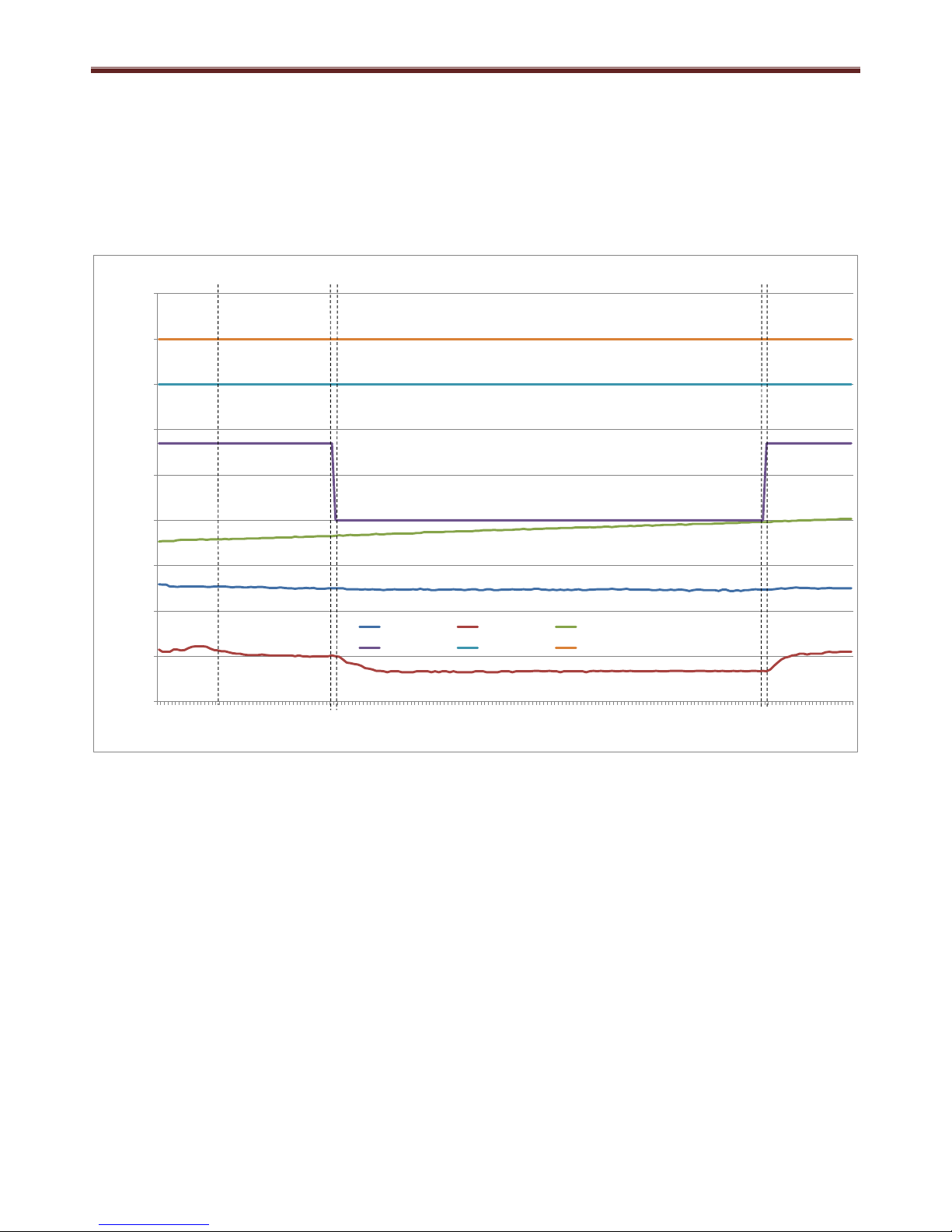
Electric heater operation (Optimal 1 and Optimal 2)
The EL can operate only at night, between 01:00 and 05:00
The EL starts operating when the amount of heat that can be produced by the HP (Qdisp) is not
sufficient to cover the amount of heat needed to reach the water temperature set point by 5:00
(Qreq).
The EL cannot operate more than3 hours/day. 2 other hours are used to calculate the Qreq and
Qdisp (normallybetween00:00-01:00 and 02:00-03:00) and EL cannot be used in these periods.
The EL, if activated, works for at least one continuous hour.
If the water set point temperature has not been reached by 4:00, EL will operate for the last
hour(until05:00), or until the water temperature set point is reached.
In normal conditions, the EL is activated only if also the HP is active.
If the heat pump is not operating, the EL will be activated only in case the external ambient
conditions don’t allow HP operation (Inlet air temperaturebelow-7°C or above40 °C.
Page 22
Domestic Hot Water Heat Pump Service Manual
21
Heat pump operation (Optimal 1 and Optimal 2)
If the water temperature is below set point temperature minus hysteresis, the HP starts its operation
(normally at 00:00).
Optimal 1: The HP is allowed to run also during the day(according to MODE of operation
Optimal 2: The HP is always allowed to run in the night period(between00:00 and 5:00) plus it is
allowed to run in the periods described by D17/D18 (Low tariff period weekday/weekend)
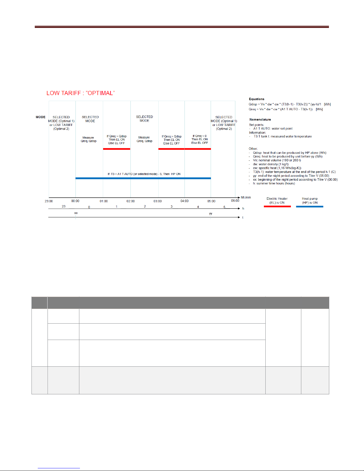
7.9 B1 Ventilation
This mode is used for the ventilation of air from a room and distributed either into the DHW-HP
room location or ducted outside of the building.
Using the function B1 (Ventilation) the DHW-HP can be set to 3 operation modes, Off, single
speed or 2 speed
To complete the ventilation mode setup B2 (Ventilation Fan Speed) can be set.
Code
Set point
name
Description
Range
Factory
setting
B1
Ventilation
OFF
The fan switches off when the heat pump does not run.
OFF/
Single
Speed/
2Speeds
OFF
Single
speed
The fan is always running at a single fixed speed (B2 Fan speed), both
when the heat pump is operating and when it is not.
2 Speeds
The fan is always in operation but it runs normally at a higher speed D6
(Fan AUTO Speed) when the heat pump starts operating and at (B2 Fan
speed) when it is not operating.
B2
Fan speed
The main fan speed regulation for the ventilation function. There are
three ventilation level that can be selected: LOW D5 (Min Fan Speed),
MEDIUM D4 (Fan medium speed) HIGH D3 (Max fan speed).
LOW/
MEDIUM/
HIGH
HIGH
Page 23
Domestic Hot Water Heat Pump Service Manual
22
Single Speed Operation 2 Speed Operation
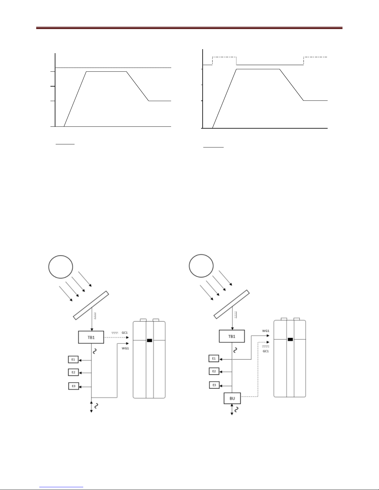
7.10 B5 Photovoltaic
The domestic hot water heat pump (DHWHP) can be controlled by a signal from a solar
photovoltaic (PV) converter or an energy meter, either as simple start/stop via a potential free
contact or by a variable signal.
The diagrams below represent possible installation configurations with or without energy meter.
Using the variable signal option, a certain output (VDC or mA) from the (PV) inverter or the
energy meter corresponds to a given amount of excess power for use in the DHWHP. This
excess power can be used to activate either the electrical immersion heater, the heat pump (HP)
or both.
PV installation 1: control signal from inverter. PV installation 2: control signal from energy meter.
\
T3:Temperature Tank Top
DHW AUTO mode set point of 53°C
Ventilation ON
Ventilation fan speed LOW
Ventilation mode single speed
Note: This may have an impact on performance due to fan reduction in DHW mode
Temperature °C
Fan
Auto
Low5350
48
12
T3:Temperature Tank Top
DHW AUTO mode set point of 53°C
Ventilation ON
Ventilation fan speed LOW
Ventilation mode 2 speed
Auto
4812Low
Fan
Temperature °C
53
50
TB1: DC/AC Inverter
BU: Energy meter
E1-2-3: Electric loads
WG1: Heat pump
power supply
GC1: Photovoltaic
function input
signal (0-10
VDC 0-3 VDC,
4-20 mA).
Page 24

Domestic Hot Water Heat Pump Service Manual
23
A graph to convert the signal input to % is available in figure 21
Conversion table of the controller input signal to percentage
The following schematic shows the electrical connections for the Solar PV operation
BLU
B (D-)
N
L
0V
0V
L
L
0V
0~10V
Input
BT3
EB1
0V0V0V
FM
BT2
BT1
0V
0V
L
N
PE
230VAC ~ 50Hz
0V
A (D+)
0V BLU
0~10V PWM
YEL
High pressure switch.
Compressor STOP when
Pd ≥ 2.0MPa
Solenoid valve.
Solenoid ON for 2 min
before compressor
starts and during
system defrost
BRN
BLK
N
BLU
BLK
BRN
BRN
BLU
Inverter
Solar
PV
BT4
Page 25

Domestic Hot Water Heat Pump Service Manual
24
PV operation is set up using a combination of the following functions:
Code
Set point
name
Description
Range
Factory
setting
B5
OFF
The PV function is not active. If this function is activated, the heat pump
and the electric heater can start only if the input voltage in GC1 (0-10V)
is higher than D20/D21 (PV min Voltage HP/EL) for longer than D22 (PV
min time).
OFF/ ECO/
STORAGE
ECO
PV ECO
The PV function allows for water heating only with the heat pump until
temperature set point defined by the MODE of operation is reached.
PV STORAGE
The PV function allows for water heating to the maximum temperature
level, giving priority to the operation of the heat pump if the BOOST or
BACK UP mode is not active. The heat pump operates alone until the
max allowed temperature for the heat pump operation D33 (T HP Max)
is reached. The electric heater operates only from D33 to the maximum
allowable temperature D9 (Water T max).
D20
PV min
Voltage HP
The minimum voltage (V) required to start the HP
when the PV function is active.
0-10
0
D21
PV min
Voltage EL
The minimum voltage (V) required to start the electric heater when
the PV function is active.
0-10
0
D22
PV min time
The minimum time (minutes) at which the input voltage from the PV
panel should be above the set point D20/D21 (PV min Voltage HP/EL)
in order to start the electric heater or heat pump when the PV function
is active D22 also regulates the minimum heat pump operational time
when started by the PV function.
1-120
15
The following operational charts have these settings applied:
i) D20 (PV min voltage HP) set to 5V
ii) D21 (PV min voltage EL) set to 8V
iii) D22 (PV min time) set to 5mins
iv) PV mode selected from B5 dependant on operation required (ECO or STORAGE)
Page 26

Domestic Hot Water Heat Pump Service Manual
25
7.10.1 PV ECO operation in AUTO mode
When the photovoltaic mode is set to PV ECO and the DHW-HP mode is set to AUTO, there is no
operation of the electrical heater, even if the 0~10V input rises above the D21 (PV Min Voltage EL)
set point.
0~10V input raised in small steps until >5V, set from D20 (PV Min Voltage HP)
HP starts after 5 minutes delay, set from D22 (PV Min Time)
In ECO / AUTO mode the heater should not operate, Voltage raised to >8V D21 (PV Min Voltage
EL)
0~10V input decreased until <5V, set from D20 (PV Min Voltage HP)
HP stops after 5 minutes delay, set from D22 (PV Min Time)
Note: If water set point temperature is achieved then the heat pump stops operation.
0
1
2
3
4
5
6
7
8
9
10
11
12
13
14
0
10
20
30
40
50
60
70
80
90
00:00:00
00:01:20
00:02:40
00:04:00
00:05:20
00:06:40
00:08:00
00:09:20
00:10:40
00:12:00
00:13:20
00:14:40
00:16:00
00:17:20
00:18:40
00:20:00
00:21:20
00:22:40
00:24:00
00:25:20
00:26:40
00:28:00
00:29:20
00:30:40
00:32:00
00:33:20
00:34:40
00:36:00
00:37:20
00:38:40
00:40:00
00:41:20
00:42:40
00:44:00
00:45:20
00:46:40
00:48:00
00:49:20
00:50:40
00:52:00
00:53:20
00:54:40
00:56:00
00:57:20
00:58:40
01:00:00
01:01:20
01:02:40
01:04:00
01:05:20
01:06:40
01:08:00
Voltage
Temperature
Time
T3 T water top R3 Fan R4 HP
R5 El heater V in (0-10V)
Fan Off
Fan On
HP Off
HP On
El H Off
El H On
Fan Off
Fan On
HP Off
HP On
El H Off
El H On
Fan Off
Fan On
HP Off
HP On
El H Off
El H On
Page 27

Domestic Hot Water Heat Pump Service Manual
26
7.10.2 PV ECO operation in BOOST mode
When the photovoltaic mode is set to PV ECO and the DHW-HP mode is set to BOOST, there is no
operation of the electrical heater, even if the 0~10V input rises above the D21 (PV Min Voltage EL)
set point.
0~10V input raised until >8V, set from D20 (PV Min Voltage HP) & D21(PV Min Voltage EL)
HP starts after 5 minutes delay, set from D22 (PV Min Time). Electric heater does not start due to
PV ECO mode being selected.
0~10V input decreased until <5V, set from D20 (PV Min Voltage HP)
HP stops after 5 minutes delay, set from D22 (PV Min Time)
Note: If water set point temperature is achieved then the heat pump stops operation.
0
1
2
3
4
5
6
7
8
9
10
11
12
13
14
0
10
20
30
40
50
60
70
80
90
00:00:00
00:01:10
00:02:20
00:03:30
00:04:40
00:05:50
00:07:00
00:08:10
00:09:20
00:10:30
00:11:40
00:12:50
00:14:00
00:15:10
00:16:20
00:17:30
00:18:40
00:19:50
00:21:00
00:22:10
00:23:20
00:24:30
00:25:40
00:26:50
00:28:00
00:29:10
00:30:20
00:31:30
00:32:40
00:33:50
00:35:00
00:36:10
00:37:20
00:38:30
00:39:40
00:40:50
00:42:00
00:43:10
00:44:20
00:45:30
00:46:40
00:47:50
00:49:00
00:50:10
00:51:20
00:52:30
00:53:40
00:54:50
00:56:00
00:57:10
00:58:20
00:59:30
01:00:40
01:01:50
Voltage
Temperature
Time
T3 T water top R3 Fan R4 HP R5 El heater V in (0-10V)
Fan Off
Fan On
HP Off
HP On
El H Off
El H On
Page 28

Domestic Hot Water Heat Pump Service Manual
27
7.10.3 PV Storage operation in BOOST mode
When the photovoltaic mode is set to PV STORAGE and the DHW-HP mode is set to BOOST, the
HP operates when the 0~10V input rises above the D20 (PV Min Voltage HP) and the electrical
heater operates when the 0~10V input rises above the D21 (PV Min Voltage EL) set point.
0~10V input raised in small steps until >5V, set from D20 (PV Min Voltage HP)
HP starts after 5 minutes delay, set from D22 (PV Min Time)
0~10V input raised in small steps until >8V, set from D21 (PV Min Voltage EL)
EL starts after 5 minutes delay, set from D22 (PV Min Time)
0~10V input decreased until <8V, set from D20 (PV Min Voltage HP)
EL stops after 5 minutes delay, set from D22 (PV Min Time)
0~10V input decreased until <5V, set from D20 (PV Min Voltage HP)
HP stops after 5 minutes delay, set from D22 (PV Min Time)
Note: If water set point temperature is achieved then the heat pump stops operation.
0
1
2
3
4
5
6
7
8
9
10
11
12
13
14
0
10
20
30
40
50
60
70
80
90
00:00:00
00:01:10
00:02:20
00:03:30
00:04:40
00:05:50
00:07:00
00:08:10
00:09:20
00:10:30
00:11:40
00:12:50
00:14:00
00:15:10
00:16:20
00:17:30
00:18:40
00:19:50
00:21:00
00:22:10
00:23:20
00:24:30
00:25:40
00:26:50
00:28:00
00:29:10
00:30:20
00:31:30
00:32:40
00:33:50
00:35:00
00:36:10
00:37:20
00:38:30
00:39:40
00:40:50
00:42:00
00:43:10
00:44:20
00:45:30
00:46:40
00:47:50
00:49:00
00:50:10
00:51:20
00:52:30
00:53:40
00:54:50
00:56:00
00:57:10
00:58:20
00:59:30
01:00:40
01:01:50
Voltage
Temperature
Time
T3 T water top R3 Fan
R4 HP R5 El heater
V in (0-10V)
Fan Off
Fan On
HP Off
HP On
El H Off
El H On
Page 29

Domestic Hot Water Heat Pump Service Manual
28
7.11 D26 Extra Function (Only available with the deluxe DHW-HP)
There are 3 additional modes available for the Deluxe model DHW-HP, solar, floor heating and
cooling functions. These are activated from D26 Extra Function accessed within the Installer
menu.
NOTE: It is only possible to connect one of these options to the DHW-HP at any time.
Code
Set point
name
Description
Range
Factory
setting
D26
Extra function
The desired extra function is selected here. The possible functions are
Solar, Floor or Cooling. Once the function is activated, move to the function
menu and adjust the set point as desired.
OFF/
Solar/
Floor/
Cooling
OFF
7.11.01 B6 Solar
The Solar function allows the water to be heated up by the solar collector, activating a water pump
controlled by the extra relay (GP1).
The setup of the solar function is carried out using the function menu and B6 (Solar)
Code
Set point
name
Description
Range
Factory
setting
B6
Solar
The Solar function allows the water to be heated up by the solar collector,
activating a water pump controlled by the extra relay (GP1). The pump
starts when BT5 > BT3 + D24 (Solar DT min). The pump stops if the
temperature in the tank goes above D23 (Solar T max) or if BT5 is below
BT3.
OFF/ON
OFF
The following schematic shows the electrical connections for the Solar Thermal operation
BLU
B (D-)
N
L
0V
0V
L
L
0V
0~10V
Input
BT3
EB1
0V0V0V
FM
BT2
BT1
0V
0V
L
N
PE
230VAC ~ 50Hz
0V
A (D+)
0V BLU
0~10V PWM
YEL
High pressure switch.
Compressor STOP when
Pd ≥ 2.0MPa
Solenoid valve.
Solenoid ON for 2 min
before compressor
starts and during
system defrost
BRN
BLK
N
BLU
BLK
BRN
BRN
BLU
Solar
Thermal
BT5
BT4
Page 30

Domestic Hot Water Heat Pump Service Manual
29
7.11.02 B7 Floor / B8 Floor T
The floor heating function activates an external circulation pump, controlled by the extra relay
(GP1)
The setup of the floor heating function is carried out using the function menu and B7 (Floor) & B8
(Floor T)
Code
Set point
name
Description
Range
Factory
setting
B7
Floor
If the temperature at the bottom of the tank BT4 (T water b) is higher than
the setting menu D25 (Floor T start) the floor heating function is activated.
If the extra temperature BT5 (T Extra) is higher than the floor heating
temperature (B8 T floor) the circulation pump (Extra relay GP1) stops.
OFF/ON
OFF
B8
Floor T
The desired floor heating temperature in °C with hysteresis of 1K.
15 - 40
35
The following schematic shows the electrical connections for the underfloor heating operation
ON
OFF
PUMP
22
2112292330
Tank Temperature °C
Floor Temperature °C
T4: Temperature Tank Bottom Control
T5: Floor Temperature
Based on following set conditions
Installer menu
D24: Floor Set Start = 30°C (T4)
D26: Extra Function = Floor
Function menu
B7: Floor = ON
B8: Floor Temp = 22°C (T5)
BLU
B (D-)
N
L
0V
0V
L
L
0V
0~10V
Input
BT3
EB1
Room Temperature
0V0V0V
FM
BT2
BT1
0V
0V
L
N
PE
230VAC ~ 50Hz
0V
A (D+)
0V BLU
0~10V PWM
YEL
High pressure switch.
Compressor STOP when
Pd ≥ 2.0MPa
Solenoid valve.
Solenoid ON for 2 min
before compressor
starts and during
system defrost
BRN
BLK
N
BLU
BLK
BRN
BRN
BLU
BT5
BT4
Page 31

Domestic Hot Water Heat Pump Service Manual
30
7.11.03 B9 Cooling / B10 Cooling T
The cooling function activates a three-way damper, which directs the cold exhaust air to a room
with cooling requirements. The two functions operate the damper in opposite directions.
The Cooling function allows an area to be cooled up by the DHW-HP exhaust air, activating a
damper motor controlled by the extra relay (GP1).
The setup of the cooling function is carried out using the function menu B9 (Cooling) & B8
(Cooling T) and installer menu D28 m(Cooling type)
Code
Set point
name
Description
Range
Factory
setting
B9
Cooling
The Cooling function can be activated. See installer menu D28 (Cooling
type).
OFF/ON
OFF
B10
Cooling T
The air temperature set point (°C) below which the heat pump stops,
when the unit is in the Cooling function.
10 - 30
21
D28
Cooling 1
The fan and heat pump run until the additional temperature sensor, BT5,
placed in the room environment is below a certain level. The water
temperature can only reach the maximum temperature allowed in the tank
D33 (T HP max). The cooling function activates a three-way damper, which
directs the cold exhaust air to a room with cooling requirements. The two
functions operate the damper in opposite directions
Cooling1 /
Cooling2
Cooling1
Cooling 2
Cooling 1 (2). If BT5 is higher than B10 T Cooling, the extra relay that
operates the damper (GP1) switches ON (OFF).
If BT5 is lower than B10 (T Cooling), the extra relay that operate the
damper (GP1) switches OFF (ON).
The following schematic shows the electrical connections for the cooling operation
BLU
B (D-)
N
L
0V
0V
L
L
0V
0~10V
Input
BT3
EB1
0V0V0V
FM
BT2
BT1
0V
0V
L
N
PE
230VAC ~ 50Hz
0V
A (D+)
0V BLU
0~10V PWM
YEL
High pressure switch.
Compressor STOP when
Pd ≥ 2.0MPa
Solenoid valve.
Solenoid ON for 2 min
before compressor
starts and during
system defrost
BRN
BLK
N
BLU
BLK
BRN
BRN
BLU
BT5
Underfloor
heating
or
Cooling
Room
temperature
BT4
Page 32

Domestic Hot Water Heat Pump Service Manual
31
7.12 D27 SG Ready
A smart grid is an electrical grid which includes a variety of operational and energy
measures including smart meters, smart appliances, renewable energy resources,
and energy efficient resources. Electronic power conditioning and control of the
production and distribution of electricity are important aspects of the smart grid.
The DHW-HP is controlled based on inputs received from the Smart Grid energy
meter on QA1and set up using installer menu D27.
Code
Set point
name
Description
Range
Factory
setting
D27
SG
Ready
The SG ready function can be activated by the installer here. Three
possible modes can be selected. This function allows the start of the heat
pump from an external access (See QA1).
OFF
OFF
The heat pump and electric heater must start, if below the max water
temperature allowed in the tank. Both Heat Pump and Electric heater are
forced to operate (SG1 ON and SG2 ON).
SG
BOOST
The heat pump operates minimizing costs, only the heat pump is activated
(SG1 OFF, SG2 ON).
SG ECO
The unit can be stopped even if there is a need for hot water (SG1 ON,
SG2 OFF).
SG
BLOCK
OFF
<53
19
ON
T Extra Temperature °C
Tank T °C
25
21
HP Operation
20
65
53
DHW
Set Point
>53
OFF
Aux
ON
T3:Temperature Tank Top
T5: Temperature Extra (Room)
Cooling
Type 1
Cooling temperature set point 20°C
Note: If DHW temperature is greater than Auto set point (>53°C)
then HP OFF when Cool satisfied
If cooling demand during this time then HP start at 65°C set point
CAUTION: DHW temperature could be hot 60°C
DHW AUTO mode set point of 53°C
Tank T °C
T Extra Temperature °C
252120
DHW
Set Point
Aux
OFF
65
ON
53
19
HP Operation
<53
ON
>53
OFF
T3:Temperature Tank Top
T5: Temperature Extra (Room)
Cooling
Type 2
Cooling temperature set point 20°C
Note: If DHW temperature is greater than Auto set point (>53°C)
then HP OFF when Cool satisfied
If cooling demand during this time then HP start at 65°C set point
CAUTION: DHW temperature could be hot 60°C
DHW AUTO mode set point of 53°C
Page 33

Domestic Hot Water Heat Pump Service Manual
32
The following schematic shows the electrical connections for the SG Ready operation
BLU
B (D-)
N
L
0V
0V
L
L
0V
0~10V
Input
BT3
EB1
Energy Meter
Communication to
/ from power grid
SG2
SG1
0V0V0V0V0V
FM
BT2
BT1
0V
0V
L
N
PE
230VAC ~ 50Hz
0V
A (D+)
0V BLU
0~10V PWM
YEL
High pressure switch.
Compressor STOP when
Pd ≥ 2.0MPa
Solenoid valve.
Solenoid ON for 2 min
before compressor
starts and during
system defrost
BRN
BLK
N
BLU
BLK
BRN
BRN
BLU
#2
TB1: DC/AC Inverter
BU: Energy meter
E1-2-3: Electric loads
WG1: Heat pump power supply
GC1: Photovoltaic function
input signal (0-10 VDC 03 VDC, 4-20 mA).
____: represents the cables to
the switch inputs SG1 &
SG2
E1
E2
E3
BU - Smart Grid
Energy Meter
GC1
WG1
TB1
From the Grid
SG1
SG2
TOSHIBA
Page 34

Domestic Hot Water Heat Pump Service Manual
33
DHW-HP normal operation
SB Block – SG switch positions: SG1 ON, SG2 Off – DHW-HP stops operation
SG Boost – SG switch positions; SG1 On, SG2 On – DHW-HP operates with HP & EL Heater
SG Eco – SG Switch positions; SG1 Off, SG2 On – DHW-HP operates with HP only
When DHW-HP reaches mode set point (AUTO mode = 53.5°C), DHW-HP stops operation
7.13 D29 External control
This function allows for the external control of the ventilation function using a 0 ~ 10 Volt input.
Using the installer menu, D29 (External control) function.
Code
Set point
name
Description
Range
Factory
setting
D29
OFF
Normal operation.
OFF/
Hygrostat/
Ventilation
Max/
Start-Stop
OFF
Hygrostat
The fan always runs according to the input signal in GC1 (0-10V) from an
external hygrostat, CO2 – sensor or similar appliances.
1. If the voltage is between 0-3.0V the fan speed id D5 (Fan min speed)
2. If the voltage is between 3.0-8.0V the fan speed is D4 (Fan medium
speed)
3. If the voltage is higher than 8V the fan speed is D3 (Fan max speed)
Ventilation
max
If the ventilation function is already selected,
a signal higher of 2V to GC1 leads to maximum air flow.
Start/
Stop
If GC1 receives a signal higher than 2V, the unit operation is stopped.
0
20
40
60
80
100
120
11:56:00
11:59:00
12:02:00
12:05:00
12:08:00
12:11:00
12:14:00
12:17:00
12:20:00
12:23:00
12:26:00
12:29:00
12:32:00
12:35:00
12:38:00
12:41:00
12:44:00
12:47:00
12:50:00
12:53:00
12:56:00
12:59:00
13:02:00
13:05:00
13:08:00
13:11:00
13:14:00
13:17:00
13:20:00
13:23:00
13:26:00
13:29:00
13:32:00
13:35:00
13:38:00
13:41:00
13:44:00
13:47:00
13:50:00
13:53:00
13:56:00
13:59:00
14:02:00
14:05:00
14:08:00
14:11:00
14:14:00
14:17:00
14:20:00
14:23:00
14:26:00
14:29:00
T3 T water top R4 HP R5 El Heate r
SG1 input SG2 input SG state
HP_OnTemp HP_OffTemp
HP Off
HP On
EL Off
EL On
SG1 Off
SG1 On
SG2 Off
SG2 On
SG Off
SG Block
SG1 Eco
SG1 Boost
Page 35

Domestic Hot Water Heat Pump Service Manual
34
Hygrostat Function – fan speed control
The air flow is automatically adjusted depending on the ambient air conditions or by manual
adjustments.
The fan constantly runs changing the speed level depending on the 0~10V input signal from
external humidity sensors, CO2 sensors or human interface panel:
When the input signal is from 0 to 3.3V, the fan switches to minimum speed level (from D5)
When the input signal is from 3.3 to 8V, the fan switches to medium speed level (from D4)
When the input signal is from 8 to 10V, the fan switches to high speed level (from D3)
Humidity / CO2 Sensor
Human Interface
Humidity / CO2 Sensor
Receiver
Room 1
Room 2
BLU
B (D-)
N
L
0V
0V
L
L
0V
0~10V
Input
BT3
EB1
0V0V0V
FM
BT2
BT1
0V
0V
L
N
PE
230VAC ~ 50Hz
0V
A (D+)
0V BLU
0~10V PWM
YEL
High pressure switch.
Compressor STOP when
Pd ≥ 2.0MPa
Solenoid valve.
Solenoid ON for 2 min
before compressor
starts and during
system defrost
BRN
BLK
N
BLU
BLK
BRN
BRN
BLU
Page 36

Domestic Hot Water Heat Pump Service Manual
35
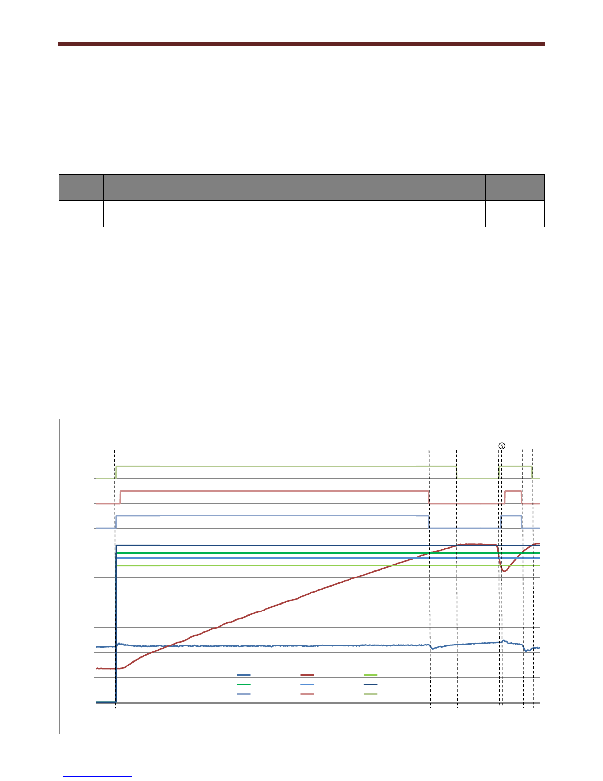
7.14 Defrost operation
When the evaporation temperature (BT2) falls below 0°C, the evaporator starts to accumulate ice
on its fins. In order to maintain the unit reliability and performance, an automatic defrosting
operation is activated.
Defrosting can occur between 60 minutes and 120 minutes from the last defrosting or from the
last moment in which the evaporation temperature was above 0°C.
Defrosting can occur with two different strategies according to the conditions of the inlet air.
1) If the air temperature is above 4°C, then the defrosting occurs running both compressor and
fan. The fan runs at speed D3 (Fan max speed).
2) If the air temperature is below 4°C, then the defrosting occurs running the compressor and
stopping the fan.
Before defrosting is completed the fan stops for a short period to allow the excess water in the
unit to leave the unit from the condensate drain.
Defrosting automatically stops when the temperature of the evaporator (BT2)
becomes higher than the set point (D10).
-5
5
15
25
35
45
55
65
75
85
95
00:00:00
00:05:50
00:11:40
00:17:30
00:23:20
00:29:10
00:35:00
00:40:50
00:46:40
00:52:30
00:58:20
01:04:10
01:10:00
01:15:50
01:21:40
01:27:30
01:33:20
01:39:10
01:45:00
01:50:50
01:56:40
02:02:30
02:08:20
02:14:10
02:20:00
02:25:50
02:31:40
02:37:30
02:43:20
02:49:10
02:55:00
03:00:50
03:06:40
03:12:30
03:18:20
03:24:10
03:30:00
03:35:50
03:41:40
03:47:30
03:53:20
03:59:10
04:05:00
04:10:50
04:16:40
04:22:30
04:28:20
04:34:10
04:40:00
04:45:50
04:51:40
Temperature (°C)
T1 T air in T2 air out
T3 T water top FanSpeedSet
R2 Defrost DefrostState
Defrost Valve
ON
Defrost Valve
OFF
Defrost OFF
Defrost Timer
Defrost ON
Fan OFF
Fan Auto
Speed
Fan Max
Speed
Page 37

Domestic Hot Water Heat Pump Service Manual
36
System start up with BT1 (Air Inlet Temp) at 3°C
After 60 minute operation the defrost countdown timer is activated
After a further 60 minutes, the DHW-HP enters defrost operation
The solenoid valve opens and because the BT1 temperature is <4°C the compressor stays on
and the fan stops operation
Defrost operation stops after a maximum time limit of 12 minutes or when BT2 (T Air Out),
evaporator temperature, becomes higher than the set point of D10 (Defrosting Temp Stop),
factory set to 4°C.
BT1 (Air Inlet Temp) raised to 4.2°C
After a further 60 minutes, the DHW-HP enters defrost operation
The solenoid valve opens and because the BT1 temperature is >4°C the compressor and fan
operate. The fan increases operation to Max Fan Speed, D3 (Fan Speed Max) set point.
Defrost operation stops after a maximum time limit of 12 minutes or when BT2 (T Air Out),
evaporator temperature, becomes higher than the set point of D10 (Defrosting Temp Stop),
factory set to 4°C.
7.15 Legionella operation
In order to prevent the possibility of legionella bacteria accumulating in the DHW-HP, a
pasteurisation, or anti-legionella cycle, should be performed weekly.
Using the installer menu set up parameters D13 to D15 (detailed below). It is possible to select the
day, temperature and to enable or disable the anti-legionella cycle.
The anti-legionella cycle is activated at midnight (00:00) on the day set (code D15) but the higher
temperature is not activated until the next compressor start operation (DHW demand condition).
Note:
i) If there is no DHW demand, and therefore no compressor start, within 24 hours of the anti-
legionella control becoming active the anti-legionella control is forced to start regardless of
the water temperature inside the DHW-HP
ii) When the DHW-HP is set in HOLIDAY mode the anti-legionella control operates on the
selected day and starts the heat pump at 00:00.
Code
Set point
name
Description
Range
Factory
setting
D13
Legionella
The legionella function can be activated. The legionella function does not
switch the heat pump on, but just continues the heat up cycle to a higher
temperature D14 (Legionella T). The legionella operation works only with
the heat pump until 60°C. The remaining temperature lift is accomplished
with the electric heater alone.
OFF/ON
OFF
D14
Legionella
Temp
The legionella temperature set point can be regulated.
60-65
60
D15
Legionella
date
The legionella week day can be set
Monday/
Sunday
Sunday
Page 38

Domestic Hot Water Heat Pump Service Manual
37
Anti-legionella control activates at midnight (00:00). No operation of heat pump due to no
demand.
Heat pump starts operation when demand is required and the HP off temperature is raised to
the legionella set point temperature, in this case D14 is set to standard factory setting of 60°C.
Heat pump stops operation when legionella set point is achieved, 60°C.
0
10
20
30
40
50
60
70
80
90
100
16:08:00
16:29:20
16:50:40
17:12:00
17:33:20
17:54:40
18:16:00
18:37:20
18:58:40
19:20:00
19:41:20
20:02:40
20:24:00
20:45:20
21:06:40
21:28:00
21:49:20
22:10:40
22:32:00
22:53:20
23:14:40
23:36:00
23:57:20
00:18:40
00:40:00
01:01:20
01:22:40
01:44:00
02:05:20
02:26:40
02:48:00
03:09:20
03:30:40
03:52:00
04:13:20
04:34:40
04:56:00
05:17:20
05:38:40
06:00:00
06:21:20
06:42:40
07:04:00
07:25:20
07:46:40
08:08:00
08:29:20
08:50:40
09:12:00
09:33:20
09:54:40
10:16:00
10:37:20
10:58:40
Temperature
Time
T3 T water top R3 Fan
R4 HP Legionella State
HP_OffTemp
R3 Fan Off
R3 Fan On
R4 Comp Off
R4 Comp On
Legionella Off
Legionella On
R3 Fan Off
R3 Fan On
R4 Comp Off
R4 Comp On
Legionella Off
Legionella On
1
32
Page 39

Domestic Hot Water Heat Pump Service Manual
38
8.0 Modbus
As standard the Toshiba Domestic Hot Water Heat Pump units are supplied with a ModBus
controller. The controller provides a secondary port to be connected to a system network thanks to
an RS485 bus. The controller has the ability to communicate without an amplifier. The length of
the bus does not exceed 500m.
Description
Line
Spec.
Maximum
Length
(m)
Connection Destination
RS-485
connection
2 wire
shielded
500m
PCB
WF1
Pin 1
A
+RS485
Pin 2
B
-RS485
The following schematic shows the electrical connections for the Modbus operation
BLU
B (D-)
N
L
0V
0V
L
L
0V
0~10V
Input
BT3
EB1
0V0V0V
FM
BT2
BT1
0V
0V
L
N
PE
230VAC ~ 50Hz
0V
A (D+)
0V BLU
0~10V PWM
YEL
High pressure switch.
Compressor STOP when
Pd ≥ 2.0MPa
Solenoid valve.
Solenoid ON for 2 min
before compressor
starts and during
system defrost
BRN
BLK
N
BLU
BLK
BRN
BRN
BLU
Modbus
communication
Page 40

Domestic Hot Water Heat Pump Service Manual
39
ModBus should be set form the installer menu D2, see the table below:
Code
Set point
name
Description
Range
Factory setting
D2
Modbus
D2.1
Address
The Modbus address can be selected
between 1 and 247
1 ~ 247
30
D2.2
Baud Rate
The Modbus baud rate can be selected
or de-activated
9600 ~ 19200
19200
D2.3
Parity
The Modbus parity can be selected or
de-activated
Even /
Odd /
OFF
Even
D2.4
Modify
If this function is activated, it is possible
to modify the set points kept for
development with a data logger
OFF / ON
OFF
Note: Stop bits are factory set to 1.
ModBus can be accessed by means of the XB/WF1 connection and by the use of the micro-USB
connection on the front panel, located under the display surround. The factory settings are
displayed in the table below.
Parameter
MODBUS
Via connector X8/WF1
MODBUS
via USB
Modbus Mode:
RTU
Baud rate:
19200 / 9600 (Default = 19200)
Data bits:
8
Parity:
Even / Odd / None (Default = Even)
Stop bits:
1
Modbus Address
1 ~ 247 (Default = 30)
Only 30
ModBus has 2 control levels.
The first control level is used for monitoring functions only and the second can be used for reading
or writing data depending on the status of installer menu parameter D2.4 ModBus Modify. This
parameter can only be changed by using the controller on the front of the DHW-HP.
Page 41

Domestic Hot Water Heat Pump Service Manual
40
8.1 Monitoring Functions
Modbus
Code
Parameter
Format
Unit
Modbus
Code
Parameter
Format
Unit
3x0000
ADC value CH2
*1 - 3x0021
R3 Fan
*1
OFF/ON
3x0001
ADC value CH3
*1 - 3x0022
R4 HP
*1
OFF/ON
3x0002
ADC value CH4
*1 - 3x0023
R5 El Heater
*1
OFF/ON
3x0003
ADC value CH7
*1 - 3x0024
R6 Pressostat
*1
OFF/ON
3x0004
ADC value CH10
*1 - 3x0025
SG1 Input
*1
OFF/ON
3x0005
ADC value CH11
*1 - 3x0026
SG2 Input
*1
OFF/ON
3x0006
ADC value CH12
*1 - 3x0027
V in (0/3-10V)
*10
Volt
3x0007
ADC value CH13
*1 - 3x0028
Temperature avg air
*10
°C
3x0008
ADC value CH14
*1 - 3x0029
Temperature avg evap
*10
°C
3x0009
ADC value CH15
*1 - 3x0030
El Power
*100
-
3x0011
BT1 T air in
*10
°C
3x0031
Total power
*100
-
3x0012
BT2 T air out
*10
°C
3x0032
Heating C
*100
-
3x0013
BT3 T water top
*10
°C
3x0033
Water P
*100 - 3x0014
BT4 T water low
*10
°C
3x0035
BT1 Error
*1
OFF/ON
3x0015
BT5 T extra
*10
°C
3x0036
BT2 Error
*1
OFF/ON
3x0019
R1 Extra
*1
OFF/ON
3x0037
BT3 Error
*1
OFF/ON
3x0020
R2 Defrost
*1
OFF/ON
3x0038
BT4 Error
*1
OFF/ON
Modbus
Code
Parameter
Format
Unit
Modbus
Code
Parameter
Format
Unit
3x0039
BT5 Error
*1
OFF/ON
3x0058
Max Fan Speed At Start Up
*1
OFF/ON
3x0040
HP Error
*1
OFF/ON
3x0059
Compressor State
*1
OFF/ON
3x0041
Evaporator Error
*1
OFF/ON
3x0060
WP_State Timer
*1
Seconds
3x0042
Cold Evap Error
*1
OFF/ON
3x0061
Defrost Valve Off Timer
*1
Seconds
3x0043
Modbus Error
*1
OFF/ON
3x0062
Compressor On Timer
*1
Seconds
3x0044
Filter Error
*1
OFF/ON
3x0063
T without Defrost Cnt
*1
Seconds
3x0045
HotEvapError
*1
OFF/ON
3x0064
BT3 Stable Cnt
*1
Seconds
3x0047
Fan speed set
*100 % 3x0065
BT1 Stable Cnt
*1
Seconds
3x0048
HP_On temp
*10
°C
3x0066
Fan Stable Cnt
*1
Seconds
3x0049
HP_Off temp
*10
°C
3x0067
BT1 minus BT2 old
*10
°C
3x0050
HP_Released
*1
OFF/ON
3x0068
Defrost On Cnt
*1
Seconds
3x0051
E_Heat On Temp
*10
°C
3x0069
BT1 minus BT2 step
*1
3x0052
E_Heat Off Temp
*10
°C
3x0072
HP_Hours_Sec
*1
Seconds
3x0053
E_Heat Released Level
*1
OFF/ON
3x0073
El_Hours_Sec
*1
Seconds
3x0054
Cold Mode On
*1
OFF/ON
3x0074
Fan_Hours_Sec
*1
Seconds
3x0055
Hot Mode ON
*1
OFF/ON
3x0075
Back Up Mode Rest Time_sec
*1
Seconds
3x0056
Defrost State
*1
OFF/ON
3x0076
Hot On Rest Time_sec
*1
Seconds
3x0057
Defrost Fan Off
*1
OFF/ON
3x0077
Back Up Mode On Time_sec
*1
Seconds
Page 42

Domestic Hot Water Heat Pump Service Manual
41
Modbus
Code
Parameter
Format
Unit
Modbus
Code
Parameter
Format
Unit
3x0077
Back Up Mode On Time_sec
*1
Seconds
3x0096
Optimal Release HP
*1
OFF/ON
3x0078
Filter On Time_sec
*1
Seconds
3x0097
Optimal EL ON
*1
OFF/ON
3x0079
Defrost Run Out Cnt
*1
Seconds
3x0098
Legionella State
*1
-
3x0081
BT1_Error Cnt
*1
Seconds
3x0099
Low Tariff On/Off
*1
3x0082
BT2_Error Cnt
*1
Seconds
3x0100
PV State
*1
Binary
3x0083
BT3_Error Cnt
*1
Seconds
3x0101
SG State
*1
3x0084
BT4_Error Cnt
*1
Seconds
3x0102
Cooling State
*1
3x0085
BT5_Error Cnt
*1
Seconds
3x0103
Extern Control State
*1
3x0086
Pressostat Error Cnt
*1
Seconds
3x0105
Power Fan
*1
3x0087
Evap Error Cnt
*1
Seconds
3x10⁶
Power Compressor
*1 3x0088
Cold Evap Error Cnt
*1
Seconds
3x10⁷
HPWe (Compressor + Fan)
*1 3x0089
Modbus Error Cnt
*1
Seconds
3x111
HPWe Acc Temp Debug
*1 3x0090
HotEvapErrorCnt
*1
Seconds
3x0112
El Acc Temp Debug
*1
3x0093
ErrorList
*1
Binary
3x0113
Water P Acc Temp Debug
*1
3x0095
Fan RPM
*1
RPM
3x0116
Password O K Cnt Down
*1
8.2 Read & write functions
Modbus
Code
Parameter
Read / Write
Modbus Modify
Data
Range
Value
Range
Format
Unit
D02.4 = 0
D02.4 = 1
4x0000
P Mode (0=AUTO 1=ECO 2=BOOST 3=BACKUP 4=SILENT 5=HOLIDAY)
R
R/W 0 ~ 5
*1
-
4x0001
D16.3 Low tariff weekday start hour #2
R
R/W - 0 ~ 23
*1
Hours
4x0002
D16.4 Low tariff weekday end hour #2
R
R/W - 0 ~ 23
*1
Hours
4x0003
D16.5 Low tariff weekday start hour #3
R
R/W - 0 ~ 23
*1
Hours
4x0004
D16.6 Low tariff weekday end hour #3
R
R/W - 0 ~ 23
*1
Hours
4x0005
D17.3 Low tariff weekend start hour #2
R
R/W - 0 ~ 23
*1
Hours
4x0006
D17.4 Low tariff weekend end hour #2
R
R/W - 0 ~ 23
*1
Hours
4x0007
Um8 R R/W - 0
*1
-
4x0008
A1 T Auto
R
R/W
500 ~ 650
50 ~ 65
*10
°C
4x0009
A2 T ECO
R
R/W
500 ~ 550
50 ~ 55
*10
°C
4x0010
A3 BOOST
R
R/W
500 ~ 650
50 ~ 65
*10
°C
4x0011
D17.5 Low tariff weekend start #3
R
R/W - 0 ~ 23
*1
Hours
4x0012
D17.6 Low tariff weekend end hour #3
R
R/W - 0 ~ 23
*1
Hours
4x0013
B01 Ventilation (0=OFF, 1=Single speed, 2=2xSpeed)
R
R/W - 0 ~ 2
*1
-
4x0014
B02 Ventilation Speed (0=Low, 1=Medium, 2=High)
R
R/W - 0 ~ 2
*1 - 4x0015
B03 Low tariff (0=OFF, 1=Standard, 2=EL Optimal 1, 3=EL Optimal 2)
R
R/W - 0 ~ 3
*1
OFF/ON
4x0016
B04 Hot on time
R
R/W - 0 ~ 30
*1
Days
4x0017
B05 PV (0=OFF, 1=ECO, 2=STORAGE)
R
R/W - 0 ~ 2
*1
-
4x0018
B06 Solar 1( = ON)
R
R/W - 0 ~ 1
*1
OFF/ON
Page 43

Domestic Hot Water Heat Pump Service Manual
42
Modbus
Code
Parameter
Read / Write
Modbus Modify
Data
Range
Value
Range
Format
Unit
D02.4 = 0
D02.4 = 1
4x0019
B07 Floor (1 = ON)
R
R/W - 0 ~ 1
*1
OFF/ON
4x0020
B08 Floor temperature
R
R/W
50 ~ 500
5 ~ 50
*10
°C
4x0021
B09 Cooling (1 = ON)
R
R/W - 0 ~ 1
*1
OFF/ON
4x0022
B10 Cooling temperature
R
R/W
100 ~ 300
10 ~ 30
*10
°C
4x0023
Um24 R R/W - 0
*1 4x0024
Sm1 R R/W - 0
*1
4x0025
C0 Reset (1 = Reset)
R
R/W - 0 ~ 1
*1
NO/YES
4x0026
C1.1 Model
R R -
0 ~ 65535
*1
Seconds
4x0027
C1.2 Software
R R 0 ~ 65530
0 ~ 6553
*10
Seconds
4x0028
C1.3 Version
R R -
0 ~ 65535
*1 - 4x0029
C2.1 Hour
R
R/W - 0 ~ 23
*1
Hours
4x0030
C2.2 Minutes
R
R/W
-
0 ~ 23
*1
Minutes
4x0031
C3.1 Date
R
R/W - 0 ~ 31
*1
Days
4x0032
C3.2 Month
R
R/W - 0 ~ 12
*1
Month
4x0033
C3.3 Year
R
R/W - 0 ~ 99
*1
Year
4x0034
C4 Day (1=Monday 7=Sunday)
R
R/W - 1 ~ 7
*1
DoW
4x0035
C5 Language (0=UK, 1=DE, 2=FR, 3=DK, 4=NL, 5=PL, 6=ITA)
R
R/W - 0 ~ 6
*1
-
4x0036
C6 Contrast
R
R/W - 0 ~ 8
*1
-
4x0038
D0 Reset All (1 = Reset)
R
R/W - 0 ~ 1
*1
NO/YES
4x0039
D02.1 Modbus address
R
R/W - 0 ~ 247
*1
-
4x0040
D02.2 Modbus baud rate (0=9600 1=19200)
R
R/W - 0 ~ 1
*1
4x0041
D02.3 Modbus parity (0=None 1=Even 2=Odd)
R
R/W - 0 ~ 2
*1
4x0042
D02.4 Modbus modify (0=Write Disabled)
R
R/W - 0 ~ 1
*1
OFF/ON
4x0043
D03 Ventilation min speed
R
R/W - 0 ~ 100
*1
%
4x0044
D05 Ventilation max speed
R
R/W - 0 ~ 100
*1
%
4x0045
D06 AUTO speed
R
R/W - 0 ~ 100
*1
%
4x0046
D07 Air Temperature max
R
R/W
-70 ~ 100
-7 ~ 10
*10
°C
4x0047
D08 Air temperature min
R
R/W
300 ~ 400
30 ~ 40
*10
°C
4x0048
D09 Water temperature max
R
R/W
550 ~ 650
55 ~ 65
*10
°C
4x0049
D10 Defrosting temperature stop
R
R/W
0 ~ 100
0 ~ 10
*10
°C
4x0050
D11 Evaporator temperature max
R
R/W
100 ~ 400
10 ~ 40
*10
°C
4x0051
D12 Temperature Backup
R
R/W
0 ~ 650
0 ~ 65
*10
°C
4x0052
D13 Legionella (1 = ON)
R
R/W - 0 ~ 1
*1
OFF/ON
4x0053
D14 Legionella temperature
R
R/W
600 ~ 650
60 ~ 65
*10
°C
4x0054
D15 Legionella date (1=Monday 7=Sunday)
R
R/W - 1 ~ 7
*1
Day
4x0055
D16 Forced operation (1 = ON)
R
R/W - 0 ~ 1
*1
OFF/ON
4x0056
D17.1 Low tariff weekday start hour #1
R
R/W - 0 ~ 23
*1
Hour
4x0057
D17.2 Low tariff weekday end hour #1
R
R/W - 0 ~ 23
*1
Hour
4x0058
D18.1 Low tariff weekend start hour #1
R
R/W - 0 ~ 23
*1
Hour
4x0059
D18.2 Low tariff weekend end hour #1
R
R/W - 0 ~ 23
*1
Hour
4x0060
D04 Ventilation medium speed
R
R/W - 0 ~ 100
*1
%
4x0061
D19 Daylight saving (1 = ON)
R
R/W - 0 ~ 1
*1
OFF/ON
4x0062
D20 PV voltage HP
R
R/W
0 ~ 100
0 ~ 10
*10
Volt
4x0063
D21 PV voltage EL
R
R/W
0 ~ 100
0 ~ 10
*10
Volt
Page 44

Domestic Hot Water Heat Pump Service Manual
43
Modbus
Code
Parameter
Read / Write
Modbus Modify
Data
Range
Value
Range
Format
Unit
D02.4 = 0
D02.4 = 1
4x0064
D22 PV min time
R
R/W - 1 ~ 120
*1
Minutes
4x0065
D23 Solar temperature max
R
R/W
550 ~ 890
55 ~ 89
*10
°C
4x0066
D24 Solar DT min
R
R/W
10 ~ 50
1 ~ 5
*10
°C
4x0067
D25 Floor temperature start
R
R/W
250 ~ 450
25 ~ 45
*10
°C
4x0068
D26 Extra function (0=OFF 1=Solar 2=Floor 3=Cooling)
R
R/W - 0 ~ 3
*1 - 4x0069
D27 SG ready (1 = ON)
R
R/W - 0 ~ 1
*1
OFF/ON
4x0070
D28 Cooling type (0=Normal 1=Inverted)
R
R/W - 0 ~ 1
*1
OFF/ON
4x0071
D29 External control (0=OFF 1=Hygrostat 2=Max 3=ON/OFF)
R
R/W - 0 ~ 3
*1
-
4x0072
D30 Filter timer
R
R/W - 0 ~ 1
*1
OFF/ON
4x0073
D31 Filter interval
R
R/W - 1 ~ 9
*1
Months
4x0074
D32 Filter reset (1 = YES)
R
R/W - 0 ~ 1
*1
NO/YES
4x0075
D33 Temperature HP max
R
R/W
500 ~ 650
50 ~ 65
*10
°C
4x0081
M01 Minimum time defrosting
R
R/W - 0 ~ 999
*1
Minutes
4x0082
M02 Timer 1
R
R/W - 0 ~ 999
*1
Minutes
4x0083
M03 max interval defrosting
R
R/W - 0 ~ 999
*1
Minutes
4x0084
M04 Admitted variation defrosting
R
R/W
0 ~ 100
0 ~ 10
*10
°C
4x0085
M05 Delta T defrosting min
R
R/W
0 ~ 100
0 ~ 10
*10
°C
4x0086
M06 Fan defrosting temperature
R
R/W
-50 ~ 150
-5 ~ 15
*10
°C
4x0087
M07 Max time defrosting
R
R/W - 0 ~ 30
*1
Minutes
4x0088
M08 Temperature water for max fan
R
R/W
0 ~ 1000
0 ~ 100
*10
°C
4x0089
M09 Delta T heat on
R
R/W
10 ~ 100
1 ~ 10
*10
°C
4x0090
M10 Password
R
R/W
-
0 ~ 65535
*1
-
4x0091
M11 Reset event log (1 = YES)
R
R/W - 0 ~ 1
*1
NO/YES
4x0092
M12 Save restore set points (1=Restore 2=Save)
R
R/W - 0 ~ 2
*1 4x0096
HP MWHe
R
R/W
-
0 ~ 65535
*1
-
4x0097
HP MWHt
R
R/W
-
0 ~ 65535
*1
-
4x0098
EL MWHe
R
R/W
-
0 ~ 65535
*1
-
4x0099
EL Start / Stops
R
R/W
-
0 ~ 65535
*1 - 4x0100
E2 HP hours (2 hours)
R
R/W
-
0 ~ 65535
*1
-
4x0101
E3 EL hours (2 hours)
R
R/W
-
0 ~ 65535
*1 - 4x0102
E4 Fan hours (2 hours)
R
R/W
-
0 ~ 65535
*1 - 4x0103
Back up mode rest time
R
R/W
-
0 ~ 65535
*1
-
4x0104
Hot on rest time
R
R/W
-
0 ~ 65535
*1 - 4x0105
Power on count
R
R/W
-
0 ~ 65535
*1 - 4x0106
Back up mode on time
R
R/W
-
0 ~ 65535
*1
-
4x10⁷
Filter (2 hours)
R
R/W
-
0 ~ 65535
*1 - 4x0115
Last Legionella (date / month)
R
R/W
-
0 ~ 65535
*1
-
Page 45

Domestic Hot Water Heat Pump Service Manual
44
9.0 Method of defect analysis
9.1 Matters to be confirmed first
In addition check out the following questions before contacting an installer
• Is the cold water supply open?
• Has the periodic cleaning of evaporator, condensation drain and fan as described in the
maintenance section been followed?
• Has any of the safety features disengaged the heat pump/electrical emersion heater?
• Has external short-circuiting of terminals disengaged the heat pump?
• Has factory resetting been tested?
• If it is not one of the above errors, please contact;
In the warranty period (0-2 years): The distributor, from which the unit was purchased. After the
warranty period (> 2 years): The distributor from which the unit was purchased or partners of
the manufacturer
Please have data from name plate ready (silver plate on the unit).
Problem Possible reasons Possible Solution
The product
does not
supply hot
water
The unit is not connected to the power supply
Make sure the display turns ON
Alarms from the controller stop the operation of the unit
Check the alarms in the Info menu Er
Low water temperature set points
Increase all temperature set points in menu A Temperatures
Low airflow in evaporator
Clean the evaporator and the air ducts
Fan does not work
Make sure that the fan is connected to the
PCB or substitute the component.
SG Ready function is active
Switch OFF SG Ready function
Thermal safety switch FN1 opens and stops the power
supply to the electric heater
Restore the original conditions of the thermal safety switch FN1.
High sound
emissions
Too high maximum fan speed
Reduce the fan maximum speed in the
Installer menu
Activate the SILENT mode
Obstruction of the air ducts.
Remove the obstruction
Dirt on fan or evaporator.
Clean the evaporator and the fan. Do not use cleaning spray that can
be damage the EPS housing
Components vibration
Make sure all components as compressor and solenoid valve are well
fastened
9.1.1 Check the supply voltage
Ensure the power is switched on and the display is on and that the voltage is correct, the voltage
should be between 220VAC & 240VAC
Note: For the Deluxe model an extreme low voltage may result in the DHW-HP running as a
Standard unit.
9.1.2 Check the cold water supply
Ensure the cold water feed is turned on and there is water flow.
Note: If the unit is low on water or has been switched off: turn on the water supply and bleed the
DHW-HP by opening a tap at the furthest point from the unit to ‘bleed’ the system.
Page 46

Domestic Hot Water Heat Pump Service Manual
45
9.2 In the event of an error – how to operate BACK-UP mode
In the event of an error occurring it is possible to produce domestic hot water by operating the
DHW-HP in Back-Up mode, for more information see section 7.4.
If Yes is selected the unit operates at the lower set point set by D12 (BACK-UP Temp)
Note: The Back-up mode uses the electric heater only to heat a smaller volume of water to set
point. In the 190l tank this is 80l and in the 260l tank this is 130l.
Code
Set point
name
Description
Range
Factory
setting
D12
BACKUP Temp
The water temperature at which the unit stops the backup mode with only
the electric heater.
0-65
35
9.3 Error codes
The following error codes are shown on the remote controller LCD screen at the time of a fault.
Class
Code
Menu Item
Description
Er
Er1
BT1 Error
The temperature sensor BT1 is out of range
Er2
BT2 Error
The temperature sensor BT2 is out of range
Er3
BT3 Error
The temperature sensor BT3 is out of range. If BT3 Error occurs, the unit does not heat the
water in any way
Er4
BT4 Error*
The temperature sensor BT4 is out of range. The error Er4 is ignored and the unit runs normally
Er5
BT5 Error*
The temperature sensor BT5 is out of range. The error Er5 is ignored and the unit runs normally
Er6
Err HP
The pressure switch opens, when the pressure in the heating circuit is above the limit of
pressure specified on the high pressure switch
Er7
Err Evap
The temperature sensor BT2 is above BT1 - 2°C for more than one hour
Er8
Err C Evap
The temperature BT2 is below - 25°C
Er9
Err H Evap
The temperature BT2 is above D11 (Evaporator T max)
Er10
Filter
Replace filter. The alarm is displayed on the main screen, but the operation of the unit is not
affected.
9.4 Error Code Analysis
Alarm Meaning Possible reasons Possible solutions
Er1, Er2,
Er3, Er4,
Er5
Temperature sensors out
of range
The temperature sensor BT1, BT2, BT3, BT4 or BT5
is defective or not connected to the PCB
Check that the sensor is connected to the PCB
Substitute the temperature sensor
Er- Err
HP
High pressure switch
High pressure in the heating system
Reduce the water temperature set point
Reduce the fan maximum speed in the installer
High pressure switch BP1 is defective or not
connected to the PCB
Substitute component
Er 7 - Err
Evap /
Er9 - Err
H Evap
High evaporator
temperature
Wrong position of the temperature sensor
Check that BT2 is positioned in the evaporator
Leakage of refrigerant
Fix leakages and charge refrigerant
Er- Err C
Evap
Low evaporation
temperature
Mal-functioning fan
Make sure that the fan is connected to the PCB or
substitute the component
Low air flow
Increase the minimum fan speed in the installer
menu
Low air inlet temperature BT1
Increase the minimum air temperature in the
installer menu
Er10 Filter
Change filter
Substitute the air filter
Page 47

Domestic Hot Water Heat Pump Service Manual
46
9.4.1 Er1 ~ Er5 – Temperature sensor error analysis
Temperature sensor errors occur if:
The measured temperature is < -29 or >129
If the sensor is disconnected form the PCB, the measured value will be -30, so an error will occur.
The DHWHP operation is interrupted and the error is displayed only for BBT1, BBT2 and BBT3.
9.4.2 Er HP – High pressure switch error analysis
An error occurs if the gauge pressure in the refrigerant circuit reaches a value of 20bar
Is the BT temperature
sensor(s) positioned and
connected correctly?
No
Yes
Is the sensor(s)
correctly
positioned?
No
Move sensor(s) into
correct position
Is the sensor(s)
connected to
the PC board?
No
Connect sensor(s)
to the PC board
Is the BT temperature
sensor(s) characteristics
correct?
Yes
Check PC board and
replace if defective
Is the fan motor operating
correctly?
No
Yes
Is the fan motor
connected to
the PC board?
No
Connect fan motor
to PC board
Does the fan
motor turn?
No
Replace the fan
motor
Does the high pressure
switch automatically reset
when DHWHP stops?
No
Replace the high
pressure switch
Yes
Is the water temperature
set too high?
No
Lower the water set
point temperature
Yes
Check PC board and
replace if defective
Does the high pressure
switch automatically reset
when DHWHP stops?
No
Replace the high
pressure switch
Yes
Is the fan
speed set too
high?
No
Reduce the fan
speed
No
Replace the BT
temperature sensor
Page 48

Domestic Hot Water Heat Pump Service Manual
47
9.4.3 Er Evap – Evaporator temperature error analysis
Er Evap is activated in the case of a possible leak in refrigerant; the control is activated if:
BBT2>BBT1 -2k
The compressor is ON
The duration of the temperature difference is longer than one hour.
9.4.4 Er H Evap – High evaporator temperature error analysis
Er H Evap (high evaporator temperature) is activated under the following conditions:
Compressor in ON
BBT2 > Evaporator Temperature Max (D11 Evaporator temp max, factory setting 30°C)
The control is active 10 minutes after compressor starts and is activated after 5 minutes.
Are the BBT1 & BT2
sensors operating correctly
with no defects?
No
Complete steps
from 8.4.1
Is there a lack of
refrigerant?
Yes
Yes
Check for leaks.
Recharge with refrigerant.
Are the BBT1 & BT2
sensors operating correctly
with no defects?
No
Complete steps
from 8.4.1
Is there a lack of
refrigerant?
Yes
Yes
Check for leaks.
Recharge with refrigerant.
Page 49

Domestic Hot Water Heat Pump Service Manual
48
9.4.5 Er C Evap – Low evaporator temperature error analysis
The Low evaporation temperature error occurs if:
-29 < BBT2 < -25
9.4.6 Er Filter – Change filter error analysis
Filter error occurs if D30 (Filter Timer) is ON and the time of the D31 (Filter Timer Time) has
elapsed since the last time the filter timer has been reset in D32 (Filter Reset).
9.5 Resetting of error code & BACK-UP mode
Once the cause of the error has been corrected or a repair has been completed the DHW-HP can
be reset to normal operation.
To reset the error code a power cycle musty be established. Switch the electrical supply to the
DHW-HP OFF and then back ON after approximately 30 seconds.
Once the power has been reset, using the Up & Down arrow buttons on the remote controller,
select the operation mode required, i.e. AUTO mode.
The unit should now operate correctly.
The filter timer has elapsed
Yes
Replace or clean
filters
Is the fan motor operating
correctly?
No
Yes
Is the fan motor
connected to
the PC board?
No
Connect fan motor
to PC board
Does the fan
motor turn?
No
Replace the fan
motor
Is the fan
speed set too
high?
No
Reduce the fan
speed
Is the BT temperature
sensor(s) positioned and
connected correctly?
No
Yes
Is the sensor(s)
correctly
positioned?
No
Move sensor(s) into
correct position
Is the sensor(s)
connected to
the PC board?
No
Connect sensor(s)
to the PC board
Are the BBT1 & BT2
sensors operating correctly
with no defects?
No
Complete steps
from 8.4.1
Yes
Is the inlet temperature too
low
Yes
Increase the
minimum air
temperature from
D7
Page 50

Domestic Hot Water Heat Pump Service Manual
49
10.0 DHW-HP settings
10.1 Home view
The unit can be controlled from the control panel described in Figure 17. From the home view,
all the main operational modes, functions, set points and information on the unit can be
accessed.
1: Electric heating state (ON/OFF)
2: Main menu (Can be open by pressing )
3: OK/Enter
4: Mode (Change with or )
5: Scroll down
6: Scroll up
7: Return back
8: Information (open with )
9: Temperature set point
10: Heat pump operation (Heat pump, Ventilation, Defrosting)
11: Time
The top part of the screen gives information about the unit operation, time and temperature set
point. This part is passive and it is changed automatically.
Page 51

Domestic Hot Water Heat Pump Service Manual
50
The bottom part of the screen is active, meaning that the icon on the screen contains other
menu items. This part is divided in three menus:
INFORMATION MENU (8), that can be accessed by pressing ( )
MODE MENU (4), that can be accessed by pressing ( ) or ( )
MAIN MENU (2), that can be accessed by pressing ( )
The MAIN MENU is composed of 4 sub menus:
– Temperatures
– Functions
– General
– Installer
The menu items with * are optional functions.
9.1.1 Information Menu
The information menu can be opened pressing button ( ) from the home view. This menu
gives all the operational information of the unit. The available information are divided in four
groups:
• Temperatures (T)
• Collected data on the unit operation and performance (I)
• The state of the relays of the unit (R)
• The errors and alarms of the unit (Er)
All the information that can be shown in the information menu are described in the following
table. All temperatures are in °C.
Class
Code
Menu Item
Description
T
BT1
T air i
The air temperature at the inlet of the unit
BT2
T air o
The evaporator temperature at the outlet of the unit
BT3
T water t
The water temperature at the top of the unit
BT4
T water b
The water temperature at the bottom of the unit
BT5
T extra
The temperature measured by the additional sensor
V
V1
Fan %
The actual speed of the fan in %
V2
Input V
The actual input signal in GC1 (0-10V) from the PV or hygrostat in Volts
I
I1
HP hr
The total amount of hours that the compressor has been running
I2
EL hr
The total amount of hours that the electric heater has been running
I3
Fan hr
The total amount of hours that the fan has been running
I4
T Avg a
The average air temperature with operating unit is displayed in °C since last
Reset All
I5
T Avg e
The average evaporator temperature with operating unit in
°C since last Reset All
I6
HP ON
The number of START/STOPS for the entire unit life time since last Reset All
I7
W el
The calculated instantaneous electricity consumption in W
since last Reset All
I8
MWh el
The total calculated electricity consumption in MWh since last Reset All
I9
W th
The calculated instantaneous heating capacity is displayed in W
Page 52

Domestic Hot Water Heat Pump Service Manual
51
Class
Code
Menu Item
Description
I
I10
MWh th
The total calculated hot water production is displayed in
MWh since last Reset All
I11
EL MWh
The electricity consumption of the electric resistance in
MWh since last Reset All
R
R1
Extra
The operation of the extra relay, for example for the operation of a circulation
R2
Defrost
The operation of the relay that controls the solenoid valve for the defrosting
function is shown
R3
Fan
The fan speed is shown in %
R4
HP
The operation of the compressor is shown
R5
EL
The electric heater operation is shown
Er
Er1
BT1 Error
The temperature sensor BT1 is out of range
Er2
BT2 Error
The temperature sensor BT2 is out of range
Er3
BT3 Error
The temperature sensor BT3 is out of range. If BT3 Error occurs, the unit does not heat
the water in any way
Er4
BT4 Error
The temperature sensor BT4 is out of range. The error Er4 is ignored and the unit runs
normally
Er5
BT5 Error
The temperature sensor BT5 is out of range. The error Er5 is ignored and the unit runs
normally
Er6
Err HP
The pressure switch opens, when the pressure in the heating circuit is above the limit of
pressure specified on the high pressure switch
Er7
Err Evap
The temperature sensor BT2 is above BT1 - 2°C for more than one hour
Er8
Err C Evap
The temperature BT2 is below - 25°C
Er9
Err H Evap
The temperature BT2 is above D11 (Evaporator T max)
Er10
Filter
Replace filter. The alarm is displayed on the main screen, but the operation of the unit is
not affected.
*Optional
10.1.2 Mode of operation
Different strategies to heat the water can be selected from the main control panel pressing 5 or
6 (Scroll down or scroll up) from the home view.
The possible modes of operation to choose from are found in the following table:
Figure 18 – Modes of operation
Page 53

Domestic Hot Water Heat Pump Service Manual
52
Code Set point name Description
P1
AUTO
The heat pump heats the water when required, normally using the heat pump operation.
The unit starts when the water temperature BT3 is more than 5°C below A1 (T AUTO) and
it stops when this temperature is reached. If the air temperature is out of the feasible limits,
the water is heated with the electric heater.
P2
ECO
The heat pump consumes as low energy as possible The heat pump has a lower water
temperature set point A2 (T ECO). The heat pump heats the water to a lower temperature
compared to the other operations.
P3
BOOST
The heat pump and the electrical heater operate simultaneously when possible. The unit
starts when the water temperature BT3 is more than 5 °C below A3 (T BOOST) and it
stops when this temperature is reached. If A3 (T BOOST) is higher than D33 (T HP max)
the compressor stops when the temperature D33 (T HP max) is reached. The remaining
temperature lift is accomplished with only the electric heater.
P4
BACKUP
This is an emergency mode. When an error occurs, preventing the operation of the heat
pump, the water cannot be heated. On the display the possibility to activate the BACKUP
mode is asked to the user.
In BACKUP mode the water is heated up by the electric heater at a lower temperature
than the desired one.
The Legionella control is active in any case.
The unit starts when the water temperature BT3 is more than 5 °C below D13
(BACKUP T) and it stops when this temperature is reached.
P5
SILENT
The fan speed decreases to the minimum in order to minimize the sound emission of the
unit in operation. The unit starts when the water temperature BT3 is more than 5 °C below
BT1 (T AUTO) and it stops when this temperature is reached.
P6
HOLIDAY
The heat pump is turned off and only the LCD display is active. The heat pump does not
start when water heating is required. The compressor is OFF except during LEGIONELLA
control in which it can be activated.
The HOLIDAY mode is connected to the Hot on time function B4 (Hot on time). After the
HOLIDAY period is completed, the unit goes back to the previous mode of operation.
Note: the unit can be turned off switching to HOLIDAY mode.
10.1.3 Temperatures
Code
Set point
name
Description
Range
Factory
setting
A1
T AUTO
The temperature level at which the unit heats the water when the AUTO
mode is selected. The unit starts if the temperature of the water in BT3 falls
of 5 °C below the set point.
50 - 60
53
A2
T ECO
The temperature level at which the unit heats the water when the ECO mode
is selected. The unit starts if the temperature of the water in BT3 falls of 5 °C
below the set point.
50 - 55
50
A3
T BOOST
The temperature level at which the unit heats the water when the BOOST
mode is selected. The unit starts if the temperature of the water in BT3 falls
of 5 °C below the set point.
50 - 65
55
Page 54

Domestic Hot Water Heat Pump Service Manual
53
10.1.4 Functions
The functions are similar to the modes of operation but they cannot be accessed directly
from the home view and they can vary from unit to unit
In addition, since SOLAR, FLOOR and COOLING (called extra functions) cannot be used
simultaneously, the choice of these functions should be made from the Installer menu (D26
Extra function). In the function menu, only one of these extra functions is normally shown.
The function menu is described in the following table.
Code
Set point
name
Description
Range
Factory
setting
B1
Ventilation
OFF
The fan switches off when the heat pump does not run.
OFF/
Single
Speed/
2Speeds
OFF
Single
speed
The fan is always running at a single fixed speed (B2 Fan speed), both
when the heat pump is operating and when it is not.
2 Speeds
The fan is always in operation but it runs normally at a higher speed D6
(Fan AUTO Speed) when the heat pump starts operating and at (B2 Fan
speed) when it is not operating.
B2
Fan speed
The main fan speed regulation for the ventilation function. There are three
ventilation level that can be selected: LOW D5 (Min Fan Speed), MEDIUM
D4 (Fan medium speed) HIGH D3 (Max fan speed).
LOW/
MEDIUM/
HIGH
HIGH
B3
Low Tariff
Standard
The low tariff allows the electric heater and the heat pump to run only
during periods with low electricity prices, according to the menu item that
regulate the program of the low tariff D17/ D18 (Low tariff
weekday/weekends). The unit runs only during pre-defined hours of the
day.
OFF/
Standard/
Optimal 1/
Optimal 2
OFF
Low Tariff
Optimal 1
This function allows the maximum exploitation of the lower electricity price
during the night periods between 00:00 and 05:00
Low Tariff
Optimal 2
This function allows the maximum exploitation of the lower electricity price
during the night periods between 00:00 and 05:00.
During the day, the unit works according to Low Tariff periods D17 and
D18
B4
Hot on time
The unit can be programmed to deliver hot water from 1 to 30 days from
the moment in which the function is activated and the HOLIDAY mode is
selected. The unit switches to AUTO MODE in the desired number of
days. If OFF is selected, the function is not active.
OFF/ON
OFF
Page 55

Domestic Hot Water Heat Pump Service Manual
54
Code
Set point
name
Description
Range
Factory
setting
B5
OFF
The PV function is not active. If this function is activated, the heat pump
and the electric heater can start only if the input voltage in GC1 (0-10V) is
higher than D20/D21 (PV min Voltage HP/EL) for longer than D22 (PV min
time).
OFF /
ECO /
STORAGE
ECO
PV ECO
The PV function allows for water heating only with the heat pump until
temperature set point defined by the MODE of operation is reached.
PV
STORAGE
The PV function allows for water heating to the maximum temperature
level, giving priority to the operation of the heat pump if the BOOST or
BACK UP mode is not active. The heat pump operates alone until the max
allowed temperature for the heat pump operation D33 (T HP Max) is
reached. The electric heater operates only from D33 to the maximum
allowable temperature D9 (Water T max).
B6
Solar
The Solar function allows the water to be heated up by the solar collector,
activating a water pump controlled by the extra relay (GP1). The pump
starts when BT5 > BT3 + D24 (Solar DT min). The pump stops if the
temperature in the tank goes above D23 (Solar T max) or if BT5 is below
OFF/ON
OFF
B7
Floor
The floor heating function activates an external circulation pump. If the
temperature at the bottom of the tank BT4 (T water b) is higher than the
setting menu D25 (Floor T start) the floor heating function is activated.
If the extra temperature BT5 (T Extra) is higher than the floor heating
temperature (B8 T floor) the circulation pump (Extra relay GP1) stops.
OFF/ON
OFF
B8
Floor T
The desired floor heating temperature in °C with hysteresis of 1K.
15 - 40
35
B9
Cooling
The Cooling function can be activated. See installer menu D28 (Cooling
type).
OFF/ON
OFF
B10
Cooling T
The air temperature set point (°C) below which the heat pump stops,
when the unit is in the Cooling function.
10 - 30
21
10.1.5 General
The general section collects all the standard settings that have little or no effect on the heat
pump operation, except for the menu item Reset.
Activating the Reset function brings all the set points to the factory settings value. The set
points of the General menu are described in the Table below
Code
Set point
name
Description
Range
Factory
setting
C0
Reset
The set points in the user menu are reset. The more advanced
settings can be reset only from the installer menu.
The information as number of hours of the compressor and fan cannot
be reset
OFF/ON
OFF
C1
Info
The software version is displayed
-
-
C2
Time
The time can be adjusted here
- - C3
Date
The date can be adjusted here
- - C4
Day
The day can be adjusted here
-
Monday
C5
Language
More languages can be selected here
-
English
C6
Contrast
The brightness of the screen can be adjusted here
0 – 10
5
Page 56

Domestic Hot Water Heat Pump Service Manual
55
10.1.6 Installer
The installer menu should be accessed only by qualified personnel. Some of the set points that
can be regulated from this menu can have large effects on the unit performance depending on
the type of commissioning and installation. There should be a proper match between installer set
points and type of installation in order to optimize the performance and lifetime of the unit.
In order to access the Installer Menu, a 4-digits password needs to be entered. The password is:
2016. All temperatures are expressed in °C.
Code
Set point
name
Description
Range
Factory
setting
D0
Reset all
All the set points are reset to original factory settings. Also the
Information menu and the installer set points are modified.
OFF/ON
OFF
D1
Errors
The alarms of the unit can be checked here.
-
-
D2
D2.0
Address
Modbus address. The Modbus address can be selected between 1
and 247.
1-247
30
D2.1 Baud
Rate
Modbus baud rate. The ModBus baud rate can be selected between
19200 and 9600.
9600/
19200
19200
D2.2 Parity
Modbus parity. The ModBus parity can be chosen between Even or Odd
or deactivated.
Even/
Odd/
Even
D2.3
Write
enable
Modbus modify. If this function is activated, it is possible to modify the set
points kept for development with a data logger.
OFF/ON
ON
D3
Fan max
speed
The maximum fan speed (%) can be regulated. This is the highest limit at
which the fan can run both when the ventilation function is active and when
the heat pump is in standard operation.
0-100
70
D4
Fan medium
speed
The medium fan speed (%) can be adjusted.
0-100
50
D5
Fan min
speed
The minimum fan speed (%) can be adjusted.
0-100
40
D6
AUTO
speed
The automatic speed of the fan (%) when the heat pump is running in
AUTO and ECO mode can be regulated. This is a nominal value while the
fan speed may automatically vary its speed at a higher level, depending
on the operating conditions.
0-100
57
D7
Air Temp min
The minimum air temperature allowed during the operation of the heat
pump can be regulated here. If BT1 is below Air T min the electric heater
starts and it works alone until the set point is reached. (Even if the air
temperature increases in the meanwhile).
(-7) (+10)
-7
D8
Air Temp
max
The maximum air temperature allowed during the operation of the heat
pump can be regulated here.
30-40
40
D9
Water Temp
max
The maximum allowed temperature in the tank.
55-65
65
D10
Defrosting
Temp Stop
The temperature of BT2 at which the defrosting function stops. The
defrosting function is automatic and it occurs not more often than once
every hour.
0-10
4
D11
Evaporator
Temp max
The maximum evaporator temperature allowed during the operation of the
heat pump can be regulated here. If BT2 has a higher temperature than
the set point, then use electric heater. This function is active 10 minutes
after the compressor start.
10-40
30
Page 57

Domestic Hot Water Heat Pump Service Manual
56
Code
Set point
name
Description
Range
Factory
setting
D12
BACKUP Temp
The water temperature at which the unit stops the backup mode with only
the electric heater.
0-65
35
D13
Legionella
The legionella function can be activated. The legionella function does not
switch the heat pump on, but just continues the heat up cycle to a higher
temperature D14 (Legionella T). The legionella operation works only with
the heat pump until 60°C. The remaining temperature lift is accomplished
with the electric heater alone.
OFF/ON
OFF
D14
Legionella
Temp
The legionella temperature set point can be regulated.
60-65
60
D15
Legionella
date
The legionella week day can be set
Monday/
Sunday
Sunday
D16
Forced
operation
The forced operation of the heat pump can be activated here. The heat
pump starts even if there is no demand for hot water. When the maximum
temperature allowed by the heat pump is reached the unit will stop. This
function is to use for testing purposes. It becomes OFF again after one
heat up cycle is completed.
OFF/ON
OFF
D17
Low Tariff
weekday
The start and stop time of the low electricity tariff period for weekdays.
Three periods can be selected.
0-23
0-23
0-23
0
0
0
D18
Low Tariff
weekend
The start and stop time of the low electricity tariff period for weekends.
Three periods can be selected.
0-23
0-23
0-23
0
0
0
D19
Light
Saving
Time
Light Saving Time can be deactivated.
OFF/ON
ON
D20
PV min
Voltage HP
The minimum voltage (V) required to start the HP when the PV function is
active.
0-10
0
D21
PV min
Voltage EL
The minimum voltage (V) required to start the electric heater when the
PV function is active.
0-10
0
D22
PV min
time
The minimum time (minutes) at which the input voltage from the PV panel
should be above the set point D20/D21 (PV min Voltage HP/EL) in order to
start the electric heater or heat pump when the PV function is active D22
also regulates the minimum heat pump operational time when started by
the PV function.
1-120
15
D23
Solar Temp
max
The maximum allowed temperature (°C) in the solar collector.
55-89
89
D24
Solar DT
min
The minimum temperature (°C) difference between solar collector and
tank.
1-5 5
D25
Floor Temp
start
The temperature (°C) that needs to be in the tank to allow the floor function
to be active with hysteresis of 1K.
25-45
35
D26
Extra
function
The desired extra function is selected here. The possible functions are
Solar, Floor or Cooling. Once the function is activated, move to the function
menu and adjust the set point as desired.
OFF/ Solar/
Floor/
Cooling
OFF
Page 58

Domestic Hot Water Heat Pump Service Manual
57
Code
Set point
name
Description
Range
Factory
setting
D27
SG
Ready
The SG ready function can be activated by the installer here. Three
possible modes can be selected. This function allows the start of the heat
pump from an external access (See QA1 in Figure 16).
SG ready is not active if there is not external input (SG1 OFF, SG2 OFF).
OFF
OFF
The heat pump and electric heater must start, if below the max water
temperature allowed in the tank. Both Heat Pump and Electric heater are
forced to operate (SG1 ON and SG2 ON).
SG BOOST
The heat pump operates minimizing costs, only the heat pump is activated
(SG1 OFF, SG2 ON).
SG ECO
The unit can be stopped even if there is a need for hot water (SG1 ON,
SG2 OFF).
SG BLOCK
D28
Cooling 1
The fan and heat pump run until the additional temperature sensor, BT5,
placed in the room environment is below a certain level. The water
temperature can only reach the maximum temperature allowed in the tank
D33 (T HP max). The cooling function activates a three-way damper, which
directs the cold exhaust air to a room with cooling requirements. The two
functions operate the damper in opposite directions
Cooling1 /
Cooling2
Cooling1
Cooling 2
Cooling 1 (2). If BT5 is higher than B10 T Cooling, the extra relay that
operates the damper (GP1) switches ON (OFF).
If BT5 is lower than B10 (T Cooling), the extra relay that operate the
damper (GP1) switches OFF (ON).
D29
OFF
Normal operation.
OFF/
Hygrostat/
Ventilation
Max/
Start-Stop
OFF
Hygrostat
The fan always runs according to the input signal in GC1 (0-10V) from an
external hygrostat, CO2 – sensor or similar appliances.
1. If the voltage is between 0-3.0V the fan speed id D5 (Fan min speed)
2. If the voltage is between 3.0-8.0V the fan speed is D4 (Fan medium
speed)
3. If the voltage is higher than 8V the fan speed is D3 (Fan max speed)
Ventilation
max
If the ventilation function is already selected,
a signal higher of 2V to GC1 leads to maximum air flow.
Start/
Stop
If GC1 receives a signal higher than 2V, the unit operation is stopped.
D30
Filter
timer
The filter function is activated (ON) or deactivated (OFF).
OFF/ON
OFF
D31
Filter timer
time
If the filter function is ON then the timer of the filter can be selected. This
set point determines the number of months after which the filter alarm is
displayed.
0 -12
3
D32
Filter
reset
Once the air filter has been replaced, activate this function to reset the
filter timer.
OFF/ON
OFF
D33
Temp HP
max
The maximum water temperature that can be reached by the heat pump
in °C .
50-65
60
Page 59

Domestic Hot Water Heat Pump Service Manual
58
11.0 Periodic inspection items
Please observe local rules and regulations regarding potential periodical inspections of the
domestic hot water heat pump by skilled personnel.
11.1 Environmental requirements
When repairing or dismantling the domestic hot water heat pump please follow the environmental
regulations and legal requirements in relation to the recycling and disposal of materials.
11.2 Heating system and fan
Servicing primarily consists of cleaning the evaporator if no air inlet filter is installed.
Remove the top plate of the unit.
Relocate cables from the top part of the EPS housing.
Remove the top part of the EPS housing off the unit.
Clean the evaporator and fan with a bottle and brush.
NOTE: Do not use air conditioner cleaning fluids and aerosols, the chemicals contained in
these products can damage the EPS parts.
Be careful not to remove balancing weights on the fan wheel during this process, as this will cause
an imbalance and lead to a higher noise level as well as wear and tear on the fan.
11.3 Condensation and condensate drain
Together with inspecting and cleaning of the fan, the condensate drain shall be cleaned of dirt.
Pour some water in the lower half of the EPS part and check if the water flows freely. If not, then
the drain must be cleaned.
11.4 Water circulation and water tank
11.4.1 Pressure relief valve
Your installer has installed a pressure relief valve near the cold water connection on the domestic
hot water tank to protect the water tank against excessive pressures when the domestic water
expands during the heating process.
The back pressure valve (check valve), which is installed in front of the pressure relief valve on the
cold water pipe, prevents water from the tank flowing back into the cold water pipe. Therefore, the
pressure relief valve opens. The redundant water discharges. If the pressure relief valve did not
open, the water tank would burst.
The pressure relief valve must be operated regularly to remove lime deposits and to verify that it is
not blocked. It is tested by pressing the lever/turning the handle on the pressure relief valve while
checking that water discharges. Damage due to a faulty pressure relief valve are not covered by
the warranty
Please note that the water may drip from the discharge pipe of the pressure relief valve due to
heating of the water.
Page 60

Domestic Hot Water Heat Pump Service Manual
59
11.4.2 Anode
In order to prevent corrosion of the enamelled hot water tank, a magnesium anode is installed
behind the front panel at the top half of the water tank.
The anode has a life expectancy of approximately 2-5 years depending on the water quality.
It is recommended to inspect the anode every year.
Disconnect the electrical power supply or pull out the power plug
Remove the plastic front cover. This allows access to the anode.
Disconnect the wire connection between the anode and the tank (se picture below).
Insert a multimeter (range mA) between the anode and the tank.
Anode current >0.3mA: Anode is active and ok.
Anode current <0.3mA: Anode should be checked and possibly be replaced.
Reconnect the wire connection between the anode and the tank. Close the front cover and
switch on the unit.
Figure 21 – Anode control
Please note that the water has to be heated to operational temperatures at least once before the
test above can be performed.
In order to replace the anode the following should be done:
Close the water inlet.
Connect a hose to the drain valve so the water from the water from the tank can run to the
nearest drain.
Open a hot water tapping point (to avoid vacuum in the water tank).
When the water level in the tank is below the anode, this can be removed for inspection and
replacement
Check and replacement of anode must be performed by skilled personnel.
Page 61

Domestic Hot Water Heat Pump Service Manual
60
12.0 Part exploded view, parts list
Ref
No
Part
Number
Description
1
43E41001
Compressor
2
43E6V002
43E6V003
PCB Board standard
PCB Board deluxe
3
43E50002
Sensor, thermo
4
43E20001
Fan Kit
5
43E57002
Heating element
6
43E3V001
Anode
7
43E0N001
Adjustable foot
8
43E4J001
Evaporator
9
43E4Q001
Tube kit
10
43E4N013
Solenoid valve, coil
11
43E50003
Safety breakers
12
43E0A005
Front panel white
13
43E08001
Display with frame
14
43E0A006
Top shell white
15
43E0C001
Top cover white
16
43E11004
Evaporator housing
17
43E11005
Insulation panel
Page 62

Domestic Hot Water Heat Pump Service Manual
61
13.0 Replacement of parts
Warning: Turn off power supply before removing or replacing any parts
13.1 Open & remove the front panel
Tools:
BT20 Torx Screwdriver
1.
Using the BT20 Torx
screwdriver remove
the screw at the
base of the unit.
2.
A lip on the top edge
of the front panel
stops it from moving.
Lift the panel
upwards and over
the lip to remove.
3.
Disconnect the
grounding cables
from the top shell.
Disconnect the
ribbon cable
connector from the
rear of the display.
The front cover is
now disconnected
and can be removed
Page 63

Domestic Hot Water Heat Pump Service Manual
62
13.2 Remove the top shell & top cover
Tools:
BT20 Torx Screwdriver
1.
Complete step 13.1
Using the BT20
Torx screwdriver,
remove the screw
on the lower left
hand side of the
cable entry slot.
Lift latch on clip
lock and un hook
from locking slot
2.
Open the left
hand side of the
cabinet slowly and
disconnect the earth
cable from the top
shell
There are 3 ‘L’
shaped location
points around the
base of the top shell.
Twist the top shell
anti-clockwise to
release and lift the
top shell off the
DHW-HP
3.
To remove the top
cover, lift it up over
the top of the fan
guards.
Page 64

Domestic Hot Water Heat Pump Service Manual
63
13.3 Remove the evaporator housing
Tools:
BT20 Torx Screwdriver
1.
Complete steps 13.1
& 13.2
There are 6
spring clips holding
the upper
evaporator housing
to the lower half of
the housing.
Remove the clips
taking note of the
cable positions and
routing
Lift off the cables
located on the top of
the evaporator
housing, taking note
of cable location and
routing.
Remove upper
evaporator housing
by lifting upwards
13.4 Replace the heating element
Tools:
BT20 Torx Screwdriver
1.
Complete step 13.1
Using the BT20
Torx screwdriver
loosen the screw
holding the electric
heater retaining
bracket
Twist the
retaining bracket to
the side until the
electric heater
becomes loose
Remove the power
cables, the electric
heater can now be
removed by sliding it
out of the tube
Page 65

Domestic Hot Water Heat Pump Service Manual
64
13.5 Replace the safety breakers
Tools:
BT20 Torx Screwdriver , drill, rivet gun
1.
Complete step 13.1
Remove the
cables to the safety
breaker(s).
Using the drill:
gently drill the rivets
to remove the safety
breaker.
Note: the new safety
breakers must be
riveted back on to
the DHW-HP.
13.6 Replace the anode
Tools:
BT20 Torx Screwdriver , 14mm socket, 34mm socket
1.
Complete step 13.1
Drain the tank so the
water level is below
the level of the
anode.
Remove the foam
insulation covering
the anode location
Using the 14mm
socket, remove nut
retaining the
grounding cable.
Using the 34mm
socket remove the
anode from the tank.
Page 66

Domestic Hot Water Heat Pump Service Manual
65
13.7 Replace the solenoid valve, coil
Tools:
BT20 Torx Screwdriver , No.2 Philips screwdriver, terminal screwdriver
1.
Complete steps 13.1
& 13.2
The solenoid coil
is located at the rear
of the unit behind
the refrigeration
circuit pipe work
Remove the
insulation panel by
sliding the panel out
The solenoid
valve coil is now
easily visible and
accessible
Using the No.2
Philips screwdriver
remove the retaining
screw and lift the
coil to remove
The cables
connect to the PC
board on terminals
12 & 13 (QN1),
bottom left corner of
the board. This
terminal has a push
to fit type connector.
Using the terminal
screwdriver push
into the top of the
terminal to release
and pull the cable
downwards
Page 67

Domestic Hot Water Heat Pump Service Manual
66
13.8 Replace the fan kit
Tools:
BT20 Torx Screwdriver
1.
Complete steps
13.1, 13.2 & 13.3
The fan assembly
is located to the rear
right of the DHW-HP
Disconnect the 2
cables and plugs
from the PC Board,
GQ2 (X2 & X7),
taking note of the
routing of the cables
To remove the
fan carefully lift
upwards out of the
lower evaporating
housing
13.9 Replace the BT1 sensor
Tools:
BT20 Torx Screwdriver , terminal screwdriver
1.
Complete steps
13.1, 13.2 & 13.3
The BBT1 sensor
is located to the right
hand side of the
insulation panel.
Take note os sensor
position
Remove the
cables from the
terminal block at the
top of the PC Board,
labelled BBT1.
The connection
block is a push fit
type, using the
terminal screwdriver
in the slot, push up
and pull the cable up
to remove.
Page 68

Domestic Hot Water Heat Pump Service Manual
67
13.10 Replace the BT2 sensor
Tools:
BT20 Torx Screwdriver , terminal screwdriver
1.
Complete steps
13.1, 13.2 & 13.3
The BBT2 sensor
is located into the
heat exchanger at
the front of the
DHW-HP. The
sensor is placed into
the heat exchanger
11cm from the top,
7.5 cm from the
edge and 3cm in.
Remove the
cables from the
terminal block at the
top of the PC Board,
labelled BBT2.
The connection
block is a push fit
type, using the
terminal screwdriver
in the slot, push up
and pull the cable up
to remove.
13.11 Replace the BT3 sensor
Tools:
BT20 Torx Screwdriver , terminal screwdriver
1.
Complete step 13.1
& 13.2
The BBT3 sensor
is located into the
top pocket to the
right of the electric
heating element.
The sensor is
inserted all the way
in until it stops.
Remove the
cables from the
terminal block at the
top of the PC Board,
labelled BBT3.
The connection
block is a push fit
type, using the
terminal screwdriver
in the slot, push up
and pull the cable up
to remove.
Page 69

Domestic Hot Water Heat Pump Service Manual
68
13.12 Replace the BT4 sensor
Tools:
BT20 Torx Screwdriver , terminal screwdriver
1.
Complete steps 13.1
& 13.2
The BBT4 sensor
is located into the
lower pocket to the
right of the electric
heating element.
The sensor is
inserted all the way
in until it stops.
Remove the
cables from the
terminal block at the
top of the PC Board,
labelled BBT4.
The connection
block is a push fit
type, using the
terminal screwdriver
in the slot, push up
and pull the cable up
to remove.
Figure 1 Update to Deluxe PCB
Page 70

Domestic Hot Water Heat Pump Service Manual
69
13.13 Replace the compressor
Tools:
BT20 Torx Screwdriver , 8mm socket, reclaim equipment, brazing equipment
1.
Complete steps
13.1, 13.2 & 13.3
The compressor
is located at the rear
of the DHW-HP
The service port
is located to the right
of the refrigeration
circuit. Remove the
cap and connect the
reclaim equipment.
Using the 8mm
socket remove the
compressor
connection cap.
Take note of the
compressor
connections. Snip
the cable ties which
hold the lead in
place. Disconnect
the compressor
connections and
move the cable and
overload protector
away from
compressor location.
Remove the
insulation tape to the
compressor
discharge pipe and
peel back away from
the compressor
Using the brazing
equipment, de-braze
the suction and
discharge pipes
from the compressor
Remove the
compressor
retaining clips, 2 at
the front and 1 at the
rear, and lift the
compressor free
from the unit.
Page 71

Domestic Hot Water Heat Pump Service Manual
70
13.14 Replace the tube kit
Tools:
BT20 Torx Screwdriver , 8mm socket, reclaim equipment, brazing equipment
1.
Complete steps
13.1, 13.2 & 13.3
The tube kit is
located at the rear of
the DHW-HP
The service port
is located to the right
of the refrigeration
circuit. Remove the
cap and connect the
reclaim equipment.
Remove the
insulation tape to the
compressor
discharge pipe and
peel back away from
the compressor and
remove insulation,
jacket and wiring.
Using the brazing
equipment, de-braze
the suction and
discharge pipes
from the compressor
De-braze pipes
from the heat
exchanger.
Remove the
insulation tape and
move the insulation
on the condenser
pipe. De-braze pipe
at joint just above
mechanical fitting.
Page 72

Domestic Hot Water Heat Pump Service Manual
71
13.15 Replace the PCB board, Standard (1.) & Deluxe (2.)
Tools:
BT20 Torx Screwdriver , terminal screwdriver
1.
Complete steps 13.1
& 13.2, Std PCB
Although all
cables are identified
for location, take
note of the
conductor colour for
the terminal block
connection
The PC Board is
held on to the PC
board bracket using
plastic mounts,
pinch to release
The PC Board
bracket can be
removed by use of a
BT20 Torx
screwdriver
2.
Complete steps 13.1
& 13.2, Deluxe PCB
Although all
cables are identified
for location, take
note of the
conductor colour for
the terminal block
connection
The PC Board is
held on to the PC
board bracket using
plastic mounts,
pinch to release
The PC Board
bracket can be
removed by use of a
BT20 Torx
screwdriver
13.16 Replace the display & frame
Tools:
BT20 Torx Screwdriver
1.
Complete step 13.1
Unclip the display
frame from the
display by gently
pulling the top edge.
Using the BT20
Torx screwdriver,
remove the 4
retaining screws
from the panel.
Figure 2 Update to Deluxe PCB
Page 73

Page 74

TOSHIBA CARRIER EUROPE S.A.S
Route de Thil 01120 Montluel France
1402410401R01
 Loading...