

Toshiba HWS-455XWHM3-E, HWS-805XWHM3-E, HWS-805XWHT9-E, HWS-1405XWHM3-E, HWS-805XWHT6-E Owner's Manual
...Page 1
AIR TO WATER HEAT PUMP
Owner’s Manual
Hydro Unit
Model name:
HWS-455XWHM3-E
HWS-805XWHM3-E
HWS-805XWHT6-E
HWS-805XWHT9-E
HWS-1405XWHM3-E
HWS-1405XWHT6-E
HWS-1405XWHT9-E
English
Page 2
Hydro Unit
Thank you very much for purchasing TOSHIBA Air to Water Heat Pump.
Please read this owner’s manual carefully before using the system.
• Be sure to obtain the “Owner’s manual” and “Installation manual” from constructor (or dealer).
Request to constructor or dealer
• Please clearly explain the contents of the Owner’s manual before handing it over to the Customer.
Owner’s Manual
REFRIGERANT
This Air to Water Heat Pump uses an HFC refrigerant (R410A) in order to prevent destruction of the ozone
layer.
This appliance is not intended for use by person (including children) with reduced physical, sensory or mental
capabilities, or lack of experience and knowledge, unless they have been given supervision or instruction
concerning use of the appliance by a person responsible for their safety. Children should be supervised to
ensure that they do not play with the appliance.
This appliance can be used by children aged from 8 years and above and persons with reduced physical,
sensory or mental capabilities or lack of experience and knowledge if they have been given supervision or
instruction concerning use of the appliance in a safe way and understand the hazards involved. Children shall
not play with the appliance. Cleaning and user maintenance shall not be made by children without supervision.
Contents
1 Safety precautions. . . . . . . . . . . . . . . . . . . . . . . . . . . . . . . . . . . . . . . . . . . . . . . . . . . . . 2
2 Names and functions of parts . . . . . . . . . . . . . . . . . . . . . . . . . . . . . . . . . . . . . . . . . . . 5
3 How to use functions . . . . . . . . . . . . . . . . . . . . . . . . . . . . . . . . . . . . . . . . . . . . . . . . . . 8
4 User maintenance . . . . . . . . . . . . . . . . . . . . . . . . . . . . . . . . . . . . . . . . . . . . . . . . . . . . 22
5 Air to Water Heat Pump operations and performance. . . . . . . . . . . . . . . . . . . . . . . 22
6 Troubleshooting . . . . . . . . . . . . . . . . . . . . . . . . . . . . . . . . . . . . . . . . . . . . . . . . . . . . . 25
1-EN
– 1 –
Page 3
Hydro Unit
DANGER
WARNING
Owner’s Manual
1 Safety precautions
The manufacturer shall not assume any liability for the damage caused by not observing the
description of this manual.
•
Do not attempt to install this unit yourself.
•
This unit requires a qualified installer.
•
Do not attempt to repair the unit yourself.
•
This unit has no components which you can repair.
•
Opening or removing the cover will expose you to dangerous voltages.
•
Turning off the power supply will prevent potential electric shock.
This appliance is intended to be used by expert or trained users in shops, in light industry, or
for commercial use by lay persons.
Installation warnings
• Be sure to ask a dealer or a store specialized in electrical work to install the Air to Water Heat
Pump.
• The Air to Water Heat Pump should be installed by a suitably qualified installer, if not; this
may lead to problems such as water leaks, electric shock, fire, etc.
• Ensure the correct grounding procedures are applied when installing the Air to Water Heat
Pump.
• Do not connect the earth wire to gas pipes, water pipes, lightning rods or telephone earth
wires.
• Should the Air to Water Heat Pump be improperly grounded, this could lead to an electric
shock.
• Serious damage can occur if there is water leak. Therefore, the Hydro Unit is recommended
to be installed in a room with waterproof flooring and drainage systems.
• Products and parts to be used in combination with this product must be specified products
and parts that meet prescribed specifications. If unspecified products or parts are used, a
failure, smoke, fire, or electric shock may be caused.
Operation warnings
• Avoid injury or damage to the outdoor unit by never inserting fingers or sticks into the air
discharge or air intake of the outdoor unit, during operation the fans run at a high speed.
• Should you notice something unusual with the Air to Water Heat Pump (such as a burning
smell or low heating power), immediately turn off the main switch and circuit breaker from the
main power supply to stop the Air to Water Heat Pump, and contact the dealer.
• If there is a suspected problem with the operation of the Air to Water Heat Pump, continuous
operation is not recommended, operational failures may lead to machine breakdown, electric
shock, a fire, etc.
• Do not spill water or other liquid onto the Hydro Unit.
• If the unit is wet, it could cause an electric shock.
Warnings at movement and repair
• Do not attempt to move or repair the unit yourself.
• Due to the presence of high voltage, removal of any covers may result in an electric shock.
• Should there be any requirements for the Air to Water Heat Pump to be moved, always
consult the dealer or qualified installer.
– 2 –
2-EN
Page 4

Hydro Unit
CAUTION
Owner’s Manual
• Should the Air to Water Heat Pump be improperly installed, it may lead to electric shock or
fire.
• Whenever the Air to Water Heat Pump requires repair, request assistance from the dealer.
• Should the Air to Water Heat Pump be improperly repaired, the result may lead to electric
shock or fire.
This appliance is not intended for use by person (including children) with reduced physical
sensory or mental capabilities, or lack of experience and knowledge, unless they have been
given supervision or instruction concerning use of the appliance by a person responsible for
their safety.
To disconnect the appliance from the main power supply
This appliance must be connected to the main power supply using a circuit breaker or switch
with a contact separation of at least 3 mm.
Installation cautions
• Be sure to connect the Air to Water Heat Pump to a dedicated power supply using the rated
voltage.
Failure to do so may cause the unit to break down or cause a fire.
• Do not install the unit in a place where there is a risk that flammable gas may leak.
• An accumulation of flammable gases around the unit may result in a fire.
• There is a risk of condensation on the panel during the cooling operation.
Please add insulation to the condensation parts as necessary.
Operation cautions
• To ensure satisfactory performance, please read this manual carefully before operating the
Air to Water Heat Pump system.
• Do not install the Air to Water Heat Pump in special-purpose rooms such as a ship or any
kind of vehicle.
Doing so could harm machine performance.
• When the Air to Water Heat Pump is operated together with a combustion device in the same
place, pay careful attention to ventilation and let fresh air into the room.
Poor ventilation can cause an oxygen shortage.
• When the Air to Water Heat Pump is used in a closed room, pay careful attention to the
ventilation of the room.
Poor ventilation can cause an oxygen shortage.
• Do not put a container with water, such as a vase, on the unit, should water enter the unit the
result may lead to an electric shock, this would be due to deterioration in the electric
insulation.
• Perform occasional checks to the concrete supports underneath the outdoor unit.
If the base is left damaged or deteriorated, the unit may topple over which could result in
possible injury.
• Check from time to time that the unit mounts are not damaged.
If the mounts are left damaged, the unit may drop or topple over, resulting in possible injury.
• Do not wash the unit with water. This could cause an electric shock.
• Do not use alcohol, benzene, thinner, glass cleaner, polishing powder, or other solvent for
cleaning the unit because they can deteriorate and damage the Air to Water Heat Pump.
• Before cleaning the unit, be sure to turn off the main switch or circuit breaker.
• Do not place anything, or step, on the unit, this could cause the unit to fall or topple over
which may result in possible injury.
3-EN
– 3 –
Page 5

Hydro Unit
Owner’s Manual
• To achieve maximum performance, the Air to Water Heat Pump must operate within the
temperature range specified in the instructions.
Failure to do so may cause malfunction, break down, or water to leak from the unit.
• Clear away snow before it accumulates on the outdoor unit.
Accumulated snow can lead to malfunction and damage.
• Do not locate other electric appliances or furniture underneath the unit.
Water may drip from the unit, which could lead to rust, unit failure and damage to property.
• Do not allow the obstruction of air flow around the outdoor unit; Do not place any items within
the specified installation service space requirements.
Obstructed air flow can lower performance and cause damage.
• Check for water leaks. In communal housing, leaking water may damage lower floors.
Check for water leaks everyday.
• Do not touch the water pipes, refrigerant pipes, or joints. These may become extremely hot.
Do not drink water produced by the Air to Water Heat Pump.
• After extended use, fresh water may become contaminated by the Hydro Unit, due to
deterioration of pipe materials, etc.
• If fresh water contains solid matter, is discolored, turbid or smells, DO NOT DRINK IT.
• Call for equipment inspection immediately.
• Use source water that satisfies water quality standard.
• When the unit will not be used for a long period of time, ask your dealer or a qualified service
shop to drain the water inside the Hydro Unit in order to prevent the water quality from
changing.
• When restarting use, ask your dealer or a qualified service shop to charge the unit with water
and perform a test run.
• Ask your dealer or a qualified service shop to periodically clean the strainer.
• Ask your dealer or a qualified service shop to confirm that the relief valve is operating
correctly.
• Do not hit the manometer, because it is made of glass. It is breakable.
– 4 –
4-EN
Page 6
Hydro Unit
5
Fig. 2-01
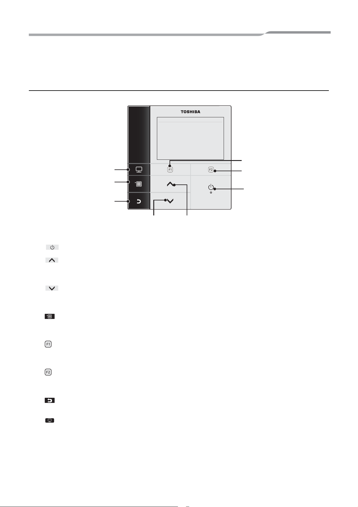
2 Names and functions of parts
Buttons
Owner’s Manual
8
6
4
1
7
23
1 [ ON/OFF] button
2 [ ] button
On the top screen: Adjusts the temperature.
On the menu screen or other screen: Selects a menu item or ON/OFF of each function or moves a cursor, etc.
3 [ ] button
On the top screen: Adjusts the temperature.
On the menu screen or other screen: Selects a menu item or ON/OFF of each function or moves a cursor, etc.
4 [ MENU] button
On the top screen: Displays the MENU screen.
On the other screen: Fixes or copies setting the parameter value.
5 [ ] button
On the top screen: Select the heating or cooling mode.
On the other screen: Varies its function according to the screen.
5-EN
6 [ ] button
On the top screen: Select the hot water mode.
On the other screen: Varies its function according to the screen.
7 [ RETURN] button
Returns to the previous screen, etc.
8 [ MODE] button
On the top screen: Select the mode for which to change the temperature.
On the other screen: Resets the setting parameter value.
– 5 –
Page 7
Hydro Unit
Fig. 2-02
ZONE1 ZONE2 HOT WATER
HEAT/COOL HOT WATER
MON
ZONE1
HEAT/COOL
HEAT/COOL
HOT WATER
HOT WATER
/
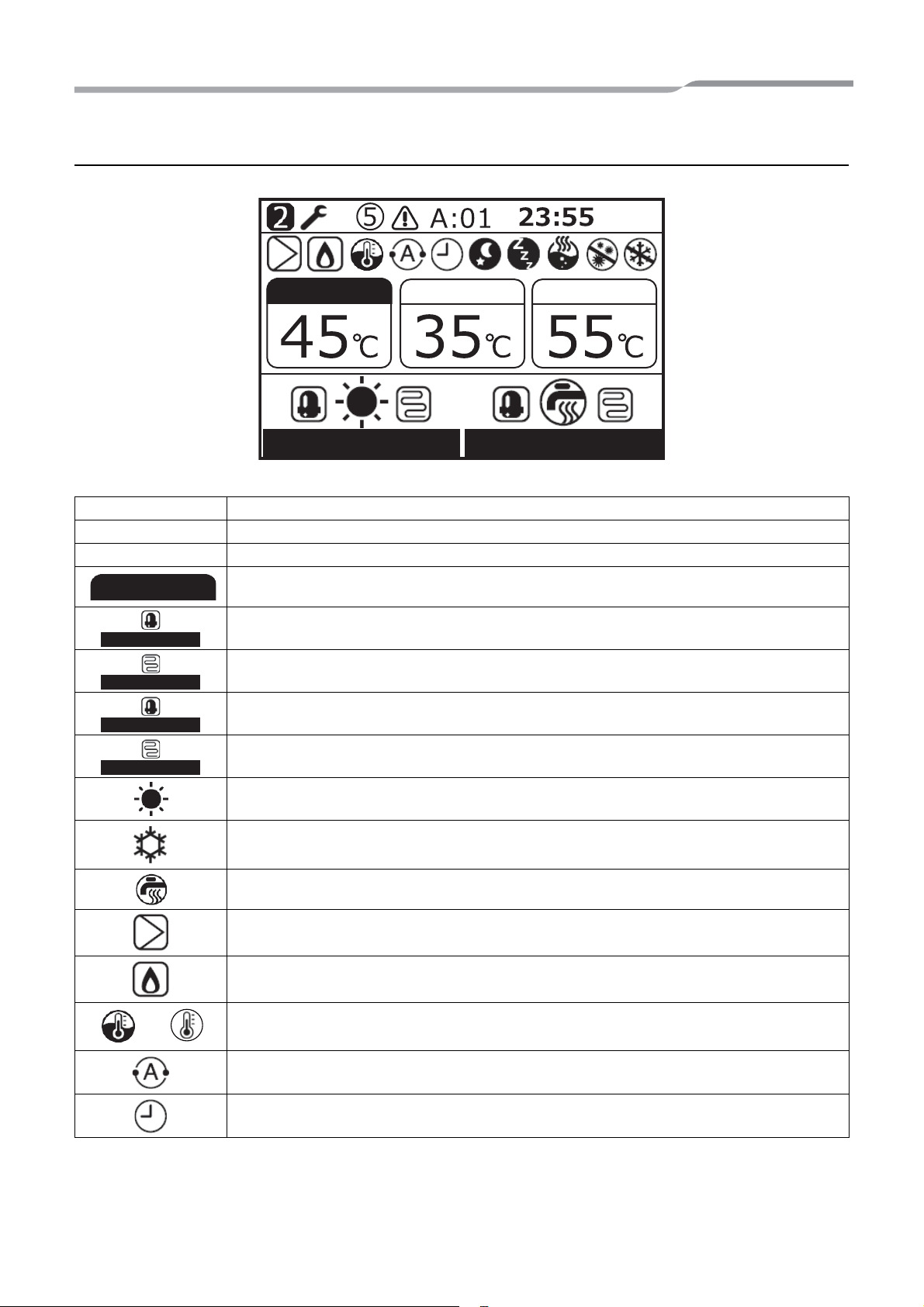
Meaning of Indication on the top screen
ZONE1 Lights when floor heater or radiator is connected (when the system has floor heater or radiator).
ZONE2 Lights when controlling the second temperature (It may not light depending on the system).
HOT WATER Lights when hot water supply system is connected (when the system has hot water supply).
Owner’s Manual
The painted mark lights for operation mode for which temperature is to be changed.
Lights when the compressor is acting for heating or cooling operation.
Lights while the electric heater inside the hydro unit is energized during a heating operation.
Lights while the compressor is acting for hot water supply operation.
Lights while the electric cylinder heater is energized during hot water operation.
Lights when heating is selected.
Lights when cooling is selected.
Lights during hot water supply is selected.
Lights while internal pump (pump 1) or expansion pump (pump 2) is driven.
Lights when the auxiliary boiler or external booster heater supports the heat pump operation.
Lights during water temperature control mode / room temperature control mode.
Lights during Auto mode operation.
Lights when Schedule timer or Floor drying is set to “ON”.
– 6 –
6-EN
Page 8
Hydro Unit
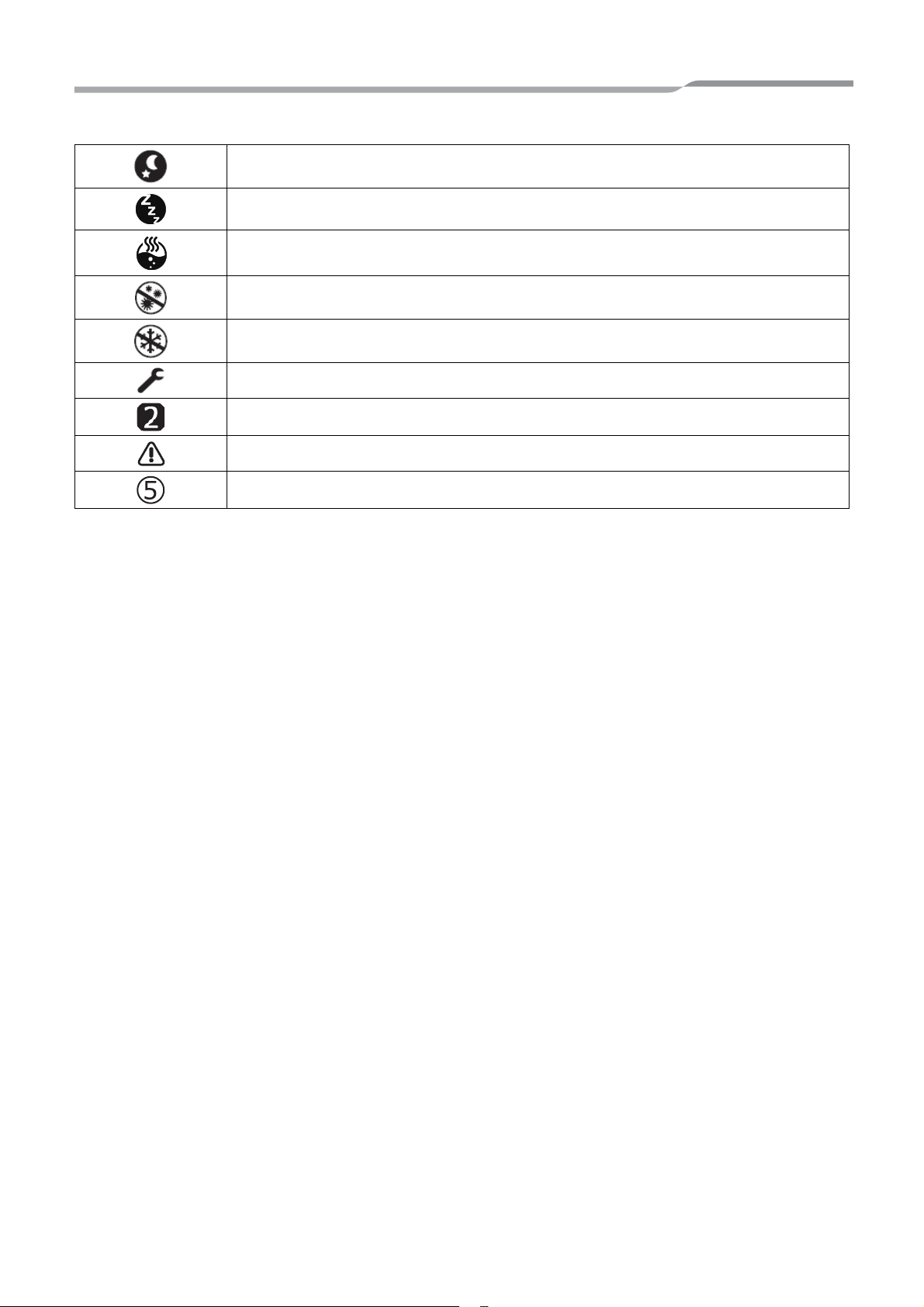
Owner’s Manual
Lights when Night setback operation is set to “ON” and heating or cooling is selected.
Lights while Silent mode operation is actually running.
Lights while hot water boost is actually running.
Lights when Anti bacteria operation is set to “ON” and hot water operation is selected.
Lights while Frost protection operation is actually running.
Lights when Test mode or Floor drying is set to “ON”.
Displays when the remote controller is set as Second remote controller.
Lights when an error occurs and goes out when the error is cleared.
Lights when an error occurs. This number is unit number.
7-EN
– 7 –
Page 9
Hydro Unit
HEAT COOL No indication
(OFF)
ZONE1 ZONE2
HOT WATER
HEAT/COOL
HOT WATER
MON
HOT WATER No indication
(OFF)
ZONE1 ZONE2
HOT WATER
HEAT/COOL HOT WATER
MON
ZONE1 ZONE2
HOT WATER
HEAT/COOL
HOT WATER
MON
3 How to use functions
The following explanation is based on factory setting.
Owner’s Manual
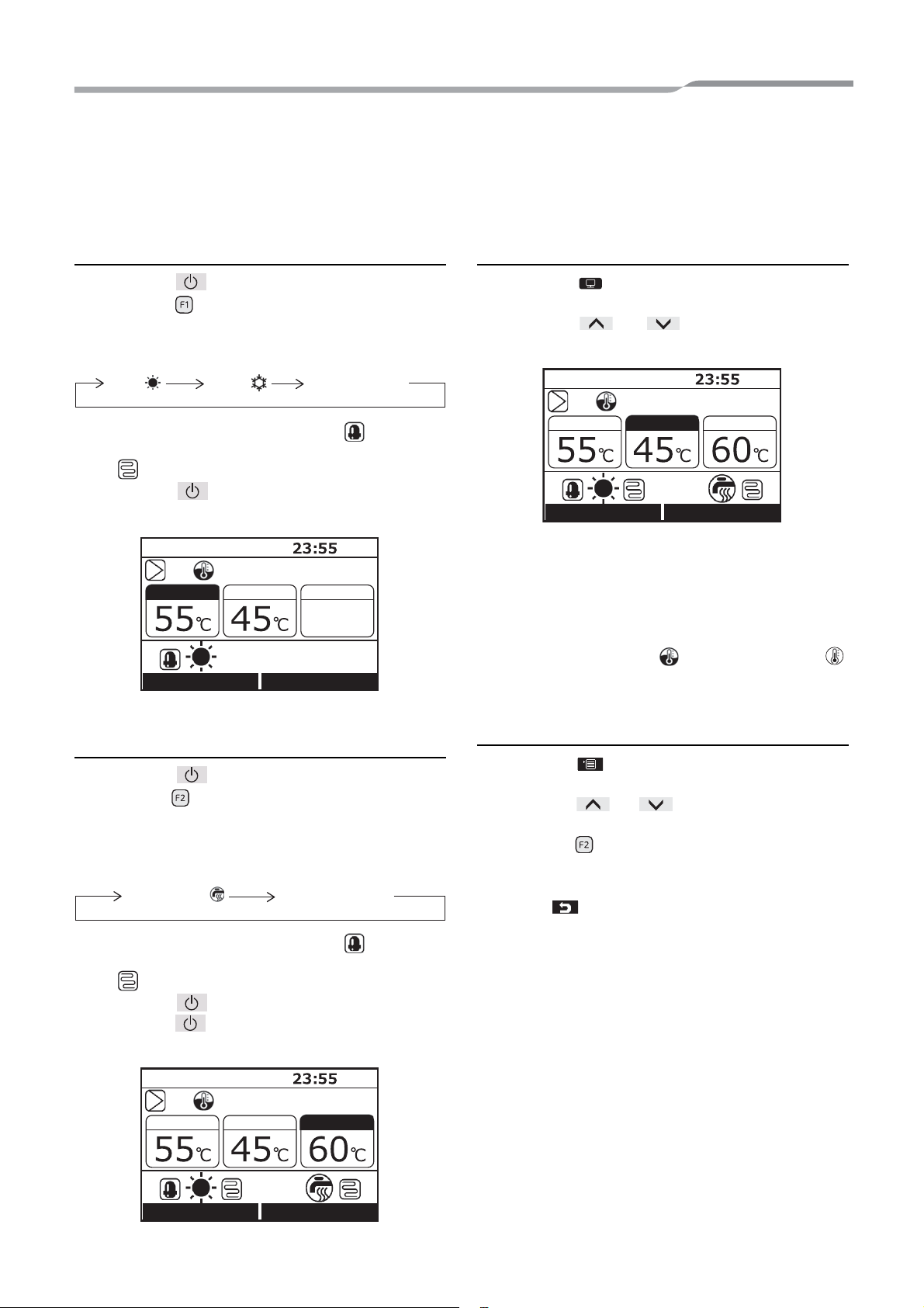
Heating or cooling operation
(1) Press the [ ON/OFF] button to start operation.
(2) Press the [ ] button to select operation mode.
(3) The operation mode changes as follows each time
the button is pressed.
• During the heat pump operation, the mark is
displayed. During the internal heater is energized,
the
(4) When the [ ON/OFF] button is pressed,
mark is displayed.
operation stop.
Changing the temperature
(1) Press the [ ] button to select the mode to
change the temperature.
(2) Press the [ ] / [ ] button to adjust the
temperature.
• The ZONE2 setting temperature must be equal to or
lower than the ZONE1 setting temperature.
• You can choose whether to use water temperature
or room temperature as set temperature.
• When room temperature control is selected with
second remote controller, room temperature is used
as set temperature. The
mark.
mark changes to the
Hot water supply operation
(1) Press the [ ON/OFF] button to start running.
(2) Press the [ ] button to select the Hot water supply
operation mode.
(3) The operation mode changes as follows each time
the button is pressed.
• During the heat pump operation, the mark is
displayed. During the cylinder heater is energized,
the
(4) Press the [ ON/OFF] button to stop running.
mark is displayed.
When the [ ON/OFF] button is pressed, all the
operations, heating or cooling and hot water, stop.
Menu operation
(1) Press the [ ] button, then the menu screen is
displayed.
(2) Press the [ ] / [ ] button to select an item.
The selected item is highlighted.
(3) Press the [ ] button. The setting screen appears.
To undo
Press the [ ] button to return. The display returns to
the previous screen.
– 8 –
8-EN
Page 10

Hydro Unit
MENU
Auto mode
Schedule timer
Night setback
Silent mode
Hot water boost
Anti bacteria
Frost protection
Setting
Initial setting
Schedule setting
Model information
Service information
Information
Clock
Screen contrast
Backlight
Key lock
Header / Second
Temperature control
Language
Condition setting
Holiday setting
... Page 10
... Page 10
... Page 11
... Page 11
... Page 12
... Page 13
... Page 13
... Page 15
... Page 15
... Page 16
... Page 16
... Page 17
... Page 17
... Page 17
... Page 18
... Page 18
... Page 21
... Page 21
... Page 21
... Page 21
... Page 21
Menu items
Owner’s Manual
9-EN
– 9 –
Page 11

Hydro Unit
Fig.3-01
Auto mode
MENU(1/2)
Schedule timer
Night setback
Silent mode
Hot water boost
SET
ON
Auto mode
OFF
FIX
ZONE1 ZONE2
HOT WATER
HEAT/COOL
HOT WATER
MON
Auto mode
FC No. Data
FIX
Auto mode
MENU(1/2)
Schedule timer
Night setback
Silent mode
Hot water boost
SET
ON
Schedule timer
OFF
FIX
Owner’s Manual
Auto mode operation
• The setting temperature can be set automatically
according to the outside temperature.
(1) Press the [ ] / [ ] button to select “Auto
mode” on the MENU screen, then press the [ ]
button.
(2) Press the [ ] button to select “ON” on the Auto
mode screen, then press the [ ] button.
(2) Press the [ ] button to select Data value, then
press the [ ] / [ ] button to adjust the
temperature between -5K to +5 K.
(3) Press the [ ] button. The set temperature is
registered.
Schedule timer
• This function is available only for the header remote
controller.
• Schedule setting makes the following modes to be
flexibly set: hot water supply, heating, cooling, hot
water supply and heating, hot water supply and
cooling, and stop, and set temperature.
• Set the unit clock and the schedule timer setting
before making the setting.
(3) Start the heating operation, then the temperature
indication changes to “A” and the
mark appears
on the top screen.
To shift the Auto curve temperature
• This function is available only for the header remote
controller.
• The set temperature can be shifted in the range of
±5k of the current setting.
(1) Press the [ ] button for 4 seconds or longer on
the Fig.3-01 screen to enter the setting mode. The
function code setting screen appears.
FC No. 27: Shifted temperature
(Range: -5 ~ +5, Default: 0)
(1) Press the [ ] / [ ] button to select
“Schedule timer” on the MENU screen, then press
the [
] button.
(2) Press the [ ] button to select “ON” on the
Schedule timer screen, then press the [ ]
button. The mark appears on the top screen.
– 10 –
10-EN
Page 12

Hydro Unit
Fig.3-02
Auto mode
MENU(1/2)
Schedule timer
Night setback
Silent mode
Hot water boost
SET
ON
Night setback
OFF
FIX
Night setback
FC No. Data
FIX
Auto mode
MENU(1/2)
Schedule timer
Night setback
Silent mode
Hot water boost
SET
Fig.3-03
ON
Silent mode
OFF
FIX
Owner’s Manual
To set the Scheduled operation patterns
• See “Setting -Schedule setting-” (Condition setting
and Holiday setting).
• When setting time comes, the set operation is
started automatically.
Night setback
• This function is used for energy saving during
specified time zone (sleeping hours, etc.).
• For night time hours (sleeping hours, etc.), this
function shifts the set temperature of heating or
cooling by 5k.
(1) Press the [ ] / [ ] button to select an
“Night setback” on the MENU screen, then press
the [
] button.
(3) Press the [ ] button. The set time is registered.
Silent mode
• This function is available only for the header remote
controller.
• This setting is used to reduce noise output, from the
outdoor unit, during night time for neighbours. Night
time low-noise operates with lower operation
frequency and fan tap than normal operation only for
the set time period.
(1) Press the [ ] / [ ] button to select “Silent
mode” on the MENU screen, then press the
[ ] button.
(2) Press the [ ] button to select “ON” on the Night
setback screen, then press the [ ] button.
(3) Start the heating or cooling operation, then the
mark appears on the top screen.
To set Night setback start and end time
• This function is available only for the header remote
controller.
(1) Press the [ ] button for 4 seconds or longer on
the Fig.3-02 screen to enter the setting mode. The
function code setting screen appears.
FC No. 0E: Start time (Range: 0~23, Default: 22)
0F: End time (Range: 0~23, Default: 06)
(2) Press the [ ] / [ ] button to select FC number
or Data, then press the [ ] / [ ]
button to set the value.
The same value cannot be set to 0E and 0F.
(2) Press the [ ] button to select “ON” on the
Silent mode screen, then press the [ ] button.
(3) Start the heating, cooling or hot water operation.
The
mark appears on the top screen during the
set-up time zone.
11-EN
– 11 –
Page 13

Hydro Unit
Silent mode
FC No. Data
FIX
Auto mode
MENU(1/2)
Night setback
Silent mode
Hot water boost
SET
Schedule timer
ON
Hot water boost
OFF
FIX
Owner’s Manual
To set Silent mode start and end time
• This function is available only for the header remote
controller.
(1) Press the [ ] button for 4 seconds or longer on
the Fig.3-03 screen to enter the setting mode. The
function code setting screen appears.
FC No. 0A: Start time (Range: 0~23, Default: 22)
0B: End time (Range: 0~23, Default: 06)
(2) Press the [ ] / [ ] button to select FC number
or Data, then press the [ ] / [ ] button to
set the value.
The same value cannot be set to 0A and 0B.
(3) Press the [ ] button. The set time is registered.
Hot water boost
• This function is used when temporarily giving priority
to the hot water supply operation. The hot water
supply operation is performed in preference to other
operations with a target of the preset time (60
minutes) or the preset temperature (75°C). Use this
function when hot water is not used for a long time or
before using a large amount of hot water.
• The preset time and temperature settings can be
changed to values with in a range of 30 to 180
minutes and 40 to 80°C. Ask the installation
company to make the required changes to the
settings.
• Start the hot water operation before making the
setting.
It may not be able to go to the setting screen
immediately after start. In that case, select “Hot
water boost” again after tens of seconds.
(1) Press the [ ] / [ ] button to select “Hot
water boost” on the MENU screen, then press the
[ ] button.
(2) Press the [ ] button to select “ON” on the Hot
water boost screen, then press the [ ] button.
The mark appears on the top screen.
• When the set time period has passed or the water
temperature has reached the set temperature, the
hot water boost operation ends automatically.
– 12 –
12-EN
Page 14

Hydro Unit
Fig.3-04
Anti bacteria
MENU(2/2)
Frost protection
Setting
Information
SET
ON
Anti bacteria
OFF
FIX
Anti bacteria
FC No. Data
FIX
MENU(2/2)
Frost protection
Setting
Information
SET
Anti bacteria
Fig.3-05
ON
Frost protection
OFF
FIX
Owner’s Manual
Anti bacteria
• This setting regularly raises the hot water cylinder
temperature to prevent bacteria from growing.
• The anti-bacteria operation is performed to maintain
the temperature (75°C) for the period (30
when the preset start time (22:00) comes according
to the preset cycle (7 days).
• The maintain temperature and the period can be
changed, ask the installation company to make the
required changes to the settings.
(1) Press the [ ] / [ ] button to select “Anti
bacteria” on the MENU screen, then press the
[ ] button.
(2) Press the [ ] button to select “ON” on the Anti
bacteria screen, then press the [ ] button.
minutes)
(3) Press the [ ] button. The set value is registered.
Frost protection
• This function performs operation with the minimum
capacity (target water temperature:15°C) to prevent
pipes from freezing in case the unit is not used for a
long period due to absence.
• Cancel schedule timer to start frost protection
operation. When frost protection is operated with
schedule timer on, it may stop during its operation.
• The minimum capacity can be changed, ask the
installation company to make the required changes
to the settings.
• This function takes precedence over the Night
setback operation that is set separately.
• Start the heating operation before making the
setting.
It may not be able to go to the setting screen
immediately after start. In that case, select “Frost
protection” again after tens of seconds.
(3) Start the hot water operation, then the mark
appears on the top screen.
To set Anti bacteria maintain temperature and start
time
• This function is available only for the header remote
controller.
(1) Press the [ ] button for 4 seconds or longer on
the Fig.3-04 screen to enter the setting mode. The
function code setting screen appears.
FC No. 0C: Start time (Range: 0~23, Default: 22)
0D: cycle (Range: 0~10, Default: 07)
(2) Press the [ ] / [ ] button to select FC number
or Data, then press the [ ] / [ ] button to
set the value.
(1) Press the [ ] / [ ] button to select “Frost
protection” on the MENU screen, then press the
[ ] button.
(2) Press the [ ] button to select “ON” on the Frost
protection screen, then press the [ ] button.
13-EN
– 13 –
Page 15

Hydro Unit
ZONE1 HOT WATER
HEAT/COOL
HOT WATER
MON
Frost protection
FC No. Data
FIX
Owner’s Manual
(3) The temperature indication change to “F” and
mark appears on the top screen.
• When the set period has passed, the Frost protection
operation ends automatically.
To set the end days and time for the frost
protection operation
• This function is available only for the header remote
controller.
(1) Press the [ ] button for 4 seconds or longer on
the Fig.3-05 screen to enter the setting mode. The
function code setting screen appears.
FC No. 12: End days (Range: 0~20, Default: 0)
13: End times (Range: 0~23, Default: 0)
ex)
Code No. 12: 05
13: 13 = 5 days 13 hours
(2) Press the [ ] / [ ] button to select FC number
or Data, then press the [ ] / [ ] button to
set the value.
(3) Press the [ ] button. The set value is registered.
– 14 –
14-EN
Page 16

Hydro Unit
Anti bacteria
MENU(2/2)
Frost protection
Setting
Information
SET
Initial setting
Setting
Schedule setting
SET
Clock
Initial setting(1/2)
Screen contrast
Backlight
Header / Second
SET
Temperature control
←
→
31 / 12 / 2016 01:11
Clock
FIX
Owner’s Manual
Setting – Initial setting –
(1) Press the [ ] / [ ] button to select
“Setting” on the MENU screen, then press the [ ]
button.
(2) Press the [ ] / [ ] button to select “Initial
setting” on the Setting screen, then press the [ ]
button.
Clock
• Setting for the clock (date, month, year, time)
(1) Press the [ ] / [ ] button to select “Clock”
on the Initial setting screen, then press the [ ]
button.
(2) Press the [ ] / [ ] button to select the date,
month, year, and, time.
(3) Press the [ ] / [ ] button to set the value,
then press the [ ] button.
15-EN
• The clock display appears on the top screen.
• The clock display blinks if the clock setting has been
reset due to power failure or other cause.
– 15 –
Page 17

Hydro Unit
Clock
Initial setting(1/2)
Screen contrast
Backlight
Header / Second
SET
Temperature control
Screen contrast
FIX
Clock
Initial setting(1/2)
Screen contrast
Backlight
Header / Second
SET
Temperature control
ON
Backlight
OFF
FIX
Owner’s Manual
Screen contrast
• Contrast adjustment of the LCD
(1) Press the [ ] / [ ] button to select “Screen
contrast” on the Initial setting screen, then press the
[
] button.
(2) Press the [ ] / [ ] button to adjust, then
press the [ ] button.
(2) Press the [ ] / [ ] button to select
ON/OFF, then press the [ ] button.
• The back light of the LCD is turned on as factory
default.
• The back light is on for about 30 seconds after button
operation.
Backlight
• Turn on or off the backlight of the LCD
(1) Press the [ ] / [ ] button to select
“Backlight” on the Initial setting screen, then press
the [
] button.
– 16 –
16-EN
Page 18

Hydro Unit
Clock
Initial setting(1/2)
Screen contrast
Backlight
Header / Second
SET
Temperature control
Header
Header / Second
Second
FIX
Initial setting(2/2)
Language
SET
Language(1/2)
English
Turkish
French
German
Spanish
FIX
Türkçe
Français
Deutsch
Español
Language(2/2)
Italian
FIX
Italiano
Owner’s Manual
Header / Second
• For a dual remote controller system.
• Set one of remote controller as the header remote
controller.
• Set another remote controller as the second remote
controller.
(1) Press the [ ] / [ ] button to select
“Header / Second” on the Initial setting screen,
then press the [ ] button.
(2) Press the [ ] / [ ] button to select
Header / Second, then press the [ ] button.
Temperature control
• To control room temperature instead of water
temperature with this remote controller.
Please check with the installer for details.
Language
• Select a language for the screen text.
(1) Press the [ ] / [ ] button to select
“Language” on the Initial setting screen, then press
the [
] button.
(2) Press the [ ] / [ ] button to select
the language, then press the [ ] button.
17-EN
• Some function are not available when the remote
controller is set as the “Second remote controller”.
• In the dual remote controller system, the latter
operation overrides the former.
• The factory default is “Header remote controller”.
Disable function with second remote controller
•Schedule timer
•Silent mode
•Schedule setting
• The factory default is “English”.
– 17 –
Page 19

Hydro Unit
Anti bacteria
MENU(2/2)
Frost protection
Setting
Information
SET
Initial setting
Setting
Schedule setting
SET
Condition setting
Schedule setting
Holiday setting
SET
Key lock
-- -- - - - - - - : - - -- : --
-- -- - - - - - - : - - -- : --
-- -- - - - - - - : - - -- : --
Condition setting(1/2)
ALL
MON
TUE WED THU FRI SAT SUN
Mode Start End
SETDAY
COPY
RESET
Z1 Z2 HW
Condition setting(1/2)
ALL TUE WED THU FRI SAT SUN
Mode Start End
FIX RESET
Z2 HWZ1
COOL
HW
MON
HEAT
Schedule timer confirm?
Condition setting
NOYES
Owner’s Manual
Setting – Schedule setting –
• This function is available only for the header remote
controller.
(1) Press the [ ] / [ ] button to select
“Setting” on the MENU screen, then press the [ ]
button.
(2) Press the [ ] / [ ] button to select
“Schedule setting” on the setting screen, then press
the [
] button.
(2) Press the [ ] button to select the day, then press
the [ ] button to input running pattern.
(3) Press [ ] / [ ] button to select the change item,
then press the [ ] / [ ] button.
55 45 - - 08:00 22:00
25 - - - - 23:00 - - : - -
- - - - 65 18:00 19: 00
(4) Press the [ ] button.
Condition setting
• Up to 6 different running patterns per day can be
programmed.
(1) Press the [ ] / [ ] button to select
“Condition setting” on the Schedule setting screen,
then press the [
] button.
(5) Press the [ ] button to Fix.
Mode : Operation mode (HEAT, COOL, HW (Hot
water))
Z1 : ZONE1 setting temperature
Z2 : ZONE2 setting temperature
HW : Hot water supply operation setting
temperature
Start : Operation start time (0:00 ~ 23:59)
End : Operation end time (0:00 ~ 24:00, -- : --)
• “-- : --” means the operation continues.
If End time is set earlier than Start time, an error is
displayed.
– 18 –
18-EN
Page 20

Hydro Unit
20:00
AB
24:00
00:00
6:00
Time
Start End
Monday Tuesday
< Hot water supply operation >
--
--
- - - -
20:00 24:0065
Condition setting(1/2)
ALL
MON
TUE WED THU FRI SAT SUN
Mode Start End
SETDAY
COPY
RESET
Z1 Z2 HW
HW
A
Condition setting(1/2)
ALL WED THU FRI SAT SUN
Mode Start End
SETDAY
COPY
RESET
Z1 Z2 HW
HW
B
MON TUE
Condition setting(1/2)
TUE WED THU FRI SAT SUN
Mode Start End
SETDAY
RESET
Z1 Z2 HW
HW
HW
MONALL
MON TUE WED FRI SAT SUN
SETDAY
THU
FIX
Holiday setting
Owner’s Manual
Easy method of setting up ranging over a day in Schedule operation
There are two methods.
If “24:00” is set to “End” and “00:00” is set to “Start” next day, the previous operation status will be continued.
And set the time you want to stop to “End”.
If “--” is set to “End”, the previous operation status will be continued next day. And set the time you want to stop
to “End”. Any “Start” time is sufficient if it is earlier than “End” time.
For example) * In the case of the setting method
How to set up Hot water supply operation from 20:00 of Monday night to 6:00 of Tuesday morning.
When a day of the week is specified.
-1
Set individually about Monday and Tuesday.
When use the ALL setting.
-2
If you want to set up two or more days, you can set up
easily using the function.
Set about ALL, then it will be similarly set up from
Monday to Sunday.
--
--
--
- - - -
- - - -
- - - -
00:00 06:0065
20:00 24:0065
00:00 06:0065
If there are some days you don’t want to do Schedule
operation, do Holiday setting after that.
19-EN
– 19 –
Page 21

Hydro Unit
-- -- - - - - - - : - - -- : --
-- -- - - - - - - : - - -- : --
-- -- - - - - - - : - - -- : --
Condition setting(1/2)
ALL MON WED THU FRI SAT SUN
Mode Start End
SET
DAY
COPY RESET
Z1 Z2 HW
TUE
Copy the previous day setting?
Condition setting
NOYES
↓
55 45 - - 08:00 22:00
25 - - - - 23:00 - - : - -
- - - - 65 18:00 19: 00
Condition setting(1/2)
ALL MON WED THU FRI SAT SUN
Mode Start End
COPY
RESET
Z2
HW
Z1
COOL
HEAT
TUE
HW
SET
DAY
Condition setting(1/2)
ALL MON WED THU FRI SAT SUN
Mode Start End
COPY RESET
Z2
HW
Z1
COOL
HEAT
TUE
HW
SET
DAY
Delete the day setting?
Condition setting
NOYES
↓
-- -- - - - - - - : - - -- : --
-- -- - - - - - - : - - -- : --
-- -- - - - - - - : - - -- : --
Condition setting(1/2)
ALL MON WED THU FRI SUN
Mode Start End
SET
DAY
COPY RESET
Z1 Z2 HW
TUE
SAT
Owner’s Manual
To copy the settings of the previous day
(1) Press the [ ] button to select the day, then press
the [ ] button to copy the settings of the previous
day.
(2) Press the [ ] button, then the contents of the
setting is displayed.
To reset the settings for each day.
(1) Press the [ ] button to select the day, then press
the [ ] button to reset the settings of the day.
55 45 - - 08:00 22:00
25 - - - - 23:00 - - : - -
- - - - 65 18:00 19: 00
(2) Press the [ ] button, then the contents of the
setting is cleared.
•If the [ ] button is pressed in the state where
“MON” is selected, the contents of the setting of
“SUN” is copied.
– 20 –
20-EN
Page 22

Hydro Unit
Condition setting
Schedule setting
Holiday setting
SET
Key lock
MON TUE WED FRI SAT SUN
SETDAY
THU
FIX
Holiday setting
ON/OFF
Key lock
FIX
Temp. Mode
SELECT
LOCK
Anti bacteria
MENU(2/2)
Frost protection
SET
Information
Setting
Information
Model information
Service information
SET
Model information
Information
Service information
SET
Owner’s Manual
Holiday setting
• Set the days of the week when the schedule timer
not used.
(1) Press the [ ] / [ ] button to select “Holiday
setting” on the Schedule setting screen, then press
the [
] button.
(2) Press the [ ] button to select the day, then press
the [ ] button to set.
: Schedule timer is not used.
●
Information
(1) Press the [ ] / [ ] button to select
“Information” on the MENU screen, then press the
[ ] button.
Model Information
• Shows the model names and serial numbers.
(1) Press the [ ] / [ ] button to select “Model
information” on the Information screen, then press
the [
] button.
(3) Press the [ ] button to Fix.
Key lock
• Select whether to LOCK / UNLOCK [ON/OFF],
[Temperature], [mode] during schedule timer.
(1) Press the [ ] / [ ] button to select “Key
lock” on the Schedule setting screen, then press the
[ ] button.
(2) Press the [ ] button to select object, then press
the [ ] button to select LOCK or UNLOCK.
: LOCK
●
(3) Press the [ ] button to Fix.
• When “LOCK” is selected, the key cannot be used
during Key lock and schedule timer.
• The factory default is “UNLOCK”.
Service information
• Shows the contact number for service.
(1) Press the [ ] / [ ] button to select “Service
information” on the Information screen, then press
the [
] button.
21-EN
– 21 –
Page 23

Hydro Unit
Owner’s Manual
4 User maintenance
Periodic maintenance (once a year) is necessary for this product. Consult the installation company.
If a problem occurs, contact the installation company or dealer.
5 Air to Water Heat Pump operations and
performance
3 minutes protection function
3 minutes protection function prevents the air to water heat pump from starting for initial 3 minutes after the main
power switch/circuit breaker is turned on for re-starting the air to water heat pump.
Power failure
Power failure during operation will stop the unit completely.
• To restart the operation, we should mention Auto restart function.
Heating characteristics
Defrosting operation
If the outdoor unit is frosted during the heating or hot water supply operation, defrosting starts automatically (for
approximately 2 to 10 minutes) to maintain the heating capacity.
• During the defrosting operation, the defrosted water will be drained from the bottom plate of the outdoor unit.
Heating capacity
In the heating operation, the heat is absorbed from the outside and brought into the room. This way of heating is
called heat pump system. When the outside temperature is too low, it is recommended to use another heating
apparatus in combination with the air to water heat pump.
Attention to snowfall and freeze on the outdoor unit
• In snowy areas, the air intake and air discharge of the outdoor unit are often covered with snow or frozen up.
If snow or freeze on the outdoor unit is left as it is, it may cause machine failure or poor warming.
• In cold areas, pay attention to the drain hose so that it perfectly drains water without water remaining inside for
freeze prevention. If water freezes in the drain hose or inside the outdoor unit, it may cause machine failure or
poor warming.
Air to water heat pump operating conditions
For proper performance, operate the air to water heat pump under the following temperature conditions:
Cooling operation
Hot water
Heating operation
Outdoor temperature : 10°C to 43°C
Room temperature : 18°C to 32°C (Dry bulb temp.)
Outdoor temperature : -20°C to 43°C (Heater operation in more than 35°C)
Room temperature : 5°C to 32°C
Outdoor temperature : -20°C to 25°C
Room temperature : 5°C to 32°C
If air to water heat pump is used outside of the above conditions, safety protection may work.
– 22 –
22-EN
Page 24

Hydro Unit
Owner’s Manual
General Specifications
Outdoor Unit
Single Phase model
Outdoor unit HWS-455H-E HWS-805H-E HWS-1105H-E HWS-1405H-E
Power supply 220-230 V ~ 50 Hz
Type INVERTER
Function Heating & Cooling
Capacity (kW) 4.5 8.0 11.2 14.0
Heating
Cooling
Refrigerant R410A
Dimension HxWxD (mm) 630x800x300 890x900x320 1,340x900x320
3 Phase model
Power supply 380-400 V 3N~ 50 Hz
Type INVERTER
Function Heating & Cooling
Heating
Cooling
Refrigerant R410A
Dimension HxWxD (mm) 1,340x900x320
Cord heater (W) – 75
Input (kW) 0.92 1.79 2.30 3.11
COP (W/W) 4.90 4.46 4.88 4.50
Capacity (kW) 4.5 6.0 10.0 11.0
Input (kW) 1.46 1.94 3.26 3.81
EER (W/W) 3.08 3.10 3.07 2.89
with Cord heater
Outdoor unit
Capacity (kW) 11.2 14.0 16.0 11.2 14.0 16.0
Input (kW) 2.34 3.16 3.72 2.34 3.16 3.72
COP 4.80 4.44 4.30 4.80 4.44 4.30
Capacity (kW) 10.0 11.0 13.0 10.0 11.0 13.0
Input (kW) 3.26 3.81 4.80 3.26 3.81 4.80
EER 3.07 2.89 2.71 3.07 2.89 2.71
HWS-
1105H8-E
HWS-
1405H8-E
HWS-
1605H8-E
HWS-
1105H8R-E
HWS-
1405H8R-E
HWS-
1605H8R-E
23-EN
– 23 –
Page 25

Hydro Unit
Owner’s Manual
Hydro Unit (4.5 kW model)
Hydro Unit HWS-455XWHM3-E
Back up heater capacity (kW) 3.0
for back up heater 220-230 V ~ 50 Hz
Power supply
Leaving water
temperature
for hot water cylinder heater
(option)
Heating (°C) 20-55
Cooling (°C) 7-25
220-230 V ~ 50 Hz
Hydro Unit (8 kW model)
Hydro Unit HWS-805XWHM3-E HWS-805XWHT6-E HWS-805XWHT9-E
Back up heater capacity (kW) 3.0 6.0 9.0
for back up heater 220-230 V~ 50 Hz 380-400 V 3N~ 50 Hz 380-400 V 3N~ 50 Hz
Power supply
Leaving water
temperature
for hot water cylinder heater
(option)
Heating (°C) 20-55
Cooling (°C) 7-25
220-230 V~ 50 Hz
Hydro Unit (11 kW, 14 kW, 16 kW model)
Hydro Unit HWS-1405XWHM3-E HWS-1405XWHT6-E HWS-1405XWHT9-E
Back up heater capacity (kW) 3.0 6.0 9.0
for back up heater 220-230 V~ 50 Hz 380-400 V 3N~ 50 Hz 380-400 V 3N~ 50 Hz
Power supply
Leaving water
temperature
for hot water cylinder heater
(option)
Heating (°C) 20-55
Cooling (°C) 7-25
220-230 V~ 50 Hz
Hot water cylinder (option)
Hot water cylinder (option)
Power supply 220-230 V~ 50 Hz
Water volume (liter) 150 210 300
Max water temperature (°C) 75
Electric heater (kW) 2.7
Height (mm) 1,090 1,474 2,040
Diameter (mm) 550
Material Stainless steel
HWS-1501CSHM3-E
HWS-1501CSHM3-UK
HWS-2101CSHM3-E
HWS-2101CSHM3-UK
HWS-3001CSHM3-E
HWS-3001CSHM3-UK
– 24 –
24-EN
Page 26

Hydro Unit
6 Troubleshooting
If a problem occurs, contact the installation company or dealer.
Problem Check Action
Nothing is displayed on the remote controller.
Time indication is blinking.
An error code is displayed on the remote
controller.
Room is not cooled or heated.
Hot water is not supplied.
• Check whether power is supplied.
• Is the circuit breaker switch turned on?
• Date/time setting is not made.
• Set date and time.
• Contact the installation company.
• Is scheduled operation set?
• Check whether scheduled operation is set.
• Is night setback operation set?
• Check the setting on the remote controller.
• Is the air to water heat pump operating in Auto mode?
• In Auto mode, the target value is set automatically according to the
outdoor unit temperature.
• The Auto mode can be adjusted. Contact the installation company.
• Is the main water supply cock closed?
• Check valves.
• Are you using too much hot water?
• If hot water exceeding the storage capacity is used, water at a
temperature lower than the set hot water temperature is supplied.
Owner’s Manual
If you have any questions, contact the installation company.
25-EN
– 25 –
Page 27

Hydro Unit
Owner’s Manual
– 26 –
Page 28

EF99911001-1
 Loading...