

Page 1

INTRODUCTION
STARTUP GUIDANCE
9
17
HDD-J35
OWNER'S MANUAL
RECEIVING
RECORDING
PLAYBACK
31
55
61
©2005 Toshiba Corporation
APPENDICES
DVB registration identification reference number: 3253.
Trade Mark of the DVB Digital Video Broadcasting Project
(1991 to 1996)
67
Page 2

PRECAUTIONS
g
p
WARNING: TO PREVENT FIRE OR SHOCK HAZARD, DO NOT EXPOSE THIS APPLIANCE TO RAIN OR
MOISTURE.
TO PREVENT ELECTRIC SHOCK, DO NOT OPEN THE COVER. REFER SERVICING TO
QUALIFIED PERSONNEL ONLY.
This unit is not disconnected from the AC power source as long as it is connected to the wall outlet, even if the
unit itself is in standby mode.
NOTE
The rating label and the safety caution are on the rear of the unit.
Chan
es or modifications to this equipment not expressly authorised or approved by Toshiba could void the
product warranty and/or cause damage to the product.
In order to continue to get the maximum performance from your recorder:
• Make sure that it is set up properly.
• Have it regularly inspected by qualified service personnel.
• Make sure that all family members learn to operate it properly.
In particular: To prevent electric shock, instruct children not to insert objects into the recorder’s holes or slots.
POWER CORD CAUTIONS
• When plugging in or unplugging the power cord, hold it by the plug. Do not unplug it by pulling on the cord.
• Do not touch the cord with wet hands as this could cause electrical shock or short.
• Do not place furniture, etc., on top of the power cord.
• Do not tie up the power cord, or connect a different power cord.
• Route the power cord so that it is not stepped on, or tripped over.
• Using a damaged power cord could result in fire or electric shock. Ins
damaged, consult your nearest TOSHIBA service centre.
ect the power cord for damage. If
SAFETY MEASURES ON PROPER USAGE
Pay attention to the following items when using this unit. Failure to do so may result in electric shock or damage
to the unit.
1. Connect the power plug to AC 100-240V 50/60Hz.
2. Unplug the power cord from the recorder before connecting any other equipment, especially the TV
antenna. Connect all equipment to the recorder before plugging any power cords to the power source.
3. Be sure your TV antenna is not located near overhead power lines, or where it might fall into any power
lines. Also be careful to avoid touching any such power lines when installing the TV antenna.
4. Do not attempt to modify the unit.
5. If you hear a strange sound or notice smoke coming from the unit or feel that the unit is too hot to touch,
turn the power off immediately, unplug the power cord, and consult with your local sales outlet.
6. Do not insert metal objects, paper or liquids into the unit through the ventilation openings, etc. This could
result in fire or electric shock. In the event something is inserted inside, turn the power off, unplug the
power cord and consult your local sales outlet.
7. Do not place objects that may block the ventilation openings of the unit such as a piece of cloth.
8. Do not place vases, bottles, containers, naked flame sources such as lighted candles etc., on top of or
near this unit.
9. When transporting, do not vibrate or shake the unit. This may result in damage or faulty operation.
10. If a three-prong power plug is provided with recorder, be sure it is used with a properly grounded threewise power socket.
11. When transporting the unit, be sure to turn off the power and disconnect all cables.
12. When not using the unit for a long period of time (when on vacation, etc.) unplug the power cord.
13. Avoid overloading electrical outlets or extension cords otherwise it could result in electric shock or fire.
14. When lightning begins, do not touch any part of the recorder including the power cord and any
connected cables.
2
Page 3
DO NOT use or place the recorder in the following environments:
p
1. Near heat sources
• Places subject to direct sunlight
• Near radiators or air ducts
• On top of an amplifier
2. Dusty places
3. Places subject to vibration or shock
4. Near strong magnetic fields such as loudspeakers or large motors
5. Places subject to moisture such as a kitchen or bathroom
6. Places without adequate air circulation
• On top of a carpet or sofa
• In a bookcase
• Near materials such as curtains, etc.
7. Extremely hot or cold places
The operating temperature range of this unit is 5°C to 40°C
MOISTURE CONDENSATION
Never operate this recorder immediately after moving it from a cold location to a warm location. After moving,
leave the recorder in the warm location for TWO TO THREE hours without o
condensation naturally.
Moisture condensation is most likely to occur in the following cases:
• When moved from a cold location to a warm location.
• In a room rapidly heated or in a place where the recorder is directly exposed to cool flow of air from an air-
conditioner or other electrical appliance.
• In a room with excessive dampness or high humidity.
erating it so as to dry the moisture
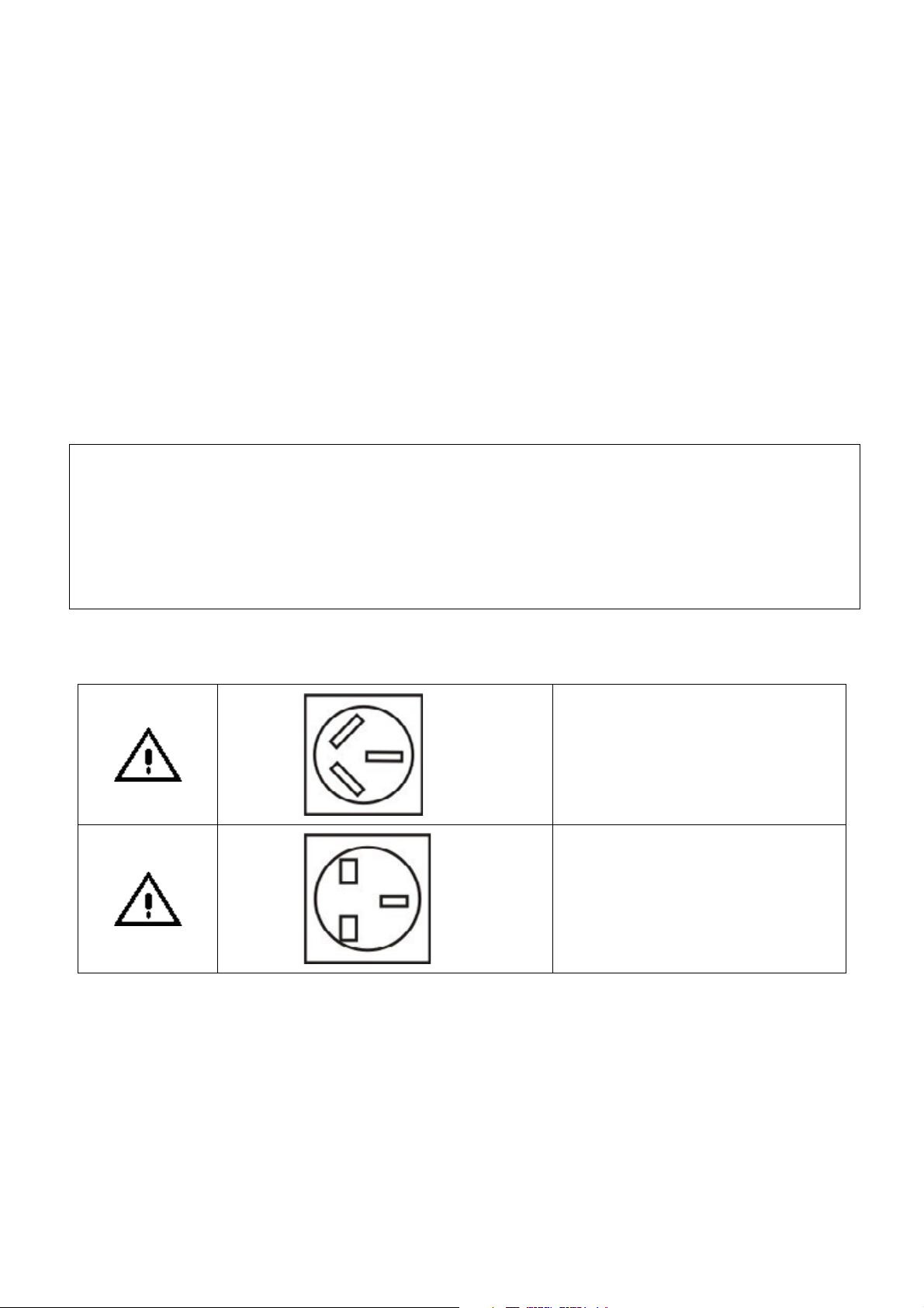
NOTES ON POWER PLUGS
•
The diagrams above are strictly for illustration purposes only.
•
Only one power plug is included in the recorder’s accessory box (page 76).
This power plug is used in Australia
only
This power plug is used in some other
regions
3
Page 4

ABOUT THE HARD DISK DRIVE (HDD)
Like any HDD, the HDD in the recorder is a fragile device that is susceptible to partial or complete failure if it is
jarred or as a result of use over time. It will not last forever. Therefore, do not use the HDD for long-term storage
of the programs you wish to retain. (If portions of the HDD become damaged, programs recorded on those
portions may exhibit pixelisation or blocked noise when played back. Repeated playback of the program may
cause the problem to get worse and, eventually the program may become unplayable. If you noticed such noise
in a program that you want to save, you should archive the program using a VCR as soon as possible and delete
the affected program.) A periodical cleanup of the HDD is advisable by doing a Format Hard Disk. Refer to page
36.
If it becomes necessary to service your recorder, it may be necessary to delete some or all of the programs on
the HDD.
Using the recorder outside the operating temperature range (5ºC ~ 40ºC) may cause the HDD to be nonfunctional (even when the recorder is powered on) or to display with error status. Use this recorder only within
the operating temperature.
The internal HDD has a limited life span that is dependent on the frequency of usage. Extremely heavy usage
shortens the life span and causes the HDD to function abnormally. When all the recorded programs start to show
noise in the display, it may be time to replace the HDD. Consult your local dealer for replacement of HDD.
If you see no signs of activity in the HDD during recording or playback, stop using the recorder and remove the
power plug from the wall socket immediately. Consult the local dealer for service. Ignoring this condition may
cause the damage of the HDD to be aggravated.
NOTES ON RECORDING
•
When you record important contents, make trial operations beforehand to ensure the recorder can function
properly.
Toshiba does not compensate for content that was not recorded because of some malfunction of this
product during operation, and is not liable for incidental damages (such as profit loss or interruption of
business, etc.) produced in such conditions.
•
When the power cord is disconnected or when a power failure occurs during any operation of this product,
all contents recorded in this recorder may be erased.
•
If a program you have set a timer recording includes copy restriction signals, it may not be recorded. When
programming a recording, confirm that the program you want to record is not copy-restricted.
NOTES ON COPYRIGHT
•
It is forbidden by law to copy, broadcast, show, broadcast on cable and play in public copyrighted material
without permission.
•
This product incorporates copyright protection technology related to A/V media, that is designed to prevent
copying and hence upon the detection of such signal, the display may be prohibited. This applies to timer
recording as well.
•
This product incorporates copyright protection technology that is protected by method claims of certain U.S.
patents and other intellectual property rights owned by Macrovision Corporation and other rights owners.
Use of this copyright protection technology must be authorized by Macrovision Corporation, and is intended
for home and other limited viewing uses only unless otherwise authorized by Macrovision Corporation.
Reverse engineering or disassembly is prohibited.
4
Page 5

NOTES ON HANDLING
•
This unit contains an internal HDD, which is susceptible to surrounding environmental changes such as
shock, vibration and temperature. Take note of the following points to avoid loss of recorded content:
1. Do not apply shock or vibration to the unit.
2. Do not use the unit on a shaky or unstable place.
3. Do not install the unit on a non-flat surface.
4. Do not cover up the ventilation holes of the unit.
5. Do not use the unit in a high temperature environment or environment with extreme changes in
temperature.
6. Unless in an emergency, do not remove the power plug from the wall socket while HDD access
(read/write) is in progress (as indicated by the Front Panel display). This may result in loss of recorded
data.
7. Toshiba is not liable to any damage or loss of recorded data due to shock, vibration and misuse.
8. Never remove the top cover, disassemble or modify the unit. These actions may cause the recorded
data to be destroyed. Moreover, removing the top cover voids the warranty even if the product is within
the warranty period.
•
When the unit is in use, sounds due to the internal HDD disk movement, sometimes even during standby
mode. This is not a malfunction.
•
When moving the unit to a remote location, cover the unit with a piece of cloth to prevent injury. Also, take
care not to shake or apply shock to the unit.
•
The top cover or rear panel may become warm after operating for a long time. This is not a malfunction.
•
Do not use insecticide sprays, etc., near the unit. Also, do not leave rubber or plastic objects in contact with
the unit for long periods of time. This may cause discoloring of this unit’s finish.
•
Keep the original packing that this unit came in and use it to re-pack the unit when moving or transporting.
ABOUT CLEANING
•
Do not use solvents such as benzene, alcohol or thinner to clean the unit. These solvents may distort the
chassis or damage its finish. If rubber or vinyl products remain in contact with the unit for a long time, a stain
may result.
•
When the unit becomes dirty, clean it gently with a piece of soft, dry cloth.
•
When the unit is very dirty, remove the power plug from the wall socket and use a piece of damp cloth to
wipe the unit clean. Finish the cleaning with a piece of dry cloth.
DISCLAIMER
This manual has been validated and reviewed for accuracy. The instructions and descriptions it contains are
accurate for the HDD-J35 recorder at the time of this manual’s production. However, succeeding units and
manuals are subject to change without notice. Toshiba assumes no liability for damages incurred directly or
indirectly from errors, omissions or discrepancies between the recorder and the manual.
Toshiba is not liable for loss of recorded content caused by malfunction or damage of the internal HDD, and is
not liable for incidental damages (such as profit loss of interruption of business, etc.) produced in such
conditions.
5
Page 6

Exemptions
y
g
Toshiba is not liable for any damage caused by fire, natural disaster (such as thunder, earthquake, etc.)
acts by third parties, accidents, misuse, or uses in other improper conditions.
Toshiba is not liable for incidental damages (such as profit loss or interruption in business, modification or
erasure of record data, etc.) caused by use or inability to use of this product.
Toshiba is not liable for any damage caused by neglect of the instructions described in the owner’s manual.
Toshiba is not liable for any damage caused by misuse or malfunction through simultaneous use of this
product and the connected equipment.
Thank you very much for purchasing this Toshiba Digital HD Receiver and HDD Recorder HDD-J35.
In order to enjoy the many features this recorder has to offer, read this owner’s manual thoroughly before using.
We hope that you are completely satisfied with
ive you long and enjoyable service. We look forward to providing you with additional Toshiba products to serve
all of your entertainment needs in the future.
In the space provided below, record the Serial Number located on the rear panel of your recorder.
Model No. HDD-J35 Serial No.
Retain this information for future reference.
our Toshiba Digital HD Receiver and HDD recorder and it will
6
Page 7

TABLE OF CONTENTS
PRECAUTIONS ....................................................................................................................................................... 2
CHAPTER ONE ....................................................................................................................................................... 9
INTRODUCTION ..................................................................................................................................................... 9
IDENTIFICATION OF CONTROLS................................................................................................................... 11
FRONT PANEL ............................................................................................................................................. 11
REAR PANEL................................................................................................................................................ 12
REMOTE CONTROL .................................................................................................................................... 14
FP DISPLAY................................................................................................................................................. 16
CHAPTER TWO .................................................................................................................................................... 17
STARTUP GUIDANCE .......................................................................................................................................... 17
INSTALLING THE RECORDER........................................................................................................................ 18
STEP A: CONNECTIONS ............................................................................................................................. 18
1 CONNECTING TO TV ........................................................................................................................... 18
2 CONNECTING TO DVD PLAYER......................................................................................................... 23
3 CONNECTING TO CABLE BOX/SATELLITE BOX/VCR...................................................................... 23
4 CONNECTING TO VCR (FOR ARCHIVING) ........................................................................................ 24
5 CONNECTING TO AMPLIFIER............................................................................................................. 24
6 CONNECTING TO MAINS SUPPLY ..................................................................................................... 25
STEP B: PREPARING YOUR REMOTE CONTROL.................................................................................... 25
STEP C: SETTING UP YOUR RECORDER................................................................................................. 27
VIEWING PROGRAMS ..................................................................................................................................... 29
TURNING OFF THE RECORDER .................................................................................................................... 29
STATUS DISPLAY ............................................................................................................................................ 30
CHAPTER THREE................................................................................................................................................. 31
RECEIVING ........................................................................................................................................................... 31
TOP MENU........................................................................................................................................................ 31
TOP MENU........................................................................................................................................................ 32
MENU MAP ................................................................................................................................................... 32
MAIN MENU .................................................................................................................................................. 33
INSTALLATION ............................................................................................................................................. 33
QUICK SCAN (For Australia Only) ........................................................................................................... 34
AUTO SCAN (For Australia Only)............................................................................................................. 34
MANUAL SETUP ...................................................................................................................................... 35
RESET DATA ........................................................................................................................................... 35
FORMAT HARD DISK ...............................................................................................................
S/W UPDATE............................................................................................................................................ 36
PROGRAM .................................................................................................................................................... 38
PROGRAM LIST ....................................................................................................................................... 38
EPG (Electronic Program Guide).............................................................................................................. 38
SYSTEM........................................................................................................................................................ 39
VIDEO SETUP .......................................................................................................................................... 39
AUDIO SETUP.......................................................................................................................................... 40
PASSWORD ............................................................................................................................................. 40
TIME SETUP ............................................................................................................................................ 41
EXT CONTROL ........................................................................................................................................ 41
EDIT CHANNEL ............................................................................................................................................ 42
FAVORITE&LOCK .................................................................................................................................... 42
............... 36
7
Page 8

PARENTAL RATE (For Australia Only).....................................................................................................43
VIRTUAL KEYBOARD ..............................................................................................................................43
PROFILE........................................................................................................................................................44
I-PLATE SETUP ........................................................................................................................................44
FP DISPLAY SETUP .................................................................................................................................45
INFORMATION .........................................................................................................................................45
PVR SETUP ..............................................................................................................................................46
QUICK CONTROL .............................................................................................................................................47
INFO (I-Plate) ............................................................................................................................................47
TV/RADIO (PROGRAM LIST)...................................................................................................................48
EPG (Electronic Program Guide) ..............................................................................................................48
FAV. (Favorite Channel List) .....................................................................................................................49
PIP (Picture-in-Picture)..............................................................................................................................49
TTX (Teletext)............................................................................................................................................50
CC (Closed Caption) (For Australia Only) .................................................................................................50
V.FORMAT (Video Format).......................................................................................................................51
A.RATIO (ASPECT RATIO) ......................................................................................................................51
INPUT SELECT .........................................................................................................................................52
SLEEP .......................................................................................................................................................52
AUDIO .......................................................................................................................................................53
RECALL.....................................................................................................................................................53
CHAPTER FOUR ...................................................................................................................................................55
RECORDING..........................................................................................................................................................55
RECORDING METHODS ..................................................................................................................................56
OTR (ONE TIME RECORDING)....................................................................................................................56
TIME-BASED RECORDING ..........................................................................................................................57
EPG RECORDING ........................................................................................................................................58
CHAPTER FIVE .....................................................................................................................................................61
PLAYBACK.............................................................................................................................................................61
LIBRARY ............................................................................................................................................................62
QUICK CONTROL .............................................................................................................................................63
TIME LINE BAR.........................................................................................................................................63
PLAYBACK................................................................................................................................................63
PLAYBACK PAUSE ..................................................................................................................................65
STOP .........................................................................................................................................................65
FAST FORWARD/FAST REVERSE (3 SPEEDS) ....................................................................................65
SKIP FORWARD/REVERSE.....................................................................................................................65
SLOW FORWARD/SLOW REVERSE (3 SPEEDS) .................................................................................65
FRAME FORWARD/FRAME REVERSE ..................................................................................................65
INSTANT SKIP ..........................................................................................................................................65
CHAPTER SIX........................................................................................................................................................67
APPENDICES.........................................................................................................................................................67
1 AUSTRALIAN DTV CHANNEL TABLE....................................................... E
2 TROUBLESHOOTING ..................................................................................................................................70
3 PARENTAL GUIDANCE CODES ................................................................................................................72
4 GLOSSARY ..................................................................................................................................................73
5 TECHNICAL SPECIFICATIONS...................................................................................................................75
6 INSTRUCTION GUIDE FOR PROGRAMMING REMOTE CONTROL .......................................................77
RROR
! B
OOKMARK NOT DEFINED
.
8
Page 9

Chapter One
INTRODUCTION
Introduction 10
Identification of Controls
1
Front Panel 11
2
Rear Panel 12
3
FP Display 14
4
Remote Control 15
Page 10

INTRODUCTION
TOSHIBA’s HDD-J35 Digital High Definition Receiver and HDD Recorder is the first of its kind that can do
recording and playback of digital high definition programs. With its twin Digital Tuners and built-in HDD, this
latest Toshiba’s digital video creation lets you embark on a true digital lifestyle.
FEATURES
Ź HD 1080i/720p/576p Capability
High Definition (HD) brings a wide-screen format to the home television as well as a sharper picture. This unit
accepts all DTV formats, including 1080i, 720p and 576p.
Ź Large-Capacity Hard Disk Drive
With a 160GB HDD, this unit allows you to record around 18 - 22 hours
Ź HDMI™
Toshiba HDD-J35 incorporates the High-Definition Multimedia Interface (HDMI) technology to provide the best
video and audio quality over a single cable.
Ź Video Format Auto-Switch
The HDD-J35 recorder has the capability of automatically switching the output video format to match the native
video format coming from the broadcaster. This reduces possible distortion due to up/down conversions.
Ź Pause TV
This useful function allows you to “pause” a live program and then return to it later. When you are interrupted by
other matters while watching live TV program, you can now pause the TV program by activating the time slip
function. The live broadcast will be temporarily stored on the hard disk. Having finished the matters, you can
continue watching from the scene paused. You can now enjoy every exciting moments of TV broadcast yet
handling other matters in between.
Ź Chase Play
This feature gives you the convenience of starting the playback from the beginning of the program currently
being recorded without disrupting the recording continuously. With this function, you enjoy better control over the
playback of recorded contents, as you do not need to spend time waiting helplessly especially when recording a
long program.
Ź Dolby® Digital
Dolby® Digital is the surround sound technology used in theatres showing the latest movies, and is now
available to reproduce this realistic effect in the home. You can enjoy motion pictures and live concert TV
programs with this dynamic realistic sound by connecting HDD-J35 to a 6-channel amplifier equipped with a
Dolby® Digital decoder.
Ź Auxiliary Input (L1/L2)
You may connect your Cable TV box and DVD player via the Composite, Component Video and Stereo Audio
input connectors located at the back of the HDD-J35 recorder and display through HDMI output.
Ź PIP (Picture-in-Picture)
This feature gives you the ability to view 2 different live channels at the same time. Moreover, during playback of
a recorded program, you can activate the sub-window to concurrently watch another live TV broadcast or the
program being recorded, and even the playback of contents via the Auxiliary Input (L1/L2). The PIP window can
be moved to any corner of the screen or be formed as a double window.
1
2
Δ
of High Definition video content.
Δ
Actual number of hours varies depending on the content and quality of the program that is being broadcasted.
1
HDMI, the HDMI logo and High-Definition Multimedia Interface are trademarks or registered trademarks of HDMI
Licensing LLC.
2
Manufactured under licence from Dolby Laboratories. Dolby and the double-D symbol are registered trademarks of Dolby
Laboratories.
10
Page 11
IDENTIFICATION OF CONTROLS
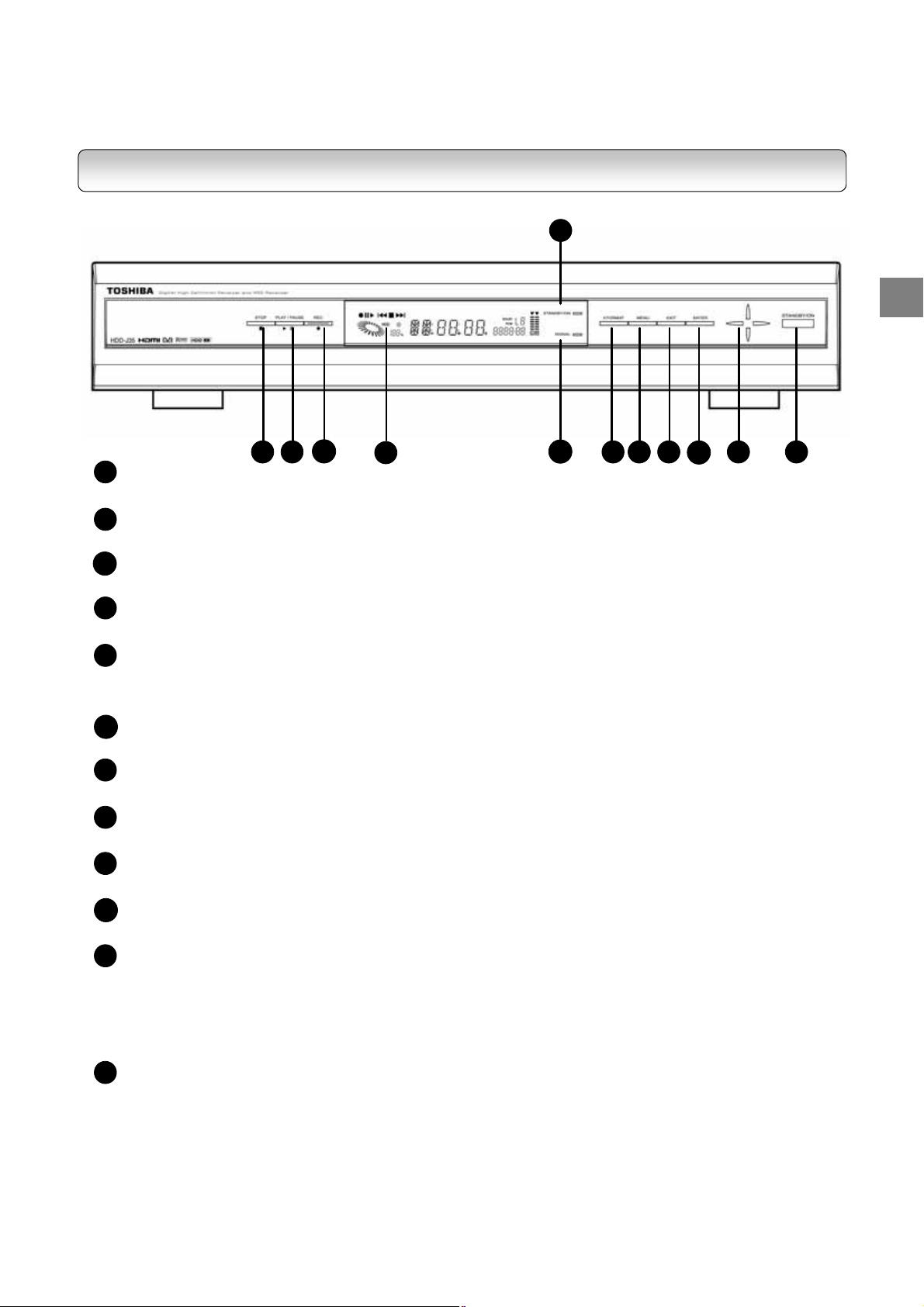
FRONT PANEL
5
INTRODUCTION
1 2
1
STOP button
Stops playback or recording
PLAY/PAUSE button
2
Starts or pause playback
3
REC button
Starts recording
4
Front Panel Display
Refer to page 10
5
STANDBY/ON indicator
Displays the operational state of the recorder
Green LED: Recorder in power on mode; Red LED: Recorder in standby mode
SIGNAL indicator
6
ON: Signal captured; OFF: No signal
7
V. FORMAT button
Toggles among AUTO, 1080i, 720p, 576p and 576i video output formats.
8
TOP MENU button
Activates the On Screen Menu
9
EXIT button
Exits from the main menu or returns to the Main menu from submenu
10
ENTER button
Selects the highlighted menu or submenu item
11
Directional buttons
- Move the selection focus on the screen
- Left and right buttons for increasing and decreasing audio volume
- Up and down buttons on front panel changes main program channels
- Up and down buttons on remote control unit changes PIP channels
STANDBY/ON button
12
Toggles the recorder between power-on and standby modes
3
4
6
7 8 9
10
11 12
11
Page 12

REAR PANEL
1
2
3
4
5
6
7
8
9
10
11
12
15
DIGITAL
AUDIO OUT
(COAXIAL)
HDMI
(OPTICAL)
14
16
e
x
r
t
n
e
V
.
.
D
g
.
V
D
D
g
D
V
.
D
.
i
n
t
p
u
i
a
v
l
t
e
h
ANALOG
AUDIO OUT
L
L
R
R
17
n
c
t
o
r
o
p
a
M
l
y
l
e
a
r
)
r
)
e
,
y
y
e
a
r
)
l
h
i
t
c
-
S
E
w
D
O
a
l
D
l
p
p
e
SD VIDEO OUT
VIDEO
S-VIDEO
t
e
x
e
n
e
n
e
a
u
i
t
e
s
n
o
t
i
B
G
10
12
HD VIDEO OUT
Y/G
P
/B
H
B
V
P
R
11
RGB
/R
13
e
v
i
c
e
s
f
o
r
l
n
d
a
u
o
e
o
t
v
i
d
u
d
i
o
t
o
p
u
u
t
e
o
i
o
d
v
t
o
i
n
R
T
V
’
s
e
,
s
u
t
p
s
r
t
p
u
t
s
(
e
u
(
t
e
s
.
g
(
e
t
p
s
u
H
B
V
G
b
l
t
e
a
c
2
AC IN
~
1
C
A
A
M
0
N
o
F
o
E
o
D
o
P
o
U
o
s
O
o
-
o
O
o
,
P
o
0
T
r
r
R
r
BPR
r
D
r
e
M
r
V
r
M
r
V
e
s
BPR
r
O
I
M
s
4
~
2
.
I
N
n
c
o
T
U
o
n
c
L
I
A
o
n
c
O
w
i
t
c
o
n
I
O
n
c
o
t
o
d
P
O
o
n
c
E
D
c
o
n
P
O
o
n
c
U
O
d
t
n
c
o
1
A
F
R
F
S
F
H
T
Y
F
A
F
u
C
F
S
F
C
F
H
U
Y
F
ANT. 1 IN
ANT. 2 IN
RF 2 OUT
RF 1 OUT
3
P
S
P
L
U
S
I
N
/
6
,
5
0
n
e
0
V
C
A
c
t
i
o
t
o
n
SERIAL PORT
4
Y
0
z
H
F
H
/
V
F
H
U
HD MODE
RGB
5
n
t
a
n
e
a
n
V
T
P
a
m
t
e
t
e
/
L
t
e
’
l
o
f
o
o
r
r
BPR
/
r
s
O
R
e
u
g
o
f
s
t
w
r
e
d
b
e
l
/
V
n
A
a
l
A
/
V
n
a
I
N
L
I
(
R
N
l
A
/
V
a
n
S
-
V
e
i
d
T
U
o
r
T
V
’
e
c
n
t
i
o
n
n
a
t
o
T
R
O
P
n
e
c
n
t
i
o
t
o
P
C
i
t
w
c
-
E
D
c
H
h
(
I
N
L
c
n
e
/
R
L
n
e
c
e
t
g
S
I
T
e
c
n
O
O
n
e
c
S
I
T
c
n
e
h
S
u
t
o
t
p
u
D
)
1
t
o
n
e
t
i
o
I
N
t
i
o
r
h
e
E
t
i
o
T
U
t
i
o
E
t
i
o
x
o
x
e
t
n
i
t
h
w
Y
V
E
I
D
O
o
e
x
n
t
V
n
t
o
T
E
O
I
D
V
o
V
C
n
t
t
’
s
a
n
u
p
a
r
e
e
t
e
w
n
e
q
u
i
p
q
u
e
i
p
2
)
e
i
q
p
u
o
i
n
p
u
s
V
i
d
e
T
O
T
U
a
(
b
L
i
t
h
B
G
e
o
t
g
r
h
e
O
B
G
/
R
e
c
n
n
t
i
o
R
w
T
U
T
t
o
P
V
Y
’
s
BPR
e
p
m
o
(
c
L1 IN
Y
P
B
P
R
576i ONL Y
YP
BPR
6
i
n
n
e
a
n
r
e
a
g
d
B
G
a
R
w
n
t
e
m
n
t
e
m
w
e
m
n
t
w
L2 IN
VIDEO
L
L
R
R
7
8 9
p
u
t
o
r
t
o
o
t
h
e
r
P
Y
n
d
BPR
i
t
h
h
i
t
i
t
h
o
c
o
p
m
n
a
a
l
o
g
c
o
p
m
o
t
t
o
s
i
n
p
u
12
l
)
n
e
o
n
o
n
c
n
e
,
r
f
o
i
d
e
t
v
c
o
)
o
r
R
12
Page 13

REAR PANEL
B
G
R
13
o
r
F
c
I
M
D
H
14
r
c
o
F
I
T
I
G
D
15
o
r
F
c
I
G
I
T
D
16
o
o
r
F
L
A
A
17
N
r
c
o
F
(Mi
o
n
O
o
n
A
o
a
A
p
t
O
o
n
T
5
-
p
)
i
T
T
c
O
n
1
V
’
s
i
M
V
’
s
D
H
I
A
A
O
X
t
i
t
o
o
n
A
I
C
T
P
t
o
a
n
t
i
o
U
O
/
R
o
r
R
V
C
i
-
S
D
n
e
c
n
t
T
U
c
t
n
e
A
L
U
x
i
a
l
c
A
L
U
l
i
c
c
a
G
U
A
c
n
t
e
u
b
o
n
i
o
t
i
o
n
t
o
I
(
O
C
D
n
n
o
e
I
(
O
D
n
n
e
c
o
L
I
O
D
i
o
n
t
o
U
O
5
-
p
i
n
i
u
n
t
n
-
i
S
D
I
M
L
)
n
a
L
)
n
a
T
V
T
1
u
b
i
u
n
t
p
T
U
O
i
l
f
i
p
a
O
’
m
s
m
e
r
T
U
p
l
i
f
i
e
r
e
d
A
i
u
o
L
p
e
l
c
d
®
i
t
i
g
D
D
i
g
i
t
a
y
l
i
t
h
w
d
p
e
p
i
q
u
e
e
p
d
p
u
i
q
d
A
i
u
/
R
h
i
t
w
o
i
n
p
u
b
a
o
D
a
o
l
D
b
y
®
t
s
a
o
r
d
e
l
d
e
c
e
o
r
d
INTRODUCTION
13
Page 14
REMOTE CONTROL
1
2
3
4
6
7
8
9
10
11
12
22
23
24
25
5
26
27
28
29
30
INTRODUCTION
31
32
13
14
15
16
17
18
19
20
21
33
34
35
36
37
38
39
40
41
42
43
14
Page 15

1
2
3
4
5
6
7
8
9
10
11
12
13
14
15
16
17
18
19
20
21
22
23
24
25
26
27
28
29
30
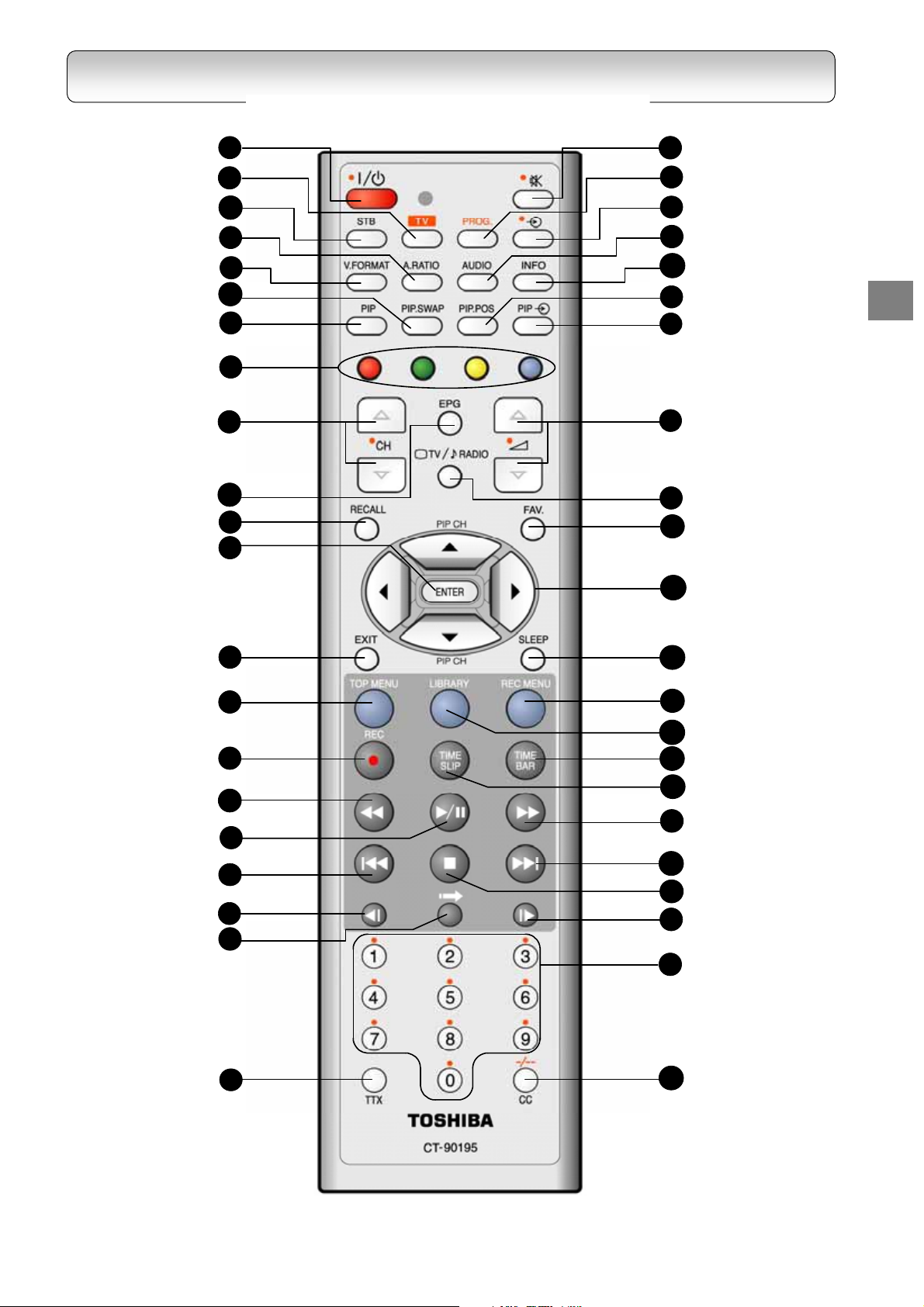
REMOTE CONTROL
STANDBY/ON button
TV FUNCTION button*
SET TOP BOX button**
ASPECT RATIO button
VIDEO FORMAT button
PIP. SWAP button
PIP button
COLOUR buttons***
CHANNEL UP/DOWN buttons
EPG button
RECALL button
ENTER button
EXIT button
TOP MENU button
RECORD button
FAST REVERSE button
PLAY/PAUSE button
SKIP REVERSE button
SLOW REVERSE button
INSTANT SKIP button
TTX button
MUTE button
PROG. button
INPUT SELECT button
AUDIO button
INFO button
PIP. POS button
PIP. AUX button
VOLUME UP/DOWN buttons
TV/RADIO button
Page 49
Page 50
Page 49
Page 38, 48 and 58
Page 53
Page 11
Page 11
Page 33
Page 56
Page 29
Page 77
Page 53
Page 47
Page 49
Page 49
Page 48
Page 27
Page 39
Page 39
Page 43, 57 and 62
Page 29
Page 65
Page 63 and 65
Page 65
Page 65
Page 65
Page 52
Page 29
31
32
33
34
35
36
37
38
39
40
41
42
43
FAV. button
DIRECTIONAL buttons
SLEEP button
REC MENU button
LIBRARY button
TIME BAR button
TIME SLIP button
FAST FORWARD button
SKIP FORWARD button
STOP button
SLOW FORWARD button
CHANNEL NUMBER buttons
CC/DIGIT SELECTION button
* TV FUNCTION – Set the Remote Control Unit
to function with the Television Set. See RCU
programming guide on page 77.
** SET TOP BOX– Set the Remote Control Unit
to function with the Set Top Box.
*** COLOUR buttons from left to right: Red,
Green, Yellow, Blue
Page 42
Page 11
Page 52
Page 57
Page 62
Page 63
Page 63
Page 65
Page 65
Page 11
Page 65
Page 29
Page 50/77
15
Page 16
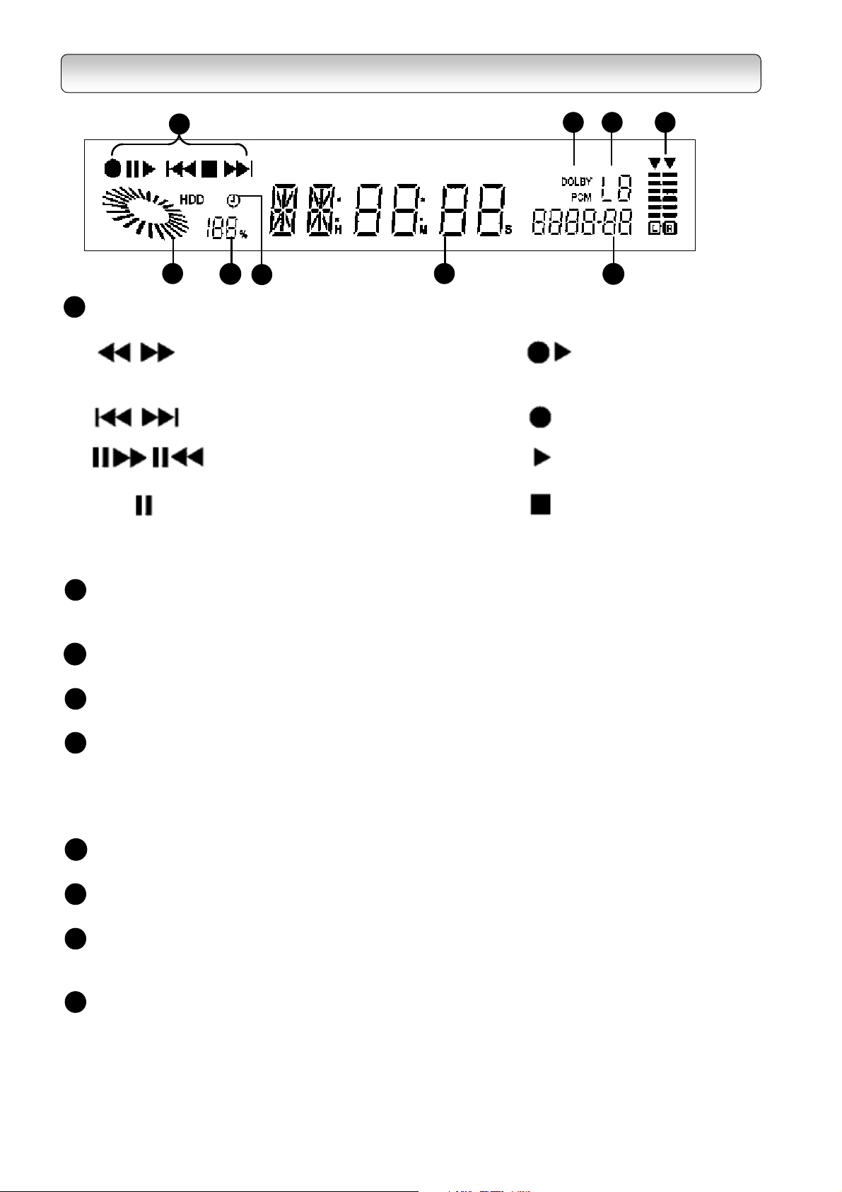
FP DISPLAY
1
2
1
Operation Indicator
7 8 9
3
4
Fast Reverse or Fast Forward Ext. Rec.
Skip Reverse or Skip Forward Recording
Frame Forward or Frame Reverse Playback
Playback PAUSE Stop
5
(Flashing)
6
HDD Operation Indicator
2
Animates when recorder is in HDD playback or recording mode else it
indicates used HDD storage space
3
HDD Storage Indicator
Indicates percentage of remaining HDD storage space
Timer Recording Indicator
4
Illuminates when the recorder has scheduled program for recording
Time and Channel Display
5
a) Shows time as default (HH:MM) in 12 or 24 hours
b) Shows channel number for 5 seconds after every channel change
c) Shows HH:MM:SS during playback and recording mode
d) Shows progress of Automatic Software Upgrade
Video Format Indicator
6
Indicates current HD or SD display format including 1080i, 720p, 576p and 576i
Audio Format Indicator (PCM/Dolby)
7
Indicates current audio format
Auxiliary Input Indicator (L1/L2)
8
Indicates source of input through which external devices are connected. (e.g. DVD player)
L1 = Component Video Input, L2 = Composite Video Input
9
Volume Indicator
Displays the audio output level
Level indicator may not show exact sound level, it only shows the average level
16
Page 17

Chapter Two
STARTUP GUIDANCE
Read this chapter first to make all necessary preparations.
1
Installing the Recorder 18
- Connections 18
- Preparing your remote control 25
- Setting up your recorder 27
2
Viewing programs 29
3
Turning off the recorder 29
4
Status display 30
17
Page 18
INSTALLING THE RECORDER
Follow steps A to C below. Your recorder will be ready to display digital programs on your TV.
STEP A: CONNECTIONS
DO NOT PLUG THE RECORDER INTO THE MAINS YET.
Before you use this recorder, it is necessary to connect it to your TV.
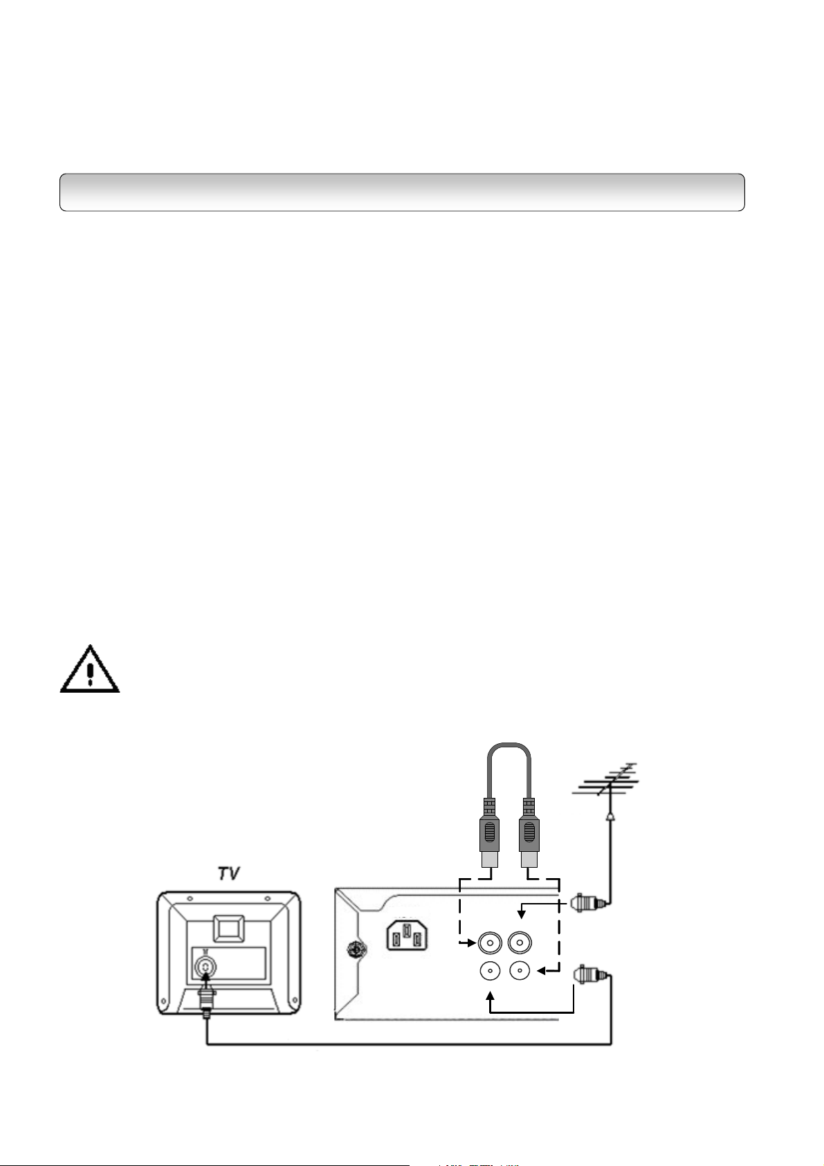
1
CONNECTING TO TV
1-1.
Disconnect the antenna cable from your TV and connect it to the “ANT. 1 IN” terminal on the back of the
recorder.
1-2.
To achieve RF loop-through for the in-built twin RF tuners, connect the RF Coaxial Connectors (supplied) to the
“RF 1 OUT” and “ANT. 2 IN” terminals as shown in the diagram below.
1-3.
The “RF 2 OUT” provides you a RF loop-through function to receive analogue TV programs as well as digital
programs (for Integrated Digital TVs only). Use an RF coaxial cable (not supplied) to connect the HDD-J35 “RF 2
OUT” terminal to TV’s or VCR’s antenna input.
Connection to Antenna
RF Loop-through Connection
“RF OUT” Connection to TV or VCR
Before connecting or disconnecting the antenna cable, unplug the recorder, VCR, TV and
antenna booster, if any.
18
RF Coaxial
Connector
Antenna cable
(not supplied)
HDD-J35
AC IN
~
RF coaxial cable
To TV antenna input
(not supplied)
ANT. 1 IN
RF 1 OUT
ANT. 2 IN
RF 2 OUT
Page 19
1-4.
Connections to TV – Video Connection
In the accessory box, you will find two sets of cables: One is the component video cable (with red, green and
blue connectors) and the other is the Audio/Video cable (with yellow, white and red connectors).
For better video quality, it is recommended that you use the HDMI cable, the Mini D-Sub 15-pin cable or the
RGBHV video cable (with 5 RCA connectors). These cables are not included in the HDD-J35 package.
HD MODE Switch selection is essential for several outputs. Refer to the HD MODE Switch table on page 71 for
making the correct switch selection according to your output connection.
You have 6 choices for connecting the video output from the recorder to your TV. Use only one of the following
connections (with (a), (b) or (c) being the best choice):
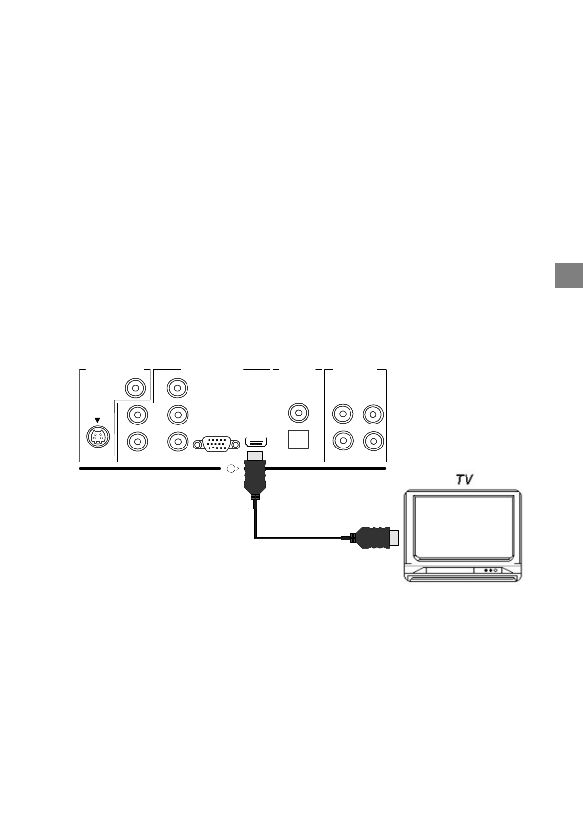
(a) HDMI connection: If your TV has HDMI input, use a HDMI cable (not supplied) to connect the
recorder to your TV. HDMI supports video and multi-channel audio in a single cable, therefore
separate connection for audio is not necessary.
SD VIDEO OUT
VIDEO
S-VIDEO
HDD-J35
HD VIDEO OUT
Y/G
P
/B
H
V
B
RGB
/R
P
R
HDMI
DIGITAL
AUDIO OUT
(COAXIAL)
(OPTICAL)
L
R
ANALOG
AUDIO OUT
L
R
To TV HDMI input
HDMI cable
(not supplied)
STARTUP GUIDANCE
Note: Because HDMI is an evolving technology, it is possible that some TVs may not operate properly
with the recorder.
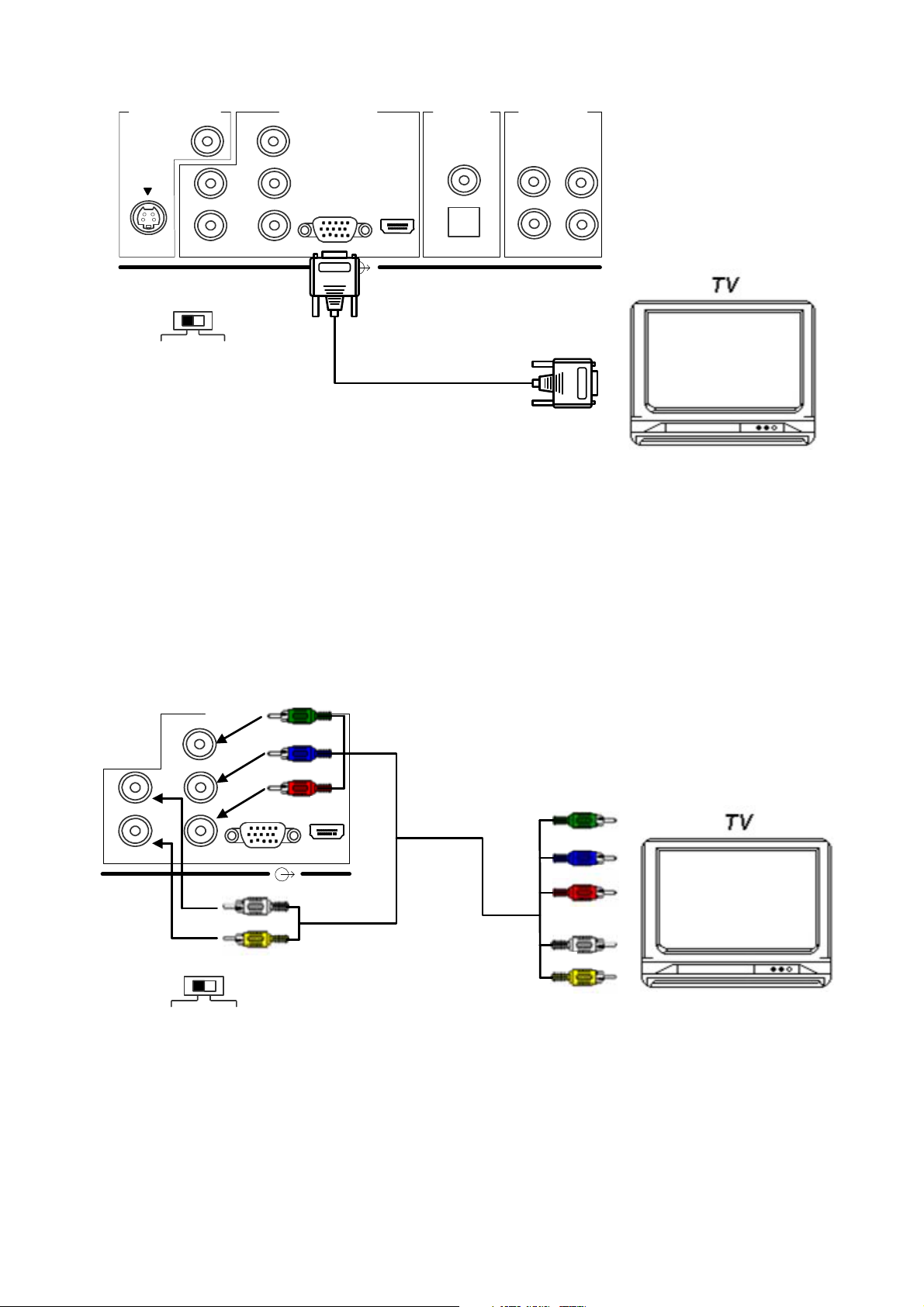
(b) Mini D-Sub 15-pin connection: If your TV has a RGB Mini D-Sub 15-pin video input connector, use a
Mini D-Sub 15-pin cable (not supplied) to connect the recorder to your TV. Set the HD MODE Switch
(refer to page 12) to RGB, and then connect the RGB connector on the rear of the recorder to the
corresponding socket on the TV.
Do not connect any PC monitor to the recorder via Mini D-Sub 15-pin cable.
19
Page 20
SD VIDEO OUT
VIDEO
S-VIDEO
H
V
HD MODE
HDD-J35
HD VIDEO OUT
Y/G
/B
P
B
RGB
/R
P
R
HDMI
DIGITAL
AUDIO OUT
(COAXIAL)
(OPTICAL)
L
R
ANALOG
AUDIO OUT
L
R
To TV Mini D-Sub 15-pin
RGB
YPBP
R
video input
Mini D-Sub 15-pin video cable
(not supplied)
Note: This diagram illustrates video connections only. Refer to Page 22 for Audio connection.
RGBHV (RCA) connection
(c)
: If your TV has RGBHV video inputs, use a RGBHV video cable (not
supplied) to connect the recorder to your TV. Set the HD MODE Switch (refer to page 12) to RGB, and
then connect the Y/G, P
/B, PR/R, H and V connectors from “HD VIDEO OUT” on the rear of the
B
recorder to the corresponding jacks on the TV.
Match the
HDD-J35
H
V
P
P
Y/G
B
R
HD VIDEO OUT
G
B
/B
RGB
/R
R
HDMI
H
colors when
connecting
To TV RGBHV
video inputs
G
B
R
RGBHV video cable
RGB
HD MODE
YPBP
V
R
(not supplied)
H
V
Note: This diagram illustrates video connections only. Refer to Page 22 for Audio connection.
20
Page 21
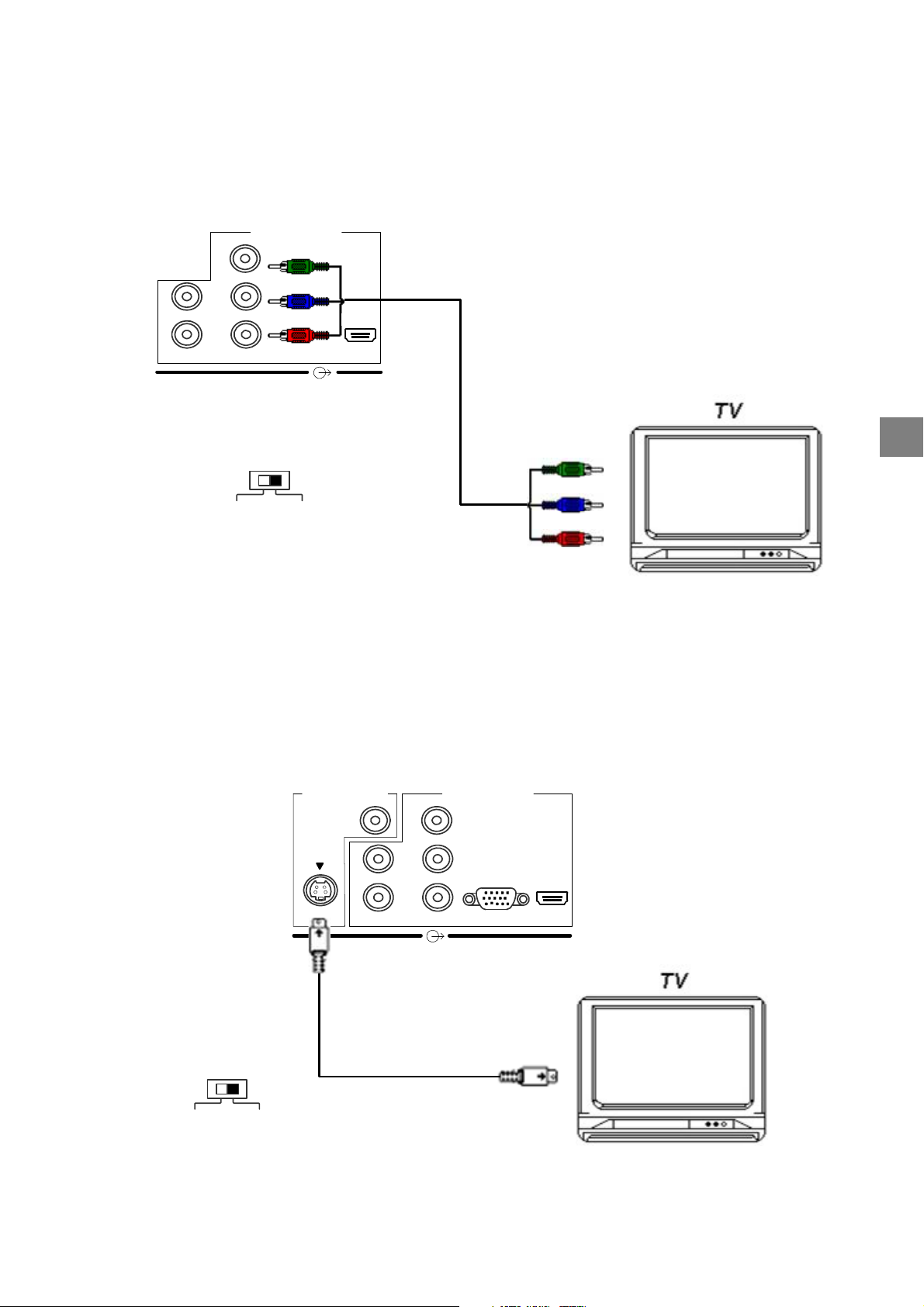
(d) YPBPR connection
: If your TV has component video inputs, use the component video cable included
in the HDD-J35 accessory box. Set the HD MODE Switch (refer to page 12) to YP
connect the Y/G, P
/B and PR/R connectors from “HD VIDEO OUT” on the rear of the recorder to the
B
corresponding jacks on the TV.
HDD-J35
HD VIDEO OUT
Y/G
P
/B
H
V
B
RGB
P
/R
R
Y
P
HDMI
P
B
R
Component video cable
(supplied)
HD MODE
YP
RGB
BPR
Match the
colors when
connecting
To TV Y/PB/P
video inputs
Y
B
P
P
R
R
, and then
BPR
STARTUP GUIDANCE
Note: This diagram illustrates video connections only. Refer to Page 22 for Audio connection.
(e)
S-Video connection
the recorder to your TV. Set the HD MODE Switch (refer to page 12) to YP
: If your TV has an S-Video input, use an S-Video cable (not supplied) to connect
, and then connect the S-
BPR
Video connector from “SD VIDEO OUT” on the rear of the recorder to the corresponding jack on the TV.
HDD-J35
S-Video cable
(not supplied)
HD MODE
SD VIDEO OUT
VIDEO
S-VIDEO
Y/G
P
H
V
B
P
R
To TV S-Video input
/B
/R
HD VIDEO OUT
RGB
HDMI
YP
RGB
BPR
Note: This diagram illustrates video connections only. Refer to Page 22 for Audio connection.
21
Page 22
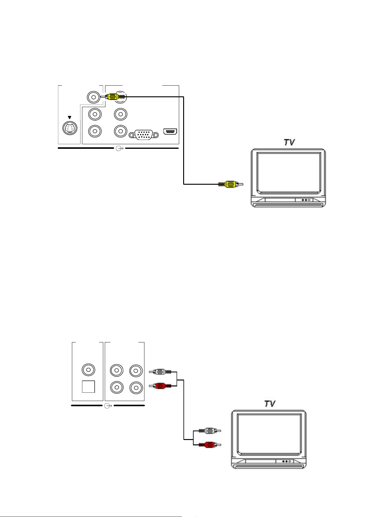
(f)
Composite video connection
: If your TV has composite video inputs, use the yellow connector of the
Audio/Video cable included in the HDD-J35 accessory box. Connect the yellow video connector from
“SD VIDEO OUT” on the rear of the recorder to the corresponding jack on the TV.
HDD-J35
SD VIDEO OUT
VIDEO
S-VIDEO
Y/G
/B
P
H
V
B
P
/R
R
HD VIDEO OUT
RGB
Match the
colors when
connecting
HDMI
Audio/Video cable
(supplied)
Note: This diagram illustrates video connections only. Refer to Audio connection below.
To TV composite
video input
1-5.
Connections to TV – Audio Connection
For audio connections, you have two choices. You can connect the recorder to your TV or to an audio amplifier
equipped with a Dolby® Digital decoder. If you
do not
have an external amplifier equipped with a Dolby® Digital
decoder, use the red and white connectors of the Audio/Video cable included in the package. Connect the audio
connectors from “ANALOG AUDIO OUT” on the rear of the recorder to the corresponding jacks on the TV: red to
red (right audio) and white to white (left audio).
Note: If your TV has only one audio input jack, connect either the right or left audio connector to the audio jack.
Do not connect the yellow connector to TV if using HDMI, RGB, component video or S-Video connector.
HDD-J35
DIGITAL
AUDIO OUT
ANALOG
AUDIO OUT
22
(COAXIAL)
(OPTICAL)
L
R
L
R
Audio/Video cable
(supplied)
white
red
Match the
colors when
connecting
white
red
To TV audio inputs
Page 23
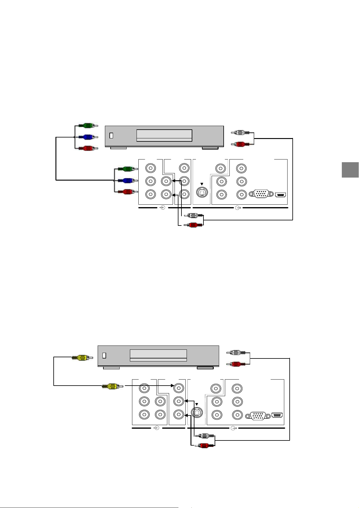
2
CONNECTING TO DVD PLAYER
For TV sets with limited component video inputs, this recorder can be used to connect a DVD player through the
Component Video and Stereo Audio input connectors located at the back of the HDD-J35 recorder.
Use a component video cable to connect from the DVD player’s YP
output to the HDD-J35 YPBPR input
BPR
connectors; Use an Audio/Video cable to connect the audio connectors from DVD player’s audio output to the
HDD-J35 Audio L/R input connectors: red to red (right audio) and white to white (left audio).
B/PR
To DVD Y/P
video outputs
Y
P
B
P
R
DVD Player
L1 IN
Y
VIDEO
L2 IN
SD VIDEO OUT
VIDEO
To DVD audio outputs
white
red
HD VIDEO OUT
Y/G
Y
Component video cable
(supplied)
Match the
colors when
connecting
B
P
R
L
R
576i ONLY
P
B
P
R
L
R
S-VIDEO
white
red
P
/B
B
H
V
/R
P
R
HDD-J35
RGB
HDMI
Audio/Video cable
(supplied)
P
Important: 1. This setup is only for output connection made via HDMI.
2. The YP
input connectors on this recorder accepts only 576i signal, therefore the DVD
BPR
player connected must be set to output in interlaced format. Refer to your DVD player’s
manual for settings.
STARTUP GUIDANCE
3
CONNECTING TO CABLE BOX/SATELLITE BOX/VCR
A cable box, satellite box or VCR can be connected to this recorder through the Composite Video and Stereo
Audio input connectors located at the back of the HDD-J35 recorder. Use a composite Audio/Video cable to
connect from the Cable Box/Satellite Box/VCR’s Video/L/R output to the HDD-J35 Video/L/R input connectors.
CABLE BOX/
To Composite Video
SATELLITE BOX/VCR
outputs
SD VIDEO OUT
VIDEO
S-VIDEO
Audio/Video cable
(supplied)
Match the
colors when
Y
P
P
B
R
L1 IN
576i ONLY
L2 IN
VIDEO
L
R
L
R
connecting
Important: This setup is only for output connection made via HDMI.
To Audio outputs
Y/G
P
H
V
B
P
R
white
red
white
red
HD VIDEO OUT
/B
RGB
/R
HDD-J35
Audio/Video cable
(supplied)
HDMI
23
Page 24
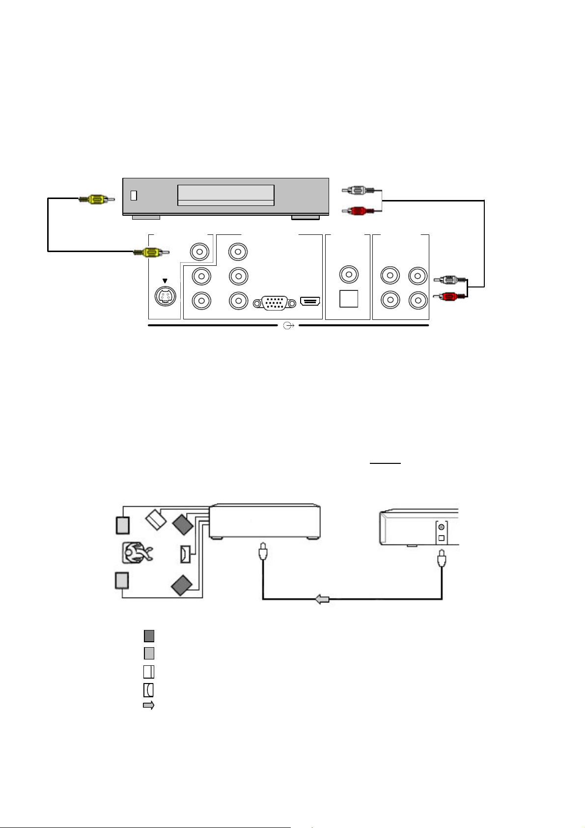
4
CONNECTING TO VCR (FOR ARCHIVING)
A VCR can also be connected to this recorder through the Composite Video and Stereo Audio output connectors
located at the back of the HDD-J35 recorder for archiving programs from the HDD. Use a composite Audio/Video
cable to connect from the HDD-J35 Video/L/R output connectors to the VCR’s Video/L/R input.
To Composite Video
inputs
VCR
To Audio inputs
white
Audio/Video cable
(supplied)
red
Audio/Video cable
(supplied)
Match the
SD VIDEO OUT
VIDEO
H
V
HD VIDEO OUT
Y/G
P
/B
B
RGB
/R
P
R
HDMI
DIGITAL
AUDIO OUT
(COAXIAL)
(OPTICAL)
L
R
ANALOG
AUDIO OUT
L
R
white
red
colors when
connecting
HDD-J35
5
CONNECTING TO AMPLIFIER
If you connect this recorder to an audio amplifier equipped with a Dolby® Digital decoder, use an optical or
coaxial digital cable (not supplied) to connect from the recorder’s “DIGITAL AUDIO OUT (Optical/Coaxial)” to
the digital audio input of your amplifier.
In this case make sure that you do not need to connect the audio
connectors (red and white) on the Audio/Video cable to your TV.
Amplifier equipped with
a Dolby decoder
(OPTICAL or COAXIAL)
Optical or Coaxial digital cable (not supplied)
: Front speaker
: Rear speaker
Subwoofer
: Centre speaker
: Signal flow
HDD-J35
TO DIGITAL AUDIO
24
Page 25
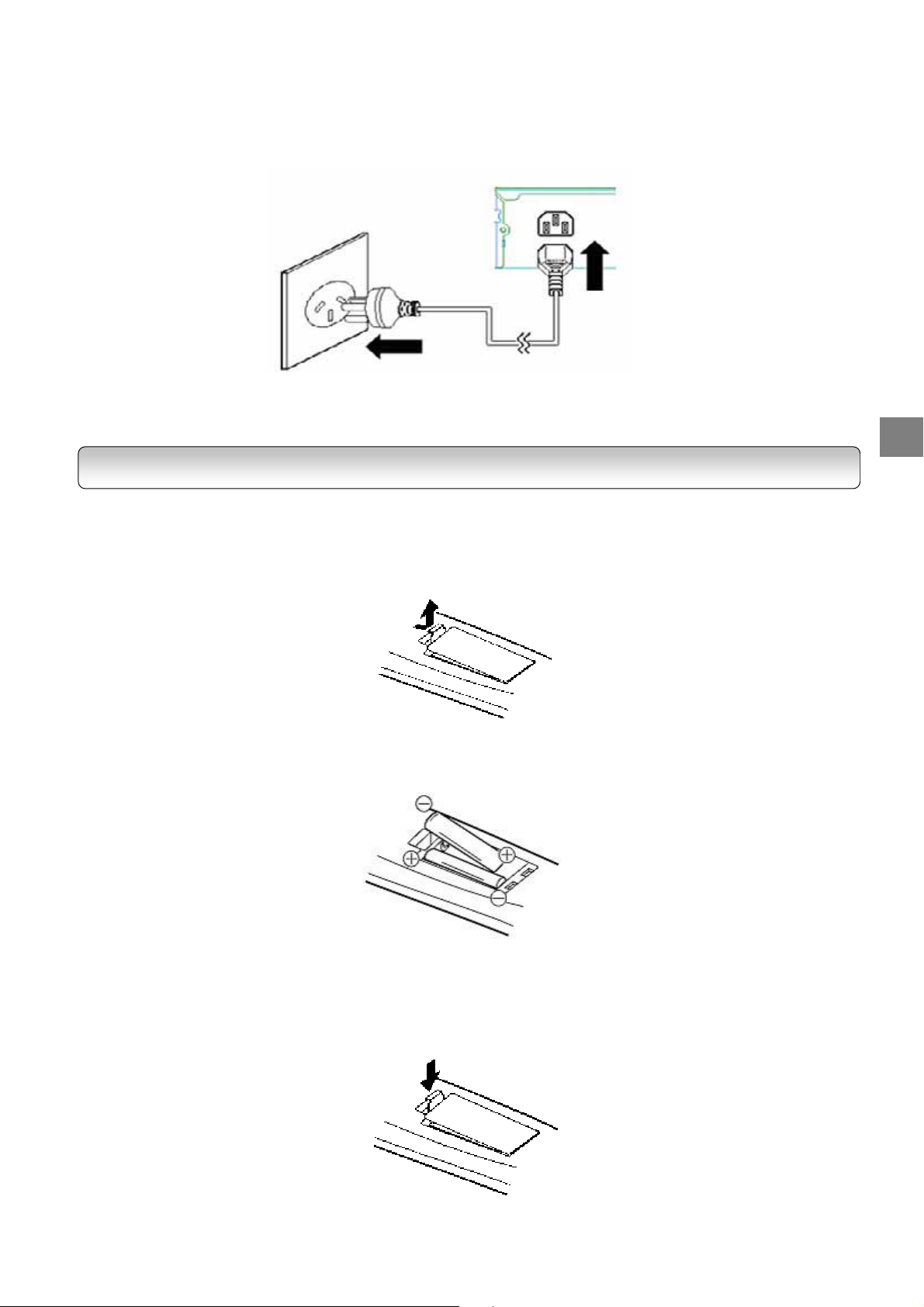
6
CONNECTING TO MAINS SUPPLY
Plug the recorder into the mains.
The above diagram is illustrated with an Australian power plug.
In other regions, use the appropriate power plug.
Wall Outlet
STEP B: PREPARING YOUR REMOTE CONTROL
Loading batteries
1
. Open the Cover.
HDD-J35
AC IN
~
Power Cord
(supplied)
STARTUP GUIDANCE
2
. Insert two R6 (AA size) batteries.
-
Make sure to match the + and – signs on the batteries to the marks inside the battery compartment.
3
. Close the cover.
25
Page 26
Notes on batteries
Improper use of batteries may cause battery leakage and corrosion. To operate the remote control correctly,
follow the instructions below.
Do not insert batteries into the remote control in the wrong direction.
Do not charge, heat, open, or short-circuit the batteries. Do not throw batteries into fire.
Batteries contain toxic substances. Do not dispose of them with ordinary trash. Dispose of batteries only
in accordance with local ordinances.
Do not leave dead or exhausted batteries in the remote control.
Do not use different types of batteries together, or mix old and new batteries.
If you do not use the remote control for a long period of time, remove the batteries to avoid possible
damage from battery corrosion.
If the remote control does not function correctly or if the operating range becomes reduced, replace all
batteries with new ones.
If battery leakage occurs, wipe the battery liquid from the battery compartment, then insert new batteries.
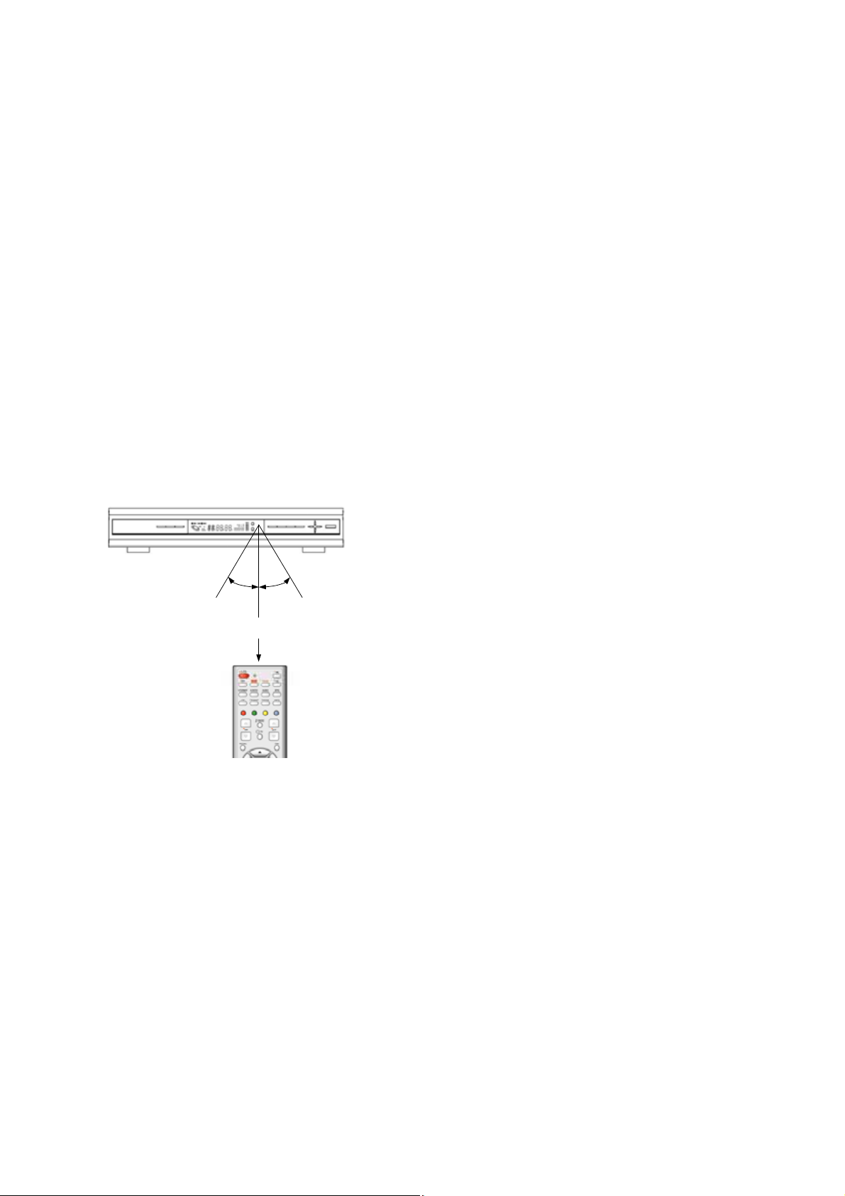
Operating with the remote control
1.
Point the remote control at the remote sensor and press
the buttons.
2.
Distance: About 5 m from the front of the remote sensor.
O
30
Within about 5m
Do not expose the remote sensor of the recorder to a strong light source such as direct sunlight or other
illumination. If you do so, you may not be able to operate the recorder via the remote control.
Do not drop or give the remote control a shock.
Do not leave the remote control near an extremely hot or humid place.
Do not spill water or put anything wet on the remote control.
30
O
3.
Angle: About 30° in each direction of the front of the remote
sensor.
Do not disassemble the remote control.
26
Page 27

STEP C: SETTING UP YOUR RECORDER
p
y
Note: If your service provider or antenna installer has already installed your TV system to receive terrestrial TV
programs, do not change any connections of those devices or installation settings unless it is absolutely
necessary.
If your service provider or system installer has not configured your recorder, it will not be set up for any
specific channel or frequency when powered on for the first time. In this case you should follow the steps
below to set up your recorder.
1.
Switch on the TV.
2.
Using your TV’s remote control, select the appropriate external Audio/Video input on your TV according to
the connection you have made in Step A.
3.
Make sure the recorder is already in power-on mode (LED in green colour). If it is in standby mode (LED in
red colour), switch on the recorder by pressing the “STANDBY/ON” button on the front panel of the recorder or
on the remote control.
4.
A message “Database is Empty” should appear after a while. If you can see the message, go to Step 5
directly; However, if you cannot see the message on the screen even after a long time, change the video format
by pressing V.FORMAT button on remote control or on the front panel. Press V.FORMAT button until you see
the message “Database is Empty”.
Note: When you press V.FORMAT button, the Video Format Indicator on the recorder’s front panel will display
among “576i” (for HD MODE Switch being set to YP
press V.FORMAT button, make sure the front panel display has changed before you press the button again.
5.
After you see a message “Database is Empty” appears, press the “TOP MENU” button. A “Region Selection”
menu appears.
only), “AUTO”, “1080i”, “720p” and “576p”. After you
BPR
STARTUP GUIDANCE
−
Use the directional buttons “Ż” and “Ź” to
highlight your region of residence and
“ENTER” button to make your selection. The
region setup process ma
to complete.
−
If the “Region Selection” menu does not
appear, refer to “RESET DATA” on page 35 to
reset the database.
take a few minutes
ress the
27
Page 28

6.
You will see the Main Menu (page 33). Press the “ź” button twice to highlight “INSTALLATION” and then
press “ENTER”. When prompted, enter “0000” which is the default password.
7.
To tune the recorder, you have choices of MANUAL SETUP / AUTO SCAN / QUICK SCAN. We recommend
that you use “QUICK SCAN” (page 34) for a faster setup. For more information on the various tuning options,
refer to pages 34~35.
Note: The choices of AUTO SCAN and QUICK SCAN are for Australia only.
8.
If you use “QUICK SCAN” in step 7 and when you see the message “>>> SCAN COMPLETE <<<”, press
the “EXIT” button several times until the main menu disappears.
9.
After you finish scanning, you can choose the suitable V.FORMAT. If you use an SDTV, use the V.FORMAT
“576i”; If you use a HD-ready TV, you are recommended to change to “AUTO” by pressing V.FORMAT button;
However, if your HD-ready TV cannot display some specific video format, press V.FORMAT button to change to
an appropriate fixed format.
10.
Congratulations! You have successfully setup your recorder.
28
Page 29

VIEWING PROGRAMS
1
. After you have tuned the recorder, you have several ways to navigate through all programs:
− Press the “CHANNEL NUMBER” or “CHANNEL UP/DOWN” buttons to select a program of your interest.
− Press the “TV/RADIO” button to call up the “Program List” (page 48) and select a program of your
interest. This will also set your viewing mode to “Normal”.
− Press the “FAV.” button to call up the “Favorite Channel List” and select a program of your interest (page
48). Entries in this “Favorite Channel List” are those that you have added under “FAVORITE&LOCK”
(page 42). This will set your viewing mode to “Favorite”.
− Use the “CHANNEL UP/DOWN” buttons to view the previous and next program. The programs are
arranged according to the “Program list” or “Favorite Channel List” (depending on your current viewing
mode). See “I-PLATE (INFO)” on page 47 for more information on viewing modes.
2
. Press the “INFO” button to view details on a program.
3
. Press the “EPG” button to view the Electronic Program Guide on a weekly basis.
4
. Press the “VOLUME UP/DOWN” buttons to increase or decrease the audio volume, or press the “MUTE”
button to turn off the audio output.
5
.The information contained in this chapter (“STARTUP GUIDANCE”) is only meant to be a quick installation
guide. Familiarize yourself with other functions of the recorder by reading the remaining chapters in this manual.
TURNING OFF THE RECORDER
Set the recorder to standby mode by pressing the “STANDBY/ON” button.
If you would not use the recorder for a long time, unplug the power cord from the wall outlet to completely
eliminate all voltages.
STARTUP GUIDANCE
29
Page 30

STATUS DISPLAY
Each time you operate the recorder, the following display appears on the TV screen to indicate the status of the
recorder.
Eg. Status Display
List of Status Display
Playback
Playback Pause
Stop
3
3
3
Fast Forward (3 speeds)
Fast Reverse (3 speeds)
Skip Forward
Skip Reverse
Slow Forward (3 speeds)
30
3
Slow Reverse (3 speeds)
Frame Forward
Frame Reverse
Record
Ext. Rec
Page 31

Chapter Three
RECEIVING
1
Top Menu
Menu Map 32
Main Menu 33
Installation 33
− Quick Scan 34
− Auto Scan 34
− Manual Setup 35
− Reset Data 35
− Format Hard Disk 36
− S/W Update 36
Program 38
− Program List 38
− EPG 38
System 39
− Video Setup 39
− Audio Setup 40
− Password 40
− Time Setup 41
− Ext Control 41
Edit channel 42
− Favorite&Lock 42
− Parental Rate 43
− Virtual Keyboard 43
Profile 44
− I-Plate Setup 44
− FP Display Setup 45
− Information 45
− PVR Setup 46
2
Quick Control
− Info 47
− TV/Radio 48
− EPG 48
− Fav 49
− PIP 49
− TTX 50
− CC 50
− Freeze 50
− V.Format 51
− A.Ratio 51
− Input Select 52
− Sleep 52
− Audio 53
− Recall 53
31
Page 32

TOP MENU
MENU MAP
Use the directional buttons to navigate through the menu, “ENTER” button to choose specific items, and “EXIT”
button to return to the main menu from sub-menu or to leave the main menu.
MAIN MENU
page 33
PROGRAM
page 38
EDIT CHANNEL
page 42
FAVORITE&LOCK
page 42
PARENTAL RATE
page 43
PROGRAM LIST
page 38
EPG
page 38
INSTALLATION
page 33
SYSTEM
page 39
PROFILE
page 44
I-PLATE SETUP
page 44
FP DISPLAY SETUP
page 45
INFORMATION
page 45
PVR SETUP
Page 46
VIDEO SETUP
page 39
AUDIO SETUP
page 40
PASSWORD
page 40
TIME SETUP
page 41
EXT CONTROL
page 41
QUICK SCAN
page 34
AUTO SCAN
page 34
MANUAL SETUP
page 35
RESET DATA
page 35
FORMAT HARD
DISK
page 36
S/W UPDATE
page 36
32
Note: If you leave the menu screen for a long period of time, a permanent afterimage may remain on the
TV screen.
Page 33

MAIN MENU
There are two ways to enter the Main Menu when the recorder is powered on:
1.
On the remote control, press the “TOP MENU”
button.
2.
Alternatively, press “MENU” button on the
front panel.
3.
Use the directional buttons to navigate
through the menu, “ENTER” button to choose
specific items, and “EXIT” button to return to
the main menu from submenu or to leave the
main menu.
4.
Menu(s) left displayed for 15 minutes will exit
automatically.
INSTALLATION
On the main menu, select “INSTALLATION” and key-in your password to enter the “INSTALLATION” page. The
default password is 0000. Refer to page 40 to change the password.
If you are in Australia, you have choices of MANUAL SETUP / AUTO SCAN / QUICK SCAN to tune the recorder.
If you stay in other region, use MANUAL SETUP to tune the recorder.
QUICK SCAN
AUTO SCAN
(for Australia only)
(for Australia only)
MAIN MENU INSTALLATION MANUAL SETUP
RESET DATA
FORMAT HARD DISK
S/W UPDATE
RECEIVING
33
Page 34

QUICK SCAN (For Australia Only)
The “QUICK SCAN” feature allows you to scan all predefined digital TV and Radio channel signals in Australia.
1.
On the installation page, highlight “QUICK
SCAN” and press the “ENTER” button.
2.
Use the “Ÿ” and “ź” buttons to highlight the
city you live in and press the “ENTER” button
to start scanning.
3.
It will scan through respective RF channels
available in your city.
4.
Once a digital TV/Radio channel is found, the
channel number and programs names in this
channel will be shown.
5.
When you see the message “>>> SCAN
COMPLETE <<<”, you have completed tuning
your recorder. If no channel is found, refer to
“TROUBLESHOOTING” in Appendix 2.
6.
Press the “EXIT” button several times to leave
the Main Menu.
Notes:
1.
The frequencies of the “quick scan” channels
are preset in the recorder’s database. In case
that the local TV/Radio station changes the
channel frequency or a new channel comes up,
you have to scan these channels using
“MANUAL SETUP”.
2. Recorder is defaulted to TV mode instead of
Radio mode after QUICK SCAN.
AUTO SCAN (For Australia Only)
The “AUTO SCAN” feature allows you to scan all predefined digital TV and Radio channels in Australia. The
steps required to automatically program the recorder are outlined as below:
1.
Highlight “AUTO SCAN” and press the
“ENTER” button to start channel search.
2.
The recorder starts scanning from channel 2
to channel 69. The status bar shows the
progress being made.
34
3.
Once a digital TV/Radio channel is found, the
channel number and program name will be
shown.
4.
When you see the message “>>> SCAN
COMPLETE <<<”, you have completed tuning
your recorder. If no channel is found, refer to
“TROUBLESHOOTING” in Appendix 2.
5.
Press the “EXIT” button to leave Main Menu.
Notes:
1. Auto scan process may take about 18 minutes to
complete.
2. Recorder is defaulted to TV mode instead of Radio
mode after AUTO SCAN.
Page 35

MANUAL SETUP
1.
On the “INSTALLATION” page, highlight “MANUAL
SETUP” and press the “ENTER” button.
2.
Select channel number. Be sure you know the
channel number and its RF frequency. You may
refer to Digital TV and Radio channel table in
Appendix 1.
3.
Press “ź” button to highlight “Frequency”,
“Bandwidth” and “Priority” to make sure the
ź
parameters are correct, then press “
highlight “Start Scan” and press the “ENTER”
button to start scanning.
•
If scanning is successful, “Start Scan” will change to “Get Channel Success” and signal quality will be
shown. At this point you can press “EXIT” to leave “MANUAL SETUP” or continue scanning other channels.
•
If scanning is unsuccessful, “Start Scan” will change to “Timeout Error”. At this point you can rescan
the signal or refer to the SIGNAL LEVEL bar and signal QUALITY for aligning the direction of the
antenna to get the signal. Refer to your antenna installer if problem persists.
Notes:
” button to
1. For Australia, the BANDWIDTH should be 7MHz.
2. The PRIORITY should be set to “HIGH” for Australia.
SIGNAL LEVEL
3.
strong a signal may cause erroneous readings. If you use an antenna booster and find that you still
get a low signal level, your booster gain may be set too high. In this case, adjust the gain
accordingly. You may also see the OSD “Bad or No Signal” or “Weak Signal” when the signal level is
low.
QUALITY
are few errors in the signal. In the same way, a low value of quality implies that there are a large
number of errors in the signal, which may cause distortions in video and audio.
SNR
is the signal-to-noise ratio. A high SNR value means that you have a reasonably good
reception (good signal level and good quality).
refers to the input RF signal strength as perceived by the recorder. Note that too
refers to the quality of the received digital signal. A high value of quality means that there
RESET DATA
Use this function when you want to clear channel data and reset the password to default (“0000”).
This function is to be used under any one of the following circumstances:
−
When the “Region Selection” menu does not appear on step 6 of page 27;
−
When moving to another city.
RECEIVING
1.
On the “INSTALLATION” page, highlight “RESET
DATA” and press the “ENTER” button.
2.
Select “YES” to restore to default data.
3.
The recorder will reboot automatically. You will see
a message “Database Empty” after the boot up
process. You can then proceed to set up your
recorder by following the instructions on page 27.
35
Page 36

FORMAT HARD DISK
The hard disk can be formatted to erase the entire content of the hard disk.
1.
On the “INSTALLATION” page, highlight “FORMAT
HARD DISK” and press the “ENTER” button.
2.
Use the “Ż” and “Ź” buttons to highlight between
“YES” and “NO”.
3.
Press the “ENTER” button to start formatting or
exit. Formatting the entire hard disk takes only
about 5 seconds.
Note: This action is destructive and all files on the hard
disk will be deleted.
S/W UPDATE
This option in the “INSTALLATION” page updates the software in the recorder. By keeping the system software
up-to-date, you enjoy the latest features and bug fixes. However, before you proceed to update the software,
consult your local dealer to obtain the latest software and make sure you know how to operate HyperTerminal®
4
for the Windows®
operating system on your computer.
3
1.
Highlight “S/W UPDATE” and press the “ENTER”
button.
2.
Use the “Ż” and “Ź” buttons to highlight between
“YES” and “NO”.
3.
Before you select “YES”
outlined below to configure your PC first:
(a) Connect PC to your HDD-J35 recorder with a
crossed-over RS232 cable (cable for null
modem).
(b) On the PC side:
-
Launch the HyperTerminal® application.
-
Name the connection.
-
Select the correct COM port – usually COM1.
-
Use the following COM port settings:
baud rate: 115200
data: 8
parity: none
stop bit: 1
flow control: none
-
After you click the “OK” button, you may see
many messages appearing in the
HyperTerminal screen. Ignore them and
proceed to the next step.
-
Select HyperTerminal’s basic function
“Transfer”.
-
Select “Send File”.
-
Browse to select the updated software file.
-
Transfer protocol: “1K Xmodem”
DO NOT click on the “Send” button at this
, follow the steps
3
HyperTerminal® is a registered trademark of Hilgraeve Inc.
4
Microsoft® and Windows® are either registered trademarks or trademarks of Microsoft Corporation in the United States
and/or other countries.
36
Page 37

time yet.
4.
Now that your PC has been properly configured,
you can highlight “YES” on the TV screen and
press the “ENTER” button on the remote control.
5.
After selecting “YES”, you will see the current
software version on the TV screen. Make sure this
software version is different from the version of the
new software file stored on your PC. Select “YES”
again to proceed with the download.
6.
Now click on the “Send” button on your PC
HyperTerminal to start uploading the new
software.
7.
On the TV screen, you will see the window with a
status bar indicating the download progress.
8.
When download is completed, the recorder will
reboot automatically. You can now exit
HyperTerminal.
9.
After the recorder is booted up, you will see a
message window informing you that the recorder’s
database is empty. Note that the password will
also be reset to the default “0000”. Now press the
“TOP MENU” button and select your region of
residence.
10.
On the Main Menu, select “PROFILE” and then
“INFORMATION” to confirm the current software is
indeed changed to the new one. You can then
proceed to tune your recorder by following
“INSTALLATION” instructions on page 33.
Over time, Automatic Software Upgrade service will be available as broadcasters transmit new software of your
recorder. It is recommended to carry out the software upgrade so that the recorder is equipped to perform better.
1.
When a new version of software for Toshiba HDDJ35 is found, an OSD appears prompting for a
software upgrade.
Note: It is safe to turn off the recorder only
recorder has booted up automatically.
disconnect the recorder from the power source
during the software update process. If there is a
power failure during this time, the recorder may
become unusable. In this case, contact your
local dealer.
after
Do not
the
RECEIVING
2.
Press the “ENTER” button to accept the software
upgrade or the “EXIT” button to cancel.
3.
If the software upgrade has been accepted, all
ongoing recording(s)
system will be rebooted. Upon startup,
downloading of the new software will take place.
Progress is shown on the front panel display with
an “OTA” and a running line.
4.
The downloading process usually takes a short
while and when it has completed, the system will
reboot again. Upon the second startup, the system
has completed the upgrading process and the
database will be empty as default. Then proceed
with the Installation process. (Refer to page 33)
will be stopped
and the
37
Page 38

”
r
PROGRAM
MAIN MENU PROGRAM
1.
On the Main Menu, select “PROGRAM”
2.
Use “Ÿ” and “ź” buttons to highlight the options
-
PROGRAM LIST
-
EPG
PROGRAM LIST
EPG
PROGRAM LIST
1.
Highlight “PROGRAM LIST” and press the “ENTER
button. This sets your current viewing mode to
“Normal”. See “I-PLATE (INFO)” on page 47 fo
more information.
2.
Use the directional buttons to highlight a channel.
3.
Press the “ENTER” button to preview a channel and
show “Now & Next info”. Refer to page 47 “I-PLATE
(INFO) for details.
4.
To exit from the “PROGRAM LIST”, press the
“EXIT” button.
Note: Another way to call up the “PROGRAM LIST” is
via the “TV/Radio” button on the remote control.
Refer to “TV/Radio” on page 48 for details.
EPG (Electronic Program Guide)
1.
Highlight the “EPG” and press the “ENTER”
button.
Note: Another way to call up the “EPG” is via the
“EPG” button on the remote control.
Refer to “EPG” on page 48 for details.
38
Page 39

SYSTEM
MA IN MEN U SYSTEM PASSWORD
1.
On the main menu, select “SYSTEM”.
2.
Use the “Ÿ” and “ź” buttons to highlight the
options
-
VIDEO SETUP
-
AUDIO SETUP
-
PASSWORD
-
TIME ZONE
-
EXT CONTROL
VIDEO SETUP
AUDIO SETUP
TIME SETUP
EXT CONTROL
RECEIVING
VIDEO SETUP
1.
Highlight “VIDEO SETUP” and press the “ENTER”
button.
2.
Use the “Ÿ” and “ź” buttons to highlight the
options
-
HD OUTPUT FORMAT
-
ASPECT RATIO
HD OUTPUT FORMAT
Use the “
formats “576i” (for HD MODE Switch being set to
YP
“AUTO” mode, the recorder switches the video output
format to the same as sent by the broadcaster
automatically. Otherwise, the recorder will fix its video
output at the format you have selected.
SD OUTPUT FORMAT
This setting cannot be changed.
ASPECT RATIO
Use the “
different aspect ratios “4:3 NORMAL”, “16:9
WIDESCREEN” and “4:3 LETTERBOX”. Refer to the
table on page 51 for more information.
Ż
” and “Ź” buttons to switch among video
only), “AUTO”, “1080i”, “720p” and “576p”. In
BPR
Ż
” and “Ź” buttons to switch among the three
39
Page 40

Notes:
1. Alternatively, you can press the “V.FORMAT” button on the remote control to change the output format as
described on page 51.
2. You can also press “A.RATIO” button on the remote control to change the aspect ratio as described on
page 51
3. “AUTO - 1080i” means that the recorder is in auto-switching mode and the current video format as sent by
the broadcaster is 1080i. Likewise for “AUTO - 720p”, “AUTO - 576p” and “AUTO – 576i”
4. If, for purposes other than personal viewing, you display a program in a different aspect ratio from its
original setting, you may infringe on the copyrights that the program may be under.
AUDIO SETUP
1.
Highlight “AUDIO SETUP” and press the “ENTER”
button.
2.
Use the “Ÿ” and “ź” buttons to select between
“AUDIO FORMAT” and “DIGITAL OUTPUT”.
3.
Press the “ENTER” button to confirm your choice.
DIGITAL OUTPUT
If the broadcasted program contains more than one
Ż
type of digital audio output, use the “
buttons to switch between the available options “PCM”
and “Dolby Digital”.
Note: You need to connect the recorder to an amplifier
with Dolby® Digital decoding capability via
“DIGITAL AUDIO” optical port or coaxial port
when “Dolby Digital” option is selected (Refer to
page 22 for the connection details). Otherwise,
you may encounter softer audio from TV.
AUDIO FORMAT
Use the “
audio format present in the program you are watching.
Note: Alternately, you can pop up the AUDIO
Ÿ
SELECTION window by pressing the AUDIO
button on the remote control. Refer to AUDIO
on page 53.
” and “ź” buttons to select the preferred
PASSWORD
” and “Ź”
1.
Highlight “PASSWORD” and press the “ENTER”
button. When prompted, enter your current
password by pressing the numeric buttons on the
remote control.
2.
You will then be prompted to enter the New
Password.
3.
Enter the new password again to reconfirm.
Notes:
1. The default password is 0000.
2. If you forget your password, consult your local
dealer to perform a manual reset of your
recorder.
40
Page 41

TIME SETUP
1.
Highlight “TIME SETUP” and press the “ENTER”
button.
2.
Select your time zone according to the region you
are residing in.
For Australia:
Use the “
zone you are located in.
For other region:
Use the “
Ż
” and “Ź” buttons to select the local time
Ż
” and “Ź” buttons to set your local time.
RECEIVING
EXT CONTROL
For details of controlling the HDD-J35 recorder by an external device connected via the RS-232 serial port,
consult your local dealer.
41
Page 42

EDIT CHANNEL
MAIN MENU EDIT CHANNEL
FAVORITE&LOCK
1.
On the main menu, select “EDIT CHANNEL”.
2.
Enter your password when prompted.
For Australia
−
Use the “Ÿ” and “ź” buttons to highlight the
options
•
•
For other regions
−
Only “FAVORITE&LOCK” table will appear. Refer
to “FAVORITE&LOCK” description below.
:
FAVORITE&LOCK
PARENTAL RATE
:
FAVORITE&LOCK
1.
Use the “Ÿ” and “ź” buttons to select a channel
and the “
“
Ż
” and “Ź” buttons to highlight a “ ”,
” or “ ” cell.
PARENTAL RATE
(for Australia only)
2.
When a cell is highlighted, press the “ENTER”
button to perform the following:
: Toggles locking and unlocking a channel.
: Toggles adding and removing from Fav.
channel list.
: Deletes the highlighted channel.
3.
Channel names can be edited by using the virtual
keyboard.
4.
To activate the virtual keyboard, shift cursor over
channel name and press the “Enter” button. Refer
to the usage of virtual keyboard on the following
page.
Note: To add back the deleted channel, you need to do
Installation again (refer to page 33).
42
Page 43

PARENTAL RATE (For Australia Only)
You can limit the type of programs displayed on the TV based on the parental guidance codes listed in Appendix
3. By default, the “PARENTAL RATE” level is set to “No Block”, i.e. you can view all types of programs.
1.
On the “EDIT CHANNEL” page, highlight
“PARENTAL RATE” and press the “ENTER”
button to block programs.
2.
Use the “Ÿ” and “ź” buttons to select the Rating
and press the “EXIT” button to confirm the setting.
3.
When DTV programs broadcasted are
accompanied by the ratings, the programs will be
blocked based on your setting. You have to enter
PASSWORD to resume watching the program.
VIRTUAL KEYBOARD
5
1
6
7
RECEIVING
8
2
A
K
1
S
2
B
3
C
4
C
5
B
6
S
7
C
8
D
E
Y
P
n
d
s
y
p
h
a
b
e
t
c
h
a
r
a
c
t
e
r
s
y
i
n
K
g
e
o
f
a
l
A
P
K
e
y
A
C
E
r
a
L
E
E
r
a
P
A
a
p
C
C
A
E
r
a
A
V
v
S
a
A
N
C
a
n
R
C
E
B
A
i
n
g
o
f
a
s
i
n
g
l
e
s
c
p
a
C
E
S
K
s
e
s
A
R
s
e
s
S
L
l
o
s
K
S
s
e
s
E
(
e
s
C
E
e
c
P
A
i
o
n
e
c
h
a
A
L
L
G
t
l
s
c
a
l
l
t
h
e
O
C
K
c
k
E
P
o
h
L
(
A
C
n
e
c
h
a
o
r
e
e
n
c
e
c
h
a
n
(
B
l
u
e
a
t
h
e
c
h
m
r
a
c
t
e
r
h
a
r
a
c
t
e
R
e
d
c
o
i
t
e
r
r
a
c
l
o
u
r
b
u
g
e
s
o
n
c
o
l
o
u
r
n
g
e
s
o
e
b
e
t
w
e
m
e
d
i
a
n
t
h
r
s
o
l
o
u
r
b
u
t
m
e
d
m
i
a
t
t
o
n
)
t
h
e
i
n
p
u
)
b
u
t
t
o
n
n
h
t
e
i
n
m
a
e
n
c
h
a
l
y
t
o
t
t
e
t
e
i
n
p
u
n
)
t
o
t
e
l
y
t
o
t
c
o
l
u
m
t
o
l
u
u
t
c
p
3
b
o
l
s
r
s
r
a
c
t
e
h
e
l
e
f
t
s
i
d
e
c
o
n
l
u
m
h
e
l
e
f
t
s
i
d
e
n
d
r
e
t
u
r
n
a
m
n
n
a
n
d
r
e
t
u
4
t
h
e
c
u
r
s
o
r
o
f
o
f
t
h
e
t
o
t
s
o
t
r
n
s
r
s
o
r
c
u
r
e
e
h
e
p
r
e
v
i
o
u
s
t
h
e
p
r
e
v
i
o
n
s
c
e
u
s
n
s
c
r
e
R
”
“
C
O
“
E
N
T
E
R
”
b
u
t
t
o
n
n
p
r
e
s
s
t
h
k
e
y
,
t
h
o
s
e
l
e
c
t
d
i
r
e
c
t
i
o
n
a
l
b
u
t
t
o
n
s
N
o
t
e
:
1
)
U
s
e
t
h
e
l
u
t
t
o
n
s
t
o
c
o
n
b
2
)
U
s
e
l
l
o
3
)
Y
e
f
h
e
e
c
R
t
w
c
o
l
o
u
e
s
i
r
e
m
a
l
l
a
n
d
F
r
b
u
t
t
o
n
t
c
t
i
o
n
.
n
u
t
t
o
a
v
b
c
a
n
b
e
u
a
t
o
m
o
v
e
e
d
t
o
c
s
l
e
u
r
s
t
h
e
a
o
e
c
r
a
l
l
t
e
x
t
.
e
h
e
e
d
i
t
f
i
e
l
r
i
n
t
d
L
o
r
O
U
43
Page 44

PROFILE
I-PLATE SETUP
MAIN MENU PROFILE
1.
On the main menu, select “PROFILE”.
2.
Use the “Ÿ” and “ź” buttons to highlight the
options
-
I-PLATE SETUP
-
FP DISPLAY SETUP
-
INFORMATION
-
PVR SETUP
FP DISPLAY SETUP
INFO RM ATIO N
PVR SETUP
I-PLATE SETUP
1.
Highlight “I-PLATE SETUP” and press the
“ENTER” button.
2.
Use the “Ÿ” and “ź” buttons to highlight “Display
Time” or “Time Format”.
3.
Use the “Ż” and “Ź” buttons to change the values
of the highlighted options.
4.
For more information on I-PLATE, refer to page
47.
44
Page 45

FP DISPLAY SETUP
1.
Highlight “FP DISPLAY SETUP” and press the
“ENTER” button.
2.
Use the “Ÿ” and “ź” buttons to choose between
“MODE” and “DISP BRIGHTNESS”.
3.
Under “MODE”, use the “Ż” and “Ź” buttons to
choose between “TIME” and “CHANNEL
NUMBER”. This will change the Front Panel
display information.
4.
Under “DISP BRIGHTNESS”, use the “Ż” and “Ź”
buttons to choose between “OFF”, “DIMMED” or
“FULL”. This will change the Front Panel display
brightness. In “OFF” state, the “ON/STANDBY”
LED indicator will light up in red colour.
Notes:
1. TIME mode sets the recorder’s front panel Time
and Channel Display to show current time. The
displayed current time is purely based on the
time sent by the broadcaster of the channel you
are currently viewing, which may not be accurate.
2. When the recorder is in off-air mode, CHANNEL
NUMBER sets the recorder’s front panel Time
and Channel Display to show the channel
number sent by the broadcaster.
INFORMATION
RECEIVING
1.
Highlight “INFORMATION” and press the
“ENTER” button to check hardware and software
versions.
45
Page 46

PVR SETUP
1.
Highlight “PVR SETUP” and press the “ENTER”
button.
2.
Under “INSTANT SKIP INTERVAL”, use the “Ż”
Ź
and “
min”, “3 min” or “5 min”. This will change the
instant skip interval.
3.
For more information on “INSTANT SKIP
INTERVAL”, refer to page 65.
” buttons to choose between “30 sec”, “1
46
Page 47

QUICK CONTROL
INFO (I-Plate)
1.
When watching a DTV program (without any menu
on the screen), press the “INFO” button.
2.
I-PLATE will pop up with the following information:
-
Current Channel Number
-
Locking status (indicated by a padlock icon)
-
Network Name
-
Program Name
-
Audio System (Dolby® Digital or MPEG)
-
Tele te xt
-
Closed-Caption
-
Current Local Time (as received from the
broadcaster)
-
Date and Month
-
Parental Guidance Code
-
Received program video format
-
SNR value
If you do not press any button within a time-out period
(configured in “I-PLATE SETUP” on page 44), the IPLATE display will disappear. Alternatively, you can
press the “EXIT” button to quit I-PLATE earlier.
3.
When I-PLATE is still on the TV screen, you can
press the green button to set/unset a reminder on
the next program. If the reminder will start at the
same time with a reminder you have set
previously, you can choose to press “ENTER to
replace” or “EXIT to cancel”.
SNR value
In “Favorite” viewing mode, “
ź
CH
“Favorite Channel List”.
Indicates “Favorite” viewing mode
Ÿ
”, “ź”, “CHŸ” and
” buttons allow you to navigate programs in the
RECEIVING
4.
When I-PLATE is still on the TV screen, you can
press the “INFO” button again to call up the
extended program information (Now & Next) of the
current TV channel.
info may not be present for some channels.
5.
Use “Ż” and “Ź” buttons for details on NOW and
NEXT event, and “
an event table that consists of more than 1 page.
6.
The first row shows channel name, showing time
and parental rating. The second row shows
program name. The third row shows program
genre or empty when data is not broadcasted.
7.
Press the “EXIT” button to cancel the Now & Next
info display.
Note that the Now & Next
Ÿ
” and “ź” buttons for scrolling
47
Page 48

TV/RADIO (PROGRAM LIST)
1.
When watching a DTV program (with no menu on
screen), press the “TV/Radio” button. This sets
your current viewing mode to “Normal”. See “IPLATE (INFO)” on page 47 for more information.
2.
The TV “Program List” will pop up. Scroll list using
the directional buttons: “
Press the “TV/Radio” button again to switch to
Radio “Program List”.
3.
Press the “ENTER” button to preview a channel.
The “Program List” will stay on the screen. You
can continue to preview other channels by
scrolling the “Program List” and selecting a
channel.
4.
Press the “EXIT” button to cancel the “Program
List”. You will see the “I-PLATE” which is
described on page 47.
Ÿ
”, “ź”, “Ż” and “Ź”.
EPG (Electronic Program Guide)
Note: Recorder remembers and displays the previous
TV or Radio setting.
1.
Press the “EPG” button on the remote control to
call up the electronic program guide.
is neither video nor sound when you open the
EPG window. If you are recording through
Video Output, do not use the EPG function.
2.
A weekly calendar is presented. Use the
“YELLOW” and “BLUE” buttons to select a day.
3.
Use the directional buttons “Ÿ”, “ź”, “Ż” and “Ź”
to select a program.
4.
Press the ENTER button to show the program
details in a new popup window. Press the ENTER
button again (for Current Program only) to exit
EPG and watch that program immediately.
5.
Press the green button to set/unset a reminder on
an impending program.
6.
If you set a reminder starting at the same time with
a reminder you have set previously, you can
choose to press “ENTER to replace” or “EXIT” to
cancel”.
Note there
Green button
7.
When watching a program and the time left is only
15 seconds for a booked program to start, a
reminder window will pop up. Press ENTER to
switch to that channel or EXIT to cancel this
reminder. Reminder won't take effect when a
menu page is on the screen. For information on
recording using EPG, refer to next chapter.
Note: Toshiba does not provide EPG data; therefore, Toshiba is not liable for the content of such data. The data
48
Page 49

provider may elect to discontinue the service or it may cease to be (or never be) available in your area. In
any of these circumstances, the EPG feature will not function. Toshiba is not liable in the event this service
is unavailable or for any consequences arising from customers having used or not being able to use this
service.
FAV. (Favorite Channel List)
1.
Press the “FAV.” button on the remote control to
call up the “Favorite Channel List”. This sets your
current viewing mode to “Favorite”. See “I-PLATE
(INFO)” on page 47 for more information on
viewing mode.
2.
Use the “Ÿ” and “ź” buttons to browse through
the favorite list and highlight the program you want
to watch.
3.
Press the “ENTER” button to confirm your choice.
4.
Press the “EXIT” button to cancel the list.
5.
To exit “Favorite” viewing mode, press the
“TV/RADIO” button or any “CHANNEL NUMBER”
buttons of a non-favorite program.
PIP (Picture-in-Picture)
1.
PIP feature is applicable for High Definition
and Standard Definition format programs. PIP
also displays sources from Auxiliary Input
(L1/L2)
RECEIVING
2.
When watching a TV program (not in the main
menu), press the “PIP” button on the remote
control to bring up the PIP window.
3.
The last seen off-air program using PIP will be
Ÿ
shown on the PIP window. Use the “
buttons to browse through different programs in
the PIP window just like the way browsing is done
in the main window.
4.
Press the “PIP.POS” button to toggle among the
different modes of the PIP window. For double
window mode as shown on the right, the left
window is the main window.
5.
Press the “PIP.SWAP” button to swap programs
between the main window and PIP window.
6.
Press the “PIP.AUX” button to display and toggle
among inputs connected through Auxiliary (L1/L2).
7.
To close the PIP window, simply press the “PIP”
button.
” and “ź”
49
Page 50

Notes:
1. If you use the PIP function to view programs for purposes other than personal viewing, you may infringe on
the copyrights that the programs may be under.
2. PIP is only capable of viewing off-air programs and sources from Auxiliary Input (L1/L2). Attempts to perform
playback in PIP will not be permitted.
3.
When PIP is on and a recording is also in progress, certain restrictions will be imposed on the channels
available for display.
TTX (Teletext)
1.
When I-PLATE indicates the presence of Teletext, you can press the “TTX” button on the remote control to
view Teletext on the TV screen. If you are in those regions that support Fastext, you may also use the 4
colored buttons for Fastext.
2.
Use the “Ÿ” or “ź” button to view the next or previous TTX page. Use the numeric buttons to input a TTX
page number to view the page directly.
3.
To exit from Teletext display, you have 3 choices: press the (1)“TTX” button, or (2) “EXIT” button, or (3)
Ÿ
“CH
Notes:
” or “CHź” button. A message “Teletext/Closed Caption OFF” appears for 5 seconds.
1. If “
function is not permitted in TTX mode.
2. To speed up Teletext browsing, pages you have visited previously will be stored internally in the recorder. If
you re-visit a page, you may see old contents being displayed initially but the page will be updated as soon
as new information is received from the broadcaster.
3. If you leave a fixed text for a long period of time, a permanent afterimage may remain on your screen.
4. Play, Stop and Record buttons are operable when TTX is shown.
” appears on the TV screen when you press a button to activate a function, this means the
CC (Closed Caption) (For Australia Only)
1.
Press the “CC” button on the remote control to call up the subtitle.
2.
If the current program you preview supports the Closed Caption, a message “CC ON” appears on the TV
screen for 5 seconds, and you will see the subtitle appears on the TV.
3.
Otherwise if the current program you preview doesn’t supports the Closed Caption, a message “CC is not
available” appears on the TV screen for 5 seconds.
4.
To exit from Closed Caption display, you have 4 choices: press the (1) “CC” button, or (2)“TTX” button, or
Ÿ
(3) “EXIT” button, or (4) “CH
seconds.
Note:
” or “CHź” button. A message “Teletext/Closed Caption OFF” appears for 5
1. If “
function is not permitted in CC mode.
2. Play, Stop and Record buttons are operable when CC is shown.
50
” appears on the TV screen when you press a button to activate a function, this means the
Page 51

V.FORMAT (Video Format)
g
prog
g
play
g
g
g
play
g
g
p
p
The “V.FORMAT” button on the remote control is used to change the video format setting among “576i”, “AUTO”,
“1080i”, “720p”, and “576p”.
1.
1st button press displays the current video format
2.
Next press (within 5 seconds) sets the video format to the next format.
AUTO 1080i 720p 576p576i
A.RATIO (ASPECT RATIO)
1.
Press the “A.RATIO” button on the remote control to show current aspect ratio.
2.
Within 5 seconds, pressing the “A.RATIO” button again will change the aspect ratio. Keep pressing this button
will adjust the aspect ratio among “Normal”, “Letterbox” and “Widescreen”.
3.
The recommended settings are shown in the table below:
If you are watching a 4:3 program If you are watching a 16:9 program
Use “4:3 NORMAL”. If this settin
ram is in 16:9, both sides of the picture will be cut
off to fill your 4:3 TV.
If you are using a 4:3 TV
is selected and your
Use “4:3 LETTERBOX”. This settin
dis
(with maskin
this viewin
may cause a permanent image burn to the TV screen.
a 16:9 program on a 4:3 TV screen in letterbox
bars above and below the picture). If
is continued for a long period of time, it
allows you to
RECEIVING
Use “16:9 WIDESCREEN”. This settin
dis
widescreen (with maskin
If you are using a 16:9 TV
picture). If this viewin
time, it may cause a
screen.
Note: If, for purposes other than personal viewing, you display a program in an aspect ratio different from its
a 4:3 program on a 16:9 TV screen in
bars on both sides of the
is continued for a long period of
ermanent image burn to the TV
original setting, you may infringe on the copyrights that the program may be under.
allows you to
Use “16:9 WIDESCREEN”. This is the default as
ratio setting for Australia
.
ect
51
Page 52

INPUT SELECT
1.
The recorder has a set of Component and Composite Video input which allows connection to external
sources like the DVD player, cable box, satellite box or VCR. (For connections, refer to CONNECTING
TO DVD PLAYER and CONNECTING TO CABLE BOX/SATELLITE BOX/VCR on page 23)
2.
Press the INPUT SELECT button to select between the various input sources including off-air
programs.
OFF - AIR L1 L2
Important: Display is only available for output connection made via HDMI.
SLEEP
The “SLEEP” button on the remote control is used to set the off-timer value.
To set the off-timer:
1.
Press “SLEEP” button to start the timer at “OFF”.
2.
Next press of the “SLEEP” button (within 5 seconds) will set the recorder to the next off-timer value. Use the
“SLEEP” button to set the desired off-timer value.
3.
The menu turns off after 5 seconds, and the timer starts.
OFF30 min60 min90 min120 min
To check the remaining time:
1.
Once the off-timer has been set, press “SLEEP” button once.
2.
Current remaining time is displayed on the screen, and then turns off after 5 seconds.
To change the off-timer:
1.
Once the off-timer has been set, press “SLEEP” button once.
2.
Current remaining time is displayed on the screen. Before the OSD turns off, press “SLEEP” button again
within 5 seconds, and the off-timer will be changed to the next bigger off-timer value.
For example, if current remaining time is “28 min”, press “SLEEP” button again, and off-timer will be
changed to “30 min”.
28 min
OFF 30 min 60 min 90 min 120 min
If current remaining time is “74 min”, press “SLEEP” button again and off-timer will change to “90 min”.
74 min
OFF 30 min 60 min 90 min 120 min
Note: When the sleep timer has only 1 minute left, an OSD “SLEEP 1 min.” will automatically appear and stay on
the screen. When the sleep timer counts down to 0, the recorder automatically shuts down by itself to
standby mode.
52
Page 53

AUDIO
1.
Press the AUDIO button on the remote control.
2.
Use the “Ÿ” and “ź” buttons to select the
preferred audio format present in the program you
are watching.
3.
Press the “EXIT” button to cancel the list.
RECALL
The “RECALL” button is used to toggle between present and previous programs
1.
In the case you are viewing Program A, and then you change to Program B. You can press the “RECALL”
button on the remote control to return to previous program A.
2.
Press the “RECALL” button again, and the recorder will show Program B.
3.
This function also toggles between TV and Radio programs.
53
Page 54

54
Page 55

Chapter Four
RECORDING
Recording Methods
1
OTR (One Time Recording) 56
2
Time Based Recording 57
3
EPG Recording 58
55
Page 56

RECORDING METHODS
With dual built in tuners, this recorder allows up to two recordings to take place at the same time. However, it is
to be reminded that schedules of recordings have to be carefully planned so as to avoid any conflicts between
different entries. Also take note that recording of external sources connected through Auxiliary (L1/L2) is not
permitted.
OTR (ONE TIME RECORDING)
To record a TV program currently being broadcasted, follow the procedures below.
1.
Before recording, ensure that there is sufficient space remaining in the HDD (Refer to page 14). Delete
unwanted files or archive some files using VCR to create space for recording. Refer to Library Menu and
External Recording in the next chapter for instructions on deleting and archiving files.
2.
Select the channel that is to be recorded.
3.
Start recording by pressing the “REC” button.
4.
Press “STOP” button to end recording.
5.
Viewing another channel during a recording process can be achieved by just selecting another channel.
6.
If two OTR recordings are taking place at the same time, select the desired channel to display on the main
window and press “STOP” button to stop the recording.
7.
If viewing auxiliary input (L1/L2) while recording is going on, “STOP” and “PLAY/PAUSE” button will not
have effect on the recording channel. Press “INPUT SELECT” to switch to the recording channel to execute
STOP or PAUSE.
8.
Refer to next section on Playback to view recorded programs.
9.
During recording, press the “REC” button to set a timer for stopping the recording. The timer can be set at
intervals of 30 minutes and up to a maximum of 4 hours by pressing the “REC” button repeatedly. The timer
can be switched off by selecting “--:--“ when pressing the “REC” button.
10.
OTR will create an entry in the REC MENU list
and is indicated by a hand symbol beside the
entry.
11.
56
The end time of an OTR can also be edited in
the REC MENU. Refer to page 57 for more
information on Time-based recording.
Page 57

TIME-BASED RECORDING
Use the REC MENU to program a recording. It will take less time to prepare, as it provides all necessary
information for recording.
1.
Before recording, ensure that there is sufficient
space remaining in the HDD. Delete unwanted
files or archive some files using VCR to create
space for recording. Refer to Library Menu and
External Recording in the next chapter for
instructions on deleting and archiving files.
2.
Press the “REC MENU” button on the remote
control to call up the Record Menu. A pop-up
menu will appear displaying the various inputs
required to schedule to a recording.
3.
Press the “BLUE” button to enter a new entry or to
Ż
edit an existing entry. Use the “
buttons to select an input for editing, e.g. Channel
Name, Mode, Date, Day, Start Time and End Time.
(A smaller menu appears showing the various
values under Channel Name and Mode. Use
“ENTER” and “EXIT” buttons to go in and out of
these smaller menus.) Take note that the menu
legend changes after the “BLUE” button is
pressed.
” and “Ź”
4.
Under the respective subjects, use the “Ÿ” and
ź
” buttons to select between different values.
“
- Channel Name: Select desired channel to
record. (Press enter to select)
- Mode: Select between “Once”, “Daily” or
“Weekly” (Press enter to select)
- Date: Select date of recording (Editable only for
“Once” mode)
- Day: Select day of recording (Editable only for
“weekly” mode)
- Start: Select time to begin recording
- End: Select time to end recording
5.
After all the values are set, press the “GREEN”
button to save the settings.
6.
Press the “BLUE” button to cancel any settings
made.
7.
If the new entry causes a conflict with the existing
entries (i.e. overlapping recording time), the new
entry cannot be saved. To overcome the conflict:
−
Amend new entry by selecting other recording
day or time values OR
−
Press “BLUE” colour button to exit edit mode
and amend existing entries (Scroll list for
highlighted entries) that is in conflict with the
new entry, after which the new entry is to be
made again.
RECORDING
57
Page 58

Note:
A conflict occurs when the start time of a new
entry clashes into the duration of two existing
entries occupying the same time slot or when
there is an attempt to duplicate an existing entry.
8.
To stop any recording in progress:
1) Press the “REC MENU” button to bring up the
Record Menu.
2) Select the recording in progress entry in the
record menu and press the “STOP” button
9.
Refer to next section on Playback to view
recorded programs.
10.
Note:
To delete an existing entry, use the “Ÿ” and
ź
” buttons to select the entry and press the
“
“RED” colour button.
- Recording in progress
EPG RECORDING
Use the EPG (Electronic Program Guide) to program a recording. It will take less time to prepare, as it provides
all necessary information for recording.
1.
Before recording, ensure that there is sufficient
space remaining in the HDD. Delete unwanted
files or archive some files using VCR to create
space for recording. Refer to Library Menu and
External Recording in the next chapter for
instructions on deleting and archiving files.
2.
Press the “EPG” button on the remote control to
call up the electronic program guide.
is neither video nor sound when you open the
EPG window. If you are recording through
Video Output, do not use the EPG function.
3.
Use the “YELLOW” and “BLUE” buttons to select
a recording date.
4.
Use the “Ÿ”, “ź”, “Ż” and “Ź” buttons to select a
program.
5.
Press the “RED” button to select the highlighted
program for scheduled recording. To unselect,
press the “RED” button again.
Note there
58
Page 59

6.
A pop-up menu appears prompting for recording
Ÿ
frequency. Use the “
either “Once”, “Daily” or “Weekly” and press the
“ENTER” button to confirm selection. (Program
selected for recording will create an entry in the
REC MENU list as well)
7.
If the program selected for recording results in
conflict with other recording schedules or
recordings in progress, an OSD appears
prompting for solution of conflict using the Record
Menu. Refer to previous section on Time-Based
Recording for more information on conflict
solution.
8.
To stop any recording in progress:
–
Press the “REC MENU” button to bring up the
Record Menu.
–
Select the recording in progress entry in the
record menu and press the “STOP” button
” and “ź” buttons to select
9.
Refer to next section on Playback to view
recorded programs.
Notes:
1. When there’s a power failure or accidental removal of the power plug during recording, all recordings will
resume automatically when the set top box is powered up again. However, previously on-going recordings
will be lost.
2. When one or two recording is going on and PIP is switched on, there are certain limitations to the available
channels that can be displayed.
•
For one ongoing recording, video stream change can only be done on the main window. PIP subwindow will be locked to the recording channel’s stream. (Note: A video stream contains multiple
video channels, e.g. Digital 9 contains Digital 9, Digital 9 HD and 9 guide)
•
For two ongoing recordings, video stream cannot be changed on either windows. However, auxiliary
input (L1/L2) can still be displayed on either window.
RECORDING
59
Page 60

60
Page 61

Chapter Five
PLAYBACK
Playback Controls
1
Library 62
2
Quick Controls 63
–
Time line bar 63
–
Playback
•
•
•
–
Playback Pause 65
–
Stop 65
–
Fast Forward (3 speeds) 65
–
Fast Reverse (3 speeds) 65
–
Skip Forward 65
–
Skip Reverse 65
–
Slow Forward (3 speeds) 65
–
Slow Reverse (3 speeds) 65
–
Frame Forward 66
–
Frame Reverse 66
Normal Playback 63
Pause TV Playback 63
Chase Play 64
–
Instant Skip 66
61
Page 62

PLAYBACK CONTROLS
LIBRARY
The Library Menu is an interface for managing all files stored inside the HDD. Operations like Playback, Delete,
External Recording, Renaming and Marking are done through this menu.
1.
Press “LIBRARY” button to bring up the Library
Menu.
2.
Choose between TV program tab and Radio
program tab by pressing the “TV/Radio” button.
3.
Use the “Ÿ” and “ź” buttons to select a file.
4.
Press the “ENTER” button to start playback in
preview window. Press “PLAY” button to view in
full screen.
5.
To delete a file, highlight the file and press the
“RED” button.
6.
To delete multiple files, mark all the files to be
deleted and press the “RED” button.
7.
To rename a file, select the file and press the
“GREEN” button. A virtual keyboard will appear to
facilitate renaming. Refer to page 43 on the usage
of the virtual keyboard.
8.
To mark a file, select the file and press the “BLUE”
button. Press the “BLUE” button again to unmark.
9.
To do External Recording:
- Mark files to record to external recorders in
numbering order. (First marked file – No. 1,
Second marked file – No. 2)
- Check total marked file duration is correct
- Press “YELLOW’ button to playback on screen
and start recording to the external recorder.
- Press “STOP” button to end external recording
and reset all “Marked” status.
Notes:
1. During external recording, no OSDs, eg. Top Menu,
Info Plate, etc can be activated.
2. PIP operation is not allowed during external
recording.
62
Page 63

QUICK CONTROL
TIME LINE BAR
•
For most playback operations, a time line bar appears at the bottom of the screen to indicate the progress.
The following sections elaborate on the various playback operations showing their corresponding time line
bars.
PLAYBACK
Normal Playback
1.
After selecting a file in the Library Menu, press the
“PLAY” button to view the recorded program in full
screen.
2.
Pressing the Play button while watching off-air
programs will also trigger playback of the latest
recorded program.
3.
During playback, press the “TIME BAR” button to
display the Time Line Bar. The light blue coloured
strip indicates the entire duration of the program
while the dark blue circle indicates the location of
the program that is showing.
4.
Press any of the numeric buttons to skip forward a
certain percentage of the program according to the
number pressed. (i.e. ‘1’ – 10%, ‘9’ – 90%)
5.
Press the “TIME BAR” or “EXIT” button to switch
off the Time Line Bar display.
Pause TV Playback
1.
This function allows you to pause a TV broadcast
and resume viewing at a later, more convenient
time, by storing the TV broadcast temporarily on
the HDD.
2.
While viewing a TV broadcast via this recorder or
immediately before it starts, press “TIMESLIP”
button. The recorder begins to store the broadcast
on the HDD.
3.
Press “PLAY/PAUSE” button to resume playback.
Press “TIME BAR” button to determine location
from current broadcast. Stored broadcast in the
HDD is indicated on the Time Line Bar and
delimited on the right by a blue line marker
4.
During playback, operations like Fast
Forward/Reverse, Slow Forward/Reverse and
Frame Forward/Reverse can be carried out to
locate a particular scene. Refer to page 65 for
more information on those operations.
PLAYBACK
63
Page 64

5.
Press any of the numeric buttons to skip forward a
certain percentage of the program according to the
number pressed. (i.e. ‘1’ – 10%, ‘9’ – 90%)
6.
Press “TIMESLIP” button again to exit this mode.
The recorder stops storing the broadcast on the
HDD. A message appears and asks whether you
Ż
will save the stored data or erase it. Press the “
Ź
and “
button.
Notes:
1. Pause TV recording stops when the HDD is filled
up. It will not begin if the HDD is full.
2. Fast forwarding can be done up to 10 seconds
prior to the current broadcast.
” buttons to select, then press the “ENTER”
”
Chase Play
1.
This function allows you to begin playback from
the beginning of a program currently being
recorded without having to wait for the end of the
recording. Playback can also proceed at a faster
rate to catch up with the actual program in
progress.
2.
While recording a TV program on the HDD, press
“TIMESLIP”. The recorder displays a TV program
as it is being recorded.
3.
Press the “REVERSE SKIP” button to go to the
beginning of the recorded program and playback
starts automatically.
4.
Press “TIME BAR” to determine location from
current broadcast.
5.
During playback, operations like Fast
Forward/Reverse, Slow Forward/Reverse and
Frame Forward/Reverse can be performed to
locate a specific scene. In particular, Fast Forward
can be used to catch up with the actual program in
progress. Refer to page 65 for more information
on those operations.
Notes:
1. Chase Play/Recording stops when the HDD is filled
up. Playback can be up to the location where the
recorder stopped the recording. The Chase
Play/Recording cannot begin if the HDD is full.
2. The playback picture may appear after a delay of
several seconds. The playback location will never
be identical to the record location in the program. It
will always trail the record location by a few
seconds.
3. Fast forwarding can be done up to 10 seconds
prior to the current broadcast.
6.
Press “TIMESLIP” again to exit this mode and the
current broadcast returns.
64
Page 65

PLAYBACK PAUSE
•
To pause playback, press the “PLAY/PAUSE” button.
•
To resume normal playback, press the “PLAY/PAUSE” button.
Note: Sound is muted during playback pause mode.
STOP
•
To stop playback, press the “STOP” button.
FAST FORWARD/FAST REVERSE (3 SPEEDS)
•
To search for a particular scene during playback, press the “FAST FORWARD” or “FAST REVERSE” button.
•
Each time a button is pressed, the playback speed changes and the Time Line Bar is displayed
automatically.
•
To resume normal playback, press the “PLAY/PAUSE” button.
SKIP FORWARD/REVERSE
•
During playback, press the “SKIP FORWARD/REVERSE” button to skip to the next/previous recorded
program in the library menu.
•
Skip reverse to previous file requires 2 consecutive presses. First press goes to beginning of file and second
press skips to previous file.
SLOW FORWARD/SLOW REVERSE (3 SPEEDS)
•
To play in slow motion, press the “SLOW FORWARD” or “SLOW REVERSE” button.
•
Each time a button is pressed, the playback speed changes
•
To resume normal playback, press the “PLAY/PAUSE” button.
Note: Slow motion does not provide smooth playback.
FRAME FORWARD/FRAME REVERSE
•
To play frame-by-frame, press the “PAUSE” button followed by “FAST FORWARD” or “FAST REVERSE”
button.
•
Each time the button is pressed, the displayed screen moves forward/reverse by a frame.
•
To resume normal playback, press the “PLAY/PAUSE” button.
INSTANT SKIP
•
To advance the displayed screen by a pre-determined time interval, press the “INSTANT SKIP” button.
PLAYBACK
•
Each time the button is pressed, the displayed screen skips to a later time. This operation is useful for
skipping commercials in between TV programs.
•
The available intervals are 30 sec, 1 min, 3 min and 5 min. Choose a desirable interval under PVR setup
located in Top Menu’s Profile settings. Refer to page 46 for more information on setting the “INSTANT SKIP
INTERVAL”.
65
Page 66

66
Page 67

Chapter Six
APPENDICES
1
Australian DTV Channel Table 68
2
Troubleshooting 70
3
Parental Guidance Codes 72
4
Glossary
5
Technical Specifications 75
6
Instruction Guide For Programming Remote Control 77
73
67
Page 68

APPENDIX
1 AUSTRALIAN DTV CHANNEL TABLE
The following is a list of DTV channels available in Australia. You can use it for “MANUAL SETUP”: On the “MANUAL
SETUP” page, select the VHF or UHF channel number and input the Middle Frequency based on “kHz”. For instance, if you
are in Sydney and want to manually scan “Digital 7”, enter “MANUAL SETUP” page, select “Channel 6” and make sure the
Frequency is “177500” kHz, then start scanning. Refer to “MANUAL SETUP” for details.
City Stations
Channel
Middle Frequency Transmitter Location Start Date
Number
Adelaide
Digital 9 VHF 8 191.625MHz Mt Lofty 1/1/2001
Digital 10 VHF 11 219.5MHz Mt Lofty 1/1/2001
Digital ABC VHF 12 226.5MHz Mt Lofty 1/1/2001
Digital SBS UHF 33 564.5MHz Mt Lofty 1/1/2001
Brisbane
Digital 9 VHF 8 191.625MHz Mt Coot-tha 1/1/2001
Digital 10 VHF 11 219.5MHz Mt Coot-tha 1/1/2001
Digital ABC VHF 12 226.5MHz Mt Coot-tha 1/1/2001
Digital SBS UHF 36 585.5MHz Mt Coot-tha 1/1/2001
Melbourne
Digital 7 VHF 6 177.5MHz Mt Lofty 1/1/2001
Digital 7 VHF 6 177.5MHz Mt Coot-tha 1/1/2001
Digital 7 VHF 6 177.5MHz Mt Dandenong 1/1/2001
Digital 9 VHF 8 191.625MHz Mt Dandenong 1/1/2001
Digital 10 VHF 11 219.5MHz Mt Dandenong 1/1/2001
Digital ABC VHF 12 226.5MHz Mt Dandenong 1/1/2001
Digital SBS UHF 29 536.5MHz Mt Dandenong 1/1/2001
Perth
Digital 9 VHF 8 191.625MHz Carmel 1/1/2001
Digital 10 VHF 11 219.5MHz Carmel 1/1/2001
Digital ABC VHF 12 226.5MHz Carmel 1/1/2001
Digital SBS UHF 29 536.5MHz Bickley 1/1/2001
Sydney
Digital 9 VHF 8 191.625MHz Artarmon 1/1/2001
Digital 10 VHF 11 219.5MHz Artarmon 1/1/2001
Digital ABC VHF 12 226.5MHz Artarmon 1/1/2001
Digital SBS UHF 34 571.5MHz Gore Hill 1/1/2001
Gold Coast
Digital 9 UHF 59 746.5 MHz Mt Tamborine 13/9/2004
Southern Cross 10 UHF 43 634.5 MHz Mt Tamborine 13/9/2004
Digital 10 UHF 56 725.5MHz Mt Tamborine 13/9/2004
Digital 7 VHF 6 177.5MHz Carmel 1/1/2001
Digital 7 VHF 6 177.5MHz Artarmon 1/1/2001
Digital 7 UHF 53 704.5 MHz Mt Tamborine 13/9/2004
Digital SBS UHF 36 585.5MHz Mt Tamborine 13/9/2004
Digital ABC UHF 62 767.5MHz Mt Tamborine 13/9/2004
Batchelor
Digital SBS UHF 53 704.5MHz Mardango Cres 2005
68
Digital NBN UHF 68 809.5MHz Mt Tamborine 13/9/2004
Digital PRIME UHF 65 788.5MHz Mt Tamborine 13/9/2004
QQQ UHF 50 683.5MHz
Page 69

City Stations
Batchelor
(Continued)
Digital 7 UHF 62 767.5MHz Mardango Cres 2005
Digital IMPARJA UHF 65 788.5MHz
Digital ABC UHF 56 725.5MHz Mardango Cres
Digital 9 UHF 59 746.5MHz Mardango Cres
Channel
Number
Middle Frequency Transmitter Location Start Date
Canberra
Darwin
Newcastle
Wollongong
Digital 10 VHF 6 177.5MHz Black Mountain 30/6/2002
Digital ABC VHF 9A 205.5MHz Black Mountain 30/6/2002
Digital WIN VHF 11 219.5MHz Black Mountain 30/6/2002
Digital PRIME VHF 12 226.5MHz Black Mountain 30/6/2002
Digital SBS UHF 30 543.5MHz Black Mountain 30/6/2002
Digital SBS UHF 29 536.5MHz Deloraine Rd 30/6/2002
Digital ABC UHF 30 543.5MHz Deloraine Rd 30/6/2002
Digital 9 UHF 31 550.5MHz Deloraine Rd 30/6/2002
Digital 7 UHF 32 557.5MHz Deloraine Rd 30/6/2002
Digital NBN UHF 36 585.5MHz Mt Sugarloaf 30/6/2001
Digital PRIME UHF 53 704.5MHz Mt Sugarloaf 30/6/2001
Digital 10 UHF 51 690.5MHz Mt Sugarloaf 30/6/2001
Digital ABC UHF 37 592.5MHz Mt Sugarloaf 30/6/2001
Digital SBS UHF 38 599.5MHz Mt Sugarloaf 30/6/2001
5
Digital WIN UHF 36 585.5MHz Knights Hill
Digital 10 UHF 37 592.5MHz Knights Hill
Digital PRIME UHF 38 599.5MHz Knights Hill 30/6/2002
Digital ABC UHF 51 690.5MHz Knights Hill 30/6/2002
Digital SBS UHF 54 711.625MHz Knights Hill 30/6/2002
Hobart
Hobart NE
SthCrossTas VHF 10 212.5MHz Mt Wellington
Digital Win VHF 7 184.5MHz Mt Wellington
Digital ABC VHF 8 191.625MHz Mt Wellington
Digital SBS VHF 9A 205.5MHz Mt Wellington
Digital 10 VHF 11 219.5MHz Mt Wellington
Digital ABC UHF 56 725.5MHz Government Hills
SthCrossTas UHF 62 767.5MHz Government Hills
Digital WIN UHF 65 788.5MHz Government Hills
Digital 10 UHF 66 795.5MHz Government Hills
Digital SBS UHF 64 781.5MHz Government Hills
Notes:
(a) The front panel “Time and Channel Display” shows you the logical channel number, which is different from
the VHF/UHF channel number shown in the column “Channel Number” of this table.
(b) If you have trouble getting the signal of a DTV channel, contact your local antenna installer for help.
(c) The channel table in this manual may not be up-to-date. To get the latest channel table, contact your local
dealer.
5
The local digital television services in Wollongong can be transmitted from Knights Hill, Brokers Nose or Stanwell Park.
This table only lists the services from Knights Hill.
69
Page 70

APPENDIX
Phenomenon Solution
(1) The recorder front panel power indicator
doesn't light up, and no message on the
front panel
(2) Poor picture quality (a) Check the antenna and make sure it is aligned to the correct
(3) No sound (a) Check the recorder and your TV's volume are properly set and not
(4) No picture (a) Check whether the HD MODE Switch is set to the correct mode.
(5) Wrong color on screen (a) Check which connection you are using, RGB or YPBPR. Then check
(6) Not all channels are available after using
“AUTO SCAN” when installing the
recorder for the first time
(7) Not all channels are available after using
“QUICK SCAN”
(8) Cannot lock signal by using “MANUAL
SETUP”
(9) No Teletext / Closed Caption Make sure the channel that you are watching carries Teletext / Closed
(10) No picture when the recorder is set
to auxiliary mode (L1/L2)
(11) Cannot receive channels after moving
the recorder between cities (e.g. from
Melbourne to Sydney)
(12) The remote control does not work
properly
2 TROUBLESHOOTING
(a) Check the AC mains supply and make sure the power plug is
well plugged into a stable power outlet.
direction. Use the recorder's "MANUAL SETUP" page to check the
signal's level and quality when aligning the antenna.
(b) If you use any kind of amplifier to boost the signal level, check
whether it works well, and ask help from the antenna installer.
in “Mute" mode.
(b) Check the audio connectors are correctly and firmly connected.
(c) Make sure the recorder is switched to the correct audio mode:
Dolby® Digital or PCM.
(d) Rescan this channel by using "MANUAL SETUP".
(e) Switch to other channels for confirmation on audio.
(b) Check whether your TV supports the recorder’s current video
format. Use the “V.FORMAT” button to switch the video format to
the one supported by your TV.
(c) Check the video cable(s) are correctly and firmly connected.
(d) Rescan this channel by using "MANUAL SETUP".
(e) Switch to other channels for confirmation on video.
(f) Reduce RF amplifier gain if connected to RF booster.
whether the HD MODE Switch is set to the correct mode.
(b) Check the video cable(s) are correctly and firmly connected.
Try "MANUAL SETUP" to scan these missing channels.
This phenomenon is caused by unexpected frequency offset, for
instance, in Sunshine Coast Australia, channels 47 and 65 are
transmitted on 662.625 and 788.625MHz by 125kHz offset to the
legitimate frequencies 662.5 and 788.5MHz. HDD-J35 can receive these
channels by “AUTO SCAN” most of the time, but we suggest that you
use “MANUAL SETUP” when installing the recorder for the first time.
Once the recorder picks up the signal, all the transmission parameters
will be stored in the recorder's memory.
(a) Try "AUTO SCAN" to scan all the channels.
(b) If you still cannot get some channels, use “MANUAL SETUP” to
scan them one by one.
(a) Check the frequency that you entered is exactly the center
frequency of the wanted channel.
(b) Refer to solutions in Phenomenon (2) above.
Caption information from I-PLATE.
(a) Make sure HDMI output connection is used for the display of
auxiliary inputs.
(b) Check the recorder’s connection to external devices (page 23).
(c) Check the video cable(s) are correctly and firmly connected.
Refer to page 35 to reset data.
(a) Point the remote control at the remote sensor of the recorder.
(b) Operate the remote control within about 5m.
(c) Replace the batteries with new ones.
(d) Ensure the remote control is in STB mode by pressing the STB
button.
70
Page 71

On Screen Message
Message Solution
(1) Bad Signal
(2) Database is Empty No channel data available in the box.
(3) Incorrect Password Input the correct password.
(4) Program under Parental Control Input the correct password or change parental-rate (see page 43) to
(5) Program Locked Input the correct password or change lock setting in menu (see page 42)
(6) Weak Signal Make sure antenna or signal input cable is connected correctly.
(a) Check the antenna is connected correctly and firmly to the tuner
input (ANT.IN) of the recorder.
(b) Refer to solutions for Phenomenon (2) on page 70.
Refer to page 33 for reinstallation.
view the program.
to view the program.
HD MODE Switch Selection
HD MODE
Output
HDMI
RGB Mini D-Sub
RGBHV
YPBPR
S-Video
Composite
RGB YP
➼➼➼➼ ➼➼➼➼
➼➼➼➼
➼➼➼➼
➼➼➼➼
BPR
➼➼➼➼
➼➼➼➼
➼➼➼➼
71
APPENDICES
Page 72

3 PARENTAL GUIDANCE CODES
APPENDIX
72
Page 73

APPENDIX
* Aspect Ratio:
16:9 (wide-screen) or 4:3 (the traditional screen ratio). 16:9 is more ergonomically suitable for the human eye.
* Bandwidth:
* Coaxial Cable:
terrestrial Digital TV recorder.
* Composite Video:
picture to be displayed on the screen and its associated colors; second - the "sync" decides where to place
each pixel on the screen; third - the "blanking” tells the display when to turn off the electron beam so no retrace
across the screen. These three elements combined together is called "composite video" when connecting to a
display through connectors.
* Dolby® Digital:
digital media such as DVD, digital cable, digital TV (DTV), and satellite transmissions.
* DVB:
* EPG:
* Frequency:
* HDCP:
* HDMI:
* Letterbox:
* Megahertz (MHz):
* Mini D-Sub 15-pin Cable:
* OSD:
* PVR:
* RF Channel:
* RGB:
* S-Video (also called Y/C):
* VHF:
* Video format:
Abbreviation for "Digital Video Broadcasting". An international organization created in October 1993,
whose primary objective is to achieve a common framework for all technical platforms of digital broadcasting
systems including DVB-C (cable), DVB-S (satellite) and DVB-T (terrestrial), etc.
large number of channels offered by digital TV broadcasters.
the HDMI interface.
channel audio in a single digital interface to provide crystal-clear digital quality over a single cable.
means to watch a wide screen TV program on a 4:3 TV screen.
Stands for "On Screen Display". It provides clearer menu functions by using the TV or monitor to display
the menu while the controls are on the remote control.
Abbreviation for Personal Video Recorder. Provides settings for recording purposes.
However, in digital TV, one RF channel may carry 4 to 6 sub-channels like SBS HD and SBS Digital.
brightness and C represents color. S-Video cables have separate wires for the color and brightness so it offers
a better picture quality than the composite video.
Bands I, II and III.
horizontal lines, interlaced/progressive.
For Standard Definition (SD), the picture resolution is 720 pixels
It is the frequency range that allows for carrying a certain radio signal.
Stands for "Electronic Program Guide". It is an application that allows viewers to navigate through the
The property of a signal measured in cycles per second (=Hertz).
HDCP is a specification developed by Intel Corporation to protect digital entertainment content across
Abbreviation for High-Definition Multimedia Interface. HDMI combines high-definition video and multi-
The picture with aspect ratio 16:9 in a 4:3 TV screen with blank lines on top and bottom. It is the
Radio Frequency Channel, for instance channel 28 for SBS Network in analogue TV transmission.
Stands for Red, Green and Blue. RGB video is the highest quality video currently used in the AV industry.
Stands for "Very High Frequency", starts from 30 to 300MHz corresponding to channels 2-12, including
4 GLOSSARY
It is the ratio of the width of the screen to the height. The two relevant digital TV formats are
A type of cable used to transmit high frequency signals e.g. from the VHF/UHF antenna to the
There are three elements of the video system: First - the "active video" which means the
Dolby® Digital is a method of transmitting and storing multi-channel soundtracks via newer
Millions of cycles per second, which describes frequencies of radio wave or electric current.
A type of video cable used to carry analogue RGB video signals.
The standard for the way a video signal is carried on the cable. Y represents
It is the picture resolution of the video defined as number of pixels per line x number of
×
576 lines, interlaced (576i).
APPENDICES
73
Page 74

For High Definition (HD), the minimum picture resolution is 720 × 576, progressive (576p)6.
Other HD formats are 1920
UHF:
*
*
Y/PB/PR:
Y, P
Stands for "Ultra High Frequency", starts from 300 to 3000MHz corresponding to channels 13-69,
including Bands IV and V.
Color difference signal, which is better than S-Video and Composite Video in terms of picture quality.
and PR are the standard video connectors found in HDTVs.
B
×
1080i and 1280 × 720p.
6
576p is classified as HD format in Australia. However, it may be classified as SD format in some other regions.
74
Page 75

APPENDIX
System
Compliant Standard DVB-T
Video Decoding MP @ ML & MP @ HL
Audio Decoding Dolby® Digital, MPEG (I & II)
Audio Sampling Rate 32, 44.1, 48 kHz
Terrestrial Tuner / Demodulator
Frequency 51~858 MHz
Loop Through 51~858 MHz
Bandwidth 6, 7, 8 MHz
Demodulator COFDM
FFT Mode 2K, 8K
Constellation QPSK, 16QAM, 64 QAM
Guard Interval 1/4, 1/8, 1/16, 1/32
Inner Coding Rate 1/2, 2/3, 3/4, 5/6, 7/8
HDD
Capacity 160GB
Video Output
Format
Vertical Scan Rate 50 Hz
Aspect Ratio 4:3, 16:9
Digital Audio Output Mode Decompressed PCM, Compressed Dolby Digital
Front Panel
IR Receiver Yes
Function Control 12 Keys
Channel/Clock Display 4/6 Digits
Rear Panel
Tuner Input
Tuner Output
Serial Port
Video Output Mode Switch 1
HDMI Output Port 1
RGBHV Output Port
Y/P
Digital Audio Output Port
S-Video Output Port
Video Output Port
Stereo Audio Output Port
Y/P
Video Input Port
Stereo Audio Input Port
Power Supply
Input Voltage 100~240 VAC, 50/60 Hz
Consumption (max.) ~35 W
Dimension
Size (W × D × H) 430 × 302 × 82 mm
Weight 4.3 kg (Unpacked)
Environmental Data
Operating Temperature
Storage Temperature
Note: Specifications are subject to change without notice.
Video Output Port
B/PR
Video Input Port
B/PR
5 TECHNICAL SPECIFICATIONS
×
1920
2
2
1
5
3
1
1
1
4
3
1
4
5
-40
1080i, 1280 × 720p, 720 × 576p, PAL (720 × 576i)
×
RF PAL Female
×
RF PAL Male
×
RS-232 (for external control and software upgrading)
×
RCA, 1 x Mini D-Sub 15-pin
×
RCA (Shared with RGB in RGBHV Output Port)
×
S/PDIF Optical, 1 × S/PDIF Coaxial
×
Mini Din 4-pin
×
RCA
×
RCA
×
RCA
×
RCA
×
RCA
°
~ 40°C
°
~ 65°C
APPENDICES
75
Page 76

Accessories
•
Remote Control (CT-90195).…………………………
Audio/Video cable……………………………………..
•
Component Video cable (Y/PB/PR).………………….
•
•
Power cord……………………………………………..
RF Loop-through cable……………………………….
•
R6 (AA size) battery……………………….…………..
•
•
Owner’s Manual………………………………………..
×
1
×
1
1
×
×
1
× 1
×
2
1
×
76
Page 77

APPENDIX
The remote control can be compatible with various brands of TV by setting their control codes. The TOSHIBA
code has initially been set to control TOSHIBA TVs. Refer to the four methods below for programming your
remote control and use the one that best suits your setup. (Note: Every change of batteries in the remote control
unit will result in a reset to the default Toshiba code of 138)
Due to the great variety of TV systems, some makes and models are not compatible with your recorder’s remote
control. If you reach the end of the available codes without finding a code that works with your device, you will
need to use your TV system’s remote control to turn it on and off, and control the volume. Even if the code is
found, there is a possibility that not all the buttons on your recorder’s remote control will work with your TV.
Control codes for regions Europe, USA and China are available on pages 79 to 86.
1. Programming
(a) Refer to the code list for the 3-digit code of the TV brand.
6 INSTRUCTION GUIDE FOR PROGRAMMING REMOTE CONTROL
(b) Press the “TV FUNCTION” button
(c) Press and hold the “PROG.” button, then enter the three digits of your TV brand code using the
“CHANNEL NUMBER” buttons.
(d) Check response on LED with every digit pressed;
1) LED lights up after the first digit press
2) LED blinks once after the second digit press
3) If the code is available, LED goes off after the third digit press or else the LED will blink twice and
goes off, indicating unavailable code. Go back to step (c) if an unavailable code was entered.
(e) Release “PROG.” button to leave the programming mode.
(f) Point the remote control at your TV and use each button listed below to make sure your TV is
operated correctly. (Refer to page 14 and 15 for location of buttons on remote control unit)
- STANDBY/ON , INPUT SELECT, MUTE, CHANNEL UP/DOWN, VOLUME UP/DOWN, CHANNEL
NUMBER and DIGIT SELECTION buttons.
2. Auto code search (Region)
If none of the codes listed allows you to control your TV, a code search may detect the correct code. This
to set the remote control operating your TV.
function performs a forward search in the code list by region.
(a) Turn on your TV. Press and hold the “PROG.” button, then press the “TV FUNCTION” button.
(b) LED lights up, indicating that the remote control is now in programming mode. (LED will go off and
remote control exits programming mode if the “TV” button is pressed or no further activity is sensed
after ten seconds)
(c) Release the “PROG.” and “TV FUNCTION” buttons.
(d) Input the code “994” (for Europe models) or “995” (for US models) or “996” (for China models).
(e) The remote control is now in “Auto code search” mode.
77
APPENDICES
Page 78

(f) Point the remote control at the TV. Every 1.5 seconds, the LED blinks once and the remote control
automatically sends out “POWER” button signal 5 times from the next code in the list. The test is
successful if the TV responds by powering off.
(g) Press the “POWER” button on the remote control immediately after the TV powers off. This exits
“Auto search mode” and turns the LED off.
(h) Test other buttons to make sure your TV is operated correctly (Refer to step (f) of Programming
method on previous page). If unsuccessful, repeat from step (a).
(i) To quit “Auto code search” at any point, press any button on the remote control. Next search
performed will start at the code left off the previous time.
Note: The remote control will leave “Auto code search” automatically if all codes in the list for the chosen
region have been searched and is indicated by the LED turning off.
3. Brand code display
This function shows the current programmed code in the remote control. There are 3 digits in the control
code and any digit can be displayed.
(a) Press and hold the “TV FUNCTION” and “PROG.” button, LED lights up.
(b) Release the “PROG.” and “TV FUNCTION” button. The remote control is now in “Brand code
display” mode.
(c) Press either “1” or “2” or “3”, depending on which digit of the code you wish to know. The number of
blinks in the LED represents the code (if there is no blink, the code is 0).
(d) LED goes off and remote control exits “Brand code display” mode if the “TV” button is pressed or no
further activity is sensed after ten seconds
4. Auto code search
This function is similar to “Auto code search (Region)” except that a forward search in the code list is
performed for all regions.
(a) Turn on your TV. Press and hold the “PROG.” button, then press and hold the “POWER” button for 3
seconds.
(b) LED lights up. Release the “PROG.” and “POWER” buttons. The remote control is now in “Auto
code search” mode indicated by a blinking LED.
(c) Point the remote control at the TV. Every 1.5 seconds, the remote control automatically sends out
“POWER” button signal 5 times from the next code in the list. The test is successful if the TV
responds by powering off.
(d) Press the “POWER” button on the remote control immediately after the TV powers off. This exits
“Auto search mode” and turns the LED off.
(e) Test other buttons to make sure your TV is operated correctly (Refer to step (e) of Programming
method on previous page). If unsuccessful, repeat from step (a).
(f) To quit “Auto code search” at any point, press any button on the remote control. Next search
performed will start at the code left off the previous time.
Note: The remote control will leave “Auto code search” automatically if all codes in the list have been
searched and is indicated by the LED turning off.
78
Page 79

Code list for European Market
BRAND CODE BRAND CODE BRAND CODE
ACE 283 Admiral 032,155 Aiwa 261
Akai 005,159,169 Albiral 001 Amstrad 006
ASA 007,009,013,032,
094,155,161
Autovox 004,007,012,014,
015,078,079,104,
153
Basic Line 163 BEKO 170,226 Blaupunkt 010,017,018,020
BPL 026,160,162,163 Brionvega 104,155,164,165,
BSR 016,019,021,253 Bush(UK) 022 Cabletime 246,247,251
Century 145,146,155 CGE 019,023,024,145,
Chaparral 216 Clarivox 001,166,167 Contec 033,253
Crosley 024,025,145,155,
231
Decca(UK) 002,004,026,028,
031,258
Dumont 155 Elbe 001,171 Elite 108
Elman 019,029 Emerson 146,155 Europhon 004,019,029,030,
Fenner 033,193,240 Fidelity(UK) 003,034,229 Filmnet 202,248
Finlux 007,008,009,013,
025,026,029,035,
094,161,169,221
France Telecom 266 Funai 016,160,253 GBC 002,004,019,025,
Geloso 004,019,025,032,
033,039,149,150
Gorenje 170,173 Granada(UK) 002,004,027,041,
Hanseatic 025,027,037,044,
052,055,258
Hemmermann 057 Hinari 033,044,058,059,
Hotel TV 274 Hyper 003,004,033,153,
Inno Hit 004,031,043,060,
146,175,269
Irradio 008,039,043,060,
153,262
Janco 249,250 JVC 077,119,178,179 Kaisui 163
Karcher 159,163,175 Kendo 146 Kennedy 025,078,079
KONIG 027 Korting 037,155,157 Lenco 033,039,183,238,
Lenoir 004 Loewe Opta 052,081,155,156,
Luma 032,082 Luxor 005,045,047,055,
Magnafon 003,008,029,030,
269
Maximal 058 Melectronic 255 Metz 018,053,089,090,
Minerva 010,018,045,051,
053
Multisystem 159 Multitech 096,170,172 Murphy(UK) 041
NEC 184 Neckermann 004,026,044,055,
Nobliko 003,008,029,051,
146
Audiosonic 160 Ausind 008
AWA 033,159,160,189,
220
200,201,257
151,169,170,231
CTC Clatronic 096 Daewoo 168,209
Dual 255,258 Dual-Tec 004,011,019,029
Fisher 025,036,155,167,
170,255
Goldstar 003,004,043,080,
153,172,252,270,
271
044,045,046,047,
048,049
Hantarex 269 Hauppaugel 026
060
193
INTER (265) 295 Interfunk 005,027,040,045,
IT 293 ITT-Nokia 005,032,033,040,
189,213,242
068,083,084,085,
086,087,162,177
Marantz 026,027 Matsui 004,006,028,041,
Mitsubishi 044,052,092,119,
154,155,181,182,
277
082,097,170
NOKIA 290 Nordmende 065,067,075,098,
Baird 162
054,231,232,233,
234, 236,241
Bruns 158
CGM 093
146,269
Formenti-Phoenix 003,008,025,037,
038,159
026,031,033,039,
040,041,042
Goodmans 119
Grundig 003,010,018,020,
045,050,051,053,
054,056,094
Hitachi 004,040,041,042,
044,047,055,061,
062,063,064,065,
066,067,068,174
221,222,280
Imperial 019,023,024,145,
151,169,170,231
046,052,069,070,
071,073,075,155
041,045,049,069,
070,071,072,074,
076,162,168,176,
177
239,240
Logik 028
Magnadyne 019,025,029,057,
147,149,150,155,
269
088,182
091,155,180,183
Mivar 003,093,094,095,
245,259,269
N.E.I. 166
099,100,101,102
103,104,134,185,
186,222
APPENDICES
79
Page 80

BRAND CODE BRAND CODE BRAND CODE
Oceanic(F) 005,040,105,106,
107
Otto Versand 025,027,044,052,
055
RCA 204,210,211 Rediffusion(UK) 005,041,116 REX 011,021,032,078,
Roadstar 039
Salora 005,047,048,055,
066,068,069,076,
082,086,097,162,
177,195,249,250,
267,268
Sanyo 013,031,044,074,
119,120,121,122,
123,162,167,170,
182,195,205
Seleco 011,058,078 Sharp 044,054,119,124,
Siarem 025,029,155,269 Sicatel 001 Siemens 010,231,232,233,
Siesta 254 Silver 160 Singer 025,029,147,149,
Sinudyne 006,016,025,026,
029,057,109,125,
155,192,197,253
Panasonic/National 001,003,019,037,
040,106,110,111
112,114,190,212,
241
Philips 003,026,027,046,
073,113,115,155
191,192,193,194,
223,230,242,266
Pilot (P1277Y) 291 Pilot (P3033) 297 Pilot (P4005) 296
Pilot (P567) 298 Pilot (P286) 294 Pioneer 027,067,243,269
Polestar 214 Prandoni-Prince 008,032,146 Praxis 217
Prosat 001 Quelle 004,005,007,008,
Rank(UK) 022 RBM(UK) 022,094 Tai Wah. 218,219
Tandberg 180,253,266 Tatung 002,004,026,028,
Tele +1 248 Teleavia 186 Telefunken 067,075,098,132,
Teleservice 203,246 Tensai 013,016,033,037,
Thorn-Ferguson 001,135,136,137,
140,144,148,152
160,186,229,256
Ultravox 003,025,082,096,
146,155
Vegavox 169 Videocon 033,138,141,285 Voxson 032,155
Watson 037 Watt Radio 001,003,025,029,
White Westinghouse 003,037,159 Yoko 004,159 Zanussi 078
Zenith 203,237 Others 206,207,208,264,
! $ % &
, -
160
281
033
278
281
Onceas 004 Orion 006,016,028,057,
088,108,109,187
188,189,253
Pael 003,008 Palladium 197
079,118
SABA
065,067,075,085,
098,099,100,103,
Saisho 004,006,028,088,
182,244
117,155,185,186,
222,224,269
Sambers 004,008,029,030,
043,269
Samsung 026,033,043,159,
160,170,175,212,
215,272,273,286
Schneider 004,011,015,019,
SEG 096
025,036,038,255,
258,262
SHOV 033
196,198,225,227
234,236
155
Sony 028,119,126,127,
Stern 078
128,129,130,182,
199,228,260,275
Philco 019,023,024,025,
Philex 229
151,155,169,170,
231
Phonola 175 Pilot (1624Y) 299 (PIP)
Radiola 242
009,010,013,026
027,028,045,050,
051,052,069,094,
153,221,231,232,
234,235,236,253
Technovision 263
031,131
133,134,135,140
185,186,231,235
Thomson 065,067,075,078,
039,178
098,100,103,185
186,222,292
Toshiba 022,044,094,119,
7
,139,141,142,
138
Uher 011,012,036,037,
038,078,255
190
Universum 094,160,221 Univox 001
Wega Color 119,143
030,057
(BEIJING)
276,281
265
(Chang Hong)
141,175,281,287,
281
288,289
! #
' (
(PANDA) /
279,281
281
276
)
!
* +
(KONKA)
278
276,282,284
175,276
7
Code 138 is the default code pre-programmed into the remote control unit.
80
Page 81

Code list for USA Market
BRAND CODE BRAND CODE BRAND CODE
A-mark 402 Abex 412 Admiral 424
Adventura 414 Aiko 423 Akai 411
Alaron 439 Allegro 457,458 Ambassador 437
Anam 419,440 AOC 402,406,411,441 Archer 402
Audiovox 402,423,440,450,
455
Belcor 406 Beuamark 404,411,439 Bradford 440
Broksonic 402,444,451 Brokwood 406 Candle 411,414,420,442
Carnivale 411 Carver 418 Celebrity 461
Cineral 423,450 Citizen 411,413,414,420,
Concerto 420 Contec 432,440,441,467 Contec/cony 472
Craig 440 Crosley 418 Crown 413,440
CXC 440 Curtis Mathes 411,413,418,420,
Daytron 406,413 Denon 427 Dumont 404,406
Dwin 457,458 Electroband 441,461 Electrohome 448,467
Emerson 406,413,437,438,
439,440,441,444,
446,447,451,455,
456,462,467,475,
476
Fujitsu 439 Funai 436,439,440 Futuretech 440
GE 408,410,424,447,
450,459,460,466
Go Video 421 Gradiente 417,420 Grunpy 439,440
Harman 418 Harman/Kardon 418 Harley Davidson 439
Harvard 440 Hitachi 412,420,427,462,
Inteq 404 Janeil 414 JBL 418
JCB 461 JVC 417,467,472 KEC 440
Kenwood 406 Kloss 409,414 KTV 413,440,441,446,
LG 420 Luxman 420 LXI 404,418,430,431,
Magnavox 407,409,411,418,
425,436,439,442,
443,449,465,467
Majustic 403 Matsushita 445 Megatron 402,427
Memorex 403,420,421,428,
430,445
Midland 404,412,413 Minutz 408 Mitsubishi 406,424,428,438
Motorola 419,424 MTC 406,411,420,421,
NAD 431,435,438,471 National 419 NEC 406,411,420,453
Nikko 404,411,415,423,
430,431,438,460
Onwa 440 Optimus 430,435,445 Optonica 424,434
Orion 439,444,451 Panasonic 401,415,416,417,
Philips 400,404,405,406,
407,408,409,413,
418,436,461,465,
467
Portland 406,413,423,467 Prism 416 Proscan 411,415
Proton 402,438,452,467 Pulsar 404,406 Quasar 416,419,434,445
Radio Shack 406,412,413,415,
420,430,434,438,
440,467,470
Rhapsody 441 Runco 404,411,453,454,
Samsung 411,412,413,420,
421,438,467,479
Sansui 451 Sanyo 428,430,433,470 Scotch 438
Scott 406,438,439,440,
444,467
Aumark 421 Baysonic 440
421,423,442,446
421,424,427,435,
450,452,459,460,
467
Envision 411 Fisher 430,433,470
Gibralter 404,406 Goldstar 401,406,411,413,
463,467,472,477
Marantz 411,418 MEI 441
MGA 406,411,429 MGA/Mitsubishi 473
441
Noshi 405 NTC 423
418,419,421,424
427,428,430,431,
434,438,445,460
474
Pilot 406,411,413 Pioneer 435,462
RCA 405,406,415,416,
422,424,459,460,
462,478
480
Samsux 413 Sansei 450
Sears 415,418,420,428,
430,431,433,436,
438,439,470,471,
472
Clairtone 441
Daewoo 406,413,423,450,
455,456
420,464,467
Infinity 418
467
460,470,471
Multitech 440
Philco 406,407,409,411,
418,094,427,442
443,451,465,467
Realistic 411,412,413,420,
430,434,438,440,
470,475
Sampo 411,412,413
Semivox 440
APPENDICES
81
Page 82

BRAND CODE BRAND CODE BRAND CODE
Semp 431 Sharp 413,424,432,434,
Signature 403 Silvania 407,409,411,425,
Sony 426,461 Soundesign 438,439,440,442 Spectricon 402
Squareview 436
Supreme 461 Sylvania 418,443,448,465,
Tandy 424 Tatung 402,419,471 Technics 404,415,416,445,
Technika 403,406,413,418,
420,421,423,428,
439,440,442,472
Telefunken 420 Teknika 467 TMK 420,437,438
Toshiba 421,430,431,470,
471,472
Trical 432 Universal 408,410 Vector research 411
Victor 417 Vidikron 418 Vidtech 406,438
Viking 414 Wards 407,408,410,411,
Words 403,406 Yamaha 406,411 Zenith 403,404,423,428
Zonda 402 Some models 468
Starlite 440 Supre-Macy 414
Technol Ace 439 Techwood 402,420
Tosonic 441 Totevision 413,467
449,481,467
442
469
418,420,425,426,
431,434,438,439,
443,465,466
Shogun 406
Simpson 442,443
Symphonic 436
460
Westinghouse 455,456
82
Page 83

Code list for China Market
BRAND CODE BRAND CODE BRAND CODE
Aiwa (
AOC (
Changhong(
)
)
606,816,819
700,776
603,606,618,621,
)
Akai (
Candle/Citizen(
Concerto 714
633,636,648,649,
657,659,676,677,
681,682,684,685,
686,718,724,742,
744,745,765,769,
770,771,773,774,
775,788,791,798,
801,803,805,808,
816,819,825,826,
827,836,838,840,
841,843,844,846,
848,849,850,854,
900,901,908,915,
916,917
Contec/Cony 623,727 Craig 623,746,759 Curtis Mathes 651,776
CXC 623
Eastern (
)
607,649,664,676,
Daewoo (
Electrohome 644
762,773,775,777,
781,782
Envision 776
Funai/Fullness
/
(
Goldstar (
)
$ &
623,630,737
606,626,678,682,
)
Etron(
G.E. (
Haier(
684,685,686,691,
697,700,709,714,
715,716,718,721,
800,801,803,805,
808,823,908
Hitachi (
* ,
)
628,634,637,638,
669,679,690,692,
Imperialcown
- .
(
695,699,714,716,
727,738,754,755,
757,758,760,763,
764,777
JBL 682,908 JC. Penney 655
JVC(
0 1
)
667,698,725,729
Kenwood(
766,799
KONKA(
)
601,602,604,605,
KTV 623 L/G 686,718,808
609,685,686,703,
704,718,726,728,
736,733,742,744,
745,751,752,769,
770,771,773,774,
775,783,784,785,
786,787,788,789,
790,791,792,793,
801,802,803,805,
808,821,822,828,
830,858,859,860,
861,862,863,864,
865,866,899,904,
906,908,909,912,
913
Luxman 714 LXI 798
Marantz(
651,776
)
MGA/ Mitsubishi (
)
/
!
' (
)
)
628,644,648,715,
Anam 623,642,746,759
716,738,765,770,
771,845
714,732,776 Centurion 651
)
Conrowa(
)
632,637,641,648,
674,681,683,754,
755,757,758,763,
765,768,770,771,
906,907,908
)
607,700,782,794
Daytron 651
817, 835
)
623,713,737
717, 768
)
Emerson (
)
614,648,702,765,
Fisher(
770,771,773,775
)
)
642,746,759,780 General (Fujitsu)
701,740
" #
$ %
(
Hisense(
)
' )
)
655,763
632,637,638,641,
677,681,683,723,
724,754,755,757,
758,760,768,775,
829,840
607,648,649,664,
Infinity 682,908
762,765,770,771,
774,775,777,782,
823,835
Jinxing(
/
)
602,626,632,635,
657,659,660,663,
671,677,682,700,
714,723,724,730,
736,742,744,745,
767,768,792,798,
840,908
)
626,715 Kloss Novabeam 645
Magnavox (
)
619,622,643,645,
647,651,655,682,
700,722,732,776,
908
620,626,644,651,
673,676,700,705,
713,721,736,753,
Montgomery Ward 619,622,643,651,
682,700,713,737,
776,807,908
776,795,842
APPENDICES
83
Page 84

BRAND CODE BRAND CODE BRAND CODE
MTC 700,776,714
NEC (
/
626,648,651,652,
)
Olymmpic(
648,765,770,771
)
676,680,700,714,
715,716,749,755,
765,770,771,773,
775,776,799,803
Optonica 807 Panasonic National
(
/
)
(
/
)
602,606,607,615,
616,617,630,638,
642,649,650,653,
658,664,675,681,
682,688,731,742,
746,747,756,759,
760,762,774,775,
777,791,809,810,
811,812,813,814,
818,823,831,832,
833,834,835,839,
Panda(
)
602,605,606,611,
648,649,676,677,
678,681,684,685,
686,704,718,724,
735,736,746,759,
765,770,771,773,
774,775,798,801,
803,805,808,812,
813,814,816,819,
832,840,852,853,
854,855,856,857
842,847,851,854,
Penney 700,776,780 Philco 908
908
Peony(
)
648,659,675,676,
682,685,686,718,
765,770,771,773,
775,801,805,808,
809,810,811,812,
813,814,908
Philips (
)
619,622,626,643,
645,647,651,655,
682,684,685,686,
Pilco 619,622,643,645,
647,651,655,682,
700,722,732,776
Pioneer (
/
750
)
700,715,718,722,
732,741,742,753,
756,776,801,803,
805,808,908
! "
Proton (
)
RCA 700,780 Rowa 681,758,816,874
713 Quasar 642,746,759 Radio Shack 623,807
Sampo (
#
)
651,676,773,775
776
Samsung (
$ %
)
626,640,651,686,
700,714,715,716,
718,721,773,775,
776,781,800,805,
808,837
Sears 717,737,768,798
Sanyo (
Sharp (
$ &
' !/
)
#
627,637,638,648,
663,678,681,694,
696,710,717,734,
754,757,760,765,
768,770,771,818
687,689,706,712,
)
Scott 651,737
Sherwood(
( )
)
773,775
720,743,748,773,
775,806,807,815
Sky-Worth(
* +
)
636,641,681,683,
684,685,686,718,
742,744,745,773,
793,801,803,805,
808,868,869,870,
871,872,873,874,
875,876,897,898,
899,902,903,904,
Sony (
-
,
. /
/
600,602,612,613,
)
Soundesign 713,732
625,646,656,662,
681,682,684,685,
686,718,739,777,
796,797,801,803,
805,808,818,832,
842,845,874,910,
911
905,906,914
SSS 623,700
Sylvania (
0 1
619,622,643,645,
)
Tatung (
2 4
)
802
651,655,682,732,
776,805,908
TCL(
5 6
)
636,648,666,681,
Technics 731,747,839 Techwood 714
682,684,685,686,
718,742,744,745,
767,770,771,789,
801,803,805,808,
820,834,870,874,
875,877,878,879,
880,881,882,883,
884,885,886,894,
895,898,908
Teknika 623,644,700,714,
732,737
TMK 713
Tempest
Toshiba (
659,767
Thakral(
7 8 9
)
761
:
)
603,608,618,637,
638,648,649,657,
Ustar(
; < =
)
606,773,775,
816,819
677,681,693,754,
757,760,762,765,
768,770,771,772,
773,777,798,800,
824
Vidtech 700 Wards 619,622,643,651,
Warumaia 607,782, 835
682,700,713,737,
776,807,908
84
Page 85

BRAND CODE BRAND CODE BRAND CODE
Xoceco /Xogego
(
)
602,647,648,659,
662,662,668,672,
Yamaha (
)
700 Yorx 651
678,681,765,770,
771,773,775,802,
832,842,867,887,
888,889,890,891,
892,893
708
637,648,649,676,
614,621
678,684,685,686,
718,760,765,770,
771,793,801,803,
805,808,821,822
773,775
684,685,686,718,
773,775,801,803,
805,808
(Conic)
607,614,621,635,
636,649,681,730,
762,765,773,774,
775,777,823,835
613,649,664,676,
684,685,686,718,
648,708,765,770,
621
771,773,775
774,775,777,782,
801,803,805,808
614,621,773,775
773,775
(TOBO)
614,621,648,678,
765,770,771,775,
!
(Beijing)
606,648,765,770,
771,773,775,816,
819
607,621,648,649,
657,664,676,682,
684,685,686,704,
718,762,765,770,
771,773,774,775,
" #
(HUANYU)
648,676,765,770,
771
606,648,676,684,
685,686,704,718,
719,760,765,771,
770,801 803,805,
808,816,819
$
#
860,874
648,676,684,685,
686,718,765,770,
771,801,803,805,
808
675,773,775
777,781,782,801,
803,805,808,823,
835,908
# &
773,775
' (
614,621,637,648,
765,770,771,773,
(
)
684,685,686,718,
801,803,805,808
775
( *
, -
676,773,775
648,676,765,770,
771
*
. /
606,816,819
607,621,648,649,
664,676,684,685,
686,718,762,765,
* +
. 0
678
641,648,676,678,
683,765,770,771,
803
770,771,773,774,
775,777,781,782,
791,801,803,805,
.
1
676,773,775,782
.
808,814,823,835
676,773,775
1 2
676,684,685,686,
718,773,775,801,
803,805,808
1 3
5
676,773,775
648,676,684,685,
1 4
6
686,718,765,770,
773,775
630,675
1 5
648,765,770,771
*
621,649,664,762,
773,774,775,777
771,801,803,805,
7
8
7
+
808
648,675,676,684,
685,686,718,765,
770,771,773,775,
801,803,805,808
773,775
7 9
676,684,685,686,
7
:
773,775
718,773,775,801,
803,805,808
8 <
648,676,765,770,
771
= >
648,676,684,685,
686,718,765,770,
771,801,803,805,
? 6
A B
607,649,664,762,
773,775,777,781,
782,803,823,835
676,684,685,686,
>
?
648,765,770,771,
>
? @
773,775
C D
676,806,815
E F
808
636,684,685,686,
718,801,803,805,
808
676,812,813,814
718,765,773,775,
796,801,803,805,
B
E
808
648,675,765,770,
771,773,775
E G
676
E )
637,648,649,675,
676,684,685,686,
718,760,765,770,
771,774,801,803,
805,808
APPENDICES
85
Page 86

BRAND CODE BRAND CODE BRAND CODE
606,648,684,685,
686,718,770,771,
773,775,801,803,
805,808,816,819
606,816,819
(Shanghai)
606,635,648,661,
676,682,684,685,
686,718,730,733,
765,770,771,773,
775,791,801,803,
805,808,816,819,
773,775,781,782
648,678,765,770,
771,773,775
630,675,791,814
630,675,791,814
908
676
614,636,676,684,
685,686,704,718,
773,775,801,803,
805,808
637,648,765,770,
771
708
637,773,775
606,648,676,684,
685,686,718,765,
648, 765,770,771
648,678,765,770,
771,773,775
770,771,801,803,
! "
& (
. /
5 6
: ;
684,685,686,718,
801,803,805,808
606,684,685,686,
718,801,803,805,
808,816,819
621,684,685,686,
# "
718,773,775,801,
803,805,808
637,676,684,754,
)
*
755,760
648,676,765,770,
771
648,765,770,771
676,775
0 2
7
<
4
=
805,808,816,819
676,684,685,686,
718,760,801,803,
805,808
648,765,770,771,
773,775
648,676,684,685,
686,718,765,770,
771,773,775,801,
803,805,808
676,684,685,686,
718,791,796,801,
803,805,808
648,676,765,770,
771,812,813,814
648,765,770,771
606,816
$
+ -
3 4
8 9
> ?
%
773,775
676,773,775
773,775
676,686,765,775,
782,805,812,813,
814,835
641,676,683,765,
773,775
676,773,775
676,684,685,686,
718,773,775,801,
803,805,808,815,
> @
*
N O P
B C
E
Q
648,765,770,771 888 648,765,770,771
606,816,819
676,684,685,686,
F G H I
610
A
J
K L M
806
648,765,770,771
630,675,791,814
718,801,803,805,
808
86
Page 87

MEMO
87
Page 88

©
2005 Toshiba Corporation Printed in Taiwan
88
 Loading...