

Page 1

SERVICE MANUAL
DOCUMENT CREATED IN JAPAN, MARCH, 2006
Revision 1
HD DVD PLAYER
HD-XA1KN
FILE NO. 810-200631GR
HD-A1SN
HD-D1KN
(HD-XA1KN)
The above models are classified as green products (*1), as indicated by the underlined serial numbers.
This Service Manual describes replacement parts for the green products. When repairing these green
product(s), use the part(s) described in this manual and lead-free solder (*2).
For (*1) and (*2), see the next page.
Mar., 2006 GREEN
Page 2

(*1) GREEN PRODUCT PROCUREMENT
The EC is actively promoting the WEEE & RoHS Directives that define standards for recycling
and reuse of Waste Electrical and Electronic Equipment and for the Restriction of the use of
certain Hazardous Substances. From July 1, 2006, the RoHS Directive will prohibit any marketing
of new products containing the restricted substances.
Increasing attention is given to issues related to the global environmental. Toshiba Corporation
recognizes environmental protection as a key management tasks, and is doing its utmost to
enhance and improve the quality and scope of its environmental activities. In line with this,
Toshiba proactively promotes Green Procurement, and seeks to purchase and use products,
parts and materials that have low environmental impacts.
Green procurement of parts is not only confined to manufacture. The same green parts used in
manufacture must also be used as replacement parts.
(*2) LEAD-FREE SOLDER
This product is manufactured using lead-free solder as a part of a movement within the consumer
products industry at large to be environmentally responsible. Lead-free solder must be used in the
servicing and repair of this product.
WARNING
This product is manufactured using lead free solder.
DO NOT USE LEAD BASED SOLDER TO REPAIR THIS PRODUCT !
The melting temperature of lead-free solder is higher than that of leaded solder by 86°F to 104°F
(30°C to 40°C). Use of a soldering iron designed for lead-based solders to repair product made
with lead-free solder may result in damage to the component and or PCB being soldered. Great
care should be made to ensure high-quality soldering when servicing this product especially when
soldering large components, through-hole pins, and on PCBs as the level of heat required to melt
lead-free solder is high.
Page 3
LASER BEAM CAUTION LABEL
When the power supply is being turned on, you may not remove this laser cautions label. If it removes, radiation of a laser
may be received.
PREPARATION OF SERVICING
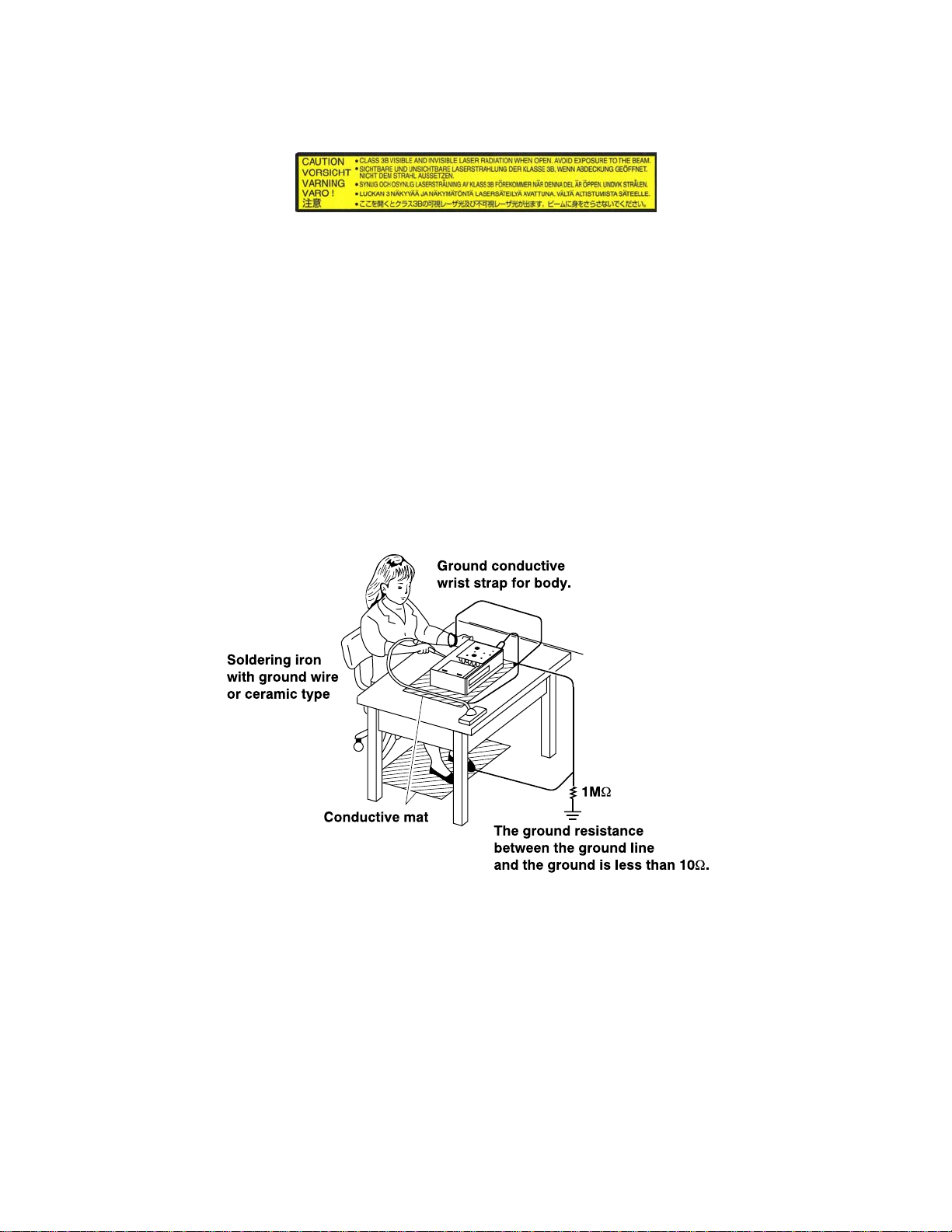
Pickup Head consists of a laser diode that is very susceptible to external static electricity.
Although it operates properly after replacement, if it was subject to electrostatic discharge during replacement, its
life might be shortened. When replacing, use a conductive mat, soldering iron with ground wire, etc. to protect the
laser diode from damage by static electricity.
And also, the LSI and IC are same as above.
Manufactured under license from Dolby Laboratories. “Dolby” and the double-D symbol are trademarks of Dolby Laboratories.
·
Manufactured under license from Digital Theater Systems, Inc. U.S. Pat. No’s. 5,451,942; 5,956,674; 5,974,380; 5,978,762; 6,226,616;
·
6,487,535 and other U.S. and world-wide patents issued and pendling.
“DTS” and “DTS Digital Surround” are registered trademarks of Digital Theater Systems, Inc.
Copyright 1996, 2003 Digital Theater Systems, Inc. All Rights Reserved.
HDMI, the HDMI logo and High-Definition Multimedia Interface are trademarks or registered trademarks of HDMI Licensing LLC.
·
SHARC is a registered trademark and Melody is a trademark of Analog Devices, Inc.
·
All other brand and product names mentioned in this manual are trademarks and/or registered trademarks of their respective holders.
·
Page 4
SAFETY NOTICE
SAFETY PRECAUTIONS
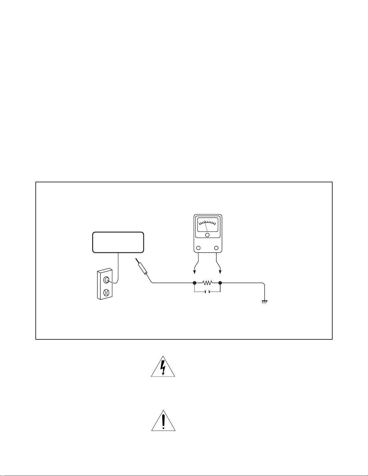
LEAKAGE CURRENT CHECK
Plug the AC line cord directly into a 120V AC outlet (do
not use an isolation transformer for this check). Use an
AC voltmeter, having 5000 Ω per volt or more sensitivity.
Connect a 1500 Ω 10 W resistor, paralleled by a 0.15 μF
150V AC capacitor between a known good earth ground
(water pipe, conduit, etc.) and all exposed metal parts of
cabinet (antennas, handle bracket, metal cabinet
screwheads, metal overlays, control shafts, etc.).
READING SHOULD NOT EXCEED 0.3V
Measure the AC voltage across the 1500 Ω resistor.
The test must be conducted with the AC switch on and
then repeated with the AC switch off. The AC voltage
indicated by the meter may not exceed 0.3 V. A reading
exceeding 0.3 V indicates that a dangerous potential
exists, the fault must be located and corrected.
Repeat the above test with the DVD PLAYER power plug
reversed.
NEVER RETURN A DVD PLAYER TO THE CUSTOMER
WITHOUT TAKING NECESSARY CORRECTIVE AC-
TION.
DVD PLAYER
AC OUTLET
AC VOLTMETER
(5000 Ω per volt
or more sensitivity)
Good earth ground
such as a water pipe,
1500 Ω
10 W
0.15 μF 150V AC
conduit, etc.
Test all exposed metal.
Voltmeter Hook-up for Leakage Current Check
The lightning flash with arrowhead symbol, within an
equilateral triangle, is intended to alert the user to the
presence of uninsulated “dangerous voltage” within the
product’s enclosure that may be of sufficient magnitude to
constitute a risk of electric shock to persons.
The exclamation point within an equilateral triangle is
intended to alert the user to the presence of important
operating and maintenance (servicing) instructions in the
literature accompanying the appliance.
Page 5

1. OPERATING INSTRUCTIONS
2. LOCATION OF MAIN PARTS
2-1. Location of Main Parts
2-2. Location of PC Boards
CONTENTS
SECTION 1
GENERAL DESCRIPTIONS
3. TROUBLESHOOTING
3-1. Standby LED (red) does not lisht.
3-2. LED (green) does not light at power on.
3-3. CPU FAN does not work.
3-4. Indicator does not light. (“WELCOME” does not
light at startup.)
3-5. System does not run. (“WELCOME” displayed and
key operation disabled)
3-6. No picture appears.
3-7. No audio is played back.
3-8. Buzzer does not sound.
3-9. Extension port does not work.
3-10. Front panel key/remote control are disabled.
3-11. Other Symptoms
3-12. Power Circuit Troubleshooting
MEASURING POINTS
PART REPLACEMENT AND ADJUSTMENT PROCEDURES
1. REPLACEMENT OF MECHANICAL PARTS
1-1. Cabinet Replacement
1-1-1. Top Panel and Top Cover
1-1-2. Front Panel and Motor
1-1-3. Sub-chassis
1-1-4. HD-DVD Drive
1-1-5. Rear Panel
1-1-6. Fan
1-2. PC Board Replacement
1-2-1. Digital PC Board
1-2-2. CPU
1-2-3. SO-DIMM
1-2-4. Power PC Board
1-2-5. AV PC Board
1-2-6. Front PC Boards
1. CIRCUIT SYMBOLS AND
SUPPLEMENTARY EXPLANATION
1-1. Precautions for Part Replacement
1-2. Solid Resistor Indication
1-3. Capacitance Indication
1-4. Inductor Indication
1-5. Waveform and Voltage Measurement
1-6. Others
2. PRINTED WIRING BOARD AND
SCHEMATIC DIAGRAM
3. BLOCK DIAGRAMS
3-1. Overall Block Diagram
SECTION 2
2. WIRING CONNECTION DIAGRAM
2-1. Wiring Connection Diagram
2-2. Supplementary Instructions for Reassembling
SECTION 3
SERVICING DIAGRAMS
4. CIRCUIT DIAGRAMS
4-1. Power Supply Circuit Diagram
4-2. Front Circuit Diagram
4-2-1. PWR-SW Circuit Diagram
4-2-2. USB Circuit Diagram
4-2-3. Front-MAIN Circuit Diagram
4-2-4. Door-Detect Circuit Diagram (HD-XA1)
4-2-5. Motor Circuit Diagram (HD-XA1)
4-3. AV Circuit Diagram
4-3-1. Audio Circuit Diagram
4-3-2. Video Circuit Diagram
4-3-3. HDMI Circuit Diagram
5. PC BOARDS
5-1. Front Main PC Board
5-2. PWR-SW PC Board
5-3. Door-Detect PC Board (HD-XA1)
5-4. USB PC Board
5-5. Motor PC Board (HD-XA1)
5-6. AV PC Board
SAFETY PRECAUTION
NOTICE
ABBREVIATIONS
SUPPLEMENT1. Firmware Version Update
SUPPLEMENT2. Error display
SECTION 4
PARTS LIST
1. EXPLODED VIEWS
1-1. Packing Assembly
1-2. Cabinet Assembly 1 (HD-XA1)
1-3. Cabinet Assembly 2 (HD-A1/HD-D1)
1-4. Chassis Assembly
2. PARTS LIST
SUPPLEMENT
Page 6

GENERAL DESCRIPTIONS
SECTION 1
GENERAL DESCRIPTIONS
1. OPERATING INSTRUCTIONS
Please refer to the owner's manual about the contents.
SECTION 1
Page 7
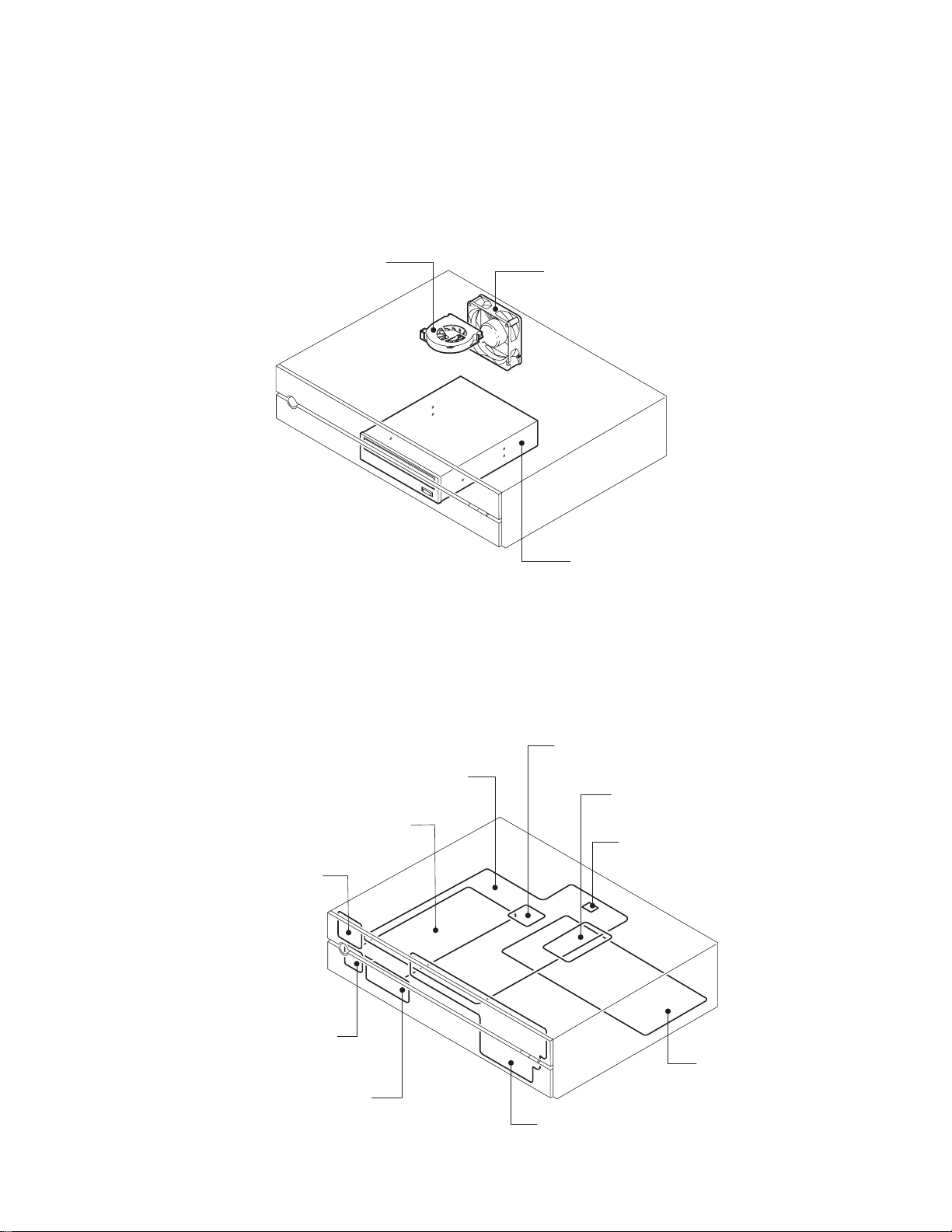
2. LOCATION OF MAIN PARTS
This section describes the location of main parts and PC boards of HD-XA1 as a representative.
2-1. Location of Main Parts
CPU FAN
2-2. Location of PC Boards
FAN
HD-DVD DRIVE
Fig. 1-2-1
Power PC board
PWR-SW PC board
DOOR-DETECT PC board
USB PC board
CPU
Dgital PC board
SO-DIMM
FLASH ROM MODULE
AV PC board
Front Main PC board
Fig. 1-2-2
Page 8
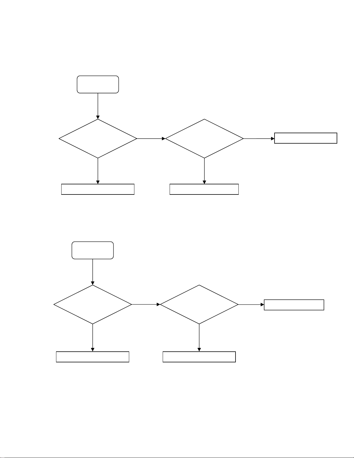
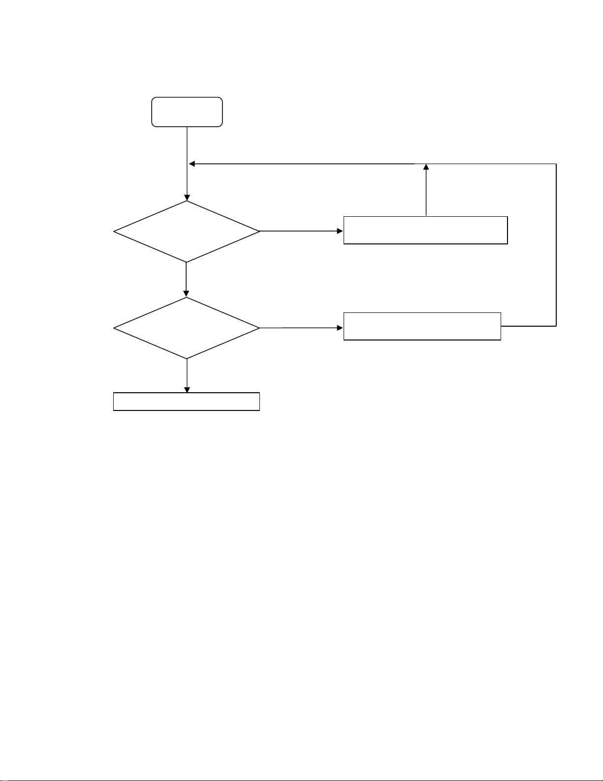
3. TROUBLESHOOTING
3-1. Standby LED (red) does not light.
START (1)
VCC+6V supplied to pin
16 of PJ11 from power
unit?
Replace power unit.
㩷
No
㩷
Yes
㩷
㩷
Yes
LEDOUT1 on pin 6 of
PJ7 is “L”?
No
Failure of digital unit
㩷
㩷
Replace front unit.
㩷
3-2. LED (green) does not light at power on.
LEDOUT1 on pin 6 of PJ7
START (2)
is “H”?
Failure of digital unit
No
㩷
㩷
Yes
PJ7 FFC cable inserted
Replace FFC cable.
correctly?
No
Yes
㩷
Replace front unit.
㩷
㩷
Page 9
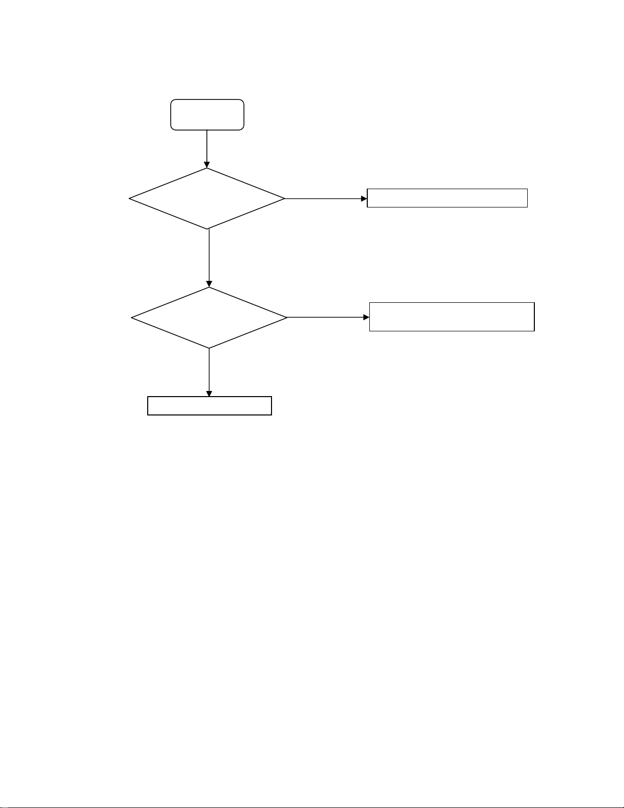
3-3. CPU FAN does not work.
START (3)
Pin 1 of PJ8770
develope 5V±5%?
Power circuit
troubleshooting
No
㩷
Yes
㩷
㩷
Replace CPU FAN unit.
㩷
3-4. Indicator does not light. (“WELCOME” does not light at startup.)
START (4)
㩷
Pin 4 of PJ7 reset and
VFD driver IF bus
working at startup?
1: CS#
2: CLK
3: RESET#
4: DOUT
No
㩷
Failure of digital unit
㩷
Yes
㩷
PJ7 FFC cable inserted
correctly?
No
Replace FFC cable.
㩷
Yes
㩷
Replace front unit or
power unit.
Page 10
3-5. System does not run. (“WELCOME” displayed and key operation disabled)
START (5)
㩷
LED on FLASH ROM
module (PJ15) flashing
about 10 seconds after
power on?
Yes
㩷
Connector (PJ9) of
DVD drive and
power connector
connected
Yes
㩷
Upgrade firmware again.
㩷
(A)
No
No
㩷
Check PJ9 connection
and replace FFC cable.
Not
restored
Replace
DVD drive.
㩷
TP105(P5V) voltage
output correctly?
Yes
LED of FLASH ROM
module (PJ15) lights up after
replacement?
No
Restored
SO-DIMM module
(PJ1420) inserted
correctly?
Yes
No
Power circuit troubleshooting
Yes
Upgrade firmware
again.
㩷
To (A)
No
Insert again or
replace SO-
DIMM?
㩷
㩷
System is restored
after firmware
upgrade?
No
㩷
Failure of digital unit
Yes
㩷
END
㩷
Failure of digital unit
To (5)
Page 11
3-6. No picture appears.
g
START (6)
Before repair, confirm the connection with a TV
x
and the settings of XA1/A1/D1.
㩷
Both components and
HDMI do not output
picture?
Yes
㩷
PJ730 and cable
normal?
Yes
㩷
PJ731 and FFC cable
normal?
Yes
㩷
No
No
No
Check and replace PJ731 FFC cable.
Replace AV unit.
Check and replace PJ730 cable.
Check and replace PJ731 FFC cable.
㩷
PJ732 and FFC cable
normal?
Yes
㩷
Replace AV unit
or
failure of di
ital unit.
㩷
No
Check and replace PJ732 FFC cable.
Page 12
3-7. No audio is played back.
START (7)
Before repair, confirm the connection with a TV
x
and the settings of XA1/A1/D1.
㩷
All analog, digital, and
HDMI audio are not
played back?
Replace AV unit
or
failure of digital unit.
3-8. Buzzer does not sound.
START (8)
[Remote Controller Sound] in
Setup menu selected?
Yes
No
㩷
㩷
㩷
Not selected
Check and replace PJ732㪝FC cable.
Check and replace PJ733 㪝FC cable.
Replace AV unit.
Select [Remote Controller Sound] in
application’s Setup menu.
㩷
Selected
PJ7 and FFC cable normal?
Yes
Failure of digital unit
㩷
No
㩷
㩷
Check and replace PJ7㩷㪝FC cable.
Replace front unit.
㩷
Page 13
3-9. Extension port does not work.
r
START (9)
Neither right port nor
left port works?
Device to be connected is
supported?
Yes
Yes
㩷
㩷
㩷
No
Eitherone port
does not work.
No
Check and replace PJ14 cable o
replace front USB unit.
Check with the device supported by
HD-XA1/A1/D1.
㩷
㩷
Failure of digital unit
㩷
Page 14
3-10. Front panel keys/remote control are disabled.
START (10)
Front LED lighting?
PJ7 connected correctly?
Failure of digit unit
Yes
Yes
㩷
㩷
㩷
㩷
No
No
Change power unit.
Check and replace PJ7㩷㪝FC cable.
Replace front unit.
㩷
㩷
3-11. Other Symptoms
Improper LAN connection
x
LAN depends on the quality of the environment and lines to which LAN is connected. Check the main unit as well as
network settings, cables, and connected devices.
Improper CONTROL pin connection
x
Use a serial cross cable to connect the unit to a PC.
Check the above. However, if the problem still remains, the digital unit may be faulty.
Page 15
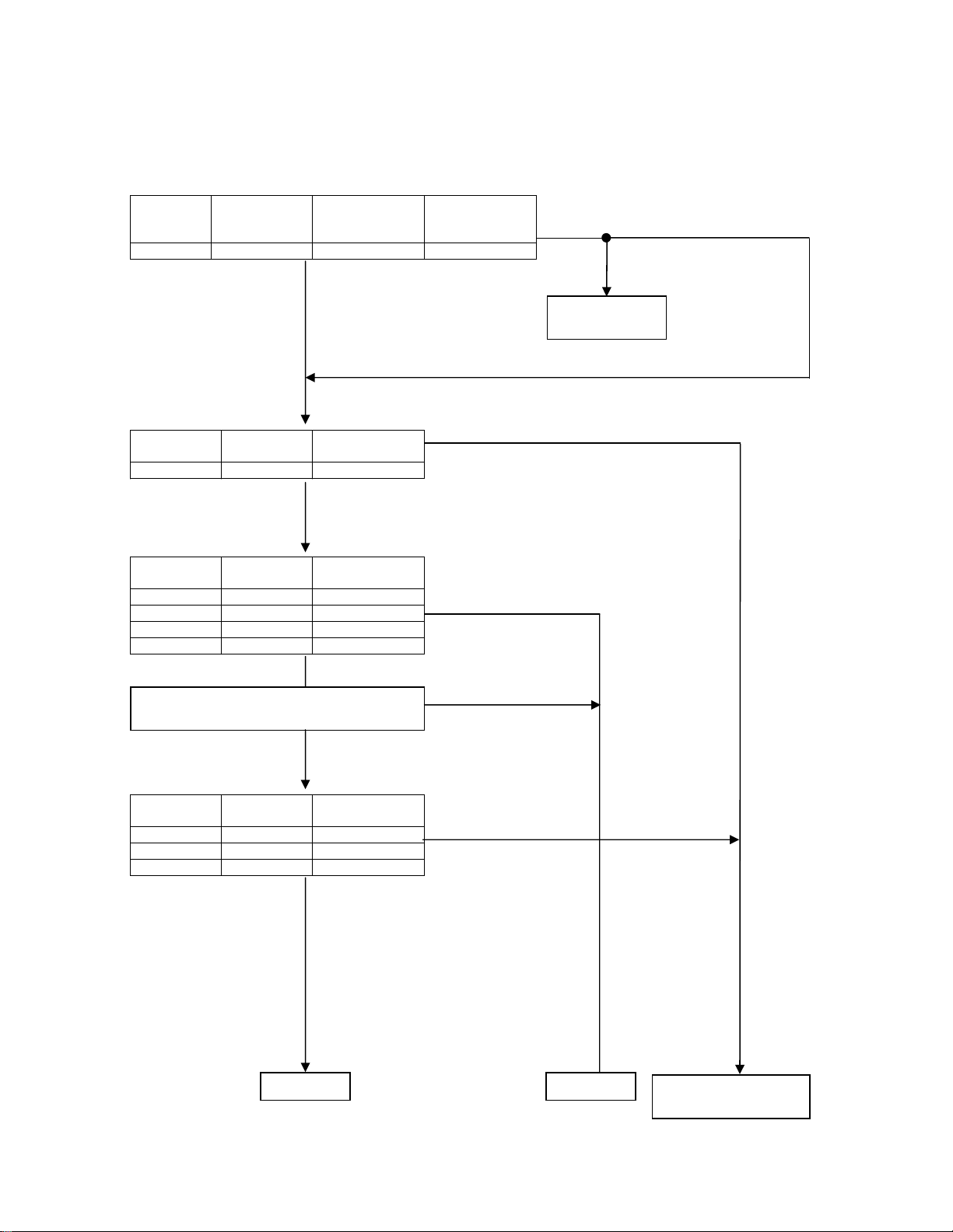
3-12. Power Circuit Troubleshooting
r
r
RTC backup voltage
Power
R3V TP113 2.0-3.0V
Measuring
point
EVER system voltage
Power unit output
Power
PS5VSB TP159 5.5-6.5V
EVER system voltage
M/B REG output, etc.
Power
M5V TP115 4.75-5.25V
M3V TP114 3.13-3.47V
MM5V TP135 4.5-5.0V
MS5V C842-2PIN 4.75-5.25V
Power unit ON/OFF control signal check
PS_ON(Pin 1 of PJ12)
Measuring
point
Measuring
point
Output voltage
range
(AC OFF)
Yes
Output voltage
range
Output voltage
range
Yes
㩷
Yes
㩷
㩷
㩷
Output voltage
range
(AC ON)
3.4-3.0V
NoNo
No
“H”
No
Incorrect voltage at
AC OFF
Battery(BT1)
erro
㩷
Incorrect voltage
at AC ON
Power system voltage
Power unit output
Power
PS12VDC TP160 11.4-12.6V
PS5VDC TP165 4.75-5.25V
PS3VDC TP164 3.13-3.47V
Measuring
points
To (B)
“L”
㩷
Output voltage
range
Yes
㩷
㩷
No
To (C)
㩷
Failure of harness
power unit
and/o
㩷
Page 16
Power system voltage
Power unit output
Power
2R6-P2V TP109 2.5–2.7V
1R2-P1V TP112 1.19–1.26V
2R5-P2V TP108 2.40–2.60V
P5V TP105 4.75–5.25V
1R25-P1V TP162 1.19–1.30V
1R5-P1V TP110 1.45–1.57V
P3V TP107 3.13–3.47V
VID1R2-P1V TP166 1.19–1.26V
1R8-P1V C121-2PIN 1.71–1.89V
VPL3R3-P1V IC560-2/3PIN 3.13–3.47V
APL3R3-P3V C577-2PIN 3.13–3.47V
PCOREV TP111 1.2–1.3V
To (B)
Measuring
points
㩷
Output
voltage range
Yes
㩷
To (C)
㩷
No
Failure of digital unit END
Page 17
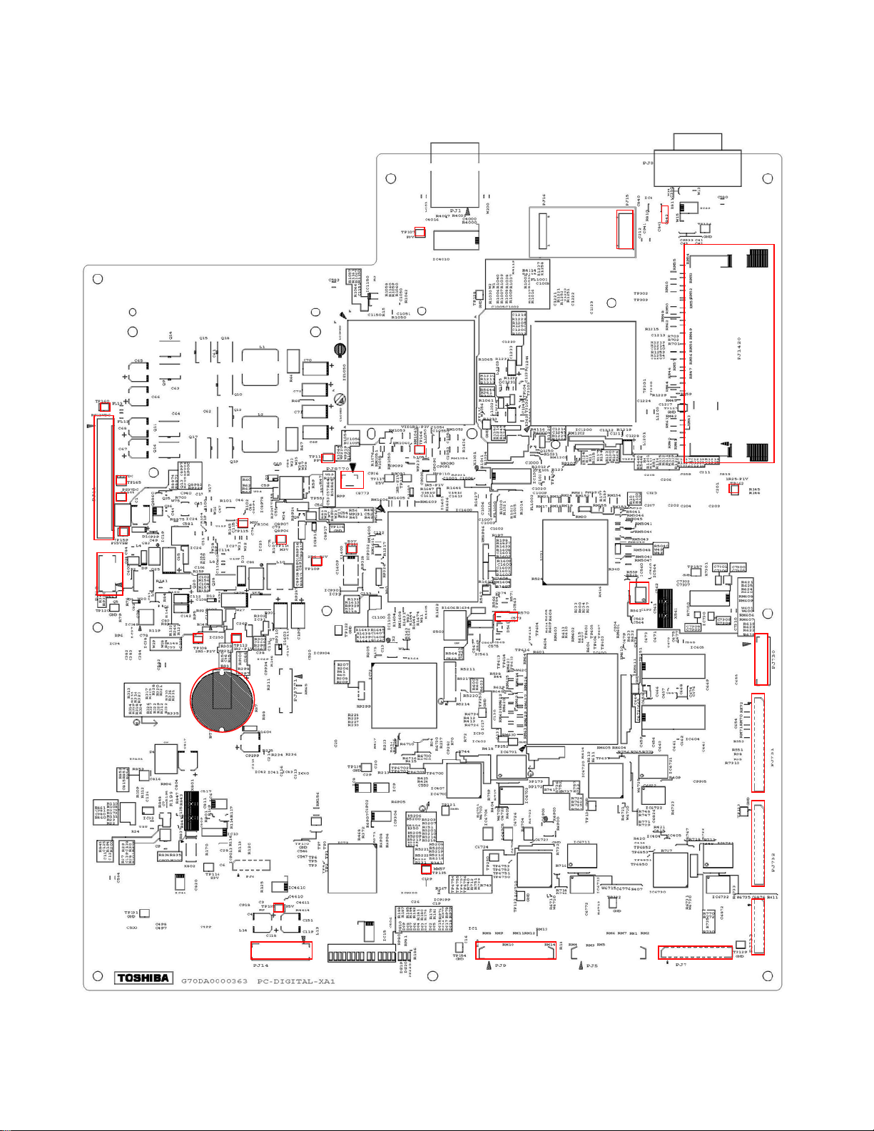
MEASURING POINTS
Fig. 1-4-1 Digital Unit (Top Side)
TP16
PJ1
PJ1
TP16
TP16
TP15
TP11
TP11
TP10 TP11
TP11
TP10
PJ877
TP11
TP10
TP16
C577
PJ15
C842
PJ1420
TP16
IC560
PJ730
BT1
TP13
TP10
PJ14 PJ9 PJ7
PJ731
PJ732
PJ733
Page 18
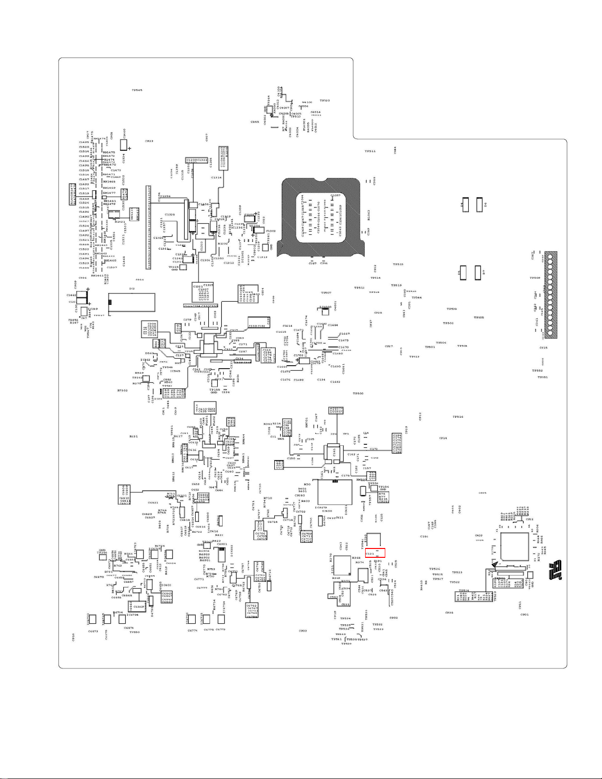
Fig. 1-4-2 Digital Unit (Bottom Side)
C121
Page 19
SECTION 2
PART REPLACEMENT AND
ADJUSTMENT PROCEDURES
CAUTIONS BEFORE STARTING PART REPLACEMENT
Electronic parts are susceptible to static electricity and may be easily damaged, so do not forget to ground as required.
Many screws are used inside the unit. To prevent the screws from missing or dropping, etc. always use magnetized
screwdriver in servicing. Several kinds of screws are used and some of them need special cautions. That is, take care of
the tapping screws securing molded parts and fine pitch screws used to secure metal parts. If they are used improperly,
the screw holes will be easily damaged and the parts can not be fixed.
This section describes how to replace the parts of HD-XA1 as a representative.
ADJUSTMENT PROCEDURES
PART REPLACEMENT AND
1. REPLACEMENT OF MECHANICAL PARTS
1-1. Cabinet Replacement
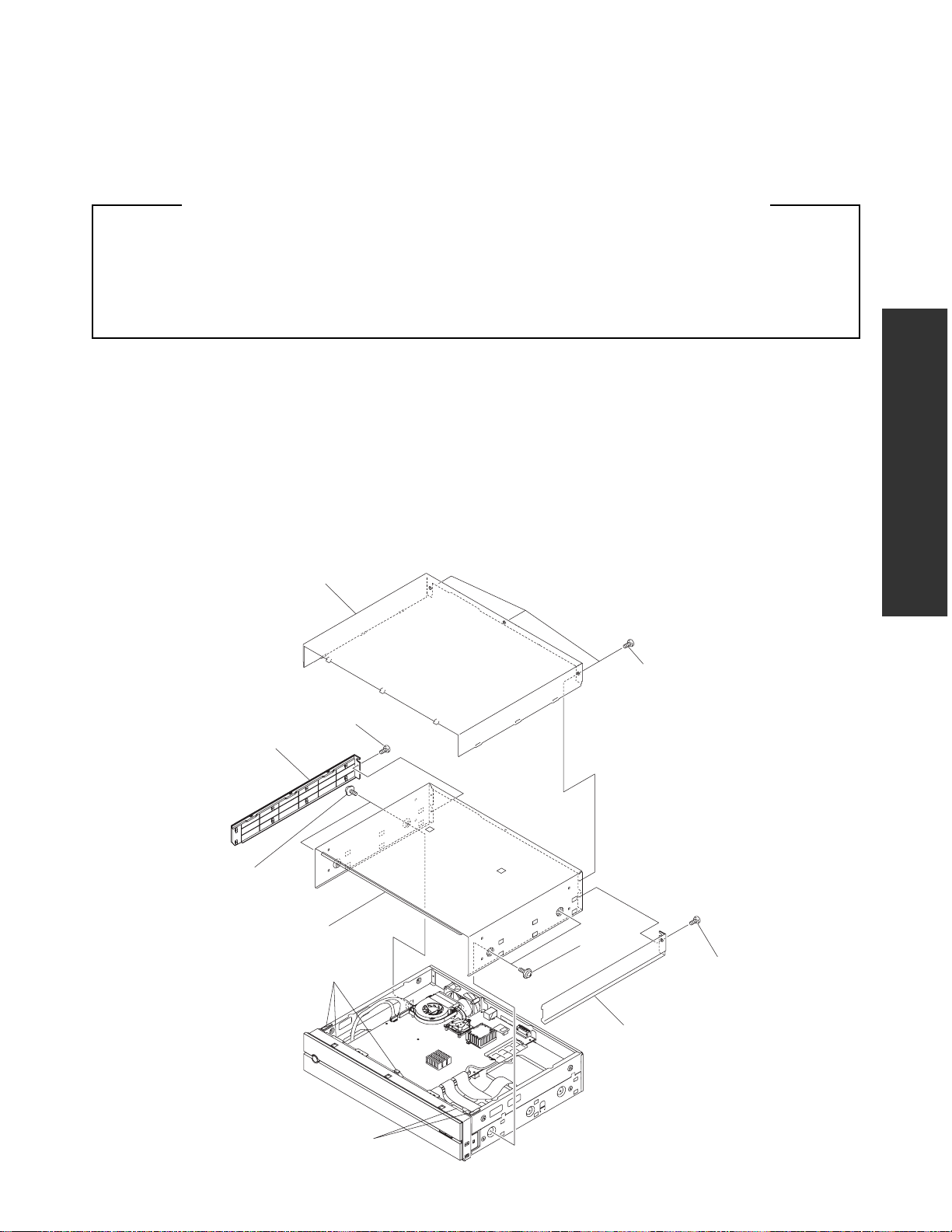
1-1-1. Top Panel and Top Cover
1. Remove two screws (1), then remove the side panel L (2) and side panel R (3).
2. Remove three screws (4), then remove the top panel (5).
3. Remove four screws (6), then remove the top cover (7).
Top panel (5)
Screws (1)
Side panel L (2)
SECTION 2
Screws (4)
Screws (6)
Top cover (7)
Gasket
Gasket
Screws (6)
Screws (1)
Side panel R (3)
Fig. 2-1-1
Page 20

1-1-2. Front Panel and Motor
1. Remove the top panel and top cover. (Refer to item 1-1-1.)
2. Remove the screw (1), two screws (2), three screws (3), and the screw (4).
3. Remove six claws, then draw the front panel (5).
4. Remove the screw (6), then remove the front panel (5).
5. Disconnect the connectors (7) and (8) and the flexible cable (9).
6. Disconnect the connector (10).
7. Remove the belt (11).
8. Remove two screws (12), then remove the motor (13) in the arrow direction.
Connector (8)
Screw (6)
Connector (7)
Claws
Screws (3)
Claws
Screw (4)
Gasket
Claws
Front panel (5)
Gasket
Flexible cable (9)
Gasket
Screws
(2)
Screw (1)
Connector (10)
Motor (13)
Screws (12)
Belt (11)
Gear assy
Fig. 2-1-2
Page 21
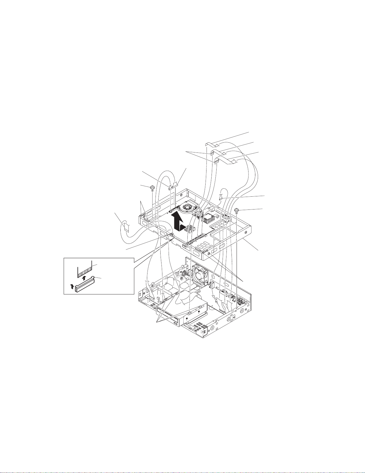
1-1-3. Sub-chassis
1. Remove the top panel and top cover. (Refer to item 1-1-1.)
2. Remove the front panel. (Refer to item 1-1-2.)
3. Disconnect the connectors (1), (2), and (3).
4. Disconnect the flexible cables (4), (5), and (6).
5. Disconnect the flexible cable (7) while raising the claws (8) in the arrow A direction.
6. Remove four screws (9).
7. Move the sub-chassis (10) in the arrow direction, release it from the four claws, and then remove it.
Flexible cable (4)
Flexible cable (5)
Ferrite core
Flexible cable (6)
Connector (1)
Screws (9)
Gasket
Flexible cable (7)
Gasket
Flexible cable
(7)
Claws (8)
A
Claws
Connector (2)
Connector (3)
Screws (9)
Sub-chassis (10)
Gasket
Fig. 2-1-3
Page 22

1-1-4. HD-DVD Drive
Note:
• To replace the HD-DVD drive, enter an encryption key. Contact the service center for details.
1. Remove the top panel and top cover. (Refer to item 1-1-1.)
2. Remove the front panel and sub-chassis. (Refer to items 1-1-2 and 1-1-3.)
3. Disconnect the connector (1).
4. Disconnect the flexible cable (2) while pulling the claws (3) in the arrow A direction.
5. Remove four screws (4), then remove the HD-DVD drive (5).
6. Remove four screws (6), then remove the bracket R (7) and bracket L (8).
Screws (4)
Screws (6)
Bracket L (8)
Connector (1)
HD-DVD drive (5)
Flexible cable (2)
Claws (3)
Flexible cable (2)
A
Screws (4)
Bracket R (7)
Screws (6)
Fig. 2-1-4
Page 23

1-1-5. Rear Panel
1. Remove the top panel and top cover. (Refer to item 1-1-1.)
2. Remove six screws (1), screw (2), and three screws (3), then remove the rear panel (4).
3. Remove two screws (5), then remove the fan (6).
4. Remove two screws (7), two hexagonal nuts (8), then remove the AC inlet (9).
Screws (5)
AC inlet (9)
Fan (6)
Screws (3)
Screws (7)
Hexagonal nuts (8)
Gasket
Gasket
Screws (3)
Screw (2)
Screws (1)
Screws (3)
Rear panel (4)
Gasket
Fig. 2-1-5
Page 24

1-1-6. Fan
1. Remove the top panel and top cover. (Refer to item 1-1-1.)
2. Remove the front panel and sub-chassis. (Refer to items 1-1-2 and 1-1-3.)
3. Disconnect the connector (1).
4. Remove two screws (2), then remove the fan (3).
Fan (3)
Connector (1)
Screws (2)
Fig. 2-1-6
Page 25

1-2. PC Board Replacement
1-2-1. Digital PC Board
Note:
• To replace the Digital PC board, enter an encryption key. Contact the service center for details.
1. Remove the top panel and top cover. (Refer to item 1-1-1.)
2. Remove the SO-DIMM (1). (Refer to item 1-2-2.)
3. Disconnect the connectors (2) to (5) and the flexible cables (6) to (9).
4. Disconnect the flexible cable (10) while raising the claws (11) in the arrow A direction.
5. Remove two connector screws (12).
6. Remove nine screws (13), then remove the Digital PC board (14).
The Digital PC board includes a lithium battery.
Cautions :
• Danger of explosion if battery is incorrectly replaced.
Replace only with the same or equivalent type.
Connector (2)
Connector (3)
Screws (13)
Screws (13)
SO-DIMM (1)
Connector (4)
Flexible cable (10)
Ferrite core
Flexible
cable (10)
Claws (11)
A
Gasket
Flexible cable
(9)
Gasket
Digital PC board (14)
Connector (5)
Flexible cable (6)
Ferrite core
Flexible cable (7)
Flexible cable (8)
Connector screws (12)
Fig. 2-1-7
Page 26

1-2-2. CPU
1. Remove the top panel and top cover. (Refer to item 1-1-1.)
2. Remove the SO-DIMM (1). (Refer to item 1-2-2.)
3. Disconnect the connector (1).
4. Remove two screws (2), then remove the CPU fan (3).
5. Remove three screws (4), then remove the heatsink bracket (5).
6. Remove the heatsink (6).
7. Turn clockwise the lock screw (8) of the CPU socket 180 degrees, then remove the CPU (7).
Note:
• When installing the CPU, orient it correctly.
• When assembling, clean and install the heat sink and the CPU fan, removing dust from them.
• When installing the heat sink bracket, be careful of the order of installation.
(In the order of numbers marked on the heatsink bracket.)
• Apply evenly the silicon grease:GFC001F1(part code: P000468790) to the die (14mm square) of CPU.
(The amount of silicon grease is quantity-managed to 0.2g.)
Screws (4)
3
1
2
CPU fan (3)
Heatsink (6)
CPU (7)
Screws (2)
Connector (1)
Heatsink bracket (5)
Marking
Silicon grease coating
(14mm square, 0.2g)
CPU socket
Fig. 2-1-8
CPU socket
Lock screw (8)
Lock
Unlock
Page 27

1-2-3. SO-DIMM
1. Remove the top panel and top cover. (Refer to item 1-1-1.)
2. Remove the SO-DIMM (3) in the arrow A direction while extending the board holder claws (2) on the Digital PC board (1)
in the arrow direction.
Note:
• To reinstall the SO-DIMM (3), install it so that its groove (4) fits with the projection (5) of the board holder.
Board holder claws (2)
SO-DIMM (3)
Projection (5)
A
Groove (4)
Digital PC board (1)
Fig. 2-1-9
Page 28

1-2-4. Power PC Board
1. Remove the top panel and top cover. (Refer to item 1-1-1.)
2. Remove the front panel and sub-chassis. (Refer to items 1-1-2 and 1-1-3.)
3. Disconnect the connectors (1) to (7).
4. Remove six screws (8), then remove the power PC board (9).
Connector (1)
Screws (8)
Connector (3)
Connector (2)
Connector (4)
Connector (5)
Ground terminal
Connector (6)
Screws (8)
Connector (7)
Power PC board (9)
Fig. 2-1-10
Page 29

1-2-5. AV PC Board
1. Remove the top panel and top cover. (Refer to item 1-1-1.)
2. Remove the front panel and sub-chassis. (Refer to items 1-1-2 and 1-1-3.)
3. Disconnect the connectors (1) and (2) and flexible cables (3) to (5).
4. Remove the screw (6), and six screws (7).
5. Remove five screws (8), then remove the AV PC board (9).
Flexible cable (3)
Flexible cable (4)
Connector (2)
Connector (1)
Screws (8)
AV PC board (9)
Flexible cable (5)
Screws (8)
Fig. 2-1-11
Screw (6)
Screws (7)
Page 30

1-2-6. Front PC Board
1. Remove the top panel and top cover. (Refer to item 1-1-1.)
2. Remove the front panel. (Refer to item 1-1-2.)
3. Disconnect the connector (1), remove two screws (2), and then remove the gear assy (3).
4. Remove eight screws (4), then remove the front main PC board (5).
5. Remove four screws (6), then remove the PWR-SW PC board (7).
6. Remove two screws (8), then remove the DOOR-DETECT-SW PC board (9).
7. Remove two screws (10), then remove the USB PC board (11).
8. Disconnect the flexible cables (12) and (13) and connectors (14) to (16).
Note:
• When installing the Door-Detect-SW board, orient it correctly.
Be sure to connect the connector
with a mark to the USB PC board
when reassembling.
Connector (14)
Screws (8)
DOOR-DETECT-SW
PC board (9)
Front panel (1)
PWR-SW
PC board (7)
Connector (15)
Screws (6)
Flexible cable (13)
Front main PC board (5)
Flexible cable (12)
Screws (10)
USB PC board (11)
Fig. 2-1-12
Connector (1)
Screws (4)
Connector (16)
Screws (2)
Door open/
close drive (3)
Page 31

2. WIRING CONNECTION DIAGRAM
This section describes the wiring connection diagram of HD-XA1 as a representative.
2-1. Wiring Connection Diagram
After the servicing is complete, return the wiring to its original state by using the diagram below as a reference.
B A
D
W103
W102
Power PC board
DOOR-DETECT
PC board
E
(HD-XA1)
PRW-SW PC board
I
(HD-A1/D1)
FAN
USB
PC board
F
W005
W107
HD-DVD DRIVE
Dgital PC board
Front Main PC board
AV PC board
C
(HD-XA1)
W004
W106
W003
(HD-A1/D1)
H
There is no tape
in HD-A1 and D1
W109
W007
W002
E
(HD-XA1)
G
: Flexible cable
: Tape
Fig. 2-2-1
Page 32

2-2. Supplementary Instructions for Reassembling
A. W106
Fix W106 to the sub-chassis under the SO-DIMM with tape so as to insert W106 into the gap under the sub-chassis.
Fig. 2-2-2
B. LAN connector
Check that the conductive tape on the shield case of the LAN connector adheres properly when reassembling.
Fig. 2-2-3
Page 33

C. Front panel (door and open/close key) (HD-XA1)
Check that insulating tape is stuck on the back of the door and open/close key on the front panel when reassembling.
Fig. 2-2-4
D. Arranging ground wire (between USB board and AV board)
Fasten the ground wire together with other wires using a cable tie to keep it away from the primary circuit of the power
board.
Fig. 2-2-5
E. Shaft brackets of electric door (HD-XA1)
Check that gaskets are attached to the shaft brackets of the electric door at the lower part (right and left sides) on the
back of the front panel when reassembling.
Fig. 2-2-6 Fig. 2-2-7
Page 34

F. W107
Check that a ferrite core is attached to W107 when reassembling.
Fig. 2-2-8
G. W106 (HD-A1/D1)
Check that a ferrite core is attached to W106 when reassembling.
H. Tape (HD-A1/D1)
There is no tape in HD-A1 and D1 when reassembling.
Fig. 2-2-9
Fig. 2-2-10
Page 35

I. Fixing of earth leads of W105 and W110(HD-A1/D1)
W105 (50mm) in a hole (W102) for the earth lead on the USB PC board from the component side and solder W105 on the
solder side.
W105
Fig. 2-2-11
Draw out W105 from the upper side of USB PC board toward you and connect W105 with W110.
Fix W110 in the same manner as is done on the HD-XA1.
W105
W105
W110
W110
Fig. 2-2-12 Fig. 2-2-13
Page 36

SECTION 3
SERVICING DIAGRAMS
1. CIRCUIT SYMBOLS AND SUPPLEMENTARY EXPLANATION
1-1. Precautions for Part Replacement
• In the schematic diagram, parts marked (ex.
F801) are critical part to meet the safety regulations, so
always use the parts bearing specified part codes (SN)
when replacing them.
1-2. Solid Resistor Indication
Unit None ........... Ω
K ........... kΩ
M ........... MΩ
Tolerance None ........... ±5%
B ........... ±0.1%
C ........... ±0.25%
D ........... ±0.5%
F ........... ±1%
G ........... ±2%
K ........... ±10%
M ........... ±20%
Rated Wattage (1) Chip Parts
None .........1/16W
(2) Other Parts
None .........1/6W
Other than above, described in the Circuit Diagram.
Type None ........... Carbon film
S ........... Solid
R ........... Oxide metal film
M ........... Metal film
W ...........Cement
FR ........... Fusible
• Using the parts other than those specified shall violate
the regulations, and may cause troubles such as
operation failures, fire etc.
Eg. 1
100k
Rated Wattage Type Tolerance
Fig. 3-1-1
SERVICING DIAGRAMS
1-3. Capacitance Indication
Symbol
Unit None ........... F
Rated voltage None ........... 50V
Tolerance (1) Ceramic, plastic, and film capacitors of which
Temperature characteristic None ........... SL
(Ceramic capacitor) For others, temperature characteristics are
Static electricity capacity Sometimes described with abbreviated letters as
(Ceramic capacitor) shown in Eg. 3.
+
........... Electrolytic, Special electrolytic
NP
........... Non polarity electrolytic
........... Ceramic, plastic
M
........... Film
........... Trimmer
μ ........... μF
p ........... pF
For other than 50V and electrolytic capacitors,
described in the Circuit Diagram.
capacitance are more than 10 pF.
None ........... ±5% or more
B ........... ±0.1%
C ........... ±0.25%
D ........... ±0.5%
F ........... ±1%
G ........... ±2%
(2) Ceramic, plastic, and film capacitors of which
capacitance are 10 pF or less.
None ........... more than ±5 pF
B ........... ±0.1 pF
C ........... ±0.25 pF
(3) Electrolytic, Trimmer
Tolerance is not described.
described. (For capacitors of 0.01 μF and
no indications are described as F.)
Eg. 2
100μ
Temperature
response
Rated
voltage
Tolerance
Fig. 3-1-2
Eg. 3
104
4
pF (0.1μF)
10x10
Temperature characteristic
(or Temperature characteristic+
Static electricity capacity tolerance)
Fig. 3-1-3
SECTION 3
Page 37

1-4. Inductor Indication
Unit None ........... Η
μ ........... μH
m ...........mH
Tolerance None ........... ±5%
B ........... ±0.1%
C ........... ±0.25%
D ........... ±0.5%
F ........... ±1%
G ........... ±2%
K ........... ±10%
M ........... ±20%
1-5. Waveform and Voltage Measurement
• The waveforms for CD/DVD and RF shown in the
circuit diagrams are obtained when a test disc is
played back.
• All voltage values except the waveforms are expressed
in DC and measured by a digital voltmeter.
1-6. Others
• The parts indicated with "NC" or "KETU" etc. are not
used in the circuits of this model.
Eg. 4
Type name
Fig. 3-1-4
Eg. 5
10μ
Type Tolerance
Fig. 3-1-5
Page 38

memo
W001 FFC-5P-L110 (FRONT-POWER SW)
W002 FFC-22P-L140 (Digital-FRONT)
W003 FFC-30P-L190 (Digital-AV)
memo
W004 FFC-25P-L300 (Digital-AV)
W005 FFC -40P-L290 (Digital-HD DRIVE)
W007 FFC-16P-L300 (Digital-AV)
W101 WIRE-8P-L240 (POWER-FRONT)
S2B-PH-K-S
W109
W109
CN102
8
EVER +5V
7
FL_5V
6
GND
F-
5
4
F+
Vkk
3
S8B-PH-K-S
GND
2
MOTOR+5V
1
52807-2210
FRONT MAIN PCB
GND
W108
Board-in (SJN)
W108
S3B-PH-K-S
CN106
SENSOR1
SENSOR2
52806-0510
123
LEADS
CABLE
123
GND
CN108
SENSOR1
SENSOR2
52807-0510
(HD-XA1)
DOOR DETECT PCB
W102 WIRE-4P-L370 (POWER-DIGITAL)
W103 WIRE-16P-L230 (POWER-DIGITAL)
W104 WIRE -8P-L300 (POWER-AV)
W105 WIRE-4P-L200 (POWER-DRIVE)
W106 SHILD-ZHR-CABLE-9P-L180 (Digital-AV)
W107 WIRE-USB-8P-L160 (Digital-USB)
W108 WIRE-3P-L150 (FRONT-DOOR DETECT)
W109 WIRE-2P-L140 (FRONT-MOTOR)
W201 WIRE-ACPWR-2P-L70 (POWER-AC INLET)
VS0
VS1
VS2
VS3
GND
VCLKA
CNX02
123456789
(HD-XA1)
MOTOR PCB
MOTFWD
MOTRWD
3456789
LEADS
MOTRWD
MOTFWD
CN103
NC
NC
REMDATA
GND
GND
MOTVREF
MOTRWD
MOTFWD
SENSOR2
SENSOR1
CASE OPEN
EJECTKEY
AD_KEY2
AD_KEY1
POWERKEY
LEDOUT2
LEDOUT1
BUZZER
PNLRESET
PNLDIN
PNLCLK
PNLSTB
GND
E+5V
54321
W001
1 112 22345
GND
E+5V
Board-in (SJN)
LEDOUT1
POWRKEY
LEDOUT1
POWRKEY
CABLE
1
2
3
4
5
6
7
8
9
10
11
12
13
14
15
16
17
18
19
20
21
22
GND
GND
FRONT PANEL I/F
FFC
CN100
W002
FFC
VS0
VS1
VS2
VS3
GND
VCLKA
PJ731
PJ7
NC
22
NC
21
20
REMDATA
GND
19
GND
18
MOTVREF
17
MOTRWD
16
15
MOTFWD
SENSOR2
14
13
SENSOR1
CASE OPEN
12
11
EJECTKEY
AD_KEY2
10
9
AD_KEY1
POWERKEY
8
7
LEDOUT2
LEDOUT1
6
BUZZER
5
PNLRESET
4
PNLDIN
3
PNLCLK
2
PNLSTB
1
PCB
POWER SW
PJ14
USBFPO-S3N
1234567
USBFPO-S3P
USBFR1-P5VUSBFR1-P5V
GND
GND
USBFP1-S3N
USBFP1-S3P
Fig. 3-2-1
W104
1
GND
GND
GND
GND
E+5V
Vcc+5V
VEE-12V
CNX04
VCC+12V
HD VIDEO IF
SHIELD
CNX01
LVDS0-
LVDS0+
LVDS1-
LVDS1+
LVDS2-
LVDS2+
LVDS CLK-
LVDS CLK+
CNX05
GND
DAC4_BCLK
DAC4_LRCLK
GND
SDATA3
CLATCH3X
GND
HDMI_BCK
AV PCB
VS4
VS5
VS6
VS7
VS8
GND
GND
GND
HDMI_I2CSDA
HDMI_RESETX
SUVDATA4VS9
SUVDATA5I2CSDA
SUVDATA6I2CSCLK
FFC
SD VIDEO IF
W003
10 10
11 11112 12213 13314 14
15 15
16 16
17 17
18 18
19 19
20 20
VS7
VS8
VS4
VS5
VS6
GND
GND
GND
HDMI_I2CSDA
HDMI_RESETX
SUVDATA4VS9
SUVDATA5I2CSDA
SUVDATA6I2CSCLK
HDINT-P3P
21 21
HDINT-P3P
VHDSEL-P3P
22 22
VHDSEL-P3P
GND
23 23
GND
RESOLUTION1
RESOLUTION2
24 24
25 25
RESOLUTION1
RESOLUTION2
GND
ASP1
ASP2
VMUTE
SEL_I/P
26 26
27 27
28 28
29 29
30 30
GND
ASP1
ASP2
VMUTE
SEL_I/P
GND
GND
GND
BCLK
MCLK
CNX03
123456789
56789
GND
GND
GND
BCLK
MCLK
PJ732
GND
LRCLK
SDATA0
GND
LRCLK
SDATA0
GND
IEC958
SDATA4
SDATA2
SDATA1
FFC
10 10211 11312 12413 13514 14615 15716 16817 17
GND
IEC958
SDATA1
SDATA2
SDATA4
HDMI_LRCLK
GND
HDMI_DATA0
HDMI_DATA1
HDMI_DATA2
HDMI_DATA3
GND
NC
GND
CCLK
PWON
AMUTE
CDATA
CLATCH0X
CLATCH1X
CLATCH4X
CLATCH2X
AVRESETX
W004
AUDIO VIDEO IF 1
18 18
19 19
20 20
21 21122 22223 23
GND
CCLK
PWON
CDATA
AMUTE
CLATCH0X
CLATCH1X
CLATCH2X
CLATCH4X
AVRESETX
PJ730
1
1
GND
GND
2
2
LVDS0-
3
3
LVDS0+
4
4
LVDS1-
5
5
LVDS1+
6
6
LVDS2-
7
7
LVDS2+
8
8
LVDS CLK-
LVDS CLK+
9
9
W106
PJ733
GND
1
1
2
2
DAC4_BCLK
3
3
DAC4_LRCLK
4
4
GND
5
5
SDATA3
CLATCH3X
6
6
FFC
GND
7
7
HDMI_BCK
8
8
HDMI_LRCLK
9
9
GND
10
10
HDMI_DATA0
11
11
HDMI_DATA1
12
12
HDMI_DATA2
13
13
HDMI_DATA3
14
14
GND
15
15
AUDIO VIDEO IF 2
NC
16
16
W007
EXTCLK
MRPDAC
25
24
24
25
EXTCLK
MRPDAC
DIGITAL PCB
FAN
CPU
LEADS
CABLE
5V
GND
8
3V
GND
PJ8770
GND
GND
PJ12
BU_5V
P.ON sig
123
4
+12V
+12V
PJ11
1234567
+5V
GND
GND
GND
GND
GND
GND
GND
GND
+12V
+12V
+3.3V
+3.3V
9
8
10
13
GND
DASP-
CS1-
CS0-
DA2
DA2
PDIAG-/CBLID-
DA1-
IOCS16-
INTRQ
GND
DMACK-
CSEL
IORDY
GND
DIOR-
GND
DIOW-
GND
DMARQ
REMOVED
GND
DD15
DD0
DD14
DD1
DD13
DD2
DD12
DD3
DD11
DD4
DD10
DD5
DD9
DD6
DD8
DD7
GND
Reset-
PJ5
GND
DASP-
CS1-
CS0-
DA2
DA2
PDIAG-/CBLID-
DA1-
IOCS16-
INTRQ
GND
DMACK-
CSEL
IORDY
GND
DIOR-
GND
DIOW-
GND
DMARQ
REMOVED
GND
DD15
DD0
DD14
DD1
DD13
DD2
DD12
DD3
DD11
DD4
DD10
DD5
DD9
DD6
DD8
DD7
GND
Reset-
PJ9
40
39
38
37
36
35
34
33
32
31
30
29
28
27
26
25
24
23
22
21
20
19
18
17
16
15
14
13
12
11
10
9
8
7
6
5
4
3
2
1
40
40
39
39
38
38
37
37
36
36
35
35
PDIAG-/CBLID-
34
34
33
33
32
32
31
31
30
30
29
29
28
28
HD DVD IF
27
27
26
26
25
25
24
24
23
23
22
22
21
21
W005
REMOVED
20
20
19
19
18
18
17
17
16
16
15
15
14
14
FFC
13
13
12
12
11
11
10
10
9
9
8
8
7
7
6
6
5
5
4
4
3
3
2
2
1
1
GND
DASP-
DASP-
CS1-
CS1-
CS0-
CS0-
DA2
DA2
DA2
DA2
PDIAG-/CBLID-
DA1-
DA1-
IOCS16-
IOCS16-
INTRQ
INTRQ
GND
GND
DMACK-
DMACK-
CSEL
CSEL
IORDY
IORDY
GND
GND
DIOR-
DIOR-
GND
GND
DIOW-
DIOW-
GND
GND
DMARQ
DMARQ
REMOVED
ATAPI-FFC-UNT
GND
GND
DD15
DD15
DD0
DD0
DD14
DD14
DD1
DD1
DD13
DD13
DD2
DD2
DD12
DD12
DD3
DD3
DD11
DD11
DD4
DD4
DD10
DD10
DD5
DD5
DD9
DD9
DD6
DD6
W005A
DD8
DD8
DD7
DD7
GND
GND
Reset-
Reset-
GNDGND
40
40
DASP-
39
39
CS1-
38
38
CS0-
37
37
DA2
36
36
DA2
35
35
PDIAG-/CBLID-
34
34
DA1-
33
33
IOCS16-
32
32
INTRQ
31
31
GND
30
30
DMACK-
29
29
CSEL
28
28
IORDY
27
27
GND
26
26
DIOR-
25
25
GND
24
24
DIOW-
23
23
GND
22
22
DMARQ
21
21
REMOVED
20
20
GND
19
19
DD15
18
18
DD0
17
17
DD14
16
16
DD1
15
15
DD13
14
14
DD2
13
13
DD12
12
12
DD3
11
11
DD11
10
10
DD4
9
9
DD10
8
8
DD5
7
7
DD9
6
6
DD6
5
5
DD8
4
4
DD7
3
3
GND
2
2
Reset-
1
1
HD DRIVE
5V(RED)
4
GND(BLACK)
3
GND(BLACK)
2
12V(YELLOW)
1
2. PRINTED WIRING BOARD AND SCHEMATIC DIAGRAM
LEADS
CABLE
W101
SHIELD
CN101
87654
USBFPO-S3N
USBFRO-P5V USBFRO-P5V
USBFPO-S3P
USB_CASE_GND
W107
FRONT USB JOINT
31221
GND GND
GND
S8B-PH-K-S
USBFP1-S3P
USBFP1-S3N
USB PCB
USB_GND
LEADS
CABLE
W102
12314
GND
GND
BU_5V
P.ON sig
CN103
F-
Vkk
F+
GND
GND
FL_5V
CN105
POWER PCB
MOTOR+5V
23415263748
EVER+5V
LEADS
CABLE
W103
9
4
64758
3
10
1111121213
14 14
15 15
16 16
+5V
GND
GND
GND
GND
GND
GND
GND
VCC+12V
GND
+3.3V
+3.3V
VCC+6V VCC+6V
GND
GND
VEE-12V
6
7
8
+12V
+12V
+12V
+12V
CN102
GND
GND
E+5V
Vcc+5V
CN104
253
1
MOTOR GND
MOTOR 12V
CN106
CN101
LEADS
CABLE
2
1
FAN
5V
4
GND
3
GND
2
12V
1
LEADS
CABLE
W105
W201
AC INLET
Page 39

JACK
Down mix
Audio OUTPUT
L/R
Front
YUV
ADA4861
Driver(HD)
OUT
JACK
5.1 ch
Audio OUTPUT
COAXL & OPTICAL
Center/
SW
L/R
L/R
Surround
OUT
HDMI
OUT
Video
D4 OUT
S/CV
OUT
Fig. 3-3-1
256MB
Flash ROM
USB NAND
PJ15
USB I/F (On Board)
(Front)
USB2.0 x 2
LAN RJ45
with Trans
100Base-TX/10Base-T
AV UNIT
ACTIVE
LPF Amp
PCM1755
STEREO DAC1
MCLK
I2S x 4
Buffer
SN74LV244APWR
I2S x 4
MCLK
SPI x 4
CNX03/PJ732
IEC958
ACTIVE
LPF Amp
PCM1755
STEREO DAC2
ACTIVE
LPF Amp
PCM1755
STEREO DAC3
ACTIVE
LPF Amp
PCM1755
STEREO DAC4
HDMI
MCLK
HDMI-I2S
Buffer
SN74LV244APWR
HDMI-I2S
CNX05/PJ733
SiI9030
Transmitter
HDMI-IEC958
HDMI-IEC958
64NB
I2C
HDMI-I2C
CNX02/PJ731,733
(SD)
YUV 8bit
3D-DNR with
SDRAM
YUV 10bit(SD)
ADV7312
216MHz 11bit
Video Encoder
(27MHz)
Pixel clock
+Scaler
CD0041AF
IP Converter
Pixel clock(27MHz)
16bit(HD)
YUV/4:2:2/
Pixel clock
(74.25MHz)
VHD SEL
16bit(HD)
YUV/4:2:2/
Pixel clock
(74.25MHz)
JBE
MM1568A
Video Driver(SD)
Bus SW
SN74CBTLV16211GR
16bit(HD)
YUV/4:2:2/
Bus SW
SN74CBTLV16211GR
Pixel clock
(74.25MHz)
CNX01/PJ730
LVDS
Receiver
LVDS(HD)
DS90CF386
PJ9
Drive
HD-DVD
HD-DVD Drive I/F
DIGITAL UNIT
3. BLOCK DIAGRAMS
3-1. Overall Block Diagram
(HD-XA1)
PJ8
RS232C
EXT.AV CONT
(HD-XA1)
PJ7
DOOR
SENSOR
(HD-XA1)
FRONT UNIT
VFD-CNT
NJU3427F
CN103
LED
IR-RX
MOTOR Drive
FL
KEY_BLOCK
GP1UM261XK0F
MOTOR
AV unit
IEC
Digital unit
POWER
AC-JACK
SUPPLY
FAN
Drive
FRONT
Page 40

Fig. 3-4-1
4. CIRCUIT DIAGRAMS
4-1. Power Supply Circuit Diagram
Page 41

Fig. 3-4-2
4-2. Front Circuit Diagram
4-2-1. PWR-SW Circuit Diagram
Page 42

4-2-2. USB Circuit Diagram
Fig. 3-4-3
Page 43

Fig. 3-4-4
4-2-3. Front-MAIN Circuit Diagram
Page 44

4-2-4. Door-Detect Circuit Diagram (HD-XA1)
Fig. 3-4-5
Page 45

4-2-5. Motor Circuit Diagram (HD-XA1)
Fig. 3-4-6
Page 46

Fig. 3-4-7
4-3. AV Circuit Diagram
4-3-1. Audio Circuit Diagram
Page 47

Fig. 3-4-8
4-3-2. Video Circuit Diagram
Page 48

Fig. 3-4-9
4-3-3. HDMI Circuit Diagram
Page 49

Fig. 3-5-1 Front MAIN PC Board (Top side)
12345678
5. PC BOARDS
5-1. Front MAIN PC Board
A
B
Page 50

Fig. 3-5-2 Front MAIN PC Board (Bottom side)
12345678
A
B
Page 51

A
B
C
134
5-2. PWR-SW PC Board
2 5
Fig. 3-5-3 PWR-SW PC Board (Top side)
D
E
F
Fig. 3-5-4 PWR-SW PC Board (Bottom side)
5-3. Door-Detect PC Board (HD-XA1)
Fig. 3-5-5 Door-Detect PC Board (Top side)
G
Fig. 3-5-6 Door-Detect PC Board (Bottom side)
Page 52

A
B
C
134
5-4. USB PC Board
2 5
Fig. 3-5-7 USB PC Board (Top side)
D
E
F
Fig. 3-5-8 USB PC Board (Bottom side)
5-5. Motor PC Board (HD-XA1)
Fig. 3-5-9 Motor PC Board (Top side)
G
Fig. 3-5-10 Motor PC Board (Bottom side)
Page 53

Fig. 3-5-11 AV PC Board (Top side)
1234567
5-6. AV PC Board
A
B
C
Page 54

Fig. 3-5-12 AV PC Board (Bottom side)
1234567
A
B
C
Page 55

SECTION 4
PARTS LIST
SAFETY PRECAUTION
The parts identified by ! ( ) mark are critical for safety. Replace only with part number specified.
The mounting position of replacement is to be identical with originals.
The substitute replacement parts which do not have the same safety characteristics as specified in the parts list may create
shock, fire or other hazards.
NOTICE
The part number must be used when ordering parts in order to assist in processing, be sure to include the model number
and description.
ABBREVIATIONS
Integrated Circuit (IC)
•
Capacitor (Cap)
•
• Capacitance Tolerance (for Nominal Capacitance more than 10pF)
Table 4-2-1
Symbol
Tolerance %
Symbol
Tolerance %
• Capacitance Tolerance (for Nominal Capacitance 10pF or less)
Symbol
Tolerance pF
Resistor (Res)
•
• Resistance tolerance
Symbol
Tolerance %
B
± 0.1
P
+ 100
0
B
± 0.1
B
± 0.1
C
± 0.25
Q
+ 30
– 10
C
± 0.25
C
± 0.25
D
± 0.5
T
+ 50
– 10
D
± 0.5
Ex. 10pF G = 10pF ± 2pF
D
± 0.5
F
± 1
U
+ 75
– 10
Table 4-2-2
F
± 1
Table 4-3-1
F
± 1
G
± 2
V
+ 20
– 10
G
± 2
G
± 2
J
± 5
W
+ 100
– 10
J
± 5
K
± 10
X
+ 40
– 20
Ex. 10μF J = 10μF ± 5%
K
± 10
M
± 20
Y
+ 150
– 10
M
± 20
N
± 30
Z
+ 80
– 20
PARTS LIST
SECTION 4
Ex. 470ΩJ = 470Ω± 5%
Page 56

1. EXPLODED VIEWS
1-1. Packing Assembly
Z001
Z009
Z010
Z013
Z002
Z006
Z007
Fig. 4-1-1
Page 57

1-2. Cabinet Assembly 1 (HD-XA1)
B310
B330
B300
U003C
1
A001
U003A
W001
3
W101
U003B
W108
2
B335
W109
A330
A341
A300
U003
Fig. 4-1-2
Page 58

1-3. Cabinet Assembly 2 (HD-A1/HD-D1)
B300
U003C
A001
U003A
1
W101
3
2
W001
U003
This figure shows the cabinet
assembly of HD-D1.
Fig. 4-1-3
Page 59

1-4. Chassis Assembly
RHE1
CPUFAN
CPU
W005
g
W107
W002
f
1
BT1
a
b
c
c
b
a
g
d
e
f
2
k
j
W005A
PJ15
h
l
PJ1420
W106
W003
W004
W007
(1)
W105
PWR1
B340
W103
3
k
d
e
W102
W104
j
PWR1A
l
h
FAN1
U002
B340
Fig. 4-1-4
Page 60

Replacement of Digital PC Board
The digital PC board for service use, on which some parts are not mounted, is supplied.
When replacing the digital PC board, mount the parts removed from the former board on a new board.
<Digital PC Board for service use>
<Completed Digital PC Board>
CPU fan
FLASH ROM MODULE
Heatsink MEMORY
CPU
Page 61

2. PARTS LIST
Location
No.
Part No. Description
- MECHANICAL PARTS -
A001 P000461210 PANEL ASSY,FRONT HD-XA1
A001 P000464130 PANEL ASSY,FRONT HD-A1
A001 P000464190 PANEL ASSY,FRONT HD-D1
A300 P000461170 GEAR ASSY
A330 P000461190 MOTOR ASSY
A341 P000461420 DRIVE BELT
B300 P000461410 COVER TOP HD-XA1
B300 P000464160 COVER TOP HD-A1
B300 P000464200 COVER TOP HD-D1
B310 P000461180 PANEL ASSY TOP HD-XA1
B330 P000461510 PANEL SIDE L HD-XA1
B335 P000461520 PANEL SIDE R HD-XA1
B340 P000461160 FOOT KIT 4PCS WITH RUBBER,HD-XA1
B340 P000464110 FOOT KIT HD-A1/D1
FAN1 P000461330 FAN DC D08A-12TS602
W001 P000461460 FFC-5P-L110 FRONT-PWRSW
W002 P000461610 FFC-22P-L140 DIGITAL-FRONT
W003 P000461470 FFC-30P-L190 DIGITAL-AV
W004 P000461480 FFC-25P-L300 DIGITAL-AV
W005 P000461490 FFC-40P-L290 DIGITAL-DRIVE
W007 P000461590 FFC-16P-L300 DIGITAL-AV
W101 P000461600 WIRE-8P-L240 POWER-FRONT
W102 P000461370 WIRE-4P-L370 POWER-DIGITAL
W103 P000461360 WIRE-16P-L230 POWER-DIGITAL
W104 P000461350 WIRE-8P-L300 POWER-AV
W105 P000461500 WIRE-4P-L200 POWER-DRIVE
W106 P000461340 SHIELD-ZHR-9P-L180 DIGITAL-AV
W107 P000461380 WIRE-8P-L160 DIGITAL-USB
W108 P000461390 WIRE-3P-L150 FRONT-DOORSENSOR
W109 P000461400 WIRE-2P-L140 FRONT-MOTOR
W005A P000461260 ATAPI ADAPTER FFC-ATAPI CONV UNIT
Z001 P000461430 CORD POWER UL
Z002 P000461440 REMOCON UNIT SE-R0200,HD-XA1
Z002 P000464150 REMOCON UNIT SE-R0237,HD-A1/D1
Z006 P000458270 OWNERS MANUAL ENGLISH,HD-XA1
Z007 P000458280 OWNERS MANUAL FRENCH,HD-XA1
Z006 P000464170 OWNERS MANUAL ENGLISH,HD-A1
Z007 P000464180 OWNERS MANUAL FRENCH,HD-A1
Z006 P000464210 OWNERS MANUAL ENGLISH,HD-D1
Z007 P000464220 OWNERS MANUAL FRENCH,HD-D1
Z009 P000461540 CABLE AV VISUAL 1P-L1500
Z010 P000461550 CABLE AV AUDIO 2P-L1500
Z013 P000461530 CABLE HDMI JE-6119190803
- ELECTRICAL PARTS -
(1) P000462950 HD-XA1 ASSY DIGITAL-PCB/HD-DVD-DRIVE,HD-XA1
(1) P000464140 HD-A1/D1 ASSY DIGITAL-PCB/HD-DVD-DRIVE,HD-A1/D1
PJ1420 P000461280 SO-DIMM MODULE 1GB
PJ15 P000461290 FLASH MEMORY MODULE 256MB
Page 62

Location
No.
CPU P000461300 CPU MODULE PENTIUM4
CPUFAN P000461320 FAN CPU MCF-TS6512M05
RHE1 P000461570 RHE-MODULE MCF-130P-RHE
BT1 P000461310 LI-BATTERY CR2032-1HF
PWR1 P000461450 POWER UNIT MPN5232XA
PWR1A P000461580 AC-INLET WIRE ACPWR 3P-L70
U002 P000461200 PC BOARD ASSY AV
U003 P000461220 PC BOARD ASSY FRONT MAIN,HD-XA1
U003 P000464120 PC BOARD ASSY FRONT MAIN,HD-A1/D1
U003A P000461230 PC BOARD ASSY POWER SW
U003B P000461240 PC BOARD ASSY DOOR DETECT
U003C P000461250 PC BOARD ASSY USB
Part No. Description
Page 63

SUPPLEMENT
SUPPLEMENT1. Firmware Version Update
We plan to respond to these developments by providing the firmware update.
The latest information will be informed Toshiba customer support on the WEB.
1) Main Firmware
2) HD DVD Drive Firmware
1. HD DVD Player FW Update
To update the firmware, the following procedures are provided.
1) HD DVD based
Internet connection Direct Download to player
2) PC based Download
PC (Download)
3) CD-ROM
CD-ROM (mail)
2. Check Main Firmware version (in detail)
Check Main FW Version by the special Code from the remote control
<Field Service Use only — Do not disclose to users.>
1) Press “ON / STAND BY” on the unit or remote.
2) Press “DISPLAY” -> “1”->“9”->“5”-> “DISPLAY”
3) Main FW version is shown on the unit display as “1-007”.
(ex.) Version 1.007
CD-R making
The first 2 digits(1.0) is disclosed to users.
(The following 2 digits(07) is only use for development.)
This version can be checked from “SETUP” menu also.
3. Firmware Version Check procedure
Check from “SET UP Menu”
1) Press “ON / STAND BY” on the unit or remote.
2) Press “SETUP” button.
3) Select “General” -> “Maintenance”->“Update”.
4) The firmware version is shown on TV display as below.
Update
1.0 / 1.09 / 2.0 O
Press SETUP to begin
down loading update
Cancel
Current FW Version
1.0 / 1.09 / 2.0 O
Main FW Version Drive FW Version
Page 64

5) If select “SETUP”, downloading update will be started.
4. Firmware Update Procedure
(1) Main (or Drive) FW Update by CD-ROM disc
1) Insert Update disc into the unit.
2) Indicate the notice.
-> Select YES & press “OK” button on the remote control.
3) Version update is started. Waiting a few minutes.
4) Tray will be opened and power off automatically.
5) Power On & confirm the FW version.
(2) FW Update from WEB site
From “SETUP” menu, the latest firmware can be downloaded to the unit.
* Refer to Firmware version check procedure.
* Internet always-on broadband connection is needed.
Page 65

SUPPLEMENT2. Error Display
yer
y
)
1. System Error
System Error Code Table
External
error code
0x81xxxxxx Application error
0x83xxxxxx
0x84xxxxxx
0x85xxxxxx
0x4094C000 Fatal error of Advanced Pla
0x4094C002 Application error
0x4094C004 S
0x4094C005 AACS error
0x4094C006 Error from VCP
0x4094C007 Error from GCP
0x4094C008 When SecureAccessControllerFailure occurs
0x4094C009 For VCPFailure
0x4094C00A For PrivateFailure (Do not use it.)
0x4094C00B When ResourceLoadFailure occurs
0x4094C00C When ScriptFailure occurs
0x4094C00D Error occurred at Markup anomaly
0x4094C00F Error from AdvUI
0x4094C0FE Fatal error of advanced Player
0x4094C100 Fatal error of AdvMain
0x4094C1FE Fatal error of AdvMain
0x4094C200 Fatal error of iHD
0x4094C201 AACS error of Load Playlist processing
0x4094C202 Fatal error of AACS processing
0x4094C203 Pla
0x4094C2FE Fatal error of iHD
0x4094C300 Fatal error of SM
0x4094C3FE Fatal error of SMX
0x4094C400 Fatal error of Ecma Script Engine
0x4094C4FE Fatal error of Ecma Script Engine
0x4094C500 Fatal error of VCP
0x4094C502 Incorrect support for PAL/NTSC
0x4094C503 Error related to AACS
0x4094C504 Error of disc content
0x4094C5FE Un-expected error
0x4094C600 Fatal error of GCP
0x4094C601 Use of Pixel Buffer exceeds 4.15M pixels.
0x4094C6FE Fatal error of GCP
Message on OSD English
Application error
Application error
Application error
stem error (such as initialization failure
ylist read-in/Analysis error
Content of error OSD VFD
(Not to be used)
(Returned Value)
X
Cannot play the disc.
Error code : 0x00000000
YES
YES
YES
YES
YES
YES
YES
YES
YES
YES
YES
YES
YES
YES
YES
YES
YES
YES
YES
YES
YES
YES
YES
YES
YES
YES
YES
YES
YES
YES
YES
YES
YES
YES
YES
YES
YES
note:
*OSD is a display of the TV monitor screen.
*VFD is a display of the indicator of the front panel.
ERROR
ERROR
ERROR
ERROR
external error code
external error code
external error code
external error code
external error code
external error code
external error code
external error code
external error code
external error code
external error code
external error code
external error code
external error code
external error code
external error code
external error code
external error code
external error code
external error code
external error code
external error code
external error code
external error code
external error code
external error code
external error code
external error code
external error code
external error code
external error code
external error code
external error code
Japanese
0x00000000
French
Impossible de reproduire le disque.
Code d'erreur : 0x00000000
2. HDMI error
VFD
HDMI ERROR
HDMI ERROR
0 Error related to HDMI connection
1 Error related to HDCP approval
content of error
Page 66

3. Update error
Content of error Message on VFD
When the network connection
is failed
When the network connection
is interrupted
When the software is already
updated
Code Message on VFD Content Cause Remarks
101
VUPERROR101
102
VUPERROR102
103
VUPERROR103
104
VUPERROR104
105
VUPERROR105
106
VUPERROR106
107
VUPERROR107
108
VUPERROR108
109
VUPERROR109
110
VUPERROR110
111
VUPERROR111
112
VUPERROR112
113
VUPERROR113
114
VUPERROR114
115
VUPERROR115
116
VUPERROR116
117
VUPERROR117
118
VUP
ERROR118
119
VUPERROR119
120
VUPERROR120
121
VUPERROR121
122
VUPERROR122
123
VUPERROR123
124
VUPERROR124
125
VUPERROR125
126
VUPERROR126
127
VUPERROR127
128
VUPERROR128
129
VUPERROR129
130
VUPERROR130
131
VUPERROR131
132
VUPERROR132
133
VUPERROR133
134
VUPERROR134
135
VUP
ERROR135
136
VUPERROR136
137
VUPERROR137
138
VUPERROR138
139
VUPERROR139
140
VUPERROR140
141
VUPERROR141
142
VUPERROR142
143
VUPERROR143
144
VUPERROR144
145
VUPERROR145
146
VUPERROR146
147
VUPERROR147
148
VUPERROR148
149
VUPERROR149
150
VUPERROR150
151
VUPERROR151
152
VUP
ERROR152
153
VUPERROR153
154
VUPERROR154
155
VUPERROR155
156
VUPERROR156
157
VUPERROR157
158
VUPERROR158
159
VUPERROR159
160
VUPERROR160
161
VUPERROR161
162
VUPERROR162
163
VUPERROR163
164
VUPERROR164
165
VUPERROR165
166
VUPERROR166
167
VUPERROR167
168
VUPERROR168
169
VUPERROR169
170
VUPERROR
201
VUPERROR201
202
VUPERROR202
203
VUPERROR203
204
VUPERROR204
205
VUPERROR205
206
VUPERROR206
207
VUPERROR207
208
VUPERROR208
209
VUPERROR209
210
VUPERROR210
211
VUPERROR211
212
VUPERROR212
213
VUPERROR213
214
VUPERROR214
215
VUPERROR215
216
VUPERROR216
217
VUPERROR
VUPERROR218
218
VUPERROR219
219
VUPERROR220
220
The following reference.
Initialization error
Initialization error
Initialization error
Finishing process
Finishing process
Version Updated from Disc.
Version Updated from Disc.
Version Updated from Disc.
Version Updated from Disc.
Version Updated from Net.
Version Updated from Net.
Version Updated from Net.
Version Updated from Net.
Version Updated from Net.
Version Updated from Net.
Version Updated from Net.
Version Updated from Net.
Version Updated from Net.
Version Updated from Net.
Version Updated from Net.
Version Updated from Net.
Version Updated from Net.
Version Updated from Net.
Version Updated from Net.
Version Updated from Net.
Version Updated from Net.
Version Updated from USB MEMORY.
Version Updated from USB MEMORY.
Version Updated from USB MEMORY.
Version Updated from USB MEMORY.
Common to read-out
Common to read-out
Common to read-out
Common to read-out
When extracting
When extracting
170
When extracting
When extracting
When extracting
Finishing process
Ciphering process
Ciphering process
217
Japanese English French
Can not find out server.
The download failed. Wait a while
and then try to update the software
again.
The software has already been
updated.
The update process will end.
Illegal arguments at the start-up
Initialization error of SubMicom
Failed to create RAM DISK.
Failed to delete RAM DISK.
Error of finishing process of SubMicom
Failed to open a device.
Failed to read the header information.
Failed to read the data information.
Unmatched checksum
Connection error
Reception error
Improper download information
3 times of unmatched CRC32 value of data file
Transmission ewrror of data download finish
Trasmission error at the download finish
Failed to concatenate files.
Failed to read the header information.
Failed to read the data information.
Unmatched checksum
Transmission error
Disconnection error
Illegal Proxy setting
Error of Proxy connection
3 times of time-over
Files in the server are old.
Time-over of server connection at the request of program information
Failed to mount.
Failed to read the header information.
Failed to read the data information.
Unmatched checksum
Identical version/Version down
Unmatched language
Unmatched hardware
Unmatched user
Error of lock file creation
Error of lock file deletion
Error at extracting a tar
Error at executing postcommand.sh
NG code returned from postcommand.sh
Error at executing sync command
Failed to restore a tar.gz file.
Failed to re-cipher the application.
Message on OSD
Impossible de trouver le serveur.
Le téléchargement a échoué. Attendez un
moment et puis essayez de mettre à jour
le logiciel encore.
Le logiciel a été déjà mis à jour. Le
processus de mise à jour finira.
Finished
Finished
Finished
Finished
Finished
Finished
Finished
Finished
Finished
Finished
Finished
Finished
Finished
Continued
Continued
Finished
Finished
Finished
Finished
Finished
Finished
Finished
Finished
Finished
Finished
Finished
Finished
Finished
Finished
Finished
Finished
Finished
Finished
Finished
Continued
Continued
Finished
Finished
Not set
Finished
Finished
Finished
Page 67

SPECIFICATIONS
Power requirement during operation
Power supply
Mass
External dimension
Signal system
Laser
VIDEO output
S-VIDEO output
COMPONENT output(Y, PB, PR)
ANALOG AUDIO output
DIGITAL AUDIO OUTPUT (BITSTREAM/PCM jack)
LAN port
EXTENSION port
RS-232C connector (HD-XA1)
HDMI output
Remote control
Operating conditions
Clock accuracy
• This model complies with the above specifications.
• Designs and specifications are subject to change without notice.
• This model may not be compatible with features and/or specifications that may be added in the future.
• The Illustrations and screens described in this manual may be exaggerated or simplified for easy recognition and may be slightly different from the
actual unit.
90.0W
120V AC, 60 Hz
HD-XA1: 8.9kg, HD-A1•D1: 7.4kg
HD-XA1: Width 437 x Height 115 x Depth 354mm, HD-A1•D1: Width 430 x Height 103 x Depth 353mm
Standard NTSC Color TV system
Semiconductor laser, Wavelength : 405nm/650nm/780nm
1.0Vp-p (75Ω), Sync signal negative, Pin jack x 1 system
(Y) 1.0Vp-p (75Ω), Sync signal negative,
(C) 0.286Vp-p (75Ω) 1 at rear
Mini DIN4 Pin x 1 system
Y output (green), 1.0Vp-p (75Ω), Sync signal negative, Pin jack x 1 system
PB, PRoutput (blue, red), 0.7Vp-p (75Ω), Pin jack x 1 system each
2.0V (rms), 2.2kΩ or below, pin jack (L, R) x 2 systems
2.0V (rms), 2.2kΩ or below, pin jack, Pin jack x 6
Optical connector x 1 system
Coaxial pin jack x 1 system, 0.5Vp-p (75Ω)
100BASE-TX/10BASE-T x 1
EXTENSION port x 2 systems
DSUB 9 pin
19 pin
Wireless remote control (HD-XA1: SE-R0200, HD-A1•D1: SE-R0237)
Temperature: 41°F~95°F (5°C~35°C)
Position: Horizontal
Quartz (monthly deviation: approximately ±30 seconds)
Page 68

1-1, SHIBAURA 1-CHOME, MINATO-KU, TOKYO 105-8001, JAPAN
 Loading...