

Page 1
DIGITAL HIGH DEFINITION RECEIVER
INTRODUCTION
STARTUP GUIDANCE
10
15
HD-C26H
OWNER'S MANUAL
FUNCTIONS
APPENDICES
27
49
©2005 Toshiba Corporation
1
DVB registration identification reference number: 3765.
Trade Mark of the DVB Digital Video Broadcasting Project
(1991 to 1996)
Page 2

PRECAUTIONS
Changes or m odifications t o this equipm ent not expressl y authorised or approved b y Toshiba c ould vo id the
ult in f ire or electric shock. Inspect the po wer cord for d amage. If
WARNING: TO PREVENT FIRE OR SHOCK HAZARD, DO NOT EXPOSE THIS APPLIANCE TO RAIN OR
MOISTURE.
TO PREVENT ELECTRIC SHOCK, DO NOT OPEN THE COVER. REFER SERVICING TO
QUALIFIED PERSONNEL ONLY.
This unit is not disconnected fr om the AC power source as long as it is connected to the wall outlet , even if the
unit itself is in standby mode.
NOTE
The rating label and the safety cauti on are on the rear of the unit.
product warranty and/or cause dam age to the product.
In order to continue to get the m aximum performance from your receiver:
• Make sure that it is set up properl y.
• Have it regularly inspected by qualif ied service personnel.
• Make sure that all family mem bers learn to operate it properly.
In particular: To prevent electric s hock, instruct children not to insert objects into the receiver’s holes or slots.
POWER CORD CAUTIONS
• When plugging in or unplugging th e power cord, hold it by the plug. D o not unplug it by pulling on the cord.
• Do not touch the cord with wet hands as t his could cause electrical shock or short.
• Do not place furniture, etc., on t op of the power cord.
• Do not tie up the power cord, or con nect a different power cord.
• Route the power cord so that it is n ot stepped on, or tripped over.
• Using a dam aged power c ord could res
damaged, consult your nearest T OSHIBA service centre.
SAFETY MEASURES ON PROPER USAGE
Pay attention to the following items when using this unit. Failure to do so may result in electric shock or damage
to the unit.
1. Connect the power plug to AC 100-24 0V 50/60Hz.
2. Unplug the power c ord from the receiver before connecting any other equipment, especially the TV
antenna. Connect all equipm ent to the receiver before plugging an y power cords to the power source.
3. Be sure your TV antenna i s not locat ed near overhead po wer lines, or where it m ight fall into any po wer
lines. Also be careful to avoid touchi ng any such power lines when insta lling the TV antenna.
4. Do not attempt to modif y the unit.
5. If you hear a strange sound or notice s moke coming f rom the unit or feel that the unit is too hot to t ouch,
turn the power off immediatel y, unplug the power cord, and consult with your local sales outlet.
6. Do not insert m etal objects, paper or liquids in to the unit through th e ventilation openings, etc. This could
result in fire or electric shock . In the event s omething is inserted inside, turn the power off, unplug the
power cord and consult your local sa les outlet.
7. Do not place objects that ma y block the ventilation openings of the unit s uch as a piece of cloth.
8. Do not p lace v ases, bottles, containers, naked flame sources such as lighted candles etc., on top of or
near this unit.
9. When transporting, do not vibrate or shake the unit. This ma y result in damage or faulty operation.
10. If a three-prong power plug is provided with receiver, be sure it is use d with a properly grounded three-
wise power socket.
11. When transporting the unit, be sure t o turn off the power and disconnect a ll cables.
12. When not using the unit for a long per iod of time (when on vacation, etc.) u nplug the power cord.
13. Avoid overloading electrical out lets or extension cords otherwise it c ould result in electric shock or fire.
14. When lightning begins, do not touch a ny part of the receiver including th e power cord and any connected
cables.
2
Page 3
DO NOT use or place the receiver i n the following environments:
Never operate this rece iver imm ediately after m oving it f rom a cold location to a warm location. After m oving,
or TWO TO THREE hours without operating it so as to dry the moisture
1. Near heat sources
• Places subject to direct sunlight
• Near radiators or air ducts
• On top of an amplifier
2. Dusty places
3. Places subject to vibration or shock
4. Near strong magnetic fields such as lo udspeakers or large motors
5. Places subject to moisture suc h as a kitchen or bathroom
6. Places without adequate air circ ulation
• On top of a carpet or sofa
• In a bookcase
• Near materials such as curtains, etc.
7. Extremely hot or cold places
The operating temperature range of this unit is 5°C to 40°C
MOISTURE CONDENSATION
leave the receiver in the warm location f
condensation naturally.
Moisture condensation is most likel y to occur in the following cases:
• When moved from a cold location to a warm location.
• In a room rapidly heated or in a p lace where the receiver is directly exposed to cool flow of air from an air-
conditioner or other electrical applianc e.
• In a room with excessive dampness or high hum idity.
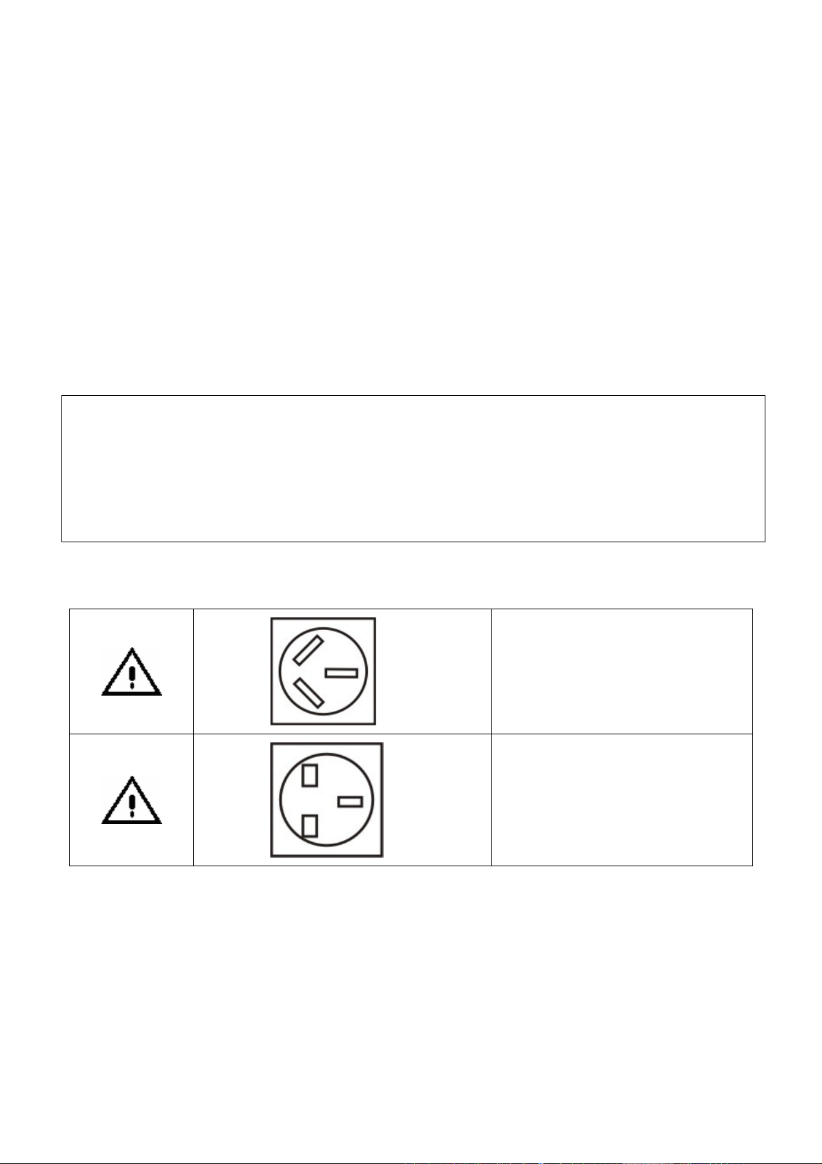
NOTES ON POWER PLUGS
•
The diagrams above are strictly for illustration purposes only.
•
Only one power plug is included in the receiver’s accessory box (page 58) .
This power plug is used in Australia
only
This power plug is used in some other
regions
3
Page 4

NOTES ON COPYRIGHT
•
It is forbidden by law to cop y, bro adcast, show, broadcast on cab le and play in public copyrighted m aterial
without permission.
NOTES ON HANDLING
•
This unit is susceptible to surround ing environmental changes such as s hock, vibration and temperature.
1. Do not apply shock or vibration to the unit.
2. Do not use the unit on a shaky or unstable place.
3. Do not install the u nit on a non-flat surface.
4. Do not cover up the ventilation holes of the unit.
5. Do not use the unit i n a high temperature environment or environment with extrem e changes in
temperature.
6. Never remove the top cover, disassemble or m odify the unit. Moreover, removing the top co ver voids the
warranty even if the product is within th e warranty period.
•
When moving the unit to a remote location, cover the unit with a piece of cloth to prevent injur y. Also, tak e
care not to shake or apply shock to the unit.
•
The top cover or rear panel m ay become warm after operating for a lon g time. This is not a malfunction.
•
Do not use insec ticide sprays, etc., near the unit. Also, do not leave rubber or plastic objects in contact with
the unit for long periods of tim e. This may cause discoloring of this unit’s f inish.
•
Keep the original packing that this u nit came in and use it to re-pack the unit when moving or transporting.
ABOUT CLEANING
•
Do not use solvents such as benzene, alcohol or thinner to clean the unit. These solvents ma y distort the
chassis or dam age its finish. If r ubber or vinyl products remain in contact with the unit for a long time, a st ain
may result.
•
When the unit becomes dirty, clean it gently with a piece of soft, dry cloth.
•
When the unit is very d irty, remove the power plug f rom the wall s ocket and use a piece of damp cloth to
wipe the unit clean. Finish the clean ing with a piece of dry cloth.
DISCLAIMER
This manual has been validated and revie wed f or accuracy. The instructions and descr iptions it contains are
accurate f or the HD-C26H receiver at the time of this manual’s production. However, succeeding units and
manuals are subject to change without notice. Toshiba assumes no liabilit y f or damages incurred directl y or
indirectly from errors, om issions or discrepancies between the receiver an d the manual.
4
Page 5

Exemptions
We hope that you are completely sa tisfied with your Toshiba Digital HD Receiver and it will give you long and
e. We look forward to providing you with additional Toshiba products to s erve all of your
Toshiba is not liable for any dam age caused by fire, natura l disaster (such as thunder, earthquak e, etc.)
acts by third parties, accidents, m isuse, or uses in other improper condit ions.
Toshiba is not liable for incidental dam ages (s uch as profit loss or interruption in business, etc.) caused b y
use or inability to use of this pr oduct.
Toshiba is not liable for any damage caused b y neglect of the instructions described in the owner’s manual.
Toshiba is not liable for a ny damage caused by misuse or malfunction through simultaneous use of this
product and the connected equipm ent.
Thank you very much for purc hasing this Toshiba Digital HD Rece iver HD-C26H.
In order to enjoy the many features this receiver has to off er, read this owner’s manual thoroughl y before using.
enjoyable servic
entertainment needs in the f uture.
In the space provided below, rec ord the Serial Number located on th e rear panel of your receiver.
Model No. HD-C26H Serial No.
Retain this information for future ref erence.
5
Page 6

6
Page 7

TABLE OF CONTENTS
PRECAUTIONS...... ....................................... ..................................... ........................................ ........................................ ....... 2
CHAPTER ONE...... ....................................... ..................................... ........................................ ........................................ ....... 9
INTRODUCTION ........................ ....................................... ........................................ .................................... ............................ 9
INTRODUCTION ........................ ....................................... ........................................ .................................... .......................... 10
IDENTIFICATION
FRONT PANEL .............................. ........................................ ........................................ ........................................ ........ 11
REAR PANEL .................................... ....................................... ......................................... ....................................... ..... 12
REMOTE CONTROL ................................................... .................................... ........................................ ...................... 13
CHAPTER TWO ......................... ....................................... ........................................ ..................................... ......................... 15
STARTUP GUIDANCE ....... ....................................... .................................... ........................................ .................................. 15
INSTALLING
STEP A: CONNECTIONS ...... ....................................... .................................... ........................................ ..................... 16
1 CONNECTING TO TV... ....................................... .................................... ........................................ ...................... 16
2 CONNECTING TO AMPLIFIER ...................................... .................................... ........................................ ........... 21
3 CONNECTING TO MAINS SUPPLY .................. ...................................... ........................................ ...................... 21
STEP B: PREPARING YOUR REMOTE CONTROL ................................................. ........................................ ............ 22
STEP C: SETTING UP YOUR RECEIVER ............ ...................................... ........................................ .......................... 24
VIEWING PROGRAMS............................ ........................................ ........................................ .................................... ....... 26
TURNING
CHAPTER THREE ................................................... ..................................... ........................................ .................................. 27
FUNCTIONS........... ....................................... .................................... ........................................ ........................................ ...... 27
MENU ........................ ........................................ ........................................ .................................... ..................................... 28
MENU MAP ............................ ........................................ ........................................ .................................... .................... 28
OF
CONTROLS .............. ....................................... ..................................... ........................................ ... 11
THE RECEIVER .................. ........................................ ........................................ .................................... ...... 16
OFF THE RECEIVER...................... ....................................... ........................................ .................................... 26
MAIN MENU............... ....................................... .................................... ........................................ ................................. 29
INSTALLATION.......... ....................................... ..................................... ........................................ ................................ 29
QUICK SCAN (For Australia Only) ................................. ..................................... ........................................ .............. 30
AUTO SCAN (For Australia Only) ...................................... ........................................ .................................... ........... 30
MANUAL SETUP ...................................... ....................................... ........................................ ................................. 31
RESET DATA ................................ ........................................ ........................................ ........................................ .... 31
S/W UPDATE ........ ........................................ .................................... ........................................ ................................ 32
PROGRAM................. ....................................... ..................................... ........................................ ................................ 34
PROGRAM LIST ........... ........................................ .................................... ........................................ ........................ 34
EPG (Electronic Program Guide) ........................................ ........................................ .................................... .......... 34
SYSTEM ............................................ ....................................... ......................................... ........................................ .... 35
VIDEO SETUP .............. ........................................ .................................... ........................................ ........................ 35
AUDIO SETUP ...... ........................................ .................................... ........................................ ................................ 36
PASSWORD ................................................ .................................... ........................................ ................................. 36
TIME SETUP ................................. ........................................ ........................................ ........................................ .... 37
EXT CONTROL ............................. ....................................... ........................................ ........................................ ..... 37
EDIT CHANNEL ..................... ....................................... ........................................ ..................................... .................... 38
FAVORITE&LOCK ......... ....................................... .................................... ........................................ ........................ 38
PARENTAL RATE (For Australia Only) .................. ..................................... ........................................ ...................... 3 9
VIRTUAL KEYBOARD ... ....................................... .................................... ........................................ ........................ 39
PROFILE ................................. ....................................... ........................................ ........................................ ................ 40
I-PLATE SETUP ............................ ........................................ ........................................ ........................................ .... 40
FP DISPLAY SETUP......... ....................................... ..................................... ........................................ .................... 41
7
Page 8

INFORMATION .............................. ....................................... ........................................ ........................................ .... 41
QUICK
CHAPTER FOUR ................. ....................................... ........................................ .................................... ................................ 49
APPENDICES ..................................................... .................................... ........................................ ........................................ 49
1
2
3
4
5
6
CONTROL ........ ........................................ .................................... ........................................ .................................. 42
INFO (I-Plate) ......................... ....................................... ......................................... ........................................ ........... 42
TV/RADIO (PROGRAM LIST) ........................ ....................................... ........................................ ............................ 43
EPG (Electronic Program Guide) ..... ..................................... ........................................ .................................... ........ 43
FAV. (Favorite Channel List) .... ..................................... ........................................ ..................................... ............... 44
PIP (Picture-in-Picture)....................... ...................................... ........................................ ........................................ . 44
TTX (Teletext) ......... ....................................... .................................... ........................................ ............................... 45
CC (Closed Caption) (For Australia Only) ............... ..................................... ........................................ ..................... 45
V.FORMAT (Video Format) .............................. ..................................... ........................................ ............................ 45
A.RATIO (ASPECT RATIO) ........... ....................................... ........................................ ..................................... ....... 46
SLEEP......................... ....................................... ........................................ ..................................... .......................... 46
AUDIO ..................................... ....................................... ........................................ ........................................ ........... 47
RECALL .................. ........................................ .................................... ........................................ .............................. 47
AUSTRALIAN DTV CHANNEL TABLE ................. ........................................ .................................... ............................. 50
TROUBLESHOOTING .. ....................................... ..................................... ........................................ ............................. 53
PARENTAL GUIDANCE CODES ............................. ....................................... ........................................ ...................... 55
GLOSSARY....................... ........................................ ........................................ .................................... ......................... 56
TECHNICAL SPECIFICATIONS ................................... ........................................ ........................................ ................. 58
INSTRUCTION GUIDE FOR PROGRAMMING REMOTE CONTROL ............................... ........................................ .... 60
8
Page 9

Chapter One
INTRODUCTION
Introduction 10
Identification of Controls
1
Front Panel 11
2
Rear Panel 12
3
Remote Control 13
9
Page 10

INTRODUCTION
Toshiba HD-C26H Digital High Definition Receiver opens up to a new world of free-to-air terrestrial HDTV (Hig h
Definition Television) and SDTV (Standard Definition Television) programs. The receiver can receive channels
from both VHF and UHF bands. All the major terrestrial free-to-air station numbers currently available in your
area are listed in the on-screen menu. To watch a channel, simply select the channel number and you will be
accessing a wide range of high quality digital programs.
The receiver is fully MPEG 2 / DVB-T compliant, delivering high definition crystal-sharp video and Dolby® Digital
sound. As it supports a channel frequency range of 51-858MHz, it can be easily programmed for all the channels
within the VHF and UHF frequency bands. To find out the channel frequencies in your area, please contact your
local service provider.
FEATURES
X HD 1080i/720p/576p Capability
High Definition (HD) brings a wide-screen format to the home television as well as a sharper picture. This unit
accepts all DTV formats, including 1080i, 720p and 576p.
X HDMI™
Toshiba HD-C26H incorporates the High-Definition Multimedia Interface (HDMI) technology to provide the best
video and audio quality over a single cable.
X WEEKLY EPG
Programs for the whole week are available in the EPG provided the broadcasters broadcast these data.
X Video Format Auto-Switch
The HD-C26H receiver has the capability of automatically switching the output video format to match the native
video format coming from the broadcaster. This reduces possible distortion due to up/down conversions.
X Dolby® Digital
Dolby® Digital is the surround sound technology used in theatres showing the latest movies, and is now
available to reproduce this realistic effect in the home. You can enjoy motion pictures and live concert TV
programs with this dynamic realistic sound by connecting HD-C26H to a 6-channel amplifier equipped with a
Dolby® Digital decoder.
X PIP (Picture-in-Picture)
This feature gives you the ability to view 2 different live channels (from the same frequency) at the same time.
The PIP window can be moved to any corner of the screen or be formed as a double window.
X Teletext/Fastext
Fastext is a method of viewing Teletext pages by related subjects grouped by the broadcast studio. You can
access any given topic shown on the screen simply by pressing the corresponding colored text select button on
the remote control. Note that the Fastext feature is not available in Australia.
____________________
1
HDMI, the HDMI logo and High-Definition Multimedia Interface are trademarks or registered trademarks of HDMI
Licensing LLC.
2
Manufactured under licence from Dolby Laboratories. Dolby and the double-D symbol are registered trademarks of Dolby
Laboratories.
1
2
10
Page 11
INTRODUCTI
ON
IDENTIFICATION OF CONTROLS
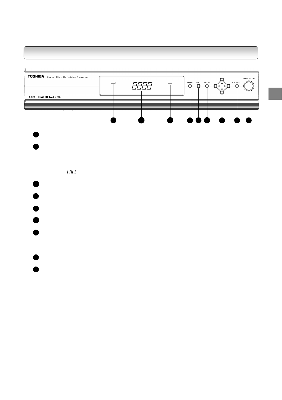
FRONT PANEL
2
1
RED LED INDICATOR
ON: Receiver in standby mode
2
FOUR-DIGIT LED DISPLAY
- Shows current time or off in standby mode
- Shows current time or channel number in power-on mode
- Shows “8888” when time information is not available
- Shows “ ” when receiver is switching from standby to power-on mode
- Momentarily shows the new video format when changing the video format setting
3
ORANGE LED INDICATOR
ON: Signal captured; OFF: No signal received
4
MENU BUTTON
Activate the On Screen Display Menu
5
EXIT BUTTON
Exits from the Main Menu or returns to the Main Menu from submenu
6
ENTER BUTTON
Select the highlighted menu or submenu item
7
DIRECTIONAL BUTTONS
- Move the selection focus on the screen
- Left and right buttons for increasing and decreasing audio volume
- Up and down buttons for channel up and down functions
8
V.FORMAT BUTTON
Toggles among “AUTO”, “1080i”, “720p”, “576p” and “576i” video output formats
9
STANDBY/ON BUTTON
Toggles the receiver between power-on and standby modes
4
5
3
6
7
8
91
11
Page 12
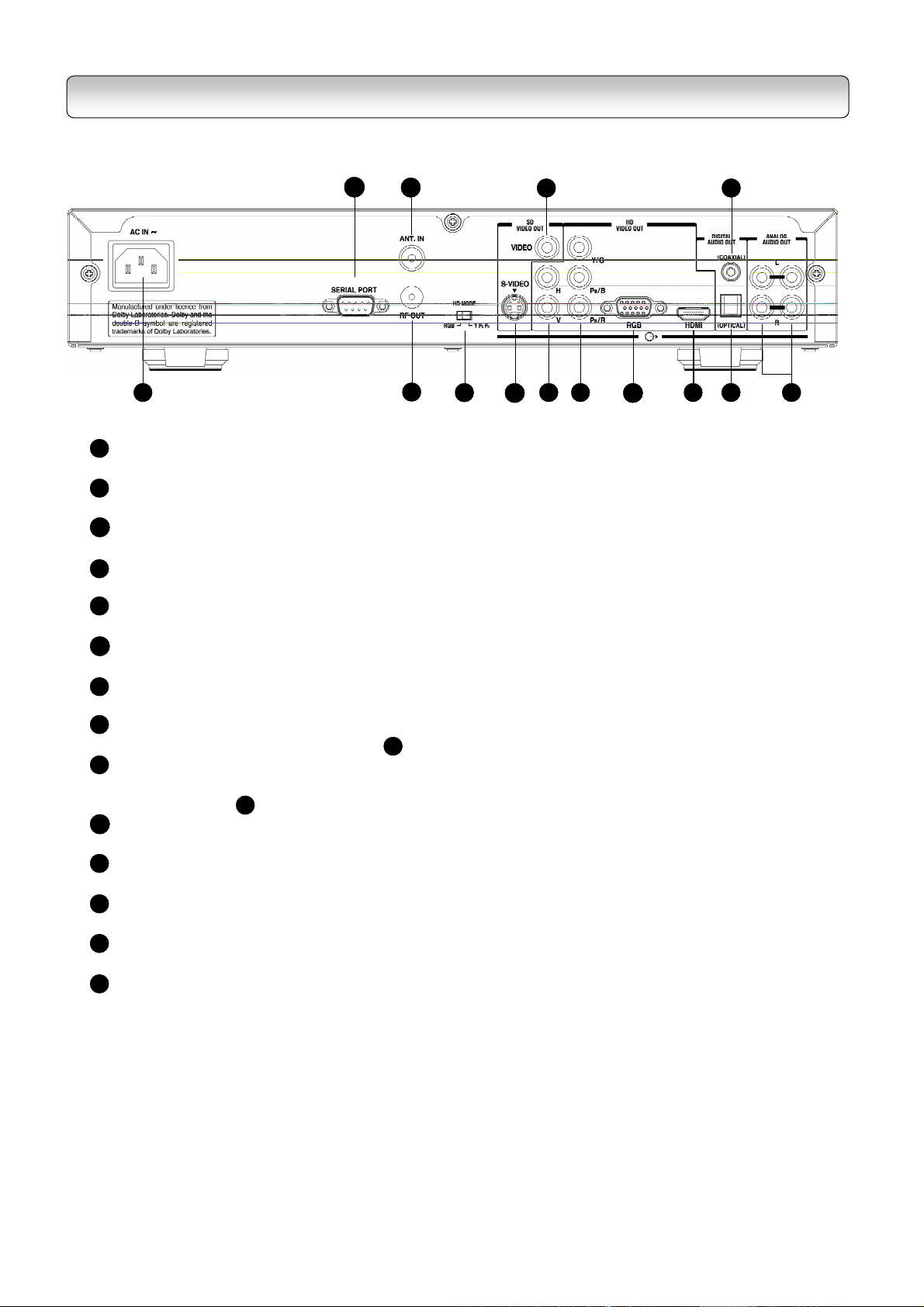
REAR PANEL
1
AC MAINS SUPPLY
1
2
3
4
5
7
8
6
9
10
11
100~240 VAC, 50/60 Hz
SERIAL PORT
2
For connection to PC for software upgrade or to other external devices for external control
ANT.IN
3
For connection to UHF/VHF antenna
RF OUT
4
For connection to analogue TV’s antenna input
5
HD MODE-SWITCH
To switch HD output mode between RGB and YPBPR
S-VIDEO OUT
6
For connection to TV’s S-Video input
COMPOSITE VIDEO OUT
7
For connection to TV’s composite video input
8
H,V OUT
Used together with RGB OUT(Label ), for connection to TV’s RGBHV inputs
9
YPBPR/RGB OUT
9
For connection to TV’s YPBPR(component video) or RGB inputs, selectable via the MODE-
SWITCH (Label )
10
RGB (Mini D-Sub 15-pin) OUT
5
For connection to TV’s Mini D-Sub 15-pin input
11
HDMI OUT
For connection to TV’s HDMI input
12
DIGITAL AUDIO (OPTICAL) OUT
For optical connection to an amplifier equipped with a Dolby® Digital decoder
13
DIGITAL AUDIO (COAXIAL) OUT
For coaxial connection to an amplifier equipped with a Dolby® Digital decoder
14
ANALOG AUDIO L/R OUT
For connection to TV’s Audio L/R Audio inputs
13
12
14
12
Page 13
INTRODUCTI
ON
REMOTE CONTROL
16
1
2
3
17
18
19
4
5
6
7
20
21
22
23
8
9
10
11
12
13
14
15
24
25
26
27
28
29
30
31
13
Page 14

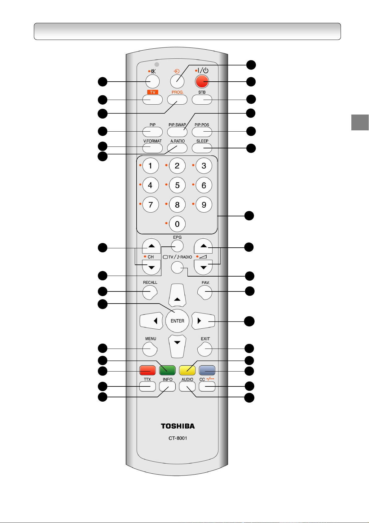
REMOTE CONTROL
MUTE button
1
TV FUNCTION button*
2
PROG. Button Page 60
3
PIP button
4
VIDEO FORMAT button
5
ASPECT RATIO button
6
CHANNEL UP/DOWN buttons
7
EPG button
8
RECALL button
9
Page 26
Page 44
Page 43
Page 47
Page 45
Page 46
Page 26
17
18
19
20
21
22
23
24
25
STANDBY/ON button
SET TOP BOX button**
PIP SWAP button
PIP POS. button
SLEEP button
CHANNEL NUMBER button
VOLUME UP/DOWN buttons
TV/RADIO button
FAV. button
Page 46
Page 44
Page 24
Page 44
Page 44
Page 43
Page 26
Page 26
ENTER button
10
MENU button
11
GREEN button
12
RED button
13
TTX button
14
INFO button
15
INPUT SELECT button
16
* TV FUNCTION – Set the Rem ote Control Unit to function with the T elevision Set. See RCU
programming guide on page 60
** SET TOP BOX– Set the Rem ote Control Unit to function with the Set Top Box.
Page 29
Page 45
Page 42
Page 60
.
26
28
30
31
DIRECTIONAL buttons
EXIT button
27
YELLOW button
BLUE button
29
CC/DIGIT SELECTION button
AUDIO button
Page 47
Page 60
14
Page 15

Chapter Two
STARTUP GUIDANCE
Read this chapter first to make all necessary preparations.
1
Installing the Receiver 16
- Connections 16
- Preparing your remote control 22
- Setting up your receiver 24
2
Viewing programs 26
3
Turning off the receiver 26
15
Page 16
INSTALLING THE RECEIVER
Follow steps A to C below. Your receiver will be ready to display digital programs on your TV.
STEP A: CONNECTIONS
DO NOT PLUG THE RECEIVER INTO THE MAINS YET.
Before you use this receiver, it is necessary to connect it to your TV.
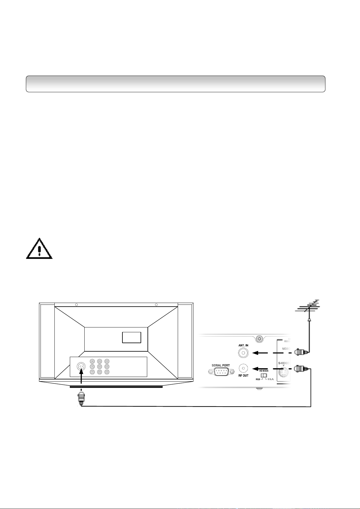
1
CONNECTING TO TV
1-1.
Disconnect the antenna cable from your TV and connect it to the “ANT. IN” terminal on the back of the
receiver.
1-2.
This “RF OUT” provides you a RF loop-through function to receive analogue TV programs as well as digital
programs. Use an RF coaxial cable (not supplied) to connect the HD-C26H “RF OUT” terminal to TV’s or VCR’s
antenna input.
Connection to Antenna
“RF OUT” Connection to TV or VCR
Before connecting or disconnecting the antenna cable, unplug the receiver, VCR, TV and
antenna booster, if any.
TV
Antenna Cable
(Not Supplied)
HD-C26H
To TV antenna input
RF coaxial cable
(not supplied)
16
Page 17
STARTUP GUIDANCE
1-3.
In the accessory box, you will find two sets of cables: One is the component video cable (with red, green and
blue connectors) and the other is the Audio/Video cable (with yellow, white and red connectors).
For better video quality, it is recommended that you use the HDMI cable, the Mini D-Sub 15-pin cable or the
RGBHV video cable (with 5 RCA connectors). These cables are not included in the HD-C26H package.
HD MODE Switch selection is essential for several outputs. Refer to the HD MODE Switch table on page 54 for
making the correct switch selection according to your output connection.
You have 6 choices for connecting the video output from the receiver to your TV. Use only one of the following
connections (with (a), (b) or (c) being the best choice):
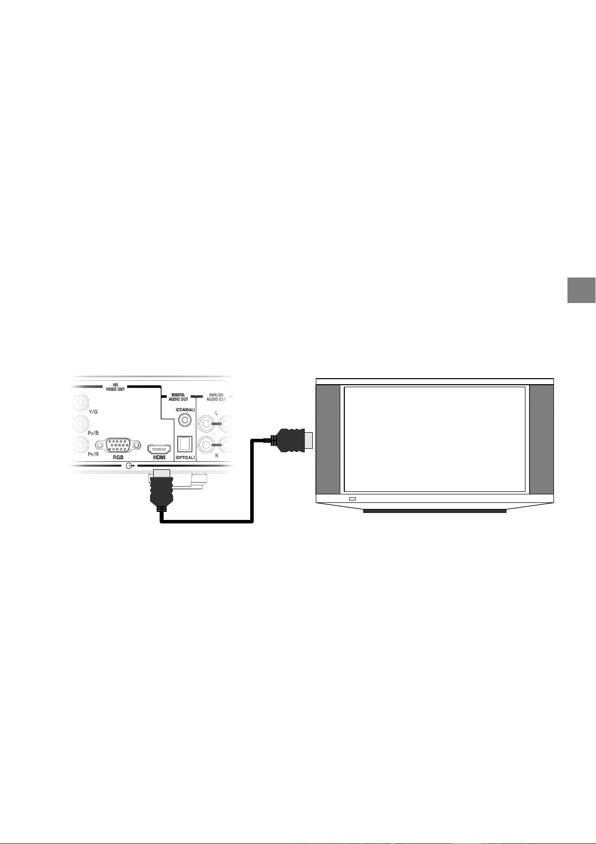
Connections to TV – Video Connection
(a) HDMI connection: If your TV has HDMI input, use a HDMI cable (not supplied) to connect the
receiver to your TV. HDMI supports video and multi-channel audio in a single cable; therefore
separate connection for audio is not necessary.
HD-C26H TV
To TV HDMI input
HDMI cable
(not supplied)
Note: Because HDMI is an evolving technology, it is possible that some TVs may not operate properly
with the receiver.
(b) Mini D-Sub 15-pin connection: If your TV has a RGB Mini D-Sub 15-pin video input connector, use a
Mini D-Sub 15-pin cable (not supplied) to connect the receiver to your TV. Set the HD MODE Switch
(refer to page 54) to RGB, and then connect the RGB connector on the rear of the receiver to the
corresponding socket on the TV.
Do not connect any PC monitor to the receiver via Mini D-Sub 15-pin cable.
17
Page 18
HD-C26H
TV
To TV Mini D-sub 15-pin
video input
RGB
HD MODE
YPBP
R
Mini D-sub 15-pin video cable
(not supplied)
Note: This diagram illustrates video connections only. Refer to Page 20 for Audio connection.
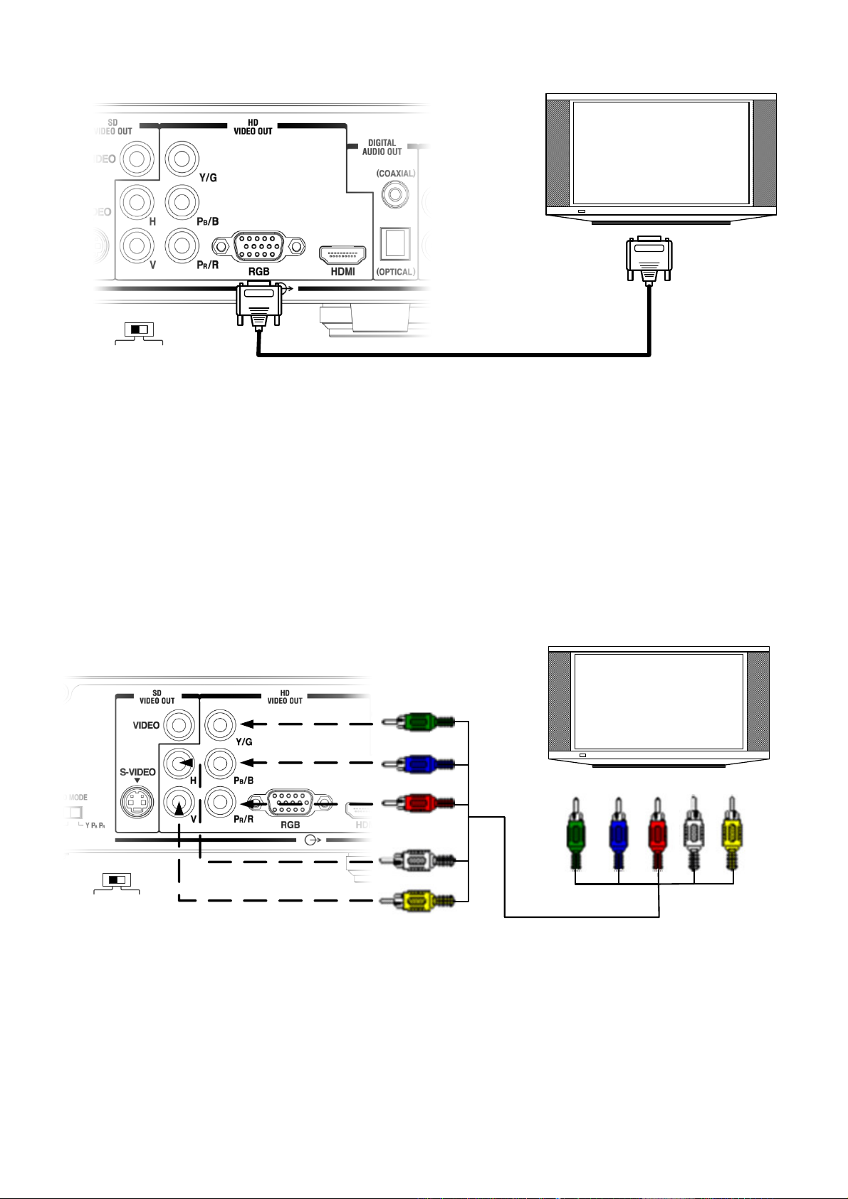
(c) RGBHV (RCA) connection: If your TV has RGBHV video inputs, use a RGBHV video cable (not
supplied) to connect the receiver to your TV. Set the HD MODE Switch (refer to page 54) to RGB, and
then connect the Y/G, PB /B, PR/R, H and V connectors from “HD VIDEO OUT” on the rear of the
receiver to the corresponding jacks on the TV.
TV
To TV RGBHV
Video inputs
R
B
H V
HD MODE
YPBP
RRGB
HD-C26H
Match the colors
when connecting
G
B
R
H
V
G
RGBHV video cable
(not supplied)
Note: This diagram illustrates video connections only. Refer to Page 20 for Audio connection.
18
Page 19
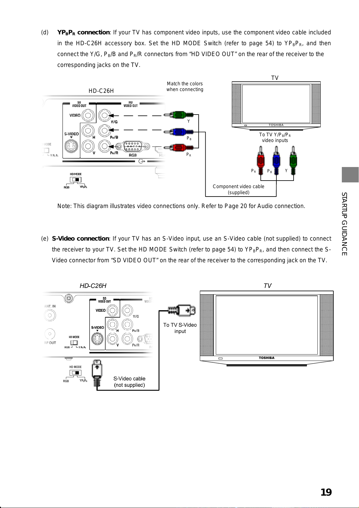
(d) YPBPR connection: If your TV has component video inputs, use the component video cable included
in the HD-C26H accessory box. Set the HD MODE Switch (refer to page 54) to YP
connect the Y/G, P
/B and PR/R connectors from “HD VIDEO OUT” on the rear of the receiver to the
B
, and then
BPR
corresponding jacks on the TV.
TV
Match the colors
when connecting
Y
P
B
P
R
To TV Y/PB/P
P
R
Component video cable
(supplied)
TOSHIBA
video inputs
P
B
R
Y
RGB
HD MODE
HD-C26H
YP
BPR
Note: This diagram illustrates video connections only. Refer to Page 20 for Audio connection.
STARTUP GUIDANCE
(e) S-Video connection: If your TV has an S-Video input, use an S-Video cable (not supplied) to connect
the receiver to your TV. Set the HD MODE Switch (refer to page 54) to YP
, and then connect the S-
BPR
Video connector from “SD VIDEO OUT” on the rear of the receiver to the corresponding jack on the TV.
Note: This diagram illustrates video connections only. Refer to Page 20 for Audio connection.
19
Page 20
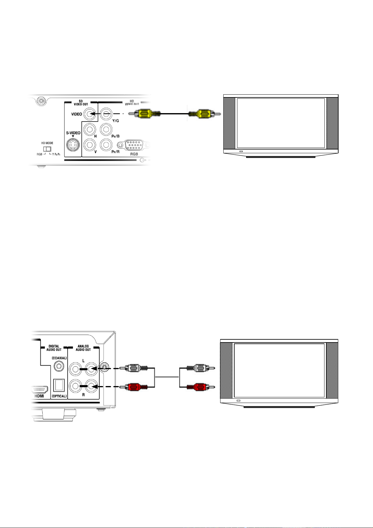
(f) Composite video connection: If your TV has composite video inputs, use the yellow connector of the
Audio/Video cable included in the HD-C26H accessory box. Connect the yellow video connector from
“SD VIDEO OUT” on the rear of the receiver to the corresponding jack on the TV.
HD-C26H
To TV
composite
video input
Audio/Video cable
(supplied)
TV
Note: This diagram illustrates video connections only. Refer to Audio connection below.
1-4.
Connections to TV – Audio Connection
For audio connections, you have two choices. You can connect the receiver to your TV or to an audio amplifier
equipped with a Dolby® Digital decoder. If you do not have an external amplifier equipped with a Dolby® Digital
decoder, use the red and white connectors of the Audio/Video cable included in the package. Connect the audio
connectors from “ANALOG AUDIO OUT” on the rear of the receiver to the corresponding jacks on the TV: red to
red (right audio) and white to white (left audio).
Note: If your TV has only one audio input jack, connect either the right or left audio connector to the audio jack.
Do not connect the yellow connector to TV if using HDMI, RGB, component video or S-Video connector.
HD-C26H
Match the colors
when connecting
white
red
Audio/Video cable
(supplied)
To TV audio
inputs
white
red
TV
20
Page 21
STARTUP GUIDANCE
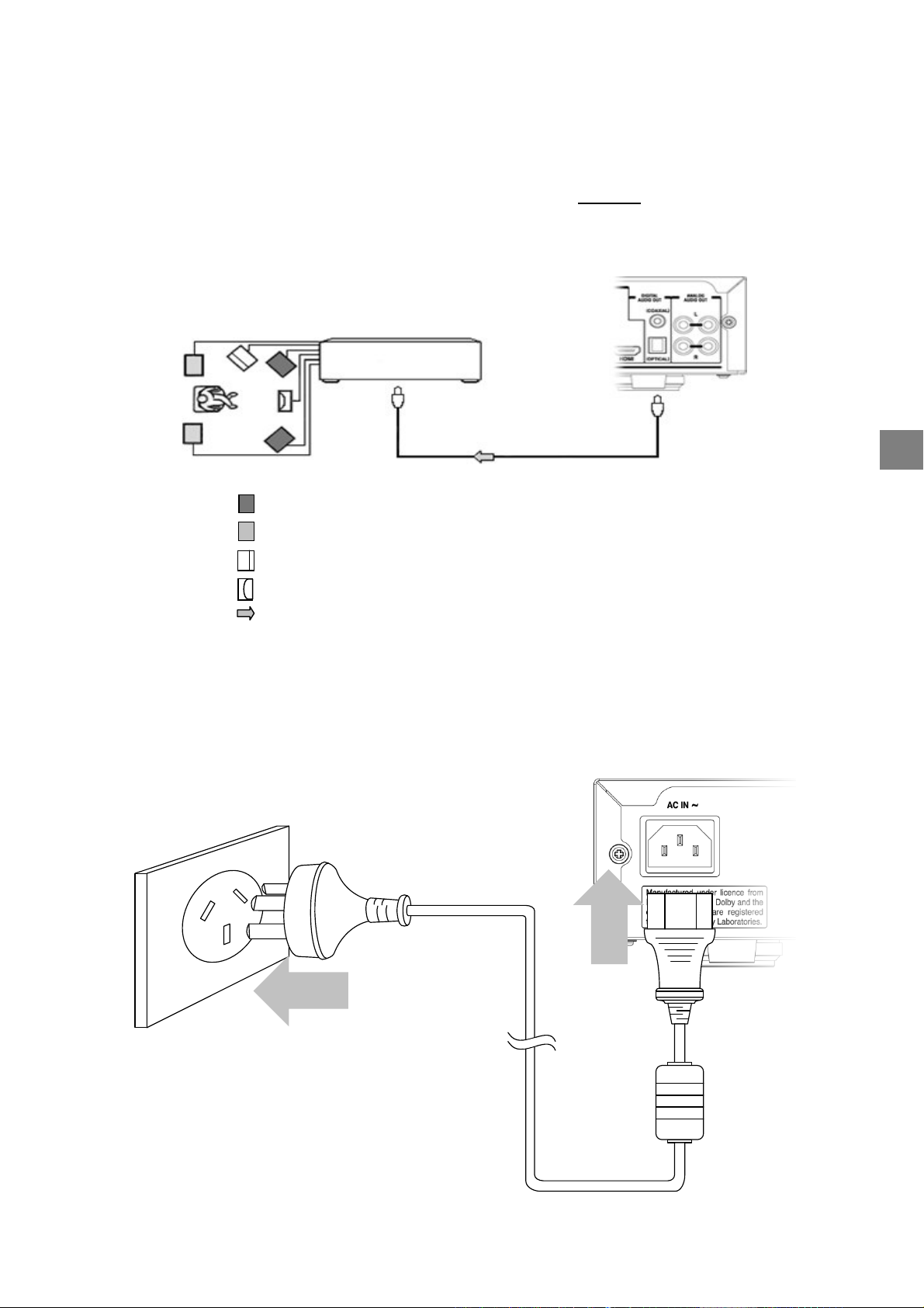
2
CONNECTING TO AMPLIFIER
If you connect this receiver to an audio amplifier equipped with a Dolby® Digital decoder, use an optical or
coaxial digital cable (not supplied) to connect from the receiver’s “DIGITAL AUDIO OUT (Optical/Coaxial)” to the
digital audio input of your amplifier. In this case make sure that you DO NOT need to connect the audio
connectors (red and white) on the Audio/Video cable to your TV.
HD-C26H
Amplifier equipped with
a Dolby decoder
TO DIGITAL AUDIO
(OPTICAL or COAXIAL)
Optical or Coaxial digital cable (not supplied)
: Front speaker
: Rear speaker
Subwoofer
: Centre speaker
: Signal flow
3
CONNECTING TO MAINS SUPPLY
Plug the receiver into the mains.
t
e
l
t
u
O
l
l
a
W
HD-C26H
This diagram is illustrated with an
Australian power plug. In other regions,
please use the appropriate power plug.
Power Cord
(supplied)
21
Page 22
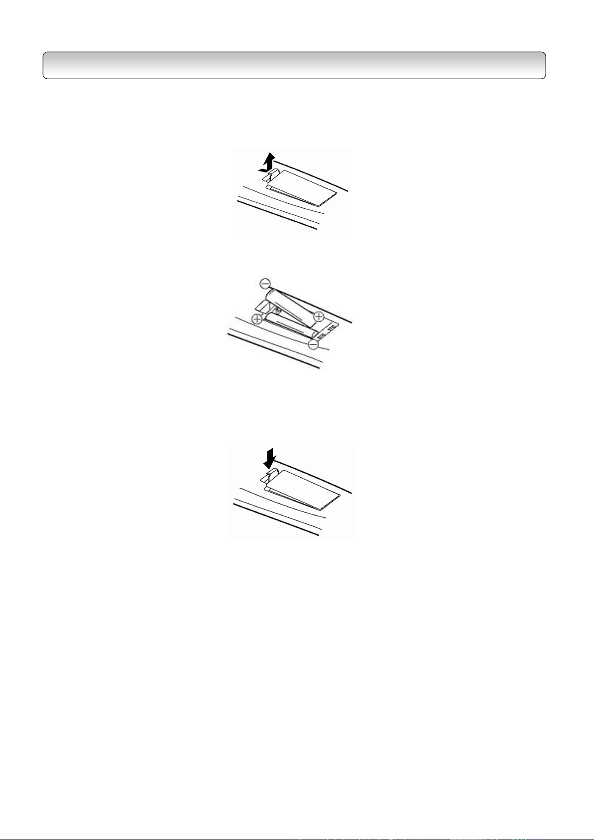
STEP B: PREPARING YOUR REMOTE CONTROL
Loading batteries
1
. Open the Cover.
2
. Insert two R03 (AAA size) batt eries.
- Make sure to match the + and – signs on the batteries to the marks inside the battery compartment.
3
. Close the cover.
Notes on batteries
Improper use of batteries m ay cause batter y l eakage and corrosion. To operate the remote control corr ectly,
follow the instructions below.
Do not insert batteries into t he remote control in the wrong direction.
Do not charge, heat, open, or short-circuit the batteries. Do n ot throw batteries into fire.
Batteries contain toxic substances. Do not dispose of them with ordinary trash. Dispose of batteries only
in accordance with local ordinances.
Do not leave dead or exh austed batteries in the remote c ontrol.
Do not use different t ypes of batteries together, or mix old and ne w batteries.
If you do not use the remote control for a lo ng period of tim e, remove the batteries to avoid possible
damage from battery corrosion.
If the remote control does not function correc tly or if the operating range becom es reduced, replace all
batteries with new ones.
22
Page 23

STARTUP GUIDANCE
te control at the remote sensor and press
If battery leakage occurs , wipe the battery liquid from the batter y compartment, then insert new batteri es.
Operating with the remote control
1.
Point th e remo
the buttons.
O
O
30
30
Within about 5m
2.
Distance: About 5 m from the front of the remote sensor.
3.
Angle: About 30° in each direction of the fr ont of the remote
sensor.
Do not ex pose the rem ote sensor of the receiver t o a strong light source s uch as direct sunlight or o ther
illumination. If you do so, you m ay not be able to operate the receiver via t he remote control.
Do not drop or give the rem ote control a shock.
Do not leave the rem ote control near an extremely hot or hum id place.
Do not spill water or put an ything wet on the remote control.
Do not disassem ble the remote control.
23
Page 24

Use the directional buttons “◄” and “►” to
of residence and press the
The
setup process m ay tak e a f ew m inutes
Selection” menu does not
to
STEP C: SETTING UP YOUR RECEIVER
Note: If your ser vice pr ovider or antenna installer has already installed your TV system to receive terrestrial TV
programs, do not cha nge any connections of those dev ices or installation setti ngs unless it is absolutely
necessary.
If your serv ice provider or system installer has not conf igured your recei ver, it will not be set up for any
specific c hannel or frequency when powered on for the first time. In this case you s hould follow the steps
below to set up your receiver.
1.
Switch on the TV.
2.
Using your TV’s rem ote control, select t he appropriate external Au dio/Video input on your TV according t o
the connection you have made in Ste p A.
3.
Mak e sure the receiver is alread y in power-on m ode (Left RED LED on front panel is off). If it is in stan dby
mode (Left RED LED in red colour), switch on the receiver by pressing the “ STANDBY/ON” button on the front
panel of the receiver or on the rem ote control.
4.
A m essage “Dat abase is Empty” should appear after a while. If you can see the m essage, g o to St ep 5
directly. However, if you cannot see the m essage on the screen even after a long time, change the video form at
by pressing V.FORM AT button on rem ote control or on th e front panel. Press V.FORMAT button until you s ee
the message “Database is Em pty”.
Note: When you press V.FORMAT button, the Video Format Indicator on the r eceiver’s front panel w ill display
among “576i” (for HD MODE Switch being set to YP
press V.FORMAT button, m ake sure the front panel display has chan ged before you press the button aga in.
5.
After you see a m essage “Database is Empty” appears , press the “MEN U” button. A “Regio n Selection”
menu appears.
−
only), “AUTO”, “1080i”, “720p” and “576p”. After you
BPR
highlight your region
“ENTER” button to make your selection.
region
to complete.
− If the “Region
appear, refer to “RESET DATA” on page 31
reset the database.
24
Page 25

STARTUP GUIDANCE
6.
You will s ee the Main Menu (page 29). Press the “▼” button twice to highlight “INSTALLATION” and then
press “ENTER”. When prom pted, enter “0000” which is the default password.
7.
To tune the receiver, you have choices of MANUAL SETUP / AUTO SCAN / Q UICK SCAN. W e recommend
that you use “QUICK SCA N” (page 30) for a faster setup. For more information on t he various tuning options,
refer to pages 30~31.
Note: The choices of AUTO SCAN a nd QUICK SCAN are for Australia only.
8.
If you use “QUICK SCAN” in step 7 a nd when you see the m essage “>>> SCAN CO MPLETE <<<”, press
the “EXIT” button several tim es until the main menu disappears.
9.
After you f inish scanning, you can choose the suitable V.F ORMAT. If you use an SDT V, use the V.F ORMAT
“576i”; If you use a HD-ready TV, you ar e rec ommended to change to “AUTO ” by pressing V.FORMAT button;
However, if your HD-read y TV cannot display s ome specif ic video f ormat, press V.FORMAT button to c hange to
an appropriate fixed form at.
10.
Congratulations! You have succ essfully setup your receiver.
25
Page 26

VIEWING PROGRAMS
1
. After you have tuned the receiver, you have several ways to navigate thr ough all programs:
−
Press the “CHANNEL NUMBER” or “CHANNEL UP/DOWN” buttons to s elect a program of your interest.
−
Press the “TV/RADIO” button to call up the “Program List” (page 43) and select a program of your
interest. This will also set your vie wing mode to “Normal”.
−
Press the “FAV.” button to call up the “Favorite C hannel List” and select a program of your interest (page
44). Entries in this “Favorite Channel List” are those that you have added unde r “ FAVORITE&LOCK”
(page 38). This will set your vie wing mode to “Favorite”.
−
Use the “CHANNEL UP/DOWN” buttons to view the previous and next program. T he program s are
arranged according to th e “Program list” or “ Favorite Channel List” (depe nding on your current viewing
mode). See “I-PLATE (INFO) ” on page 42 for more information on vie wing modes.
2
. Press the “INFO” button to view de tails on a program.
3
. Press the “EPG” button to view the Electronic Program Guide on a week ly basis.
4
. Press the “VOLUM E UP/DOW N” buttons to increase or decrease the audio volume, or press the “MUTE”
button to turn off the audio output.
5
. The information conta ined in this chapter (“ST ARTUP GUIDANCE”) is on ly m eant to be a quick installation
guide. Familiarize yourself with oth er functions of the receiver b y reading the remaining chapters in this m anual.
TURNING OFF THE RECEIVER
Set the receiver to standby mode b y pressing the “STANDBY/ON” button.
If you would not us e the receiver for a long tim e, unplug the power cord from the wall outlet to completely
eliminate all voltages.
26
Page 27

Chapter Three
FUNCTIONS
1
Menu
Menu Map 28
Main Menu 29
Installation 29
− Quick Scan 30
− Auto Scan 30
− Manual Setup 31
− Reset Data 31
− S/W Update 32
Program 34
− Program List 34
− EPG 34
System 35
− Video Setup 35
− Audio Setup 36
− Password 36
− Time Setup 37
− Ext Control 37
Edit channel 38
− Favorite&Lock 38
− Parental Rate 39
− Virtual Keyboard 39
Profile 40
− I-Plate Setup 40
− FP Display Setup 41
− Information 41
2
Quick Control
Info 42
TV/Radio 43
EPG 43
Fav 44
PIP 44
TTX 45
CC 45
V.Format 45
A.Ratio 46
Sleep 46
Audio 47
Recall 47
27
Page 28

MENU
MENU MAP
Use the directional buttons to navigate through th e menu, “ENTER” button to choose s pecific items, and “EXIT”
button to return to the main m enu from sub-menu or to leave the m ain menu.
MA IN M EN U
page 29
PR OG RAM
page 34
ED IT C HA NN EL
page 38
FAV OR ITE &L OC K
page 38
PA REN TA L R AT E
page 39
PR OG RAM L IST
page 34
EP G
page 34
INS TA LLA TIO N
page 29
SY ST EM
page 35
PR OFI LE
page 40
I-PL AT E S ET UP
page 40
FP DIS PL AY SE TU P
page 41
INF OR MA TIO N
page 41
VID EO SE TU P
page 35
AU DIO SE TU P
page 36
PA SS WO RD
page 36
TIM E S ET UP
page 37
EX T C ON TRO L
page 37
QU ICK SC AN
page 30
AU TO SC AN
page 30
MA NU AL SE TUP
page 31
RE SET DA TA
page 31
S/W U PDA TE
page 32
Note: If you lea ve the menu s creen for a long period of time, a permanent af terimage may rem ain on the
TV screen.
28
Page 29

FUNCTIONS
MAIN MENU
There are two ways to enter the Mai n Menu when the receiver is powered o n:
1.
On the remote control, press the “ME NU”
button.
2.
Alternatively, press “MENU” button on the
front panel.
3.
Use th e direc tional buttons to n avigate
through the menu, “ENT ER” button to choos e
specific items, and “EXIT” button to return to
the main menu from submenu or to leave th e
main menu.
4.
Menu(s) left displayed for 15 m inutes will exit
automatically.
INSTALLATION
On the m ain m enu, select “INSTALLATION” and key-in your password to enter t he “IN STALLATION” page. The
default password is 0000. Refer to page 36 to c hange the password.
If you are i n Australia, you have choices of MANUAL SETUP / AUTO SCAN / QUICK SC AN to tune the receiver.
If you stay in other region, use MANUAL SETUP to tune the recei ver.
QUICK SCAN
AUTO SCAN
(for Australia only)
(for Australia only)
MAIN MENU INSTALLATION MANUAL SETUP
RESET DATA
S/W UPDATE
29
Page 30

QUICK SCAN (For Australia Only)
The “QUICK SCAN” feature allows you to scan all predefined digital TV and Radio c hannel signals in Australia.
1.
On the insta llation page, hi ghlight “QUICK
SCAN” and press the “ENTER” button .
2.
Use the “▲” and “▼” buttons to highlight the
city you live in and press the “ENTER” button
to start scanning.
3.
It will scan through respective RF channels
available in your city.
4.
Once a digital TV/Radio ch annel is found, the
channel number and programs names in this
channel will be shown.
5.
When you see the message “>>> SCAN
COMPLETE <<<”, you have completed tuning
your r eceiver. If no channel is found, refer to
“TROUBLESHOOTING” in Appendix 2.
6.
Press the “EXIT” button several times to leave
the Main Menu.
Notes:
1. The frequencies of the “quick scan” channels
are preset in the receiver’s database. In case
that the local TV/Radio station changes the
channel frequency or a new channel comes up,
you ha ve to scan these channels using
“MANUAL SETUP”.
2. Receiver is defaulted to TV mode instead of
Radio mode after QUICK SCAN.
AUTO SCAN (For Australia Only)
The “AUTO SCAN” feature allows you to scan all predefined digital TV and Radio channels in Australia. T he
steps required to automatically program the receiver are outlined as below:
1.
Highlight “AUTO SCAN” and press the
“ENTER” button to start channel search.
2.
The receiver starts scanning from channel 2 to
channel 69. The status bar shows the
progress being made.
3.
Once a digital TV/Radio ch annel is found, the
channel number and progr am name will be
shown.
4.
When you see the message “>>> SCAN
COMPLETE <<<”, you have completed tuning
your r eceiver. If no channel is found, refer to
“TROUBLESHOOTING” in Appendix 2.
5.
Press the “EXIT” button to leave M ain Menu.
30
Notes:
1. Auto scan process m ay take about 18 minutes to
complete.
2. Receiver is defaulted to TV mode instead of Radio
mode after AUTO SCAN.
Page 31

FUNCTIONS
MANUAL SETUP
1.
On the “INSTALLATION” page, highlight “MANUAL
SETUP” and press the “ENT ER” button.
2.
Select chan nel number. Be sure you k now the
channel n umber and its RF f requency. You m ay
refer to Digital T V and Radio c hannel table in
Appendix 1.
3.
Press “▼” button to highlight “F requency”,
“Bandwidth” and “Priority” to make sure the
parameters are correct, then press “▼” button to
highlight “Start Scan” and press the “ENTER”
button to start scanning.
• If scanning is successful, “Start Scan” will change to “Get Channel Succ ess” and signal qua lity will be
shown. At this point you can press “EXIT” to leave “MANU AL SETUP” or continue scanning other channels.
• If scanning is uns uccessful, “Start Scan” will cha nge to “Timeout Error”. At this point you can rescan
the signal or refer to the SIGNAL LEV EL bar and signal QUALITY for aligning t he direction of the
antenna to get the signal. Refer to your antenna installer if problem persists.
Notes:
1. For Australia, the BANDWIDTH should be 7MHz.
2. The PRIORITY should be set to “HIGH” for Australia.
3. SIGNAL LEVEL ref ers to the input RF signa l strength as perce ived by t he receiver. Note t hat too
strong a signal may c ause err oneous readings. If you use an antenna booster and f ind that you s till
get a low signal level, your booster gain may be set too high. In this case, adjust the gain acc ordingly.
You may also see the OSD “Bad or No Signal” or “W eak Signal” when the signal level is low. T his
signal-level indicator is for ref erence only.
QUALITY ref ers to the quality of the received digital signal. A high value of quality m eans that there
are few err ors in the signal. In the sam e way, a low value of quality im plies that ther e are a large
number of errors in the signal, which m ay cause distortions in video and a udio.
SNR is the signal-to-noise ratio. A high SNR value m eans that you have a reasonably good
reception (good signal level and good quality).
RESET DATA
Use this function when you want to c lear channel data and reset the password to def ault (“0000”).
This function is to be used under any one of the following circumstances:
− When the “Region Selection” m enu does not appear on step 5 of page 24;
− When moving to another city.
1.
On the “INSTALLATION” page, highligh t “RESET
DATA” and press the “ENTER” button.
2.
Select “YES” to restore to default data.
3.
The receiver will re boot autom atically. You will see
a message “Database Empty” after the boot up
process. You can then pr oceed to set up your
31
Page 32

S/W UPDATE
This option in the “INSTALLATION” page updates the software in the receiver. By k eeping the system software
up-to-date, you enjo y the latest features and bug f ixes. Howev er, bef ore you proceed to update the software,
consult your local dealer to obtain the latest software and make sure you k now how to operate HyperTerminal®3
for the Windows®4 operating system on your com puter.
1.
Highlight “ S/W UPDATE” and press the “ENTER”
button.
2.
Use the “◄” and “►” buttons to highlight bet ween
“YES” and “NO”.
3.
Before you select “YES”, follow the steps
outlined below to configure your PC first:
(a) Connect PC to your HD- C26H receiver with a
RS232 cable (modem cable).
(b) On the PC side:
- Launch the HyperTerminal® application.
- Name the connectio n.
- Select the correct CO M port – usually COM1.
- Use the following COM port settings:
baud rate: 115200
data: 8
parity: none
stop bit: 1
flow control: none
- After you click the “OK” bu tton, you may see
many messages appearing in the
HyperTerminal screen. Ignore them and
proceed to the next step.
- Select H yperTerminal’s basic f unction
“Transfer”.
- Select “Send File”.
- Browse to select the updated software file.
- Transfer protocol: “1K Xmodem”
DO NOT click on the “Send” button at this
time yet.
4.
Now that your PC has be en properly configured,
you can highlight “YES” on the TV screen a nd
press the “ENTER” button on the rem ote control.
5.
After selecting “YES”, you will see the current
software version on the T V screen. Make sure this
software version is differ ent from the version of the
new software file stored on your PC. Select “YES”
again to proceed with the do wnload.
6.
Now click on the “Send” button on your PC
HyperTerminal to s tart uploading th e new
software.
7.
On the TV screen, you will see the window with a
status bar indicating the download progress.
3
HyperTerminal® is a registered trademark of Hilgraeve Inc.
4
Microsoft® and Windows® are either registered trademarks o r trademarks of Microsoft Corpo ration in the United States
and/or other countries.
Note: It is safe to turn off the receiver only after t he
receiver has bo oted up autom atically. Do not
disconnect the receiver fr om the power source
during th e software update proces s. If there is a
power f ailure during this time, the receiver may
become unusable. In th is case, contact your
local dealer.
32
Page 33

FUNCTIONS
8.
When download is completed, the receiver will
reboot automatically. You can now exit
HyperTerminal.
9.
After the receiver is booted up, you will see a
message window inf orming you that the receiver’s
database is empt y. Note that the password will
also b e reset to the default “0000”. Now press the
“MENU” button and select your region of
residence.
10.
On the Main Menu, select “PROFILE” and then
“INFORMATION” to confirm the current s oftware is
indeed changed to the new one. You can then
proceed to tune your receiver by following
“INSTALLATION” instructions on page 29.
Over tim e, Autom atic Software Upgrade service will be available as broadcas ters trans mit new software of your
receiver. It is recommended to carry out the software upgrade so that the rec eiver is equipped to perform better.
1.
When a new version of software for Toshiba HD-
C26H is found, an OSD appears prom pting for a
software upgrade.
2.
Press the “ENTER” butt on to accept the software
upgrade or the “EXIT” button to ca ncel.
3.
If the software upgrade has been accepted, t he
system will be rebooted. Upon startup ,
downloading of the new sof tware will take place.
Progress is sho wn on the fr ont panel displa y with
an “OTA” and a running line.
4.
The downloading process usuall y takes a short
while and when it has com pleted, the s ystem will
reboot again. Upon the sec ond startup, the system
has completed the upgrading process and the
database will be em pty as default. T hen proceed
with the Installation process. (Refer to page 29)
33
Page 34

T his sets your current viewing mode to
f or
preview a channel an d
PLATE
press the
is
via the “TV/Radio” button on the r emote control.
PROGRAM
MAIN MENU PROGRAM
1.
On the Main Menu, select “PROG RAM”
2.
Use “▲” and “▼” buttons to highl ight the options
- PROGRAM LIST
- EPG
PROGRAM LIST
EPG
PROGRAM LIST
1.
Highlight “PROGRAM LIST ” and press the “ENTER”
button.
“Normal”. See “I- PLATE (INFO)” on page 42
more information.
2.
Use the directional buttons to high light a channel.
3.
Press the “ENTER” but ton to
show “Now & Next info”. Refer to page 42 “I-
(INFO) for details.
4.
To exit from the “PROGRAM LIST”,
“EXIT” button.
Note: An other way to ca ll up the “PROG RAM LI ST”
Refer to “TV/Radio” on page 43 for details.
EPG (Electronic Program Guide)
1.
Highlight the “EPG” and press the “ENTER”
button.
Note: Another way to call up the “EPG” is via the
“EPG” button on the remote control.
Refer to “EPG” on page 43 for details.
34
Page 35

FUNCTIONS
SYSTEM
M A I N M E N U S Y S T E M P A S S W O R D
1.
On the main menu, select “S YSTEM”.
2.
Use the “▲” and “▼” buttons to highlight the
options
- VIDEO SETUP
- AUDIO SETUP
- PASSWORD
- TIME ZONE
- EXT CONTROL
V I D E O S E T U P
A U D I O S E T U P
T IM E S E T U P
E X T C O N T R O L
VIDEO SETUP
1.
Highlight “VIDEO SET UP” and press t he “ENTER”
button.
2.
Use the “▲” and “▼” buttons to highlight the
options
- HD OUTPUT FORMAT
- ASPECT RATIO
HD OUTPUT FORMAT
Use the “◄” and “►” buttons to switch among vide o
formats “576i” (for HD MODE Switch b eing set to
YP
“AUTO” mode, the receiver switches the video o utput
format to the same as sent by the broadcast er
automatically. Otherwise, t he receiver will fix its video
output at the format you have selecte d.
SD OUTPUT FORMAT
This setting cannot be changed.
ASPECT RATIO
Use the “◄” and “►” buttons to s witch among the three
different aspect ratios “4:3 NOR MAL”, “16:9
WIDESCREEN” and “4:3 LETT ERBOX”. Refer to the
table on page 46 for more inform ation.
only), “AUTO”, “1080i”, “720p” an d “576p”. In
BPR
35
Page 36

Notes:
1. Alternatively, you can press the “V.FORMAT” button on the remote control to change the output form at as
described on page 45.
2. You can also press “A.RATIO” button on the remote control to change the aspect ratio as described on
page 46
3. “AUTO - 1080i” means that the receiver is in a uto-switching mode and the current video format as sent by
the broadcaster is 1080i. Lik ewise for “AUTO - 720p”, “AUTO - 576p” and “AUTO – 576i”
4. If, for purposes other than personal viewing, you display a program in a different aspect ratio from its
original setting, you may infringe on t he copyrights that the program m ay be under.
AUDIO SETUP
1.
Highlight “AUDIO SETUP” and press the “ ENTER”
button.
2.
Use the “▲” a nd “▼” buttons to select between
“AUDIO FORMAT” and “DIGITAL OUTPUT”.
3.
Press the “ENTER” button to confirm your choice.
DIGITAL OUTPUT
If the broadcasted program c ontains m ore than one
type of digital audio output, use the “◄” and “►”
buttons to s witch between t he available o ptions “PCM”
and “Dolby Digital”.
Note: You need t o connect the receiver to an amplifier
with Dolby® Digital decoding capability via
“DIGITAL AUDIO” optical port or coaxial port
when “D olby Digital” option is selected (Refer to
page 21 f or the connection details). Otherwise,
you may encounter softer audio from TV.
AUDIO FORMAT
Use the “▲” an d “▼” buttons to select t he preferred
audio format present in the program you are watching.
Note: Altern ately, you c an pop up t he AUDIO
SELECTION window by pressing the AUDIO
button on the remote control. R efer to AUDIO
on page 47.
PASSWORD
1.
Highlight “PASSWORD” and R -
3etczPV14D“RB4PV43VO he eett.n Aed“DIGR”
36
Page 37

FUNCTIONS
TIME SETUP
1.
Highlight “TIME SETUP” and press the “ENTER”
button.
2.
Select your t ime zone according to the region you
are residing in.
For Australia:
Use the “◄” and “►” butto ns in TIME ZONE to select
the local time zone you are located i n.
Use the “◄” and “►” buttons in SYNC ON STANDBY
to select whether to let the receiver t o synchronize
time with the broadcaster if it is in standb y mode.
For other region:
Use the “◄” and “►” buttons in LOCAL T IME t o se t
your local time. The GMT will chan ge accordingly.
Use the “◄” and “►” buttons in SYNC ON STANDBY
to select whether to let the receiver t o synchronize
time with the broadcaster if it is in standb y mode.
Notes: The SYNC ON ST ANDBY functi on will boot
the receiver from its standby m ode to
synchronize time infor mation with the
broadcaster so as to eliminate the tim e
drifting. It is preset to per form the
synchronization at 3 A.M. provide d that the
receiver is in standby mode at 3 A.M.
EXT CONTROL
For details of controlling t he HD-C26H receiver by an external device c onnected via the R S-232 serial port,
consult your local dealer.
37
Page 38

EDIT CHANNEL
MAIN MENU EDIT CHANNEL
FAVORITE&LOCK
1.
On the main menu, select “EDIT CHANNE L”.
2.
Enter your password when prom pted.
For Australia:
− Use the “▲” and “▼” buttons to highlight the
options
•
FAVORITE&LOCK
•
PARENTAL RATE
For other regions
− Only “ FAVORITE&LOCK” table will appear. Ref er
to “FAVORITE&LOCK” description below.
:
FAVORITE&LOCK
1.
Use the “▲” and “▼” b uttons to select a channel
and the “◄” and “►” butt ons to high light a “
“
” or “ ” cell.
”,
PARENTAL RATE
(for Australia only)
2.
When a cell is highl ighted, press the “ENTER”
button to perform the following:
: Toggles lock ing and unlocking a channel.
: Toggles adding and removing from Fav.
channel list.
: Deletes the highlighted channel.
3.
Channel names can be edited by using the virtual
keyboard.
4.
To activate the virtual keyboard, shift cursor over
channel n ame and press the “Enter” button. Refer
to the usage of virtual k eyboard on the f ollowing
page.
Note: To add back the deleted channe l, you need to do
Installation again (refer to page 29).
38
Page 39

FUNCTIONS
PARENTAL RATE (For Australia Only)
You can l imit the type of programs displayed on the TV based on the parental gu idance codes l isted in Appendix
3. By default, the “PARENTAL RATE” level is set to “No B lock”, i.e. you can view all types of program s.
1.
On the “ED IT CHANNEL” page, highlight
“PARENTAL RATE” and press the “ENTER”
button to block programs.
2.
Use the “▲” and “ ▼” buttons to select the Rating
and press the “EXIT” button to conf irm the setting.
3.
When DTV programs broadcasted are
accompanied by the ratings, the programs will be
blocked based on your setting. You ha ve to enter
PASSWORD to resume watc hing the program.
VIRTUAL KEYBOARD
5
1
6
7
8
4
rso
r
llow colour butto
r
to the previous
s
n
)
s scree
u
n
scree
n
A
KEY
1
2
3
4
5
6
7
8
P
Keying
SPACEBA
g of a single spa
Keyi
n
BACKS
Erases
CLEAR ALL
Erases all the c
LOCK
CAP
S
Caps l
BACKSPA
Erases one
SAVE
(Gree
Saves the chan
ANCEL
C
ncels the chang
Ca
2
D
of alphabet chara
R
PAC
E
one character i
haracters on th
ck (CC button
o
C
E
(Red colo
character imme
colour button)
n
ges on the input
(Blue c
olour button)
s on the input co
e
cters and symbo
ce between char
mediately to the
m
input column (Ye
e
)
r button)
u
iately to the left
d
column and retu
3
l
s
acter
s
left side of the cu
side of the curso
rns to the previo
lumn and return
Note:
1) Use the dire
buttons t
2) Use the
tional buttons to
c
confirm selectio
o
ecall and Fav b
R
select a key, the
.
n
tton to move th
u
n press the “EN
cursor in the ed
e
ER” button or “
T
t field
i
OLOUR”
C
39
Page 40

PROFILE
I - P L A T E S E T U P
M A I N M E N U P R O F I L E
1.
On the main menu, select “PROF ILE”.
2.
Use the “▲” and “▼” buttons to highlight the
options
- I-PLATE SETUP
- FP DISPLAY SETUP
- INFORMATION
F P D I S P L A Y S E T U P
I N F O R M A T I O N
I-PLATE SETUP
1.
Highlight “I-PLAT E SETUP” and press the
“ENTER” button.
2.
Use the “▲” and “▼” buttons to high light “Display
Time” or “Time Format”.
3.
Use the “◄” and “►” buttons to c hange the values
of the highlighted options.
4.
For more information on I-PLATE, refer to page
42.
40
Page 41

FUNCTIONS
FP DISPLAY SETUP
1.
Highlight “FP DISPLAY SETUP” and press the
“ENTER” button.
2.
Use the “▲” and “▼” buttons to choose between
“MODE” and “DISP BRIGHTNESS”.
3.
Under “MODE”, use the “◄” and “►” buttons to
choose between “T IME” and “CHANN EL
NUMBER”. T his will change the Front Panel
display information.
4.
Under “DISP ON STANDBY”, use the “◄” and “►”
buttons to cho ose between “OFF” and “ON”. This
will change the Front Panel disp lay mode in
standby mode. In “ON” state, the F ront Panel will
show the current time in 24HR format during
standby mode. W hile in the “OFF” state, the seven
segmented LED will be off during standby.
Notes:
1. TIME mode sets the receiver ’s fr ont panel Time
and Channel Display t o show current time. The
displayed curr ent tim e is purely based on th e
time sent by the broadcaster of the channel you
are currently viewing, which m ay not be accurate.
2. When the recei ver is in off-air mode, CHANNEL
NUMBER sets the receiver ’s front panel Time
and Channel Displa y to show the ch annel
number sent by the broadcaster.
INFORMATION
1.
Highlight “INFORMATION” and press the
“ENTER” button to check hard ware and software
versions.
41
Page 42

QUICK CONTROL
INFO (I-Plate)
1.
When watching a DTV pro gram (without any menu
on the screen), press the “INFO ” button.
2.
I-PLATE will pop up with the f ollowing information:
- Current Channel Num ber
- Locking status (indicated b y a padlock icon)
- Network Nam e
- Program Nam e
- Audio System (Dolby® Digital or MPEG)
- Teletext
- Closed-Caption
- Current Local Time (as rec eived from the
broadcaster)
- Date and Month
- Parental Guidance Code
- Received program video format
- SNR value
If you do n ot press any button within a time-out period
(configured in “I-PLATE SETUP” on page 40), the I-
PLATE display will disappear. Alternatively, you can
press the “EXIT” button to quit I-PLAT E earlier.
3.
When I-PLATE is still on t he TV scr een, you can
press the gr een button to s et/unset a reminder on
the nex t program . If the reminder will start at the
same time with a reminder you have set
previously, you can choose to press “ENTER to
replace” or “EXIT to cancel”.
SNR value
Indicates “Favorite” viewing m ode
In “Fa vorite” vi ewing m ode, “▲”, “▼”, “CH▲” and
CH▼” buttons allow you to navigate programs in th e
“Favorite Channel List”.
4.
When I-PLATE is still on t he TV scr een, you can
press the “INFO” button again to call up the
extended program information (Now & Next) of the
current TV chann el. Note that the Now & Next
info may not be present for some channels.
5.
Use “◄” and “►” buttons for details on NOW and
NEXT event, and “▲” and “ ▼” buttons for scrolling
an event table that consists of more than 1 page.
6.
The f irst row shows channel name, showing time
and parental rating. T he second row shows
program name. T he third row shows program
genre or empty when data is not broadcas ted.
7.
Press the “EXIT” button to cancel the No w & Next
info display.
42
Page 43

FUNCTIONS
TV/RADIO (PROGRAM LIST)
1.
When watching a DTV program (with no menu on
screen), press the “ TV/Radio” button. This s ets
your current vie wing mode to “ Normal”. See “I-
PLATE (INFO)” on page 42 f or more information.
2.
The TV “Program List” will pop up. Scroll list using
the directional buttons : “▲”, “▼”, “◄” and “►”.
Press the “TV/Radio” button again to switch to
Radio “Program List”.
3.
Press the “ENTER” button to preview a channel.
The “Program List” will stay on the s creen. You
can continue to preview oth er channels by
scrolling the “Program List” and select ing a
channel.
4.
Press the “EXIT” button t o cancel the “Program
List”. You will see t he “ I-PLATE” which is
described on page 42.
EPG (Electronic Program Guide)
Note: Receiver remembers and displays the previous
TV or Radio setting.
1.
Press the “EPG” b utton on the rem ote control to
call up the electronic pro gram guide. Note there
is neither video nor sound when you open the
EPG window.
2.
A week ly calendar is presented. Use the
“YELLOW” and “BLUE” buttons to se lect a day.
3.
Use the directional buttons “▲”, “ ▼”, “◄” and “ ►”
to select a program.
4.
Press the ENTER button to sho w the program
details in a new popup window. Press the ENTER
button again (for Current Program only) to exit
EPG and watch that program immediately.
5.
Press the green button to set/unset a rem inder on
an impending program.
6.
If you set a reminder startin g at the same time with
a reminder you have set previously, you can
choose to press “ENTER to replace” or “EXIT” to
cancel”.
Green button
7.
When watching a program and the time left is only
15 seconds for a booked pr ogram to start, a
reminder window will pop up. Press ENTER to
switch to that chann el or EXIT to cancel this
reminder. Reminder won't take effect when a
menu page is on the screen.
Note: Toshiba does not provide EPG data; therefore, Toshiba is not liable f or the content of such data. The data
provider ma y elect to discontinue the service or it may cease to be (or never be) available in your area. I n
any of these circum stances, the EPG feature will not function. Toshiba is not liable in the event this service
43
Page 44

is unavailable or for any consequences aris ing f rom customers having used or not be ing a ble to use this
service.
FAV. (Favorite Channel List)
1.
Press the “FAV.” button on the rem ote c ontrol to
call up the “Favorit e Channel List”. T his sets your
current viewing mode to “Favorite”. S ee “I-PLATE
(INFO)” on page 42 for m ore information on
viewing mode.
2.
Use the “▲” and “▼” buttons to browse through
the favorite list and highlight the program you want
to watch.
3.
Press the “ENTER” button to confirm your choice.
4.
Press the “EXIT” button to canc el the list.
5.
To exit “Favorite” viewing mode, press the
“TV/RADIO” button or any “CHANNEL NUMBER”
buttons of a non-favorite program .
PIP (Picture-in-Picture)
1.
PIP feature is applicable for High Definition
and Standard Definition format programs.
2.
When watching a TV progr am (not in the main
menu), press the “PIP” button on th e remote
control to bring up the PIP windo w.
3.
The last seen off-air program using PIP will be
shown o n the PIP window. Use the “▲” and “▼”
buttons to browse through different programs in
the PIP window just l ike the way browsing is done
in the main window.
4.
Press the “PIP.POS” button to toggle am ong the
different modes of the PIP window. For double
window m ode as shown on th e right, the left
window is the main window.
5.
Press the “PIP.SWAP” button to swap program s
between the main window and PI P window.
6.
To close the PIP windo w, simpl y pr ess the “PIP”
button.
Notes: If you use the PIP function to vie w programs for purposes other than perso nal viewing, you may infringe
on the copyrights that the program s may be under.
44
Page 45

FUNCTIONS
TTX (Teletext)
1.
When I-PLATE in dicates the pres ence of Teletext, you can press the “TTX” button on the rem ote contro l to
view Teletext on the T V screen. If you are in those r egions that support Fastext, you ma y also us e the 4
colored buttons for Fastext.
2.
Use the “▲” or “▼” button to view the next or previous TTX page. Use the numeric buttons to input a TT X
page number to view the page direct ly.
3.
To exit from Teletext display, you have 3 ch oices: p ress the (1)“TTX” button, or (2) “ EXIT” button, or (3)
“CH▲” or “CH▼” button. A m essage “Teletext/Closed Caption OFF” appe ars for 5 seconds.
Notes:
1. If “
function is not permitted in TTX mode.
2. To speed up Teletext brow sing, pages you have visited previously will be stored internally in the receiver. If
you re-visit a page, you may see old contents being displa yed initially but the page will be updated as soon
as new information is received f rom the broadcaster.
3. If you leave a fixed text for a long period of time, a permanent afterim age may remain on your screen.
” appears on the TV screen when you press a button to activate a function, this means the
CC (Closed Caption) (For Australia Only)
1.
Press the “CC” button on the rem ote control to call up the subtitle.
2.
If the current program you pr eview supports the C losed Caption, a message “ CC ON” appears on the TV
screen for 5 seconds, and you will see the subtitle appears on the TV.
3.
Otherwise if the current program you preview doesn’t supports th e Closed Caption, a message “CC is not
available” appears on the TV scr een for 5 seconds.
4.
To exit from Closed Caption display, you have 4 choices : pres s the ( 1) “ CC” button, or (2)“TTX” button, or
(3) “EXIT ” button, or (4) “CH▲” or “CH▼” button. A mess age “Teletext/C losed Caption OFF” appears for 5
seconds.
Note:
If “
function is not permitted in CC m ode
” appears on the TV screen when you press a button to activate a function, this means the
V.FORMAT (Video Format)
The “V.FORMAT” button on the remote control is used to change the video format setting among “576i”, “AUTO”,
“1080i”, “720p”, and “576p”.
1.
1st button press displays the current video format
2.
Next press (within 5 seconds) sets the video f ormat to the next format.
AUTO 1080i 720p 576p576i
45
Page 46

. Keep pressing this button
NORMAL”. If this setting is selected and your
program is in 16:9, both si des of the picture will be cut
allows you to
display a 16:9 program on a 4:3 T V screen in letterbox
(with m asking bars above and below the picture). If
this viewing is continued for a long per iod of time, it
”. This s etting allows you to
display a 4:3 program on a 16:9 TV screen in
widescreen (with mask ing bars on both sides of the
If this vie wing is continued for a long period of
nt image burn to the TV
WIDESCREEN”. This is the default as pect
A.RATIO (ASPECT RATIO)
1.
Press the “A.RATIO” button on the remote control to show current aspect ratio.
2.
Within 5 seconds, pressing the “ A.RATIO” button again will chan ge the aspect ratio
will adjust the aspect ratio am ong “Normal”, “Letterbox” and “W idescreen”.
3.
The recommended settings are sho wn in the table below:
If you are watching a 4:3 program If you are watching a 16:9 program
Use “4:3
off to fill your 4:3 TV.
If you are using a 4:3 TV
Use “16:9 W IDESCREEN
If you are using a 16:9 TV
picture).
time, it may cause a permane
screen.
Note: If, for purposes othe r than personal viewing, you displa y a program in an aspect ratio different from its
original setting, you may infringe on t he copyrights that the program m ay be under.
Use “4:3 LETTERBOX”. This setting
may cause a permanent image burn t o the TV screen.
Use “16:9
ratio setting for Australia.
SLEEP
The “SLEEP” button on the rem ote control is used to set the off-tim er value.
To set the off-timer:
1.
Press “SLEEP” button to start the tim er at “OFF”.
2.
Next press of the “SLEEP” button (within 5 secon ds) will set the receiver to the ne xt off-timer value. Use the
“SLEEP” button to set the des ired off-timer value.
3.
The menu turns off after 5 seconds, and the tim er starts.
OFF 30 min 60 min 90 min 120 min
46
Page 47

FUNCTIONS
To check the remaining time:
1.
Once the off-timer has been set, press “SLE EP” button once.
2.
Current remaining time is displa yed on the screen, and then turns off after 5 s econds.
To change the off-timer:
1.
Once the off-timer has been set, press “SLE EP” button once.
2.
Current remaining time is displayed o n the scr een. Before the OSD turns off, press “SLEEP” button again
within 5 seconds, and the off-timer will be changed to the next bigger off-timer value.
For example, if current remaining time is “28 min”, press “SLEEP” button again, and off-timer will be
changed to “30 min”.
28 min
OFF 30 min 60 min 90 min 1 20 min
If current remaining time is “74 m in”, press “SLEEP” button again and off-tim er will change to “90 min”.
74 min
OFF 30 min 60 min 90 min 120 min
Note: When the sle ep timer has only 1 minute left, an OSD “ SLEEP 1 min.” will autom atically appear and stay o n
the screen. W hen the sleep timer counts down to 0 , the recei ver automatically shuts down by itself to
standby mode.
AUDIO
1.
Press the AUDIO button on the remote control.
2.
Use the “▲” and “▼” buttons to select the
preferred aud io format present in the program you
are watching.
3.
Press the “EXIT” button to canc el the list.
RECALL
The “RECALL” button is used to tog gle between present and previous pro grams
1.
In the case you are viewing Program A, and then you c hange to Program B. You can press the “REC ALL”
button on the remote control to r eturn to previous program A.
2.
Press the “RECALL” button again, and the receiver will show Program B.
47
Page 48

48
Page 49

Chapter Four
APPENDICES
1
Australian DTV Channel Table 50
2
Troubleshooting 53
3
Parental Guidance Codes 55
4
Glossary
5
Technical Specifications 58
6
Instruction Guide For Programming Remote Control 60
56
49
Page 50

1/1/2001
1/1/2001
1/1/2001
1/1/2001
1/1/2001
1/1/2001
1/1/2001
1/1/2001
1/1/2001
1/1/2001
1/1/2001
1/1/2001
1/1/2001
1/1/2001
1/1/2001
1/1/2001
1/1/2001
1/1/2001
1/1/2001
1/1/2001
1/1/2001
1/1/2001
1/1/2001
1/1/2001
1/1/2001
APPENDIX
1 AUSTRALIAN DTV CHANNEL TABLE
The following is a list of DTV channels availab le in Australia. You can use it for “MANUAL SET UP”: On the
“MANUAL SETUP” page, select the VHF or UHF channe l num ber an d input the Middle Freque ncy base d on
“kHz”. F or i nstance, if you are in Sydney and want to manually scan “Digital 7”, enter “MANUAL SETUP” page,
select “Cha nnel 6” and mak e sure the Frequency is “177500” kHz, then start scanning. Refer to “MANUAL
SETUP” on page 31 for details.
City Stations Channel
Number
Adelaide
Digital 9 VHF 8 191.625MHz Mt Lofty
Digital 10 VHF 11 219.5MHz Mt Lofty
Digital ABC VHF 12 226.5MHz Mt Lofty
Digital SBS UHF 33 564.5MHz Mt Lofty
Brisbane
Digital 9 VHF 8 191.625MH z Mt Coot-tha
Digital 10 VHF 11 219.5MHz Mt Coot-tha
Digital 7 VHF 6 177.5MHz Mt Lofty
Digital 7 VHF 6 177.5MHz Mt Coot-tha
Middle Frequency Transmitter Location Start Date
Digital ABC VHF 12 226.5MHz Mt Coot-tha
Digital SBS UHF 36 585.5MHz Mt Coot-tha
Melbourne
Digital 9 VHF 8 191.625MH z Mt Dandenong
Digital 10 VHF 11 219.5MHz Mt Dandenong
Digital ABC VHF 12 226.5MHz Mt Dandenong
Digital SBS UHF 29 536.5MHz Mt Dandenong
Perth
Digital 9 VHF 8 191.625MH z Carmel
Digital 10 VHF 11 219.5MHz Carmel
Digital ABC VHF 12 226.5MHz Carmel
Digital SBS UHF 29 536.5MHz Bickley
Sydney
Digital 9 VHF 8 191.625MH z Artarmon
Digital 10 VHF 11 219.5MHz Artarmon
Digital 7 VHF 6 177.5MHz Mt Dandenong
Digital 7 VHF 6 177.5MHz Carmel
Digital 7 VHF 6 177.5MHz Artarmon
Digital ABC VHF 12 226.5MHz Artarmon
Digital SBS UHF 34 571.5MHz Gore Hill
Gold Coast
Digital 9 UHF 59 746.5 MHz Mt Tam borine 13/9/2004
Southern Cross 10 UHF 43 634.5 MHz Mt Tam borine 13/9/2004
Digital 10 UHF 56 725.5MHz Mt Tamborine 13/9/2004
Digital SBS UHF 36 585.5MHz Mt Tamborine 13/9/2004
50
Digital 7 UHF 53 704.5 MHz Mt Tam borine 13/9/2004
Page 51

APPENDICES
City Stations Channel
Number
Gold Coast
(Continued)
Batchelor
Digital SBS UHF 53 704.5MHz Mardango Cres 2005
Digital ABC UHF 56 725.5MHz Mardango Cres
Digital 9 UHF 59 746.5MHz Mardango Cres
Digital 7 UHF 62 767.5MHz Mardango Cres 2005
Digital ABC UHF 62 767.5MHz Mt Tam borine 13/9/2004
Digital NBN UHF 68 809.5MHz Mt Tamborine 13/9/2004
Digital PRIME UHF 65 788.5MHz Mt Tamborine 13/9/200 4
QQQ UHF 50 683.5MHz
Middle
Frequency
Transmitter Location Start Date
51
Page 52

City Stations Channel
Number
Hobart NE
(Continued)
Notes:
(a) T he front panel “ Time and Channel Display” ( page 11) shows you the logical channel number, which is
different from the VHF/UHF channel number shown in the column “C hannel Number” of this table.
(b) If you have trouble getting the signal of a DT V channel, contact your local antenna installer for help.
(c) The channel table in th is manual may not be up-to-date. To g et t he latest channel table, contact your local
dealer.
Digital WIN UHF 65 788.5MHz Government Hills
Digital 10 UHF 66 795.5MHz Government Hills
Digital SBS UHF 64 781.5MHz Governm ent Hills
Middle
Frequency
Transmitter Location Start Date
52
Page 53

APPENDICES
(a)
(b)
Not all channels are available after us ing
ng
If you still cannot get some channe ls, use “MANUAL SETUP” to
APPENDIX
2 TROUBLESHOOTING
Phenomenon Solution
(1) The receiver front panel power in dicator
doesn't light up, and no mess age on the
front panel
(2) Poor picture quality
- occasional picture pixelization
(3) No sound (a) Check the rec eiver and your TV's volume are prop erly set and
(4) No picture (a) Check whether t he HD MODE Switch is set to the c orrect
(5) Wrong color on screen
(6)
“AUTO SCAN” when installing the
receiver for the first time
(7) Not all channels are available af ter usi
“QUICK SCAN”
(8) Cannot lock signal by using “M ANUAL
SETUP”
(9) No Teletext / Closed Caption Make sure the channel that you are watching carries Teletext /
(10) Cannot receive channels after m oving
the receiver between cities (e.g . from
Melbourne to Sydney)
(11) The remote control does not work
properly
(a) Check the AC m ains supply and make sure the po wer plug is
well plugged into a stable power outl et.
(a) Check the ant enna and make sure it is aligned to t he correct
direction. Use the receiver's "MANUA L SETUP" page to check
the signal's level and quality when al igning the antenna.
(b) If you use an y kind of amplifier to boost the signal level, check
whether it works well, and ask help from the antenna installer.
(c) Ensure that the connect ors to antenna are securely fastened.
not in “Mute" mode.
(b) Check the aud io connectors are correctly and firm ly connected.
(c) Make sure the receiver is s witched to the correct audio m ode:
Dolby® Digital or PCM.
(d) Rescan this c hannel by using "MANUAL SETUP".
(e) Switch to other ch annels for confirmation on audi o.
mode.
(b) Check whether your TV supports the receiver’s c urrent video
format. Use the “V.FORMAT ” button to switch the video format
to the one supported by your T V.
(c) Check the video cable(s ) are correctly and firmly connected.
(d) Rescan this c hannel by using "MANUAL SETUP".
(e) Switch to other ch annels for confirmation on vid eo.
(f) Reduce RF amplifier gain if connected to RF booster.
Check which connection you are using, RGB or YPBPR. Then
check whether the HD MODE S witch is set to the correct mode.
Check the video cable(s) are correctly and firm ly connected.
Try "MANUAL SETUP" to scan these missing channels.
This phenomenon is caused b y unexpected frequency offset, for
instance, in Sunshine Coast Austra lia, channels 47 and 65 are
transmitted on 662.625 and 788. 625MHz by 125kHz offset to the
legitimate frequencies 662.5 and 78 8.5MHz. HD-C26H can receive
these channels by “AUTO SCAN” m ost of the time, but we suggest
that you use “MANUAL SET UP” when installing the receiver f or the
first time. Once the receiver pick s up the signal, all the transm ission
parameters will be stored in the rece iver’s memory.
(a) Try "AUTO SCAN" to scan all the channels.
(b)
scan them one by one.
(a) Check the f requency that you entered is exactly the c enter
frequency of the wanted channel.
(b) Refer to soluti ons in Phenomenon (2) above.
Closed Caption information fr om I-PLATE.
Refer to page 31 to reset data.
(a) Point the rem ote control at the remote sensor of the receiver.
(b) Operate the rem ote control within about 5m.
(c) Replace the batteries with new ones.
(d) Ensure the rem ote control is in STB mode b y pressing the STB
button.
53
Page 54

(a)
(b)
)
On Screen Message
Message Solution
(1) Bad Signal
(2) Database is Empty No channel data available in the box.
(3) Incorrect Password Input the correct pass word.
(4) Program under Parental Control Input the correct pass word or change parental-rate (see page 39) to
(5) Program Locked Input the correct pass word or change lock setting in menu (see page 38
(6) Weak Signal Make sure antenna or signal inp ut cable is connected correctly.
Check the antenna is connected correctly and firm ly to the tuner
input (ANT.IN) of the receiver.
Refer to solu tions for Phenomenon (2) on pag e 53.
Refer to page 29 for reinstallatio n.
view the program.
to view the program.
HD MODE Switch Selection
HD MODE
Output
HDMI
RGB Mini D-Sub
RGBHV
YPBPR
S-Video
Composite
RGB YP
BPR
54
Page 55

APPENDICES
APPENDIX
3 PARENTAL GUIDANCE CODES
55
Page 56

APPENDIX
4 GLOSSARY
* Aspect Ratio: It is the ratio of the width of the screen to the height. The two relevant digital TV f ormats are
16:9 (wide-screen) or 4:3 (the tradition al screen ratio). 16:9 is mor e ergonomically suitable for the hum an eye.
* Bandwidth: It is the frequenc y range that allows for carrying a certain rad io signal.
* Coaxial Cable: A type of cable used to tr ansmit high frequency signals e.g. fr om the VHF/U HF antenna to the
terrestrial Digital TV receiver.
* Composite Video: There are three elem ents of the video system: First - the "active video" which means the
picture to be displayed on the screen an d its ass ociated colors; second - the "sync" decides where to place
each pixel on the screen; third - the "blanking” tells the displa y when to turn off the electron b eam so no retrace
across the screen. T hese three elements combined together is c alled "composite video" when connecting to a
display through connectors.
* Dolby® Digital: Dolby® Digital is a m ethod of transmitting and storing multi-channel so undtracks via newer
digital media such as DVD, digita l cable, digital TV (DTV), and satell ite transmissions.
* DVB: Abbreviation for "Digital Video Broadcasting". An internat ional organization created in October 1993,
whose primary objective is to achie ve a common framework for all technical platforms of digital broadcasting
systems including DVB-C (cable), D VB-S (satellite) and DVB-T (terr estrial), etc.
* EPG: Stands f or "Electronic Program Guide". It is a n application th at allows viewers to navigate through the
large number of channels off ered by digital TV broadcasters.
* Frequency: The property of a sign al measured in cycles per second (=Her tz).
* HDCP: HDCP is a specification developed by Intel Corporation to protect digital en tertainment content across
the HDMI interface.
* HDMI: Abbreviation for High-Definition Multimedia Interface. HD MI combines high-definition video and m ulti-
channel audio in a single digital interf ace to provide crystal-clear digital qua lity over a single cable.
* Letterbox: The picture with as pect ratio 16:9 in a 4:3 TV screen with blank lines on top and bottom . It is the
means to watch a wide screen TV pro gram on a 4:3 TV screen.
* Megahertz (MHz): Millions of cycles per second, which describes f requencies of radio wave or electr ic current.
* Mini D-Sub 15-pin Cable: A type of video cable used to carry analogue RG B video signals.
* OSD: Stands f or "On Screen Display". It provides clearer menu functions by using the TV or monitor to display
the menu while the controls are on the remote control.
* RF Channel: Radio Freq uency Channel, for instance channel 28 for SBS Network in analogue T V transmission.
However, in digital TV, one RF c hannel may carry 4 to 6 sub-channels lik e SBS HD and SBS Digital.
* RGB: Stands for Red, Green and Blue. RGB video is the highes t quality video currently used i n the AV industry.
* S-Video (also called Y/C): The standard for the wa y a video signal is carri ed on the cable. Y repres ents
brightness and C represents color. S-Video cables hav e separate wires f or the color and brightness so it offers
a better picture quality than the com posite video.
* VHF: Sta nds f or "Ver y Hi gh Fre quency", s tarts from 30 to 300MH z c orresponding to channels 2-12, including
Bands I, II and III.
56
Page 57

APPENDICES
* Video format: It is the picture resolution of the video defined as number of pixels per line x number of
horizontal lines, interlaced/progres sive.
For Standard Definition (SD), the picture resolution is 720 pixels × 576 lines, interlaced (576i).
For High Definition (HD), the m inimum picture resolution is 720 × 576, progressive (576p)
Other HD formats are 1920 × 1080i a nd 1280 × 720p.
* UHF: Stands for "Ultra High Frequency", starts from 300 to 3000MHz corresponding to channels 13-69,
including Bands IV and V.
* Y/P
Y, P
: Color difference signal, which is better than S-Video and Com posite Video in term s of picture qual ity.
B/PR
and PR are the standard video connectors found in HDTVs.
B
6
.
6
576p is classified as HD format in Australia. However, it may be classified as SD for mat in some other regions.
57
Page 58

APPENDIX
5 TECHNICAL SPECIFICATIONS
System
Compliant Standard DVB-T
Video Decoding MP @ ML & MP @ HL
Audio Decoding Dolby® Digital, MPEG (I & I I)
Audio Sampling Rate 32, 44.1, 48 kHz
Terrestrial Tuner / Demodulator
Frequency 51~858 MHz
Loop Through 51~858 MHz
Bandwidth 6, 7, 8 MH z
Demodulator COFDM
FFT Mode 2K, 8K
Constellation QPSK, 16QAM, 64 QAM
Guard Interval 1/4, 1/8, 1/16, 1/32
Inner Coding Rate 1/2, 2/3, 3/4, 5/6, 7/8
Video Output
Format
Vertical Scan Rate 50 Hz
Aspect Ratio 4:3, 16:9
Digital Audio Output Mode Decom pressed PCM, Compressed Dolb y Digital
Front Panel
IR Receiver Yes
Function Control 9 Keys
Channel/Clock Display 4 Digits / 7-segment display
Rear Panel
Tuner Input
Tuner Output
Serial Port
Video Output Mode Switch 1
HDMI Output Port 1
RGBHV Output Port
Y/P
Digital Audio Output Port
S-Video Output Port
Video Output Port
Stereo Audio Output Port
Power Supply
Input Voltage 100~240 V
Consumption (max.) ~18 W
Dimension
Size (W × D × H) 360 × 250 × 70 mm
Weight 2.8 kg (Unpacked)
Environmental Data
Operating Temperature
Storage Temperature
Note: Specifications are subject to cha nge without notice.
Video Output Port
B/PR
1920 × 1080i, 1280 × 720p, 720 × 576p, PAL (720 × 576i)
1 × RF PAL Female
1 × RF PAL Male
1 × RS-232 (for external control and sof tware upgrading)
5 × RCA, 1 x Mini D-Sub 15-pin
3 × RCA (Shared with RGB in RGBH V Output Port)
1 × S/PDIF Optical, 1 × S/PDIF Coax ial
1 × Mini Din 4-pin
1 × RCA
4 × RCA
, 50/60 Hz
AC
5°~ 40°C
-40°~ 65°C
58
Page 59

APPENDICES
Accessories
• Remote Control (CT-8001).………… ……………………...
• Audio/Video cab le………………………………………… …
• Component Video cable (Y/P
• Power cord……… ………………………………………… …
• R03 (AAA size) battery…………………… ….……………
• Owner’s Manua l……………………………………………. ..
).………………………..
B/PR
× 1
× 1
× 1
× 1
× 2
× 1
59
Page 60

APPENDIX
6 INSTRUCTION GUIDE FOR PROGRAMMING REMOTE CONTROL
The remote c ontrol can be compatible with various brands of TV by s etting their control codes. The TOSHIBA
code has initiall y been set to co ntrol TOSHIBA T Vs. Refer to the four methods below for programming your
remote control and use the one that best suits your setup. (Note: E very change of batteries in t he remote c ontrol
unit will result in a reset to the def ault Toshiba code of 138)
Due to the great varie ty of TV systems, some makes and models are not compatible with your receiver’s remote
control. If you reach the end of the ava ilable codes without finding a code that work s with your device, you will
need to use your TV s ystem’s remote control to turn it on and of f, and control the volume. Even if the code is
found, there is a possibility that not al l the buttons on your rec eiver’s remote control will work with your TV.
Control codes for regions Europe, USA and China are available on p ages 61 to 68.
1. Programming
(a) Refer to the code list for the 3-digit code of the TV brand.
(b) Press the “TV FUNCTION” butto n
(c) Pres s an d hold the “PROG.” butt on, then enter the three di gits of your TV brand co de using the
“CHANNEL NUMBER” buttons.
(d) Check response on LED with e very digit pressed;
1) LED lights up after the first digit press
2) LED blinks once after the second digit press
3) If the code is availab le, LED goes off after the third digit pr ess or else the LED will blink twice and
goes off, indicating unavailable code . Go back to step (c) if an unava ilable code was entered.
(e) Release “PROG.” button to leave the programming mode.
(f) Point the remote control at your TV and us e each button listed below to make sure your TV is
operated correctly. (Refer to page 1 3 and 14 for location of buttons on rem ote control unit)
- STANDBY/ON , INPUT SELECT, MUTE, CHANN EL UP/DOW N, VOLUME UP/DOWN, CHANNEL
NUMBER and DIGIT SELECT ION buttons.
2. Auto code search (Region)
If none of the codes listed allows you t o control your T V, a code search m ay d etect the correct code. T his
to set the remote control operatin g your TV.
60
function performs a forward search in the code list by region.
(a) Turn on your TV. Press and hold t he “PROG.” button, then press the “T V FUNCTION” button.
(b) LED lights up, indicating that the remote control is now in programming mode. (LED will go off and
remote control exits programming mode if the “TV” button is pressed or no further activity is sens ed
after ten seconds)
(c) Rele ase the “PROG.” and “TV FUNCT ION” buttons.
(d) Input the code “994” (for Europe m odels) or “995” (for US models) or “996” (for China models).
(e) The remote control is now in “Auto c ode search” mode.
Page 61

APPENDICES
(f) Point the remote control at the TV. Every 1.5 seconds, the LED blinks once and the rem ote contro l
automatically sen ds out “POWER” button sig nal 5 times from the next c ode in the list. The test is
successful if the TV responds by powering off.
(g) Press the “ POWER” button on t he rem ote control imm ediately after the TV powers off . This exits
“Auto search mode” and turns the LED off.
(h) Test other buttons to m ake s ure your TV is operated c orrectly (Refer to step ( f) of Programming
method on previous page). If unsuccessful, repeat from step (a).
(i) To quit “Auto code search” at any point, press an y button on the remote control. Next search
performed will start at the code left of f the previous time.
Note: The remote control will leave “Auto code search” automatically if all codes in th e list for the chosen
region have been searched and is i ndicated by the LED turning of f.
3. Brand code display
This f unction shows the current programmed code in the rem ote co ntrol. Ther e are 3 digits in the contro l
code and any digit can be displa yed.
(a) Press and hold the “TV FU NCTION” and “PROG.” button, LED li ghts up.
(b) Release the “PROG.” and “T V FUNCTION” button. The remote control is now in “Brand code
display” mode.
(c) Pres s either “ 1” or “2” or “3” , depending on which digit of th e code you wish to know. T he number of
blinks in the LED represents the code (if there is no blink, the code is 0).
(d) LED goes of f and rem ote control exits “Brand code display” m ode if the “TV” button is pressed or no
further activity is sensed after ten sec onds
4. Auto code search
This function is similar to “Auto code search (R egion)” except that a forward search in the c ode list is
performed for all regions.
(a) Turn on your TV. Pres s and hold the “PROG.” butto n, then press and hold the “ POWER” button for 3
seconds.
(b) LED lights up. Release the “PROG.” and “POWER” buttons. T he remote control is now in “ Auto code
search” mode indicated by a blink ing LED.
(c) Point the rem ote control at the TV. Ever y 1.5 seconds, the remote c ontrol automatically s ends out
“POWER” button signal 5 times f rom the next code in the list. The test is succ essful if the TV
responds by powering off.
(d) Press the “ POWER” button on t he rem ote control imm ediately after the TV powers off . This exits
“Auto search mode” and turns the LED off.
(e) Test other buttons to m ake sure your TV is operated correctly (Refer to step (e) of Programm ing
method on previous page). If unsuccessful, repeat from step (a).
(f) To quit “Aut o code search” at an y point, press any butto n on t he remote control. Next search
performed will start at the code left of f the previous time.
Note: The rem ote c ontrol will leave “Auto code search” automatically if all codes in the list have been
searched and is indicated by the L ED turning off.
61
Page 62

Code list for European Market
62
Page 63

APPENDICES
BRAND CODE BRAND CODE BRAND CODE
Oceanic(F) 005,040,105,106,
Otto Versand 025,027,044,052,
RCA 204,210,211 Rediffusion(UK) 005,041,116 REX 011,021,032,078,
Roadstar 039
Salora 005,047,048,055,
Sanyo 013,031,044,074,
Seleco 011,058,078 Sharp 044,054,119,124,
Siarem 025,029,155,269 Sicatel 001 Siemens 010,231,232,233,
Siesta 254 Silver 160 Singer 025,029,147,149,
Sinudyne 006,016,025,026,
Panasonic/National 001,003,019,037,
Philips 003,026,027,046,
Pilot (P1277Y) 291 Pilot (P3033) 297 Pilot (P4005) 296
Pilot (P567) 298 Pilot (P286) 294 Pioneer 027,067,243,269
Polestar 214 Prandoni-Prince 008,032,146 Praxis 217
Prosat 001 Quelle 004,005,007,008,
Rank(UK) 022 RBM(UK) 022,094 Tai Wah. 218,219
Tandberg 180,253,266 Tatung 002,004,026,028,
Tele +1 248 Teleavia 186 Telefunken 067,075,098,132,
Teleservice 203,246 Tensai 013,016,033,037,
Thorn-Ferguson 001,135,136,137,
Ultravox 003,025,082,096,
Vegavox 169 Videocon 033,138,141,285 Voxson 032,155
Watson 037 Watt Radio 001,003,025,029,
White Westinghouse 003,037,159 Yoko 004,159 Zanussi 078
Zenith 203,237 Others 206,207,208,264,
牡丹
東寶 / 東華
海信
康藝 / 摩登
鶯歌
107
055
066,068,069,076,
082,086,097,162,
177,195,249,250,
267,268
119,120,121,122,
123,162,167,170,
182,195,205
029,057,109,125,
155,192,197,253
040,106,110,111
112,114,190,212,
241
073,113,115,155
191,192,193,194,
223,230,242,266
140,144,148,152
160,186,229,256
146,155
160
281
033
278
281
Onceas 004 Orion 006,016,028,057,
Pael 003,008 Palladium 197
SABA
Sambers 004,008,029,030,
Schneider 004,011,015,019,
Sony 028,119,126,127,
Philco 019,023,024,025,
Phonola 175 Pilot (1624Y) 299 (PIP)
Toshiba 022,044,094,119,
Universum 094,160,221 Univox 001
長虹(Chang Hong)
佳麗彩
海虹 / 神彩 / 康力
熊貓(PANDA) / 樂華
065,067,075,085,
098,099,100,103,
117,155,185,186,
222,224,269
043,269
025,036,038,255,
258,262
196,198,225,227
128,129,130,182,
199,228,260,275
151,155,169,170,
231
009,010,013,026
027,028,045,050,
051,052,069,094,
153,221,231,232,
234,235,236,253
031,131
039,178
7
,139,141,142,
138
190
030,057
265
141,175,281,287,
288,289
279,281
281
276
Saisho 004,006,028,088,
Samsung 026,033,043,159,
SEG 096
SHOV 033
Stern 078
Philex 229
Radiola 242
Technovision 263
Thomson 065,067,075,078,
Uher 011,012,036,037,
Wega Color 119,143
北京(BEIJING)
長城 / 松日 / 東大
美視
康佳(KONKA)
環宇
088,108,109,187
188,189,253
079,118
182,244
160,170,175,212,
215,272,273,286
234,236
155
133,134,135,140
185,186,231,235
098,100,103,185
186,222,292
038,078,255
276,281
281
278
276,282,284
175,276
7
Code 138 is the default code pr e-programmed into the remote control unit.
63
Page 64

Code list for USA Market
BRAND CODE BRAND CODE BRAND CODE
A-mark 402 Abex 412 Admiral 424
Adventura 414 A iko 423 Akai 411
Alaron 439 Allegro 457,458 Ambassador 437
Anam 419,440 AOC 402,406,411,441 Archer 402
Audiovox 402,423,440,450,
455
Belcor 406 Beuamark 404,411,439 Bradford 440
Broksonic 402,444,451 Brokwood 406 Candle 411,414,420,442
Carnivale 411 Carver 418 Celebrity 461
Cineral 423,450 Citizen 411,413,414,420,
Concerto 420 Contec 432,440,441,467 Contec/cony 472
Craig 440 Crosley 418 Crown 413,440
CXC 440 Curtis Mathes 411,413,418,420,
Daytron 406,413 Denon 427 Dumont 404,406
Dwin 457,458 Electroband 441,461 Electrohome 448,467
Emerson 406,413,437,438,
439,440,441,444,
446,447,451,455,
456,462,467,475,
476
Fujitsu 439 Funai 436,439,440 Futuretech 440
Aumark 421 Baysonic 440
421,423,442,446
421,424,427,435,
450,452,459,460,
467
Envision 411 Fis her 430,433,470
Clairtone 441
Daewoo 406,413,423,450,
455,456
64
Page 65

APPENDICES
BRAND CODE BRAND CODE BRAND CODE
Semp 431 Sharp 413,424,432,434,
Signature 403 Silvania 407,409,411,425,
Sony 426,461 Soundesign 438,439,440,442 Spectricon 402
Squareview 436
Supreme 461 Sylvania 418,443,448,465,
Tandy 424 Tatung 402,419,471 Technics 404,415,416,445,
Technika 403,406,413,418,
420,421,423,428,
439,440,442,472
Telefunken 420 Teknika 467 TMK 420,437,438
Toshiba 421,430,431,470,
471,472
Trical 432 Universal 408,410 Vector research 411
Victor 417 Vidikron 418 Vidtech 406,438
Viking 414 Wards 407,408,410,411,
Words 403,406 Yamaha 406,411 Zenith 403,404,423,428
Zonda 402 Some models 468
Starlite 440 S upre-Macy 414
Technol Ace 439 Techwood 402,420
Tosonic 441 Totevision 413,467
449,481,467
442
469
418,420,425,426,
431,434,438,439,
443,465,466
Shogun 406
Simpson 442,443
Symphonic 436
460
Westinghouse 455,456
65
Page 66

Code list for China Market
BRAND CODE BRAND CODE BRAND CODE
Aiwa (愛華)
AOC (愛德蒙)
Changhong(長虹)
Contec/Cony 623,727 Craig 623,746,759 Curtis Mathes 651,776
CXC 623
Eastern (泰山)
Envision 776
Funai/Fullness
(船井/富井)
Goldstar (高士達)
Hitachi (日立)
JBL 682,908 JC. Penney 655
JVC(勝利)
KONKA(康佳)
Luxman 714 LXI 798
Marantz(馬蘭士)
606,816,819
700,776
603,606,618,621,
633,636,648,649,
657,659,676,677,
681,682,684,685,
686,718,724,742,
744,745,765,769,
770,771,773,774,
775,788,791,798,
801,803,805,808,
816,819,825,826,
827,836,838,840,
841,843,844,846,
848,849,850,854,
900,901,908,915,
916,917
607,649,664,676,
762,773,775,777,
781,782
623,630,737
606,626,678,682,
684,685,686,691,
697,700,709,714,
715,716,718,721,
800,801,803,805,
808,823,908
628,634,637,638,
669,679,690,692,
695,699,714,716,
727,738,754,755,
757,758,760,763,
764,777
667,698,725,729
766,799
601,602,604,605,
609,685,686,703,
704,718,726,728,
736,733,742,744,
745,751,752,769,
770,771,773,774,
775,783,784,785,
786,787,788,789,
790,791,792,793,
801,802,803,805,
808,821,822,828,
830,858,859,860,
861,862,863,864,
865,866,899,904,
906,908,909,912,
913
651,776
Akai (赤井/雅佳)
Candle/Citizen(星辰)
Concerto 714
Daewoo (大宇)
Electrohome 644
Etron(佳麗彩)
G.E. (奇異)
Haier(海爾)
Imperialcown
(皇冠)
Kenwood(建伍)
KTV 623 L/G 686,718,808
MGA/ Mitsubishi (三
菱)
628,644,648,715,
716,738,765,770,
771,845
714,732,776 Centurion 651
607,700,782,794
817, 835
614,648,702,765,
770,771,773,775
642,746,759,780
701,740
607,648,649,664,
762,765,770,771,
774,775,777,782,
823,835
626,715
620,626,644,651,
673,676,700,705,
713,721,736,753,
776,795,842
Anam 623,642,746,759
Conrowa(高路華)
Daytron 651
Emerson (愛默生)
Fisher(燕聲)
General (Fujitsu)
將軍 (富士通)
Hisense(海信)
Infinity 682,908
Jinxing(金星)
Kloss Novabeam 645
Magnavox (美格福
斯)
Montgomery Ward 619,622,643,651,
632,637,641,648,
674,681,683,754,
755,757,758,763,
765,768,770,771,
906,907,908
623,713,737
717, 768
655,763
632,637,638,641,
677,681,683,723,
724,754,755,757,
758,760,768,775,
829,840
602,626,632,635,
657,659,660,663,
671,677,682,700,
714,723,724,730,
736,742,744,745,
767,768,792,798,
840,908
619,622,643,645,
647,651,655,682,
700,722,732,776,
908
682,700,713,737,
776,807,908
66
Page 67

APPENDICES
BRAND CODE BRAND CODE BRAND CODE
MTC 700,776,714
Optonica 807 Panasonic National
Penney 700,776,780 Philco 908
Philips (飛利浦)
Proton (普騰)
RCA 700,780 Rowa 681,758,816,874
Samsung (三星)
Sears 717,737,768,798
Sky-Worth(創維)
SSS 623,700
TCL(王牌)
Teknika 623,644,700,714,
TMK 713
Vidtech 700 Wards 619,622,643,651,
619,622,626,643,
645,647,651,655,
682,684,685,686,
700,715,718,722,
732,741,742,753,
756,776,801,803,
805,808,908
713
626,640,651,686,
700,714,715,716,
718,721,773,775,
776,781,800,805,
808,837
636,641,681,683,
684,685,686,718,
742,744,745,773,
793,801,803,805,
808,868,869,870,
871,872,873,874,
875,876,897,898,
899,902,903,904,
905,906,914
636,648,666,681,
682,684,685,686,
718,742,744,745,
767,770,771,789,
801,803,805,808,
820,834,870,874,
875,877,878,879,
880,881,882,883,
884,885,886,894,
895,898,908
732,737
NEC (恩益喜/日電)
(國際/松下)
(樂聲/東聲)
Pilco 619,622,643,645,
Quasar 642,746,759 Radio Shack 623,807
Sanyo (三洋)
Sharp (夏普/聲寶)
Sony (新力/索尼)
Sylvania (喜萬年)
Technics 731,747,839 Tec hwood 714
Tempest
Toshiba (東芝)
626,648,651,652,
676,680,700,714,
715,716,749,755,
765,770,771,773,
775,776,799,803
602,606,607,615,
616,617,630,638,
642,649,650,653,
658,664,675,681,
682,688,731,742,
746,747,756,759,
760,762,774,775,
777,791,809,810,
811,812,813,814,
818,823,831,832,
833,834,835,839,
842,847,851,854,
908
647,651,655,682,
700,722,732,776
627,637,638,648,
663,678,681,694,
696,710,717,734,
754,757,760,765,
768,770,771,818
687,689,706,712,
720,743,748,773,
775,806,807,815
600,602,612,613,
625,646,656,662,
681,682,684,685,
686,718,739,777,
796,797,801,803,
805,808,818,832,
842,845,874,910,
911
619,622,643,645,
651,655,682,732,
776,805,908
659,767
603,608,618,637,
638,648,649,657,
677,681,693,754,
757,760,762,765,
768,770,771,772,
773,777,798,800,
824
682,700,713,737,
776,807,908
Olymmpic(奧林匹亞)
Panda(熊貓)
Peony(牡丹)
Pioneer (先鋒 / 百音)
Sampo (聲寶)
Scott 651,737
Sherwood(獅龍)
Soundesign 713,732
Tatung (大同)
Thakral(德加拉)
Ustar(優士達)
Warumaia 607,782, 835
648,765,770,771
602,605,606,611,
648,649,676,677,
678,681,684,685,
686,704,718,724,
735,736,746,759,
765,770,771,773,
774,775,798,801,
803,805,808,812,
813,814,816,819,
832,840,852,853,
854,855,856,857
648,659,675,676,
682,685,686,718,
765,770,771,773,
775,801,805,808,
809,810,811,812,
813,814,908
750
651,676,773,775
776
773,775
802
761
606,773,775,
816,819
67
Page 68

BRAND CODE BRAND CODE BRAND CODE
Xoceco /Xogego
(廈華)
摩登
松柏
康立
東大
南寶
北京 (Beijing)
宇航
彩虹
紅岩
長飛
飛鹿
海燕
黃山
黃海美
百樂
孔雀
金雀
602,647,648,659,
662,662,668,672,
678,681,765,770,
771,773,775,802,
832,842,867,887,
888,889,890,891,
892,893
708
773,775
613,649,664,676,
684,685,686,718,
774,775,777,782,
801,803,805,808
614,621,773,775
606,648,765,770,
771,773,775,816,
819
607,621,648,649,
657,664,676,682,
684,685,686,704,
718,762,765,770,
771,773,774,775,
777,781,782,801,
803,805,808,823,
835,908
773,775
676,773,775
648,676,765,770,
771
676,773,775,782
676,773,775
648,676,684,685,
686,718,765,770,
771,801,803,805,
808
648,675,676,684,
685,686,718,765,
770,771,773,775,
801,803,805,808
773,775
607,649,664,762,
773,775,777,781,
782,803,823,835
676,684,685,686,
718,765,773,775,
796,801,803,805,
808
648,675,765,770,
771,773,775
Yamaha (三葉)
福日
永固
康藝
東海
南聲
環宇(HUANYU)
神彩
康虹
長城
長海
飛浪
海樂
黃河
山茶
百花
天鵝
金鵲
700
637,648,649,676,
678,684,685,686,
718,760,765,770,
771,793,801,803,
805,808,821,822
684,685,686,718,
773,775,801,803,
805,808
648,708,765,770,
771,773,775
773,775
648,676,765,770,
771
606,648,676,684,
685,686,704,718,
719,760,765,771,
770,801 803,805,
808,816,819
614,621,637,648,
765,770,771,773,
775
606,816,819
607,621,648,649,
664,676,684,685,
686,718,762,765,
770,771,773,774,
775,777,781,782,
791,801,803,805,
808,814,823,835
676,773,775
773,775
630,675
676,684,685,686,
718,773,775,801,
803,805,808
648,676,765,770,
771
648,765,770,771,
773,775
676,806,815
676
Yorx 651
松日
康力(Conic)
東華
東寶(TOBO)
西湖
翔宇
彩星
虹美
長風
飛躍
飛燕
海虹
黃龍
菊花
百合花
金鳳
金星
614,621
607,614,621,635,
636,649,681,730,
762,765,773,774,
775,777,823,835
621
614,621,648,678,
765,770,771,775,
860,874
648,676,684,685,
686,718,765,770,
771,801,803,805,
808
675,773,775
684,685,686,718,
801,803,805,808
678
641,648,676,678,
683,765,770,771,
803
676,684,685,686,
718,773,775,801,
803,805,808
648,765,770,771
621,649,664,762,
773,774,775,777
773,775
648,676,684,685,
686,718,765,770,
771,801,803,805,
808
636,684,685,686,
718,801,803,805,
808
676,812,813,814
637,648,649,675,
676,684,685,686,
718,760,765,770,
771,774,801,803,
805,808
68
Page 69

APPENDICES
BRAND CODE BRAND CODE BRAND CODE
金塔
珠海
安華
華日
美視
夢寐
雪蓮
鶯歌
韶峰
龍江
通廣
成都
三健
新日松
優拉納斯
606,648,684,685,
686,718,770,771,
773,775,801,803,
805,808,816,819
773,775,781,782
630,675,791,814
637,648,765,770,
771
708
684,685,686,718,
801,803,805,808
606,684,685,686,
718,801,803,805,
808,816,819
621,684,685,686,
718,773,775,801,
803,805,808
637,676,684,754,
755,760
648,676,765,770,
771
648,765,770,771
676,775
648,765,770,771
606,816,819
676,684,685,686,
718,801,803,805,
808
金海
星海
嘉華
華發
美樂
如意
春風
凱歌
贛新
青島
襄陽
尼康
888 648,765,770,771
光明電子
606,816,819
648,678,765,770,
771,773,775
630,675,791,814
637,773,775
606,648,676,684,
685,686,718,765,
770,771,801,803,
805,808,816,819
676,684,685,686,
718,760,801,803,
805,808
648,765,770,771,
773,775
648,676,684,685,
686,718,765,770,
771,773,775,801,
803,805,808
676,684,685,686,
718,791,796,801,
803,805,808
648,676,765,770,
771,812,813,814
648,765,770,771
606,816
610
上海(Shanghai)
利華
樂華
華強
快樂
幸福
春筍
威牌
昆崙
瀋陽
塞格
三元
寶花石
豁達特技
606,635,648,661,
676,682,684,685,
686,718,730,733,
765,770,771,773,
775,791,801,803,
805,808,816,819,
908
676
614,636,676,684,
685,686,704,718,
773,775,801,803,
805,808
648, 765,770,771
648,678,765,770,
771,773,775
773,775
676,773,775
773,775
676,686,765,775,
782,805,812,813,
814,835
641,676,683,765,
773,775
676,773,775
676,684,685,686,
718,773,775,801,
803,805,808,815,
806
648,765,770,771
630,675,791,814
69
Page 70

MEMO
70
Page 71

APPENDICES
71
Page 72

©2005 Toshiba Corporation Printed in Taiwan
72
 Loading...