

Toshiba GRD150, GRD150-10 Series, GRD150-20 Series, GRD150-30 Series, GRD150-40 Series User Manual
GRD150
2
FEATURES
Protection functions
Non-directional and directional overcurrent and
earth-fault protection and sensitive earth fault
protection (option)
Overvoltage and undervoltage protection
Thermal overload protection
Underfrequency or overfrequency protection
Negative phase sequence overcurrent
protection
Undercurrent protection
Circuit breaker failure protection
Autoreclose function (option)
Control functions
Indication of the status of switching devices, i.e.
circuit breakers and disconnectors
Open and close commands for switching
devices
Synchronism check function (option)
MIMIC configuration display
Monitoring and Metering
Circuit breaker condition monitoring
Trip circuit supervision
Metering: three-phase currents and voltages,
residual current and voltage, frequency, active
and reactive power, power factor, and max.
demand values.
Recording
Event record: 480 most recent events
Alarm record: 32 most recent alarms
Fault record: 8 most recent faults
Disturbance record: 9 analog and 32 binary
signals
User Interface
Menu-based HMI system
Graphical LCD display
PLC function
Configurable binary inputs and outputs
Configurable LED indications
Communication Interface: RS485, Fibre optic
or Ethernet LAN (option)
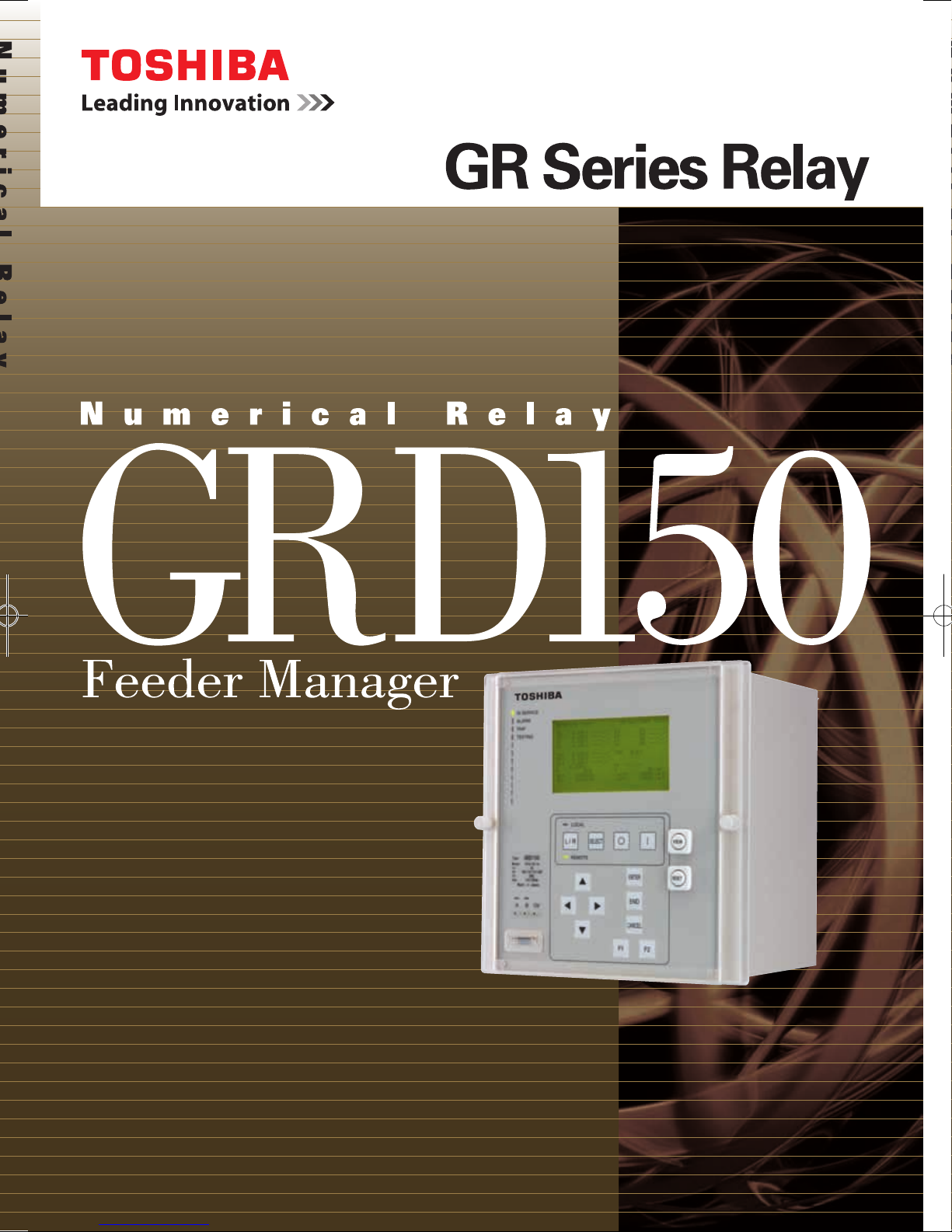
APPLICATION
GRD150 feeder manager is designed for protection,
control, metering and supervision of medium voltage
networks.
GRD150 includes multiple, high accuracy, overcurrent
protection elements (for phase and/or earth fault) with
inverse time (IDMTL) and definite time delay (DTL)
functions. All phase, earth and sensitive earth fault
overcurrent elements can be independently subject to
directional control. The directional elements provide
user-settable characteristic angles.
Other protection functions are also available, including
thermal protection to IEC60255-8, negative sequence
overcurrent protection, under/overvoltage and under/
over frequency protections.
GRD150 provides continuous monitoring of internal
circuits and of software. External circuits are also
monitored, by trip circuit supervision, CT and VT
supervision, and CB condition monitoring features.
A user-friendly HMI is provided through a backlit LCD,
programmable LEDs, keypad and menu-based
operating system. PC access is also provided, either
for local connection via a front-mounted RS232 port,
or for remote connection via a rear-mounted RS485
or fibre optic port. The communication system allows
the user to read and modify the relay settings, and to
access data gathered by the relay’s metering and
recording functions.
Data available either via the relay HMI or communications
ports includes the following functions.
Metering
Fault recording
Event recording
Alarm recording
Disturbance recording (available via
communications ports)
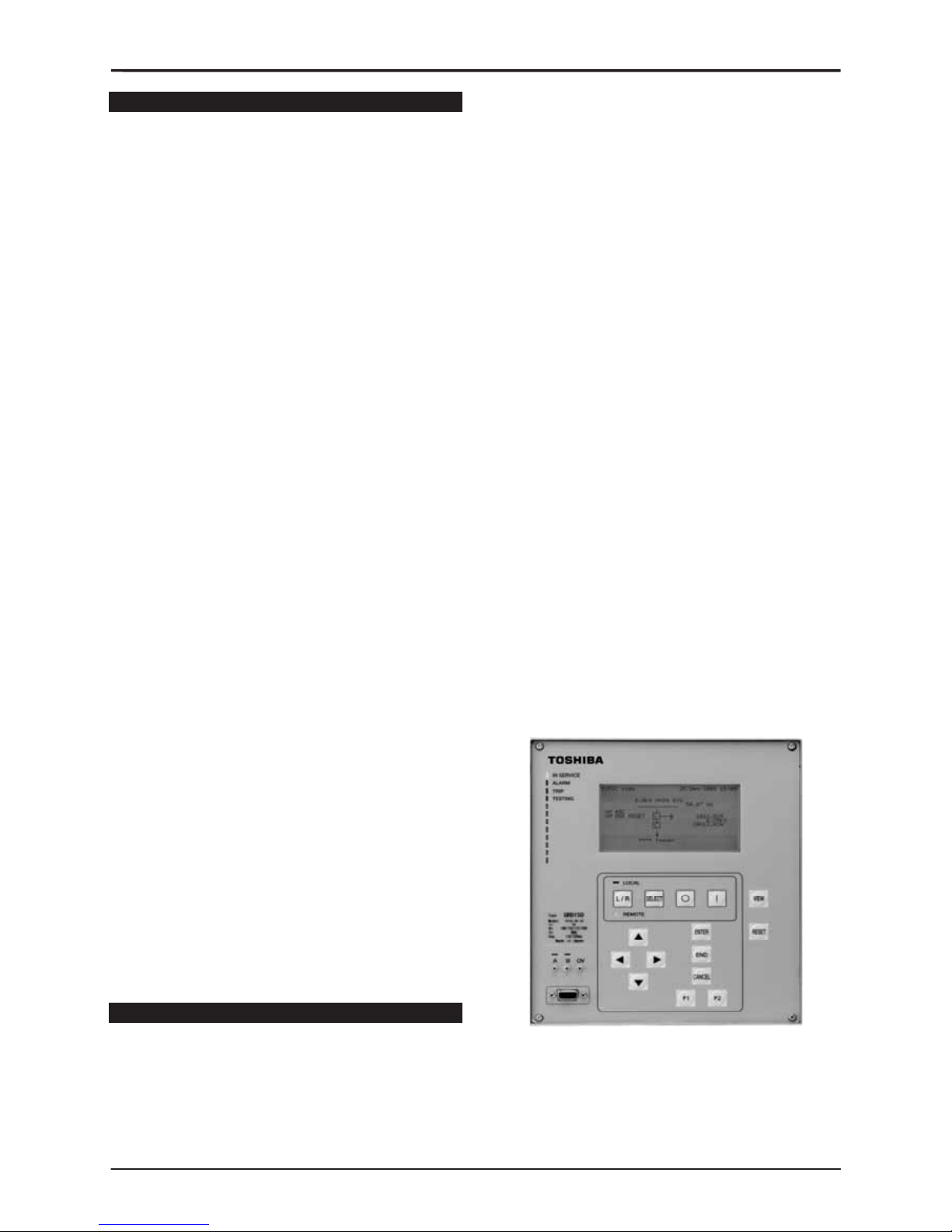
Figure 1 - Front View

GRD150
3
Table 1 GRD150 models and Functions
GRD150- Models
Function
10∗ series 20∗ series 30∗ series 40∗ series
Non-directional overcurrent OC (IDMTL, DTL, INST)
Non-directional earth fault EF (IDMTL, DTL, INST)
Non-directional sensitive earth fault SEF (IDMTL, DTL, INST)
Directional overcurrent DOC (IDMTL, DTL, INST)
Directional earth fault DEF (IDMTL, DTL, INST)
Directional sensitive earth fault DSEF (IDMTL, DTL, INST)
Undercurrent UC
Thermal over load THM
Non-directional negative phase overcurrent NOC (IDMTL, DTL, INST)
Directional negative phase overcurrent DNOC (IDMTL, DTL, INST)
Broken conductor detection BCD
Circuit breaker failure protection CBF
Cold load pick-up feature
Overvoltage OV (IDMTL, DTL, INST)
Undervoltage UV (IDMTL, DTL, INST)
Zero phase sequence overvoltage ZOV (IDMTL, DTL, INST)
Negative phase sequence overvoltage NOV (IDMTL, DTL, INST)
Under/over frequency FRQ
Autoreclose function
Fault locator
Indication of the status of switching devices
Open and close commands for switching devices
Synchronism check function
MIMIC configuration picture (*)
PLC function (*)
CT supervision
VT supervision
Trip circuit supervision
Self supervision
CB state monitoring
Trip counter alarm
∑Iy alarm
CB operate time alarm
Multiple settings groups
Metering
Fault records
Alarm records
Event records
Disturbance records
Communication
IDMTL: inverse definite minimum time
DTL: definite time
INST: instantaneous
(*): PC tools (MIMIC editor and PLC editor) are option.

GRD150
4
FUNCTIONS
Protection
- 4-stage non-directional and directional overcurrent
and earth-fault protection and sensitive earth fault
protection (option)
1
st
and 2nd stage: Instantaneous, IDMTL or DTL
3
rd
and 4th stage: Instantaneous or DTL
- 2-stage non-directional and directional negative
phase sequence overcurrent protection
1
st
stage: Instantaneous, IDMTL or DTL
2
nd
stage: Instantaneous or DTL
- 2-stage overvoltage and undervoltage protection
1
st
stage: Instantaneous, IDMTL or DTL
2
nd
stage: Instantaneous or DTL
- 6-stage underfrequency or overfrequency protection
- Thermal overload protection
- Cold load protection function or Inrush current (2
nd
harmonic) detector provided for energising the
system
- Undercurrent protection
- Broken conductor detection
- Circuit breaker failure protection
- Autoreclose function: 5-shots, 3-phase autoreclose
(option)
Control
Two-stepped operation (select-control) is used for the
control procedure of circuit breakers, disconnectors,
earthing disconnector switches and transformers to
ensure highly reliable operation.
- Control of circuit breakers, disconnectors and
earthing disconnector switches
- Interlock check
- Synchronism check for circuit breaker closing
(option)
- MIMIC configuration picture displayed on LCD
- Double command blocking
- Switchgear operation counter
- Control blocking
Password protection is provided to operate above
functions.
Monitoring and Metering
- Status monitoring of switchgear devices and failure
monitoring of power apparatus, control equipment,
protection relays and ancillary equipment
- Metering: current, voltage, frequency, active power,
reactive power and max. demand values
An energy calculation (Watt-hour, var-hour) is also
available.
- Limit value checking of metering
- Opening and closing time monitoring
These data are available on the HMI and at a local or
remote PC.
Recording
- Event records: The most recent 480 time-tagged
events with 1ms resolution are stored.
- Alarm records: The most recent 32 time-tagged
alarms with 1ms resolution are stored.
- Fault records: The most recent 8 time-tagged faults
with 1ms resolution are stored.
- Disturbance records: GRD150 can record 9 analog
and 32 binary signals, initiated by relay tripping. Pretrigger and post-trigger recording times can be set,
and the maximum number of records which can be
stored is dependent on the recording times chosen.
These records are available on the HMI and at a local
or remote PC.
GRD150
5
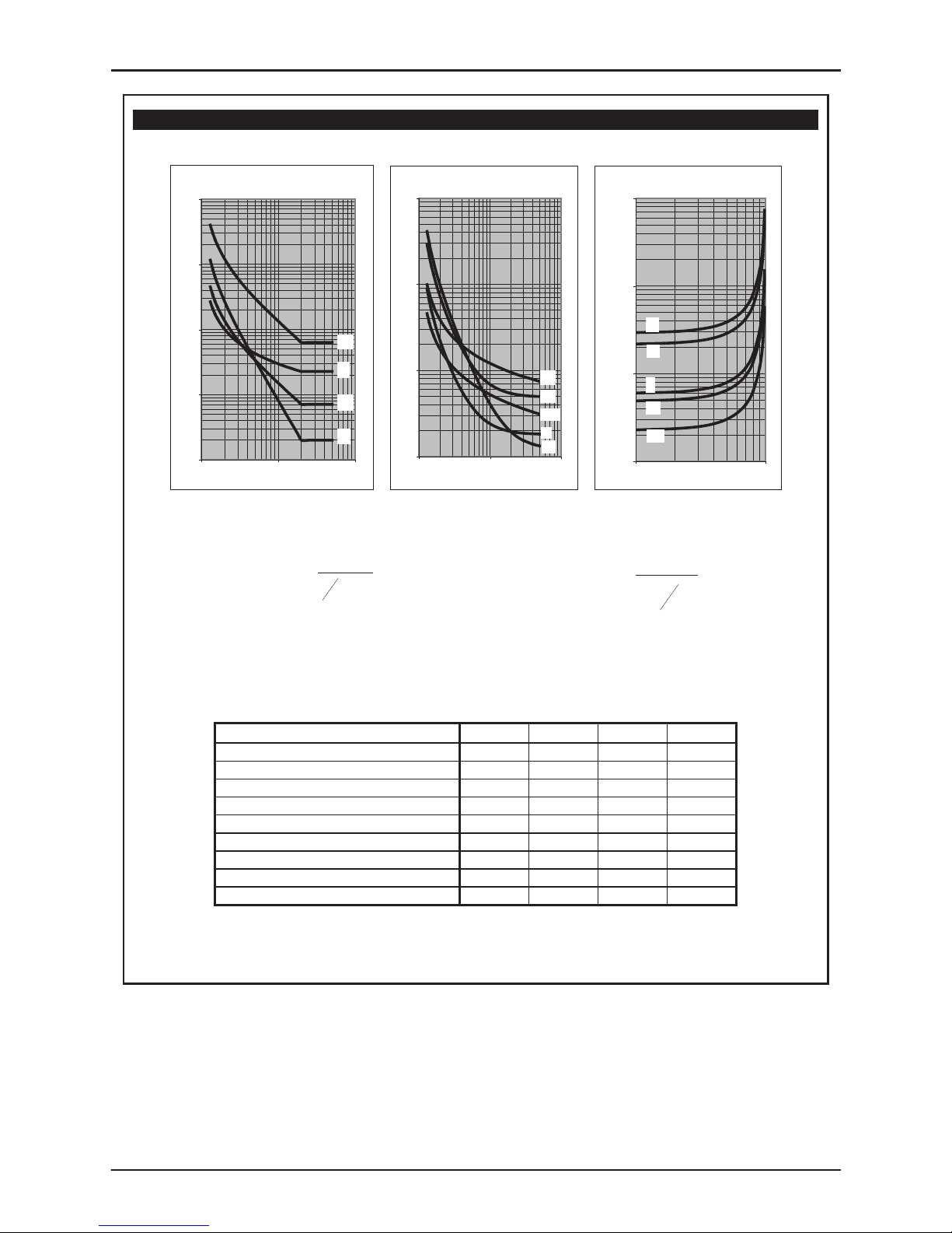
Figure 2 - Operate and Reset Characteristics of IDMTL
Inverse Time Operate and Reset Curves
IEC/UK Inverse Curves
(Time Muliplier TMS = 1)
0.1
1
10
100
1000
1 10 100
Current (Multiple of Setting)
Operating Time (s)
LTI
NI
VI
EI
IEEE/US Inverse Curves
(Time Multiplier TMS = 1)
0.1
1
10
100
1 10 100
Current (Multiple of S etting)
Operating Time (s)
MI
VI
STI
I
EI
IEEE/US Reset Curves
(Time Multiplier T MS = 1)
1.00
10.00
100.00
1000.00
0.1 1
Current (Multiple of S etting)
Time (s)
MI
VI
EI
STI
I
()
⎪
⎭
⎪
⎬
⎫
⎪
⎩
⎪
⎨
⎧
+
⎥
⎥
⎥
⎦
⎤
⎢
⎢
⎢
⎣
⎡
−
×= c
Is
I
k
TMSt
1
α
⎥
⎥
⎥
⎥
⎦
⎤
⎢
⎢
⎢
⎢
⎣
⎡
⎟
⎠
⎞
⎜
⎝
⎛
−
×=
2
1
S
r
I
I
t
RTMSt
Inverse time operate function Dependent time reset function
Constants for dependent time curves
Curve Description k
α
C t
r
IEC Normal Inverse (NI)
0.14 0.02 0 -
IEC Very Inverse (VI)
13.5 1 0 -
IEC Extremely Inverse (EI)
80 2 0 -
UK Long Time Inverse (LTI)
120 1 0 -
IEEE Moderately Inverse (MI)
0.0515 0.02 0.114 4.85
IEEE Very Inverse (VI)
19.61 2 0.491 21.6
IEEE Extremely Inverse (EI)
28.2 2 0.1217 29.1
US CO8 Inverse (I)
5.95 2 0.18 5.95
US CO2 Short Time Inverse (STI)
0.02394 0.02 0.01694 2.261
GRD150
6
USER INTERFACE
Relay Front Panel
A user friendly interface is provided on the relay front
panel. A menu-based system provides for easy
programming of relay functions and access to realtime and stored data. The front panel includes the
following features.
Graphical LCD
display with backlight.
12 LEDs including 8
user programmable
LEDs.
Keypad.
RS232C serial port for connection of local PC.
Local PC Connection
The user can communicate with the GRD150 from a
local PC via the RS232C port on the front panel. Using
RSM100 software, the user can view and modify
settings, monitor real-time metering and analyse
recorded data.
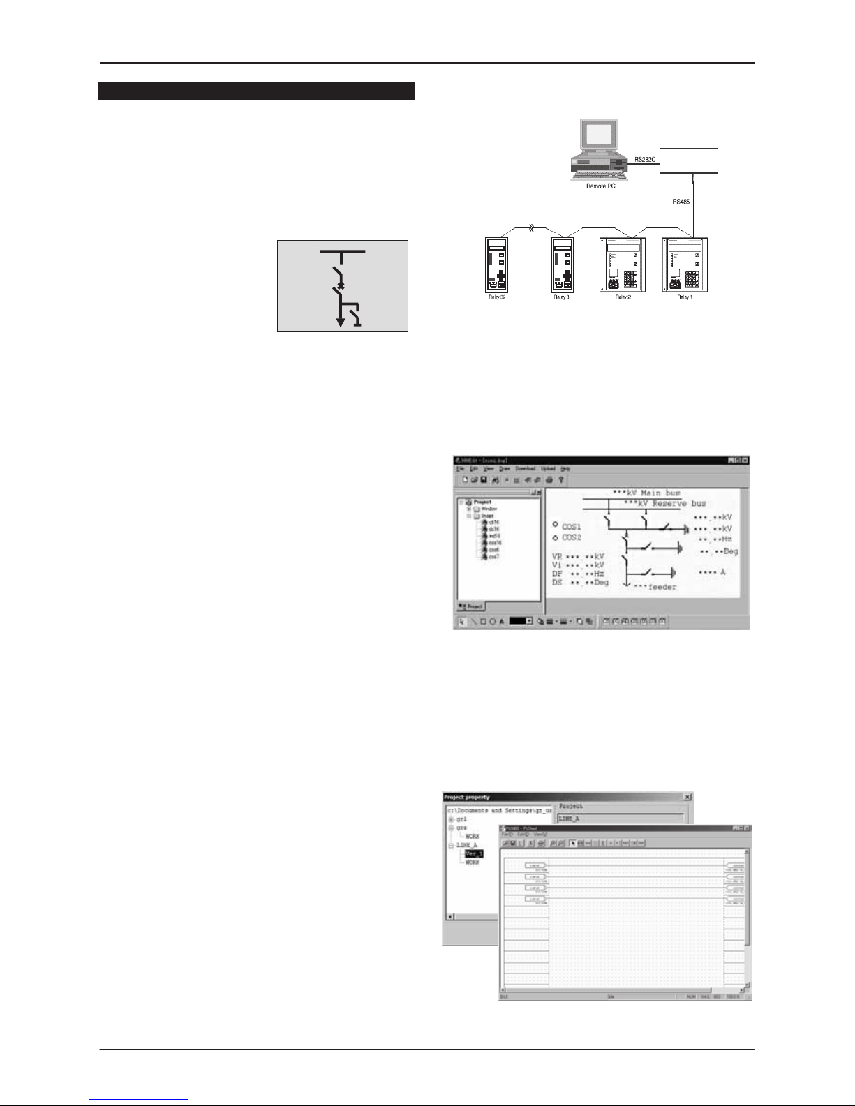
Relay Setting and Monitoring (RSM)
and Remote Control System
GRD150 can be connected to the RSM system via
the rear mounted serial communications port, using
RS485 or other connections such as fibre optic,
Ethernet LAN, etc., (specified at time of order). Using
RSM100 software, the user can view and modify
settings, monitor real-time metering and analyse
recorded data.
A maximum of 32 relays can be connected to the
remote PC in multi-drop mode, by connection via a
protocol converter, with data transmission rate of
64kbps using RSM-X protocol. Modbus®(RTU) protocol
can be also available.
The figures below show the configuration of the RSM
system and typical displays from the RSM100 software.
Using an additional port (option), GRD150 can be
connected to a Substation Control System. In this
case, GRD150 supports IEC60870-5-103 or DNP3.0
transmission protocols.
Figure 3 - Relay Setting and Monitoring System
Mimic Editor (MMEdit)
Yhe user can configure and customize the MIMIC
data displayed on the LCD of GRD150 using
MMEdit software. The MIMIC data produced by the
MMEdit software can be uploaded to GRD150 via the
PC communication port (RS232C).
Figure 4 - PC Display of MMEdit
PLC Editor (PLCEdit)
The user can customize logic functions on GRD150
such as trip and interlock sequence, etc., using
PLCEdit software. The PLC data produced by the
PLCEdit software can be uploaded to GRD150 via PC
communication port (RS232C).
Figure 5 - PC Display of PLCEdit
Converter
G1PR2
 Loading...