

GRD130
2
FEATURES
Phase undervoltage protection with IDMTL or
DTL.
Phase overvoltage protection with IDMTL or
DTL.
Zero phase sequence overvoltage (neutral voltage
displacement) protection with IDMTL/DTL.
Negative phase sequence overvoltage protection
with IDMTL or DTL.
Programmable reset characteristics.
Four settings groups.
Configurable binary inputs and outputs.
Circuit breaker condition monitoring.
Trip circuit supervision.
Automatic self-supervision.
Menu-based HMI system.
Configurable LED indication.
Metering and recording functions.
Communications for remote setting and data
download is provided via the RSM (Relay Setting
and Monitoring system.
Front mounted RS232 serial port for local PC
communications.
Rear mounted RS485 or fibre optic serial port
for remote PC communications.
The IEC60870-5-103 protocol is provided for
communication with substation control and
automation systems.
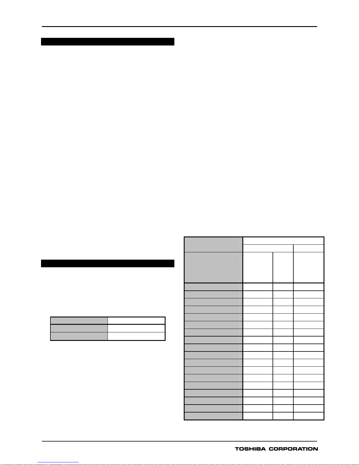
APPLICATION
The GRD130 is a range of fully numeric voltage
protection relays. GRD130 has two models which
differ according to the number of voltage inputs fitted,
see Table 1.
Table 1 - GRD130 Models
Model Configuration
GRD130-210 2 pole
GRD130-410 4 pole
Both models include multiple, high accuracy, phase
under/overvoltage protection with inverse time and
definite time delay functions. Voltage inputs can be
configured for phase to phase or phase to neutral
operation. Zero sequence overvoltage (neutral voltage
displacement) protection is available for detection of
earth faults in high impedance earthed or isolated
systems. For protection against operation on unbalanced
supply voltages, negative phase sequence overvoltage
protection is also available. The ZPS and NPS
overvoltage protections are available depending on
the model and on the configuration selected, see
Table 2.
GRD130 provides continuous monitoring of internal
circuits and of software. External circuits are also
monitored, by trip circuit supervision and CB condition
monitoring features.
A user-friendly HMI is provided through a backlit LCD,
programmable LEDs, keypad and menu-based operating
system. PC access is also provided, either for local
connection via a front-mounted RS232 port, or for
remote connection via a rear-mounted RS485 or fibre
optic port. The communication system allows the user
to read and modify the relay settings, and to access
data gathered by the relay’s metering and recording
functions.
Data available either via the relay HMI or communications
ports includes the following functions.
Metering
Fault recording
Event recording
Disturbance recording (available via
communications ports)
Table 2 - GRD130 Features
GRD130 - Model Number
210 410
Configuration 1V
ph-ph
+ V
0
1V
ph-n
+ V0
2V
ph-ph
3V
ph-n
3V
ph-n
+ V
0
3V
ph-ph
+ V
0
2V
ph-ph
+ V
0
Phase O/V (IDMTL) 59
Phase O/V (DTL) 59
Phase U/V (IDMTL) 27
Phase U/V (DTL) 27
ZPS O/V (IDMTL) 59N -
ZPS O/V (DTL) 59N -
NPS O/V (IDMTL) 47 -
NPS O/V (DTL) 47 -
Trip circuit supervision
Self supervision
CB State Monitoring
Trip Counter Alarm
Multiple settings groups
Metering
Fault records
Event records
Disturbance records
Communication
GRD130
3
PROTECTION FUNCTIONS
Phase Overvoltage Protection
GRD130 overvoltage protection provides three
independent overvoltage thresholds. The first and
second thresholds may be set for inverse time or
definite time operation. The third threshold can be
programmed for definite time operation.
The first and second thresholds has a programmable
reset feature, selectable for instantaneous or definite
time operation. Each element gives outputs for alarm
and trip, and each trip output can be inhibited by
binary input.
Phase Undervoltage Protection
GRD130 undervoltage protection provides three
independent undervoltage thresholds. The first and
second thresholds may be set for inverse time or
definite time operation. The third threshold can be
programmed for definite time operation.
The first and second thresholds has a programmable
reset feature, selectable for instantaneous or definite
time operation. Each element gives outputs for alarm
and trip, and each trip output can be inhibited by
binary input.
An undervoltage blocking function prevents undervoltage
tripping in the case of a dead line.
Zero Phase Sequence Overvoltage
Protection (ZPS)
GRD130 provides ZPS protection with two independent
overvoltage thresholds. The two thresholds may be
set for inverse time or definite time operation. The two
thresholds have a programmable reset feature,
selectable for instantaneous or definite time operation.
In the case of GRD130-410, the zero sequence voltage,
V
0
may either be calculated from the three measured
phase voltages, or it may be measured directly in the
form of the system residual voltage, typically using a
five limb VT.
In the case of GRD130-210, the V
0
must be measured
directly.
The low voltage settings which may be applied make
the ZPS element susceptible to any 3
rd
harmonic
component which may be superimposed on the input
signal. Therefore, a 3
rd
harmonic filter is provided to
suppress such superimposed components.
Each element gives outputs for alarm and trip, and
each trip output can be inhibited by binary input.
Negative Phase Sequence Overvoltage
Protection (NPS)
GRD130 provides NPS protection with two independent
overvoltage thresholds. The two thresholds may be
set for inverse time or definite time operation.
The two thresholds have a programmable reset
feature, selectable for instantaneous or definite time
operation. Each element gives outputs for alarm and
trip, and each trip output can be inhibited by binary
input.
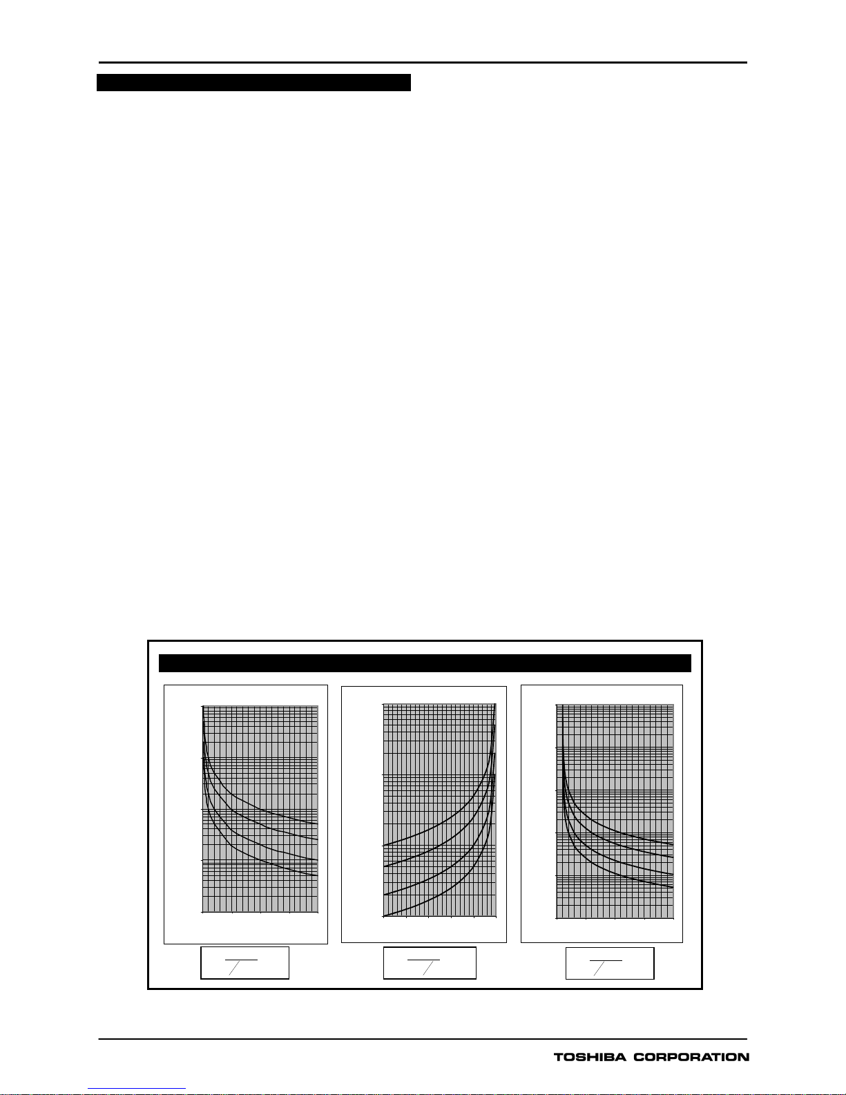
Figure 1 - IDMT curves for Overvoltage, Undervoltage and ZPS, NPS Overvoltage
Inverse Time Operate Curves
Overv oltage Inv erse Time Curv es
0.100
1.000
10.000
100.000
1000.00 0
1 1.5 2 2.5 3
Applied Voltage (x Vs)
Operating Time (secs)
TMS = 1
TMS = 2
TMS = 5
TMS = 10
Undervoltage Inverse Time Curves
1.000
10.000
100.000
1000.000
0 0.2 0.4 0.6 0.8 1
Applied Voltage (x Vs)
Operating Time (secs)
TMS = 10
TMS = 5
TMS = 2
TMS = 1
ZPS, NPS Overvoltage Inverse T ime Curves
0.010
0.100
1.000
10.000
100.000
1000.000
0 5 10 15 20
Applied Voltage (x Vs)
Operating Time (secs)
TMS = 10
TMS = 5
TMS = 2
TMS = 1
()
xTM
S
Vs
V
t
11−
=
()
xTMS
Vs
V
t−=
1
1
()
xTM
S
Vs
V
t
11−
=
GRD130
4
MONITORING FUNCTIONS
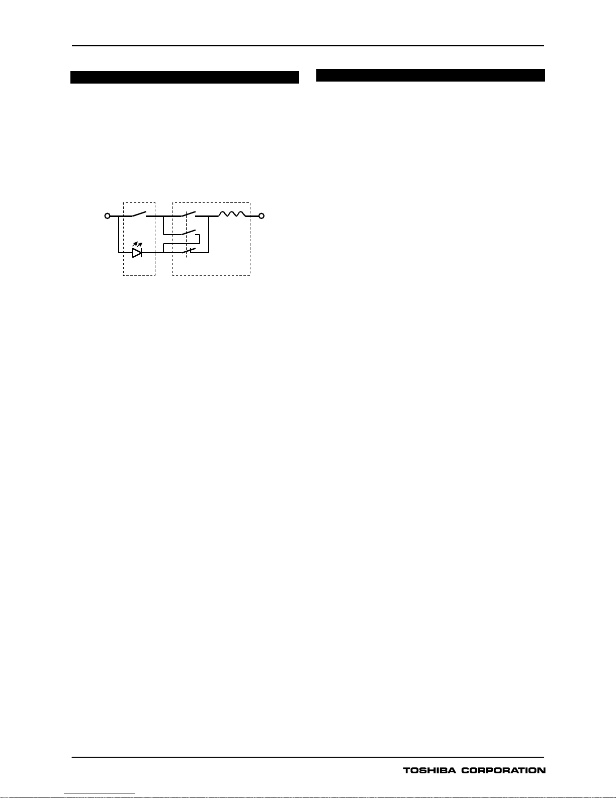
Trip Circuit Supervision
The circuit breaker tripping control circuit can be
monitored by a binary input. Figure 2 shows a typical
scheme. When the trip circuit is complete, a small
current flows through the binary input, the circuit breaker
auxiliary contacts and the trip coil. This current flows
for both the breaker open and closed conditions.
Figure 2 - Trip Circuit Supervision Scheme
If the trip supply is lost or if a connection becomes
open circuit then the binary input resets and a Trip
Circuit Fail alarm is given in the form of an output
contact operation and LCD or LED indication.
Automatic Self-Supervision
Automatic monitoring of internal circuits and software
is provided. In the event of a failure being detected,
the ALARM LED on the relay fascia is illuminated, the
‘RELAY FAILURE’ binary output operates, and the
date and time of the failure is recorded in the event
record.
Circuit Breaker State Monitoring
If two binary inputs are programmed to the functions
‘CB OPEN’ and ‘CB CLOSED’ then the CB State
Monitoring function becomes active. In normal
circumstances these inputs are in opposite states. If
both show the same state then a ‘CB Defective’ alarm
is raised.
Trip Counter Alarm
The trip counter increments the number of tripping
operations performed, and an alarm is issued when
the count exceeds a user-defined setting. The trip
count is triggered each time a trip is issued, and they
can also be triggered by an external device via a
binary input.
METERING AND RECORDING
Metering
The following data is continuously available on the relay
fascia LCD and at a local or remote PC.
Primary and secondary voltages for each input.
Positive and negative phase sequence voltages.
Power frequency.
CB trip count.
CB status.
Relay element output status.
Binary input and output status.
Event Record
Records are stored for the 480 most recent events,
time-tagged to 1ms resolution. The event record is
available on the relay fascia LCD and at a local or
remote PC. Events are recorded as follows:
Tripping operations.
Alarms.
Operation of protection elements.
Change of state of binary inputs / outputs.
Change of relay setting.
Failure detected by automatic supervision.
Fault Record
A relay trip initiates fault recording. Records are stored
for the 8 most recent faults, time-tagged to 1ms
resolution. The fault record is available on the relay
fascia LCD and at a local or remote PC. Fault records
include the following data:
Date and time of trip operation.
Faulted phase.
Protection element responsible for trip.
Measured voltage data.
Disturbance Record
The relay can record 4 analog and 32 binary signals,
initiated by relay tripping. The post-trigger recording time
can be set, and the maximum number of records which
can be stored is dependent on the recording time
chosen.
Date and Time
GRD130 provides a date and time feature for tagging
of records.
GRD110
Circuit Breaker
Binar y
Input
CB Aux.
Contac ts
CB Trip Coil Tr ip Out put +ve Trip
Suppl y
-ve Trip
Suppl y
GRD130
5
USER INTERFACE
Relay Front Panel
A user friendly interface is provided on the relay front
panel. A menu-based system provides for easy
programming of relay functions and access to realtime and stored data. The front panel includes the
following features.
16 character, 2-line LCD with backlight.
6 LEDs.
Keypad.
RS232C serial port for connection of local PC.
Local PC Connection
The user can communicate with the GRD130 from a
local PC via the RS232C port on the front panel. Using
RSM100 software, the user can view and modify
settings, monitor real-time metering and analyse
recorded data.
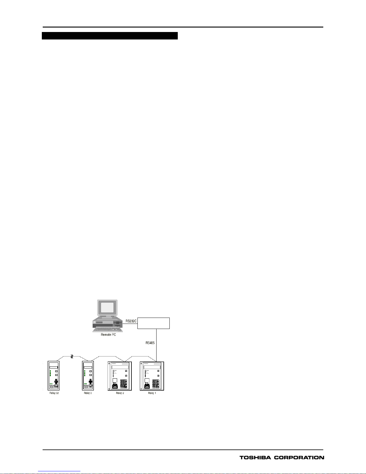
Relay Setting and Monitoring (RSM)
GRD130 can be connected to the RSM system via the
rear mounted serial communications port, using either
RS485 or fibre optic connections (specified at time of
order). Using RSM100 software, the user can view and
modify settings, monitor real-time metering and analyse
recorded data.
A maximum of 32 x 8 relays can be connected to the
remote PC in multi-drop mode, by connection via a
protocol converter G1PR2, with a maximum data
transmission rate of 64kbps. The G1PR2 can be
provided with maximum 8 ports and each port
supports maximum 32 relays addressing.
Figure 3 - Relay Setting and Monitoring System
Figure 3 and 4 show the configuration of the RSM
system and typical displays from the RSM100 software.
IEC60870-5-103 Communications
GRD130 supports the IEC60870-5-103
communication protocol. This protocol is used for
communication with a substation control and
monitoring system and is used to transfer measurand
data, status data and general commands between the
relay and the control system.
Relay Setting
The user can modify relay settings either using the
front panel keypad or using the RSM100 software from
a local or remote PC. Password protection is available
for added security.
Four settings groups are provided, allowing the user to
set one group for normal conditions, while the other
groups may be set to cover alternative operating
conditions.
Using the RSM software, the user can create a settings
file on a PC (without being connected to a relay), and
store the file ready for download to a relay at a later
date.
Binary Outputs
GRD130 provides eight binary output contacts for
tripping and alarm, of which seven are user
programmable. Each of the programmable binary
outputs is driven via a logic gate which can be
programmed for OR gate or AND gate operation.
Further, each output has a programmable reset
characteristic, settable for instantaneous drop-off,
delayed drop-off, or for latching operation. If latching
operation is selected then an operated relay must be
reset by the user, either by pressing the RESET
button, by energising a binary input which has been
programmed for ‘Remote Reset’ operation, or by a
communications command.
Binary Inputs
GRD130 provides eight programmable binary inputs.
Each binary input is individually user-programmable
for normal or inverted operation and for delayed pickup and/or drop-off. Each input can also be used to
switch relay operation to a different settings group.
General purpose alarm functions are also included.
The user can define a text message for each alarm.
Then when inputs associated with that alarm are raised,
the defined text is displayed on the LCD.
G1PR2
Protocol converter

GRD130
6
Figure 4 - Relay Setting and Monitoring System - PC Displays
PC DISPLAY
Setting Event record
Metering Fault record
GRD130
7
TECHNICAL DATA
Ratings
AC voltage Vn: 110V
Frequency: 50Hz or 60Hz
DC auxiliary supply: 110/125Vdc (Operative range: 88 - 150Vdc)
220/250Vdc (Operative range: 176 - 300Vdc)
48/54/60Vdc (Operative range: 38.4 - 72Vdc)
Superimposed AC ripple on DC supply: maximum 12%
DC supply interruption: maximum 50ms at 110V
Binary input circuit DC voltage: 110/125Vdc (Operative range: 88 - 150Vdc)
220/250Vdc (Operative range: 176 - 300Vdc)
48/54/60Vdc (Operative range: 38.4 - 72Vdc)
Overload Ratings
AC voltage inputs: 2 times rated voltage continuous
Burden
AC phase voltage inputs: ≤ 0.1VA (at rated voltage)
DC power supply: ≤ 10W (quiescent), ≤ 15W (maximum)
Binary input circuit: ≤ 0.5W per input at 110Vdc
Overvoltage Protection
1st, 2nd, 3rd Overvoltage thresholds: OFF, 10.0 – 200.0V in 0.1V steps
Delay type (1st threshold only): DTL, IDMTL
IDMTL Time Multiplier Setting TMS: 0.05 - 100.00 in 0.01 steps
DTL delay: Inst, 0.01 - 300.00s in 0.01s steps
DO/PU ratio 10 - 98% in 1% steps
Reset Delay (1st threshold only): Instantaneous, 0.1 – 300.0s in 0.1s steps
Undervoltage Protection
1st, 2nd, 3rd Undervoltage thresholds: OFF, 5.0 – 130.0V in 0.1V syeps
Delay type (1st threshold only): DTL, IDMTL
IDMTL Time Multiplier Setting TMS: 0.05 - 100.00 in 0.01 steps
DTL delay: Inst, 0.01 - 300.00s in 0.01s steps
Reset Delay (1st threshold only): Instantaneous, 0.1 – 300.0s in 0.1s steps
Zero Sequence Overvoltage (ZPS) Protection
1st, 2nd ZPS Overvoltage thresholds: OFF, 1.0 – 160.0V in 0.1V steps
Delay type (1st threshold only): DTL, IDMTL
IDMTL Time Multiplier Setting TMS: 0.05 - 100.00 in 0.01 steps
DTL delay: Inst, 0.01 - 300.00s in 0.01s steps
Reset Delay (1st threshold only): Instantaneous, 0.1 – 300.0s in 0.1s steps
Negative Sequence Overvoltage (NPS) Protection
1st, 2nd NPS Overvoltage thresholds: OFF, 1.0 – 160.0V in 0.1V steps
Delay type (1st threshold only): DTL, IDMTL
IDMTL Time Multiplier Setting TMS: 0.05 - 100.00 in 0.01 steps
DTL delay: Inst, 0.01 - 300.00s in 0.01s steps
Reset Delay (1st threshold only): Instantaneous, 0.1 – 300.0s in 0.1s steps
Accuracy
IDMTL Overvoltage Pick-up: 105% of setting ± 5%
All Other Overvoltage Pick-ups: 100% of setting ± 5%
Overvoltage PU/DO ratio: ≥95% (settable for phase overvoltage)
IDMTL Undervoltage Pick-up: 95% of setting ± 5%
All Other Undervoltage Pick-ups: 100% of setting ± 5%
Undervoltage PU/DO ratio: ≤105%
Inverse Time Delays: ± 5% or 30ms
Definite Time Delays: ± 1% or 10ms

GRD130
8
Front Communication port - local PC (RS232)
Connection: Point to point
Cable type: Multi-core (straight)
Cable length: 15m (max.)
Connector: RS232C 9-way D-type female
Rear Communication port - remote PC (RS485)
Connection: Multidrop (max. 32 relays)
Cable type: Twisted pair
Cable length: 1200m (max.)
Connector: Screw terminals
Isolation: 1kVac for 1 min.
Transmission rate: 64kpbs for RSM system
9.6, 19.2kbps for IEC60870-5-103
Rear Communication port - remote PC (Fibre Optic for IEC60870-5-103: option)
Connection: Multidrop (max. 32 relays)
Cable type: 50/125 or 62.5/125µm fibre
Cable length: 1000m (max.)
Connector: ST
Transmission rate: 9.6, 19.2kbps for IEC60870-5-103
Binary Inputs
Operating voltage Typical 74Vdc(min. 70Vdc) for 110V/125Vdc rating
Typical 138Vdc(min. 125Vdc) for 220V/250Vdc rating
Typical 31Vdc(min. 28Vdc) for 48V/54V/60Vdc rating
Binary Outputs
Number 8
Ratings: Make and carry: 4A continuously
Make and carry: 20A, 290Vdc for 0.5s (L/R≥5ms)
Break: 0.1A, 290Vdc (L/R=40ms)
Durability: Loaded contact: 10000 operations
Unloaded contact: 100000 operations
Mechanical design
Weight 4.5kg
Case color Munsell No. 10YR8/0.5
Installation Flush mounting
ENVIRONMENTAL PERFORMANCE
Test Standards Details
Atmospheric Environment
Temperature IEC60068-2-1/2
Operating range: -10°C to +55°C.
Storage / Transit: -25°C to +70°C.
Humidity IEC60068-2-3
56 days at 40°C and 93% relative humidity.
Enclosure Protection IEC60529 IP50 – Dust Proof
Mechanical Environment
Vibration IEC60255-21-1
Response - Class 1
Endurance - Class 1
Shock and Bump IEC60255-21-2
Shock Response Class 1
Shock Withstand Class 1
Bump Class 1
Seismic IEC60255-21-3 Class 1

GRD130
9
Test Standards Details
Electrical Environment
Dielectric Withstand IEC60255-5
2kVrms for 1 minute between all terminals and earth.
2kVrms for 1 minute between independent circuits.
1kVrms for 1 minute across normally open contacts.
High Voltage Impulse IEC60255-5
Three positive and three negative impulses of
5kV(peak), 1.2/50µs, 0.5J between all terminals and
between all terminals and earth.
Electromagnetic Environment
High Frequency
Disturbance / Damped
Oscillatory Wave
IEC60255-22-1 Class 3,
IEC61000-4-12 /
EN61000-4-12
1MHz 2.5kV applied to all ports in common mode.
1MHz 1.0kV applied to all ports in differential mode.
Electrostatic
Discharge
IEC60255-22-2 Class 3,
IEC61000-4-2 /
EN61000-4-2
6kV contact discharge, 8kV air discharge.
Radiated RF
Electromagnetic
Disturbance
IEC60255-22-3 Class 3,
IEC61000-4-3 /
EN61000-4-3
Field strength 10V/m for frequency sweeps of 80MHz
to 1GHz and 1.7GHz to 2.2GHz. Additional spot tests
at 80, 160, 450, 900 and 1890MHz.
Fast Transient
Disturbance
IEC60255-22-4,
IEC61000-4-4 /
EN61000-4-4
4kV, 2.5kHz, 5/50ns applied to all inputs.
Surge Immunity
IEC60255-22-5,
IEC61000-4-5 /
EN61000-4-5
1.2/50µs surge in common/differential modes:
HV ports: 4kV/2kV (peak)
PSU and I/O ports: 2kV/1kV (peak)
RS485 port: 1kV/0.5kV (peak)
Conducted RF
Electromagnetic
Disturbance
IEC60255-22-6 Class 3,
IEC61000-4-6 /
EN61000-4-6
10Vrms applied over frequency range 150kHz to
100MHz. Additional spot tests at 27 and 68MHz.
Power Frequency
Disturbance
IEC60255-22-7,
IEC61000-4-16 /
EN61000-4-16
300V 50Hz for 10s applied to ports in common mode.
150V 50Hz for 10s applied to ports in differential
mode.
Not applicable to AC inputs.
Conducted and
Radiated Emissions
IEC60255-25,
EN55022 Class A,
IEC61000-6-4 /
EN61000-6-4
Conducted emissions:
0.15 to 0.50MHz: <79dB (peak) or <66dB (mean)
0.50 to 30MHz: <73dB (peak) or <60dB (mean)
Radiated emissions (at 30m):
30 to 230MHz: <30dB
230 to 1000MHz: <37dB
European Commission Directives
89/336/EEC
Compliance with the European Commission
Electromagnetic Compatibility Directive is
demonstrated according to EN 61000-6-2 and EN
61000-6-4.
73/23/EEC
Compliance with the European Commission Low
Voltage Directive is demonstrated according to EN
50178 and EN 60255-5.

GRD130
10
ORDERING
Under/Overvoltage Relay
Type:
Under/Overvoltage Relay GRD130
Model:
Two pole 210
Four pole 410
Frequency:
50Hz 1
60Hz 2
DC auxiliary supply rating:
110V/125V 1
220V/250V 2
48V/54V/60V 3
Rear communication port:
RS485 1
Fibre optic 2
Dual RS485 3
RS485 + Fibre optic 9
∗
GRD130
0

GRD130
11
TYPICAL APPLICATIONS / CONNECTIONS
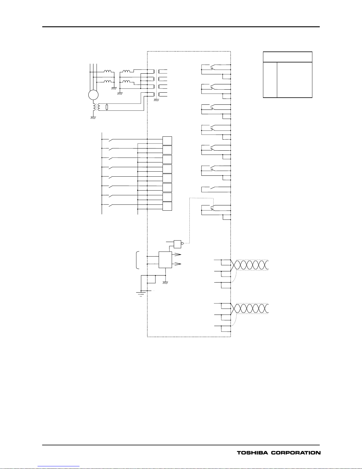
Figure 5 - GRD130-210 Typical Application Diagram for Single Phase-to-Phase
Voltage and Direct Neutral Connection
OUTPUT CONTACTS
SIGNAL LIST (DEFAULT)
BO1
BO2
BO3
BO4
BO5
BO6
BO7
GENERAL TRIP
GENERAL TRIP
GENERAL TRIP
GENERAL TRIP
UV1 TRIP
UV1 TRIP
ZPS1 TRIP
A
4
BO1
A
5
B5
A7
B7
BO2
A
6
B6
B8
A
8
BO3
A
9
B9
A
10
B10
BO4
A
11
B11
A13
B13
BO5
A
12
B12
B14
BO6
A
15
B15
A16
B16
BO7
B17
A
17
FAIL
A
18
B18
TB3-
B4
(P)
B1
BI1
B2
BI2
B3
BI3
A2A
3
B4
BI4
A
4
B5
BI5
A
5
B6
BI6
A
6
B7
BI7
A
7
B8
BI8
A
8
TB2-
A
1
(N)
BI1 COMMAND
BI2 COMMAND
BI3 COMMAND
BI4 COMMAND
BI5 COMMAND
BI6 COMMAND
BI7 COMMAND
BI8 COMMAND
4
3
2
FRAME EARTH
V
∆
V
N
TB11
A
B
C
DD FAIL.
(-
)
(+)
+5Vdc
0V
DC
SUPPLY
DC-DC
RELAY FAIL.
≥1
TB2- A9
B9
CASE EARTH
E
A10
B10
FRAME EARTH
TB4-A2
COM2-B
COM2-A
RS485 I/F for IEC60870-5-103
(Dual RS485 model only)
A1
A3
B3
COM2-0V
B1
B2
TB3-A2
COM1-B
COM1-A
RS485 I/F for RSM, IEC60870-5-103
A1
A3
B3
COM1-0V
B1
B2

GRD130
12
Figure 6 - GRD130-210 Typical Application Diagram for Two Phase-to-Phase Voltage Connection
OUTPUT CONTACTS
SIGNAL LIST (DEFAULT)
BO1
BO2
BO3
BO4
BO5
BO6
BO7
GENERAL TRIP
GENERAL TRIP
GENERAL TRIP
GENERAL TRIP
UV1 TRIP
UV1 TRIP
ZPS1 TRIP
A
4
BO1
A
5
B5
A
7
B7
BO2
A
6
B6
B8
A
8
BO3
A
9
B9
A
10
B10
BO4
A
11
B11
A13
B13
BO5
A
12
B12
B14
BO6
A
15
B15
A16
B16
BO7
B17
A
17
FAIL
A
18
B18
TB3-
B4
(P)
B1
BI1
B2
BI2
B3
BI3
A2A
3
B4
BI4
A
4
B5
BI5
A
5
B6
BI6
A
6
B7
BI7
A
7
B8
BI8
A
8
TB2-
A
1
(N)
BI1 COMMAND
BI2 COMMAND
BI3 COMMAND
BI4 COMMAND
BI5 COMMAND
BI6 COMMAND
BI7 COMMAND
BI8 COMMAND
DD FAIL.
(-
)
(+)
+5Vdc
0V
DC
SUPPLY
DC-DC
RELAY FAIL.
≥1
TB2- A9
B9
CASE EARTH
E
A10
B10
FRAME EARTH
4
3
2
FRAME EARTH
V
AB
V
BC
TB11
A
B
C
TB4-A2
COM2-B
COM2-A
RS485 I/F for IEC60870-5-103
(Dual RS485 model only)
A1
A3
B3
COM2-0V
B1
B2
TB3-A2
COM1-B
COM1-A
RS485 I/F for RSM, IEC60870-5-103
A1
A3
B3
COM1-0V
B1
B2

GRD130
13
Figure 7 - GRD130-410 Typical Application Diagram for Three Phase to Neutral Voltage Connection
(Derived Zero Sequence Quantity)
OUTPUT CONTACTS
SIGNAL LIST (DEFAULT)
BO1
BO2
BO3
BO4
BO5
BO6
BO7
GENERAL TRIP
GENERAL TRIP
GENERAL TRIP
GENERAL TRIP
UV1 TRIP
UV1 TRIP
ZPS1 TRIP
A
4
BO1
A
5
B5
A7
B7
BO2
A
6
B6
B8
A
8
BO3
A
9
B9
A
10
B10
BO4
A
11
B11
A13
B13
BO5
A
12
B12
B14
BO6
A
15
B15
A16
B16
BO7
B17
A
17
FAIL
A
18
B18
TB3-
B4
(P)
B1
BI1
B2
BI2
B3
BI3
A2A
3
B4
BI4
A
4
B5
BI5
A
5
B6
BI6
A
6
B7
BI7
A
7
B8
BI8
A
8
TB2-
A
1
(N)
BI1 COMMAND
BI2 COMMAND
BI3 COMMAND
BI4 COMMAND
BI5 COMMAND
BI6 COMMAND
BI7 COMMAND
BI8 COMMAND
DD FAIL.
(-
)
(+
)
+5Vdc
0V
DC
SUPPLY
DC-DC
RELAY FAIL.
≥1
TB2- A9
B9
CASE EARTH
E
A10
B10
FRAME EARTH
A
B
C
4
3
2
6
5
FRAME EARTH
8
7
V
C
TB11
V
A
V
B
V
N
TB4-A2
COM2-B
COM2-A
RS485 I/F for IEC60870-5-103
(Dual RS485 model only)
A1
A3
B3
COM2-0V
B1
B2
TB3-A2
COM1-B
COM1-A
RS485 I/F for RSM, IEC60870-5-103
A1
A3
B3
COM1-0V
B1
B2
GRD130
14
Figure 8 - GRD130-410 Typical Application Diagram for Two Phase VT Connection with Residual Voltage
Measured by Earthing Transformer
OUTPUT CONTACTS
SIGNAL LIST (DEFAULT)
BO1
BO2
BO3
BO4
BO5
BO6
BO7
GENERAL TRIP
GENERAL TRIP
GENERAL TRIP
GENERAL TRIP
UV1 TRIP
UV1 TRIP
ZPS1 TRIP
A
4
BO1
A
5
B5
A7
B7
BO2
A
6
B6
B8
A
8
BO3
A
9
B9
A
10
B10
BO4
A
11
B11
A13
B13
BO5
A
12
B12
B14
BO6
A
15
B15
A16
B16
BO7
B17
A
17
FAIL
A
18
B18
TB3B4
(P)
B1
BI1
B2
BI2
B3
BI3
A2A
3
B4
BI4
A
4
B5
BI5
A
5
B6
BI6
A
6
B7
BI7
A
7
B8
BI8
A
8
TB2-
A
1
(N)
BI1 COMMAND
BI2 COMMAND
BI3 COMMAND
BI4 COMMAND
BI5 COMMAND
BI6 COMMAND
BI7 COMMAND
BI8 COMMAND
DD FAIL.
(-)
(+
)
+5Vdc
0V
DC
SUPPLY
DC-DC
RELAY FAIL.
≥1
TB2- A9
B9
CASE EARTH
E
A10
B10
FRAME EARTH
A
B
C
4
3
2
6
5
FRAME EARTH
8
7
V
C
TB11
V
A
V
B
V
N
G
TB4-A2
COM2-B
COM2-A
RS485 I/F for IEC60870-5-103
(Two ports model only)
A1
A3
B3
COM2-0V
B1
B2
TB3-A2
COM1-B
COM1-A
RS485 I/F for RSM, IEC60870-5-103
A1
A3
B3
COM1-0V
B1
B2

GRD130
15
RELAY OUTLINE
Figure 9 - GRD130 Outline Diagram
185.2
32
15.6
Side view
104
2 5 8
IN SERVICE
TRIP
ALARM
VIEW
RESET
Front view
END
CEL
CAN
ENTER
2 4 9
Panel cut-out
56
102
4 holes-φ5.5
2 3 9
4 holes-φ4.5
TB3
Rear view
E
TB1
TB2
TB4
TB1,TB2,TB3: Screw terminal
(M3.5 Ring)
TB4: Screw terminal
TB4 is provided only for dual
RS485 model.
Terminal block
TB3
A1 B1
A18 B18
1
2
3 4
5 6
TB1
TB2
A1
B1
A10
B10
7 8
A1 A3
TB4
B1
B3

Industrial and Power Systems & Services Company
1-1,SHIBAURA 1-CHOME,MINATO-KU, TOKYO 105-8001,JAPAN
PHONE;+81-3-3457-3644 FAX;+81-3-5444-9168
http://www.toshiba.co.jp/f-ene/tands/english/protect/f_pc_top.htm
6634-1 0508T1
Thedatagiveninthiscatalogaresubjecttochangewithoutnotice.
 Loading...