

Toshiba GRD110, GRD110-110, GRD110-400, GRD110-420, GRD110-500 User Manual
...
GRD110
2
FEATURES
Overcurrent protection for phase and earth
faults with IDMTL or DTL.
Three instantaneous elements with DTL.
Programmable reset characteristics.
Sensitive earth fault protection (SEF).
Restricted earth fault protection
Undercurrent protection with DTL.
Thermal overload protection.
Negative phase sequence overcurrent
protection (NPS).
Broken conductor detection.
Circuit breaker fail protection.
Inrush current detector for blocking differential
and/or overcurrent trip at energisation.
Cold load pick-up feature.
Five shot, three phase auto-reclose (six trips to
lockout).
Sequence co-ordination with in-series auto-
reclosing devices.
Four settings groups.
Configurable binary inputs and outputs.
Circuit breaker condition monitoring.
Trip circuit supervision.
Automatic self-supervision.
Menu-based HMI system.
Configurable LED indication.
Metering and recording functions.
Communication for remote setting and data
download is provided via the RSM (Relay
Setting and Monitoring) system.
Front mounted RS232 serial port for local PC
communications.
Rear mounted RS485 or fibre optic serial port
for remote PC communications.
The IEC60870-5-103 protocol is provided for
communication with substation control and
automation systems.
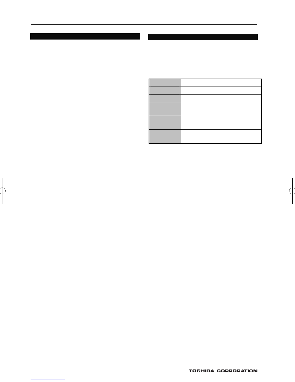
APPLICATION
The GRD110 is a range of fully numeric multi-function
protection relays. GRD110 has five models which
differ according to the number and type of current
inputs fitted, see
Table 1.
Table 1 - GRD110 Models
Model Configuration
GRD110-110 Earth Fault and Sensitive Earth Fault
GRD110-400 Three Phase Fault and Earth Fault
GRD110-420
Three Phase Fault, Earth Fault and
Sensitive Earth Fault
GRD110-500
Three Phase Fault and Earth Fault
and Auto-reclose
GRD110-520
Three Phase Fault, Earth Fault,
Sensitive Earth Fault, and Auto-reclose
All models include multiple, high accuracy, overcurrent
protection elements (for phase and/or earth fault) with
inverse time and definite time delay functions. Other
protection functions are available according to model
type, including phase undercurrent protection with
definite time delay, thermal protection to IEC60255-8,
negative sequence overcurrent protection and a broken
conductor detection feature, see
Table 2.
All models provide continuous monitoring of internal
circuits and of software. External circuits are also
monitored, by trip circuit supervision and CB condition
monitoring features.
A user-friendly HMI is provided through a backlit LCD,
programmable LEDs, keypad and menu-based operating
system. PC access is also provided, either for local
connection via a front-mounted RS232 port, or for remote
connection via a rear-mounted RS485 or fibre optic
port. The communication system allows the user to
read and modify the relay settings, and to access data
gathered by the relay’s metering and recording functions.
Data available either via the relay HMI or
communications ports includes the following functions.
Metering
Fault recording
Event recording
Disturbance recording (available via
communications ports)
GRD110
3
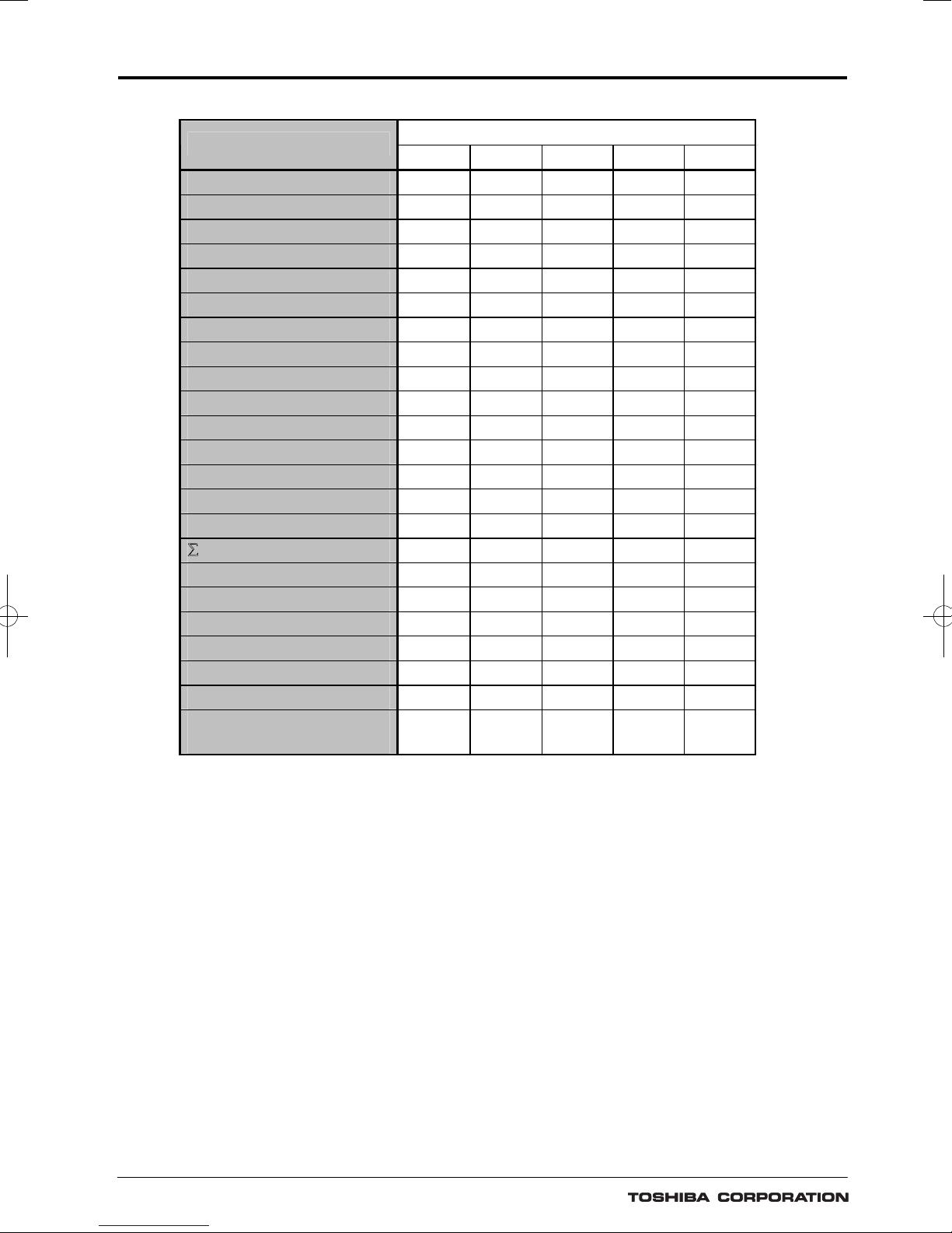
Table 2 - GRD110 Features
GRD110 -
Model Number
110 400 420 500 520
Phase Fault O/C (50/51P) 9 9 9 9
Earth Fault O/C (50/51N) 9 9 9 9 9
SEF (50/51N) 9 9 9
Phase Undercurrent (37P) 9 9 9 9
Thermal Overload (49) 9 9 9 9
NPS Overcurrent (46) 9 9 9 9
Broken Conductor 9 9 9 9
Circuit Breaker Fail (50BF) 9 9 9 9
Inrush current detector 9 9
Cold Load Protection 9 9 9 9
Auto-reclose (79) 9 9
Trip circuit supervision 9 9 9 9 9
Self supervision 9 9 9 9 9
CB State Monitoring 9 9 9 9 9
Trip Counter Alarm 9 9 9 9 9
¦Iy Alarm 9 9 9 9
CB Operate Time Alarm 9 9 9 9 9
Four settings groups 9 9 9 9 9
Metering 9 9 9 9 9
Fault records 9 9 9 9 9
Event records 9 9 9 9 9
Disturbance records 9 9 9 9 9
IEC60870-5-103
Communication
9 9 9 9 9

GRD110
4
PROTECTION FUNCTIONS
Phase Fault Overcurrent Protection
Models GRD110-400, 420, 500 and -520 can provide
two or three phase overcurrent protection. Each provides
four independent overcurrent thresholds. The first
and second thresholds may be set for inverse time or
definite time operation. If inverse time is selected,
then any one of nine curves may be chosen,
including IEC and IEEE/ ANSI standard
characteristics. Further, user configurable curve is
available, if required. See Figure 1.
The first and second thresholds have a
programmable reset feature, selectable for
instantaneous, definite time or dependent time reset.
This feature can be used to protect against flashing
fault conditions, or to grade correctly with
electromechanical overcurrent relays.
The other overcurrent thresholds may be set for
definite time, or instantaneous operation. These
elements are immune to the effects of transformer
magnetising inrush and dc offset transient over-reach.
All elements can be inhibited by binary input signals
for operation in blocked overcurrent schemes and
busbar zone blocking protection.
Earth Fault Protection
The standard earth fault protection is available in all
models, and provides four independent overcurrent
thresholds. Protection functionality is the same as for
the phase fault elements, only with more sensitive
current thresholds.
For models GRD110-110, 400 and -500 the earth
fault quantity is measured directly, either by
connecting the input in the residual circuit of the㩷 phase
CTs, or, as is recommended for more sensitive
settings, using a dedicated core balance earth fault
CT. For model GRD110-420 and -520, the standard
earth fault quantity is derived internally from the
residual sum of the three phases.
Sensitive Earth Fault Protection (SEF)
GRD110-110, 420 and -520 provide earth fault
protection with more sensitive settings for use in
applications where the fault current magnitude may
be very low. A 2-stage overcurrent function is
provided, with the first stage programmable for
inverse time or definite time operation. The second
stage provides definite time operation and runs after
operation of the first stage. Three additional
overcurrent thresholds are provided, each with a
definite time delay.
The sensitive earth fault element includes a digital
filter which rejects all harmonics other than the
fundamental power system frequency.
The sensitive earth fault quantity is measured directly,
using a dedicated core balance earth fault CT.
This input can also be used in transformer restricted
earth fault applications, by the use of external metrosils
and setting resistors.
Phase Undercurrent Protection
Protection against loss of load is provided by the phase
undercurrent protection. Two independent thresholds
are provided, each with a programmable definite time
delay.
Thermal Overload Protection
The thermal overload feature provides protection for
cables and other plant against the effects of prolonged
operation under excess load conditions. A thermal replica
algorithm is applied to create a model for the thermal
characteristics of the protected plant. Tripping times
depend not only on the level of overload current, but
also on the level of prior load current, the thermal
replica providing ‘memory’ of previous conditions.
The thermal characteristics of the system are defined
by entering settings for full load current and thermal
time constant. The GRD110 issues a trip according to
the ‘cold’ and ‘hot’ curves specified in IEC60255-8
(see
Figure 2), to prevent the protected system from
exceeding its thermal capacity. The cold curve tripping
times are applicable when the system is first energised,
while the hot curves are relevant when the system
has already been carrying some prior load for a
period of time. An alarm output is also available to
give early warning of high load current, set as a
percentage of thermal capacity.
Negative Phase Sequence Overcurrent
Protection (NPS)
NPS protection can be used in applications where
certain fault conditions may not be detected by the
normal phase and earth overcurrent protections, for
example, in the case of a relay applied on the delta
side of a delta-star transformer, to detect an earth
fault on the star side. Alternatively, NPS can be used
to protect a three phase motor against the severe
overheating which results from operating with an
unbalanced supply.
Two independent thresholds are provided, each with
a programmable definite time delay.
Broken Conductor Protection
The unbalance condition caused by an open circuited
conductor is detected by the broken conductor protection.
An unbalance threshold with programmable definite
time delay is provided.
Circuit Breaker Fail Protection (CBF)
Two stage CBF protection provides outputs for retripping of the local circuit breaker and/or backtripping to upstream circuit breakers. The CBF

GRD110
5
functions can also be initiated by external protections
via a binary input if required.
Inrush Current Detector
GRD110-500 and -520 provides an inrush current
detector against magnetizing inrush currents during
transformer energisation. The inrush current detector
detects the ratio between second harmonic current
and fundamental current.
Cold Load Protection
The cold load function modifies the overcurrent protection
settings for a period after energising the system. This
feature is used to prevent unwanted protection operation
when closing on to the type of load which takes a
high level of current for a period after energisation.
This is achieved by a ‘Cold Load Settings Group’ in
which the user can programme alternative settings.
Normally the user will choose higher current settings
and/or longer time delays and/or disable elements
altogether within this group.
Auto-Reclose
GRD110-500 and -520 provides an auto-reclose
function. Four independent sequences are provided,
one for each of the following:
Phase fault
Earth fault
Sensitive earth fault
External trip (initiated by a binary input)
Each sequence is independently programmable for
single shot, two shot, three shot, four shot or five shot
(i.e. six trips to lock-out) auto-reclose. Each
protection trip is programmable for instantaneous or
delayed operation, and each ARC shot has a
programmable dead time. Sequence co-ordination is
maintained between the auto-reclose sequences of
in-series relays on a feeder.
GRD110
6
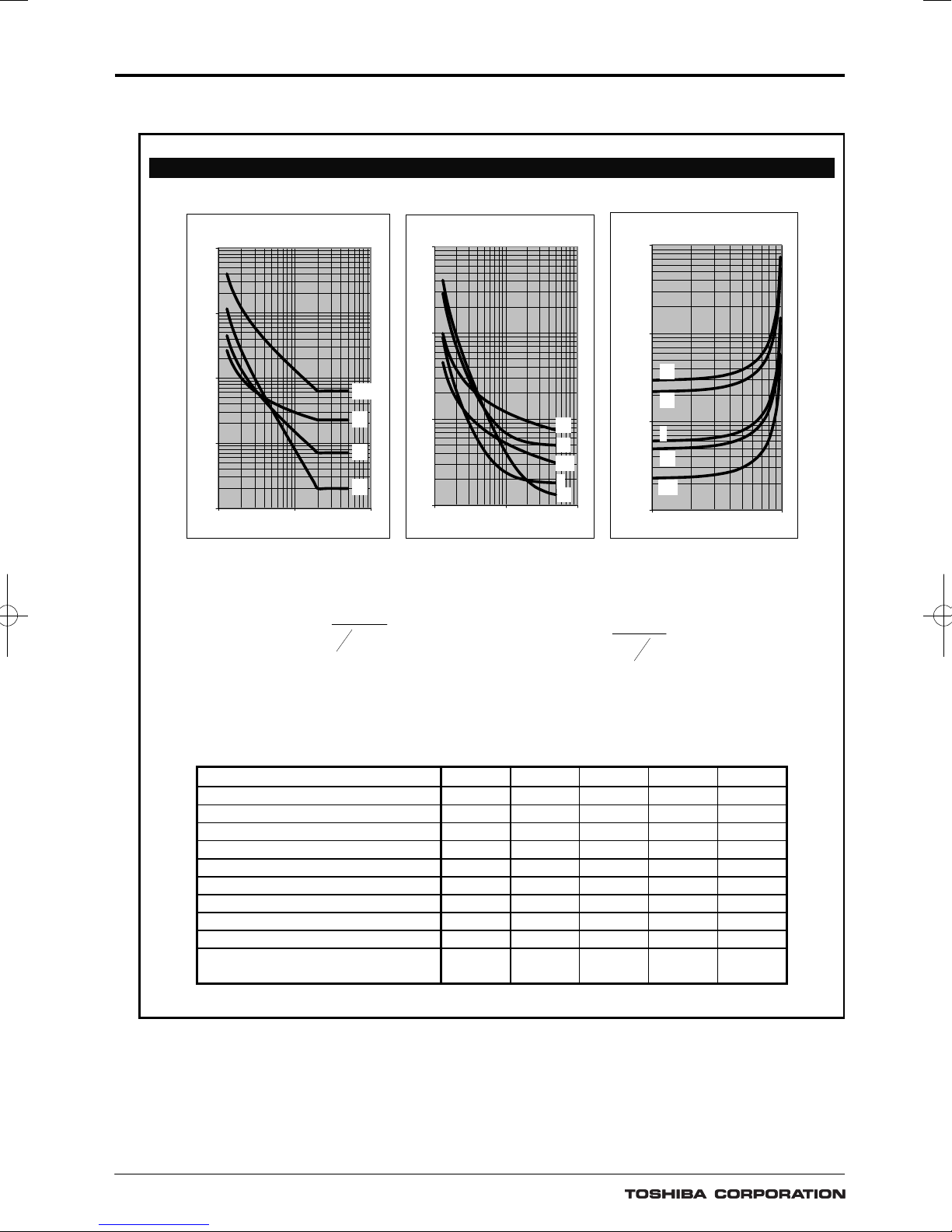
Figure 1 - Operate and Reset Characteristics
Inverse Time Operate and Reset Curves
IEC/UK Inverse Curves
(Time Muliplier TMS = 1)
0.1
1
10
100
1000
1 10 100
Current (Multiple of Setting)
Operating Time (s)
LTI
NI
VI
EI
IEEE/US Inverse Curves
(Time Multiplier TMS = 1)
0.1
1
10
100
1 10 100
Current (Multiple of Setting)
Operating Time (s)
MI
VI
STI
I
EI
IEEE/US Reset Curves
(Time Multiplier T MS = 1)
1.00
10.00
100.00
1000.00
0.1 1
Current (Multiple of S etting)
Time (s)
MI
VI
EI
STI
I
°
¿
°
¾
½
°
¯
°
®
»
»
»
¼
º
«
«
«
¬
ª
u c
Is
I
k
TMSt
1
D
RTMS
Is
I
kr
t
do
u
»
»
»
¼
º
«
«
«
¬
ª
E
1
Inverse time operate function Dependent time reset function
Constants for dependent time curves
Curve Description k
D
C k
r
E
IEC Normal Inverse (NI) 0.14 0.02 0 - IEC Very Inverse (VI) 13.5 1 0 - IEC Extremely Inverse (EI) 80 2 0 - UK Long Time Inverse (LTI) 120 1 0 - IEEE Moderately Inverse (MI) 0.0515 0.02 0.114 4.85 2
IEEE Very Inverse (VI) 19.61 2 0.491 21.6 2
IEEE Extremely Inverse (EI) 28.2 2 0.1217 29.1 2
US CO8 Inverse (I) 5.95 2 0.18 5.95 2
US CO2 Short Time Inverse (STI) 0.02394 0.02 0.01694 2.261 2
User configurable setting 0.00 –
30.000
0.00 –
5.00
0.000 –
5.000
0.000 –
30.000
0.00 –
5.00
 Loading...