

Page 1

G7 Adjustable Speed Drive
Operation Manual
Document Number: 51546-009
Date: March, 2005
Page 2

Introduction
Congratulations on the purchase of the new G7 True To rque Control2 Adjustable Speed Drive (ASD).
The G7 True Torque Control
T orque Contr ol
provide compensation for motor slip, which results in smooth, quick starts and highly efficient operation.
The G7 use s digitally-cont rolled pulse width modula tion. The programmable functions may be accessed
via the easy-to-use menu or via the Direct Access Numbers (see page 59). This feature, combined with
Tos hiba’ s high-performance software, delivers unparalleled motor control and relia bility.
The G7 is a very powerful tool, yet s urprisingl y simple to operat e. The user -fri endly El ectron ic O perator
Interface (EOI) of the G7 has an easy-to-read 240 x 64 pixel graphical LCD screen. The EOI provides
easy access to the many monitoring and programming features of the G7.
The motor control software is menu-driven, which allows for easy access to the motor control parameters
and quick changes when required.
To m aximize the abilities of your new G7, a working familiarity wit h this manual will be required. This
manual has been prepared for the G7 ASD installer, user, and maintenance personnel. This manual may
also be used as a reference guide or for training. With this in mind, use this ma nual to develop a system
familiarity before attempting to install or operate the device.
2
. TIC’s Ve ctor Cont rol Algorit hm enable s the motor t o devel op hig h star ting tor que a nd
2
Adjustable Speed Drive is a solid - sta te AC driv e th at featu r es True
Important Notice
The instructions contained in this manual are not intended to cover all details or variations in equipment
types, nor may it provide for every possible contingency concerning the installation, operation, or
maintenance of this equipment. Should additional information be required contact your Toshiba
representative.
The contents of this ma nual shall not become a part of or modify a ny p rior or existing agreement,
commitment, or relationship. The sales contract contains the entire obligation of Toshiba International
Corporation. The warranty contained in the cont ract between the parties is th e so le warranty of Toshiba
International Corpora tion and an y statement s containe d herein do not creat e new warranties or modify the
existing warranty.
Any electrical or mechanical modifications to this equipment without prior written consent of
Toshiba International Corporation will void all warranties and may void the UL/CUL lis ting or
other safety certifications. Unauthorized modifications may also result in a safety hazard or
equipment damage.
Misuse of this equipment could result in injury and equipment damage. In no event will To shiba
Corporation be responsible or liable for direct, indirect, special, or consequential damage or injury
that may result from the misuse of this equipment.
Page 3

Contacting Toshiba’s Customer Support
Center
Toshiba’s Customer Support Center can be contacted to obtain help in resolving any Adjustable Speed
Drive system problem that you may experience or to provide application information.
The center is open from 8 a.m. to 5 p.m. (CST ), Monday through Friday. The Support Center’s toll free
number is US (800) 231-1412/Fax (713) 466-8773 — Canada (800) 527-1204.
You may also contact Toshiba by writing to:
Toshiba Inter n ational Corporation
13131 West Little York Road
Houston, Texas 77041-9990
Attn: ASD Product Manager.
For further information on Tos hiba’s products and services, please vis it our website at
www.tic.toshiba.com (right click and select Open Weblink in Browser).
TOSHIBA INTERNATIONAL CORPORATION
G7 Adjustable Speed Drive
Please complete the Warranty Card supplied with the ASD and return it to Toshiba by prepaid mail. This will
activate the 12 month warranty from the date of installation; but, shall not exceed 18 months from the shipping
date.
Complete the following information and retain for your records.
Model Number: ______________________________________________________________________
Serial Number:_____ _________________________________________________________________
Project Number (i f applicable):__________________________________________________________
Date of Installation:
Inspected By:______________________________________________________________________
Name of Application:_________________________________________________________________
__________________________________________________________________
Page 4

About This Manual
This manual was written by the To s h iba Technical Public ations Group. This group is tasked with
providing te chnical documentation for the G7 Adjustable Speed Drive. Every effo rt has been made to
provide accurate and concise information to you, our customer .
At Toshiba we’re continuo usly searching for better ways to meet the constantly changing needs of our
customers. Email your comments, questions, or concerns about this publication to
Technical-Publications-Dept@TIC.TOSHIBA.COM.
Manual’s Purpose and Scope
This manual provides information on how to safely install, operate , m aintain, and dispose of your
True Torque Control2 Adjustable Speed Drive. The information provided in this ma nual is
G7
2
applicable to the G7 True Torque Control
This operation manual provides information on the various fea tures and functions of th is powerful costsaving device, including
• Installation,
• System operation,
Adjustable Speed Drive only.
• Configuration and menu options, and
• Mechani cal and electrical specifications.
Included is a section on general safety instruc tions that des cribe the warning labels and symbols t hat are
used throughout the manual. Read the manual completely before installing, operatin g, performing
maintenance , or dis posing of this equip men t.
This manual and the accompanying drawings should be considered a permanent part of the equipment
and should be readily available for reference a nd review. Dimensions shown in the manual are in metric
and/or the English equivalent.
Because of ou r commit ment to c ontinu ous im prov ement, Toshiba International Cor pora tio n reserve s the
right, without prior notice, to update information, make product changes, or to discontinue any product
or service identified in this publication.
Toshiba International Corporation (TIC) shall not be liable for direct, indirect, special, or
consequential damages resulting from the use of the information contained within this manual.
TOSHIBA is a registered trademark of the Toshiba Corporation. All other product or trade re fere nces
appearing in thi s manual are registered trad emarks of their respective owners .
This manual is copy righted. No part of this manual may be photocopied or reproduced in any form
without the prior wr itten consent of Toshiba International Corporation.
© Copyright 2005 Toshiba International Corporation.
All rights reserved.
Printed in the U.S .A.
Page 5

Table of Contents
CE Compliance Requirements ............................................................................................. 10
EMC Installation Guidelines ............................................................................................ 10
Motor C h a ra ct e ri s tics ................. .. ... ....... .. ... .............. ... .. ........ .. .. ............... .. ... ....... ... .. .......... 13
Motor Autotuning ............................................................................................................. 13
Pulse Width Modulation Operat ion ......................... ............................... .................... ......13
Low Speed O p er at i on . ....... .. ... ....... ... .. ............... .. .. ............... .. ... ....... ... .. ............... .. ... ....... 1 3
Overload Protection Adjustment ...................................................................................... 13
Operation Above 60 Hz .................................................................................................... 14
Power F ac to r Co rr ection ..... ... .. ........ .. .. ............... .. ... ....... ... .. ............... .. .. ........ .. ... ............ 14
Light Load Condi tions ............................................ ................... ...................................... 14
Motor/Load Combinations ............................................................................................... 14
Load-p ro d uc e d Neg ative Torque ........ .. ... .............. ... .. ............... .. ... ....... .. ... ............... .. .. ... 15
Motor Braking ..................................................................................................................15
ASD Characteristics .............................................................................................................. 16
Over-current Protection .................................................................................................... 16
ASD Capacity ...................................................................................................................16
Using Vector Contr ol .. ....... .. ... .............. ... .. ........ .. .. ............... .. ... ....... ... .. ............... .. ... ....... 16
Local/Remote Operation .................................................................................................. 16
Instal la t io n a n d Con nectio n s ...... .. ... .............. ... .. ....... ... .. ........ .. .. ............... .. ... ....... ... .. ....... ... 17
Install at i on N ot e s ... .. ............... .. ... ....... .. ... .............. ... .. ........ .. .. ... ....... ... .. ....... ... .. ............... 17
Mounting the ASD ........................................................................................................... 18
Conne ct in g th e A SD ........ .. .. ............... .. ... ....... ... .. ............... .. .. ........ .. ... .............. ... .. ....... ... 19
I/O and Co n tr o l . ............... .. .. ........ .. ... .............. ... .. ....... ... .. ............... .. ... ....... .. ... .............. ... 22
G7 ASD Control ............................................................................................................... 26
Typical Connection Diagram ..................... .......... .................... ........................................30
Comma n d M o d e a nd Freq uency Mo d e C o nt rol ...... ... .. ............... .. ... .............. ... .. ........ .. .. ... 31
Command Control (F003) ................................................................................................31
Frequency Control (F004) ................................................................................................ 32
Override Operation ........................................................................................................... 34
Electronic Operator Interface .............................................................................................. 36
EOI Featu r es ... .. .. ........ .. ... .............. ... .. ....... ... .. ............... .. ... ....... .. ... .............. ... .. ........ .. ..... 36
EOI Oper at io n ......... ... ....... .. ... .............. ... .. ........ .. .. ............... .. ... ....... ... .. ............... .. ... .......37
System Operation .................................................................................................................. 38
Initia l Set u p . ... .. ....... ... .. ....... ... .. ........ .. .. ............... .. ... ....... ... .. ............... .. .. ........ .. ... ............ 38
Opera ti on ( L o ca l) .... ........ .. .. ........ .. ... .............. ... .. ....... ... .. ............... .. ... ....... .. ... .............. ... 38
Default Setting Changes ................................................................................................... 39
Startup Wizar d R equ i rem ents ..... ... .. ............... .. ... .............. ... .. ....... ... .. ............... .. ... ....... .. ... 40
System Configuration and Menu Options ........................................................................... 43
Root Menus ...................................................................................................................... 43
Direct Ac ce ss Pa r am eter Info rmatio n ... ....... ... .. ............... .. ... .............. ... .. ....... ... .. ............... 5 9
Direct Access Parameters/Numbers ................................................................................. 59
G7 ASD Operation Manual i
Page 6

Alarms, Trips, and Troubleshooting .................................................................................. 173
Alarms an d Trips ..... ... ....... .. ... .............. ... .. ........ .. .. ............... .. ... ....... ... .. ............... .. ... ..... 173
Alarms ............................................................................................................................174
User No ti f ic at io n Co d es .. .. .. ........ .. ... ....... .. ... ....... .. ... .............. ... .. ........ .. .. ........ .. ... ....... .. . 176
Trips/Fau lts ..... .. ..... ..... ..... .. ..... ..... ..... .. ..... ..... ..... .. ..... ..... ..... .. ..... ..... .. ..... ..... ..... .. ..... ..... ... 176
Enclosure Dimensions and Conduit Plate Information ................................................... 182
Enclosu r e D imensio n s /Weight ......... .. .. ... ....... ... .. ....... ... .. ............... .. ... ....... .. ... .. ........ .. .. . 182
Conduit Plate Information .......... ........................................................................... .........187
Conduit Extender Box (option) ........... .......... .......... .......... ........... .......... .......... .......... .... 189
EOI Rem o t e M o u nt in g .... .. ....... ... .. ........ .. .. ........ .. ... .............. ... .. ....... ... .. ....... ... .. ............... .. . 190
Current/Voltage Specifications ........................................................................................... 193
Cable/Termin a l Sp ec if i ca t i o ns .... ....... ... .. ....... ... .. ............... .. ... ....... .. ... .............. ... .. ........ .. .. . 195
Dynamic Braking Resistor Wire/Cable Specifications .................................................. 198
Link Rea c t or I nf or mation ..... .. ... ....... ... .. ....... ... .. ............... .. ... ....... .. ... .............. ... .. ........ .. .. . 199
G7 Optional Devices ............................................................................................................ 200
G7 ASD Spare Parts Listing ............................................................................................... 201
ii G7 ASD Operation Manual
Page 7
General Safety Information
DO NOT attempt to install, operate, maintain or dispose of this equipment until you have read and
understood all of the product safety inf ormation and directions tha t are contained in this manua l.
Safety Alert Symbol
The Safety Alert Symbol indicates that a potential personal injury hazard exists. The symbol is
comprised of an equilateral triangle enclosing an exclamation mark.
Signal Words
Listed below are the signal words that are used throughout this manual followed by their descriptions
and associated symbols. When the words DANGER, WARNING and CAUTION are used in th is
manual they will be followed by important safety information that must be carefully adhered to.
The word DANGER pre ce d ed by th e safety al er t symbol in di ca t es th a t an immine nt l y h az ar d o us
situatio n exis ts that, if not avoided, will result in death or seri ous injury to personnel.
DANGER
The word WARNING preceded by the safety alert symbol indicates that a potentially hazardous
situatio n exis ts that, if not avoided, could result in death or serious injury to personnel.
WARNING
The word CAUTION preceded by the safety alert symbol indicates that a potentially hazardous
situation exists which, if not avoided, may result in minor or moderate injury.
CAUTION
The word CAUTION without the safety ale rt symbol indicates a pote ntially hazardous si tuation exists
which, if not avoided, may result in equipment and property damage.
CAUTION
G7 ASD Operation Manual 1
Page 8
Special Symb ols
To identify special hazards, other symbols may appear in conjunction with the DANGER, WARNING
and CAUTION signal words. Thes e symbols indicate areas that require special and/ or strict adherence
to the procedures to prevent serious injury to personnel or death.
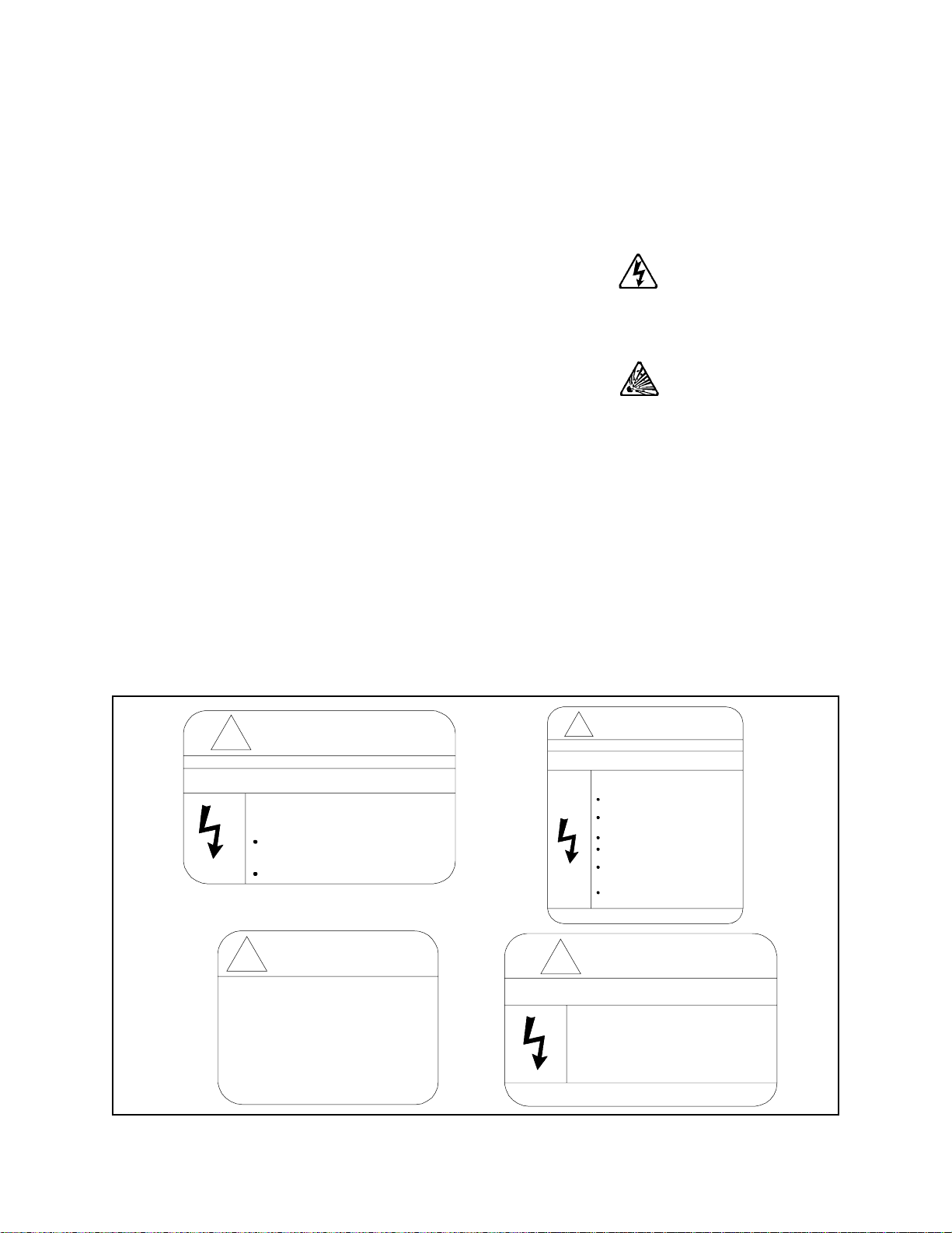
Electrical Hazard Symbol
A symbol which indicates a hazard of injury from electrical
shock or burn. It is comprised of an equilateral triangle
enclosing a lightning bolt.
Explosion Hazard Symbol
A symbol which indicates a hazard of injury from exploding
parts. It is comprised of an equilateral triangle enclosing an
explosion image.
Equipment Warning Labels
DO NOT attempt to insta ll, operate, perform main tenance, or dispose of this equipment until you have
read and understood all of the product labels and us er directions that are contained in this manual.
Shown below are examples of safety labels that may be found attached to the equipment. DO NOT
remove or cover any of the labe ls. If the labels are damaged or if additional labels are required, contact
your Toshiba sales representative for additional labels.
Labels atta ched to the equipment are there to provide useful info rma tion or to indicate an imminently
hazardous s ituation that may result in serious injury, severe property a nd equipment damage, or death if
the inst r uctions are not followed.
Figure 1. Examples of labels that may be found on the equipment.
DANGER
DANGER
!
DO NOT REMOVE, DESTROY, OR COVER THIS LABEL.
READ THE INSTRUCTION MANUAL CAREFULLY BEFORE
ENTERING THIS COMPARTMENT.
HAZARDOUS VOLTAGE Behind These Panels.
Contact With Energized Main Bus Will Cause
Severe Injury, Death, Fire, Explosion, Or
Property Damage.
Turn Off And Lockout Primary And
Control Circuit Power Before Opening
These Panels.
Qualified Operators Only.
CAUTION
!
Excessive Loading of Operating Shaft
Can Prevent Contactor From Closing
Properly Resulting In Major Damage.
Do Not Use Contactor Shaft To Drive
Accessories Such As Mechanical Interlocks
Which Require More Than 5 Kgf-cm Of
Torque To Operate.
DO NOT OPEN THIS DOOR WHILE THE UNIT IS RUNNING.
THIS DOOR IS INTERLOCKED WITH ASD OPERATION.
!
DO NOT REMOVE, DESTROY, OR COVER THIS LABEL.
READ THE INS TRUCTION MANUAL CA RE FULLY BEFORE
INSTALLING, OPERATING, OR SERVICING THIS EQUIPMENT.
HAZARDOUS VOLTAGE
Can Cause Severe Injury, Death, Explosion,
Fire, Or Property Damage.
Only Qualified Personnel Should Be Permitted
To Operarate or Service This Equipment.
Disconnect And Lockout Primary And Control
Circuit Power Before Servicing.
Keep All Panels And Covers Securely In Place.
Never Defeat, Modify, Or Bypass Safety
Interlocks.
Foreign Voltage May Be Present At Interface
Terminals. Isolate Before Performing Service
Or Repairs.
Unauthorized Modifications To This Equipment
Will Void The Warranty.
!
DANGER
HAZARDOUS VOLTAGE MAY BE PRESENT.
Capacitors Are Charged. Wait
At Least 5 Minutes Before Entry.
Check For Charged Voltage
To Dissipate To A Safe Level
Before Opening T he Equipment.
2 G7 ASD Operation Manual
Page 9

Qualified Personnel
Installatio n, ope ratio n, and maint enanc e shal l be perfor med by Qualified Personnel Only. A Qualified
Person is one that has the skills and knowledge relating to the construction, installation, operat ion, and
maintenance of the elec trical equipment and has rece ived safety training on the hazards involved (Refer
to the latest edition of NFPA 70E for additional safety requirements).
Qualified Personnel shall:
• Have carefully rea d the enti re ope ration manual.
• Be familia r with the construction and func tion of the ASD, the equipment being dr iven, and the
hazards involved.
• Able to recognize and properly address hazards associated with the application of motor-driven
equipment.
• Be traine d and au thorized to safely energize, de-energize, ground, lockout/tagout circuits and
equipment, and clear faults in accordance with established safety prac tices.
• Be trained in the proper care and use of protective eq uipment such as safety shoes , rubber gloves,
hard hats, safety glasses, face shields, fl ash clothing, etc., in accord ance with established safety
practices.
• Be trained in rend ering first aid.
For further information on workplace safety visit www.osha.gov.
Equipment Inspection
• Upon receipt of the equipment inspect the packaging and equip me nt for shipping damage.
• Carefully unpack the equipment and check for parts that were damaged during shipping, missing
parts, or conce aled damage. If any discrepa ncies are discovered, it should be noted with t he carrier
prior to accepting the shipment, if possible. File a claim with th e carrier if necessary and
immediately notify your T oshiba sales representative.
• DO NOT install or energize equipment that has been damaged. Damaged equipment may fail
during operation resulting in equipment damage or personal injury.
• Check to see that the rated capacity and the model number specified on the nameplate conform to
the order specifi cations.
• Modification of this equipment is dangerous and must not be performed except by factory trained
representat ives. When modifications are re quired contact your Toshiba sales representative .
• Inspections may be required before and after moving installed equipment.
• Keep the equ ipm ent in an upright position.
• Contact your Toshiba sales representative to report discrepancies or for assistance if required.
G7 ASD Operation Manual 3
Page 10

Handling and Storage
• Use prope r lifting techniques when movi ng the ASD; including properly sizing up the l oad, getting
assistance, an d usi ng a forklift if required.
• Sto re in a well-ventilated covere d lo cation an d p r eferably in the original ca r ton if the equip me n t
will not be used upon receipt.
• Store in a cool, clean, and dry location. Avoid storage locations with extreme temperatures, rapid
temperature ch anges, high humidity, moisture, dust, corrosive gases, or metal particle s.
• The storage temperature range of the G7 ASD is 14° to 104° F (-10 to 40° C) .
• Do not store the unit in pl aces tha t are e xposed to outside we ather c onditi ons (i. e., wi nd, rain , snow,
etc.).
• Store in an upright position.
Disposal
Never dispose of electrical components via incineration. Contact your state environmental agency for
details on disposal of electrical components and packaging in your area.
Installation Precautions
Location and Ambient Requirements
• The Toshiba ASD is intended for permanent installations only .
• Installation should conform to the 2002 National Electrical Cod e — Articl e 110 (NEC)
(Requirements For Electrical In stallati ons), al l regulations of the Occupational Safety and
Health Administration, and any other applicable na tional, regional , or industry codes and
standards.
• Select a mounting location that is easily accessible, has adequate personnel working space, and
adequate il lum ination for adjustment, inspection, and maintenance of the equipm ent (refer to 2002
NEC Article 110-13).
• A noncombustible insulati ng floor or mat should be provided in the area immediately surrou nding
the electrical system.
• Do Not mount the ASD in a location that would produce catastrophic results if it were to fall from
its mounting loca tion (equipment damage or injury).
• Do Not mount the ASD in a locati on that would allow it to be exposed to flammable chemicals or
gases, water, solvents, or other fluids.
• Avoid installation in areas where vibration, heat, humidity, dust, fibers, steel particles, explosive/
corrosive mists or gases, or sources of electrical noise are present.
• The installation location shall not be exposed to direct sunlight.
• Allow proper cl earance spaces for installation. Do not obstruct the ventilation openings. Refe r to
the section titled
requirements.
Installation and Connections on pg. 17 for further information on ventilation
• The ambient operating temperature range of the G7 ASD is 14° to 104° F (-10 to 40° C).
• See th e sec ti on titl ed I nst alla tion an d Conne ctio ns on pg. 17 for a dditio nal informati on on i nsta lling
the drive.
4 G7 ASD Operation Manual
Page 11

Mounting Requirements
• Only Qualified Personnel should install this equipment.
• Install the unit in a secure and upright position in a well-ventilated area.
• A noncombustible insulati ng floor or mat should be provided in the area immediately surrou nding
the electrical system at th e place where maintenance operations are to be perfo r med.
• As a minimum, the installation of the equipment should conform to the NEC Article 110
Requirements F or Ele ctric al Ins tal latio ns , OSHA, as we ll as any o the r appli cable nati ona l, reg ional,
or industry codes and standards.
• Installation practices should conform to the late s t revision of NFPA 70E Electrical Safety
Requirements for Employee Workplaces.
• It is the responsibility of the pers on ins talling the ASD or the electrical maintenance personnel to
ensure that the unit is installed in to an e nclosure that will protect personnel against electric shock.
Conductor Routing and Grounding
WARNING
• Use sepa rate me tal c ondui ts fo r rout ing the i nput power, output power, and c ont rol cir cui ts and e ach
shall have its own ground cable.
• A separate ground cable should be run inside the conduit with the input power, outpu t power, and
and control circuit s.
• DO NOT connect control terminal strip return marked CC to earth ground.
• Always ground the unit to prevent elec trical shock and to help reduce electrical nois e.
• It is the responsibility of the pers on ins talling the ASD or the electrical maintenance personnel to
provide proper grounding and branch circuit protection in accordance with the 2002 NEC and any
applicable local codes.
The Metal Of Conduit Is Not An Acceptable Ground.
Power Connections
DANGER
Contact With Energized Wiring Will Cause Severe Injury Or Death.
• Turn off, lockout , an d tagout all power sources before proceeding to connect th e power wiring to
the equ ip ment.
• After ensuring that all power sources are turned off and isolated in accordance with established
lockout/ta gout procedures, connect thre e-phase power source wiring of the corre ct voltage to the
correct input terminals and connect the output terminals to a motor of the corr ec t voltage and type
for the application (refer to NEC Article 300 – Wiring Methods and Article 310 – Conductors For
General Wiring). Size the branch circuit conductors in accordance with NEC Table 310.16.
• If multip le condu ctors that are small er than t he recommende d siz es are used in par allel for th e in put
or output powe r, each branch of the parallel set shall have its own conduit and not share its c onduit
with other parallel sets (i.e., place U1, V1, and W1 in one conduit and U2, V2, and W2 in anoth er)
(refer to NEC Article 300. 20 and Article 310.4). National and local electrical codes should be
G7 ASD Operation Manual 5
Page 12

referenced if three or more power conduc tors are run in the same conduit (refer to 2002 NEC
Article 310 adjustment factors on page 70-142).
• Ensure that the 3-phase input power is Not connect ed to the output of the ASD. This will dama ge
the ASD and may cause injury to personnel.
• Do not insta ll the ASD if it is damaged or if it is missing any component(s).
• Do Not connect resistors ac ross terminals PA – PC or PO – PC. This may cause a fire.
• Ensure the correct phase sequence and the desi red direction of motor rotation in the Bypass mode
(if applicable).
• Turn the power on only after attaching and/or securing the front cover.
Protection
• Ensure that primary protect ion exis ts for the input wiring to the equipm ent. This protect ion must be
able to interru pt the available fault current from the power line. The equipme nt may or ma y not be
equipped with an in put disconnect (opti on).
• All cable entry openings must be sealed to reduce the risk of entry by vermin and to allow for
maximum cooling efficiency.
• Follow all warnings and precautions and do not exceed equipment ratings.
• If using multiple motors provide separate overload protection for each motor and use V/f control.
• External dynamic braking resistors must be thermally prot ec ted.
• It is the responsibility of the pers on ins talling the ASD or the electrical maintenance personnel to
setup the Emergency Off brak ing syste m of the ASD. The function of the Emergency Off braking
function is to remove output power from the drive in the eve nt of an emergency. A supplemental
braking system may also be engaged in the event of an emergency. For further information on
braking systems, see
Enable on pg. 112.
Note: A supplemental emergency stopping system should be used with the ASD. Emergency
stopping shou ld not be a task of the ASD alone.
• Follow all warnings and precautions and do not exceed equipment ratings.
DC Injection Brak ing Start Frequency on pg. 105 and Dynamic Braking
6 G7 ASD Operation Manual
Page 13

Syste m In teg r at ion Precau tions
The following preca utions are provided as general guidelines for the setup of the ASD withi n the
system.
• The Toshiba ASD is a general-purpose product. It is a system component only and the syste m
design should take this into consideration. Please contact your Toshiba sales representat ive for
application-specific information or for training support.
• The Toshiba ASD is part of a larger system and the safe operation of the ASD will depend on
observing certain precautions and performing proper system integr ation.
• A detailed system analysis and job safety ana lysis should be performed by the s ys tems designer
and/or syste ms inte grator be fore the i nstal lati on of t he ASD com ponent. Con tact your Toshiba sales
representat ive for options availability and for application-spe cific system integration information if
required.
Personnel Protection
• Instal lation, operation, and maintenance shall be performed by Qualified Personnel Only.
• A thorough understanding of the ASD will be required before the installation, operation, or
maintenance of the ASD.
WARNING
• Rotating machinery and live con ductors can be hazardous and shall not come into contact with
humans. Personnel should be protected from all rotating machinery and electrical hazards at all
times.
• Insulat ors , machine guards, and electrical safeguards may fail or be defeated by the purposeful or
inadvertent actions of workers. Insulators, machine guards, and electrical safeguards are to be
inspected (and tested where possible ) at installation and pe riodically after installation for potential
hazardous conditions.
• Do not allow personnel near rotating machinery. Warning signs to this effect shall be posted at or
near the machinery.
• Do not all ow pe rsonne l near e lectr ical conduc tors. Human cont act wi th e lect rical conduct ors c an be
fatal. Warning signs to this effec t shall be posted at or near the hazard.
• Personal protection equip ment shall be provided and used to pr otect employees from any hazards
inherent to system operation.
• Follow all warnings and precautions and do not exceed equipment ratings.
System Setup Requirements
• When using the ASD as an integral part of a larger system, it is the responsibility of the ASD
installer or maintenance per sonnel t o en sure that th ere is a fail-safe in place, i.e., an arrangement
designed to switch the system to a safe condition if there is a fault or failure.
• System safety features should be employed and designed into the int egrated system in a manner
such that s ys te m op e r at io n , ev en in th e ev e nt of sy s te m fa i lu r e, wi ll no t cau s e h arm o r res ul t in
personnel injury or system damage (i.e., E-Off, Auto-Restart settings, System Interloc ks, etc.).
• The programming s etup and system configuration of the ASD may allow it to start the motor
unexpectedly. A familiarity with the Auto-r estart settings are a requi rem ent to use this product.
G7 ASD Operation Manual 7
Page 14

• Improperl y desig ned or impr operly inst al led syst em interl ocks may ren der the m otor unabl e to sta rt
or stop on command.
• The failure of external or ancillary components may cause intermittent system operation, i.e., the
system may sta rt the motor without warning.
• There may be thermal or physical properties, or ancillary dev ices integrated into the overall system
that may allow for the ASD to start the motor without warning. Signs at the equipment installation
must be posted to this effect.
• If a secondary magnetic contactor (MC) is used between the ASD and the load, it should be
interlocke d to halt the ASD before the secondary cont act opens. If the output contactor is used for
bypass operati on, it must be interlocked such that commercial power is never applie d to the ASD
output terminals (U, V, W).
• Power factor improvement capacitors or surge absorbers must not be installed on the output of the
ASD.
• Use of the built-in system protective features is highly recommended (i.e ., E-Off, Overload
Protection, etc.).
• The operating controls and system status indicators should be clearly readable and positioned
where the operator can se e the m wit hout obstruction.
• Additi onal warnings and notifications shall be poste d at the equipment installation locatio n as
deemed required by Qualified Personnel.
• Follow all warnings and precautions and do not exceed equipment ratings.
Operati ona l an d M ain te na nc e Prec au tio ns
WARNING
• Turn off, lockout , and tagout the main power, the control power, and instrumentation connections
before inspecti ng or servicing the drive, or ope ning the door of the enclosure.
• Turn off, lockout , and tagout the main power, the control power, and instrumentation connections
before proceeding to disconnect or connect the power wiring to the equipment.
• The capac itors of t he ASD mai ntain a resi dual c harge for a pe riod of time after turn ing the ASD off .
The required time for each ASD typeform is indicated with a cabinet la bel and a Charge LED.
Wait for at least the minimum time indicated on the enclosure-m ounted label and ensure that the
Charge LED has gone out before opening the door of the ASD once the ASD power has been
turned of f.
• Turn the power on only after attaching (or closing) the front cover and Do Not remove the front
cover of the ASD when the power is on.
• Do Not attempt to disassemble, modify, or repair the ASD. Call your Toshiba sales representative
for repair information.
• Do not place any objects inside of the ASD.
• If the ASD should emit smoke or an unusual odor or sound, turn the power of f im me diately.
• The heat si nk and other components may become ext remel y hot to the t ouch. All ow the unit to cool
before coming in contact with these items.
• Remove power from the ASD during extended periods of non-use.
• The system should be inspected periodically for damaged or improperly functioning parts,
cleanliness, and to ensure that the connectors are tightened securely.
8 G7 ASD Operation Manual
Page 15

• Ensure that the Run functions (F, R, Preset Speed, etc.) of the ASD are off before performing a
Reset. The post-rese t settings may allow th e ASD to sta rt unexpectedly.
• Retry or Reset settings may allow the motor to start unex pectedly. Warnings to this ef fect should
be clearly poste d near the ASD and motor.
• In the event of a power failure, the motor may restart after power is restored.
• Follow all warnings and precautions and do not exceed equipment ratings.
DO NOT install, operate, perform maintenance, or dispose of this equipm ent until you have read and
understood all of the product warnings and user direc tions. Failure to do so may result in equipment
damage, operator injury, or loss of life.
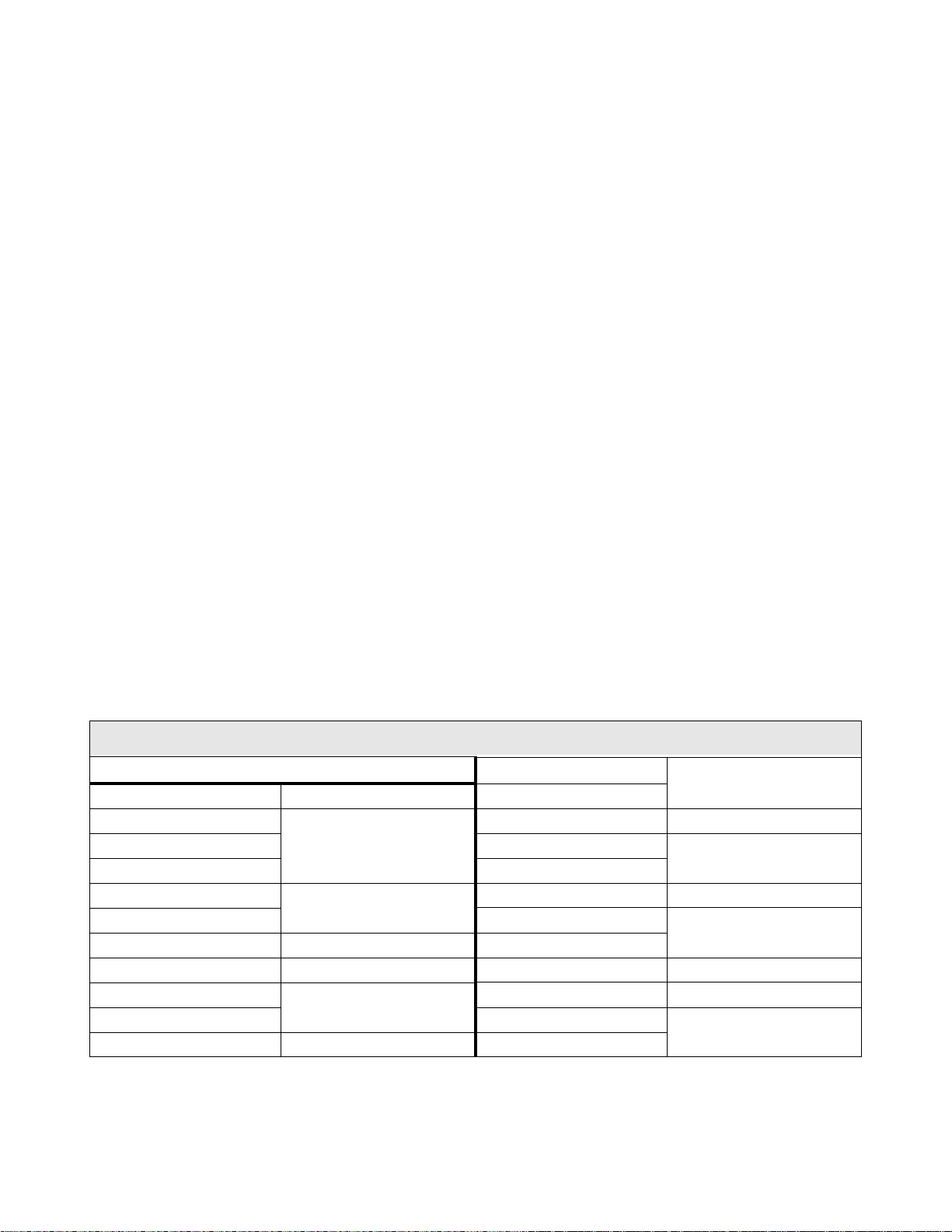
Service Life Information
Part Name Service Life Remarks
Large Capacity Electrolytic
Capacitor
Cooling Fan 26,00 0 H o urs
CN Connectors 100 Connec ts/Disconnects
On-board Relays 500,000 Actuations
5 Years
When not used for long periods,
charge semi-annually.
G7 ASD Operation Manual 9
Page 16

CE Compliance Requirements
In addition to the local and regional safety re quirements, this section describes additional criteria that
must be met to qualify for European Confor mity (CE) certification. All relevant apparatus placed on
the European market is required to comply to the European Community directive on electromagnetic
compatibility (EMC). The following instructions provide a means of compliance for the 7-series of
ASDs. A Technical Const ruct ion File (TFC ) indica tes the rationa le used to de clare compl iance an d is on
file at Toshiba Inter national Corporation, Houston, Texas U.S.A.
EMC Installation Guidelines
All systems placed on the Europ ean market ar e required to comply wi th th e Europea n Co mm u n ity
directive regarding electromagnet compatibility (EMC). Toshiba ensures that all systems deployed in
the European market ha ve be en s cre ened and are in 100% compliance with the following standards:
• Radiated Interference: EN 55011 Group 1 Class A
• Mains Interference: EN 55011 Group 1 Cla ss A
• Radiate d S usceptibility: IEC 801-3 1984
• Conducted RFI Susceptibility: prEN55101-4 (prIEC801-6) Doc 90/30270
• Electrostatic Dischar ge: IEC801-2 1991
• Electrical Fast Transient: IEC 801-4 1988
• Surge : IEC1000-4-5 1995 2 KV line-to-line, 4 KV line-to-earth
• Voltage Interruption: IEC 1000-4-11
General EMC Guidelines for Consideration
• Input filters of the appropriate rating shall be used.
• Proper grounding is a requirement.
• Grounds shall be kept to the minimum length to accomplish the connection.
• Grounds shall have low RF impedance.
• A central ground shall employed in a complex system.
• Paint or corrosion can hamper good grounding; remove as required.
• Keep control and power cabling separated. Minimize exposed (unsc reened) cable.
• Use 3600 screened connections where possible.
CE Compliant Installation Guidelines
ASDs should be instal led in accordance with the following guidelines.
1. Filtering — An input f ilter sh al l be us ed with the ASD. A S chaf f ner F N258 seri es in put f ilt er of th e
appropriate rating shall be mounted next to the ASD.
2. Mechanical — The ASD and the associated equipment shall be mounted on a flat metallic
backplane. A minimum space of 5 cm (2 inches) shall be between the ASD and the filter to allow
for ventilation. The filter output cable is to be connected from the bottom of the filter to the ASD
power input and is to be the minimum lengt h required for a connection. See
filter selection assistance.
Table 1 on page 11 for
10 G7 ASD Operation Manual
Page 17
Units received as an Open Chassis shall not be placed into operation until being placed into an
approved enclosure that will protect personnel against electrical shock.
Opening and closing of enclosures or barriers should be possible only with th e us e of a key or a
tool.
3. Cabling — The power, filter, and motor cables shall be of the appropriate current rating. The
cables shall be connected in accor dance with the guidelines of the manufacturer and the applicable
local and national agencies. A 4-core screened cable (such as RS 379-384) is to be used for the
power and earth connections to minimize RF emissions. Control cabling must be screened using
P/N RS 367-347 or a similar component.
4. Grounding — The mains (input) ground shall be conne cted at the grou nd ter minal provide d on the
filter. The filter and motor shall be grounded at the ground terminals provided in the ASD.
5. Screening — The mains (input) screen is to be conne cted to the metallic back-plane at the filter;
remove any finish coating as required. The screen over the filter output cables, the motor cable
screen, and the control wire screens must be connected to the ASD case using glands or conduit
connectors. The motor ca ble screen shall be connect ed to the motor case. When using a braking
resistor, the cabling between the resistor and ASD shall also be screened. This screen shall connect
to both the ASD enclo sure and the resistor enclosure.
6. Where residual-current-operated pr otective device (R CD) is used for protection in case of direct or
indirect contact, only RCD of type B is allowed on the supply side of this Ele ctronic Equipment
(EE). Otherwise, a noth er protecti ve meas ure shall be appli ed, such as s eparati on of the EE from the
environment by double or feinforced insulat ion, or isolation of the EE and the supply system by a
transformer.
See the G7 Filter Selection below for the recommended input filters for a given typeform.
Table 1.
G7 Filter Selection Table
230V VT130G7U4110B
VT130G7U2010B FN258-7 VT130G7U4160B
VT130G7U2015B
VT130G7U2025B VT130G7U4270B
VT130G7U2035B VT130G7U4330B
VT130G7U2055B
VT130G7U2080B VT130G7U4500B
VT130G7U2110B FN258-42 VT130G7U4600B
VT130G7U2160B FN258-75 VT130G7U4750B FN258-130
VT130G7U2220B
VT130G7U2270B VT130G7U412KB
VT130G7U2330B FN258-130 VT130G7U415KB
FN258-16
FN258-30
FN258-100
VT130G7U4220B FN258-42
VT130G7U4400B FN258-75
VT130G7U410KB FN258-180
FN258-30
FN258-55
FN258-100
FS5236-300
G7 ASD Operation Manual 11
Page 18
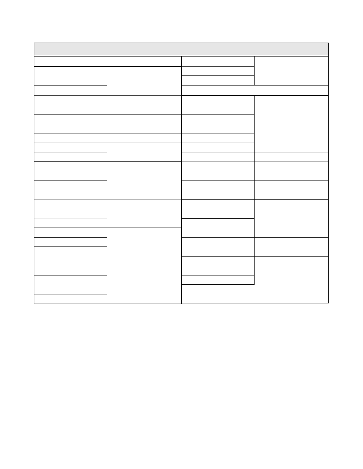
G7 Filter Selection Table
460V
VT130G7U4015B
VT130G7U4025B VT130G7U430KB
VT130G7U4035B 600V
VT130G7U4055B
VT130G7U4110B
VT130G7U4160B VT130G7U6055B
VT130G7U4270B
VT130G7U4330B VT130G7U6160B FN258-30
VT130G7U4400B FN258-75 VT130G7U6220B
VT130G7U4500B
VT130G7U4600B VT130G7U6330B
VT130G7U4750B FN258-130 VT130G7U6400B
VT130G7U410KB FN258-180 VT130G7U6500B FN258-75
VT130G7U412KB
VT130G7U415KB VT130G7U6750B
VT130G7U420KB
VT130G7U425KB VT130G7U612KB
VT130G7U430KB VT130G7U615KB
VT130G7U4015B
VT130G7U4025B VT130G7U625KB
VT130G7U4035B VT130G7U630KB
VT130G7U4055B
VT130G7U4080B
FN258-7
FN258-16
FN258-30
FN258-55
FN258-100
FS5236-300
FS5236-500
FN258-7
FN258-16
VT130G7U420KB
VT130G7U425KB
VT130G7U6015B
VT130G7U6035B
VT130G7U6110B
VT130G7U6270B
VT130G7U6600B
VT130G7U610KB FN258-130
VT130G7U620KB FS5236-300
FS5236-500
FN258-7VT130G7U4080B VT130G7U6025B
FN258-16VT130G7U4220B FN258-42 VT130G7U6080B
FN258-42
FN258-55
FN258-100
FS5236-180
FS5236-500
12 G7 ASD Operation Manual
Page 19

Motor Characteristics
Listed below are some variable speed AC motor control concepts with which the user of the
G7 Adjustable Speed Drive should become familiar.
Motor Autotuning
Motor production methods may cause minor differences in the motor operation. The negative effects of
these diffe r ences may be minimized by using the Autotune feature of the G7 ASD. Autotuning is a
function of the G7 that measures several para meters of the c onnected motor and places these readings in a
stored table. The software uses the informatio n in the table to help optimize the response of the ASD to
application-specific load and operational requirements. The Autotuning function may be enabled for
automatic tuning , co nfigured manually at
The measured parameters include the rotor resistance, the stator resistance, the required excitation
inductance, rotational inertia values, and leakage inductance values.
The G7 ASD is also equipped with a factory-loaded table of motor parameters that fit several different
types of motors. To use this function, disable Autotune and sel ect a motor type at
Pulse Width Modula tio n Op e ration
F400, or disabled.
F413.
The G7 ASD uses a sinusoi d al Pulse Width Modulation (PWM) control system. The output current
waveform generated by the ASD approaches that of a perfect sine wave; however, the output wavefo rm is
slightly distorted. For this reason, the motor may produce more heat, noise, and vibration when operated
by an ASD, rather than directly from commercial power.
Low Sp eed Operatio n
Operating a general-purpose motor at lower speeds may cause a decrease in the cooling ability of the
motor. Reducing the torque requ irement of the motor at lower speeds will decrease the generated heat at
lower speeds.
When the motor is to be operated at low spee d (less than 50% of full speed) and at the rated torque
continuously, a Tos hiba VF motor (designed for use in conjunction with an ASD) is recommended. When
the ASD is used with a VF motor, the VF Motor overload protection set ting must be enabled (see
Program ⇒ Protection Parameters ⇒ Overload ⇒
V/f Motor Enable/Disable).
Overload Protection Adjustment
The G7 ASD software monitors the output current of the sys tem and determines when an overload
condition occurs. The overload current level is a percentage of the rating of the motor. This function
protects the motor from overload.
The default setting for the overload detection circuit is set to the maximum rated current of the ASD at the
factory. This set ting will have to be adjusted to match the rating of the motor with which the ASD is to be
used. To change the overload reference level, see
G7 ASD Operation Manual 13
Electro ni c Thermal Protection #1 on pg. 154.
Page 20

Operation Above 60 Hz
A motor produces more noise and vibration when it is operate d at frequencies above 60 Hz. Also, when
operating a motor a bove 60 Hz, th e rated lim it of the motor or its bear ings m ay be ex ceeded; t his may void
the motor warranty.
Contact the motor manufacturer for additional information before operating the motor above 60 Hz.
Power Factor Correction
DO NOT connect a power factor correction capacitor or surge absorber to the output of the ASD.
If the ASD is used with a motor that is equipped with a capacitor for power factor correction, remove the
capacitor from the motor.
Connecting eit her of these devices to the output of the ASD may cause the ASD to malfunction and trip,
or the output device may cause an over-current condition resulting in damage to the device or the ASD.
Light Load Conditions
When a motor is operated under a co ntinuous light load (i. e., at a load of less than 50% of its rated
capacity) or it drives a load which produces a very small amount of inertia, it may become unstable and
produce abnormal vibration or trips because of an over-current condition. In such a case, the carrier
frequency may be lowered to compensate for this undesirabl e condition (see Program ⇒ Special Control
Parameters ⇒
Carrier Frequency).
Note: For proper operation, the carrier freq uency must be 2.2 kHz or above except when
operating in the Constant Torque, Variable Torque , or the 5-Point Setting modes.
Motor/Load Combinations
When the ASD is used in comb ination with one of the following motors or loads, it may result in unstable
operation.
• A motor with a rated capacity that exceeds the motor capacity recommended for the ASD.
• An explosion-proof motor.
When using the ASD with an explosion-proof motor or other special motor types, lower the carrier
frequency to s tabilize the o per ation. DO NOT set the carrier frequency below 2.2 kHz if operati ng the
system in the vector control mode.
Note: For proper operation, the carrier freq uency must be 2.2 kHz or above except when
operating in the Constant Torque, Variable Torque , or the 5-Point Setting modes.
• If the motor that is coupled to a load that has a large backlash or a reciprocating load, use one of the
following procedures to stabilize its operation.
• Adjust the S-pattern acceleration/deceleration setting,
• If in the Vector control mode, adjust th e response time, or
• Switch to the Constant Torque control m ode.
14 G7 ASD Operation Manual
Page 21

Load-pro du ce d Nega tiv e Torque
When the ASD is used with a load that produces negative torque (an ove rhauling load), the over-voltage
or over-current protective functions of the ASD may cause nuisance trippin g.
To m inimize the undesirable effects of negative torque the dynamic braking system may be used. The
dynamic braking syste m converts the regenerate d ene rgy into heat that is dissipated using a braking
resistor. The braking resistor must be suitably matched to the load. Dynamic braking is also effective in
reducing the DC bus voltage during a momentary over-voltage conditi on.
CAUTION
If under extreme conditions the dynamic braking syste m or a compo nent of this system were to fail, the
dynamic braking resistor may experience an extended over-current condition. The DBR circuit was
designed to dissipate excessive amounts of heat and if the extended over-current condition were allowed
to exceed the circuit param eters, this condition could result in a fire hazard.
To c ombat this c onditi on, the 3-pha se in put may be connect ed usi ng conta ctors that a re confi gure d to open
in the event of an extende d DBR over-current condit ion or an internal circuit failure. Using a thermal
sensor and/or overload protection as the 3-phase input contactor drive signal, the contactors will open and
remove the 3-phase input power in the event of an extended DBR over-c urrent or system over-voltage
condition.
Motor Braking
The motor may continue to rotat e and c oast t o a sto p after being shu t off due to t he inert ia of the load. If an
immediate stop is required, a braking system should be used. The two most common types of motor
braking systems used with the G7 ASD are DC Injection Braking and Dynamic Braking.
For further information on braking systems, see DC Injection Braking on pg. 105 and Dynamic
Braking Enable on pg. 112.
G7 ASD Operation Manual 15
Page 22

ASD Characteristics
Over- current Protection
Each G7 ASD model was designed for a specified operating power range. The ASD will incur a trip if the
design specifications are exceeded.
However, the ASD may be operated at 110% of the specified output-curre nt range continuously or at
150% for a limited amount of time as indicated in the sect ion titled
193. Also, the Overcurrent Stall Level may be ad justed to help with nuisan ce over-current trips (se e
F601).
When using the ASD fo r an application th at controls a motor which is rated signi f icantly less th an the
maximum current rating of the ASD, the over-current limit (Thermal Overload Protection) setting will
have to be changed to match th e application. For furth er information on this parame ter, see
Thermal Protection #1 on pg. 154.
ASD Capacity
The G7 ASD must not be us ed wi t h a mo to r th at ha s a sig n if i cantly la rger capacit y, even if th e mo tor is
operated under a small load. An ASD being used in this way will be susceptible to a high-output peak
current which may result in nuisance tripping.
Current/Voltage Specifications on pg.
Electronic
Do not apply a level of input voltage to an ASD that is beyond that which the ASD is rated. The input
voltage may be stepped down when requ ired with the use of a step-down transform er or some other type
of voltage-reduction system.
Using Vector Control
Using Vector Control enables the system to produce very high torque over the entire ope rating range
even at ex t r emely low sp ee ds. Vector Control may be used with or without feedback. However, using
feedba ck increases the speed accuracy for applications requiring precise speed control. En ab ling the
Automatic Energy Savings fur ther increases the efficiency o f the G7 ASD while maintaining its robust
performance.
Vector Control is not capable of operating multiple motors connec ted in parallel.
See F015 on pg. 64 for further information on using Vector Co ntr ol.
Local/Remote Operation
While running in th e Local mode at a non-zer o speed, if the RJ45 conne ctor is remove d from the EOI and
then reinserted, the ASD remains in the Local mode even though the Local LED is of f (press Run to
illuminate the Local LED). The ASD output remains at the frequency of the F requency Command field
at the time of the disconnect so long as the connect or is disconnected.
Once reinserted, the reference fre quency that was loaded into the EEPROM (not RAM) before the
disconnect will be the fre quency to which the ASD output will return.
To prevent this condition, before disconnecting the RJ45 connector ensure that the ASD is off.
16 G7 ASD Operation Manual
Page 23

Installation and Connections
The G7 Tr ue Torque Control2 Adjustable Speed Drive may be set up initially by performing a few
simple config uration sett ings. To operate properly , the ASD mus t be secu rely mo unted an d connec ted to
a power source (3-phase AC input at the L1/R, L2/S, and L3/T terminals). The control terminals of the
ASD may be used by connecting the terminals of the Control Terminal Strip to the proper sensors or
signal input sources (see the section titled
Note: The optional ASD-Multicom boards may be used to e xpand the I/O functionality of
the ASD. See the section titled
information on the available options.
The output terminals of the ASD (T1/U, T2/V, and T3/W) must be connected to the motor that is to be
controlled (see
As a minimum, the installation of the ASD shall conform to Article 110 of the 2002 NEC, the
Occupational Safety and Health Administration requirements, and to any other loca l and regional
industry code s a nd st andards.
Upon initial syst em powerup, the Startup Wizard starts automatically. The Startup Wizard assists the
user with the initial configuration of the G7 True Torque Control
section titled
Figure 18 on pg. 30).
Initial Setup on pg. 38 for additional information on the Startup Wizard.
Installation Notes
I/O and Control on pg. 22).
G7 Optional Devices on pg. 200 for further
2
Adjustable Speed Drive. See the
When a brake-equip p ed motor is con n ected to the A SD, it is possib le that the brake may not release at
startup be cause of i nsuf f icie nt vo ltage . To avoid this, Do Not co nnec t t he b rake or t he bra ke cont ac to r to
the output of the ASD.
If an output cont actor i s used for byp ass opera tion, it mus t be int erlock ed such tha t commer cial po wer is
never applied to the output terminals of the ASD (T1/U, T2/V, or T3/W).
If a secondary magnetic contact or (MC ) is used between the output of the ASD and the motor, it s hould
be interlocked such that the ST – CC connecti on is disconnected befor e the output contactor is ope ned.
Do Not open and then close a seco ndary magnetic contactor between the ASD and the moto r unless the
ASD is off and the motor is not rotating.
Note: Re-applicat ion of power via a secondary co ntact while the ASD is on or while the
motor is s t il l turni n g m a y ca u s e ASD dam a g e .
On some devices the ST-to-CC connection is further enhanced by the operation of the MS1 AUX relay
circuit. The MS1 AUX relay circuit is normal ly open and closes the ST-to-CC connection (via ST1)
only after norma l system power is available. The MS1 AUX relay circuit prohibits the ST-to-CC
connection in the event that the MS1 contactor fail s to close during start up or if MS1 open s while the
ASD is running. For the 230 volt ASD this feature is available on the 30 HP system, on the 460 volt
ASD this feature is available on the 75 HP and above systems, and on the 600 volt ASD it is availabl e
on the 60 HP and above systems.
Figure 2. ST activation using the MS1 AUX circuit configuration.
G7 ASD Operation Manual 17
Page 24
The ASD input voltage should remain within 10% of the specified input voltage ra nge. Input voltages
Figure 3. Circuit breaker configuration.
approaching the upper or lower limit setti ngs may require that the overvoltage and undervoltage stall
protection level parameters,
should be avoided.
The frequency of the inp ut power should be ±2 Hz of the specifi ed input frequency.
Do not use an ASD with a motor t hat has a power rating that is higher than the rated output of the ASD.
The ASD is designed to operate NEMA B motors. Consult with your sales repr esentative before using
the ASD for special applica tions such as with an explosion-proof motor or applications with a piston
load.
Do Not apply commercial power to the output terminals T1/U, T2/V, or T3/W.
Disconnect the ASD from the motor before megging or applying a bypas s vol tage to the motor.
Interface problems may occur when an ASD is used in conjunction with some types of process
controllers. Signal isolation may be req uired to prevent controller and/or ASD malfunction (contact
your Toshiba sales repres entative or the process control ler manufacturer for additiona l information
about compatibility and signal isolation).
Use caution when setting the output frequency. Over speeding a motor decrea se s its ability to deliver
torque and may result in da ma ge to the motor and/or the driven equipment.
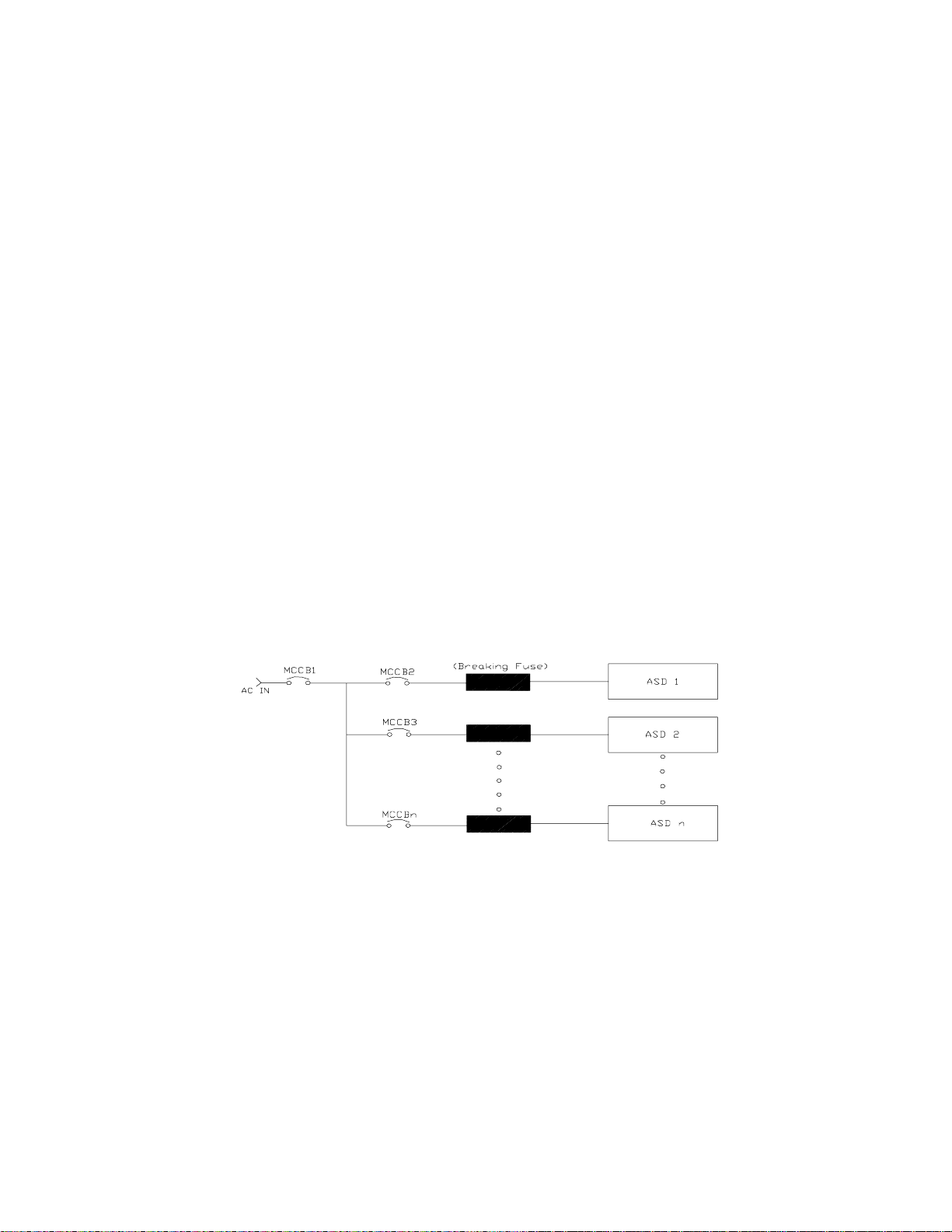
All G7 AS Ds are equipped with internal DC bus fuses. However, not all G7 ASDs are equipped with
internal primary power input fuses (HP dependent). When connecting two or more drives that have no
internal fuse to the same power line as shown in
breaking configuration that will ensure that if a short circuit occurs in ASD 1, only MCCB2 trips, not
MCCB1. If it is not feasible to use this configuration, insert a fuse between MCCB2 and ASD 1.
F626 and F629, be adjusted. Voltages outside of the permissible tolerance
Figure 3, it will be necessary to select a ci rcuit-
Mounting the ASD
Install the unit securely in a well venti lated area that is out of direct sunlight using the mounting holes
18 G7 ASD Operation Manual
on the rear of the ASD.
The ambient temperature rating for the G7 ASD is from 14 to 104° F (-10 to 40° C). The process of
converting AC to DC, and then back to AC produces heat. During normal ASD operation, up to 5% of
the inp u t energy to the ASD may be dissipated as heat. If in stalling the ASD in a cabinet, ensure that
there is adequate ventilation.
Do Not operate the ASD with the enclosure door open.
CAUTION
Page 25

When ins t alling mu ltiple ASDs, ensure th at there is a clearance space of at l east 8 inches (20 cm) from
the top and the bottom of adjacent units. There should be at least 2 inches (5 cm) on either side of
adjacent un its. For the models below 50 HP the top and bot tom clea rance spe cific ations may be reduc ed
to 4 inch es (10 cm ) . Thi s sp ace ensur es th a t ad eq u ate ventilati on is p rov i ded (see th e sectio n ti tl ed
Enclosure Dimensions and Conduit Plate Informati on on pg. 182 for additional information on
mounting space requirements).
Note: Ensure that the ventilation openings are not obstructed.
ASDs produce high-frequency noise — steps must be taken during installation to avoid the negative
effects of noise. Listed below are some examples of measures that will help to combat noise problems.
• Separate the input and output power conduc tors of the main circuit . Do not ins tall the input and
output wires in th e sam e duct or in parallel with each other, and do not bind them together.
• Do not insta ll the input or output power conduc tors of the main circuit and the wires of the control
circuit in the sa me duct or in parallel with each other, and do not bind them together.
• Use shielded wires or twis te d wires for the control circuits.
• Ensure that the grounding terminals (G/E) of the ASD are securely connected to ground.
• Connect a surge suppressor to every e lec tromagnetic contactor and every relay installed near the
ASD.
• Install noise filters as req u ir ed.
Connecting the ASD
DANGER
Refer to the section titled Installation Precautions on pg. 4 and the section tit led Lead Length
Specifications on pg. 21 before attempting to connect the ASD and the motor to electrical power.
System Grounding
Proper grounding helps to prevent electrical shock and to reduce electrical noise. The ASD is designed
to be grounded in accordance with Article 250 of the 2002 NEC or Section 10/Part One of the
Canadian Electrical Code (CEC).
The grounding condu ctor shall be sized in accordance with Article 250-122 of the NEC or Part One-
Table
6 of the CEC.
Note: The metal of conduit is not an acceptable ground.
The input, output, and control lines of the system shall be run in separate me tal conduits and each shall
have its own ground conductor.
Power Connections
DANGER
L1/R, L2/S, and L3/T are the 3-phase input supply terminals for the ASD. The ASD may be operated
from a single-phase supply. When operating using a single-phase supply, use the L1 and L3 term in als.
T1/U, T2/V, and T3/W are the output terminals of the ASD that connect to the motor.
G7 ASD Operation Manual 19
Page 26
An inductor may be connecte d ac ross terminals PA and PO to provide additional filtering. When not
used, a jumper is connected across these terminals (see
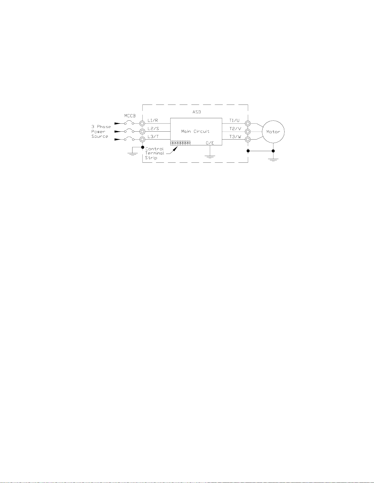
Connect the inpu t and output power lines of the ASD as shown in Figure 4.
Note: In the event that the motor rotates in the wrong direction when powered up, reverse
any two of the three A SD output power leads connec ted to the motor.
Figure 4. ASD/Motor connection diagram.
Connect the 3-phase input power to the input terminals of the ASD at L1/R, L2/S, and L3/T. Connect
the output of the ASD to the motor from terminals T1/U, T2/V, and T3/W. The input and output
conductors and terminal lugs used shall be in accordance with the requirements listed in the section
titled
Cable/Terminal Specificat ions on pg. 195.
If multiple conductors are used in parallel for the input or output power and it is necessary to use
separate conduits, each parallel set shall have its own conduit and not share its conduit with other
parallel set s (i.e., place U1, V1, and W1 in one conduit and U2, V2, and W2 in another) (refer to NEC
Article 300.20 and Article 310.4). National and local electrical codes should be referenced if three or
more power conducto rs are run in the same conduit (refer to 2002 NEC Article 310 adjus tm ent factors).
Figure 18 on pg. 30).
Note: National and local codes should be referenced when running more than three
conductors in the same conduit.
Install a molded c ase ci rcuit bre aker (MCC B) or fuse bet ween the 3-ph ase power sourc e and th e ASD in
accordance with the fault current setting of the ASD and 2002 NEC Article 430.
CAUTION
For 600 volt ASDs, the 15 HP or less ASDs (P/N VT130G7U6015B – 6160B) require a class-J fuse
rated at 600 Volts/30 A.
A phase-shifting transformer (or other means) must be supplied by the user when configured for 12pulse operation.
External fuses are r equired on the ASDs listed below when configured for 12-pulse operation .
VT130G7U2600B(DR)
VT130G7U2750B(DR)
VT130G7U412KB(DR)
VT130G7U415KB(DR)
VT130G7U610KB(DR)
VT130G7U612KB(DR)
VT130G7U615KB(DR)
Use either the Ferraz Shawmut Semic onductor fuse (P/N A70QS200) and fuse bloc k P234C, or the
Toshiba ASD-FUSEKIT-12P. The Toshiba kit includes the required fuses and the mounting hardware
for the fuses.
20 G7 ASD Operation Manual
Page 27

Lead Length Specifications
Adhere to the NEC and any local codes during the installat ion of ASD/Motor systems. Exces si ve lead
lengths may adversely effect the performance of the motor. Special cables are not required. Lead lengths
from the ASD to the motor in excess of those listed in
of the ASD. Table 2 lists the suggested maximum lead lengths for the listed motor voltages.
Table 2.
Table 2 may require filters to be added to the output
Model
230 Volt All 1000 feet
460 Volt
600 Volt
Note: Contact Toshiba for application as si stance when using lead le ngths in excess of those
listed.
PWM Carrier
Frequency
< 5 kHz 600 feet
≥ 5 kHz 300 feet
< 5 kHz 200 feet
≥ 5 kHz 100 feet
NEMA MG-1-1998 Section IV Part 31
Compliant Motors
2
Exceeding the peak voltage rating or the allowable thermal rise time of the motor
insulation will reduce the life expectancy of the motor.
For proper operation, the carrier frequency must be 2.2 kHz or above except when
operating in the Constant Torque, Variable Torque , or the 5-Point Setting modes.
Startup and Test
Perform the following checks before turning on the unit:
• L1/R, L2/S, and L3/T are connected to the 3-phase input power.
• T1/U, T2/V, and T3/W are connected to the motor.
• The 3-phase input voltage is within th e s pecified tolerance.
• There are no shorts and all grounds are secured.
G7 ASD Operation Manual 21
Page 28
I/O and Control
The ASD can be controlled by s everal input type s and combinations thereof, as well as operate within a
wide range of output frequency and voltage levels. This section disc usses the ASD c ontrol methods and
supported I/O func tions.
The Control Terminal Str ip PCB (P/N 4857 0) support s discrete and ana log I/O func tio ns and is shown
in
Figure 6 on pg. 25. Table 3 lists the names, the default settings, and the descriptions of the input and
output termin als of the Control Terminal Strip PCB.
Note: To use the input control lines of the Control Te rmi nal Strip the Comman d M ode
setting must be set to Use Control Terminal Strip (Program ⇒ Fundamental
Parameters ⇒ Standard Mode Selection ⇒ Command Mode ⇒ Use Control
Terminal Strip).
Figure 18 on pg. 30 shows the basi c connection diagram for the G7 system.
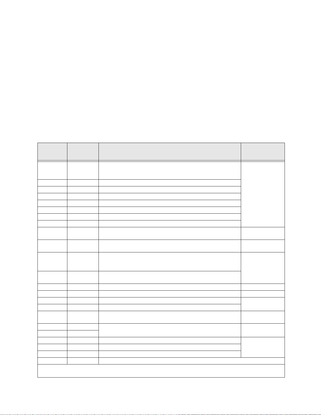
Table 3. Control Terminal Strip default assignment terminal names and functions.
Default
Term.
Setting
ST Discret e Input
RES Discret e Input Reset — Multifunct ional program m able discre te input.
F Discret e Input Forward — Multifunctional programmable discrete input.
R Discret e Input Reverse — Multifunctional programmable discrete input.
S1 Discret e Input Preset Speed 1 — Multifunctional programmabl e discrete input.
S2 Discret e Input Preset Speed 2 — Multifunctional programmabl e discrete input.
S3 Discret e Input Preset Speed 3 — Multifunctional programmabl e discrete input.
S4 Discret e Input Emergency Off — Multifunctional programmable discrete input.
RR Analog Input
RX Analog Input
II Analog Input
VI Analog Input
P24 DC Output 24 VDC @ 50 mA output. Figure 12 on pg. 29.
PP DC Output PP — 10.0 VDC volta ge source for the external potentiomet er. Figure 13 on pg. 29.
OUT1 Discrete Output Low Frequency — Multifunctional programmable discrete output.
OUT2 Discrete Output Reach Frequency — Multifunctional programmable discrete output.
FP Output
AM Output
FM Output
FLC Output F a ul t re la y (co m m o n) .
FLA Output F a ul t re la y (N. O .) .
CC — Control common (Do Not connect to Earth Gnd).
Discrete Input Terminals ⇒ Connect to CC to activate.
Analog Input Terminals reference CC.
Input/Output
(also see
Standby (jumper to CC to operate the unit) — Multifunctional
programmable discrete input (see
inform ation on this terminal).
RR — Multifunction programmable analog input
(0.0 to 10 volt input — 0 to 80 Hz output ). Reference CC.
RX — Multifunctional programmable analog input
(-10 to +10 VDC input — -80 to +80 Hz output). Refere n ce CC.
II — Multifuncti onal programmable analog input (4 [0] to 20 mADC
input — 0 to 80 Hz output) (see
the II terminal). Reference CC.
VI — Multifunctional programmable analog input
(0 to 10 VDC input — 0 to 80 Hz output). Refere nce CC.
Frequency Pulse — an output pulse train th at has a frequency which is
based on the output frequency of the ASD.
Produces an output current that is proportional to the magnitude o f the
function assigned to this terminal (see
Default Function
Terminal Descriptions on pg. 23)
Installation Notes on pg. 17 for further
Figure 6 on pg. 25 for the location of
Table 7 on pa ge 61).
Circuit Config.
Figure 8 on pg. 29.
Figure 9 on pg. 29.
Figure 10 on pg. 29.
Figure 11 on pg. 29.
Figure 14 on pg. 29.
Figure 15 on pg. 29.
Figure 16 on pg. 29
Figure 17 on pg. 29.FLB Output Faul t re la y (N. C .) .
22 G7 ASD Operation Manual
Page 29

Terminal Descriptions
Note: The programmable term inal assignments may be accessed and changed from their
default settings as mapped on
Direct Acce ss ⇒ applicable parameter number. See th e s ectio n tit le d Pr ogram Mode
on pg. 47 for the applicable Direct Access parameter numb e rs.
For further information on terminal assignments and default setting changes, see the
section tit led
on pg. 47.
ST — The default setting for this terminal is ST. The function of this input as ST is a Standby mode
controller (system is in Sta ndby when on). As the default setting, this terminal must be connected to
CC for normal operation. If not connected to CC, Off is displayed on the LCD screen. This input
terminal may be programm ed to any 1 of the 68 possible functions that are listed in
(see F113).
RES — The default setting for this terminal is RE S. The function of this input as RES is a system
Reset. A momentary connection to CC resets the ASD and any fault indications from the display. This
input terminal may be programmed to any 1 of the 68 possible functions that are listed in
page 76 (see F114). Reset is effective when faulted only.
F — The default setting for this termina l is F. The func tion of this input as F is Forward Run. A
connection to CC runs the motor in the Forward direction when it is on. This input terminal may be
programmed to any 1 of the 68 poss ible functions that are listed in
Output Terminal Functi ons on pg. 49 and CHANGED FROM DEFAULT
pg. 47 or via the Direct Access method: Program ⇒
Table 8 on page 76
Table 8 on
Table 8 on page 76 (see F111).
R — The default setting for this terminal is R. The functi on of this input as R is Reverse Run. A
connection to CC runs the motor in the Reverse direction when it is on. This input term inal may be
programmed to any 1 of the 68 poss ible functions that are listed in
S1 — The default setting for this terminal is S1. The function of this input as S1 is to run the motor at
Preset Speed #1 (see
to any 1 of the 68 possible functions that are list ed in Table 8 on page 76 (see F115).
S2 — The default setting for this terminal is S2. The function of this input as S2 is to run the motor at
Preset Speed #2 (see
to any 1 of the 68 possible functions that are list ed in Table 8 on page 76 (see F116).
S3 — The default setting for this terminal is S3. The function of this input as S3 is to run the motor at
Preset Speed #3 (see
to any 1 of the 68 possible functions that are list ed in Table 8 on page 76 (see F117).
S4 — The default setting for this terminal is Emergency Off (normally closed). The function of this
input as Emergency O ff is to remove power from the output of the ASD and may apply a supplemental
braking sys tem using the method se lected at
the 68 possible func tions that are listed in Table 8 on page 76 (see F118).
RR — The default function assigned to this terminal is to ca rry out the Frequency Mode #1 setting.
The RR terminal accepts a 0 – 10 VDC input signal that controls the function assigned to this ter mi nal.
This inpu t terminal may be programmed to control the speed or torque of the motor. It may also be used
to regulate (li mi t) the speed or torque of the motor. The gain and bias of this terminal may be adjust ed
for appli cation - sp ecific s u it ab i li ty ( see
Preset Spee d #1 on pg. 66) wh en it is on. This inp ut termi nal may be progra mmed
Preset Spee d #2 on pg. 66) wh en it is on. This inp ut termi nal may be progra mmed
Preset Spee d #3 on pg. 67) wh en it is on. This inp ut termi nal may be progra mmed
F603. This input terminal may be programmed to any 1 of
F210 – F213).
Table 8 on page 76 (see F112).
RX — The RX termina l accepts a ±10 VDC input signal tha t controls the function assigned to this
terminal. This inp ut term inal m ay b e progr ammed t o con trol the sp ee d, tor que, or dire ct ion of the mo tor.
It may also be used to regulat e (limit) the speed or torque of the moto r. The gain and bias of this
terminal m ay be adjusted for ap plication-sp ecific suitability (se e
G7 ASD Operation Manual 23
F216 – F219).
Page 30

II — The function of the II input is to receive a 4 – 20 mA input signal that controls a 0 – 80 Hz output.
This input termi nal may be programmed to control the speed or torque of the motor and may not be used
when us in g th e VI inp u t. Also, the gai n and bias of this ter minal may be adjus ted (see
F201 – F204).
VI — The function of the VI input terminal is to receive a 0 – 10 VDC input signal that controls a
0 – 80 Hz output. This input te rminal may be programmed to control the speed or torque of the motor and
may not be used when using the II input. Also, the gain and bias of this terminal may be adjusted (see
F201 – F204).
P24 — +24 VDC @ 50 mA power supply for customer use.
PP — The function of output PP is to pro vide a 10 VDC outp ut that m ay be divi ded usi ng a potent iome ter.
The tapped voltage is applied to the RR input to provide manual control of the RR programmed function.
OUT1 — The default setting for this output terminal is the Output Low Speed indicator. This output
terminal may be programm ed to provide an indication that 1 of 60 possible events has taken place. This
function may be used to signal external equipment or to activate the brake (see
F130). The OUT1 contact
is rated at 2A/250 VAC.
OUT2 — The default setting for this output terminal is the ACC/DEC Complete indicator. This output
terminal may be programm ed to provide an indication that 1 of 60 possible events has taken place. This
function may be used to signal external equipment or to activate the brake (see
F131). The OUT2 contact
is rated at 2A/250 VAC.
FP — The default function of this output terminal is to output a series of pulses at a rate that is a function
of the output frequen cy of the ASD. As the output frequency of the ASD goes up so does the FP output
pulse rate. This term inal may be programmed to provide output pulses at a rate that is a function of the
output frequency or the magnitude of any 1 of the 31 the functi ons listed in
Table 7 on pg. 61 (see F676).
AM — This output te rminal produces an output curre nt that is proportiona l to the output frequency of the
ASD or of the magnitude of the function assigned to this terminal. The available assignments for this
output termin al a r e listed in
Table 7 on page 61. For further information on this terminal see F670 on pg.
163.
FM — This output terminal produc es an output current that is proportional to the output frequency of the
ASD or of the magnitude of the function assigned to this terminal. The available assignments for this
output termin al a r e listed in
Table 7 on page 61. For further information on this terminal see F005 on pg.
60.
FLC — FLC is the middle leg of a singl e-po le double -thr ow (relay) s witch. This FLC contact of the relay
is switche d betwee n FLB and FLA. This contact may be programmed to switc h betwe en FLB and FLA as
a function of any 1 of the 60 conditions listed in
Table 9 on page 81 (see F132 and Figure 5 on pg. 24).
FLB — One of two contacts that, under user-defined conditions, connect to FLC (see Figure 5 on pg. 24).
FLA — One of two contacts that, under us er-defined conditions, connect to FLC (see Figure 5 on pg. 24).
Note: The FLA and FLC contacts are rated at 2A/250 VAC. The FLB contact is rated at 1A/
250 VAC.
CC — Control common (Do Not connect to Eart h Gnd).
Figure 5. FLA, FLB, and FLC switching contacts shown in the de-energized state.
Note: Th e r el a y is sh o wn in the Faulted or
de-energized condition. During
normal system oper ation the relay
connection is FLC-to-FLA.
24 G7 ASD Operation Manual
Page 31

Figure 6. Control Terminal Strip PCB.
1
SW1 and SW2 may be
switched to change the fullscale reading of the AM and
FM output terminals. See
F670 and F005 for further
information on the AM and
FM terminal adjustments.
CN7A
{
0–1 mA 4–20 mA
SW1
0–1 mA 4–20 mA
SW2
TB
{
II Terminals
The input and output terminals of the Control Terminal Strip. For further information on
these terminals see pg. 22.
RES
G7 ASD Operation Manual 25
RRP24
F
ARS1S2S3S4C CA
OUT1 OUT2
Page 32

G7 ASD Control
r.
l
The Control PCB (P/N 56000) serves as the primary control source for the G7 ASD and receives input
from the Control Terminal Strip PCB (see
Communications, or the EOI.
The Control PCB has been enhanced to support two new functions: Multiple Pr otocol Communications
and the ability to communicate in either half- or full-duplex mode s.
Using the optional multiple-protocol communications interface; the ASD-NANOCOM, the Control
PCB may be configured for the type of co mmunications protocol being received and respond
appropriate ly to the sending device. The ASD-NANOCOM connect s to the J4 and J5 connectors
(see Figure 7). A jumper PCB (P/N 55365) is required at the J4 connector if not using the ASDNANOCOM.
The ASD-NANOCOM must be setup to support the des ired communications protocol via Program ⇒
Communication Setting Parameters ⇒ Communication Settings. Consult the ASD-NANOCOM
User’s Manual (P/N 10572-1.000-000) for a complet e listing of the setup requirements.
Half or Full duplex com mun ications is avail able when using RS232/RS485 communications. The
jumpers at the JP1 and the JP2 connectors may be moved from one pos ition to the other to facil itate
either half- or ful l-duplex operation. If no jumper s are used the system will operate in the full duplex
mode.
Figure 6 on pg. 25), an Option Card, RS232/RS485
For more information on the G7 ASD communication requirements, please visit
WWW.TIC.TOSHIBA.COM to acqui re a copy of the 7-Series Communications Use r Manual and
WWW.ICCDESIGNS.COM to acquire a copy of the ASD-NANOCOM User Manual.
Contact your Toshiba representative if more inform ation is required on the ASD-NANOCOM.
Figure 7. Control Board of the G7 ASD (P/N 56000).
EOI connection and
Common Serial
(TTL) I/O (CNU2).
RS232/RS485
signal I/O (CN3).
RS232/RS485
signal I/O (CNU1).
CNU4
CN8
CN2
CNU3
25-pin D-type connecto
Connects to the Control Termina
Strip PCB (CN7).
JP1 jumpers - Half-/Full- Duplex selection.
26 G7 ASD Operation Manual
ASD-NANOCOM.
Page 33

CNU1/1A and CNU2/2A Pinout
Pin #
1 P24 P24 1 P24 P24
2 Gnd Gnd 2 Gnd Gn d
3 Tx (-) RXA 3 Rx Tx
4 Rx (+) TXA 4 Gnd Gnd
5 Rx (-) TXB 5 Tx Rx
6 Tx (+) RXB 6 Gnd Gnd
7 RS232/RS485 CNU3 Pin-7 7 Open Open
8 Gnd Gnd 8 Gnd Gn d
CNU1 Pinout
(Controller PCB)
CNU1A Pinout
(EOI)
Pin #
CNU2 Pinout
(Controller PCB)
Note: For normal operat ion, connect CNU1 to CNU1A or CNU2 to CNU2A. DO NOT
connect both. If both are connect ed, the TTL and RS232/
RS485 signals will be
transferred simultaneously to and from the EOI and the control board resulting in a
Communications Lost error message or erratic ASD operation.
Note: Connecting CNU1 to CNU2A will result in a continuous splash screen display.
Connect CNU1 to CNU1A and continue normally.
Connecting CNU2 to CNU1A will result in a continuous splash screen display.
Connect CNU2 to CNU2A and continue normally.
CNU2A Pinout
(EOI)
Note: See the 7-Se ries Communications Manual (P/N 53840) for further information on the
G7 communications protocol and system configuration require ments.
CN3 Pinout‘
CN3 is used for RS232/RS485 serial communicat ions.
Pin Number
1 RS232/RS485 Signal +
2 RS232/RS485 Signal 3 RS232/RS485 Signal Gnd
4 Shield
CNU3 Pinout
(Controller PCB)
G7 ASD Operation Manual 27
Page 34

CN7 Pinout
Listed below is the pinout of the CN7 conne ctor. The CN7 connector is the 25-pin D-type connector of
the Control Board (see
Table 4. CN7 pinout ass ignments. Listed are the default settings for programmable terminals.
Figure 7).
Pin Number
1 PP 14 II
2 FL 15 S1
3 VI 16 R
4 RR 17 S3
5 FM 18 S2
6 RX 19 N15
7 FP 20 S4
8 AM 21 P15
9 *OUT1 22 P24
10 *OUT2 23 CC
11 ST 24 CC
12 RES 25 CC
13 F — —
Note: * Open collector outputs.
CN7
PInout
Pin Number
CN7
PInout
28 G7 ASD Operation Manual
Page 35

I/O Circuit Configurations
Figure 8. Discrete input. Figure 9 RR input.
Figure 10 . RX input. Figure 11. VI/II input.
Figure 12 . P24 Output. Figure 13. PP Output.
Figure 14 . OUT1/OU T2 Outp ut. Figure 15. FP Output.
Figure 16 . AM/FM Output. Figure 17. Fault Relay (during fault).
G7 ASD Operation Manual 29
Page 36

Typical Connection Diagram
Figure 18 . G7 typical connection diagram.
Note: When connecting multip le wires to the PA, PB, PC, or PO
terminals, do not connec t a sol id w ire an d a strande d wi re to the
same terminal.
Note: The AM, FM, VI, and II analog terminals are reference d to CC.
Note: See alternative ST-to-CC activation configuration on pg. 17.
30 G7 ASD Operation Manual
Page 37

Command Mode and Frequency Mode
Control
Command control includes instr uctions such as Stop, Run, Jog, etc. The source of the Command
signal must be estab lished for normal operation.
Frequency commands control the output speed of the ASD. The source of the frequency (speed)
control signal m ust be established for normal operat ion.
The source of the command control and speed control may be either internal or external. Once the
source signal is selected for either function, the system may be configured to us e the selected signal all
of the time or switch under user-defined conditions.
Command and Frequency control may be carried out using any one of several con trol methods (si gnal
sources) or combi n ations ther eof. In the event that multiple control com mands are received, th e signal
sources are assig ned priorit y le vels. Th e primary cont rol method for Command and Frequency control
uses the settings of
Command Con tro l (F003 )
The Command Mode selection of F003 establishes
the primary sourc e of the command input for the ASD.
However, the Override fea ture may supersede the
F003 setting as indicated in Table 5.
F003 and F004, respectively.
Table 5 shows t h e h i erarchy of the control sources
managed by the Override function. The level of the
contro l item on th e hierarc hy is li sted fro m left to
right, most to least, respectively. As indicated in the
table , th e Override setting may supersede the
Placing the EOI in the Local mode selects either the RS232/RS485 or the Common Serial (TTL) as
the Com mand Mode control source. Once in the Local mode, the LCD Port Connection setting
determines if the RS232/RS485 or the Common Serial (TTL) will be used for Command control.
Local mode operation may be superseded by other C o mmunica tions Override settings.
Example: With the EOI se t to Local and the LCD Port Connection set to Common Serial (TTL),
setting the Communication Card or RS232/RS485 control to Override will supersede the Common
Serial (TTL) setting.
The remaining con trol sources may be placed into the override mode using communications.
The source of the Command control signal may be selected by:
•The F003 setting,
• Placing an item from the list below in the Override mode via communications, or
• Plac ing the EOI in the Local mode (places only the RS232/RS485 or the Common Serial [TTL] in
the Override mode).
Possible Command signal source selections include the following:
• Use Control Terminal Strip (default),
F003 setting.
• Use LED Keypad Option,
• Use Common Serial (TTL),
• Use RS232 /RS 485,
G7 ASD Operation Manual 31
Page 38

• Use Communication Card, or
• F003 setting (is used if no signal sources are in the Override mode).
Note: The Control Terminal Strip is placed in the Override mode by assigning a discrete
terminal to Command Control Terminal Strip Priority and connecting the terminal
to CC. Once activated (Run command required), the Control Terminal Strip settings
will be used for Override Command control (F, R, Preset Speeds, etc.).
Frequency Control (F004)
The Freq uenc y Mode #1 (or the Frequency Mode
#2) setting establishes the user -selected source of the
frequency-control input for the ASD. The signal
source selected here is used for speed control unless
the R e fe rence Prio r it y Selectio n parameter is
configured to automatically switch this setting (see
F200) or if the Override featu re is en a bl ed ( vi a
communications or via the Local mode operation).
Table 5 shows the hiera rchy of the control sourc es managed by the Override function. The level of the
control item on the hierarchy is listed from left to right, most to least, respectively. As indicated in the
table , th e Override setting may supersede the selection at
Placing the EOI in the Local mode selects either the RS232/RS485 or the Common Serial (TTL) as
the Frequency Mode #1 control source. Once in the Local mode, the LCD Port Connection setting
determines if the RS232/RS485 or the Common Serial (TTL) will be used for Frequency Mode #1
control. Local mode operation may be superseded by other Communications Override settings.
F004.
Example: With the EOI set to Local and the LCD Port Connection set to Common Serial (TTL),
setting the Communication Card or RS232/RS485 control to Override will supersede the Common
Serial (TTL) setting.
The remaining con trol sources may be placed into the override mode using communications.
The source of the Frequency control signal may be selected by:
•The F004 setting,
• Placing an item from the list below in the Override mode via communications, or
• Plac ing the EOI in the Local mode (places only the RS232/RS 485 or Common Serial in the
Override mode).
Possible Frequency control source selections include the following:
• Communication Card,
• RS232/RS485,
• Common Serial (TTL),
•LED Keypad,
• Control Terminal Strip (default setting), or
• F004 settin g ( used if no other items are in the Override mode).
Note: The Control Terminal Strip is placed in the Override mode by assigning a discrete
terminal to VI/II Terminal Priority and connecting the terminal to CC. Once the
discrete terminal is activated, VI/II is used as the Control Termina l Strip Ove rri de
contr o l it em .
32 G7 ASD Operation Manual
Page 39

Command and Freq ue nc y Control Selections
The user may select only one Command source and only one source for Frequency control. The
default settings for Command and Frequency control are Use Control Terminal Strip and Use RR,
respectively.
The G7 ASD has a command register for each ite m listed as a Command or Frequency source. The
registers store the Override setting for each control source. The r egisters are continuously scanned to
determine if any of the listed items are in the Override mode.
For each scan cycle, the co mm and registers of the control sou rces ar e scanned for the Override setting
in the order that they are listed in
the F requency section detect ed as being in th e Override mode will be used for Command and
Frequency control , re spec tiv el y. If no items are de tect ed as bei ng in th e Override mode, the settings of
F003 and F004 will be use d for Command and Frequency control, respectiv ely.
Any or all of the Command and Frequency control input sources may be placed in the Override
mode.
Placing the G7 ASD in the Local mode (Local/Remote LED on) via the EOI places the RS232/RS485
or the Common Serial (TTL) control selections in the Override mode for Command and Frequency
input (see the section titled
control Override feature for Command and Frequency (or either) may be en abled/ disable d at P rogram
⇒ ΕΟΙ Option Setups ⇒ Local-Remote Key (enabled with check in box).
Communications may be used to place the rema ini ng Command and eligi ble Frequency control input
sources in the Override mode. Once placed in the Override mode this setting is valid until it is
cancelled, the power supply is turned off, or the unit is reset.
Table 5. The first item of the Command section and the first item of
Override Operation below for th e p r op er sett in g ) . Th e Local/Remote
G7 ASD Operation Manual 33
Page 40

Override Operation
The command registers of the listed signal sou r ces are scanned in the order th at they are listed in
Table 5 to determine which input sources are in the Override mode. Du ring each re gis t er scan cycle , th e
first item det ecte d as havin g the Override func tion t urne d on is t he sele ction t ha t is use d for Command or
Frequency control input.
The Override control set ting supersedes the setting of the Command mode setting (F003) and the
Frequency mode setting (F004). However, the F003 and F004 setting s will be used in the event that the
register scan returns the condition that none of the listed items have the Override featu r e tu r n ed on (see
Table 5).
Command and Freq ue nc y-Control Overr ide Hie r a r chy
Table 5 lists the input conditions and the resulting output control source selections for Command and
Frequency control Override operation. The G7 ASD reads the command registers of the listed control
items fr om th e le ft t o th e r ig ht. In t he t abl e t he n umb er 1 i nd ica te s th at th e O ve rrid e fe at ur e is turn ed on for
that control input source; X = Don’t are; and 0 = Override Off .
The first item to be read that has the Override feature turned on will be used for Command or Frequency
control.
1 2 3 4 5 6 Priority Level
Communication
Card
1 X X X X X Communication Card
0 1 X X X X RS232/RS485
0 0 1 X X X Common Serial
0 0 0 1 X X Panel (LED Keypad)
0 0 0 0 1 X Control Terminal
0 0 0 0 0 F003/F004 Setting F003/F004 Setting
RS232/
RS485
Table 5. Command an d Frequency control hierarchy.
Common
Serial
Panel
(LED
Keypad)
Control Terminal
(Binary/BCD Input)
F003/F004
Command/
Frequenc y Mode
Command Control Selections
The following is a listing and description of the
Command Mode (
Fundam ent al P ara mete rs ⇒ S tanda rd Mode Sel ecti on ⇒
Command Mode)
Settings:
Use Control Terminal Strip
Allows for Command control input via th e 25-pin
terminal strip on the Control Terminal Strip PCB.
Use LED Keypad Option
The LED Keypad is unavailable at the time of this release .
Use Common ( TTL)
Set the LCD Port Connection to Common Serial (TTL) to use this feature.
Use RS232/RS485
Set the LCD Port Connection to RS232/RS485 to use this feature.
Use Communication Card
Rout es th e cont r o l an d m on i to r ing I/O to CN U 3 of the Control Board of the G7 ASD
(Communication Card connector).
34 G7 ASD Operation Manual
F003) selections (Program ⇒
.
Page 41

Frequency Control Selections
The following is a listing and description of the
Frequency Mode (
Funda m enta l P ar a m eters ⇒ Standard Mode Selection
⇒ Frequency Mode #1).
Settings:
Use VI/II
0 to 10-volt DC analog input conn ecte d to VI or a
4 – 20 mA (or 0 to 1 mA) DC curren t conne cted to
II (cannot use both simultaneously).
Use RR
0 to 10-volt DC analog input connected to RR.
Use RX
-10 to +10-volt DC analog input connected to RX.
Use Option Card RX2
-10 to +10-volt DC analog input connected to RX2.
Use LED Keypad Option
The LED Keypad is unavailable at the time of this release.
F003) selections (Program ⇒
Use Binary/BCD Input
Allows for discret e terminal input to control the ASD output .
Use Common Seri al (TTL)
To use the EO I for co n tro l requ i re s th at th e LCD Port Connection be set to Common Serial
(TTL) to use this feature.
Use RS232/RS485
To use the EO I for co n tro l requ i re s th at th e LCD Port Connection be set to RS232/RS485 to use
this feature.
Use Communication Card
Rout es th e cont r o l an d m on i to r ing I/O to CN U 3 of the Control Board of the G7 ASD (Option
Card connector).
Use Motorized Pot Si mulation
A discrete termina l may be configured to increase or decrease the speed of the motor by
momentarily connecting the assigned terminal to CC. See
information on this feature.
Use Pulse Input Option
Configures the system to receive pulse input. See PG Speed Reference Setpoint on pg. 103 for
further information on this feature.
Table 8 on page 76 for further
G7 ASD Operation Manual 35
Page 42

Electronic Ope rat or In terf ace
The G7 Elec tronic Operator Interface (EOI) is comprised of an LCD display, two LEDs, a rotary
encoder, and eight keys. These ite ms are described below and their locations are provide d in
Figure 19 on pg. 37.
The EOI can be mounted remotely from the ASD a s described in the section titl ed EOI Remote Mounting
on pg. 190. The dimensional requirements for remot e mounting may a lso be found in this secti on. Using a
screw length that exceeds the specified dimensions may cause deformation of the outer surface of the
bezel as shown in
The interface ca n operate up to distances of 15 feet from the ASD via the Common Serial (TTL) Port. For
distances beyond 15 feet, the RS232/RS485 port is recommended.
EOI Features
LCD Display — Displays configuration information, performance data (e.g., motor frequency, bus
voltage, torque, etc.), and diagnostic information.
Local|Remote Key — Toggles the system to and from the Local and Remote modes. The LED is on
when the system is in the Local Command mo de . The Local mode allows the Command and Frequency
control functions to be carried out via the EOI.
The Remote mode enables the Command and Frequency control functions to be carried out via the
Control Terminal Strip, LE D K eypad, RS232/RS485, Communication Card, or Pulse Input. The
selection may be made via
Mode.
Figure 31 on pg. 192 and should be avoided.
Program ⇒ F un damental Parame ters ⇒ Standard Mode Settings ⇒ Command
Note: The LED Keypad is under dev elopment and is unavailable at the time of the release of
this manual.
The availability of the Local mode of operation (Command and Frequency control) may be disabled via
Program
may be reinstated by changi ng this setting or performing a Reset (see F007).
Enter Key — Selects a menu i tem to be changed or accept s and reco rds the changed data of the select ed
field (same as pressing the Rotary Encoder).
Esc Key — Retur ns to the previous level of the menu tree, toggles between the Panel and the Frequency
Command s cre ens, or cancels changes made to a fie ld if pressed while still in the reverse video mode
(dark background/light text). The 3 functions are menu-specific.
Run Key — Issues t h e Run command while in the Local mode.
Run Key Status LED — Illuminates green while stopped or red while running.
Stop Key — Issues the Off command (decelerates to Stop at the programmed rate) if pressed once while
in the Local mode or initiates an Emergency Off (terminates the ASD output and applies the brak e if s o
configured) if pressed twice quickly from the Local or Remote modes.
Up Key — Increases the value of the selected parameter or scrolls up the menu listing (continues during
press-and-hold).
⇒ EOI Option Setups ⇒ Local/Rem o t e K ey . The availability of the Local mode of operation
Down Key — Decreases the value of the selected parameter or scrolls down the menu listing (continues
during press-and-hol d).
36 G7 ASD Operation Manual
Page 43

Rotary Encoder — Functions as the Up key, the Down key, and the Enter key. Turn the Rotary
Encoder eith er clockwise or cou n terclock wise to perform the Up or Down key functions. Press the
Rotary Encoder to perform the Enter function. Simultaneously pressin g and turning the Rotary
Encoder performs a user-de fined fun ction (se e Program ⇒ EOI Option Setup ⇒ Preferences ⇒
Action).
MON/PRG (Monitor/Program) — Provides a means to access the three root menus. Pressing the MON/
PRG key repeatedly loops the system through the three root menus (see
Figure 21 on pg. 43). While
looping through t he root menus, the Program menu will display the las t menu screen or sub-menu item
being accessed at th e time that the MON/PRG key was pressed.
Figure 19. The G7 Electronic Operator Interface.
LCD Display
Enter K e y
Encoder
Local/Remote
Key (LED)
Monitor/Program
Key
Run Key
(LED)
Up/Down Arrow
Keys
Rotary Encod er
Esc Key
Stop
|
Reset Key
EOI Operation
The EOI is the primary input/output device for the us er. The EOI may be used to monitor system
functions, in put data into the system, or pe rform diagnostics.
Note: The Up/Down arrow keys and the Enter key may be used to perform the fu nctions of the
Rotary Encoder. The Rotary Encoder will be used in this explanation and throughout
this manual for the Up, Down, and Ente r key functions.
The software used with the G7 is menu driven; thus, making it a sele ct and click environment . Th e
operating parameters of a motor may be selected and viewed or changed using the EOI.
To change a parameter setting, go to the Program mode by pressing the MON/PRG key until the
Program menu is d is played. Turn the Rot a ry Encode r until the desired parameter group is within the
cursor block. Press the Rotary Encoder (repeat if there is a submenu).
The selection will take on the reverse video format (dark background/light text). Turn the Rotary
Encoder to change the value of the parameter. Press the Esc key while the display is in the reverse video
mode to exit the menu without saving the change or press the Rotary Encoder to accept the new setting.
Repeated Esc key entries takes the menu back one level each time the Esc key is pressed until the root
level is reached. After reac hing the root l evel, continu ed Esc entr ies wil l toggle the syst em to an d fr om the
Frequency Command screen and the Panel menu.
Note: Panel menu changes entered here will affect EOI-controlled ASD operation only. LED
Keypad-contr olled functions wi ll not be affected. LED Keypad-controlled opera tion
settings may be viewe d or changed at
F008. See the sec tion tit le d Panel Menu on pg. 44
for further inf ormation on Panel Menu operations.
G7 ASD Operation Manual 37
Page 44

System Operation
Initial Setup
Upon initial syste m power up, the Startup Wizard starts automatically. The Startup Wizard assists the
user with the initial configuration of the input power settings and the output parameters of the G7 ASD.
The ASD may also be setup by directly accessing each of the individual paramet ers (see the section titled
Direct Access Parameter Information on pg. 59).
The Startup Wizard may also be selected and run from the Program menu after the initial startup if
required.
The Startup Wizard querys the user for the following information:
1. Run now? (if selected continue on to step #2)/Run next time at power up? (if selected go to
Program Mode)/Manually configure? (if selected go to Finish ⇒ Program Mode).
2. The Voltage and Frequency rating of the motor.
3. The Upper Limit frequency.
4. The Lower Limit frequency.
5. Adjust Accel/Decel times automatically? (if Yes, continue from step #8).
6. The Acceleration time.
7. The Deceleration Time.
8. The Volts/Hertz sett in g .
9. The motor Current rating.
10. The Command source.
11. The F requenc y Reference source.
See the se ct io n titled Startup Wizard Requirements on pg. 40 for ad ditional information on the Startup
Wizard.
Operation (Local)
Note: See F003 for inf ormation on Remote operation.
To turn the motor on, perform the following:
1. Press the MON/PRG key until the Frequency
Command screen is displayed.
2. Press the Local|Remote key to enter the Local
mode (green Local LED illuminates).
3. Turn the Rotary Encoder cl ockwise until the
Frequency Command valu e is at th e de sired
setting.
4. Press the Run key and the mot or runs at the
Frequency Command value.
Note: The speed of the motor may be changed while
the motor is running by using the Rotary Encoder to change the Frequency Command
value.
5. Press the Stop|Reset key to stop the motor.
38 G7 ASD Operation Manual
Frequency Command Screen
Page 45

Default Settin g Chang es
To change a default parameter setting, go to the root of the Program menu and turn the Rotary Encoder
until the desired paramete r group is within the cursor block and press t he Rotary Encoder (repeat if there
is a submenu).
Press the Rotary Encoder to select the defaul t settin g to be changed and the s elec tion tak es on the reverse
video format (dark backg r ound, light text) . Turn the Rotary Encoder to change the value of the
parameter. Press the ESC key before accepting the change to exit the menu without saving the change or
press the R ota r y E n co der to accept the n ew se tting.
For a complete listi ng of t he Program mode menu options, see the sec tio n title d Progra m Mode on pg. 47.
Menu items are lis t ed and mapped for con venience. The Direct Access Numbers are listed where
applicable.
The default setti ngs may al so be chan ged by enteri ng the Pa ram et er N umb e r of t he setti ng to be chang ed
at the Direct Access menu (Program
Direct Access Numbers and a description of the associated parameter may be found in the sectio n titled
Direct Access Parameter Information on pg. 59.
A listing of a ll parameters th at have been change d from the default s etting may be viewed sequentially by
accessing the Changed From Default screen (Program
⇒ Direct Access ⇒ Applicable Para mete r Number). A listi ng of t he
⇒ Chan ged Fro m D ef ault).
Note: Parameter F201 was changed to create the example s hown in Figure 20.
The Changed Fro m D efault feature allows the user to v iew (or chan g e) the parameters that are different
from the default or the post-reset se ttings. Once the Changed From Default screen is displayed, the
system automatically scrolls through all of the system parameters and halts once reaching a changed
parameter.
The Rotary Encoder may be clicked once clockwise to continue scroll ing forward or clicked once
counterclock wise to begin scrolling in reverse. With each click of the Rotary E nco d e r from a stop, the
system scrolls throu gh all of the parameters and stops at the next parameter that has been change d.
Pressing the Rotary Encoder while a changed parameter is displa yed acc esses th e set tin gs of the chan ged
parameter for viewing or chan ging.
Pressing ESC while the system is performing a Change d F rom Def ault search te r m i na te s th e s e ar ch .
Pressing ESC when done searc hing (or halted at a changed parameter) returns the syst em to the Program
menu.
Figure 20 . Changed From Default screen.
G7 ASD Operation Manual 39
Page 46

Startup Wizard Requirements
The Startup Wizard queries the user for information on the input and output signal parameters of the
ASD. The ASD may also be setup by directly acces sing each of the control set tings via the Program
menu or the Direct Access Numbers (see the section titled
59).
Upon initial syste m power up, the Startup Wizard starts automatically. It may also be run from the
Program menu after startup if required. The user is queried to either (1) run the Startup Wizard (Run
Now), (2) ru n th e Startup Wizard at the next power up, or (3) perform a manual setting of use r-selected
parameters.
If selection ( 2) is chosen, the system returns to the Program menu and defaults to the Startup Wizard on
the next power up. If selection (3) is chosen, click the s u b sequent Finish box and the system returns to the
Frequency Command screen. If selection (1) (Run Now) is selected , the Startup Wizard will start and
assist t he us e r with th e co n figu rat ion of the G7 True T o rque Control
following user-input screens.
Voltage and Frequency Rating of the Motor
Motors are designed and manufactured for a specific
voltage and frequency range . Th e voltage and frequency
specifications for a given motor may be found on the
nameplate of the motor.
Direct Access Parameter Information on pg.
2
Adjustable Speed Drive using t h e
Upper Limit Freq uency
This parameter sets the highest frequency that the G7 will
accept as a frequency command or frequency setpoint. The
G7 may output frequencies higher than the Upper Limit
Frequency (but , lo w e r th an the M axi mum Frequ enc y )
when operating in the PID Control mode , Torque Control
mode, or the Vector Co nt rol modes (sensorless or
feedback).
Lower Limit Fre quenc y
This p a r ameter sets the lo w e s t fr eq u e n c y th at the G7 wi l l
accept as a frequency command or frequency setpoint. The
G7 will output frequencies lower than the Lowe r L im it
Frequency when accelerating to the lower limit or
decelerating to a stop. Frequencie s below the Lower Limit
may be output when operati ng in the PID Control mode,
Torque Control mode, or the Vector Control modes
(sensorless or feedback).
40 G7 ASD Operation Manual
Page 47

Adjust Accel/De ce l Autom atica lly?
When enabled, the G7 adjusts the acceleration and
deceleration rates according to the applied load. The
acceleration and dec eleration ti mes range from 12.5% to
800% of the programmed values for the active
acceleration time [e.g., Acceleration Tim e #1 (
and Deceleration Time #1 (F010)].
The motor and the load must be conne cted prior to
selecting Automatic Accel/Decel.
If Automatic Accel/Decel is not enabled, the Acceleration screen w il l app ear follo w ed b y th e
Deceleration scre en as shown below .
F009)
Acceleration Time
Volts per Hertz Setting
This function establishes the relationship between
the output frequency and the output voltage.
Settings:
Constant Torque
Variable Torque
Automatic Torque Boost
Sensorless Vector Control (Speed)
Automatic Torque Boost + Automatic Energy Savings
Sensorless Vector Control (Speed) + Automatic Energy Savings
V/f 5-point Setting (Opens 5-point Setting Screen)
Sensorless Vector Control (Speed/Torque Switching)
PG Feedback Vector Control (Speed/Torque Switching)
PG Feedback Vector Control (Speed/Position Switching)
Deceleration Time
Motor Current Rating
This parameter allows the user to input the full-load
amperage (FLA) of the motor . This value is used by
the ASD to dete rm i ne th e Thermal Overload
protection setting for the motor and may be found
on the nameplate of the motor.
G7 ASD Operation Manual 41
Page 48

Command Source
This selection allows the user to establis h the source
of the Run commands (e.g., F, R, Stop, etc.).
Settings:
Use Control Terminal Strip
Use LED Keypad Option
Use Common Serial (TTL) — (Use for LCD
EOI Operation)
Use RS232/RS485
Use Communication Car d
Frequency Reference Source
This selection allows the user to establish the source
of the Frequency (speed) command.
Settings:
Use VI/II
Use RR
Use RX
Use Option Card RX2
Use LED Keypad Option
Use Binary/BCD Input
Use Common Serial (TTL) — (Use for LCD EOI Operation)
Use RS232/RS485
Use Communication Car d
Use Motorized Pot Simulation
Use Pulse Input Option
Wizard: Finish
This screen is the final screen of the Startup Wizard.
The basic parameters of the ASD have bee n set. Click
Finish to return to the Program mode. Additional
application -specific programming may be required.
42 G7 ASD Operation Manual
Page 49

System Configuration and Menu Options
Root Menus
The MON/PRG key accesses the three primary modes of the G7: the Frequency C ommand mode, the
Monitor mode, and the Program mode . F r om eit h er m o de , p re ss th e MON/PRG key to loop through to
the other two modes (see
toggles the menu to and from the Panel menu and the F requency Command mode.
Note: Panel menu changes made when accessing the Panel menu using the method shown in
Figure 21 is effective for Local LCD EOI control Only.
Figure 21 . Root menu mapping.
Figure 21). While in th e Frequency Command mode, pressing the ESC key
Frequency Command Mode
Freque ncy Setting
While operating in the Local mode (Local LED is ill uminated on the front panel), the running frequenc y
of the motor may be set from the Frequency Command screen. Using the Rota ry Encoder, enter the
Frequency Command value and then press the Run key. The motor will run at th e Frequency
Command speed and may be changed while running.
Scrolling Monitor
The Output Current and the ASD Load values are displayed (defaul t setting) below the Frequency
Command parameter of the Frequency Command screen. Other user-select ed pa rameters may be
displayed on this screen for quick-access monitoring while running. These parameters may be accessed
and enabled for di sp lay by placing a check in the box next to the item listed at Progra m ⇒ Monitor Setup
Scrolling Monitor Select. If no parameters are enabled for display, No Items is displayed.
⇒
When more than two items are selected for display the items are scrolled automatically. The display time
for each selected item may be set from 1 to 60 seconds. The parameters that may be displayed on the
Scrolling Monitor are list ed in the section titled
G7 ASD Operation Manual 43
Monitor Mode on pg. 45.
Page 50

Panel Menu
The Panel menu may be accessed in ei ther of two ways: while operati ng using the LED Keypad Option
the Panel menu may be accessed via
ESC from the Frequency Command screen.
The co n tr o l s etting s of th e Panel menu are effective for LED keypad control only if accessed via Direct
Access method
Command screen. Changes made to either of the Panel menus are not carried over to the othe r Panel
menu.
Using either method provides quick access to the following Panel menu parameters:
Direction — Forward or Reverse (see F008 for f urther information on this setting).
Stop Pattern — The Decel S top or Coast Stop settings determ ines the me thod us ed t o stop the mot or
when using the Stop|Reset key of the EOI. The Decel Stop setting enables the Dynamic Braking
system setup at
Stop setting allows the motor to stop at the rate allowed by the inertia of the load.
Note: The Stop Pattern setting has no effect on the Emergency Off se ttings of F603.
V/f Group — 1 of 4 V/f profiles may be selected and run. Each V/f profile is comprised of 4 user
settings: Base Frequency, Base F requency Voltage, Manual Torque Boost, and Electronic
Thermal Protection. Expanded descriptions of these parameters may be found in the section titled
Direct Access Parameter Information on pg. 59.
F008 and are effective for the LCD EOI control only if accessed via the Frequency
F304 or the DC Inje ction Braking system setup at F250, F251, and F252. Th e Coast
F008 or if operating in the Local mode using the LCD EOI, press
Accel/Decel Group — 1 of 4 Accel/Decel profiles may be selected and run. Each of the Accel/Decel
profiles is comprised of 3 user s ettings: Acceleration, Deceleration, and Pattern. Expan ded
descriptions of these parameters may be found in the section titled
Information on pg. 59 (or see F009).
Feedback in Panel Mode — This feature enables or disables the PID feedback function.
Torque Limit Group — This parameter is used to select 1 of 4 preset positive torque limits to apply
to the acti ve motor (of a multiple motor con f iguration). The settings of profiles 1 – 4 may be setup at
F441, F444, F446, and F448, respect iv e ly.
Direct Access Parameter
44 G7 ASD Operation Manual
Page 51

Monitor Mode
The Monitor mode allows the us er to monitor motor performance variables, control settings, and
configuration da ta during motor operati on. There are 46 ite ms that may be monit ored from this mode. The
items are listed and described below.
Note: The Monitor mode is a read-only mode. The set tings cannot be changed from the
Monitor mode. For information on how to change the values, see the section titled
Default Setting Changes on pg. 39.
Running Frequency — Displays the G7 Output Frequency.
Frequency Reference — Dis plays the Frequency Setpoint.
Output Current — Displays the Output Current as a percen ta ge of th e ra t ed cap acity of th e G7 .
Bus Voltage — Displays the Bus Voltage as a percentage of the rated capacity of the G7.
Output Vo ltag e — Displays the Output Voltage as a percentage of the rated capacity of the G7.
Input Signal Status — Displays the status of the discr ete input lines of the Control Terminal Strip.
Out1 Out2 FL — Displays the status of the discrete output li nes of the Control Terminal Strip.
Timer — Displays the Cumulative Run Time in hours.
Postcomp Frequency — Displ ays the Output Frequency after the application of the slip
compensation correcti on value.
Feedback (inst.) — Provides a stat u s of the Real Time Feedback in Hz.
Feedback (1 second) — Provid es a sta t us of the 1- Second Averaging feedback in Hz.
Torque — Displays the Output Torque as a percentage of the rated capacity of the G7.
Torque Reference — Displays the Torque Reference as a pe rcenta g e.
Torque Current — Displays the current being used to produce torque.
Excitation Current — Displays the current required to produce the excitation field.
PID Value — Displays the PID feedback value in Hz (Proportional-Integral-Derivative).
Motor Overload — Displa ys the Motor Overload val ue a s a percentage of the rated capacity of the
motor.
ASD Overload — Displays the ASD Overload as a percentage of th e rat ed ca pacity of the G7.
DBR Overload — Displays the DBR Overload value as a percentage of the Dynami c Brakin g
Resistor capacity.
Motor Load — Displays the Motor Load in real time as a percentage of the rated capacity of the
motor.
ASD Load — Display s the ASD Load as a perce ntage of the rated capacity of the G7.
DBR Load — Displays the DBR Load as a percentage of the Dynamic Braking Resistor capacity.
Input Power — Displays t he Input Power in Kilowatts (Kw).
Output Power — Displays the Output Power in Kilowat ts (Kw).
Peak C urrent — Displays the Peak Current since the last start was initiated. The current is
displayed as a perce ntage of the rated capacity of the G7.
Peak V o ltag e — Displays the Peak V olt age since the last start was initiated. The voltage is displayed
as a percentage of the rated ca pacity of the G7.
PG Speed — Display s the PG Speed.
Direction — Displays the Direction command (forward/reverse).
G7 ASD Operation Manual 45
Page 52

PG Position — Display s the Pulse Generator Position.
RR — Displays the RR input value as a percentage of the full range of the RR value (potentiometer
input).
*VI/II — Dis plays the VI/II input setting as a percentage of the full range of the VI/II value.
Note: * The VI/II input represents two analog inputs (and terminals). The VI input
terminal is used for a 0 – 10 VDC analog signal and the II input terminal is used
for current loop applications, such as with a 4-20 mA signal. E ither may be used
as a frequency or torque command source; however, the two cannot function
simultaneously. Throughout this manual they will be listed as VI/II.
RX — Displays the RX input setting as a percentage of the full range of the RX value (-10 to
+10 V D C inpu t ).
RX2 — Displays the RX2 input setting as a percentage of the full range of the RX2 value.
Note: The RX2 function is available on the ASD-Multicom option board only.
FM — Displays the output frequency value as a percentage of the full range of the FM value.
AM — Displays the output current as a percentage of the full range of the AM value.
Option Type — Displays the type form number of the inst alled ASD-Multicom option board.
Option Term A — TBD.
Option Term B — TBD.
Option Term O — TBD.
Option Term P — TBD.
Max. Out p ut — TBD.
Pattern Select — Active Group Number and Speed Number separated by a period (e.g., 2.3).
Repeats Left — Number of remaini ng Sp eed cycles in the active Group.
Pattern — Active Speed Number of the Group.
Pattern Time Left — Time remaining in the active Speed.
Fault Status — Displays the current fault or No Fault.
46 G7 ASD Operation Manual
Page 53

Program Mode
Table 6 list s the menu item s of the Program mode and maps the flow of the menu selections. The
Parame ter Numbers for the listed functions are provided where applicable. The functi ons lis ted may be
accessed (and change d) as m apped below or via the Direct Access method: Program ⇒ Direct Access ⇒
Applicable Param eter Number .
Table 6. Program mode mapping.
Program Menu Navigation
Primary Menu Sub Menu Parameter N ame
FUNDAMENTAL
PARAMETERS
STARTUP WIZARD
Frequency S et t in g
Standard Mode Selection
Accel/Decel #1 Settings
Motor Set #1
(See the section titled Startup Wizard Requirements on pg. 40.) N/A
Maximum Frequency F011
Upper Limit F012
Lower Limit F013
V/f Pattern F015
Command Mode F003
Frequen cy M ode #1 F004
Frequen cy M ode #2 F207
Reference Priority Selection F200
Mode #1/#2 Switching Frequency F208
Accel #1 F009
Decel #1 F010
Accel/Decel Pattern F502
Automatic Accel/Decel Enable/Disable F000
#1 Bas e F reque nc y F014
#1 Max Output Voltage F306
#1 Torque Boo st F016
#1 Electronic Thermal Protection Level F600
Parameter
Number
CHANGED FROM
DEFAULT
DIRECT ACCESS
EOI OPTION SETUPS
G7 ASD Operation Manual 47
(See the section titled Defa ult Setting Changes on pg. 39.) N/A
(See the section titled Dire ct Access Parameter Information on pg. 59.) N/A
Contrast (adjustment)
Local/Remote Key
Realtime Clock Setup
Preferences
Alarm Popups
Darker (highlight Darker and press Enter) N/A
Lighter (highlight Lighter and press Enter) N/A
Command N/A
Frequency N/A
Date an d time setting (requires RTC optio n ) N/A
Double Cli ck Speed N/A
Arrow Speed N/A
Encoder Sp eed N/A
Encoder Action N/A
Overheat Alarm N/A
Undervol tage Alarm N/A
Page 54

Program Menu Navigation
Primary Menu Sub Menu Parameter N ame
EOI OPTION SETUPS
Alarm Popups
Lockout
Review Startup Screen
UTILITY PARAMETERS
Versions (read only)
Display Units
Type Reset
Over-current Alarm N/A
ASD Overload Alarm N/A
Motor Ove rload Al a rm N/A
Timer N/A
Overtorque Alarm N/A
DBR Resistor Alarm N/A
Lockout Reset N/A
Lockout Monitor N/A
Lockout Run/Stop N/A
Lockou t P arameter Access N/A
Locko ut P arameter Write N/A
Lockout Fr equency Change N/A
Lockout Options N/A
Lockout Local /Remote N/A
Password (Enable/Enter) N/A
(displays the Startup screen ) N/A
Typeform N/A
CPU Version N/A
CPU Revision N/A
EEPROM #1 Version N/A
EEPROM #2 Version N/A
EOI Version N/A
User-defined Units Enable/Disable N/A
User-defined Units N/A
Hz Per User-defined Unit F702
Frequen cy Display Resolution F703
Units for Voltage and Current F701
None
Auto Setup for 50 Hz
Auto Setup for 60 Hz
Restore Factory Defaults
Clear Trip
Clear Run Timer
New Base Drive Board
Save User Parameters
Restor e U se r Pa ramete rs
Reload EOI Flash
Reset EOI Memory
Comm. Stops During Reset
Parameter
Number
F007
48 G7 ASD Operation Manual
Page 55

Program Menu Navigation
Primary Menu Sub Menu Parameter N ame
TERMINAL SELECTION
PARAMETERS
Input Termina l Functi on
Output Terminal
Functions
Analog In put Fu nc ti ons
Reach Settings
FP Terminal Settings
Input Special Functions
Line Powe r Sw itching
F F111
R F112
ST F113
RES F114
S1 F115
S2 F116
S3 F117
S4 F118
S5 F119
S6 F120
S7 F121
12 F122
13 F123
14 F124
15 F125
16 F126
ON F110
Out 1 F130
Out 2 F131
FL F132
4 F133
5 F134
6 F135
7 F136
Acc/Dec Base Frequency Ad justment F650
Upper- limit Frequency Adjustment F651
Acceleration T ime Adjust ment F652
Deceleration T ime Adjust ment F653
Torque Boost Adjustment F654
Low Speed Signal Output Frequency F100
Speed Reach Setting Frequency F101
FP Terminal Mete r Se le c tion F676
FP Terminal Mete r A dj us tment F677
ST Signal Selection F103
F/R Priority Selection (w/both on) F105
Input Terminal Priority F106
Extended Terminal Function F107
(Comme rc ial Power S w itc h in g ) O n Trip
Enable/Disable
Parameter
Number
F354
G7 ASD Operation Manual 49
Page 56

Program Menu Navigation
Primary Menu Sub Menu Parameter Nam e
TERMINAL SELECTION
PARAMETERS
FREQUENCY SETTING
PARAMETERS
Line Power Switching
Input Terminal Delays
Output Terminal Delays
Analog Filter
Speed Ref. Setpoint
Jog Settings
Preset Speeds
Switching-Frequency Setting and Enable/
Disable
ASD-Ou tput Sw it ch in g Wait-Time F356
Comme rc ial Input -P o w er Wait-Time F357
Commercial-Power Switching-Frequency
Hold-Time
F F140
R F141
ST F142
RES F143
S1-S4 F144
S5-S16 F145
Out1 On Delay F150
Out1 Off Delay F160
Out2 On Delay F151
Out2 Off Delay F161
FL On Delay F152
FL Off Delay F162
Out4 On Delay F153
Out4 Off Delay F163
Out5 On Delay F154
Out5 Off Delay F164
Out6 On Delay F155
Out6 Off Delay F165
Out7 On Delay F156
Out7 Off Delay F166
Analog Input Filter Selection F209
VI/II F201
RR F210
RX F216
RX2 F222
BIN F228
PG F234
Jog Run Freque ncy F260
Jog Stop Control F261
Jog Window Enable/Disable N/A
#1 Frequency & Characteristics F018
#2 Frequency & Characteristics F019
#3 Frequency & Characteristics F020
#4 Frequency & Characteristics F021
Parameter
Number
F355
F358
50 G7 ASD Operation Manual
Page 57

Program Menu Navigation
Primary Menu Sub Menu Parameter N ame
FREQUENCY SETTING
P
ARAMETERS
PROTECTION
PARAMETERS
Preset Speeds
Preset Speed Mode
Fwd/Rev D isable
Motorized Pot Settings
Dynamic Braking
Stall
DC (Injection) Braking
Emergency Off Settings
Retry/Restart
Configuration
#5 Frequency & Characteristics F022
#6 Frequency & Characteristics F023
#7 Frequency & Characteristics F024
#8 Frequency & Characteristics F287
#9 Frequency & Characteristics F288
#10 Freque ncy & Characteristics F289
#11 Frequency & Characteristics F290
#12 Freque ncy & Characteristics F291
#13 Freque ncy & Characteristics F292
#14 Freque ncy & Characteristics F293
#15 Freque ncy & Characteristics F294
Use Preset Speed Enable/Disable F380
Disable Forward Run/Disable Reverse Run F311
Motorized Pot Setting Disposition at Power
Down
Minimum Frequency N/A
Maximum Frequency N/A
Dynamic Braking E nable/Disable &
Configuration
Over-current Stall Level F601
Over-voltage Stall Enable/Disable F305
Over- voltage Stall Level Configur ation N/A
Over- voltage St all Level (Fast) F625
Continuing Stall Period (During Positive
Torque/Speed)
Stall Prevention Du ring Regeneration F454
Start Frequency F250
DC Braking Current F251
DC Braking Time F252
Motor Shaf t Fixing Control F253
Motor S haft Station ar y C on t ro l En a b le /D is able F254
Emergen cy O ff Mode Configuration F603
DC Injection Braking Time F604
Emergency Off Activation of the FL Output
Enable/Disable
Number o f Re tr ie s F303
Restart Conditions F301
Scan Rate F312
Lock-on Rate F313
Search Met hod F314
Search In ertia F315
Parameter
Number
F108
F304
F452
N/A
G7 ASD Operation Manual 51
Page 58

Program Menu Navigation
Primary Menu Sub Menu Parameter Nam e
PROTECTION
PARAMETERS
Undervoltage/
Ridethrough
Overload
Ridethrough Mode F302
Ridethrough Time F310
Undervolt age Stall Level F629
Undervoltage Trip Enable/Disable F627
Undervolt age Detecti on Time F628
OL Reduction Starting Frequency F606
Motor 150% OL Time Limit F607
Soft Stall Enab le/Disa b le F017
Motor Overload Trip Enable/Disable N/A
V/f Motor Enable/Disable N/ A
Trip Settings Trip Save at Power Down Enable/Disable F602
Cooling Fa n Co nt ro l
Cumulative Run Timer
Cooling Fan Contr ol Mode F620
Cumulative Run Timer Alarm Setting F621
Phase Loss Output Phase Loss Detection Enable/D isable F605
Low Current Trip/Alarm Configuration F610
Abnormal Speed Detection Filter Time F622
Overspeed Detection Frequency Range F623
Speed Drop Det ection Frequency Range F624
Short-Circuit-Pulse Run Command F613
Short-Circuit-Pulse Run Duration F614
Overtorque Trip Enable/Disable F615
Overtorque Trip/Alarm Level During Power
Operation
Overtorque Trip/Alarm Level During
Regeneration
Overtorque Detection Time F618
Braking Trouble Internal Timer F630
Release After Run Ti mer F632
Supply Voltage Compe n sa ti on En a bl e/Disab l e F307
Output V o ltage Limitation Enable/Disable
Suppression of Inrush-Current Timing F609
Interlock with ST
VI/II F205
RR F214
RX F220
RX2 F226
BIN F232
Torque Command Selection F420
T orque Command Filter F421
Synchronized Torque Bias Input Selection F422
TORQUE SETTING
PARAMETERS
Low Current Settings
Abnormal Speed Settings
Short Circuit Detect Pulse
Overtorque Settings
Brake Fault Timer
Base Frequency Voltage
Soft Start
Set Points
Set Points
Torque Control
Parameter
Number
F616
F617
52 G7 ASD Operation Manual
Page 59

Program Menu Navigation
Primary Menu Sub Menu Parameter N ame
TORQUE SETTING
PARAMETERS
FEEDBACK
PARAMETERS
T orque Control
Torque Limit Settings
Manual Torque Limit
Settings
Torque Spee d Limiting
Feedback Settings
PG Settings
Tension Torque Bias Input Selection F423
Load Sharing Gain Input Selection F424
Positive Torque Limit #1Selection F440
Negative Torque Limit #1Selection F442
Manual Se tt ings F441
Torque Limit Mode F450
Torque Limit Mode (speed dependent) F451
#1 Positive/Negative Torque Limit Settings F441
#2 Positive/Negative Torque Limit Settings F444
#3 Positive/Negative Torque Limit Settings F446
#4 Positive/Negative Torque Limit Settings F448
Torque Command Mode Selection F429
Forward Speed Limit Selecti on F425
Forward Spe ed Limit Level F426
Reverse Speed Limit Selection F427
Reverse Speed Limit Level F428
Speed Limit T orque Reference Selection F430
Speed Limit Torque Level F431
Speed Limit T orque Band F432
Speed Limi t Torque Recovery Time F433
Input Selection F360
Proportional (P) Gain F362
Integra l (I) Gain F363
Differential (D) Gain F366
Delay Filter F361
Deviat ion Limi ts F364
Position Difference Limit F631
Number of PG Input Pulses F367
PG Input Phases F368
PG Disconnection Detection Selection F369
Electronic Gear Setting F370
Position Loop Gain F371
Positioning Completion Range F372
Frequency Limit at Position F373
Current C ontrol Proportional Gain F374
Current Control Integral Gain F375
Speed Loop Proportional Gain F376
Speed Loop Integral Gain F377
Motor Counter Data Selection F378
Speed Loop Pa rameter Ratio F379
Parameter
Number
G7 ASD Operation Manual 53
Page 60

Program Menu Navigation
Primary Menu Sub Menu Parameter Nam e
FEEDBACK
PARAMETERS
PATTERN RUN
CONTROL PARAMETERS
COMMUNICATION
SETTING PARAMETERS
Drooping Control
Override Co ntrol
Pattern Run
Speeds
Preset Speeds
Preset Speed Mode
Communication Setti ngs
Drooping Gain 100% F320
Speed at Drooping Gain 0% F321
Speed at Drooping Gain 100% F322
Drooping Insensitive Torque Band F323
Drooping Output Filter F324
Drooping Reference F327
Load Inertia (Acc/Dec Torque) F325
Load Torque Filter F326
Adding Input Selection F660
Multiplying Input Selection F661
LED Option Override Multiplication Gain F729
Pattern Run Mode Enable/Disable and Restart
Configuration
Pattern #1 Speeds F530
Pattern #2 Speeds F540
Pattern #3 Speeds F550
Pattern #4 Speeds F560
#1 Frequency & Characteristics F018
#2 Frequency & Characteristics F019
#3 Frequency & Characteristics F020
#4 Frequency & Characteristics F021
#5 Frequency & Characteristics F022
#6 Frequency & Characteristics F023
#7 Frequency & Characteristics F024
#8 Frequency & Characteristics F287
#9 Frequency & Characteristics F288
#10 Frequency & Characteristics F289
#11 Fre quency & Characteristics F290
#12 Frequency & Characteristics F291
#13 Frequency & Characteristics F292
#14 Frequency & Characteristics F293
#15 Frequency & Characteristics F294
Use Preset Speed Enable/Disable F380
ASD Number F802
Logic (TTL) Baud Rate F800
RS232/RS485 Baud Rate F820
Parity F801
RS232/RS485 Communication Time Out Time F803
Logic (TTL) Communication Time Out Action F804
RS232/RS485 Communication Time Out
Action
Parameter
Number
F520
N/A
54 G7 ASD Operation Manual
Page 61

Program Menu Navigation
Primary Menu Sub Menu Parameter N ame
COMMUNICATION
S
ETTING PARAMETERS
Communi c at i on S e tt in gs
Communication
Reference Adjust
S20 Settings
Scan Receive Settings
Scan Transmit Settings
Communi ca ti on E rror
Optional Parameters
Communication Inte rval (logic) F805
RS232/RS485 Wire Count F821
RS232/RS485 Response Time F825
TTL Master Output Selection F806
RS232/RS485 Master Output Selection F826
LCD Port Connection Type N/A
Frequency Point Selection F810
Receive Address F860
Tra n sm it Address F861
Speed Reference Station F862
Spee d R ef erenc e A d dr ess F863
Torque Reference Station F865
Torque Reference Address F866
Fault Detect Station Number F868
Stati on M o de F869
S20 Reset F899
Error M o d e F850
Error D et ec t Time F851
#1 Scan Receive F831
#2 Scan Receive F832
#3 Scan Receive F833
#4 Scan Receive F834
#5 Scan Receive F835
#6 Scan Receive F836
#1 Scan Transmit F841
#2 Scan Transmit F842
#3 Scan Transmit F843
#4 Scan Transmit F844
#5 Scan Transmit F845
#6 Scan Transmit F846
Command Request Disposition on Error F830
Option al Parameter #1 F890
Option al Parameter #2 F891
Option al Parameter #3 F892
Option al Parameter #4 F893
Option al Parameter #5 F894
Parameter
Number
G7 ASD Operation Manual 55
Page 62

Program Menu Navigation
Primary Menu Sub Menu Parameter N ame
METER TERMINAL
ADJUSTMENT
PARAMETERS
MOTOR PARAMETERS
MONITOR SETUP
FM
AM
Analog1
Analog2
Vector Motor Mode l
Motor Settings
Motor Set #1
Motor Set #2
Motor Set #3
Motor Set #4
Trip History
Trip Monitor from ASD
FM Terminal Assignment F005
FM Terminal Adjustment F006
AM T erminal Assignment F670
AM Terminal Adjustment F671
Analog 1 Terminal Assignment F672
Analog 1 Terminal Adjustment F673
Analog 2 Terminal Assignment F674
Analog 2 Terminal Adjustment F675
AutoTune E na b le /D is a bl e an d Re se t C o nf ig . F400
AutoT une Enable/ Dis able of Moto r Const an t 3 F414
Slip Frequency Gain F401
Motor Constant 1 (primary resistance) F402
Motor Constant 2 (secondary resistance) F403
Motor Constant 3 (exciting inductance) F404
Motor Constant 4 (load inertia) F405
Motor Const ant 5 (leakage inductance) F410
Number of Motor Poles F411
Motor Cap acity (kW) F412
Motor Type F413
#1 Bas e F reque nc y F014
#1 Max Output Voltage F306
#1 Torque Boo st F016
#1 Electronic Thermal Protection Level F600
#2 Bas e F reque nc y F170
#2 Max Output Voltage F171
#2 Torque Boo st F172
#2 Electronic Thermal Protection Level F173
#3 Bas e F reque nc y F174
#3 Max Output Voltage F175
#3 Torque Boo st F176
#3 Electronic Thermal Protection Level F177
#4 Bas e F reque nc y F178
#4 Max Output Voltage F179
#4 Torque Boo st F180
#4 Electronic Thermal Protection Level F181
Trip History Records N/A
Most Recent N/A
Second Most Recent N/A
Third Most Recent N/A
Parameter
Number
56 G7 ASD Operation Manual
Page 63

Program Menu Navigation
Primary Menu Sub Menu Parameter N ame
MONITOR SETUP
SPECIAL CONTROL
PARAMETERS
Trip Monitor from ASD Fourth Most Recent N/A
Scrolling Monitor Select
Frequency Control
Jump Frequencies
Carrier Frequency
Accel/Decel #1 – #4
Settings
Accel/Decel Special
Crane/Hoist Load
Scrolling Monitor Select N/A
Start Frequency F240
End Freque ncy F243
Run Frequency F241
Run Frequency Hysteresis F242
Jump Freque ncy Bandwidth Settings F271
Jump Frequency Processing Selection F276
PWM Carrier Frequency Setting F300
Accel/Decel /P a tte rn #1 Configuration F009
Accel/Decel /P a tte rn #2 Configuration F500
Accel/Decel /P a tte rn #3 Configuration F510
Accel/Decel /P a tte rn #4 Configuration F514
S-Pattern Lower Limit Adjustm ent F506
S-Pattern Upper Limit Adjustm ent F507
Accel/Decel Time Lower Limit F508
Accel/De cel Switching Frequency #1 F505
Accel/De cel Switching Frequency #2 F513
Accel/De cel Switching Frequency #3 F517
Displa y Res o lution F704
High-Speed O peration at Light Load F330
Light- load High-speed Operation Switching
Lower Limit Frequency
Light- load High-speed Operation Load
Waiting Time
Light- load High-speed Operation Load
Detection Time
Light- load High-speed Operation Heavy Load
Detection Time
Switching Load Torque During F orw ard Run F335
Heavy Load Torque During Acceleration in
the Forw a rd Di rection
Heavy Load Torque During Deceleration in
the Forw a rd Di rection
Switching Load To rque During Reverse Run F338
Heavy Load Torque During Acceleration in
the Reve rs e D irecti o n
Heavy Load Torque During Deceleration in
the Reve rs e D irecti o n
Frequen cy for Automatic High-speed
Operation at Li gh t L oa d
Backlash Setup Not av ailable at the time of this release. N/A
Parameter
Number
F331
F332
F333
F334
F336
F337
F339
F340
F341
G7 ASD Operation Manual 57
Page 64

Program Menu Navigation
Primary Menu Sub Menu Parameter N ame
SPECIAL CONTROL
PARAMETERS
V/f Five Point Setting
Low Output D is abl e
Function
Earth Fault
Specia l Para meter s
#1 Frequency Setting F190
#1 Voltage Setting F191
#2 Frequency Setting F192
#2 Voltage Setting F193
#3 Frequency Setting F194
#3 Voltage Setting F195
#4 Frequency Setting F196
#4 Voltage Setting F197
#5 Frequency Setting F198
#5 Voltage Setting F199
LOD Control and Stopping Method F731
LOD Start Level F732
LOD Start Ti me F733
LOD Setpoint Boost F734
LOD Boost Time F735
LOD Feedback Level F736
LOD Restart Delay Time F737
Earth Faul t Alarm Level F640
Earth Fault Alarm Time F641
Earth Fault Trip Level F642
Earth Fault Trip Time F643
V/f Adjustment Coefficient F183
0 Hz Dead Band Frequency Setting Signal F244
0 Hz Command Stop Function F255
Over Excit ing Cooperation F481
Stall Cooperation Gain at Field Weakening
Zone
Exciting Starting Rate N/A
Compe n sa ti on Coeffic i ent for Iron Lo ss F487
Vo lta g e C o m pe n sa ti on C oe fficient fo r D ea d
Time
Dead Time Compensation Enable/Disable F489
Dead Time Compensation Bias F490
Switching Frequency Between Current and
Voltage
Optional Analog Terminal Mark N/A
Curren t D iffe re n tia l Gain F454
Exciting Strengthening Coef ficient F480
Enable/Disable U ser Parameter Initialization
During Typeform Initialization
% Current Vector Control F482
% Voltage Vector Control F483
% Constant Vector Control F484
Parameter
Number
F485
N/A
F491
F709
58 G7 ASD Operation Manual
Page 65

F000 F003
Direct Access Parameter Information
The G7 ASD has the ability to allow the user direct access to the motor control functions. The functions
listed below have an associated Parameter Number which accesses its setting. There are two ways in
which the motor- control parameter s may be accessed for modific atio n: Progra m ⇒ applicabl e menu path
or Program ⇒ Direct Access ⇒ applicable parameter number. Both methods access th e para m eter via
the Program mode. Once accessed, th e parameter may be viewed or changed.
The Program mode allows the user to develop an application-specific motor control profile. Motor
control functions may be set to ac commo date specific power and timing requirements for a given
application. Th e co nfigurab le parameters of the Program mode that have user-accessible Parameter
Numbers are listed and described below.
Note: The setup procedures included within this section may require a Reset befor e performing the
procedure . Application-specific settings may then be performe d. The pre-Reset conditions ma y be
saved (see F007).
Direct Access Parameters/Numbers
Automatic Accel/Decel #1
Program ⇒ Fundamental Parameters ⇒ Accel/Decel #1 Settings
This parameter Enables/Disables th e ability of the ASD to adjust the
acceleration and deceleration rates in accordance with the applied load
automatically.
The adjust ed acceleration and deceleration tim es range from 12.5% to 800% of
the programmed values for Acceleration Time #1 (
Time #1 (F010).
Settings:
Disabled
Enabled (b ox checked)
Note: The motor and the load must be connected prior to selecting
Automatic Accel/Decel.
F009) and Deceleration
Com mand Mode S e lection
Program ⇒ Fundament al Parameters ⇒ Standard Mode Selection ⇒
Command Mode
The Command Mode Selection establishes the source of the command input
for the ASD. Command inputs incl ude Run, Stop, Forward, etc. The
Override feature m ay supersede the Command Mode Selection setting (see
Command Mode and Frequency Mode Contr ol on pg. 31).
Direct Access Number — F000
Parameter Type — Check Box
Factory Default — Disabled
Changeabl e During Run — No
Direct Access Number — F003
Parameter Type — Selection List
Factory Default — Use Control
Terminal Strip
Changeabl e During Run — No
Settings:
Use Control Terminal St rip
Use LED Keypad Option
Use Common Serial (TTL)
Use RS232/RS485
Use Communication Card
G7 ASD Operation Manual 59
Page 66

F004 F006
Frequency M ode #1
Program ⇒ Fundament al Parameters ⇒ Standard Mode Selection ⇒
Frequency Mode #1
The Frequency Mode #1 setting establishes the source of the frequency-control
input for the ASD. Th e Override feat ure may su p ersede the Frequency
Mode
#1 setting (see Command Mode and Frequency Mode Control on pg. 31).
Note: Only Bolded items from the Settings list below may be placed in
the Override mode. See the section titled
Frequ ency Mode Con tr ol on pg. 31 for further information on the
Override feature.
Settings:
Use VI/II
Use RR
Use RX
Use Option Card RX2
Use LED Keypad Option
Use Binary/BCD Input
Use Common Serial (TTL)
Use RS232/RS485
Use Communication Card
Use Motorized Pot. Simulation
Use Pulse Input Option
Command Mode and
FM Terminal Assignment
Program ⇒ Meter Terminal Adjustment Parameters ⇒ FM
This setting determines the output function of the FM analog output ter m inal.
The FM outp ut terminal produces an output current that is proportional to the
magnitu de of the function assigned to this terminal. The available assignments
for this output terminal are listed in
Table 7 on pg. 61 .
Direct Access Number — F004
Parame te r Type — Selection List
Factory D efault — Use RR
Changeable During Run — No
Direct Access Number — F005
Parame te r Type — Selection List
Factory D efault — Output Frequency
Changeable During Run — Yes
Note: To read voltage at this terminal a 100 – 500Ω resi stor is
required and it must be connec ted from FM (+) to FM (- ). The
voltage is read across the 100 – 500Ω resistor.
Current may be read by connecting an am m eter from FM (+) to
FM (-).
The FM a n alog output has a maximum resolution of 1/1024. The FM Terminal
Adjustment (
response. SW-2 may be switched to allow for t h e full-range output to be either
0 – 1 mA or 4 – 20 mA when providing an output current, or ei ther 0 – 1 or 1 –
7.5 volts when providin g an output voltage at this termina l.
F006) must be used to calibrate the output signal for a proper
FM T e r minal Adjustment
Program ⇒ Meter Terminal Adjustment Parameters ⇒ FM
This function is used to calibrate the FM analog output terminal.
To calibrate the FM analog output, connect a meter (current or voltage) as
described at
parameter (F006) until the running frequency produces the de sired DC level
output at the FM terminal.
60 G7 ASD Operation Manual
F005. Wi th the drive running at a known frequency, adjust this
Direct Access Number — F006
Parame te r Type — Numerical
Factory D efault — 512
Changeable During Run — Yes
Minimum — 0
Maximum — 1280
Page 67

The magnitude of the AM/FM output signal at full -scale is selection-specific and may be
adjusted (see
F671 and F006) to fit application-specific requirements. Ta ble 7 shows the default
full-sca le output setting of the AM/FM terminal for each selection. The colum n on the right side
of
Table 7 shows the actual AM/F M output for an EOI display of 100% (default setting).
Table 7. Output ter minal select ions for the AM, FM, FP, and Analog 1&2 terminals.
Function
Output Fre quency (FM and FP default setting)
Frequency Reference
Output Curr ent (AM default setting)
DC Bus Voltage
Output Voltage (Analog 1 default setti ng)
Post-comp ensation Frequency (Analog 2 defaul t se tting)
Speed Feedback (realtime)
Speed Feedba ck (1 sec filter)
Torque
T orque Command
Internal T o rque Base
Torque Current
Excitation Current
PID Feedback Value Maximum Frequency
Motor Overload Ra tio Motor Overload Trip Point Setting
ASD Overload Ratio ASD Overload Trip Point Setting
PBR (DBR) Overload Ratio DBR Ov erload Trip Poin t Se tting
PBR (DBR) Load Ratio Maximum DBR Duty Cycle
Input Power
Output Power
Peak Output Current
Peak DC Bus Voltage
PG Counter
Position Pul se
RR Input
VI/II Input
RX Input
RX2 Input
FM Output (used for factory t esting only)
AM Output (used for factory testing only)
Meter Adjust Value
Analog Output
Load T orque 150%
AM/FM Output Value at
100% EOI-Displayed Output
Maximum Frequency
150%
Maximum Frequency
150%
1.73 * input voltage * ASD rated current
150%
32767 Encode r Pulses
100%
G7 ASD Operation Manual 61
Page 68

Reset
F007 F008
Type Reset
Program ⇒ Utility Parameters ⇒ Type Reset
This feature assis ts the user when performing fault analysis or by
allowing a quick system setup change when required. Performing a
Type Reset results in one of the following us er-selected post-reset
configurations.
Settings:
None
Auto Setup for 50 Hz
Auto Setup for 60 Hz
Restore Factory Defaults
Clear Trip
Clear Run Timer
New Base Drive Board
*Save User Parameters
Restore User Parameters
Reload EOI Flash
Reset EOI Memory
Note: *User settings that are stored in the me m ory of the EOI are not
saved via the Save User P arameters selection. The unsaved
functions include the EOI Option Setups, (Utility Parameters
⇒) Display Units, and (Monitor Setup ⇒) Scroll in g Mo n it or
Select.
Direction (of motor rotation)
No path a v a ilable (Di r e c t A cces s O n l y )
While operating using t he LED Keypad Option this parameter s ets the
direction of motor rotation. This setting may be changed during operation. This
setting will not override parameter
If either direction is disab led via parameter F311, the disabled direction will not
be recognized if commanded by the LED Keypad. If both directions are
disabled via parameter
will dete rm i ne the direction of th e m o to r ro ta ti on .
F311, the direction command from the LED Keypad
F311 (Forward/Reverse Disable).
Direct Access Number — F007
Parame te r Type — Selection List
Factory D efault — None
Changeable During Run — No
Direct Access Number — F008
Parame te r Type — Selection List
Factory D efault — Forward
Changeable During Run — Yes
Settings:
Forward
Reverse
Note: If using the LCD EOI, pre ss ESC from the Frequency
Command screen to access the Motor Direction parameter.
62 G7 ASD Operation Manual
Page 69

F009 F012
Accel #1 Time
Program ⇒ Fundament al Parameters ⇒ Accel/Decel #1 Settings
This parameter specifies the time in seconds for the drive to go from 0.0 Hz to
the Maximum Frequency for the #1 A cc el erati on profile. The acce l/decel
pattern may be set using
F508.
Note: An accel eration time shorter than the load will allow may ca use
nuisance tripping and mechanical stress to loads.
Automatic Accel/Decel and Stall settin g s may lengthen the
acceleration time.
F502. The minimum accel/decel time may be set using
Acceleration
The acceler ation rate of a m otor is determined by several facto rs: applied
power, applied load, and the physical properties of the mot or (winding
parameters, motor si ze, etc.). The ASD will control the first of these fa ctors:
input power. The settings of the ASD control the frequency and amplitude of
the applied voltage to the motor.
Under most operating conditions, as the output frequency of the drive goes up
so does the output voltage (linear acceleration). The ASD has the abili ty to
modify the re lationship between frequency and voltage automatically to
produce smoother opera tion or increased (start ing) torque.
Decel #1 Time
Program ⇒ Fundament al Parameters ⇒ Accel/Decel #1 Settings
This parameter specifies the time in seconds for the drive to go from the
Maximum Frequency to 0.0 Hz for th e #1 Dec eleration profile. The accel/
decel pattern may be set using
When operating with the Automatic Accel/Decel enabled (F000) the minimum
accel/d ecel time may be set using F508.
F502.
Direct Access Number — F009
Parameter Type — Numerical
Factory Default — (ASD-dependent)
Changeabl e During Run — Yes
Minimum — 0.1
Maximum — 6000
Units — Seconds
Direct Access Number — F010
Parameter Type — Numerical
Factory Default — (ASD-dependent)
Changeabl e During Run — Yes
Minimum — 0.1
Maximum — 6000
Units — Seconds
Note: A deceleration time shor ter than the load wil l allow may cause
nuisance tripping and mechanical stress to loads.
Automatic Accel/Decel and Stall settin g s may lengthen the
acceleration time.
Maximum Frequenc y
Program ⇒ Fundament al Parameters ⇒ Frequency Settings
This setting determines the absolute maximum frequency that the ASD can
output. This setting is al so referred t o as FH.
Accel/decel time s are calculated based on the Maximum Frequency setting.
Note: This setting may not be lower than the Upper Limit setting
F012).
(
Upper Limit Fre quency
Program ⇒ Fundament al Parameters ⇒ Frequency Settings
This paramet er sets the highest freque ncy that the ASD will accept as a
frequenc y com mand or frequency setpoin t. The ASD may output frequencie s
higher than the Upper Limit Frequency (but, low e r th an th e Maximum
Frequency) w h en operating in the PID Control mode, Torque Control mode,
or the Vector Control modes (sensorless or feedback).
Note: This setting may not be higher than the Maximum Frequency
(
F011) setting.
Direct Access Number — F011
Parameter Type — Numerical
Factory Default — 80.0
Changeabl e During Run — No
Minimum — 30.0
Maximum — 299.0
Units — Hz
Direct Access Number — F012
Parameter Type — Numerical
Factory Default — 80.0
Changeabl e During Run — Yes
Minimum — 0.0
Maximum — Max. Freq. (F011)
Units — Hz
G7 ASD Operation Manual 63
Page 70

F013 F015
Lower Limit Frequency
Program ⇒ Fundamental Parameters ⇒ Frequency Setti ngs
This par a m et er sets the lo w e st freque nc y tha t th e A S D wil l ac cept as a
frequenc y com m and or frequency setpoint. The ASD will output frequencies
lower than the Lower Limit Frequency when accelerating to the lower limit or
decelerating to a stop. Frequencies below the Lower Limit may also be output
when operating in the PID Control mode, Torque Control mode, or the
Vector Control modes (sensorless or feedback).
Motor #1 Base Frequen cy
Program ⇒ Fundamental Parameters ⇒ Motor Set #1
The Base Frequency setting determines the frequency at wh ic h th e o ut pu t
voltage of the ASD reaches its ma xim um setting. The m aximum voltage setting
cannot be mor e that the input voltage (see Maximum Output Voltage at
F306). There are four Base Fr equency profile settings: #1 – #4.
Note: For proper moto r ope rat ion , the Bas e Freque ncy is normally set
for the na m e-plated frequency of the motor.
V/f Pattern
Program ⇒ Fundamental Parameters ⇒ Frequency Setti ngs
This function establishes the relationship betw een the output frequency and the
output voltage.
Direct Access Numbe r — F013
Parameter Type — Numerical
Facto ry Def a ult — 0.0
Changeable During Run — Yes
Minimum — 0.0
Maximum — Upper Limit (F012)
Units — Hz
Direct Access Numbe r — F014
Parameter Type — Numerical
Facto ry Def a ult — 60.0
Changeable During Run — Yes
Minimum — 25.0
Maximum — 299.0
Units — Hz
Direct Access Numbe r — F015
Parameter Type — Selection List
Facto ry Def a ult — Constant Torque
Changeable During Run — No
Settings:
Constant Torque
Variable Torque
Automatic T orque Boost
Sensorless Vector Control (speed)
Auto Torque Boost with Automatic Energy Savings
Sensorless Vector Control (speed ) with Automati c Energy Savings
V/f 5-Poi nt Setting (opens 5-point s etting screen)
Sensorless Vector Control (speed/torque switching)
PG Feedback V ector Contro l (speed/torque switching)
PG Feedback V ector Control (speed/position switchi ng)
Note: For proper operation, the carrier frequency must be 2.2 kHz or
above except when operating in the Constant Torq ue, Variable
Torque, or the 5-Point Setting modes.
The Automa ti c Torque Boo st and the Sensorless Vector Control selections
use the motor tuning parameters of the drive to properly configure the ASD for
the moto r b eing used. If Load Reactors or Long Lead Filters are used, or if
the capacity of the ASD is greater than the motor, manual tuning of the motor
parameters may be required for optimum performance.
64 G7 ASD Operation Manual
Page 71

F016 F017
Motor #1 Torque Boost
Program ⇒ Fundamental Param eters ⇒ Motor Set #1
The Motor #1 Torque Boost function is used to increase the low frequency
torque for high-inertia loads by increasing the output voltage at frequencies
below ½ of the #1 Base Frequency (
The value pro grammed as a boost per centage establishes an output voltage vs.
output frequency relationship to be used to start the m otor or to provide
smoother operation.
Note: Setting an excessive Torque Boost level m ay cause nuisance
tripping and mechanical stress to loads.
F014) setting.
Soft Stall
Program ⇒ Protection Parameters ⇒ Overload
This parameter Enables/Disables the Soft Stall function. When enabled, the
Soft Stall function reduces the output frequency of the ASD when the current
requirements of the motor exceed the Elect ronic Thermal Protection #1
setting (
F600); th us, reducing the output cu rrent.
If the current dro p s be lo w th e m o to r ov e rl oa d protec tio n lev el setting w ith i n a
specified time, the output of the ASD will accelerate to the programmed
frequency setpoint. If not, a trip will be incurred.
The Soft Stall feature is a vailable when the (Program ⇒ Protection Parameters
⇒ Overload ⇒)
only.
Motor Overload Trip Enable/Disable parameter is enabled
Direct Access Number — F016
Paramete r Type — Numerical
Factory Default — (ASD-dependent)
Changeable During Run — Yes
Minimum — 0.0
Maximum — 30.0
Units — %
Direct Access Number — F017
Paramete r Type — Check Box
Factory Default — Disabled
Changeable During Run — No
Soft Stall is highly effective in preventing motor overload trips when used on
fans, blo w ers, pumps, and other cent rifugal loa ds which require less torq ue at
lower frequencies.
Note: The Soft Stall setting ma y affect acceleration times and patterns.
Settings:
Disabled
Enabled (box checked)
G7 ASD Operation Manual 65
Page 72

F018 F019
Preset Speed #1
Program ⇒ Pattern Run Control ⇒ Preset Speeds ⇒ 1
Up to 15 output frequency value s that fall with in the Lower Limit and the
Upper Limit range may be programmed into the drive and output as a Preset
Speed. Th is parameter assigns an outpu t frequency to binary number 0001 and
is identified as Preset Speed #1. The binary number i s applied to S1 – S4 of the
Control Terminal Strip to output t h e Preset Speed.
Perform the fo ll ow i n g se tu p to allow the sy st em to rec eive Preset Spe ed
control input at the S1 – S4 terminals:
1. Program ⇒ Fundame n tal Parameters ⇒ Standard Mode Selection ⇒ Use
Control Terminal Strip.
2. Program ⇒ Terminal Selection Parameters ⇒ Input Terminals ⇒ S1 (set to
Preset Speed Command 1; LSB of 4-bit count) . Repeat for S2 – S4 (MSB
of 4-bit count) as Preset Speed Command 2 – 4, respectively (all
Normally Open).
Note: The default setting of S4 is EOff, but this ter m in a l m ay be re-
assigned as the MSB.
3. Program ⇒ Frequency Setting Parameters ⇒ Preset Speeds ⇒ 1 (press
Enter twice and set an output frequency as Preset Speed #1; repeat for
Preset Speeds 2 – 15 as required).
4. Program ⇒ Frequency Setting Parameters ⇒ Preset Speed Mode ⇒ Use
Speed Modes (Enable/Disable).
When Enabled, the direction, accel/decel, and torque settings of the
Preset Speed being run are used.
When Disabled, only the spe ed se tting of the Preset Speed being run is
used.
Direct Access Number — F018
Parameter Type — Numerical
Factory Default — 0.0
Changeabl e During Run — Yes
Minimum — Lower Limit (F013)
Maximum — Upper Limit (F012)
Units — Hz
Preset
S4
S3 S2
MSB
10001 F018
2001 0 F019
30011F020
401 00 F021
501 0 1 F022
60110 F023
70111 F024
8 1 000 F287
9 1 001 F288
10 1 0 1 0 F289
11 1 0 11 F290
12 1100 F291
13 110 1 F292
14 1110 F293
15 1111F294
Note: 1 = Terminal connected to CC.
S1
LSB
Output
5. Place the sy stem in the Remote mode (Local|Remote LED Off).
6. Provide a Run command (connect F and/or R to CC).
Connect S1 to CC to run Preset Speed #1 (S1 to CC = 0001 binary).
With S1 – S4 configured to output Preset Speeds (F115 – F118), 0001 – 1111
may be applied to S1 – S4 of the Control Terminal S trip to run the associat ed
Preset Sp eed. If bidirectional op eration is required, F
to CC,
and Use Speed Modes m ust be enabled at F380.
With S1 being the least significant bit of a binary count, the S1 – S4 settin g s
will produce the programmed speed settings as indicate d below.
Preset Speeds ar e al so used in the Pattern Run mode.
and R must be connected
Preset Speed #2
Program ⇒ Pattern Run Control ⇒ Preset Speeds ⇒ 2
This parameter assigns an o utput frequency to binary number 0010 and is
identified as Preset Speed #2. The binary number is applied to S1 – S4 of the
Control Terminal Strip to output t h e Preset Speed (see
inform ation on this parameter).
F018 for furth er
Direct Access Number — F019
Parameter Type — Numerical
Factory Default — 0.0
Changeabl e During Run — Yes
Minimum — Lower Limit (F013)
Maximum — Upper Limit (F012)
Units — Hz
66 G7 ASD Operation Manual
Page 73

F020 F100
Preset Speed #3
Program ⇒ Pattern Run Control ⇒ Preset Speeds ⇒ 3
This parameter assigns an output frequency to binary numbe r 0011 and is
identified as Preset Speed #3. The binary number is applied to S1 – S4 of the
Control Terminal Strip to output t h e Preset Speed (see
inform ation on this parameter).
F018 for furth er
Preset Speed #4
Program ⇒ Pattern Run Control ⇒ Preset Speeds ⇒ 4
This parameter assigns an o utput frequency to binary number 0100 and is
identified as Preset Speed #4. The binary number is applied to S1 – S4 of the
Control Terminal Strip to output t h e Preset Speed (see
inform ation on this parameter).
F018 for furth er
Preset Speed #5
Program ⇒ Pattern Run Control ⇒ Preset Speeds ⇒ 5
This parameter assigns an o utput frequency to binary number 0101 and is
identified as Preset Speed #5. The binary number is applied to S1 – S4 of the
Control Terminal Strip to output t h e Preset Speed (see
inform ation on this parameter).
F018 for furth er
Preset Speed #6
Program ⇒ Pattern Run Control ⇒ Preset Speeds ⇒ 6
This parameter assigns an output frequency to binary numbe r 0110 and is
identified as Preset Speed #6. The binary number is applied to S1 – S4 of the
Control Terminal Strip to output t h e Preset Speed (see
inform ation on this parameter).
F018 for furth er
Preset Speed #7
Program ⇒ Pattern Run Control ⇒ Preset Speeds ⇒ 7
This parameter assigns an output frequency to binary numbe r 0111 and is
identified as Preset Speed #7. The binary number is applied to S1 – S4 of the
Control Terminal Strip to output t h e Preset Speed (see
inform ation on this parameter).
F018 for furth er
Low Speed Signal Output Frequency
Program ⇒ Terminal Selection Parameters ⇒ Reach Settings
The Low Speed Signal Output Frequency parame te r se ts a frequen cy
threshold that activate s the assigne d output terminal so long as the ASD output
is at or above this setting (see
assignments).
Table 9 on pg. 81 for the available output
Direct Access Number — F020
Parameter Type — Numerical
Factory Default — 0.0
Changeabl e During Run — Yes
Minimum — Lower Limit (F013)
Maximum — Upper Limit (F012)
Units — Hz
Direct Access Number — F021
Parameter Type — Numerical
Factory Default — 0.0
Changeabl e During Run — Yes
Minimum — Lower Limit (F013)
Maximum — Upper Limit (F012)
Units — Hz
Direct Access Number — F022
Parameter Type — Numerical
Factory Default — 0.0
Changeabl e During Run — Yes
Minimum — Lower Limit (F013)
Maximum — Upper Limit (F012)
Units — Hz
Direct Access Number — F023
Parameter Type — Numerical
Factory Default — 0.0
Changeabl e During Run — Yes
Minimum — Lower Limit (F013)
Maximum — Upper Limit (F012)
Units — Hz
Direct Access Number — F024
Parameter Type — Numerical
Factory Default — 0.0
Changeabl e During Run — Yes
Minimum — Lower Limit (F013)
Maximum — Upper Limit (F012)
Units — Hz
Direct Access Number — F100
Parameter Type — Numerical
Factory Default — 0.0
Changeabl e During Run — Yes
Minimum — 0.0
Maximum — Max. Freq. (F011)
Units — Hz
G7 ASD Operation Manual 67
Page 74

F101 F102
Speed Reach Frequency
Program ⇒ Terminal Selection Parameters ⇒ Reach Sett ings
The Speed Reach Frequency sets a frequency threshold that, when reached or
is with in the bandwidth specified by parameter
output terminal that can close an appr opriately configured output contact (see
Table 9 on pg. 81 for the available output assignments).
F102, will provide a signal at an
Speed Reach Frequency Tolerance
Program ⇒ Terminal Selection Parameters ⇒ Reach Sett ings
This pa ra m e ter sets the bandwidth o f th e Sp eed R ea ch Frequenc y (F101)
setting.
Direct Access Number — F101
Parame te r Type — Numerical
Factory D efault — 0.0
Changeable During Run — Yes
Minimum — 0.0
Maximum — Max. Freq. (F011)
Units — Hz
Direct Access Number — F102
Parame te r Type — Numerical
Factory D efault — 2.5
Changeable During Run — Yes
Minimum — 0.0
Maximum — Max. Freq. (F011)
Units — Hz
68 G7 ASD Operation Manual
Page 75

F103 F105
ST Signal Select ion
Program ⇒ Terminal Selection Parameters ⇒ Input Special Functions
This para me ter is use d to set the operation o f the Standby (ST) control terminal
or any terminal config ured as the ST terminal.
Settings:
ST- to-CC Required
ST- to-CC Not Required
Interl o ck with F/R Terminal
The setting ST-to-CC Required enables the ASD for operation so long as the
control terminal ST is connected to CC via a jumper, con tact, or ot her mean s.
The ST-to-CC Not Required sett ing allow s the ASD to operate with o ut the
ST-to-CC connection. The control terminal ST may be configured for other
functions.
The In terlock with F/ R Terminal setting con fi g ures the F (Forward) and R
(Reverse) control terminals for the secondary function of Standby. Closing a
set of contacts to either F or R will cause the AS D to acce lerate the motor to the
programm ed setpoint of F or R. Opening the F and R contact will disable the
ASD an d the motor will co a st to a stop. T he co nt ro l termin al ST may be
configured for other fun ctions.
Direct Access Number — F103
Parameter Type — Selection List
Factory Default — ST – CC Required
Changeabl e During Run — No
R/F Priority Sele c tion
Program ⇒ Terminal Selection Parameters ⇒ Input Special Functions
The R/F Priority Selection determines th e operation of the ASD if b oth the R
and F control terminals are activated.
Settings:
Reverse
Suspend
The wa ve f or m s be l ow de p ic t th e m o to r respons e for all co m b in ations of th e F
and R terminal settings if the Reverse option is chosen .
The Suspend setting will dec el erate the m o to r to a sto p reg ar d less of the
rotation direction when both the F and R control terminals are activated.
G7 ASD Operation Manual 69
Direct Access Number — F105
Parameter Type — Selection List
Factory Default — Reverse
Changeabl e During Run — No
Page 76

F106 F107
Inpu t Term inal Pr iorit y
Program ⇒ Terminal Selection Parameters ⇒ Input Special Functions
This parameter is used to allow the Jog and DC Injection Braking input
signals to control the ASD when received via the Co n tro l Termina l Strip even
though th e system is in the Local mode.
With this parameter enabled, a Jog comma nd or a DC Injection Braking
command received from the Control Terminal Strip will receive priority over
commands fr om the EOI.
See F260 for furth er informatio n on using the Jog function.
See F250 – F252 for further infor m a tio n on DC Injection Braking.
Settings:
Enabled (Box checked)
Disabled
Extended Terminal Function
Program ⇒ Terminal Selection Parameters ⇒ Input Special Functions
The Extended Terminal Function is used with the optional ASD-Multicom
card only. This parameter defines the format of the binary or BCD data when
using the option card.
Settings:
None
12-Bit Binary
16-Bit Binary
3-Digit BCD
4-Digit BCD
Reverse 12-Bit Binary
Reverse 16-Bit Binary
Reverse 3-Digit BCD
Reverse 4-Digit BCD
Selections using 16-bit binary or 4-digit BCD will require the configuration of
terminal s S1-S4 on the Control Terminal Strip as binary bits 0 – 3 (
F118). The Frequency Mode #1 Selection (F004) must be set to Use Binary/
BCD Input.
For proper scaling of the binary or BCD input, parameters F228 – F231 must
be configured [BIN Reference Point #1, BIN Refere n c e #1 ( fre q ue n cy), Bin
Reference Point #2, and BIN Reference #2 (frequency)].
F115 –
Direct Access Number — F106
Parameter Type — Check Box
Factory Default — Disabled
Changeabl e During Run — No
Direct Access Number — F107
Parameter Type — Selection List
Factory Default — None
Changeabl e During Run — No
70 G7 ASD Operation Manual
Page 77

F108 F112
Motorized Pot Frequency at Power Dow n
Program ⇒ Freque ncy Setting Parameters ⇒ Motorized Pot Settings
When t he Frequency Mode #1 Selection (F004) setting is set to Use MOP
Function Simulation, this para met er de te rmi nes the ou tco me of the Frequency
Mode #1 sett ing at powerdown or stop.
Settings:
Erase
Store
If Erase is select ed, the ASD will not store the frequency setpoint and
establishes a setpoint of 0.0 Hz when restarted.
If Store is selec ted, the A S D wil l maintain the cu rre n t frequen c y se tp o in t in
memory while stopped, during fault conditions, or whe n pow er is removed.
This setpoint will be used as the initial frequency setpoint when the ASD is
restarted.
A control terminal configured as MOP Fr equency Clear will establish a
frequenc y setpoint of 0.0 Hz regardles s of the Motorized Pot Frequency at
Power Down setting.
ON Input Terminal Assignment
Program ⇒ Terminal Selection Parameters ⇒ Input Terminal
Assignment ⇒ ON
This parameter selects the functionality of the virtual input terminal ON. As a
virtual terminal, the ON control terminal exists only i n me m o ry and is
considered to always be in its True (or connected to CC) st ate.
It is often practical to assign this terminal to a function that the user desires to
be maintai ned regardles s of external conditions or op erations.
This parameter sets the programmable ON terminal to 1 of the 68 possible
func ti o ns t ha t ar e listed in
Table 8 on pg. 76.
F Input Terminal Assignment
Program ⇒ Terminal Selection Parameters ⇒ Input Terminal
Assignment ⇒ F
This pa ra m e te r se lects the fu nction al ity of the F input terminal.
In addition, the input terminal must be specified as Normally Open or
Normally Closed.
This parameter sets the programmable F terminal to 1 of the 68 possible
func ti o ns t ha t ar e listed in
Table 8 on pg. 76.
R Input Terminal Assignment
Program ⇒ Terminal Selection Parameters ⇒ Input Terminal
Assignment ⇒ R
This pa ra m e te r se lects the fu nction al ity of the R input ter m in al .
In addition, the input terminal must be specified as Normally Open or
Normally Closed.
This parameter sets the programmable R terminal to 1 of the 6 8 p o ssible
func ti o ns t ha t ar e listed in
Table 8 on pg. 76.
Direct Access Number — F108
Parameter Type — Selection List
Factory Default — Erase
Changeabl e During Run — No
Direct Access Number — F110
Parameter Type — Selection List
Factory Default — Unassigned
Changeabl e During Run — No
Direct Access Number — F111
Parameter Type — Selection List
Factory Default — Forward
Changeabl e During Run — No
Direct Access Number — F112
Parameter Type — Selection List
Factory Default — Reverse
Changeabl e During Run — No
G7 ASD Operation Manual 71
Page 78

F113 F117
ST Input Terminal Assignment
Program ⇒ Terminal Selection Parameters ⇒ Input Terminal
Assignment ⇒ ST
This pa ra m e te r se lects the fu nction al ity of the ST input terminal.
In addition, the input terminal must be specified as Normally Open or
Normally Closed.
This parameter sets the programmable ST termina l to 1 of the 68 possible
func ti o ns t ha t ar e listed in
Table 8 on pg. 76.
RES Input Terminal Assignment
Program ⇒ Terminal Selection Parameters ⇒ Input Terminal
Assignment ⇒ RES
This pa ra m e te r se lects the fu nction al ity of the RES input terminal.
In addition, the input terminal must be specified as Normally Open or
Normally Closed.
This parameter sets the programmable RES terminal to 1 of the 68 possible
func ti o ns t ha t ar e listed in
Table 8 on pg. 76.
S1 Input T e r minal Assignment
Program ⇒ Terminal Selection Parameters ⇒ Input Terminal
Assignment ⇒ S1
This pa ra m e te r se lects the fu nction al ity of the S1 input terminal.
In addition, the input terminal must be specified as Normally Open or
Normally Closed.
This parameter sets the programmable S1 terminal to 1 of th e 68 possible
func ti o ns t ha t ar e listed in
Table 8 on pg. 76.
S2 Input T e r minal Assignment
Program ⇒ Terminal Selection Parameters ⇒ Input Terminal
Assignment ⇒ S2
This pa ra m e te r se lects the fu nction al ity of the S2 input terminal.
In addition, the input terminal must be specified as Normally Open or
Normally Closed.
This parameter sets the programmable S2 terminal to 1 of th e 68 possible
func ti o ns t ha t ar e listed in
Table 8 on pg. 76.
S3 Input T e r minal Assignment
Program ⇒ Terminal Selection Parameters ⇒ Input Terminal
Assignment ⇒ S3
This pa ra m e te r se lects the fu nction al ity of the S3 input terminal.
In addition, the input terminal must be specified as Normally Open or
Normally Closed.
This parameter sets the programmable S3 terminal to 1 of th e 68 possible
func ti o ns t ha t ar e listed in
Table 8 on pg. 76.
Direct Access Number — F113
Parameter Type — Selection List
Factory Default — Standby
Changeabl e During Run — No
Direct Access Number — F114
Parameter Type — Selection List
Factory Default — Reset
Changeabl e During Run — No
Direct Access Number — F115
Parameter Type — Selection List
Factory Default — Preset Speed Cm d #1
Changeabl e During Run — No
Direct Access Number — F116
Parameter Type — Selection List
Factory Default — Preset Speed Cm d #2
Changeabl e During Run — No
Direct Access Number — F117
Parameter Type — Selection List
Factory Default — Preset Speed Cm d #3
Changeabl e During Run — No
72 G7 ASD Operation Manual
Page 79

F118 F120
S4 Input T e r minal Assignment
Program ⇒ Terminal Selection Parameters ⇒ Input Terminal
Assignment ⇒ S4
This pa ra m e te r se lects the fu nction al ity of the S4 input terminal.
In addition, the input terminal must be specified as Normally Open or
Normally Closed.
This parameter sets the programmable S4 terminal to 1 of th e 68 possible
func ti o ns t ha t ar e listed in
Table 8 on pg. 76.
S5 Input T e r minal Assignment
Program ⇒ Terminal Selection Parameters ⇒ Input Terminal
Assignment ⇒ S5
This pa ra m e te r se lects the fu nction al ity of the S5 input terminal.
Note: The S5 input terminal may be used without the ASD-Multicom
option board.
Without the ASD-Multicom option board the S5 terminal
assignme nt information will be stored in volatile memory. The
terminal assignment in formation will be lost if the sys tem is
powered down or reset.
In addition, the input terminal must be specified as Normally Open or
Normally Closed.
This parameter sets the programmable S5 terminal to 1 of th e 68 possible
func ti o ns t ha t ar e listed in
Table 8 on pg. 76.
S6 Input T e r minal Assignment
Program ⇒ Terminal Selection Parameters ⇒ Input Terminal
Assignment ⇒ S6
This pa ra m e te r se lects the fu nction al ity of the S6 input terminal.
Direct Access Number — F118
Parameter Type — Selection List
Factory Default — Eme r genc y O ff
Changeabl e During Run — No
Direct Access Number — F119
Parameter Type — Selection List
Factory Default — Unassigned
Changeabl e During Run — No
Direct Access Number — F120
Parameter Type — Selection List
Factory Default — Unassigned
Changeabl e During Run — No
Note: The S6 input terminal may be used without the ASD-Multicom
option board.
Without the ASD-Multicom option board the S6 terminal
assignme nt information will be stored in volatile memory. The
terminal assignment in formation will be lost if the sys tem is
powered down or reset.
In addition, the input terminal must be specified as Normally Open or
Normally Closed.
This parameter sets the programmable S6 terminal to 1 of th e 68 possible
func ti o ns t ha t ar e listed in
G7 ASD Operation Manual 73
Table 8 on pg. 76.
Page 80

F121 F123
S7 Input T e r minal Assignment
Program ⇒ Terminal Selection Parameters ⇒ Input Terminal
Assignment ⇒ S7
This pa ra m e te r se lects the fu nction al ity of the S7 input terminal.
Note: The S7 input terminal may be used without the ASD-Multicom
option board.
Without the ASD-Multicom option board the S7 terminal
assignme nt information will be stored in volatile memory. The
terminal assignment in formation will be lost if the sys tem is
powered down or reset.
In addition, the input terminal must be specified as Normally Open or
Normally Closed.
This parameter sets the programmable S7 terminal to 1 of th e 68 possible
func ti o ns t ha t ar e listed in
Table 8 on pg. 76.
Input Terminal 12 Assignment
Program ⇒ Terminal Selection Parameters ⇒ Input Terminal
Assignment ⇒ 12
This pa ra m e te r se lects the fu nction al ity of the #12 input terminal.
Note: The #12 input termin al may be used witho ut the ASD-Multicom
option board.
Without the ASD-Multicom option board the #12 terminal
assignme nt information will be stored in volatile memory. The
terminal assignment in formation will be lost if the sys tem is
powered down or reset.
Direct Access Number — F121
Parameter Type — Selection List
Factory Default — Unassigned
Changeabl e During Run — No
Direct Access Number — F122
Parameter Type — Selection List
Factory Default — Unassigned
Changeabl e During Run — No
In addition, the input terminal must be specified as Normally Open or
Normally Closed.
This parameter sets the programmable terminal #12 to 1 of the 68 possible
func ti o ns t ha t ar e listed in
Table 8 on pg. 76.
Input Terminal 13 Assignment
Program ⇒ Terminal Selection Parameters ⇒ Input Terminal
Assignment ⇒ 13
This pa ra m e te r se lects the fu nction al ity of the #13 input terminal.
Note: The #13 input terminal may be used without the ASD-Multicom
option board.
Without the ASD-Multicom option board the #13 terminal
assignme nt information will be stored in volatile memory. The
terminal assignment in formation will be lost if the sys tem is
powered down or reset.
In addition, the input terminal must be specified as Normally Open or
Normally Closed.
This parameter sets the programmable terminal #13 to 1 of the 68 possible
func ti o ns t ha t ar e listed in
Table 8 on pg. 76.
Direct Access Number — F123
Parameter Type — Selection List
Factory Default — Unassigned
Changeabl e During Run — No
74 G7 ASD Operation Manual
Page 81

F124 F126
Input Terminal 14 Assignment
Program ⇒ Terminal Selection Parameters ⇒ Input Terminal
Assignment ⇒ 14
This parameter selects the functionality of the #14 input terminal.
Note: The #14 input terminal may be used without the ASD-Multicom
option board.
Withou t the ASD-Multicom option board the #14 terminal
assignment information will be stored in volatile memory. The
terminal assignment information will be lost if the system is
powered down or reset.
In addition, the input terminal must be specified as Normally Open or
Normally Closed.
This parameter sets the programmable terminal #14 to 1 of the 68 possible
functions that are lis ted in
Table 8 on pg. 76.
Input Terminal 15 Assignment
Program ⇒ Terminal Selection Parameters ⇒ Input Terminal
Assignment ⇒ 15
This parameter selects the functionality of the #15 input terminal.
Note: The #15 input terminal may be used without the ASD-Multicom
option board.
Withou t the ASD-Multicom option board the #15 terminal
assignment information will be stored in volatile memory. The
terminal assignment information will be lost if the system is
powered down or reset.
Direct Access Number — F124
Parame te r Type — Selection List
Factory D efault — Unassigned
Changeable During Run — No
Direct Access Number — F125
Parame te r Type — Selection List
Factory D efault — Unassigned
Changeable During Run — No
In addition, the input terminal must be specified as Normally Open or
Normally Closed.
This parameter sets the programmable terminal #15 to 1 of the 68 possible
functions that are lis ted in
Table 8 on pg. 76.
Input Terminal 16 Assignment
Program ⇒ Terminal Selection Parameters ⇒ Input Terminal
Assignment ⇒ 16
This parameter selects the functionality of the #16 input terminal.
Note: The #16 input terminal may be used wit hout the ASD-Multicom
option board.
Withou t the ASD-Multicom option board the #16 terminal
assignment information will be stored in volatile memory. The
terminal assignment information will be lost if the system is
powered down or reset.
In addition, the input terminal must be specified as Normally Open or
Normally Closed.
This parameter sets the programmable terminal #16 to 1 of the 68 possible
functions that are lis ted in
Table 8 on pg. 76.
Direct Access Number — F126
Parame te r Type — Selection List
Factory D efault — Unassigned
Changeable During Run — No
G7 ASD Operation Manual 75
Page 82

Table 8 . Discrete Input Terminal Assignment Selections and Descriptions.
0 — Unassigned — No opera tion.
1 — F — Enables Forward operation commands.
2 — R — Enables Reverse operation commands.
3 — ST — Enable s th e Forward and Reverse operati on commands (mayb e disabled at F103).
4 — RES — Resets the device and any incurred faults.
5 — S1 —Preset Speed Command 1 is used as the LSB of the 4-bit nibble that is used to select a Preset Spe ed.
6 — S2 — Preset Speed Command 2 is used as the second bit of the 4-bit nibble that is us ed to select a Preset Speed.
7 — S3 — Preset Speed Command 3 is used as the third bit of the 4-bit nibble that is used to select a Preset Speed.
8 — S4 — Preset Speed Command 4 is used as the MSB of the 4-bit nibble that is used to select a Preset Speed.
9 — Jog — Jog is the term used to describe turning on the motor for small increments of time and is used when precise
positioning of motor -driven equipm ent is required. This terminal activates a Jog for the durat ion of activati on. The Jog
settings may be configured at
10 — Emergency Off — Terminates the output signal from the drive and may apply a brake. The braking method may be
select ed at
11 — DC Braking — The drive outputs a DC current that is injected into the windings of the motor to quickly brake the motor.
12 — Acce l/Decel 1, 2 Switching — Acceleration a nd Deceleration control may be switched between the #1 profile to the #2
profile if using a multiple-accel/decel profile configuration.
13 — Acce l/Decel 3, 4 Switching — Acceleration a nd Deceleration control may be switched between the #3 profile to the #4
profile if using a multiple-accel/decel profile configuration.
14 — Motor 1, 2 Switching — Motor control may be switched between the Motor #1 profile to the Motor #2 profile if us in g
a multiple-motor profile configuration.
15 — Motor 3, 4 Switching — Motor control may be switched between the Motor #3 profile to the Motor #4 profile if us in g
a multiple-motor profile configuration.
16 — Torque Limit 1, 2 Switching — Torque control may be switched bet w een the Torque Limit #1 profile to the Torque
Limit #2 profi le if using a multiple-profile configuration.
17 — Torque Limit 3, 4 Switching — Torque control may be switched bet w een the Torque Limit #3 profile to the Torque
Limit #4 profile if using a mul tiple-profile configuration.
18 — PID Control Off — Co n necting this terminal to CC turns off PID control.
19 — Pattern #1 — Connecting this termin al to CC initia tes the Pattern #1 Pattern Run.
20 — Pattern #2 — Connecting this termin al to CC initia tes the Pattern #2 Pattern Run.
21 — Pattern #3 — Connecting this termin al to CC initia tes the Pattern #3 Pattern Run.
22 — Pattern #4 — Connecting this termin al to CC initia tes the Pattern #4 Pattern Run.
23 — Patter n Continue — Continues w ith th e last Pattern Run from its st opping point whe n connected to CC.
24 — Pattern Trigger — This functi o n is use d to se quentiall y init iate each Preset Speed of a Pattern Run with each
conne ction to CC.
25 — Forced Jog Forward — This setting initiates a Forced Forward Jog when connected to CC. The Forced Forward Jog
command provid es a forward -run signa l so long as th is termin al is connected to CC (the status of the F and R terminals
is ignore d) . U se
26 — Forced Jog Reverse — Th is setting initiates a Forc ed Reverse Jog when connected to CC. The Forced Reverse Jog
command provides a reverse- run signal so long as this terminal is connected to CC (the status of the F and R terminals is
ignored). Use
27 — Binary Bit 0 — Bit 0 – 7 ma y be set up as a speed/torque control register. Speed/torque setti ngs may be applied to this
group of terminals in binary form. The required number of input term inals shoul d be set to the respective binary bit
settings (0 – MSB). The Freq uency Mode setting must be set to Use Binary/BCD input.
The gain an d bias of the binary input may be set from the followi ng path: Progra m ⇒ Frequency Setting Parameters ⇒
Speed Reference Setpoints
F603.
F260 to set the Jog Frequency and use F261 to select the Jog Stop Method.
F260 to set the Jog Frequenc y and use F261 to select th e Jog Stop Method.
F260 and F261.
⇒ BIN (see F228).
76 G7 ASD Operation Manual
Page 83

Table 8 (Continued). Dis crete Input T erminal Assignment Selections and Descripti ons .
28 — Binary Bit 1 — See selecti on 27 above.
29 — Binary Bit 2 — See selecti on 27 above.
30 — Binary Bit 3 — See selecti on 27 above.
31 — Binary Bit 4 — See selecti on 27 above.
32 — Binary Bit 5 — See selecti on 27 above.
33 — Binary Bit 6 — See selecti on 27 above.
34 — Binary Bit 7 — See selecti on 27 above.
35 — Forced Stop — Activating this terminal terminates the Run command regardl ess of the Command Mode setting and
initiates the programmed stopping method.
36 — Stop Key Emulation — Activating this terminal terminates the Run command being recei ved from communi cations
devices and initiates t he programmed stopping method.
37 — Reserved — No operation.
38 — Reserved — No operation.
39 — Reserved — No operation.
40 — Reserved — No operation.
41 — Reserved — No operation.
42 — Reserved — No operation.
43 — Binary Data Write — This terminal serves two func tions:
1) While operating in the Use Binary/BCD input mode, each momentary connection of this ter m inal to CC transfers the
speed/torque Binary Bit (0 – MSB) s e tti n gs to th e m o to r.
2) The Motorized Pot frequ ency command will be saved during power down or reset by setting F108 to Store and
setting an input terminal to 43:binary Data Write. If the drive is running and the Binary Data Write terminal is
active when an event occurs (Fault, Power off), the Motorized Pot frequency command wil l be restored upon powerup or reset.
44 — Motorized Pot Up (MOP) — Mom entarily connecting this terminal to CC ca uses an increase in motor speed for the
duration of the connection until the Upper Limit is reached. The Frequency Mode settin g mus t b e se t to Motorized
Pot. Simulation . The MOP acceleration rate is determined by the
45 — Motorized Pot Down (MOP) — Momen tarily connec tin g thi s termin al to CC causes a decrease in motor speed for the
duration of the connection until the Lower Limit is reached. The Frequency Mode se tti n g must be set to Motorized
Pot. Simulation . The MOP deceleration rate is determined by the
46 — Motorized Pot Clear — Connec ting this terminal to CC clears the last Motorized Pot frequen cy settings (see F108 for
further information on this setti ng).
47 — Momentary Push Run — When connected to CC this terminal setting starts the motor.
48 — M omentary Push Stop — When connected to CC this terminal setting stops the motor.
49 — Forward/Reverse — This setting operates in conjunction with another terminal being set to the Run/Stop (50) func ti on.
When configured to Run (Run/Stop to CC), the make or break of this connection to CC changes the di rection of t h e
motor.
50 — Run/Stop — This terminal enables the motor to run when connected to CC and disables the motor when the connection
is broken.
51 — Line Power Bypass — This fu nction operates in conjunction with the Line Power Switching frequency setting (F355).
An enabled check box at Program ⇒ Terminal Selection Parameters ⇒ Line Power Switching (At) and this input
termin a l setting en a b les this fun c tio n .
Once configured (including this terminal connection to CC), the frequency sett ing of Line Power Switching (Hz)
establishes the speed at which the drive terminates its output and routes commercial power to the motor.
F500 setting.
F501 sett ing.
G7 ASD Operation Manual 77
Page 84

Table 8 (Continued). Discrete Input T erminal Assignment Selections and Descriptions.
52 — Frequency Priority — Connecting this terminal to CC allows for the frequency control to be switched from the
frequen cy command source selected as Frequency Mode #1 to Frequency Mode #2. This funct ion is enabled by setting
the Reference Priority Selection to Frequency Sourc e Priority Switching and is located at Program
⇒ Fundamental
Parameters ⇒ Standard Mode Selection ⇒ Reference Priority Selecti on ⇒ Frequency Source Priority
Switching
53 — V I /I I Termina l Pr io rity — Connecting this terminal to CC assigns command control to the VI/II Terminal and
overrides all other Co n trol Terminal Strip input so long as the Command Mode is set to Use Control Terminal
Strip.
54 — Command Control Terminal Strip Priority — Connec ting this terminal to CC overrides the FMOD setting and
assigns speed control to the Control Terminal Strip.
55 — Parameter Editing Enabling (LED) — The LED Keypad system is unavailable at the time of this release.
56 — Control Switch (torque, position) — This function allows for a system change from speed to torque or position as a
function of the V/f setting when connect ed to CC.
57 — Deviation Counter Clear — This function clears the Deviation Counte r wh en operating in the Position Control
mode.
58 — Position Control Forward Limit LS — Connecting this terminal to CC will immediately stop the drive and hold its
position. If the connection remains the drive will time out and trip. This function is normally used for over-travel
conditions.
59 — Position Control Reverse Limit LS — Connecting this ter m inal to CC will immed iately stop the drive and hold its
position. If the connection remains the drive will time out and trip. This function is normally used for over-travel
conditions.
60 — Light-Load High- Speed Operation Enable — Activating this terminal sets the lower limit of an output frequency
range in whi ch the Light-load/High-speed function may be us ed (see
accelerates the output frequency of the ASD to the speed setting established in F341 for the duration of the activation.
61 — Snap Stop Control Enable — TBD.
62 — Pre-excite Motor — Connecting this terminal to CC applies an excitation current to the motor (holds shaft stationary)
for the duration of the connection.
63 — System Consistent Sequence (BC: br aking command) — TBD.
64 — System Consistent Sequence (B: braking release) — Connectin g this input terminal to CC initiates the brake release
command. This setting requi res that another discret e input termi nal be set to 65 [System Consistent Sequence
(BA: brakin g answer)] to complete the brake release comm and and to convey the status of the braking system t o the
user or to a dependent subsys tem.
Once the braking release function is initiated, the Tro uble Internal Tim er begins to count down (Trouble Internal
Timer value is set at
Answer is returned, fault E- 11will occur. Otherwise, the brake releases the motor and normal mot or operations resume.
The Bra king Release function is primarily used at startup; but, may be used when the brake is applied while the motor
is running.
65 — System Consistent Sequence (BA : braking answer ) — This setting i s required when the Braking Release (64)
function is used. The function of this input terminal is to receive the returned the status of the braking system. The
returne d status is either Released or Not Released.
If Released is returned within the time setting of F630, normal syst em function resumes.
If Not Released is returned or if the F630 time setting times out before either signal is returned, then fault E-11 occur s.
The returned signal may als o be used to notify the user or control a dependent subsystem.
66 — System Consistent Sequence (BT: braking test) — TBD.
67 — Output Frequency Hold — TBD.
.
F330). The Light-load/High-speed function
F630). Should the count-dow n timer expire before the brake releases or before the Braking
78 G7 ASD Operation Manual
Page 85

F130 F133
OUT1 Output Termina l As signment
Program ⇒ Terminal Selection Parameters ⇒ Output Terminal
Assignment ⇒ OUT1
This parameter sets the functionality of the OUT1 (A & C) output terminals to
1 of the 60 pos sible functions that are listed in
The on and of f delay times of the OUT1 terminals ma y be adjusted to provide
more response time to the device th at is connect ed to the output terminals.
In additi on , th e o utput terminal s must be spe ci fied as Normally Open or
Normally Closed.
Table 9 on pg. 81.
OUT2 Output Termina l As signment
Program ⇒ Terminal Selection Parameters ⇒ Output Terminal
Assignment ⇒ OUT2
This parameter sets the functionality of the OUT2 (A & C) output terminals to
1 of the 60 pos sible functions that are listed in
The on and of f delay times of the OUT2 terminals ma y be adjusted to provide
more response time to the device th at is connect ed to the output terminals.
In additi on , th e o utput terminal s must be spe ci fied as Normally Open or
Normally Closed.
Table 9 on pg. 81.
FL Output Term i nal As signment
Program ⇒ Terminal Selection Parameters ⇒ Output Terminal
Assignment ⇒ FL
This parameter sets the functionality of the FL output terminals to 1 of the 60
possible functions that are listed in
Table 9 on pg. 81.
Direct Access Number — F130
Parame te r Type — Selection List
Factory D efault — Low
Changeable During Run — No
Direct Access Number — F131
Parame te r Type — Selection List
Factory D efault — RCH (Acc/Dec
Complete)
Changeable During Run — No
Direct Access Number — F132
Parame te r Type — Selection List
Factory D efault — Fault (All)
Changeable During Run — No
The on and of f delay times of the FL terminals may be adjusted to provide
more response time to the device th at is connect ed to the output terminals.
In additi on , th e o utput terminal s must be spe ci fied as Normally Open or
Normally Closed.
Output #4 Terminal Assignment
Program ⇒ Terminal Selection Parameters ⇒ Output Terminal
Assignment ⇒ 4
This parameter sets the functionality of the OUT4 terminals to 1 of the 60
possible functions that are listed in
The on and of f delay times of the OUT4 terminals ma y be adjusted to provide
more response time to the device th at is connect ed to the output terminals.
In additi on , th e o utput terminal s must be spe ci fied as Normally Open or
Normally Closed.
Table 9 on pg. 81.
Direct Access Number — F133
Parame te r Type — Selection List
Factory D efault — LL
Changeable During Run — No
G7 ASD Operation Manual 79
Page 86

F134 F140
OUT5 Terminal Assignment
Program ⇒ Terminal Selection Parameters ⇒ Output Terminal
Assignment ⇒ 5
This parameter sets the functionality of the OUT5 terminal s to 1 of the 6 0
possible functions that are listed in
The on and off delay times of the OUT5 termin als may be adjusted to provide
more response time to the device that is connected to the output terminals.
In addition, the output terminals must be specified as Normally Open or
Normally Closed.
Table 9 on pg. 81.
OUT6 Terminal Assignment
Program ⇒ Terminal Selection Parameters ⇒ Output Terminal
Assignment ⇒ 6
This parameter sets the functionality of the OUT6 terminal s to 1 of the 6 0
possible functions that are listed in
The on and off delay times of the OUT6 termin als may be adjusted to provide
more response time to the device that is connected to the output terminals.
In addition, the output terminals must be specified as Normally Open or
Normally Closed.
Table 9 on pg. 81.
OUT7 Terminal Assignment
Program ⇒ Terminal Selection Parameters ⇒ Output Terminal
Assignment ⇒ 7
This parameter sets the functionality of the OUT7 terminal s to 1 of the 6 0
possible functions that are listed in
Table 9 on pg. 81.
Direct Access Number — F134
Parameter Type — Selection List
Factory Default — UL
Changeabl e During Run — No
Direct Access Number — F135
Parameter Type — Selection List
Factory Default — RCH (Specified
Speed)
Changeabl e During Run — No
Direct Access Number — F136
Parameter Type — Selection List
Factory Default — Overcurrent
Prealarm
Changeabl e During Run — No
The on and off delay times of the OUT7 termin als may be adjusted to provide
more response time to the device that is connected to the output terminals.
In addition, the output terminals must be specified as Normally Open or
Normally Closed.
F Input Terminal Delay
Program ⇒ Terminal Selection Parameters ⇒ Input Terminal Delay s ⇒
F
This parameter delays the response of the ASD to any change in the F terminal
input by the programmed value.
The delay may be increased to provide additional electrical no ise immunity or
to prevent the ASD from responding to contact bounce or chat ter.
Direct Access Number — F140
Parameter Type — Numerical
Factory Default — 8.0
Changeabl e During Run — No
Minimum — 2.0
Maximum — 200.0
Units — mS
80 G7 ASD Operation Manual
Page 87

Table 9. Discrete Output Terminal Assignment Selections.
Function Function
0 Lower Limit (LL) 31 Ready for Operation (including ST and RUN)
1 Upper Limit (UL) 32 Ready for Operation
2 Low (speed setting of F100) 33 POFF Alarm (poor control power supply)
3 RCH (Acc/Dec completion) 34 System Consistent Sequence (B R: brake release)
4 RCH (speed specified at F101) 35 In Alarm Status
5 F a ult FL (all ) 36 Forward Speed Limit (torque control)
6 Fault FL (except EF or OCL) 37 Reverse Speed Limit (torque control)
7 Overcurrent Pre-alarm 38 ASD Healthy Output
8 A S D O ve r l o ad Pre-al ar m 39 Abnormal Communi cation Alarm 2 (i nternal cause)
9 Motor Pre-alarm 40 Error Code Output 1 (6-bit er ror output)
10 Overheat Pre-alar m 41 Error Code Output 2 (6-bit error output)
11 Overvoltage Pre-alarm 42 Error Code Output 3 (6- bit error output)
12 DC Voltage Low Alarm 43 Error Code Output 4 (6-bit error output)
13 Low-current Alarm 44 Error Code Output 5 (6-bit error output)
14 Overtorque Alarm 45 Error Code Output 6 (6-bit error output)
15 Braking Resistor Overload Pre-alarm 46 Designated Data Output 1 (7-bit transmission output)
16 In Emergency Off 47 Designated Data Out put 2 (7-bit transmission ou tput)
17 Retrying 48 Designated Data Out put 3 (7-bit transmission ou tput)
18 Pattern Operation Switching Out 49 Designated Data Output 4 (7-bit transmission output)
19 PID Deviation Limit 50 Designat ed D ata Output 5 (7-bit transmis sion output)
20 Start/Stop 51 Designated Data Output 6 (7-bit transmission output)
21
22 Light Fault (OL, OC1, 2, 3, OP) 53 Light Load D etection Signal
23 Bypass Output #1 54 Heavy Load Detection Signal
24 Bypass Output #2 55 Positive Torque Limit
25 Fan On/Off 56 Negative Torque Limit
26 Jogging 57 External Rush Suppr ession Relay Output
27 Control Terminal Strip Operation Command Mode 58 Over Travel
28 Total-operation-hours Alarm 59 Positioning Completion
29 Abnormal Communication A larm (external cause) 60 Earth Fault Alarm
30 Forward/Reverse Operation 61 Low Output Disable Alarm
Serious Fault (OCA, OCL, EF, Lost Phase, Short
Circuit, or Abnormal Output)
52 Designated Data Output 7 (7-bit transmission output)
G7 ASD Operation Manual 81
Page 88

F141 F145
R Input Terminal Delay
Program ⇒ Terminal Selection Parameters ⇒ Input Terminal Delay s ⇒
R
This parameter delays the response of the drive to any change in the R terminal
input by the programmed value (see waveforms at
The delay may be increased to provide additional electrical no ise immunity or
to prevent the ASD from responding to contact bounce or chat ter.
F140).
ST Input Terminal Delay
Program ⇒ Terminal Selection Parameters ⇒ Input Terminal Delay s ⇒
ST
This parameter delays the response of the drive to any change in the ST
terminal input by the programmed value (see waveforms at
The delay may be increased to provide additional electrical no ise immunity or
to prevent the ASD from responding to contact bounce or chat ter.
F140).
RES Input Terminal De lay
Program ⇒ Terminal Selection Parameters ⇒ Input Terminal Delay s ⇒
RES
This parameter delays the response of the drive to any change in the RES
terminal input by the programmed value (see waveforms at
The delay may be increased to provide additional electrical no ise immunity or
to prevent the ASD from responding to contact bounce or chat ter.
F140).
S1 – S4 Input Terminal Delay
Program ⇒ Terminal Selection Parameters ⇒ Input Terminal Delay s ⇒
S1 – S4
This parameter delays the response of the drive to any change in the S1 – S4
terminal input by the programmed value (see waveforms at
The delay may be increased to provide additional electrical no ise immunity or
to prevent the ASD from responding to contact bounce or chat ter.
F140).
S5 – S16 Input Terminal Delay
Program ⇒ Terminal Selection Parameters ⇒ Input Terminal Delay s ⇒
S5 – S16
This parameter delays the response of the drive to any change in the S5 – S16
terminal input by the programmed value (see waveforms at
The delay may be increased to provide additional electrical no ise immunity or
to prevent the ASD from responding to contact bounce or chat ter.
F140).
Direct Access Number — F141
Parameter Type — Numerical
Factory Default — 8.0
Changeabl e During Run — No
Minimum — 2.0
Maximum — 200.0
Units — mS
Direct Access Number — F142
Parameter Type — Numerical
Factory Default — 8.0
Changeabl e During Run — No
Minimum — 2.0
Maximum — 200.0
Units — mS
Direct Access Number — F143
Parameter Type — Numerical
Factory Default — 8.0
Changeabl e During Run — No
Minimum — 2.0
Maximum — 200.0
Units — mS
Direct Access Number — F144
Parameter Type — Numerical
Factory Default — 8.0
Changeabl e During Run — No
Minimum — 2.0
Maximum — 200.0
Units — mS
Direct Access Number — F145
Parameter Type — Numerical
Factory Default — 8.0
Changeabl e During Run — No
Minimum — 2.0
Maximum — 200.0
Units — mS
82 G7 ASD Operation Manual
Page 89

F150 F154
OUT1 O n Dela y
Program ⇒ Terminal Selection Parameters ⇒ Output Terminal Delays
⇒ OUT1
Once the condition is met to close the OUT1 (A & C) output terminals, this
param e ter delay s th e closing of th e terminal s by th e pr o gr am med value.
For example, if the OUT1 function is progra m med as Overtorque A la r m ,
OUT1 will close 2.0 mS (the default value for OUT1 On Delay) after the
overtorque condition occurs.
The delay may be increased to prevent relay chatter.
OUT2 O n Dela y
Program ⇒ Terminal Selection Parameters ⇒ Output Terminal Delays
⇒ OUT2
This parameter delays the closing of the OUT2 (A & C) output term inals by the
programm ed value (see waveforms at
The delay may be increased to prevent relay chatter.
F150).
FL On Delay
Program ⇒ Terminal Selection Parameters ⇒ Output Terminal Delays
⇒ FL
This parameter delays the clo sing of the FL output terminal s by the
programm ed value (see waveforms at
The delay may be increased to prevent relay chatter.
F150).
OUT4 O n Dela y
Program ⇒ Terminal Selection Parameters ⇒ Output Terminal Delays
⇒ OUT4
This parameter delays the clo sing of the OUT4 output terminals by the
programm ed value (see waveforms at
The delay may be increased to prevent relay chatter.
F150).
OUT5 O n Dela y
Program ⇒ Terminal Selection Parameters ⇒ Output Terminal Delays
⇒ OUT5
This parameter delays the clo sing of the OUT5 output terminals by the
programm ed value (see waveforms at
The delay may be increased to prevent relay chatter.
G7 ASD Operation Manual 83
F150).
Direct Access Number — F150
Parameter Type — Numerical
Factory Default — 2.0
Changeabl e During Run — No
Minimum — 2.0
Maximum — 200.0
Units — mS
Direct Access Number — F151
Parameter Type — Numerical
Factory Default — 2.0
Changeabl e During Run — No
Minimum — 2.0
Maximum — 200.0
Units — mS
Direct Access Number — F152
Parameter Type — Numerical
Factory Default — 2.0
Changeabl e During Run — No
Minimum — 2.0
Maximum — 200.0
Units — mS
Direct Access Number — F153
Parameter Type — Numerical
Factory Default — 2.0
Changeabl e During Run — No
Minimum — 2.0
Maximum — 200.0
Units — mS
Direct Access Number — F154
Parameter Type — Numerical
Factory Default — 2.0
Changeabl e During Run — No
Minimum — 2.0
Maximum — 200.0
Units — mS
Page 90

F155 F162
OUT6 On Delay
Program ⇒ Terminal Selection Parameters ⇒ Output Terminal Delays
⇒ OUT6
This parameter delays the closing of the OUT6 output terminals by the
programmed value (see waveforms at
The delay may be increased to prevent relay chatter.
F150).
OUT7 On Delay
Program ⇒ Terminal Selection Parameters ⇒ Output Terminal Delays
⇒ OUT7
This parameter delays the closing of the OUT7 output terminals by the
programmed value (see waveforms at
The delay may be increased to prevent relay chatter.
F150).
OUT1 Off Delay
Program ⇒ Terminal Selection Parameters ⇒ Output Terminal Delays
⇒ OUT1
This parameter delays the opening of the OUT1 (A & C) output terminals by
the programmed value.
The delay may be increased to allow the devices that are connected to OUT1 to
respond.
Direct Access Number — F155
Parame te r Type — Numerical
Factory D efault — 2.0
Changeable During Run — No
Minimum — 2.0
Maximum — 200. 0
Units — mS
Direct Access Number — F156
Parame te r Type — Numerical
Factory D efault — 2.0
Changeable During Run — No
Minimum — 2.0
Maximum — 200. 0
Units — mS
Direct Access Number — F160
Parame te r Type — Numerical
Factory D efault — 2.0
Changeable During Run — No
Minimum — 2.0
Maximum — 200. 0
Units — mS
OUT2 Off Delay
Program ⇒ Terminal Selection Parameters ⇒ Output Terminal Delays
⇒ OUT2
This parameter delays the opening of the OUT2 (A & C) output terminals by
the programmed value (see waveforms at
The delay may be increased to allow the devices that are connected to OUT2 to
respond.
F160).
FL Off Delay
Program ⇒ Terminal Selection Parameters ⇒ Output Terminal Delays
⇒ FL
This parameter delays the opening of the FL output terminals by the
programmed value (see waveforms at
The delay may be increased to allow the devices th at are connected to FL to
respond.
84 G7 ASD Operation Manual
F160).
Direct Access Number — F161
Parame te r Type — Numerical
Factory D efault — 2.0
Changeable During Run — No
Minimum — 2.0
Maximum — 200. 0
Units — mS
Direct Access Number — F162
Parame te r Type — Numerical
Factory D efault — 2.0
Changeable During Run — No
Minimum — 2.0
Maximum — 200. 0
Units — mS
Page 91

F163 F170
OUT4 Off Delay
Program ⇒ Terminal Selection Parameters ⇒ Output Terminal Delays
⇒ OUT4
This parameter delays the opening of the OUT4 output terminals by the
programmed value (see waveforms at
The delay may be increased to allow the devices that are connected to OUT4 to
respond.
F160).
OUT5 Off Delay
Program ⇒ Terminal Selection Parameters ⇒ Output Terminal Delays
⇒ OUT5
This parameter delays the opening of the OUT5 output terminals by the
programmed value (see waveforms at
The delay may be increased to allow the devices that are connected to OUT5 to
respond.
F160).
OUT6 Off Delay
Program ⇒ Terminal Selection Parameters ⇒ Output Terminal Delays
⇒ OUT6
This parameter delays the opening of the OUT6 output terminals by the
programmed value (see waveforms at
The delay may be increased to allow the devices that are connected to OUT6 to
respond.
F160).
OUT7 Off Delay
Program ⇒ Terminal Selection Parameters ⇒ Output Terminal Delays
⇒ OUT7
This parameter delays the opening of the OUT7 output terminals by the
programmed value (see waveforms at
The delay may be increased to allow the devices that are connected to OUT7 to
respond.
F160).
Motor #2 Base Frequency
Program ⇒ Motor Parameters ⇒ Motor Set #2
The Motor #2 Base Frequency setting is the frequency at which the output
voltage of the ASD reaches its maximum setting. The #2 Maximum Output
Voltage is set at
This parameter is used only when the parameters for motor set #2 are
configured and selected. Motor set #2 may be selected by a properly c onfigured
input terminal.
For prope r motor operation, the Base Frequency should be set for the name-
plated frequency of the mo tor.
F171.
Direct Access Number — F163
Parame te r Type — Numerical
Factory D efault — 2.0
Changeable During Run — No
Minimum — 2.0
Maximum — 200. 0
Units — mS
Direct Access Number — F164
Parame te r Type — Numerical
Factory D efault — 2.0
Changeable During Run — No
Minimum — 2.0
Maximum — 200. 0
Units — mS
Direct Access Number — F165
Parame te r Type — Numerical
Factory D efault — 2.0
Changeable During Run — No
Minimum — 2.0
Maximum — 200. 0
Units — mS
Direct Access Number — F166
Parame te r Type — Numerical
Factory D efault — 2.0
Changeable During Run — No
Minimum — 2.0
Maximum — 200. 0
Units — mS
Direct Access Number — F170
Parame te r Type — Numerical
Factory D efault — 60.0
Changeable During Run — Yes
Minimum — 25.0
Maximum — 299. 0
Units — Hz
G7 ASD Operation Manual 85
Page 92

F171 F174
Motor #2 Max Output Voltage
Program ⇒ Motor Parameters ⇒ Motor Set #2
The Motor #2 Maximum Outp ut Voltage is the Motor #2 output voltage at
the Base Frequency (
voltag e cannot be highe r than the input voltage.
The actua l output voltage will be influenced by the input voltage of the A SD
and the Supply Voltage Compensation setting (
This parameter is used only when the parameters for motor set #2 are
configured and selected. Motor set #2 may be selec ted by a properl y configured
input terminal.
F170). Regardless of the pro grammed value , the output
F307).
Motor #2 Torque Boost
Program ⇒ Motor Parameters ⇒ Motor Set #2
The Motor #2 Torque Boost function is used to i ncrease the lo w frequency
torque for high inertia loads by increasing the output voltage at frequencies
below ½ of th e #2 Base Frequency setting (
See parameter F016 (Motor #1 Torque Boost) for an ex planation of torque
boost.
This parameter is used only when the parameters for motor set #2 are
configured and selected. Motor set #2 may be selec ted by a properl y configured
input terminal.
F170).
Electronic Thermal Protection #2
Program ⇒ Motor Parameters ⇒ Motor Set #2
The Motor #2 Electroni c Thermal Protection parameter specifies the motor
overload current level for motor set #2. This value is entered as either a
percentage of the full load rating of the ASD or as the FLA of the motor.
The unit of me asurement for this paramete r may be set to Amps (V/A) or it
may be set as a percentage of the ASD rating. The name-pla ted FLA of the
motor may be entered directly when Amps i s selected as the unit of
measuremen t (see
Electronic Thermal Protection settings (#1 – #4) will be displayed in Amps if
the EOI display units are set to V/A rather than %.
F701 to change the display unit).
Motor #3 Base Frequency
Program ⇒ Motor Parameters ⇒ Motor Set #3
The Motor #3 Base Frequency setting is the frequency at which the output
voltage of the ASD reaches its maximum setting. The Maximum Output
Voltage is set at
This parameter is used only when the parameters for motor set #3 are
configured and selected. Motor set #3 may be selec ted by a properl y configured
input terminal.
For prope r motor operation, the Base Frequency should be set for the name-
plated frequency of the mo tor.
F175.
Direct Access Number — F171
Parame te r Type — Numerical
Factory D efault — (ASD-dependent)
Changeable During Run — Yes
Minimum — 0.0
Maximum — 600. 0
Units — V olts
Direct Access Number — F172
Parame te r Type — Numerical
Factory D efault — (ASD-dependent)
Changeable During Run — Yes
Minimum — 0.0
Maximum — 30.0
Units — %
Direct Access Number — F173
Parame te r Type — Numerical
Factory D efault — 100.0
Changeable During Run — Yes
Minimum — 10.0
Maximum — 100. 0
Units — %
Direct Access Number — F174
Parame te r Type — Numerical
Factory D efault — 60.0
Changeable During Run — Yes
Minimum — 25.0
Maximum — 299. 0
Units — Hz
86 G7 ASD Operation Manual
Page 93

F175 F178
Motor #3 Max Output Voltage
Program ⇒ Motor Para me te rs ⇒ Motor Set #3
The Motor #3 Maximum Output Voltage is the Motor #3 output voltage at
the Base Frequency (
voltage cannot be higher than the input voltage.
The actual output voltage will be influenced by the input vol tage of the ASD
and the Supply Voltage Compensation setting (
This parameter is used only when the parameters for motor set #3 are
configured and selected. Motor se t #3 ma y be selec t e d by a prope rly conf i gu r e d
input te rm i nal.
F174). Regardless of the programmed value, the output
F307).
Motor #3 Torque Boost
Program ⇒ Motor Para me te rs ⇒ Motor Set #3
The Motor #3 Torque Boost function is used to increase the low frequency
torque for high inertia loads by increa sing the output voltage at frequencies
below ½ of the #3 Base Frequency setting (
See parameter F016 (Motor #1 Torque Boost) for an explana tion of torque
boost.
This parameter is used only when the parameters for motor set #3 are
configured and selected. Motor set #3 may be selected by a properly configured
input te rm i nal.
F174).
Electronic Thermal Protection #3
Program ⇒ Motor Para me te rs ⇒ Motor Set #3
The Motor #3 Electr onic Thermal Protection parameter specifies the motor
overload current level for motor set #3. This value is entered as either a
percentage of the full load rating of the ASD or as the FLA of the motor.
The unit o f m easurement for this paramete r may be set to Amps (V/A) or it
may be set as a percentage of the ASD rating. The name- p lated FLA of the
motor may be entered direc tly when Amps is selected as the unit of
measurement (see
Electronic Thermal Protection settings (#1 – #4) will be displayed in Amps if
the EOI display units are set to V/A rath er than %.
F701 to change the display unit).
Motor #4 Base Frequency
Program ⇒ Motor Para me te rs ⇒ Motor Set #4
The Motor #4 Base Frequency setting is the frequency at which the output
voltage of the ASD reaches its maximum setting. The Maximum Output
Voltage is set at
This parameter is used only when the parameters for motor set #4 are
configured and selected. Motor se t #4 ma y be selec t e d by a prope rly conf i gu r e d
input te rm i nal.
For proper motor operation, the Base Frequency should be set for the name-
plated frequency of the motor .
F179.
Direct Access Number — F175
Parameter Type — Numerical
Factory Default — (ASD-dependent)
Changeabl e During Run — Yes
Minimum — 0.0
Maximum — 600.0
Units — Volts
Direct Access Number — F176
Parameter Type — Numerical
Factory Default — (ASD-dependent)
Changeabl e During Run — Yes
Minimum — 0.0
Maximum — 30.0
Units — %
Direct Access Number — F177
Parameter Type — Numerical
Factory Default — 100.0
Changeabl e During Run — Yes
Minimum — 10.0
Maximum — 100.0
Units — %
Direct Access Number — F178
Parameter Type — Numerical
Factory Default — 60.0
Changeabl e During Run — Yes
Minimum — 25.0
Maximum — 299.0
Units — Hz
G7 ASD Operation Manual 87
Page 94

F179 F183
Motor #4 Max Output Voltage
Program ⇒ Motor Parameters ⇒ Motor Set #4
The Motor #3 Maximum Outp ut Voltage is the Motor #4 output voltage at
the Base Frequency (
voltag e cannot be highe r than the input voltage.
The actua l output voltage will be influenced by the input voltage of the A SD
and the Supply Voltage Compensation setting (
This parameter is used only when the parameters for motor set #4 are
configured and selected. Motor set #4 may be selec ted by a properl y configured
input terminal.
F178). Regardless of the pro grammed value , the output
F307).
Motor #4 Torque Boost
Program ⇒ Motor Parameters ⇒ Motor Set #4
The Motor #4 Torque Boost function is use d to increase the low frequency
torque for high inertia loads by increasing the output voltage at frequencies
below ½ of th e #4 Base Frequency setting (
See parameter F016 (Motor #1 Torque Boost) for an ex planation of torque
boost.
This parameter is used only when the parameters for motor set #4 are
configured and selected. Motor set #4 may be selected by a properl y configured
input terminal.
F178).
Electronic Thermal Protection #4
Program ⇒ Motor Parameters ⇒ Motor Set #4
The Motor #4 Electroni c Thermal Protection parameter specifies the motor
overload current level for motor set #4. This value is entered as either a
percentage of the full load rating of the ASD or as the FLA of the motor.
The unit of me asurement for this paramete r may be set to Amps (V/A) or it
may be set as a percentage of the ASD rating. The name-pla ted FLA of the
motor may be entered directly when Amps i s selected as the unit of
measuremen t (see
Electronic Thermal Protection settings (#1 – #4) will be displayed in Amps if
the EOI display units are set to V/A rather than %.
F701 to change the display unit).
V/f Adjustment Coefficient
Program ⇒ Special Control Paramet ers ⇒ Spec ial Parameters ⇒ V/f
Adjustment Coefficient
This paramete r m ay be us ed in th e Constant Torque or the Variable Torque
modes only and should be adjusted gradually to improve the applicationspecif ic torque requirements. The Torque Boost setting (
to improve the low-frequency torque performance.
F016) may be adju sted
Direct Access Number — F179
Parame te r Type — Numerical
Factory D efault — (ASD-dependent)
Changeable During Run — Yes
Minimum — 0.0
Maximum — 600. 0
Units — V olts
Direct Access Number — F180
Parame te r Type — Numerical
Factory D efault — (ASD-dependent)
Changeable During Run — Yes
Minimum — 0.0
Maximum — 30.0
Units — %
Direct Access Number — F181
Parame te r Type — Numerical
Factory D efault — 100.0
Changeable During Run — Yes
Minimum — 10.0
Maximum — 100. 0
Units — %
Direct Access Number — F183
Parame te r Type — Numerical
Factory D efault — 32
Changeable During Run — Yes
Minimum — 0
Maximum — 255
Note: The Torque Boost setting should be adjusted gradually before
attempting performance corrections using this parameter.
88 G7 ASD Operation Manual
Page 95

F190 F193
Custom V/f Five-Point Setting #1 Frequency
Program ⇒ Special Control Parameters ⇒ V/f Five-Point Setting
The Custom V/f Five-Point Setting #1 Frequency setting establishes the
frequenc y that is to be ass ociated with the voltage setting of
Five-Point Setting #1 Voltage).
The V/f five- point settings define a cu stom volts per hertz relationship for the
star t u p ou tput o f the ASD.
To enable this function, set the V/f Pattern (F015) select io n to Custom V/f
Curve.
Custom V/f Curves may be useful in starting high inertia loads such as rotary
drum vacuum filters.
F191 (Custom V/f
Direct Access Number — F190
Parameter Type — Numerical
Factory Default — 0.0
Changeabl e During Run — No
Minimum — 0.0
Maximum — 299
Units — Hz
Custom V/f Five-Point Setting #1 Voltage
Program ⇒ Special Control Parameters ⇒ V/f Five-Point Setting
The Custom V/f Five-Point Setting #1 Voltage establishes the percentage of
the outp u t voltage tha t is to be as so ci ated with th e fr equenc y se tting of
(Custom V/f Five- Point Setting #1 Frequency).
See F190 for additional infor mation on cus tom V /f curves.
F190
Custom V/f Five-Point Setting #2 Frequency
Program ⇒ Special Control Parameters ⇒ V/f Five-Point Setting
The Cus tom V /f Five Point Setting #2 Frequency sets the freque ncy to be
associated with parameter
See F190 for additional infor mation on cus tom V /f curves.
F193 (Custom V/f Five Point Setting #2 Voltage).
Custom V/f Five-Point Setting #2 Voltage
Program ⇒ Special Control Parameters ⇒ V/f Five-Point Setting
The Custom V/f Five-Point Setting #2 Voltage establishes the percentage of
the outp u t voltage tha t is to be as so ci ated with th e fr equenc y se tting of
(Custom V/f Five Poi nt Setting #2 Frequency).
See F190 for additional infor mation on cus tom V /f curves.
F192
Direct Access Number — F191
Parameter Type — Numerical
Factory Default — 0.00
Changeabl e During Run — No
Minimum — 0.0
Maximum — 100.0
Units — %
Direct Access Number — F192
Parameter Type — Numerical
Factory Default — 0.0
Changeabl e During Run — No
Minimum — 0.0
Maximum — 299
Units — Hz
Direct Access Number — F193
Parameter Type — Numerical
Factory Default — 0.0
Changeabl e During Run — No
Minimum — 0.0
Maximum — 100.0
Units — %
G7 ASD Operation Manual 89
Page 96

F194 F199
Custom V/f Five-Point Setting #3 Frequency
Program ⇒ Special Control Parameters ⇒ V/f Five-Point Setting
The Cus tom V /f Five Point Setting #3 Frequency sets the freque ncy to be
associated with parameter
See F190 for additional infor mation on cus tom V /f curves.
F195 (Custom V/f Five Point Setting #3 Voltage).
Custom V/f Five-Point Setting #3 Voltage
Program ⇒ Special Control Parameters ⇒ V/f Five-Point Setting
The Custom V/f Five-Point Setting #3 Voltage establishes the percentage of
the outp u t voltage tha t is to be as so ci ated with th e fr equenc y se tting of
(Custom V/f Five Poi nt Setting #3 Frequency).
See F190 for additional infor mation on cus tom V /f curves.
F194
Custom V/f Five-Point Setting #4 Frequency
Program ⇒ Special Control Parameters ⇒ V/f Five-Point Setting
The Cus tom V /f Five Point Setting #4 Frequency sets the freque ncy to be
associated with parameter
See F190 for additional infor mation on cus tom V /f curves.
F197 (Custom V/f Five Point Setting #4 Voltage).
Custom V/f Five-Point Setting #4 Voltage
Program ⇒ Special Control Parameters ⇒ V/f Five-Point Setting
The Custom V/f Five-Point Setting #4 Voltage establishes the percentage of
the outp u t voltage tha t is to be as so ci ated with th e fr equenc y se tting of
(Custom V/f Five Poi nt Setting #4 Frequency).
See F190 for additional infor mation on cus tom V /f curves.
F196
Custom V/f Five-Point Setting #5 Frequency
Program ⇒ Special Control Parameters ⇒ V/f Five-Point Setting
The Cus tom V /f Five Point Setting #5 Frequency sets the freque ncy to be
associated with parameter
See F190 for additional infor mation on cus tom V /f curves.
F199 (Custom V/f Five Point Setting #5 Voltage).
Custom V/f Five-Point Setting #5 Voltage
Program ⇒ Special Control Parameters ⇒ V/f Five-Point Setting
The Custom V/f Five-Point Setting #5 Voltage establishes the percentage of
the outp u t voltage tha t is to be as so ci ated with th e fr equenc y se tting of
(Custom V/f Five Poi nt Setting #5 Frequency).
See F190 for additional infor mation on cus tom V /f curves.
F198
Direct Access Number — F194
Parameter Type — Numerical
Factory Default — 0.0
Changeabl e During Run — No
Minimum — 0.0
Maximum — 299
Units — Hz
Direct Access Number — F195
Parameter Type — Numerical
Factory Default — 0.0
Changeabl e During Run — No
Minimum — 0.0
Maximum — 100.0
Units — %
Direct Access Number — F196
Parameter Type — Numerical
Factory Default — 0.0
Changeabl e During Run — No
Minimum — 0.0
Maximum — 299
Units — Hz
Direct Access Number — F197
Parameter Type — Numerical
Factory Default — 0.0
Changeabl e During Run — No
Minimum — 0.0
Maximum — 100.0
Units — %
Direct Access Number — F198
Parameter Type — Numerical
Factory Default — 0.0
Changeabl e During Run — No
Minimum — 0.0
Maximum — 299
Units — Hz
Direct Access Number — F199
Parameter Type — Numerical
Factory Default — 0.0
Changeabl e During Run — No
Minimum — 0.0
Maximum — 100.0
Units — %
90 G7 ASD Operation Manual
Page 97

F200 F200
Reference Priori t y Sel e ction
Program ⇒ Fundament al Parameters ⇒ Standard Mode Selection ⇒
Refe re nce Pri o rity Sel ec tion
Either Freque n c y M ode #1 or Frequency Mode #2 may control the output
frequency of the ASD. This parameter determines which of the two will control
the output frequency and the conditions in which control will be switched from
one to the other.
Settings:
Frequency Source #1
Frequency Source #2
Frequency Source #1 Priority
Frequency Source #2 Priority
Frequency Source Priority Switching
The Frequency Sourc e #1 or #2 setting specifies the source of the input
freq ue ncy co mm and si gn a l . T he se sett ings are pe rformed in
respectively.
If Fr equency Sour ce #1 is selected here, the ASD will follow the settings of
F004. If Frequency Source #2 is selected here, t he ASD will follow the
settings of F207.
The Frequency Sourc e #1 Priority and Frequency Source #2 Priority
selections are used in conjunction with the Mode #1/#2 Switching Frequency
setting (
F208). Parameter F208 esta blishes a threshold frequency that will be
used as a refe rence when determining when to switch output control between
the Frequency Mode #1 setting and the F reque n c y M ode #2 setting.
F004 and F207,
Direct Access Number — F200
Parameter Type — Selection List
Factory Default — Frequency Source #1
Changeabl e During Run — Yes
If Fr equency Sour ce #1 Priority is selected here and the commanded
frequency of Frequency Source #1exceeds the
Mode #1 setting has priority over the Frequency Mode #2 setting.
If Fr equency Sour ce #2 Priority is selected here and the commanded
frequency of Frequency Source #2 exceeds the
Mode #2 setting has priority over Freque n cy M ode #1 setting.
Frequency Source Priority Switching allows for a preconfigured input
termin a l to act iv a te Frequency Source #1 or Frequency Source #2. Any
unused program m able discrete input terminals may be programm ed as the
Frequency Priority switching terminal.
F208 sett ing, the Frequency
F208 setting, the Frequency
G7 ASD Operation Manual 91
Page 98

F201 F202
VI/II Speed Reference Setpoint #1 (%)
Program ⇒ Frequen cy Sett ing Parameters ⇒ Speed Reference
Setpoints ⇒ VI/II
This parameter is used to set the gain and bia s of the VI/II input terminals when
either terminal is used as the control input while operating in the Speed
Control or the Torque Control mode.
Note: See note on pg. 46 for further information on the VI/II terminal.
Perform the following setup to allow the system to receive control input at the
VI/II terminals:
•Program ⇒ Fundamental Parame ters ⇒ Standa rd M ode Selection ⇒
Command Mode ⇒ Use Control Terminal Strip.
•Program ⇒ Fundamental Parame ters ⇒ Standa rd M ode Selection ⇒
Frequen cy M ode #1 ⇒ Use VI/II.
• Provide a Run command (F or R).
Gain and Bias Settings
When operating in the Speed Cont rol mode, the settings that determine the
gain and bias of the VI/II terminals ar e:
• VI/II Speed Refer ence Setpoint #1 (frequency) (F202),
•the VI/II input signal level that represents VI/II Speed Reference
Setpoint #1
• VI/II Speed Refer ence Setpoint #2 (frequency) (F204), and
•the VI/II input signal level that represents VI/II Speed Reference
Setpoint #2
(frequency): F201,
(frequency): F203.
Direct Access Number — F201
Parame te r Type — Numerical
Factory D efault — 20.0
Changeable During Run — Yes
Minimum — 0.0
Maximum — 100. 0%
Units — %
Frequency Settings
Torque Settings
When operating in the Torque Control mode, the settings that determine the
gain and bias of the VI/II terminals ar e:
• Torque Reference Setpoint #1 (% ) (F205),
•the VI/II input signal level that represents the VI/II Torque
Reference Setpoint #1 (%):
• Torque Reference Setpoint #2 (% ) (F206),
•the VI/II input signal level that represents Torque Reference
Setpoint #2 (%):
Once set, as the VI/II input changes, the output frequency or the output torque
of the dri v e will vary in accordance with the above settings.
This pa rameter sets the VI/II input leve l th at rep re se n ts VI/II Spe ed Reference
Setpoin t #1
VI/II input signal range.
The input signal may be trimme d using F470 (Bias) and F471 (Gain).
The default value for this parameter (F201) is 20%. The II input is commonly
used for the 4 – 20 mA current loop signal where 4 mA equals 20% of a 20 mA
signal. If the VI input is used (0 – 10 VDC input), parameter
changed to 0.0% (of the input signal).
(torque or frequency) . This value is entered as 0 – 100% of the
F203.
VI/II Speed Reference Setpoint #1 (frequency)
Program ⇒ Frequen cy Sett ing Parameters ⇒ Speed Reference
Setpoints ⇒ VI/II
This parameter is used to set the gain and bia s of the VI/II input terminals when
either terminal is used as the control input while operating in the Speed
Control mode.
See F201 for further information on this setting.
This para m e ter sets VI/II Speed Reference Setpoint #1 (frequency) and is the
freque ncy that is ass ociated with t h e setting of
92 G7 ASD Operation Manual
F201,
F201 may be
Direct Access Number — F202
Parame te r Type — Numerical
Factory D efault — 0.0
Changeable During Run — Yes
Minimum — 0.0
Maximum — Max. Freq. (F011)
Units — Hz
F201.
Page 99

F203 F206
VI/II Speed Reference Setpoint #2 (%)
Program ⇒ Freque ncy Setting Parameters ⇒ Speed Reference
Setpoints ⇒ VI/II
This parameter is used to set the gain and bias of the VI /II input terminals w hen
either te rm inal is used as the control input while operating in the Speed
Control or the Torque Control mode.
See F201 for further in fo rmatio n o n th is set ting.
This parameter sets the VI/II inpu t level that represents Reference Setpoint #2
(torque or frequency). This value is entered as 0 – 100% of the VI/II input
signal range.
VI/II Speed Reference Setpoint #2 (frequency)
Program ⇒ Freque ncy Setting Parameters ⇒ Speed Reference
Setpoints ⇒ VI/II
This parameter is used to set the gain and bias of the VI /II input terminals w hen
either te rm inal is used as the control input while operating in the Speed
Control mode.
See F201 for further in fo rmatio n o n th is set ting.
This parameter sets VI/II Speed Reference Setpoint #2 (frequency) and i s the
frequency that is associated with the setting of
F203.
VI/II Torque Reference Se tp oi nt # 1 ( % )
Program ⇒ Torque Setting Parameters ⇒ Setpoints ⇒ VI/II
This parameter is used to set the gain and bias of the VI /II input terminals w hen
either te rm inal is used as the control input while operating in the Torque
Control mode.
This is acco mplished by establishi ng an associated V/f output pattern for a
given VI/II input level and motor load.
See F201 for further in fo rmatio n o n th is set ting.
This parameter sets Torque Reference Setpo i nt #1 (% ) and is the output
torque value that is associated with the setting of
0 to 250% of the rated torque.
F201. This value is entered as
VI/II Torque Reference Se tp oi nt # 2 ( % )
Program ⇒ Torque Setting Parameters ⇒ Setpoints ⇒ VI/II
This parameter is used to set the gain and bias of the VI /II input terminals w hen
either te rm inal is used as the control input while operating in the Torque
Control mode.
This is acco mplished by establishi ng an associated V/f output pattern for a
given VI/II input level and motor load.
See F201 for further in fo rmatio n o n th is set ting.
This parameter sets Torque Reference Setpo i nt #2 (% ) and is the output
torque value that is associated with the setting of
0 to 250% of the rated torque.
F203. This value is entered as
Direct Access Number — F203
Parameter Type — Numerical
Factory Default — 100.0
Changeabl e During Run — Yes
Minimum — 0.0
Maximum — 100.0
Units — %
Direct Access Number — F204
Parameter Type — Numerical
Factory Default — 80.0
Changeabl e During Run — Yes
Minimum — 0.0
Maximum — Max. Freq. (F011)
Units — Hz
Direct Access Number — F205
Parameter Type — Numerical
Factory Default — 0.0
Changeabl e During Run — Yes
Minimum — 0.0
Maximum — 250.0
Units — %
Direct Access Number — F206
Parameter Type — Numerical
Factory Default — 100.0
Changeabl e During Run — Yes
Minimum — 0.0
Maximum — 250.0
Units — %
G7 ASD Operation Manual 93
Page 100

F207 F209
Frequency Mode #2
Program ⇒ Fundament al Parameters ⇒ Standard Mode Select ion
This parameter selects the source of the frequency command signal to be used
as Frequency Mode #2 in the event that Frequency Mode #1 is disabl ed or if
Frequency Mode #2 is set up as the primary control parameter. See
F200 for addi tional information on this setting.
Settings:
Use VI/II
Use RR
Use RX
Use Option Card RX2
Use LED Keypad Option
Use Binary/BCD Input
Use Common Serial (TTL)
Use RS232/RS485
Use Communication Card
Use Mo to ri ze d Po t. S im u la tion
Use Pulse Input Option
F004 and
Mode #1/ # 2 Switching Frequency
Program ⇒ Fundament al Parameters ⇒ Standard Mode Selection ⇒
Mode #1/#2 Switching Frequency
This parameter sets the threshold frequency that will be used in F200 to
determ i ne if Frequency Source #1 or #2 will control the output of the ASD.
See F200 for additional information on this setting.
Analog Input Filter
Program ⇒ Freque ncy Setting Parameters ⇒ Analog Filter
Analog fil tering is app lied after t he analog reference signal is converted to a
digital signal. The type of filtering used is Rolling Average over time.
Direct Access Number — F207
Parameter Type — Selection List
Factory Default — VI/II
Changeabl e During Run — Yes
Direct Access Number — F208
Parameter Type — Numerical
Factory Default — 1.0
Changeabl e During Run — Yes
Minimum — 0.1
Maximum — Max. Freq. (F011)
Units — Hz
Direct Access Number — F209
Parameter Type — Selection List
Factory Default — None
Changeabl e During Run — Yes
Settings:
None
Small
Medium
Large
The analog input signal is sampled and conver ted to a digital si gnal. With no
filtering applied, the digital value from the conversion is scaled for use by the
microproc essor of the ASD .
If the fi lt ering sele c tion is Small, the ASD averages the last 5 sampled (digital)
values. The rolling average is updated (every 4 µS) and scaled for use by the
microprocessor.
If the fi lt ering sele c tion is Medium, the ASD ave r ages the la st 20 samp le d
(digital) values. The rolling average is updated (every 4 µS) and scaled for use
by the microp rocessor.
If the fi lt ering sele c tion is Large, the ASD averages the last 50 sampled
(digital) values. The rolling average is updated (every 4 µS) and scaled for use
by the microp rocessor.
False resp onses to elect rical noise are elimi nated with no loss in bandwidth
because the value used by the drive is the average value of several sam p les.
94 G7 ASD Operation Manual
 Loading...