

Page 1
BSI No.: G00F058
Publish
2000/06/21
Date:
Subject: New Model FC15 (Service Manual)
Model: FC15
Category Field Application UNIT
New Model Description Others General
FactoryApplication: -
CONTENT
BSINo. G00F058 Page 1
No Service Manual has been specially prepared for the FC15 and this BSI, in which the differences
from the FC22 are shown, is to serve as a substitute. Refer to the attaching file for the details.
Attached File
G00F058.pdf
Related Documents:
LinkTo: Link From:
Page 2
In this manual, colors are sometimes shown in abbreviations as below:
Yellow : Y ; Magenta : M ; Cyan : C ; Black : K
1. SPECIFICATIONS · ACCESSORIES · OPTIONS · SUPPLIES
1.1 Specifications
• Copy process Indirect electrophotographic process (dry)
• T ype Console type
• Original table Fixed table (the left rear corner used for Standard original placement)
• Acceptable originals T ype: Sheets , books and 3-dimensional objects. Ho wev er , the automatic document feeder only accepts sheets of paper (64~90 g/m2, or 17~24 lb.), excluding carbon paper, pasted sheets and stapled sheets.
Size : A3/LD max.
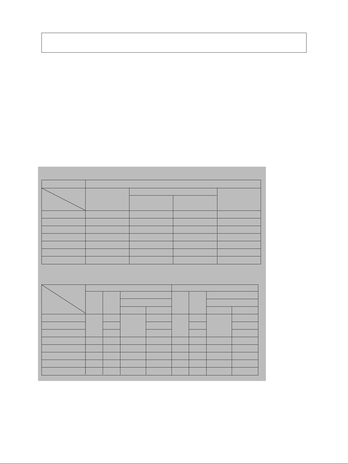
• Copy speed (For FC-22) (Copies/min.)
The same speed in both color and monochrome modes
Paper supply
Paper size
A4, LT
B5, A5-R, ST-R
A4-R, B5-R, LTR
B4, LG
A3, LD
OHP sheets (A4, LT)
Full bleed (12" x 18")
Cassette
22
22
17
14
12
4
–
Size specification
Bypass feeding
YES
18
18
15
14
12
4
12
Size specification
NO
12
12
12
12
12
–
12
LCF
22
–
–
–
–
–
–
• Copy speed (For FC-15) (Copies/min.)
Paper supply
Cassette
Paper size
A4
B5
A5-R
A4-R, B5-R
B4
A3
OHP sheets (A4)
A3 WIDE
January 2000 © TOSHIBA TEC 1 - 1 FC-22 SPECIFICATIONS
15
12
10
8
4
–
Color modes
LCF
15
–
–
–
–
–
–
–
SFB
Size specification
YES
15
12
10
8
4
8
NO
8
10
15
12
10
8
–
8
Cassette
Monochrome modes
LCF
22
22
17
14
12
–
–
–
–
–
4
–
–
–
SFB
Size specification
YES
18
15
14
12
4
12
NO
12
14
18
15
14
12
–
12
Page 3
The copy speed is the same in both color and black modes.
*
“–” shows “Not usable”.
*
The copy speeds listed are available when originals are manually placed for single-side, multiple
*
copying.
When the document feeder is used,
*
(1) FC-22
the copy speed of 22 sheets per minute is only avilable under the following conditions:
• Or iginal/Mode: Single-side originals of A4/LT size, not select auto color, APS,
automatic density and advance image enhancement mode
• Number of sheets set: 22 or over.
• Paper feeding: LCF
• Reproduction ratio: Actual ratio
(2) FC-15
the copy speed of 15 sheets per minute is only avilable under the following conditions:
• Or iginal/Mode: Single-side originals of A4/LT size, not select auto color, APS,
automatic density and advance image enhancement mode
• Number of sheets set: 15 or over.
• Paper feeding: LCF
• Reproduction ratio: Actual ratio
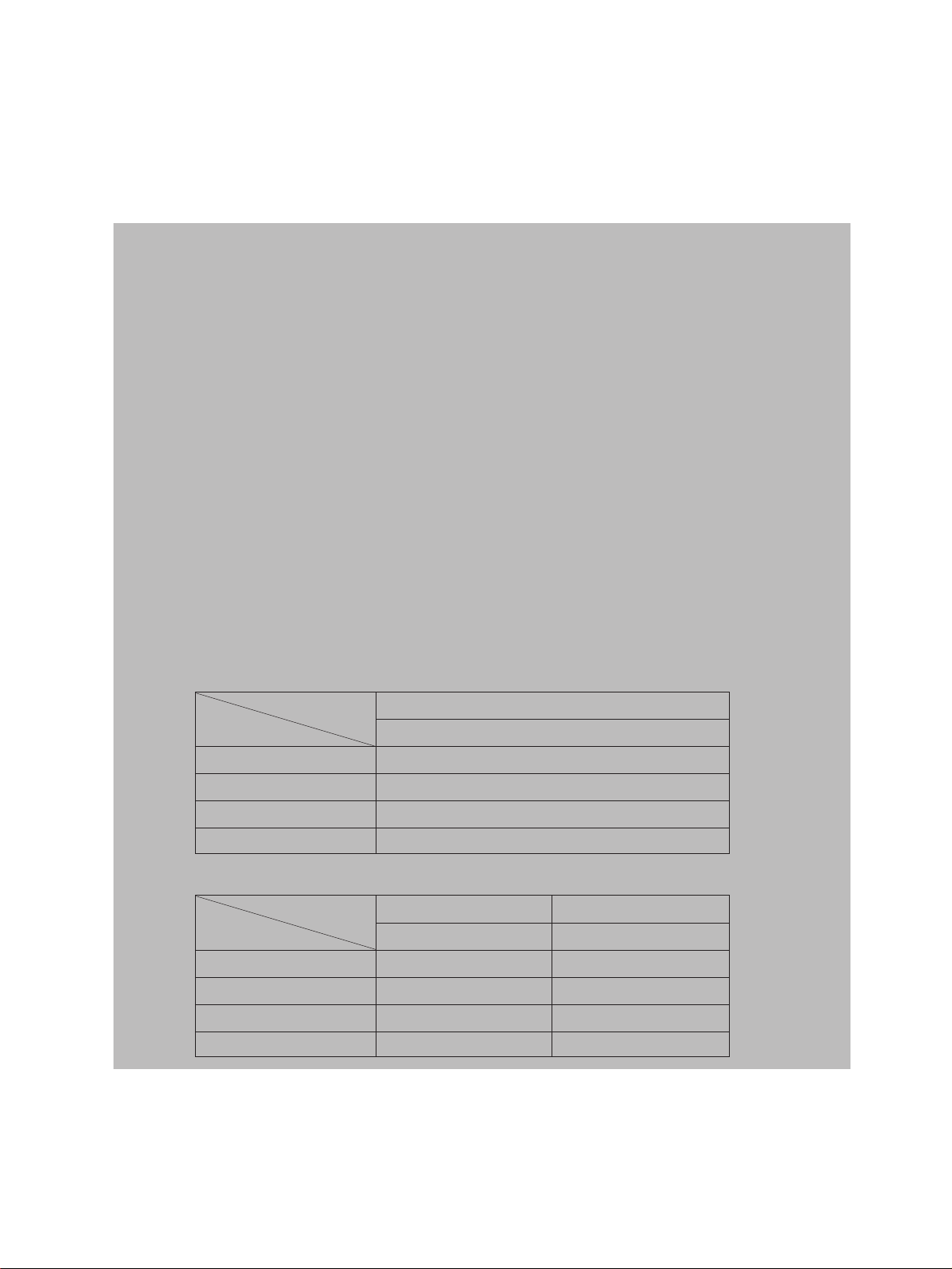
Reverse side copying speed of the automatic duplexing unit
*
(When specific paper size is selected)
For FC-22
Copy mode
Paper size
A4, B5, A5-R 22
A4-R, B5-R 17
B4 14
A3 12
For FC-15
Copy mode
Paper size
A4, B5, A5-R 15 22
A4-R, B5-R 12 17
B4 10 14
A3 8 12
The same speed in both color and monochrome modes
Color modes Monochrome modes
Copies/min. Copies/min.
Copies/min.
January 2000 © TOSHIBA TEC 1 - 1 - 1 FC-22 SPECIFICATIONS
Page 4
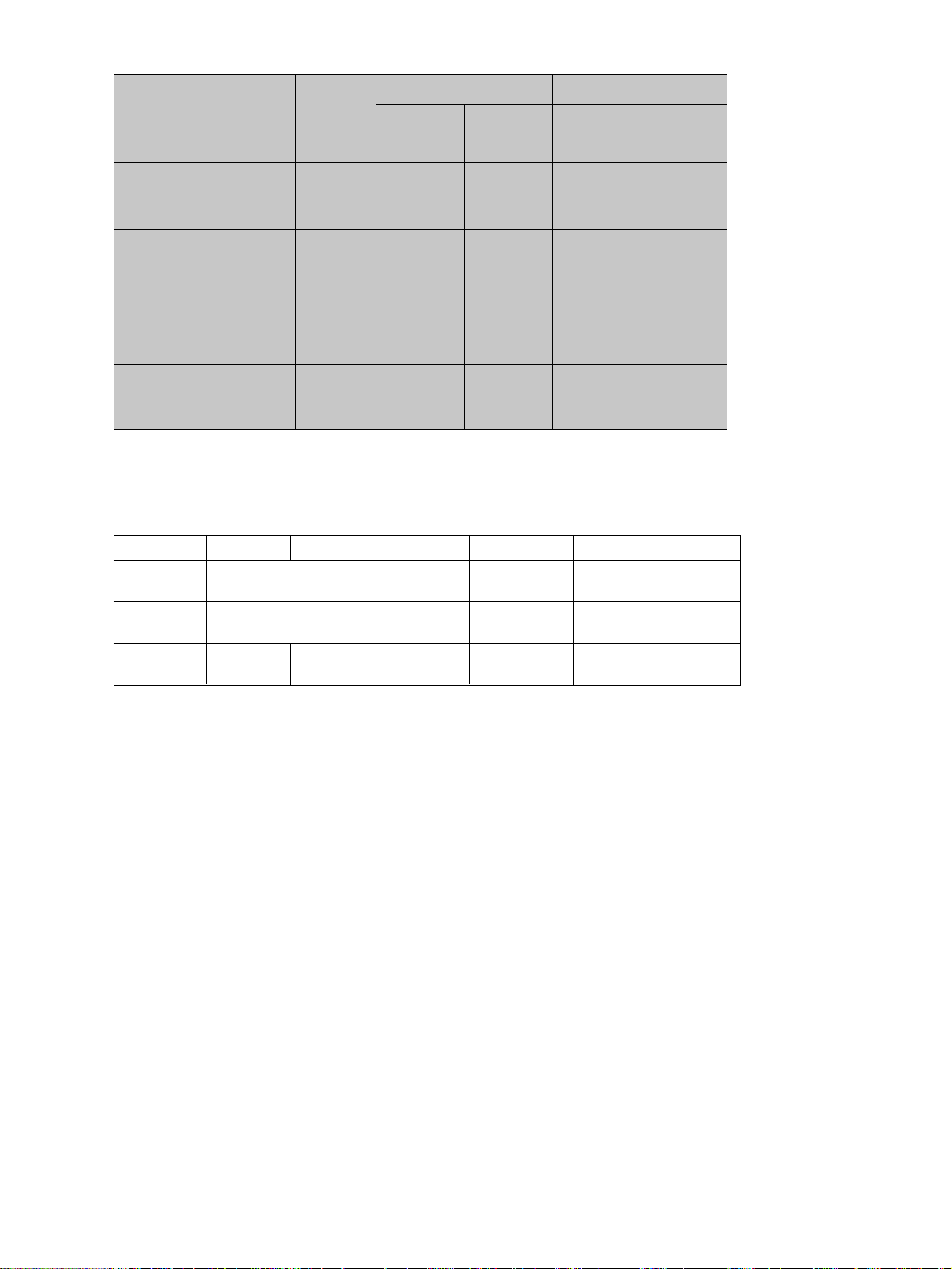
System copy speed
*
FC-15 FC-22
Copy mode
Number of
sheets set
Color modes
Monochrome
modes
The same speed in both color
and monochrome modes
Copies/min.Copies/min. Copies/min.
Single-sided originals 1 set 12 16 16
훹 3 sets 14 19 19
Single-sided copies 5 sets 14 20 20
Single-sided originals 1 set 4 4 4
훹 3 sets 8 9 9
Two-sided copies 5 sets 10 12 12
Two-sided originals 1 set 4 4 4
훹 3 sets 8 9 9
Two-sided copies 5 sets 10 12 12
Two-sided originals 1 set 11 12 12
훹 3 sets 13 17 17
Single-sided copies 5 sets 14 19 19
Any of the left copy speeds includes the first cop y time and is available when the corresponding copy
*
mode is used and 10 A4-sized originals are set in the automatic document feeder.
These values are attained in full color mode copying.
*
• Copy paper
Cassette Duplex copy LCF Bypass copy Remarks
Size A3~A5R A4, LT A3~A5-R Irregular or
LD~ST-R LD~ST-R arbitrary sizes can be set.
Weight 64~90g/m
Special paper – – – Recommended
2
, 17~24 lb. 64~209g/m
17~110 lb. index
OHP film
2
• First copy time .................. Approx. 10 seconds or under (A4/LT, the first cassette, 100%)
• Warming-up time...............Approx. 9 minutes
• Multiple copying ................ Up to 999 copies;entry by digital keys
• Reproduction ratio............. Actual ratio: 100±0.5%
Zooming: 25~400% in increments of 1%
• Resolution/Gradation Read: 600 dpi/256 gradation
Write: Corresponding to 9600 dpi x 600 dpi
(primary scanning only : 16 division smoothing)
• Excluded image width Leading edge: 5.0±2.0 mm, Trailing edge: 2.5±2.0 mm
Side edge: 2.0±2.0 mm
• Paper feeding .................... Automatic feeding: Copier’s cassettes–2 pieces standard (expandable up
to 4 pieces by installing optional cassettes)
LCF–Optional (Stack height 165 mm : Equivalent to 1500
sheets of 80 g/m2, 20 lb.)
Bypass feeding:
(Stack height 8 mm : Equivalent to 50 sheets of 80 g/m
• Capacity for originals .......................................A4, A4-R, B5, B5-R, A5-R, LT, LT-R, ST-R:
2
, 20 lb.)
50 sheets
(Optional automatic document feeder) B4, Folio, LG, Comp: 35 sheets
A3, LD: 25 sheets
FC-22 SPECIFICATIONS 1 - 2 January 2000 © TOSHIBA TEC
Page 5

2. PREVENTIVE MAINTENANCE (PM)
2. 1 Types of Preventive Maintenance
The following two types of preventive maintenance should be performed:
(1) General maintenance
General maintenance should be performed based on the value of the PM counter (08-857).
This maintenance, which covers the black developer unit as well as the entire machine, should be
conducted in conjunction with the replacement cycle (For FC-22: every 30K Copies, For FC-15:
every 20K Copies) of the black developer material.
(2) Color maintenance
Color maintenance should be performed based on the value of the color PM counter (08-897).
This maintenance, which is performed with a focus on the color developer units, should be conducted in conjunction with the replacement cycle of the color developer materials.
FC-22: every 30K copies
FC-15: every 20K copies
The replacement cycle (counter value) of color maintenance is determined by the ratio of color cop y
to black copy, as shown by the following table, "Variation in PM cycles due to color/black output
ratios".
Variation in PM cycles due to color/black output ratios
Color modes
100% 0% 20.0K 20.0K 30.0K 30.0K
90% 10% 20.0K 22.2K 30.0K 33.3K
80% 20% 20.0K 25.0K 30.0K 37.5K
70% 30% 20.0K 28.5K 30.0K 42.9K
60% 40% 20.0K 33.3K 30.0K 50.0K
50% 50% 20.0K 40.0K 30.0K 60.0K
*Therefore, replacing parts, cleaning and coating oil for the paper feeding unit, scanner unit, trans-
fer/transport unit, fuser unit, all should be checked and maintained in conjunction with the replacement cycle of the black developer material.
e.g. )Replacing fuser rollers : At the 3rd cycle of replacing black developer material
Replacing the transfer belt : At the 4th cycle of replacing black developer material
Monochrome FC-15 FC-22
modes PM (copies)
(30K × 3 = 90K copies)
Color PM (copies)
PM (copies)
Color PM (copies)
(30K × 4 = 120K copies)
*For the details of maintenance items, refer to the checklist described later.
*Yields are based on factory defaults.
January 2000 © TOSHIBA TEC 2 - 1 FC-22 PREVENTIVE MAINTENANCE
Page 6

2. 2 Maintenance to be Performed
FC-22: Every 30,000, 60,000, 90,000 and 120,000 Copies
FC-15: Every 20,000, 40,000, 60,000 and 80,000 Copies
(1) Preparation
1 Discuss current machine conditions with the key operator and note them down.
2 Before star ting maintenance, make a few sample copies by TCC-1 chart and save them for
later reference purposes.
3 Turn OFF the power switch, and be sure to unplug the copier.
(2) Perf orm pre v entiv e maintenance following the checklist shown below. During maintenance, refer to
the illustrations attached and the Service Manual as required.
(3) After having finished the maintenance, plug in the copier , turn ON the power switch, and mak e a few
copies to confirm that the copier is working normally.
2. 3 Preventive Maintenance Checklist
Symbols used in the checklist (For FC-22)
Cleaning Coating Replacing Operation check Date
A Cleaning with alcohol
Z Cleaning with soft pad,
cloth or vacuum cleaner
W White grease
(Molycoat)
AV Alvania No.2
30 Every 30K copies
60 Every 60K copies
90 Every 90K copies
120 Every 120K
copies
> Replace if
deformed or
damaged
Z After cleaning
or replacing,
check for no
abnormality.
User’s name
Serial No.
Inspector’s
name
Remarks
Symbols used in the checklist (For FC-15)
Cleaning Coating Replacing Operation check Date
A Cleaning with alcohol
Z Cleaning with soft pad,
cloth or vacuum cleaner
FC-22 PREVENTIVE MAINTENANCE 2 - 2 January 2000 © TOSHIBA TEC
W White grease
(Molycoat)
AV Alvania No.2
20 Every 20K copies
40 Every 40K copies
60 Every 60K copies
80 Every 80K copies
> Replace if
deformed or
damaged
Z After cleaning
or replacing,
check for no
abnormality.
User’s name
Serial No.
Inspector’s
name
Remarks
Page 7

General Maintenance Checklist FC-22
Section Item to inspect
1. Developer material 30 ∗9
2. Doctor blade Z(30/60) > ∗1
3. Developer unit drum seal Z(60) > ∗10
4. Front/rear sides of developer unit Z(60) ∗2
5. Oil seal portion AV
6. Cleaning blade 60 ∗3
7. Recovery blade Z(60) > ∗4
8.
Felt seals on both ends of the cleaning blade
Processing
unit (EPU)
(Only Black
related parts)
Around-EPU
area 22. Toner bag 30
Fuser unit
9. Entire developer/cleaner unit Z(60) ∗8
10. Main charger case Z(60) ∗7
11. Dischiarge LED Z(60)
12. Wire cleaning pad 60 Z
13. Main charger wire 60 ∗7
14. Main charger grid 60
15. Main charger contact Z(60)
16. Drum 60 ∗5
17. Drum shaft Z(60)
18. Drum thermister Z(60)
19. Toner recovery auger drive Z(60) W
20. Toner cartridge drive gear W
21. Ozone filter 60 ∗6
23. Upper fuser roller 90 ∗11
24. Lower fuser roller 90 ∗12
25. Separation fingers 90 ∗14
26. Upper oil roller 30 ∗13
27. Upper cleaning roller 30 ∗13
28. Lower oil roller 90 ∗13
29. Lower cleaning roller 90 ∗13
30. Upper thermistors A(30) >
31. Lower thermistors A(30) >
32. Fuser roller inlet guide A(90)
33. Fuser roller exit guide A(90)
34. Paper exit roller A
Cleaning Coating
Z(60) >
Replace every
1K copies
Operation Remarks
check <P-1>
<P23-I13>
<P22-I21>
<P22-I15>
<P22-I24>
<P22-I38>
<P6-I37>
Key-operator’s
item
<P33-I33>
<P27-I17>
<P27-I4>
<P28-I31>
<P28-I56>
<P28-I57>
<P28-I11>
<P28-I12>
January 2000 © TOSHIBA TEC 2 - 3 FC-22 PREVENTIVE MAINTENANCE
Page 8

W
Replace every
1K copies
Section Item to inspect
Image quality 35. Image quality sensor’s area Z(60)
control
Color 36. Color registration sensor Z(60)
registration
Laser unit 37. Slit glass Z(60)
38. Pick-up roller 90
39. Feed roller >
40. Separation roller >
41. Bypass pick-up roller 90
Paper feeding
system 43. Bypass separation pad A 90>
Scanner 54. Reflector Z(60)
Transfer/ 63. Drive roller cleaning felt 120
transport unit 64. Transfer belt cleaning blade 120
(TBU) 65. Transfer belt recovery blade Z(120)
42. Bypass feed roller
44. Registration roller A >
45. Paper guide Z(60) >
46. Paper dust brush Z(60) >
47.
Paper feeding system drive gears (tooth face)
48. Registration unit support bushings W
49. Original glass
50. Platen cover
51. Mirror 1 Z(60)
52. Mirror 2 Z(60)
53. Mirror 3 Z(60)
55. Lens Z(60)
56. Exposure lamp > Z
57. Original-width indicator Z
58. Automatic original detection unit Z
59. Slide sheet >
60. Air filter Z(60) >
61. Transfer belt 120
62. Transfer roller (Y, M, C, K) 120
66. Transfer belt drive roller Z(60) >
67. Transfer belt driven roller Z(60) >
Cleaning
Z(60)or A
Z(60)or A
Coating
Operation
check <P-1>
Remarks
<P14-I13>
<P17-I32>
<P17-I10>
<P30-I2>
<P30-I22>
<P30-I27>
<P30-I46>
FC-22
Notes: 1.<P-I> in the “Remarks” column indicates a page item in the Parts List.
2. The replacement cycle of each supply item of a particular paper feeding system corresponds with the
maximum number of sheets specified for the paper feed source.
FC-22 PREVENTIVE MAINTENANCE 2 - 4 January 2000 © TOSHIBA TEC
Page 9

Color Maintenance Checklist FC-22
Section Item to inspect
1. Developer material (Y, M, C) 30 ∗9
2. Doctor blade Z(30/60) > ∗1
3. Developer unit drum seal Z(60) > ∗10
4. Front/rear sides of developer unit Z(60) ∗2
5. Oil seal portion AV
6. Cleaning blade 60 ∗3
7. Recovery blade Z(60) > ∗4
8.
Felt seals on both ends of the cleaning blade
Processing
unit (EPU)
(Color (Y, M,
C) related
parts)
Image quality 35. Image quality sensor’s area Z(60)
control
Color 36. Color registration sensor Z(60)
registration
Laser unit 37. Slit glass Z(60)
9. Entire developer/cleaner unit Z(60) ∗8
10. Main charger case Z(60) ∗7
11. Dischiarge LED Z(60)
12. Wire cleaning pad 60 Z
13. Main charger wire 60 ∗7
14. Main charger grid 60
15. Main charger contact Z(60)
16. Drum 60 ∗5
17. Drum shaft Z(60)
18. Drum thermister Z(60)
19. Toner recovery auger drive Z(60) W
Cleaning Coating
Z(60) >
Replace every
1K copies
Operation Remarks
check <P-1>
<P23-I13>
<P22-I21>
<P22-I15>
<P22-I24>
<P22-I38>
Note: 1.<P-I> in the “Remarks” column indicates a page item in the Parts List.
January 2000 © TOSHIBA TEC 2 - 5 FC-22 PREVENTIVE MAINTENANCE
Page 10

General Maintenance Checklist FC-15
Section Item to inspect
1. Developer material (Y, M, C) 20 ∗9
2. Doctor blade Z(20/40) > ∗1
3. Developer unit drum seal Z(40) > ∗10
4. Front/rear sides of developer unit Z(40) ∗2
5. Oil seal portion AV
6. Cleaning blade 40 ∗3
7. Recovery blade Z(40) > ∗4
8.
Felt seals on both ends of the cleaning blade
Processing
unit (EPU)
(Only Black)
related
parts)
Processing
unit Around
EPU area
Fuser unit
9. Entire developer/cleaner unit Z(40) ∗8
10. Main charger case Z(40) ∗7
11. Dischiarge LED Z(40)
12. Wire cleaning pad 40 Z
13. Main charger wire 40 ∗7
14. Main charger grid 40
15. Main charger contact Z(40)
16. Drum 40 ∗5
17. Drum shaft Z(40)
18. Drum thermister Z(40)
19. Toner recovery auger drive Z(40) W
20. Toner cartridge drive gear W
21. Ozone filter 40 ∗6
22.
Toner bag 30
23. Upper fuser roller 60 ∗11
24. Lower fuser roller 60 ∗12
25. Separation fingers 60 ∗14
26. Upper oil roller 20 ∗13
27. Upper cleaning roller 20 ∗13
28. Lower oil roller 60 ∗13
29. Lower cleaning roller 60 ∗13
30. Upper thermistors A(20) >
31. Lower thermistors A(20) >
32. Fuser roller inlet guide A(60)
33. Fuser roller exit guide A(60)
34. Paper exit roller A
Cleaning Coating
Z(40) >
Replace every
1K copies
Operation Remarks
check <P-1>
<P23-I13>
<P22-I21>
<P22-I15>
<P22-I24>
<P22-I38>
<P6-I37>
Key-operator’s
item
<P33-I33>
<P27-I17>
<P27-I4>
<P28-I31>
<P28-I56>
<P28-I57>
<P28-I11>
<P28-I12>
January 2000 © TOSHIBA TEC 2 - 5 - 1 FC-22 PREVENTIVE MAINTENANCE
Page 11

FC-15
W
Replace every
1K copies
Section Item to inspect
Image quality 35. Image quality sensor’s area Z(40)
control
Color 36. Color registration sensor Z(40)
registration
Laser unit 37. Slit glass Z(40)
38. Pick-up roller 90
39. Feed roller >
40. Separation roller >
41. Bypass pick-up roller 90
Paper feeding
system 43. Bypass separation pad A 90>
Scanner 54. Reflector Z(40)
Transfer/ 63. Drive roller cleaning felt 80
transport unit 64. Transfer belt cleaning blade 80
(TBU) 65. Transfer belt recovery blade Z(80) >
42. Bypass feed roller
44. Registration roller A >
45. Paper guide Z(40) >
46. Paper dust brush Z(20) >
47.
Paper feeding system drive gears (tooth face)
48. Registration unit support bushings W
49. Original glass
50. Platen cover
51. Mirror 1 Z(40)
52. Mirror 2 Z(40)
53. Mirror 3 Z(40)
55. Lens Z(40)
56. Exposure lamp > Z
57. Original-width indicator Z
58. Automatic original detection unit Z
59. Slide sheet >
60. Air filter Z(40) >
61. Transfer belt 80
62. Transfer roller (Y, M, C, K) 80
66. Transfer belt drive roller Z(40) >
67. Transfer belt driven roller Z(40) >
Cleaning
Z(40)or A
Z(40)or A
Coating
Operation
check <P-1>
Remarks
<P14-I13>
<P17-I32>
<P17-I10>
<P30-I2>
<P30-I22>
<P30-I27>
<P30-I46>
Notes: 1.<P-I> in the “Remarks” column indicates a page item in the Parts List.
2. The replacement cycle of each supply item of a particular paper feeding system corresponds with the
maximum number of sheets specified for the paper feed source.
January 2000 © TOSHIBA TEC 2 - 5 - 2 FC-22 PREVENTIVE MAINTENANCE
Page 12

Color Maintenance Checklist FC-15
Section Item to inspect
1. Developer material (Y, M, C) 20 ∗9
2. Doctor blade Z(20/40) > ∗1
3. Developer unit drum seal Z(40) > ∗10
4. Front/rear sides of developer unit Z(40) ∗2
5. Oil seal portion AV
6. Cleaning blade 40 ∗3
7. Recovery blade Z(40) > ∗4
8.
Felt seals on both ends of the cleaning blade
Processing
unit (EPU)
(Color (Y, M,
C) related
parts)
Image quality 35. Image quality sensor’s area Z(40)
control
Color 36. Color registration sensor Z(40)
registration
Laser unit 37. Slit glass Z(40)
9. Entire developer/cleaner unit Z(40) ∗8
10. Main charger case Z(40) ∗7
11. Dischiarge LED Z(40)
12. Wire cleaning pad 40 Z
13. Main charger wire 40 ∗7
14. Main charger grid 40
15. Main charger contact Z(40)
16. Drum 40 ∗5
17. Drum shaft Z(40)
18. Drum thermister Z(40)
19. Toner recovery auger drive Z(40) W
Cleaning Coating
Z(40) >
Replace every
1K copies
Operation Remarks
check <P-1>
<P23-I13>
<P22-I21>
<P22-I15>
<P22-I24>
<P22-I38>
Note: 1.<P-I> in the “Remarks” column indicates a page item in the Parts List.
January 2000 © TOSHIBA TEC 2 - 5 - 3 FC-22 PREVENTIVE MAINTENANCE
Page 13

2. 4 PM Kit
Kit name Classification of kits Part name Q'ty
DEV-KIT-FC22
(30K kit)
EPU-KIT-FC22
(60K kit)
FU-KIT-FC22 25. Separation finger SCRAPER-PR 9
(90K kit) 28. Lower oil roller SR-FC22L 1
TBU-KIT-FC22 62. Transfer roller CR-FC22TR 4
(120K kit) 63. Drive roller cleaning felt FP-FC22TR 1
No. of copies for
replacement cycle
1. Developer material (Y) PS-ZDFC22Y 1
1. Developer material (M) PS-ZDFC22M 1
1. Developer material (C) PS-ZDFC22C 1
1. Developer material (K) PS-ZDFC22K 1 30K
26. Upper oil roller (fuser unit) SR-FC22H 1
27. Upper cleaning roller (fuser unit) B-FC22H 1
– Doctor blade cleaning jig
6. Cleaning blade BL-FC22D 4
12. Charger wire cleaning pad WIRE-CH-310 4
13. Main charger wire K-PAD-WIRE 4 60K
14. Main charger grid GRID-CH-310 4
21. Ozone filter K-FILTER-OZN 1
23. Upper fuser roller HR-FC22-U 1
24. Lower fuser roller HR-FC22-L 1
29. Lower cleaning roller B-FC22L 1
38. Pick-up roller (cassette feed section)
61. Transfer belt BT-FC22TR 1
64. Transfer belt cleaning blade BL-FC22TR 1
JIG-CLEAN-DOC
K-ROL-PICK-310
1
90K
1
120K
FC-22
* The numbers in the “Classification of kits” column above correspond with the numbers in the
Preventive Maintenance Checklist.
FC-22 PREVENTIVE MAINTENANCE 2 - 12 January 2000 © TOSHIBA TEC
Page 14

PM Kit
Kit name Classification of kits Part name Q'ty
1. Developer material (Y) PS-ZDFC22Y 1
1. Developer material (M) PS-ZDFC22M 1
DEV-KIT-FC22
(20K kit)
EPU-KIT-FC22
(40K kit)
FU-KIT-FC22 25. Separation finger SCRAPER-PR 9
(60K kit) 28. Lower oil roller SR-FC22L 1
TBU-KIT-FC22 62. Transfer roller CR-FC22TR 4
(80K kit) 63. Drive roller cleaning felt FP-FC22TR 1
1. Developer material (C) PS-ZDFC22C 1
1. Developer material (K) PS-ZDFC22K 1 20K
26. Upper oil roller (fuser unit) SR-FC22H 1
27. Upper cleaning roller (fuser unit) B-FC22H 1
– Doctor blade cleaning jig
6. Cleaning blade BL-FC22D 4
12. Charger wire cleaning pad WIRE-CH-310 4
13. Main charger wire K-PAD-WIRE 4 40K
14. Main charger grid GRID-CH-310 4
21. Ozone filter K-FILTER-OZN 1
23. Upper fuser roller HR-FC22-U 1
24. Lower fuser roller HR-FC22-L 1
29. Lower cleaning roller B-FC22L 1
39. Pick-up roller (cassette feed section)
61. Transfer belt BT-FC22TR 1
64. Transfer belt cleaning blade BL-FC22TR 1
JIG-CLEAN-DOC
K-ROL-PICK-310
FC-15
No. of copies for
replacement cycle
1
60K
1
80K
* The numbers in the “Classification of kits” column above correspond with the numbers in the
Preventive Maintenance Checklist.
FC-22 PREVENTIVE MAINTENANCE 2 - 12 -1 January 2000 © TOSHIBA TEC
 Loading...