

Page 1
BSINo. G00F053 Page 1
BSI No.: G00F053
Publish
2000/06/19
Date:
Subject: Connection Change of Switching Power Supply Fan Harness when
KR-7038 (X3e) is Installed
Model: FC22
Category Field Application UNIT
Other countermeasures To be applied when necessary Optional Kit
FactoryApplication: BF080082
CONTENT
When the internal controller (KR-7034:X3e) is installed in the FC22, the load of the switching power
supply becomes heavier. In that case when the front cover and the paper-exit cover are opened, the
power supply fan must be operated.
[Changed Contents]
Presently when fan operation is stropped by opening by the covers, there is a problem with the
temperature of the switching power supply board rising when the covers are opened. So, to operate
the fan when the covers are opened, the power supply fan controller has been changed from the door
type 24V to the main type 24V.
* Cover open: when the front cover and the paper-exit cover are opened
* The connector place of the switching power supply fan is changed.
: The connector on the switching power supply -> The connector for the LGC board
[Important]
Applied for machines up to May
z
When the front cover or the paper-exit cover is opened, the fan operation stops. Change based on
the attached file "G00F053.pdf".
"Changed method of harness" has been applied from June at the factory (BF080082).
z
Attached File
G00F053.pdf
Related Documents:
LinkTo: Link From:
Page 2
1. Remove the harness of the power supply fan
(1) Remove the rear cover. (9 screws)
(2) Remove the harness of the power supply fan.
Pull out the harness of the power supply fan from CNF (printed silk) connector on the
board of the switching power supply.
(3) Remove the connecting harness which is connected to J 126 on the LGC board.
4406565690 WH-PS-FAN- 310
Remove the harness of
The connector of
WH-PS-FAN-310
the power supply fan
from the CNF connector....
Remove the connecting
harness (WH-PS-FAN-310)
from the M clamp.
Page 3

2. Connect with the harness of the power supply and the connecting harness
Connect the harness of the removed power supply fan in 1 (2) above and the removed
connecting harness from the M clamp in 1 (3). To prevent any imperfect connection, make
sure that it is inserted securely.
Connect firmly
Page 4

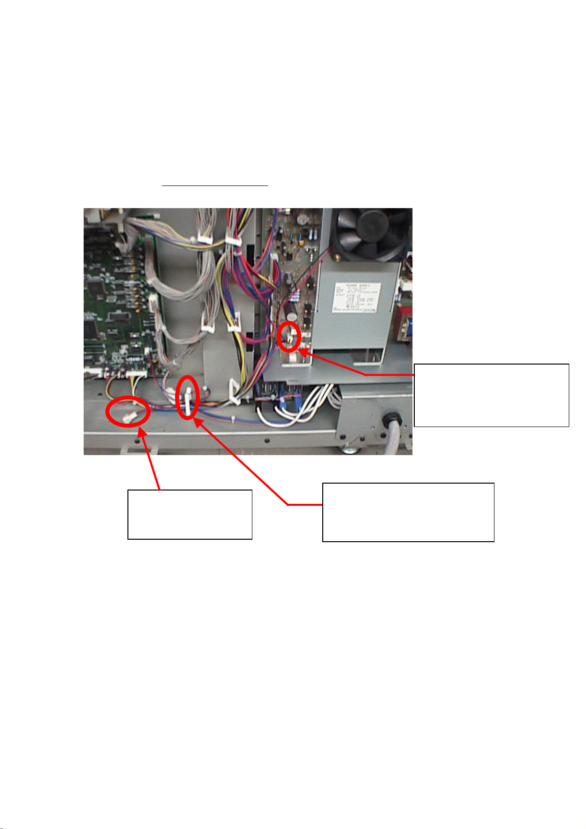
3. Connect the harness
A
(1) The harness connected in 2 above should be connected by passing M clamps (3
places) in the order A -> B -> C as shown by the circles in the photograph.
(2) After connecting the M clamps, check that none of the LGC board connections have
become loose.
(3) Install the rear cover (9 screws).
Be careful not to catch the harness.
BC
Connect the M
clamp (3 places)
Check the LGC board connection
 Loading...