

Page 1
BSINo. G00B945 Page 1
BSI No.: G00B945
Publish
2000/02/29
Date:
Subject: Change of Part and Developer Agent Automatic Discharge Structure
Model: FC22
Category Field Application UNIT
Change of Parts To be applied when necessary Developer
FactoryApplication: From Mar. 2000
CONTENT
In the case of automatic discharge of the developer material, sometimes the discharge shutter
cannot be opened or closed.
C33 error (abnormality in the operation of the developer material discharge shutter)
The alignment of the gears driving the developer material discharge shutter is shallow and
occasionally the gears will jump. This countermeasure is to make the alignment normal.
This change corresponds to machines assembled from Number BA010311; those before are
not included. For machines which have not had this countermeasure applied, when a C33
error happen, using [the assembly instructions] below, carry out adjustment. However, if the
part change below is made, this adjustment is unnecessary.
[Assembly instruction]
1. Machine
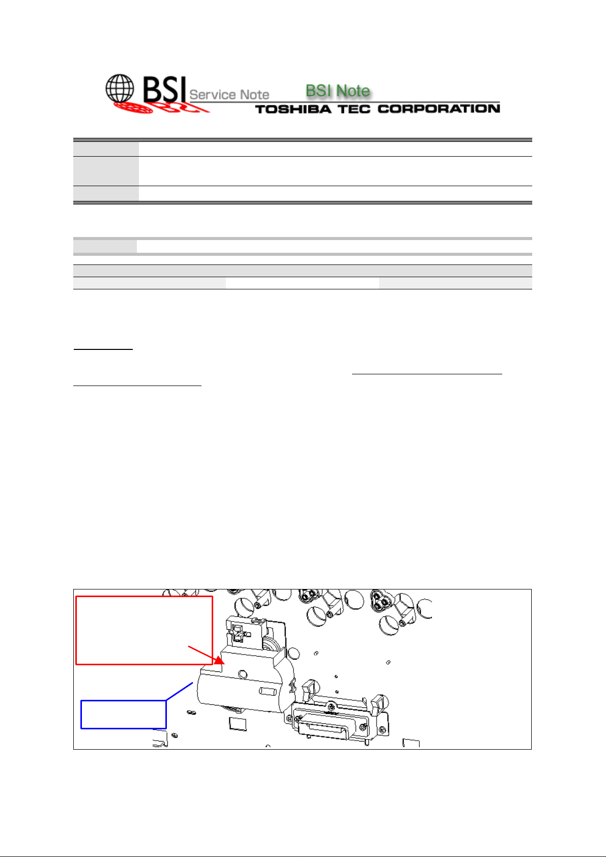
If you open the front cover and remove the EPU unit, then as shown in the figure below, you will be
able to check whether the developer material discharge shutter opening and closing unit is attached
to the rear frame or not.
This unit is fixed to the upper part of the rear frame by one 3mm screw and 3 dowel diameter in one
place.
Developer material discharge
shutter opening and closing
unit
Rear frame
Page 2
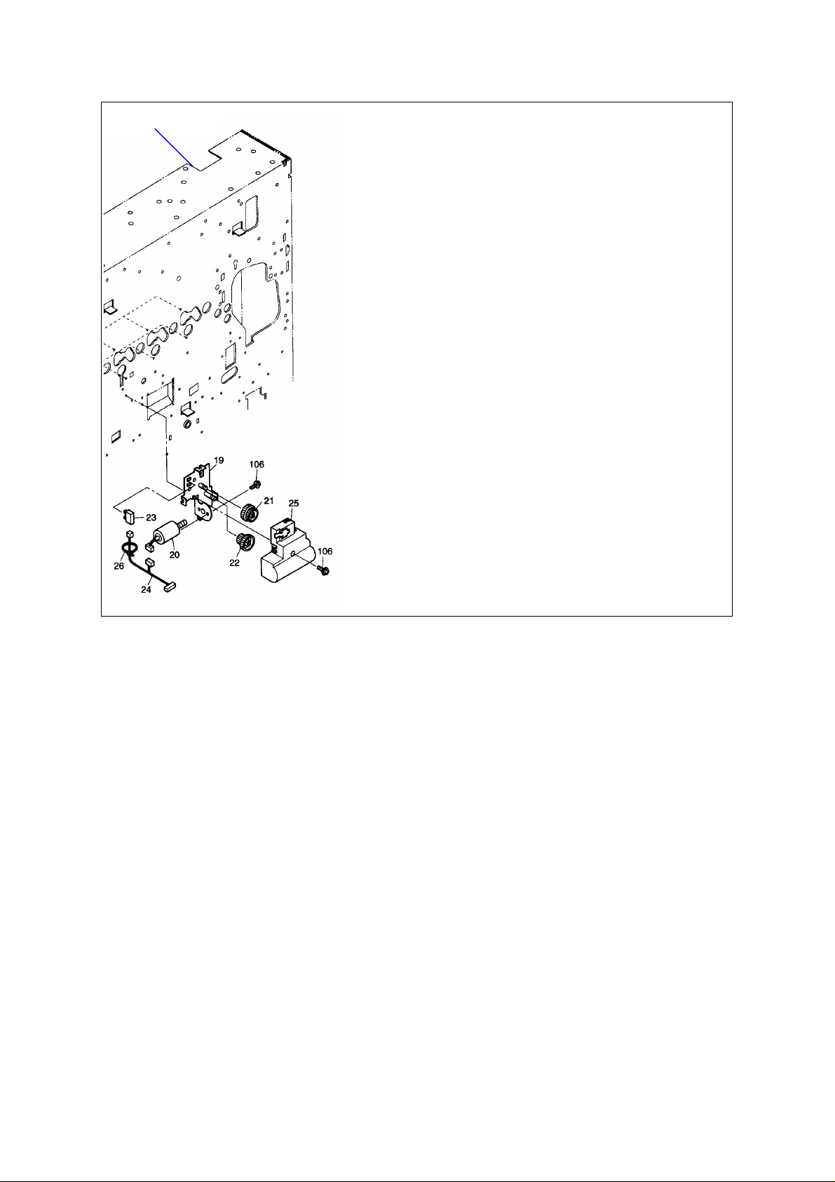
Rear frame
BSINo. G00B945 Page 2
Carry out adjustment as follows.
Page 3

BSINo. G00B945 Page 3
direction.
Procedure
1. Temporarily fix a screw is not the center of the 3mm screw hole. Turn dowel playing clockwise
until it is projected.
2. Fix the drive unit with 3mm screws.
3. Check that the dowel has not come out from the hole in the figure on the right.
Note: Check that the
frame dowel has not
removed itself from the
Rotate the center of the M3
screw hole in a clockwise
hole and that it has not
come upon to drive unit.
M3 screw hole
(Rotation center)
2. EPU side
Adjust the opening/closing spring in the figure below.
Opening/closing spring
Page 4

BSINo. G00B945 Page 4
From the U-turn hook, adjust the upper
side so that there are at least 27 winding.
(1)
by pulling the spring in the direction of the arrow.
Pull the lower side of the opening/closing spring which is hanging in a U shape in the direction of the
arrow (1). Adjust the upper side so that there are at least 27 winding.
(2)
U-turn
hook
Make sure that there is a gap for the spring of the upper side
The following parts have been applied from March at the factory. If this change is applied, no
assembly change is necessary.
[Changed/Added Parts No.]
MODEL P-I Before Change After Change Note P I R
FC-22 7-19
7-21
4406531550
K-BRKT-DRV-DEV
4406531620
GG10S024/08S035
4406531560
K-BRKT-DRV-DEV
4406531650
GG10S024/08S035
3mm hole
diameter added
Change of teeth
thickness:
5mm -> 6.5mm
C B E Y
C B E Y
FAA
Attached File
Related Documents:
LinkTo: Link From:
 Loading...