

Page 1

GENERAL PRECA UTIONS REGARDING THE INSTALLATION
AND SERVICE FOR THE COPIER FC-22
The installation and service should be done by a qualified service technician.
1. Transportation/Installation
• When transporting/installing the copier, move it by the casters while lifting the stoppers.
The copier is quite heavy and weighs approximately 200 kg (441 lb), therefore pay full attention
when handling it.
• Be sure to use a dedicated outlet with AC 115V or 120V/20A (220V, 230V , 240V/10A) or more for
its power source.
• The copier must be grounded for safety.
Never ground it to a gas pipe or a water pipe.
• Select a suitable place for installation.
Avoid excessive heat, high humidity, dust, vibration and direct sunlight.
• Also provide proper ventilation as the copier emits a slight amount of ozone.
• To insure adequate working space for the copying operation, keep a minimum clearance of
80 cm (32”) on the left, 80 cm (32”) on the right and 10 cm (4”) in the rear.
2. Service of Machines
• Basically, be sure to turn the main switch off and unplug the power cord during service.
• Be sure not to touch high-temperature sections such as the exposure lamp, the fuser unit, the
damp heater and their periphery.
• Be sure not to touch high-voltage sections such as the chargers, the transfer belt and the highvoltage transformer.
• Be sure not to touch rotating/operating sections such as gears, belts, pulleys, fan, etc.
• When servicing the machines with the main switch turned on, be sure not to touch live sections
and rotating/operating sections. Avoid exposure to laser radiation.
• Use suitable measuring instruments and tools.
• Avoid exposure to laser radiation during servicing.
− Avoid direct exposure to the beam.
− Do not insert tools, parts, etc. that are reflective into the path of the laser beam.
− Remove all watches, rings, bracelets, etc. that are reflective.
3. Main Service Parts for Safety
• The breaker, door switch, fuse, thermostat, thermofuse, thermistor, etc. are particularly important for safety. Be sure to handle/install them properly.
4. Cautionary Labels
• During servicing, be sure to check the rating plate and the cautionary labels such as “Unplug the
power cord during service”, “Hot area”, “Laser warning label” etc. to see if there is any dirt on
their surface and whether they are properly stuck to the copier.
Page 2

5. Disposition of Consumable Parts/Packing Materials
• Regarding the recovery and disposal of the copier, supplies, consumable par ts and packing
materials, it is recommended to follow the relevant local regulations or rules.
6. When parts are disassembled, reassembly is basically the reverse of disassembly unless
otherwise noted in this manual or other related documents. Be careful not to reassemble
small parts such as screws, washers, pins, E-rings, star washers in the wrong places.
7. Basically, the machine should not be operated with any parts removed or disassembled.
8. Precautions Against Static Electricity
• The PC board must be stored in an anti-electrostatic bag and handled carefully using a wrist-
band, because the ICs on it may become damaged due to static electricity.
Caution: Before using the wristband, pull out the power cord plug of the copier and make
sure that there are no uninsulated charged objects in the vicinity.
Caution : Dispose of used RAM-ICs (including lithium battery)
according to the manufacturer’s instr uctions.
Vorsicht : Entsorgung des gebrauchten RAM-ICs (inklusive
der Lithium-Batterie) nach Angaben des Herstellers.
Page 3

1. ADJUSTMENT ITEMS
2. PREVENTIVE MAINTENANCE
(PM)
3. PRECAUTIONS FOR STORING
& HANDLING SUPPLIES
4. TROUBLESHOOTING
5. FIRMWARE UPDATING
6. WIRE HARNESS CONNECTION
DIAGRAMS
Page 4

CONTENTS
1. ADJUSTMENT ITEMS ............................................................................................................... 1-1
1.1 Error Code List....................................................................................................................... 1-1
1.2 Self Diagnostic Mode............................................................................................................. 1-6
1.2.1 Input check (Test mode 03) ...................................................................................... 1-8
1.2.2 Output check (Test mode 03) ................................................................................... 1-15
1.2.3 Test print mode (04).................................................................................................. 1-19
1.2.4 Adjustment mode (05) .............................................................................................. 1-20
1.2.5 Setting mode (08) ..................................................................................................... 1-33
1.2.6 Registering/changing ID codes................................................................................. 1-43
1.3 Adjustment Order (Copy Image Related Adjustment)............................................................ 1-45
1.4 A utomatic Adjustment of the Auto-Toner Circuit..................................................................... 1-46
1.5 Automatic Initialization of Image Quality Control ................................................................... 1-50
1.6 Copy Image Dimensional Adjustment.................................................................................... 1-51
1.6.1 Paper alignment (paper buckle) at the main registration roller ................................. 1-53
1.6.2 Feed motor speed adjustment.................................................................................. 1-54
1.6.3 Printer related adjustment ........................................................................................ 1-55
1.6.4 Scanner related adjustment...................................................................................... 1-58
1.7 A utomatic Adjustment of Gamma Correction......................................................................... 1-66
1.8 Density Adjustment ................................................................................................................ 1-68
1.9 Color Balance Adjustment...................................................................................................... 1-69
1.10 Offset Amount for Processing Background............................................................................ 1-70
1.11 Judgment Threshold for ACS ................................................................................................. 1-71
1.12 AI Mode Setting ..................................................................................................................... 1-72
1.13 Sharpness Adjustment........................................................................................................... 1-73
1.14 High-Voltage Transformer Setting .......................................................................................... 1-74
1.14.1 Overview................................................................................................................... 1-74
1.14.2 Settings after replacing main high-voltage transformers .......................................... 1-74
1.14.3 Settings after replacing transfer transformer ............................................................ 1-75
1.15 Adjusting Doctor-to-Sleeve Gap ............................................................................................ 1-76
1.16 Adjusting the Scanner Section............................................................................................... 1-77
1.16.1 Adjusting the carriage ............................................................................................... 1-77
1.16.2 Lens unit ................................................................................................................... 1-80
1.17 Adjusting the Cassette for Sidewise Deviation ...................................................................... 1-83
1.18 Key Copy Counter (MU-8, MU-10)......................................................................................... 1-84
2. PREVENTIVE MAINTENANCE (PM) ......................................................................................... 2-1
2.1 Types of Preventive Maintenance .......................................................................................... 2-1
2.2 Maintenance to be Performed Every 30,000, 60,000, 90,000 and 120,000 Copies .............. 2-2
2.3 Preventive Maintenance Checklist ......................................................................................... 2-2
2.4 PM Kit .................................................................................................................................... 2-12
I January 2000 © TOSHIBA TECFC-22 CONTENTS
Page 5

2.5 List of Adjustment Tools ......................................................................................................... 2-13
3. PRECAUTIONS FOR STORING & HANDLING SUPPLIES ...................................................... 3-1
3.1 Precautions for Storing TOSHIBA Supplies ........................................................................... 3-1
3.2 Checking and Cleaning of the Photoconductive Drum .......................................................... 3-1
3.3 Checking and Cleaning of the Drum Cleaning Blade and Transfer Belt Cleaning Blade ....... 3-2
3.4 Checking and Replacing the Oil Roller and Cleaning Roller of Fuser Section ...................... 3-3
3.5 Checking and Cleaning of the Fuser Rollers ......................................................................... 3-3
3.6 Checking and Replacing the Transfer Belt ............................................................................. 3-4
3.7 Checking and Replacing the Transfer Roller.......................................................................... 3-4
4. TROUBLESHOOTING................................................................................................................ 4-1
4.1 Troubleshooting Based on Error Code ................................................................................... 4-1
4.1.1 Paper transport jam inside the copier ....................................................................... 4-1
4.1.2 Paper feeding jam..................................................................................................... 4-3
4.1.3 Paper transport jam (Paper not reaching the registration sensor after feeding)....... 4-5
4.1.4 Cover open jam ........................................................................................................ 4-6
4.1.5 Paper jam in ADU and reversing area ...................................................................... 4-8
4.1.6 Original jam in the RADF.......................................................................................... 4-10
4.1.7 Paper jam in the sorter ............................................................................................. 4-12
4.1.8 Special sheet jam ..................................................................................................... 4-15
4.1.9 Drive system related service call .............................................................................. 4-16
4.1.10 Paper feeding system related service call ................................................................ 4-20
4.1.11 Scanner related service call ..................................................................................... 4-23
4.1.12 Copy process related service call ............................................................................. 4-25
4.1.13 Fuser unit related service call................................................................................... 4-30
4.1.14 Communications related service call ........................................................................ 4-33
4.1.15 ADF related service call............................................................................................ 4-36
4.1.16 Other service calls .................................................................................................... 4-37
4.1.17 Laser optical unit related service call........................................................................ 4-38
4.1.18 Sorter related service call ......................................................................................... 4-40
4.1.19 Image quality related service call ............................................................................. 4-45
4.1.20 Options related service call ...................................................................................... 4-52
4.1.21 Image processing options related service call.......................................................... 4-53
4.2 Troubleshooting of Image....................................................................................................... 4-54
5. FIRMWARE UPDATING............................................................................................................. 5-1
5.1 [3] [9] Mode Operation ........................................................................................................... 5-1
5.1.1 Outline ...................................................................................................................... 5-1
5.1.2 Preparation of PC ..................................................................................................... 5-1
5.1.3 Firmware update operation....................................................................................... 5-4
IIJanuary 2000 © TOSHIBA TEC FC-22 CONTENTS
Page 6

5.1.4 Screen details........................................................................................................... 5-10
5.2 Installation Instructions for Firmware Update through PC ..................................................... 5-14
5.2.1 Outline ...................................................................................................................... 5-14
5.2.2 System configuration ................................................................................................ 5-14
5.2.3 Preparation of PC to use a network.......................................................................... 5-15
5.2.4 Installation of FTP server.......................................................................................... 5-25
6. WIRE HARNESS CONNECTION DIAGRAMS .......................................................................... 6-1
6.1 AC Wire Harness ................................................................................................................... 6-1
6.2 DC Wire Harness.......................................................................................................... Appendix
III January 2000 © TOSHIBA TECFC-22 CONTENTS
Page 7
In this manual, colors are sometimes described using abbreviations as listed below:
Yellow : Y Magenta : M Cyan : C Black : K
1. ADJUSTMENT ITEMS
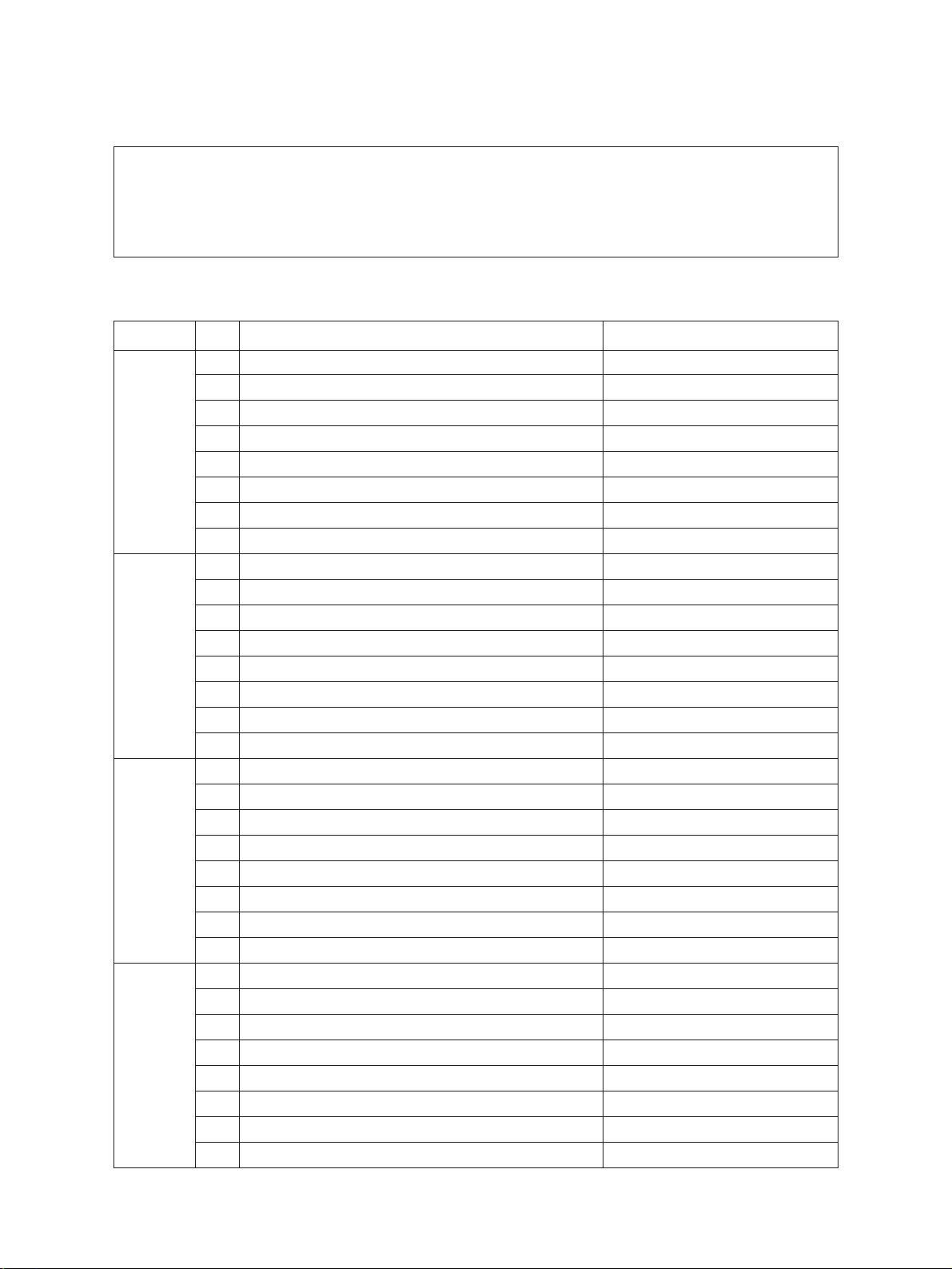
1.1 Error Code List
While the “CLEAR PAPER” or “CALL SERVICE” symbol is flashing, pressing the [CLEAR] key and
the [8] key on the digital keys at the same time shows one of the following error codes on the copyquantity indicator as long as those keys are pressed.
Classification
Paper transport jam inside the copier
Paper feeding jam E11 Paper misfeed from the ADU
Paper transport jam
(Paper not reaching the registration
sensor after feeding)
Cover open jam E41 Front cover opened during copying
Paper jam in ADU and reversing
area
Error code
E01 Paper leading edge not reaching the exit sensor
E02 Paper trailing edge not passing the exit sensor
E03 Paper remaining inside the copier at power ON
EB7 Restart time out error
E12 Paper misfeed from the bypass
E13 Paper misfeed from the 1st cassette
E14 Paper misfeed from the 2nd cassette
E15 Paper misfeed from the 3rd cassette
E16 Paper misfeed from the 4th cassette
E19 Paper misfeed from the LCF
E21 Paper transport jam from the LCF
E22 Paper transport jam from the 1st cassette
E23 Paper transport jam from the 2nd cassette
E24 Paper transport jam from the 3rd cassette
E25 Paper transport jam from the 4th cassette
E42 Side door opened during copying
E43 ADU unit pulled out during copying
E45 LCF jam access cover opened during copying
E46 Bypass unit opened during copying
E50 Paper not reaching the ADU
E51 Paper not restarting from the ADU stack
E52 Paper not reaching the ADU path sensor
E54 ADU paper transport jam
Content
January 2000 © TOSHIBA TEC 1 - 1 FC-22 ADJUSTMENT
Page 8
Classification
Error code
Content
Original jam in the ADF E71 Original not reaching the aligning sensor
E72 Original not reaching the exit sensor
E73 Original not passing the exit sensor
E75
Second original not reaching the aligning sensor in 2-in-1 mode
E79 Original pre-feeding jam
Paper jam in the sorter EA1 Paper transport delay jam
EA2 Paper transport stop jam
EA3 Paper remaining on the sorter transport path at power on
EA4 Sorter front door opened during copying
EA5 Staple jam
Paper jam in the sorter EA6 Finisher/sorter early-arrival jam (P30) (internal)
EA8 Finisher saddle staple jam
EA9 Finisher saddle door open
EAA Finisher saddle power ON jam
EAB Finisher saddle delivery delay
EAC Finisher saddle delivery failure
Special sheet jam EC2 OHP sheets used except from bypass and 2nd cassette
EC3 OHP sheet used in non-OHP mode
Drive system related service call C05 ADU motor rotation abnormal
Paper feeding system related
service call
Scanner related service call C27
C09 Black developer motor rotation abnormal
C0A Color developer motor rotation abnormal
C0B Drum motor K rotation abnormal
C0C Drum motor C rotation abnormal
C0D Drum motor M rotation abnormal
C0E Drum motor Y rotation abnormal
C11 ADU paper side guide function abnormal
C12 ADU paper end guide function abnormal
C13 1st cassette tray function abnormal
C14 2nd cassette tray function abnormal
C15 3rd cassette tray function abnormal
C16 4th cassette tray function abnormal
C18 LCF tray function abnormal
Carriage home position sensor not turning OFF within a fixed time
C28
Carriage home position sensor not turning ON within a fixed time
C29 Exposure lamp disconnection detected
FC-22 ADJUSTMENT 1 - 2 January 2000 © TOSHIBA TEC
Page 9

Classification
Copy process related service call C31 Used toner transport motor rotation abnormal
Error code
C33 Developer removal shutter function abnormal
C35 Transfer belt unit contact/release function abnormal
C37 Transfer belt moter rotation abnormal
C38 Auto toner initializing error (K)
C39 Auto toner initializing error (C)
C3A Auto toner initializing error (M)
C3B Auto toner initializing error (Y)
C3C Main charger wire abnormal (K)
C3D Main charger wire abnormal (C)
C3E Main charger wire abnormal (M)
C3F Main charger wire abnormal (Y)
Content
January 2000 © TOSHIBA TEC 1 - 2 - 1 FC-22 ADJUSTMENT
Page 10
Classification
Fuser unit related service call C41
Communications related service call C57 Communications error between Main-CPU and Sorter-CPU
Error code
Thermistor or heater abnormal when warming-up is started
C42 Thermistor abnormal after the copier becomes ready
C43 Thermistor abnormal during warming-up after abnormality
judgment
C44 Heater abnormal during warming-up after abnormality
judgment
C46 Heater abnormal (low temperature) after the copier has
become ready
C47 Rear thermistor abnormal after the copier has become
ready
C48 Heater abnormal (high temperature)
C7 Error C7
C5A
C5B Main-CPU signal transmission error to IMC-CPU
C5C Main-CPU signal reception error from IMC-CPU
Communications error between Main-CPU and printer controller
Content
ADF related service call C72 Error of aligning sensor automatic adjustment
C73 EEPROM initializing error
C74 Error of paper exit sensor automatic adjustment
Other service calls C94 Main-CPU abnormal
C9A Main memory abnormal
C9E IMC board connection abnormal
Laser optical unit related service call
CA1 Polygonal motor rotation abnormal
CA2 H-SYNC abnormal
CD1 Laser calibration error (K)
CD2 Laser calibration error (C)
CD3 Laser calibration error (M)
CD4 Laser calibration error (Y)
January 2000 © TOSHIBA TEC 1 - 3 FC-22 ADJUSTMENT
Page 11
Classification
Sorter related service call CB1 Delivery motor abnormal
Sorter related service call
Error code
CB2 Paper exit motor abnormal
CB3 Tray-up motor abnormal
CB4 Alignment motor abnormal
CB5 Staple motor abnormal
CB6 Staple unit shift motor abnormal
CB7 Stack detection sensor abnormal
CB8 Backup RAM data abnormal
CB9 Saddle push motor abnormal
CBA Saddle outer staple motor abnormal
CBB Saddle inner staple motor abnormal
CBC Saddle alignment motor abnormal
CBD Saddle guide motor abnormal
CBE Saddle folding motor abnormal
CBF Saddle positioning plate motor abnormal
CC0 Sensor connector connection abnormal
CC2 Micro-switch abnormal
Content
CC1 Transport motor rotation abnormal
CC3 Bin shift motor rotation abnormal
CC4 Guide bar swing motor rotation abnormal
CC5 Staple-unit swing motor rotation abnormal
CCA Automatic adjustment error of bin inside paper sensor
CCC No power being supplied
Image quality related service call CE1 Image quality sensor abnormal (OFF level)
CE2 Image quality sensor abnormal (no pattern level)
CE3 Abnormal image caused by poor charger
CE4 Image quality control test pattern abnormal
CE5 Temperature/humidity sensor upper-limit abnormal
CF1 Color registation control abnormal
January 2000 © TOSHIBA TEC 1 - 3 - 1 FC-22 ADJUSTMENT
Page 12

Classification
Options related service call F07 Communications error between System-CPU and Main-CPU
Image processing options related
service call
Error code
F11
Communications error between System-CPU and Scanner-CPU
Content
F51 Communications error between System-CPU and AI-board
during pre-scanning
FC-22 ADJUSTMENT 1 - 4 January 2000 © TOSHIBA TEC
Page 13
<<Error history>>
Under code 253 in the setting mode (08), the latest eight groups of error data will be displayed.
Display example
EA1 99 08 26 17 57 32 64 64 236210000000
Error code
3 digits 12 digits 3 digits 3 digits 12 digits
A Paper source
0:Not fixed 1:Bypass feed 2:LCF 3:1st 4:2nd 5:3rd 6:4th 7:ADU feed
B Paper size code
0:A5/ST 1:A5-R 2:ST-R 3:LT 4:A4 5:B5-R 6:LT-R 7:A4-R 8:OTHER/UNIV 9:B5
A:FOL/COM B:LG C:B4 D:LD E:A3 Z:Not selected
YY MM DD HH MM SS
MMM NNN
ABCDEFHIJLOP
C Sort mode
0:Not selected 1:Group 2:Sort 6:Staple sort
D DF mode
0:Unused 1:AUTO FEED (SADF) 2:STACK FEED
E APS/AMS mode
0:Not selected 1:APS 2:AMS
F Duplex mode
0:Not selected 1:BOOK 2:T wo-sided/Single-sided 4:T wo-sided/Duple xed 8:Single-sided/Duplex ed
G Unused
H Binding space
0:Unused 1:BOOK 2:LEFT 4:RIGHT
I Editing
0:Unused 1:Masking 2:Trimming 3:Mirror image 4:Negative/Positive
J Edge erase/Dual-page
0:Unused 1:Edge erase 2:Dual-page 3:Edge erase & Dual-page
K Unused
L Function
0:Copying 1:Unused (Extended copying) 2:Unused (Fax input) 3:Unused (Fax printing)
4:Printing 5:Unused (DSS)
MMM Primary-scanning reproduction ratio (Display in hexadecimal)
(Mx256)+(Mx16)+M
NNN Secondary-scanning reproduction ration (Display in hexadecimal)
(Nx256)+(Nx16)+N
O Color mode
0:Auto color 1:Full color 2:Black 3:Monocolor
P AI board
0:Unused 1:Used
January 2000 © TOSHIBA TEC 1 - 5 FC-22 ADJUSTMENT
Page 14
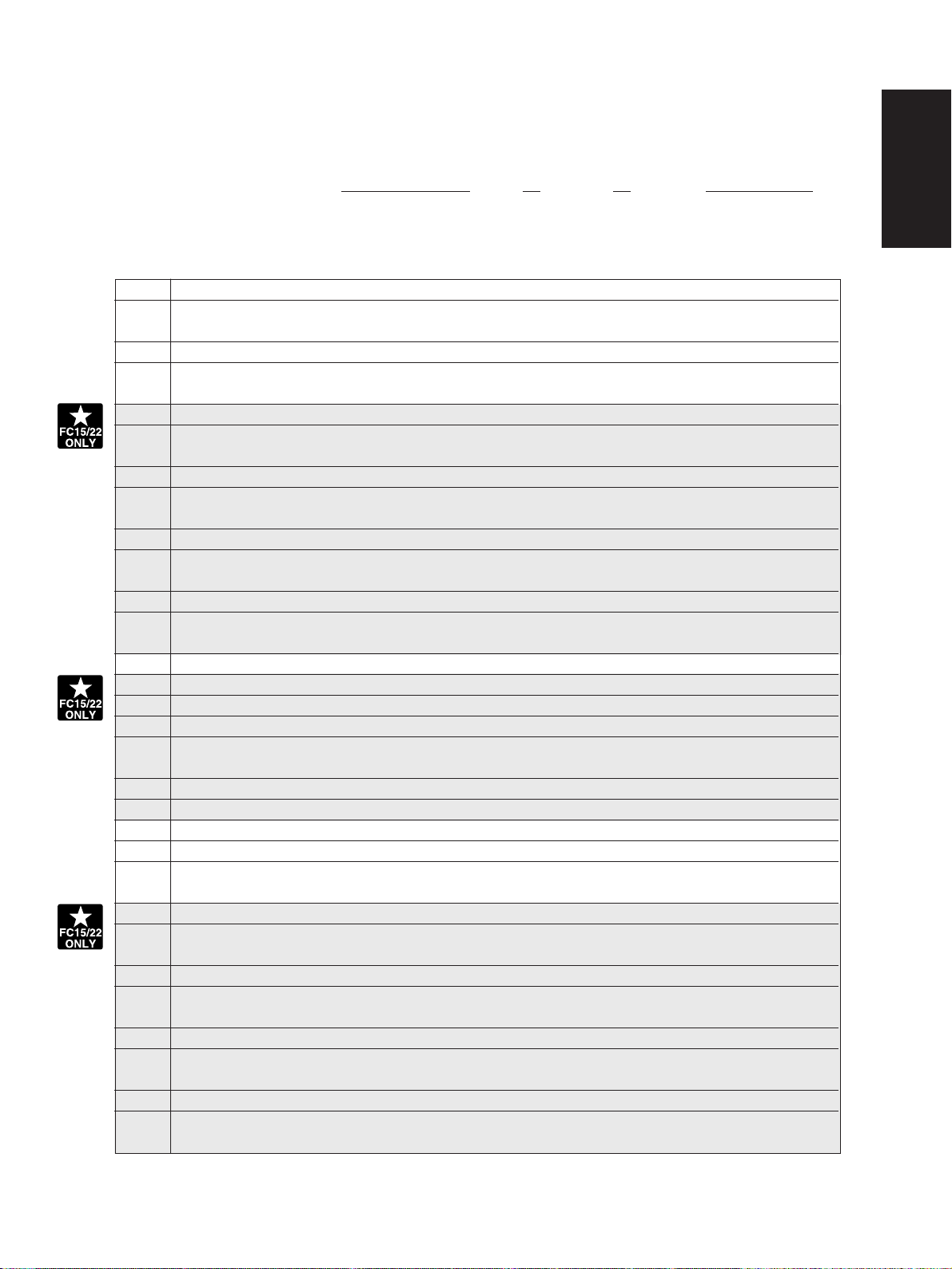
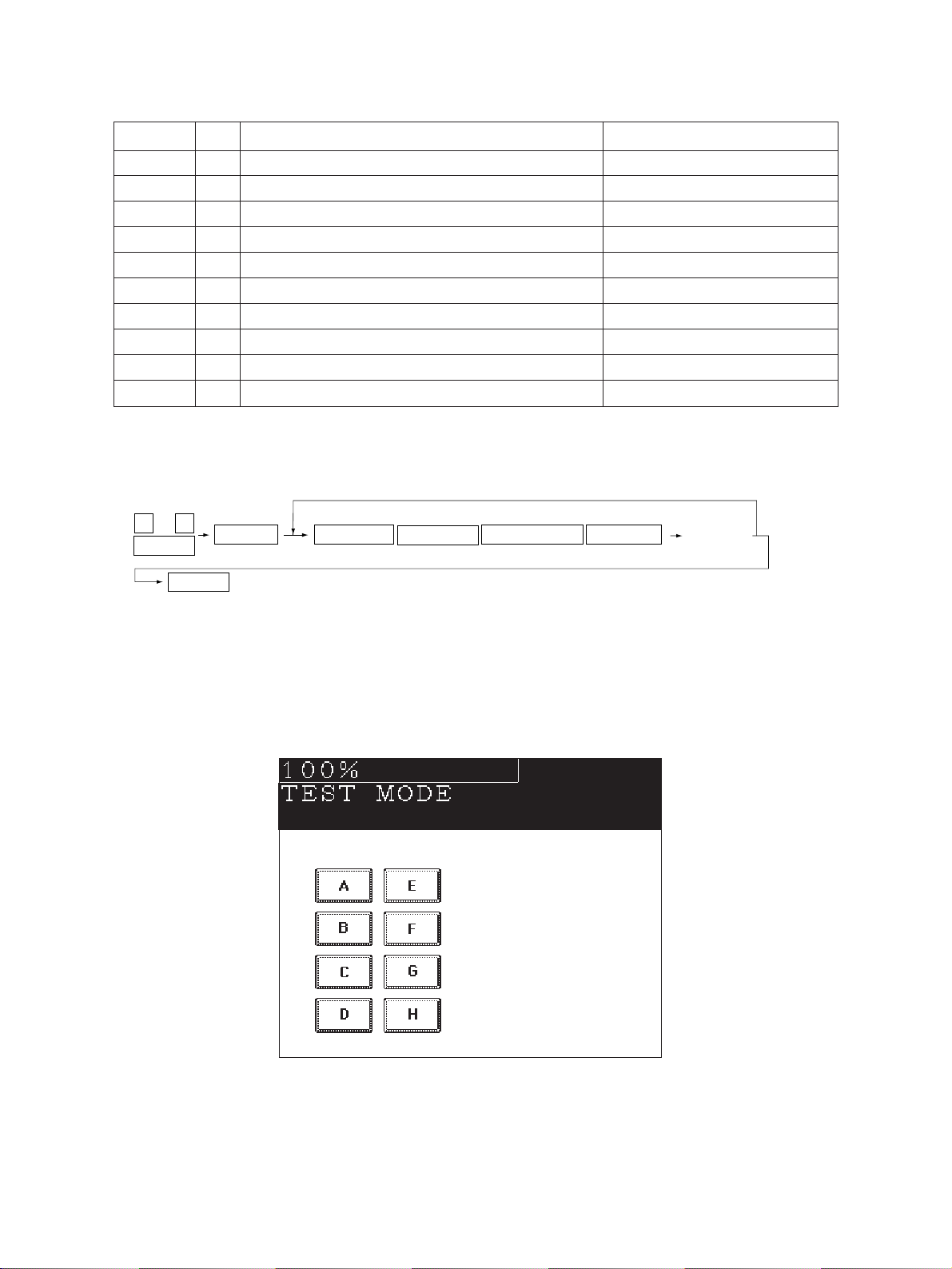
1. 2 Self Diagnostic Mode
Mode Input method Meaning Clearing
Whole control panel light-
[0]+[1]+[POWER]
ing mode
Test mode
Test print mode
Adjustment mode
Setting mode
[0]+[3]+[POWER]
[0]+[4]+[POWER]
[0]+[5]+[POWER]
[0]+[8]+[POWER]
Note: Input method for various modes:
While pressing simultaneously the two digital keys corresponding to the mode you want to set
(for example, [0] and [5]), turn on the main switch [POWER].
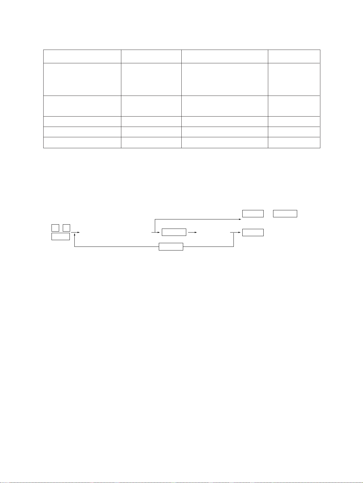
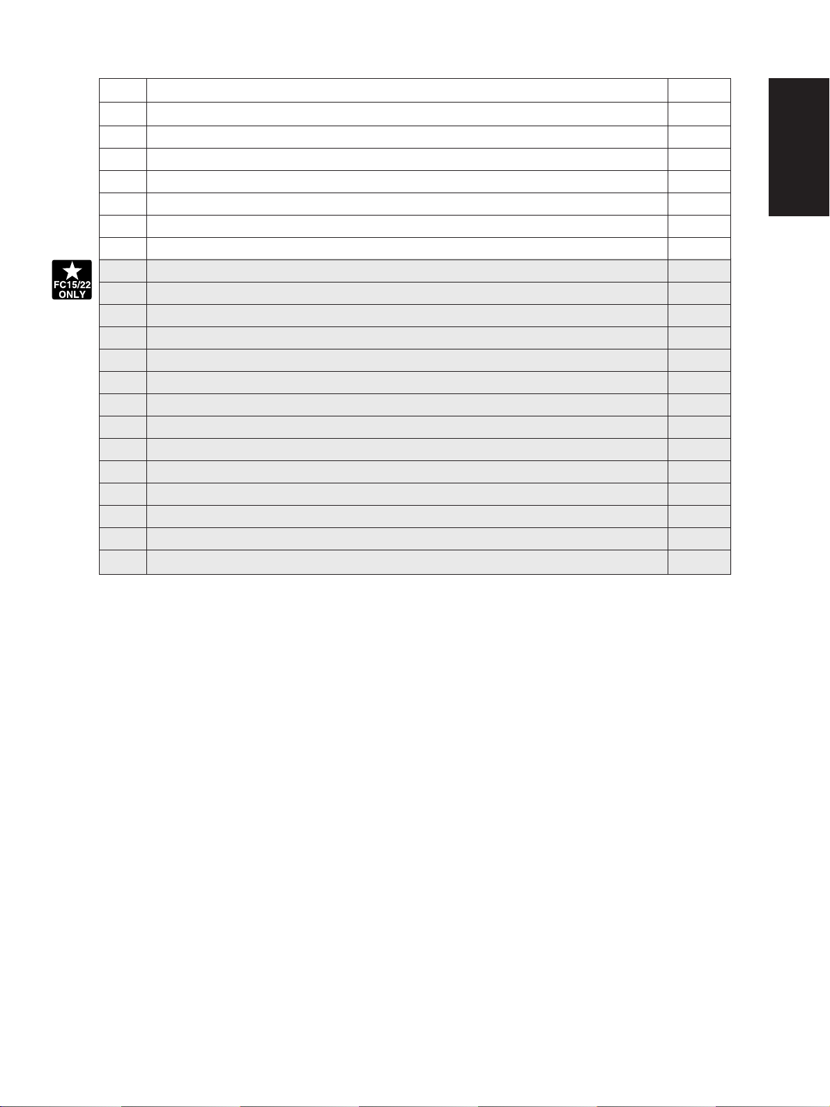
<Operation procedure>
0 1
Power
(All control-panel LEDs light)
START
START
All control-panel LEDs are lit,
and all LCD pixels are turned
on/off repeatedly.
Input/output signals are
checked
A test pattern print is made.
Adjustment of various items
Setting of various items
CLEAR
(Exit)
(Check Key)
CLEAR
(Exit)
[C] or [POWER]
OFF/ON
[POWER] OFF/ON
[POWER] OFF/ON
[POWER] OFF/ON
[POWER] OFF/ON
POWER OFF/ON
or
• Whole control-panel lighting mode (01) :
Notes: 1. During the “Check keys” mode, [CLEAR] alone can do.
During the “Whole control-panel lighting mode”, [CLEAR] can clear the mode.
2. Check keys : Any key with LED (when it is pressed, the LED goes out.)
Any key without LED (When it is pressed, an indication is made in the message area.)
• Test mode (03) :Refer to Sec. 1.2.1 and 1.2.2 for test modes.
• Test print mode (04) : Refer to Sec. 1.2.3 for test print modes.
• Adjustment mode (05) : Refer to Sec. 1.2.4 for adjustment modes.
• Setting mode (08) : Refer to Sec. 1.2.5 for setting modes.
FC-22 ADJUSTMENT 1 - 6 January 2000 © TOSHIBA TEC
Page 15
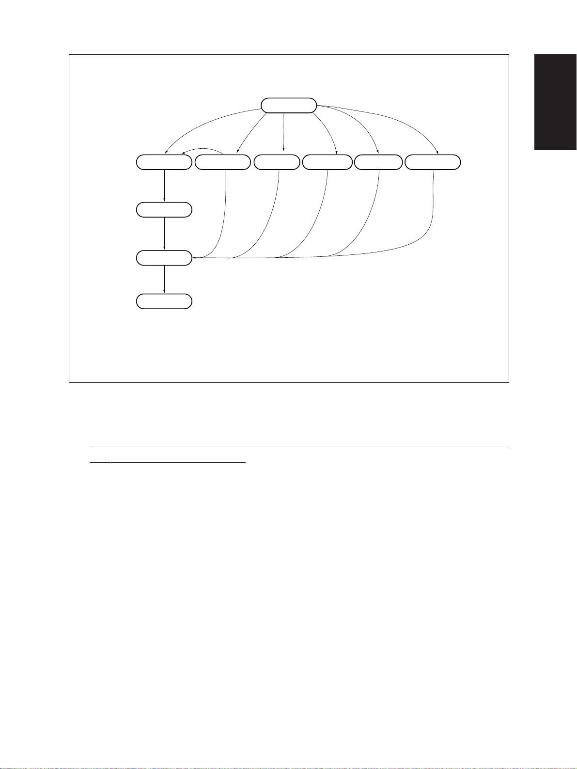
Normal
[CLEAR]
Warming up
Standby
[Power] OFF/ON
*2
Hand over to user
[Power] ON
[0][1]
*1
All the displays on
the control panel lit
[0][3] [0][5]
Test mode
Adjustment mode
[0][8]
[0][4]
Setting mode
Transition diagram of self-diagnostic mode conditions
Test print mode
*1 : During the “Whole control-panel lighting mode”, cop ying is not possible . But after pressing [CLEAR]
to make the copier ready, you can make copies.
*2 : After having used the self-diagnostic mode, be sure to turn OFF and then ON the power before
returning the copier to the customer.
January 2000 © TOSHIBA TEC 1 - 7 FC-22 ADJUSTMENT
Page 16
1. 2. 1 Input check (Test mode 03)
The status of each item can be checked by setting ON/OFF of each [FULL COLOR], [A UT O COLOR],
[ENERGY SAVER], and then pressing each of the corresponding digital key in this test mode 03.
Note: When icon is displa yed with b lack letter on white bac kground, it indicates the v alue is 0, while
in reverse black and white, it indicates the value is 1.
[FULL COLOR]key: OFF, [AUTO COLOR]key: OFF, [ENERGY SAVER]key: OFF
Digital key Icon Item Condition
A Paper size switch 0 (1st cassette : Lower) 0: Switch is ON
B Paper size switch 1 (1st cassette : Middle lower) 0: Switch is ON
C Paper size switch 2 (1st cassette : Middle upper) 0: Switch is ON
1 D Paper size switch 3 (1st cassette : Upper) 0: Switch is ON
E Cassette paper empty sensor (1st cassette) 1: No paper
F Cassette tray-up limit sensor (1st cassette) 1: Tray is upper limit
G Cassette-feed jam sensor (1st cassette) 1: Paper exist
H—
A Paper size switch 0 (2nd cassette : Lower) 0: Switch is ON
B Paper size switch 1 (2nd cassette : Middle lower) 0: Switch is ON
C Paper size switch 2 (2nd cassette : Middle upper) 0: Switch is ON
2
3
4
D Paper size switch 3 (2nd cassette : Upper) 0: Switch is ON
E Cassette paper empty sensor (2nd cassette) 1: No paper
F Cassette tray-up limit sensor (2nd cassette) 1: Tray is upper limit
G Cassette-feed jam sensor (2nd cassette) 1: Paper exist
H—
A Paper size switch 0 (3rd cassette : Lower) 0: Switch is ON
B Paper size switch 1 (3rd cassette : Middle lower) 0: Switch is ON
C Paper size switch 2 (3rd cassette : Middle upper) 0: Switch is ON
D Paper size switch 3 (3rd cassette : Upper) 0: Switch is ON
E Cassette paper empty sensor (3rd cassette) 1: No paper
F Cassette tray-up limit sensor (3rd cassette) 1: Tray is upper limit
G Cassette-feed jam sensor (3rd cassette) 1: Paper exist
H—
A Paper size switch 0 (4th cassette : Lower) 0: Switch is ON
B Paper size switch 1 (4th cassette : Middle lower) 0: Switch is ON
C Paper size switch 2 (4th cassette : Middle upper) 0: Switch is ON
D Paper size switch 3 (4th cassette : Upper) 0: Switch is ON
E Cassette paper empty sensor (4th cassette) 1: No paper
F Cassette tray-up limit sensor (4th cassette) 1: Tray is upper limit
G Cassette-feed jam sensor (4th cassette) 1: Paper exists
H—
FC-22 ADJUSTMENT 1 - 8 January 2000 © TOSHIBA TEC
Page 17
Digital key Icon Item Condition
A Bypass paper-width sensor 0 Refer to Table 1.
B Bypass paper-width sensor 1 Refer to Table 1.
C Bypass paper-width sensor 2 Refer to Table 1.
5
6 E LCF paper supply door switch 1: Door is open
7
8
D Bypass paper-width size sensor 3 Refer to Table 1.
E Bypass paper sensor 1: No paper
F Bypass unit open/close switch 1: Unit is open
G Side door open/close switch 1: Side door is open
H Bypass unit is installed or not 0: Unit is installed
A LCF paper empty sensor 1: No paper
B LCF lower-limit sensor 1: Tray limit (lower)
C LCF tray-up sensor 1: Tray limit (upper)
D LCF tray-down switch 0: Switch is ON
F LCF is installed or not 0: LCF is installed
G ADU motor rotation status 0: Normal rotation
(Motor is rotating by 03 Output mode)
H ADU unit is installed or not 0: ADU unit is installed
A ADU paper jam switch 1: Paper exist
B ADU paper empty switch 0: No paper
C ADU end switch 1:
D ADU side switch 1:
E—
F Total counter is installed or not 0: Total counter is installed
G Key copy counter is installed or not 0: Key copy counter is installed
H—
A Developer removal shutter home position sensor 0: Shatter is closed
B—
C Transfer belt unit is installed or not 0: Unit is installed
D—
E Color developer motor rotation status 0: Normal rotation
(Motor is rotating by 03 Output mode)
F Black developer motor rotation status 0: Normal rotation
(Motor is rotating by 03 Output mode)
G Transfer belt limit switch 0:
H Transfer belt home position switch 0:
End guide is positioned at home position
Side guide is positioned at home position
Transfer belt is blac k mode position
Transfer belt is color mode position
January 2000 © TOSHIBA TEC 1 - 9 FC-22 ADJUSTMENT
Page 18
Digital key Icon Item Condition
A External printer controller power ON/OFF 0: Controller power ON
B—
C—
9
0
D Front-cover switch 1: Front cover is open
E OHP center sensor 0: Opaque paper is installed
F—
G Registration sensor 1: Paper exist
H IPC-IF board (Sorter installation kit) is installed or not 0: Board installed
A ADU path sensor 1: Paper exist
B—
C Exit sensor 1: Paper exist
D Paper-exit unit open/close switch 1: Paper-exit unit is open
E Toner bag limit sensor 1: Used toner full
F—
G—
H—
Table 1. Relation between bypass paper-width sensor status and paper width size.
Bypass paper-width sensor
3210
0 1 1 1 A3/LD
1 0 1 1 A4-R/LT-R
1 1 0 1 A5-R/ST-R
1 1 1 0 Card size
0 0 1 1 B4-R/LG
1001B5-R
Paper-width size
FC-22 ADJUSTMENT 1 - 10 January 2000 © TOSHIBA TEC
Page 19

[FULL COLOR]key: OFF, [AUTO COLOR]key: OFF, [ENERGY SAVER]key: ON
Digital key Icon Item Condition
A—
B—
C—
1
2
3
4
D—
E—
F—
G—
H—
A Developer cartridge Y is installed or not 0: Cartirdge is installed
B Developer cartridge M is installed or not 0: Cartirdge is installed
C Developer cartridge C is installed or not 0: Cartirdge is installed
D Developer cartridge K is installed or not 0: Cartirdge is installed
E Processing unit is installed or not 0: Unit is installed
F Fuser unit is installed or not 0: Unit is installed
G—
H—
A Wire cleaner home position switch Y 0:
B Wire cleaner home position switch M 0:
C Wire cleaner home position switch C 0:
D Wire cleaner home position switch K 0:
E Wire cleaner limit switch Y 0:
F Wire cleaner limit switch M 0:
G Wire cleaner limit switch C 0:
H Wire cleaner limit switch K 0:
A—
B—
C—
D—
E—
F—
G—
H—
Cleaning pad is positioned at home position.
Cleaning pad is positioned at home position.
Cleaning pad is positioned at home position.
Cleaning pad is positioned at home position.
Cleaning pad is positioned at limit position.
Cleaning pad is positioned at limit position.
Cleaning pad is positioned at limit position.
Cleaning pad is positioned at limit position.
January 2000 © TOSHIBA TEC 1 - 11 FC-22 ADJUSTMENT
Page 20
Digital key Icon Item Condition
A—
B—
C—
5
6
7——
8 — Upper fuser roller thermistor (center) check
9 — Upper fuser roller thermistor (rear) check
0 — Lower fuser roller thermistor (center) check
D—
E—
F—
G—
H—
A—
B—
C—
D—
E—
F—
G Front cover, paper-exit unit open/close check 1: Cover/unit open
H
Polygonal motor rotation status (Motor is rotating by 03 Output mode)
0: Normal rotation
Thermistor output value is displayed with 8 bit.
Thermistor output value is displayed with 8 bit.
Thermistor output value is displayed with 8 bit.
[FULL COLOR]key: OFF, [AUTO COLOR]key: ON, [ENERGY SAVER]key: OFF
Digital key Icon Item Condition
1 — Lower fuser roller thermistor (rear) check
2 — Temperature sensor check
3 — Humidity sensor check
4 — Drum thermistor Y check
5 — Drum thermistor M check
6 — Drum thermistor C check
7 — Drum thermistor K check
8——
9——
0——
Thermistor output value is displayed with 8 bit.
Sensor output value is displayed with 8 bit.
Sensor output value is displayed with 8 bit.
Thermistor output value is displayed with 8 bit.
Thermistor output value is displayed with 8 bit.
Thermistor output value is displayed with 8 bit.
Thermistor output value is displayed with 8 bit.
FC-22 ADJUSTMENT 1 - 12 January 2000 © TOSHIBA TEC
Page 21
[FULL COLOR]key: OFF, [AUTO COLOR]key: ON, [ENERGY SAVER]key: ON
Digital key Icon Item Condition
1——
2 — Color registration sensor (front)
3 — Color registration sensor (rear)
4 — Image quality sensor
5——
A ADF aligning sensor 1: Original exist
B ADF exit sensor 1: Original exist
C ADF open/close sensor 1: ADF is open
D ADF empty sensor 1: Original exist
6
E ADF size sensor 1
F—
G ADF size sensor 2
H ADF unit is installed or not 1: ADF unit is installed
A—
B Direct control-panel connection detection
C Connection
D Installation
7
E—
F Carriage home position sensor 1: Carriage is home position
G Direct control-panel SW-F key (during debugging)
H Platen sensor 1: Platen cover is closed
A—
B—
C—
D APS sensor (APS-R) 1: Original exist
8
E APS sensor (APS-C) 1: Original exist
F APS sensor (APS-3) 1: Original exist
G APS sensor (APS-2) (for A4 series) 1: Original exist
H APS sensor (APS-1) 1: Original exist
9 — Scanner SCM board input 24V check Output value is displayed with 8 bit.
0 — Thermistor check
Sensor output value is displayed with 8 bit.
Sensor output value is displayed with 8 bit.
Sensor output value is displayed with 10 bit.
—
January 2000 © TOSHIBA TEC 1 - 13 FC-22 ADJUSTMENT
Page 22
[FULL COLOR]key: ON, [AUTO COLOR]key: OFF, [ENERGY SAVER]key: OFF
Digital key Icon Item Condition
1 — Auto-toner sensor Y
2 — Auto-toner sensor M
3 — Auto-toner sensor C
4 — Auto-toner sensor K
5——
6——
7——
8——
9——
0——
Sensor output value is displayed with 8 bit.
Sensor output value is displayed with 8 bit.
Sensor output value is displayed with 8 bit.
Sensor output value is displayed with 8 bit.
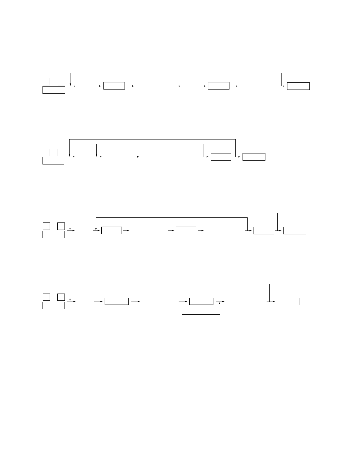
<Operation procedure>
0 3
POWER
POWER OFF/ON
Note: After initialization, the copier goes into the test mode.
START
(Exit)
(
FULL COLOR
AUTO COLOR
ENERGY SAVER Digital keys
)
(LCD ON)
Note: When icon is displayed with white letter on black background on the control panel,
it indicates the value is 1.
FC-22 ADJUSTMENT 1 - 14 January 2000 © TOSHIBA TEC
Page 23

1. 2. 2 Output check (Test mode 03)
Output signal status can be checked by inputting the following code according to this test mode 03.
Code Function Code Function Procedure
150 All output OFF 1
101
Drum motor and transfer belt motor rotation with normal running speed ON
102
Drum motor and transfer belt motor rotation with OHP copying speed (low) ON
103 Paper feed motor ON 153 Code No. 103 function OFF 1
104 Fuser motor ON 154 Code No. 104 function OFF 1
105 Color developer motor ON 155 Code No. 105 function OFF 1
106 Black developer motor ON 156 Code No. 106 function OFF 1
107 Registration clutch ON 157 Code No. 107 function OFF 1
108 Used-toner transport motor ON 158 Code No. 108 function OFF 1
109 ADU motor ON 159 Code No. 109 function OFF 1
110 Toner motor (Y) ON 160 Code No. 110 function OFF 1
111 T oner motor (M) ON 161 Code No. 111 function OFF 1
112 Toner motor (C) ON 162 Code No. 112 function OFF 1
113 Toner motor (K) ON 163 Code No. 113 function OFF 1
114 Image quality sensor shutter solenoid ON 164 Code No. 114 function OFF 1
130 Polygonal motor standby speed ON 180 Code No. 130 function OFF 1
131 Polygonal motor normal speed ON 181 Code No. 131 function OFF 1
132 Image quality sensor LED ON 182 Code No. 132 function OFF 1
133 Color registration sensor LED (front) ON 183 Code No. 133 function OFF 1
134 Color registration sensor LED (rear) ON 184 Code No. 134 function OFF 1
135
Image quality sensor mode switching ON (Black mode)
201 1st cassette feed clutch ON/OFF 3
202 2nd cassette feed clutch ON/OFF 3
203 3rd cassette feed clutch ON/OFF 3
204 4th cassette feed clutch ON/OFF 3
205 Feed path clutch ON/OFF 2
206 Bypass feed clutch ON/OFF 3
207 1st cassette tray-up motor ON (tray goes up) 2
208 2nd cassette tray-up motor ON (tray goes up) 2
209 3rd cassette tray-up motor ON (tray goes up) 2
210 4th cassette tray-up motor ON (tray goes up) 2
211 Paper-exit gate solenoid ON/OFF 3
212 Total counter count up 2
213 Ozone exhaust fan motor ON/OFF 3
214 Fuser exhaust fan motor speed Low/High 3
151 Code No. 101 function OFF 1
152 Code No. 102 function OFF 1
185
Code No. 135 function OFF (Color mode)
1
January 2000 © TOSHIBA TEC 1 - 15 FC-22 ADJUSTMENT
Page 24

Code Function Procedure
215 SIC fan motor speed Low/High 3
216 Charger wire cleaner drive motor (Y) CW/CCW (continuous reciprocating) 2
217 Charger wire cleaner drive motor (M) CW/CCW (continuous reciprocating) 2
218 Charger wire cleaner drive motor (C) CW/CCW (continuous reciprocating) 2
219 Charger wire cleaner drive motor (K) CW/CCW (continuous reciprocating) 2
220 Transfer-belt contact/release motor CW/CCW (continuous reciprocating) 2
221 Developer removal shutter open/close motor CW/CCW (continuous reciprocating) 2
223 LCF paper-feed motor ON/OFF 3
224 LCF tray motor ON/OFF 2
225 ADU feed clutch ON/OFF 3
226 ADU gate solenoid ON/OFF 3
227 ADU side motor ON/OFF 3
228 ADU end motor ON/OFF 3
235 Main charger (Y) ON/OFF 3
236 Main charger (M) ON/OFF 3
237 Main charger (C) ON/OFF 3
238 Main charger (K) ON/OFF 3
239 Developer bias (Y) DC (+) ON/OFF 3
240 Developer bias (M) DC (+) ON/OFF 3
241 Developer bias (C) DC (+) ON/OFF 3
242 Developer bias (K) DC (+) ON/OFF 3
243 Developer bias (Y) DC (–) ON/OFF 3
244 Developer bias (M) DC (–) ON/OFF 3
245 Developer bias (C) DC (–) ON/OFF 3
246 Developer bias (K) DC (–) ON/OFF 3
247 Developer bias (Y) AC ON/OFF 3
248 Developer bias (M) AC ON/OFF 3
249 Developer bias (C) AC ON/OFF 3
250 Developer bias (K) AC ON/OFF 3
251 Cleaning blade bias (Y) AC + DC ON/OFF 3
252 Cleaning blade bias (M) AC + DC ON/OFF 3
253 Cleaning blade bias (C) AC + DC ON/OFF 3
254 Cleaning blade bias (K) AC + DC ON/OFF 3
255 Transfer roller bias (Y) ON/OFF 3
256 Transfer roller bias (M) ON/OFF 3
257 Transfer roller bias (C) ON/OFF 3
258 Transfer roller bias (K) ON/OFF 3
259 Paper suction charger ON/OFF 3
260 Discharge LED (Y) ON/OFF 3
FC-22 ADJUSTMENT 1 - 16 January 2000 © TOSHIBA TEC
Page 25
Code Function Procedure
261 Discharge LED (M) ON/OFF 3
262 Discharge LED (C) ON/OFF 3
263 Discharge LED (K) ON/OFF 3
280 Laser (Y) ON/OFF 3
281 Laser (M) ON/OFF 3
282 Laser (C) ON/OFF 3
283 Laser (K) ON/OFF 3
300 Carriage fan motor rotation when standby (low speed) ON/OFF 3
301 Carriage fan motor rotation when running (high speed) ON/OFF 3
302 SCM fan motor rotation speed Low/High 3
304 Scanner exposure lamp ON/OFF 4
331 ADF pick-up roller rotation ON/OFF 3
332 ADF aligning roller rotation ON/OFF 3
333 ADF transport-belt CW rotation ON/OFF 3
334 ADF transport-belt CCW rotation ON/OFF 3
351 Scan motor (carriage 1 reciprocating) 3
352 Document motor (indicator 1 reciprocating) 3
353 ADF single-sided original feeding 3
354 ADF two-sided original feeding 3
355 ADF original exiting 3
356 ADF 2 in 1 original feeding 3
January 2000 © TOSHIBA TEC 1 - 17 FC-22 ADJUSTMENT
Page 26
<Operation procedure>
(
)
Group 1
0 3
POWER
Group 2
0 3
POWER
Group 3
0 3
POWER
(Code)
(Code)
(Code)
START START
START
START START
(One-direction operation)
(Operation ON) (Operation OFF)
(Code)(Operation ON)
(Operation OFF)
POWER OFF/ONCLEAR
(Exit)
POWER OFF/ON
(Exit)
POWER OFF/ONCLEAR
Exit
Group 4
0 3
POWER
FC-22 ADJUSTMENT 1 - 18 January 2000 © TOSHIBA TEC
(Code)
START START
(Operation ON) (Operation OFF)
CLEAR
or
6 sec. later
POWER OFF/ON
(Exit)
Page 27
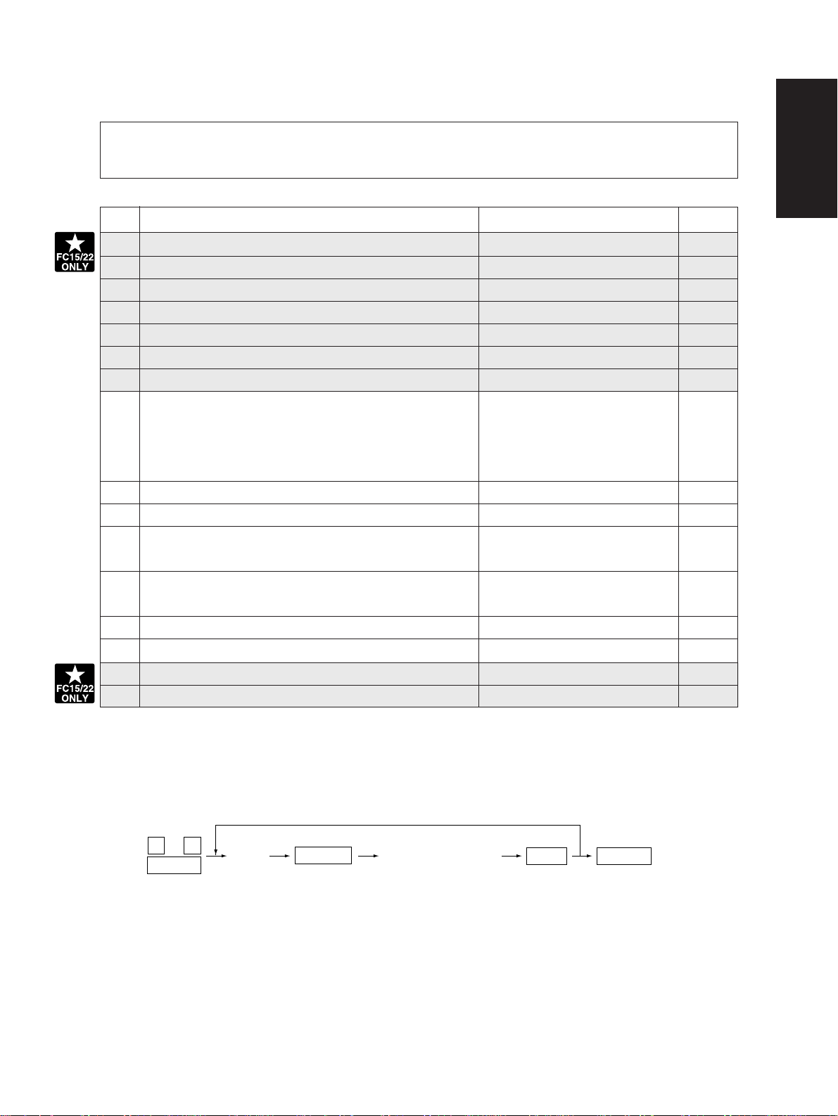
1. 2. 3 Test print mode (04)
(
)
In the 04 test print mode, you can print the test patterns matching with each item if you input the
following codes.
Code Types of test pattern Remarks
Paper size
11 2-pixel modulation pattern for creating γ table A3
12 3-pixel modulation pattern for creating γ table A3
13 1-pixel modulation pattern for checking γ table A3
14 2-pixel modulation pattern for checking γ table A3
15 3-pixel modulation pattern for checking γ table A3
24 Gray 2-pixel modulation pattern for checking γ table A3
25 Gray 3-pixel modulation pattern for checking γ table A3
204 Grid pattern (Printer reproduction ratio/Registration Pattern width: 1 dot, Pitch: 5mm A3/LD
adjustment pattern) (same as the adjustment pattern
by [05] mode [1][SETTINGS])
219 6% test pattern
220 8% test pattern None
230 Gradation check pattern (2 Pixels standard) Pattern width: 10mm, A3/LD
32 gradation steps
231 Gradation check pattern (3 Pixels standard) Pattern width: 10mm, A3/LD
32 gradation steps
234 Half tone A3/LD
256 Density check pattern A3/LD
291 2-pixel modulation pattern 1 for selecting pulse width A3
292 2-pixel modulation pattern 2 for selecting pulse width A3
Note: Full color (YMCK) mode is not available in 230, 231 and 234.
<Operation procedure>
0 4
POWER
Note: 1. When an error has occurred, it is indicated, but the recovery operation is not perfor med. So, turn the
power OFF and then back ON to clear the error.
2. During test printing, when "Wait adding toner" is displayed, the [STOP] key is disabled.
January 2000 © TOSHIBA TEC 1 - 19 FC-22 ADJUSTMENT
(Code)
START
(Test print operation)
POWER OFF/ONSTOP
Exit
Page 28
1. 2. 4 Adjustment mode (05)
In the adjustment mode 05, the following adjustment items can be corrected, changed, or checked.
*In code No. column, number after hyphen means sub-code.
Code
104 128 1~255
Scanner (secondary scanning) copy length re-
Description/Mode
production ratio adjustment.
Default
Acceptable
Value
When the value increases by 1, the
reproduction ratio in the secondary
scanning direction (vertical paper
feeding direction) increases by
approx. 0.1522%.
105 128 85~171 When the value increases by 1, the
Scanner (secondary scanning) start position
deviation
image shifts by approx. 0.1213mm
toward the trailing edge of the paper.
106 For regular 180 5~251 When the value increases by 1, the
CCD primary scanning star t
position deviation
copy mode image shifts by approx. 0.042mm
toward the front side of the paper
(machine).
108 For whole-area 133 5~251 When you input a value, which is
copy mode 47steps (equivalent to2mm)
smaller than the set value of [106],
the rear original edge and thefront
copy edge match (0.042mm/step).
135 RADF original stop position (single-sided) 8 0~15 Changes the position where the
136 RADF original stop position 8 0~15 original stops.When the value in-
(reverse side of two-sided original) creases by 1, the original stop po-
sition shifts by 1 mm awa y from the
original stopper.
137 RADF sensor automatic adjustment and – – By pressing the START key, WAIT
EPROM Initialization is displayed while the automatic
adjustment is performed.
Perform RADF EPROM Initializa-
tion when EPROM, RADF logic
PWA or sensors are replaced.
142 RADF 2-in-1 gap adjustment 8 0~15 When the value increases by 1, the
gap between two originals extend
by 1 mm.
Contents
Operation
procedure
group
1
1
1
1
1
1
6
1
FC-22 ADJUSTMENT 1 - 20 January 2000 © TOSHIBA TEC
Page 29

Code
200 All (Y, M, C, K) –
Automatic filling of dev eloper
201 Y – 0~255
material and automatic ad-
202 M – 0~255
justment of the auto-toner cir-
203 C – 0~255
cuit
204 K – 0~255
221 Color (Y, M, C) – 0~255
213 Auto toner output value 0 0~1023 Auto toner output v alue is displayed.
223 Y 130 0~255
Developer bias DC (–)
224 M 130 0~255
output adjustment
225 C 130 0~255
226 K
241 Y 120 0~255
Main
charger grid bias
242 M 120 0~255
output adjustment
243 C 120 0~255
244
Automatic adjustment of the
245
auto-toner circuit
(Without automatic filling of
developer material)
246
247
248
249
250
252-0
Main charger bias
252-1
output voltage 1 (lower)
252-2
252-3
253-0
Main charger bias
253-1
output voltage 2 (upper)
253-2
253-3
257-0
Developer bias DC (–)
257-1
output voltage 1 (lower)
257-2
257-3
258-0
Developer bias DC (–)
258-1
output voltage 2 (upper)
258-2
258-3
Description/Mode
K 116 0~255
All
(C, M, Y, K)
Y
M
C
K
Color
(Y, M, C)
Y 250 0~999
M 250 0~999
C 250 0~999
K 250 0~999
Y 900 0~999
M 900 0~999
C 900 0~999
K 900 0~999
Y 100 0~999
M 100 0~999
C 100 0~999
K 100 0~999
Y 700 0~999
M 700 0~999
C 700 0~999
K 700 0~999
Acceptable
Default
125 0~255
Value
0~255
–
0~255
–
0~255
–
0~255
–
0~255
0~255
–
0~255
–
After filling the developer from the developer cartridge (approx. 2.5min.),
auto-toner sensor output is adjusted
(approx. 2min.) to set in the range of
4.00-4.33V. (As the value increases,
the sensor output increases.)
As the value increases, the transformer
output increases. The adjustment v alue
becomes effective only when the setting
mode (08-400, 401, 409) is 0 (disabled).
As the value increases, the transformer
output increases. The adjustment v alue
becomes effective only when the setting
mode (08-400, 401, 409) is 0 (disabled).
Auto-toner sensor output is
adjusted (approx. 2 min.) to set
in the range of 4.00~4.33V. (As
the value increases, the sensor
output increases.)
Actual output voltage of main
charger grid bias. After replacing
the main high-voltage transformer,
input the value according to the
supplementary data sheet.
Actual output voltage of developer
bias. After replacing the main highvoltage transformer , input the value
according to the supplementary
data sheet.
Contents
Operation
procedure
group
5
5
5
5
5
5
10
1
1
1
1
1
1
1
1
5
4
4
4
4
4
4
4
4
4
4
4
4
4
4
4
4
January 2000 © TOSHIBA TEC 1 - 21 FC-22 ADJUSTMENT
Page 30
Code
318 Full color Y 67 0~255
Transfer bias
319 M 67 0~255
output adjustment
320 C 72 0~255
321 K 67 0~255
326 Y 67 0~255
327 M 67 0~255
328 C 72 0~255
Description/Mode
Normal paper
mode (T op face)/
thick paper 1
mode
Normal paper
mode (Reverse face)
Default
Acceptable
Value
329 K 67 0~255
330 OHP mode Y 61 0~255
331 M 101 0~255
332 C 111 0~255
333 K 141 0~255
334 Y 67 0~255
335 M 67 0~255
Thick paper
2 mode
336 C 72 0~255
337 K 67 0~255
361 Black K 56 0~255
363 K 56 0~255
Normal paper mode
(T op face)/Thic k paper 1 mode
Normal paper mode
(Reverse face)
364 OHP mode K 82 0~255
365
Transfer bias output
367-0
voltage 1 (lower)
367-1
367-2
367-3
368-0
Transfer bias output
368-1
voltage 2 (upper)
368-2
368-3
381 Full color Y 72 0~255
Transfer bias output adjustment
382 M 72 0~255
Thick paper2 mode
K 56 0~255
Y 589 0~5000
M 589 0~5000
C 589 0~5000
K 589 0~5000
Y 3929 0~5000
M 3929 0~5000
C 3929 0~5000
K 4715 0~5000
Thick paper
3 mode
383 C 72 0~255
384 K 72 0~255
385 Black
Thick paper3 mode
K 72 0~255
Contents
The bias value of the transfer roller
is set. The higher the value, the
larger the transformer output becomes. The adjustment value becomes effective only when the setting mode (08-400, 401, 409) is 0
(disabled).
Actual output voltage of transfer
roller bias. After replacing the transfer transformer, input the value according to the supplementary data
sheet.
The bias value of the transfer roller
is set. The higher the value, the
larger the transformer output becomes. The adjustment value becomes effective only when the setting mode (08-400, 401, 409) is 0
(disabled).
Operation
procedure
group
1
1
1
1
1
1
1
1
1
1
1
1
1
1
1
1
1
1
1
1
4
4
4
4
4
4
4
4
1
1
1
1
1
FC-22 ADJUSTMENT 1 - 22 January 2000 © TOSHIBA TEC
Page 31

Code
Automatic removing of dev el-
390 All (Y, M, C, K) – –
oper material
391 Color (Y, M, C) – –
Description/Mode
Default
Acceptable
392 K – –
Reproduction ratio adjustment of primary scan-
400 1222
ning direction (Fine adjustment of polygonal
motor rotation speed)
1209~1235
Value
The developer material in the developer unit is removed into the
toner bag.
When the value increases by 1, the
reproduction ratio in the primary
scanning direction (horizontal pa-
Contents
per feeding direction) decreases by
approx. 0.082%. (If the v alues of this
code 400 is changed, the values of
code 05-401, 402, 403, 404 and
474 are optimized.)
Reproduction ratio adjustment of secondary
401 1355
scanning direction (Fine adjustment of transfer
belt motor rotation speed)
1327~1382
When the value increases by 1, the
reproduction ratio in the secondary
scanning direction (vertical paper
feeding direction) decreases by
approx. 0.074%. (If the v alues of this
code 401 is changed, the values of
code 05-401, 402, 403, 404 and
474 are optimized.)
402 Fine adjustment of fuser motor rotation speed 3794 0~65535 When the value increases by 1, the
rotation speed of fuser motor decreases by 0.026%.
403 Fine adjustment of drum motor rotation speed 1700 0~65535 When the value increases by 1, the
rotation speed of the drum motors
(Y,M,C,K) decreases by 0.059%.
404 Fine adjustment of feed motor rotation speed 4289 0~65535 When the value increases by 1, the
rotation speed of the paper feed
motor decreases by 0.023%.
406 Feed motor speed adjustment – – The paper transport speed of reg-
istration roller in relation to the image printing speed is set at the optimum value. (If the value of this
code 406 is performed, the value
of code 05-404 is optimized.)
407 Color registration control forced performing – – Performs the color registration con-
trol.
Correction of fuser motor rotation speed in the
408 0 0~20 In this thick paper 3 mode, when
thick paper 3 mode
the value is increased by 1, the
fuser motor rotation speed is decreased by 0.026%.
Operation
procedure
group
6
6
6
1
1
1
1
1
6
6
1
January 2000 © TOSHIBA TEC 1 - 23 FC-22 ADJUSTMENT
Page 32

Code
Description/Mode
Default
Acceptable
V alue
Contents
427 Right margin 160 0~255 Printed page right edge void (mar-
gin) adjustment. When the value increases by 1, the void in the right
side of paper feed direction (rear
side) decreases by approx.
0.042mm.
428 Bottom margin 160 0~255 Printed page trailing edge void
(margin) adjustment. When the
value increases by 1mm, the void
in the trailing edge of paper feed
direction decreases by approx.
0.042mm.
Paper alignment
439 1st 25 0~40
(paper buckle) at
440 cassette 25 0~40
the main registra-
441 2nd 25 0~40
tion roller
442 cassette 25 0~40
443 3rd Long size 25 0~40
444 cassette Short size 25 0~40
445 4th Long size 25 0~40
446 cassette Short size 25 0~40
447 ADU Long size 25 0~40
Long size
Short size
Long size
Short size
When the value increases by 1,
the aligning (paper buckle)
increases by approx. 0.8mm.
*Long size:
Paper length 330 mm and longer
(A3/LD/A3 wide)
Short size:
Paper length 220 mm to 329 mm
448 Short size 25 0~40
449 LCF 18 0~40
450 Bypass feed 35 0~40
451 Thick paper 2 mode 35 0~50
452 Thick paper 3 mode 35 0~50
461 Color registration status display 0 0~255 The value of Y (0) shows the status
of color registration sensor error. 0
or 16 or above: Normal
1-14:
Data abnormal (sensor normal)
15: Color registration pattern reading error
Primary-scanning data write start position
470 K 100 0~255 When the value increases by 1, the
adjustment
image shifts by approx. 0.042mm
toward the right side of paper feed
direction.
Secondary-scanning data write start position ad-
474 8 1~15 When the value increases by 1, the
justment (Printer and Test print mode)
image shifts by approx. 0.6mm toward the leading edge of paper feed
direction.
Operation
procedure
group
1
1
1
1
1
1
1
1
1
1
1
1
1
1
1
1
10
1
1
FC-22 ADJUSTMENT 1 - 24 January 2000 © TOSHIBA TEC
Page 33

Operation
procedure
group
Code
Description/Mode
Default
Acceptable
Value
Contents
482 Primary-scanning reproduction ratio (scanner) 127 112~142 When the v alue increases by 1, the
reproduction ratio of the primary
scanning direction (paper feeding
in horizontal direction) decreases
by 0.082%.
484 1st cassette Y 6 0~15
Secondary-scanning data
485 2nd cassette Y 6 0~15
write start position adjust-
486 3rd cassette Y 6 0~15
ment (Copier)
487 4th cassette Y 7 0~15
When the value increases by 1, the
image shifts by approx. 0.6 mm toward the trailing edge of paper feed
direction.
488 Bypass feed Y 6 0~15
489 LCF Y 7 0~15
490 ADU Y 7 0~15
492 40 0~50 1
Paper aligning amount adjustable for the main registration roller in OHP mode when feeding from the b ypass .
Paper restarting amount adjustable f or the bypass feed
493 9 0~14 1
roller in OHP mode when restarting its roller.
When the value increases by 1, the
aligning increases by appro x. 0.8 mm.
Default 9: 68 msec.
When the value increases by 1, the
aligning increases by appro x. 7 msec.
500 Modulation mode switching, type A 0 0~255 1
501 Modulation mode switching, type B 0 0~255 1
502 Modulation mode switching, type C 0 0~255 1
503 Modulation mode switching, type D 0 0~255 1
504 Highlight processing ON/OFF 0 0~255 1
505 Screen angle change (Y) 0 0~255 1
506 Screen angle change (M) 0 0~255 1
507 Screen angle change (C) 0 0~255 1
508 Screen angle change (K) 0 0~255 1
509 Modulation data results indication 0
511
Density adjustment; density curve input, full color
8bit*4*4*5
0 0~255 4
512 Density adjustment; density curve selection, 0 0~255 1
full color
513 Density adjustment; density curve selection, 0 0~255 1
full color
514 Density adjustment; density curve selection, 0 0~255 1
full color
515 Density adjustment; density curve selection, 0 0~255 1
full color
516 Density adjustment; density curve selection, 0 0~255 1
full color
517 Density adjustment; density curve input, 0 0~255 1
monochrome
1
1
1
1
1
1
1
1
10
January 2000 © TOSHIBA TEC 1 - 25 FC-22 ADJUSTMENT
Page 34

Operation
procedure
group
Code
Description/Mode
Default
Acceptable
Value
Contents
518 Density adjustment; density curve selection, 0 0~255 1
monochrome
519 Density adjustment; density curve selection, 0 0~255 1
monochrome
520 Density adjustment; density curve selection, 0 0~255 1
monochrome
521 Density adjustment; density curve selection, 0 0~255 1
monochrome
522 Density adjustment; density curve selection, 0 0~255 1
monochrome
523 Color mode black text γ curve set selection 0 0~255 1
524 Color mode black text γ curve set selection 0 0~255 1
525 Color mode black text γ curve set selection 0 0~255 1
526 Monochrome mode black text
γ
curve set 0 0~255 1
selection
527 Monochrome mode black text
γ
curve set 0~255 1
selection
γ
528 Monochrome mode black text
curve set 0~255 1
selection
529 Monitor patch output ON/OFF switching 0~255 1
530 Filter coefficient set selection table – (0~99)*62 4
531 Scanner characteristic R for filter selection 0~8 1
532 Scanner characteristic G for filter selection 0~8 1
533 Scanner characteristic B for filter selection 0~8 1
534 Scanner correction color conversion matrix 0~15
selection
535 Basic color conversion matrix selection, type A 0~255 1
536 Basic color conversion matrix selection, type B 0~255 1
537 Basic color conversion matrix selection, type C 0~255 1
538 Basic color conversion matrix selection, type D 0~255 1
539 Operation of pre-scan unit only – 1
540 Operation equivalent to normal copying – 1
544 Automatic adjustment of scanner correction – –
color conversion matrix
545 Selection of scanner correction color 0 0:3 x 4 1:3 x 3 0
conversion matrix type
546 Indication of scanner correction color – –
conversion patch read data
547 Indication of scanner correction color –
32bit*3*10*9
conversion matrix calculation results
–
FC-22 ADJUSTMENT 1 - 25- 1 January 2000 © TOSHIBA TEC
Page 35

Operation
procedure
group
Code
550 Full color Text/Photo 128 0~255 1
"Manual density"
551 Text 128 0~255 1
fine adjustment
552 Printed image 128 0~255 1
(Center setting)
Description/Mode
Default
Acceptable
Value
When the value increases, images
made at center density become
darker.
Contents
553 Photo 128 0~255 1
554 Map 128 0~255 1
555 Black Text/Photo 128 0~255 1
556 Text 128 0~255 1
557 Printed image 128 0~255 1
558 Photo 128 0~255 1
559 Map 128 0~255 1
"Manual density"
560 Full color Text/Photo 20 0~255 1
fine adjustment
561 Text 20 0~255 1
(Darker setting)
562 Printed image 20 0~255 1
When the value increases, images
made at the “dark” side become
darker.
563 Photo 20 0~255 1
564 Map 20 0~255 1
565 Black Text/Photo 20 0~255 1
566 Text 20 0~255 1
567 Printed image 20 0~255 1
568 Photo 20 0~255 1
569 Map
20 0~255 1
January 2000 © TOSHIBA TEC 1 - 25 - 2 FC-22 ADJUSTMENT
Page 36

Operation
procedure
group
Code
"Manual density"
570 Full color Text/Photo 20 0~255
fine adjustment
571 Text 20 0~255
(Lighter setting)
572 Printed image 20 0~255
Description/Mode
Default
Acceptable
Value
Contents
When the value increases, images
made at the “light” side become
lighter.
573 Photo 20 0~255
574 Map 20 0~255
575 Black Text/Photo 20 0~255
576 Text 20 0~255
577 Printed image 20 0~255
578 Photo 20 0~255
579 Map 20 0~255
"Automatic den-
580 Full color Text/Photo 128 0~255
sity" fine adjust-
581 Text 128 0~255
ment
582 Printed image 128 0~255
When the value increases, images
become darker.
583 Photo 128 0~255
584 Map 128 0~255
585 Black Text/Photo 128 0~255
586 Text 128 0~255
587 Printed image 128 0~255
588 Photo 128 0~255
589 Map 128 0~255
604 Indication of calculation results for color – 32bit*3*4 10
conversion matrix (within design) type A
605 Indication of calculation results for color –
32bit*3*10*9
conversion matrix (within design) type B
606 Indication of calculation results for color –
32bit*3*10*9
conversion matrix (within design) type C
607 Indication of calculation results for color –
32bit*3*10*9
conversion matrix (within design) type D
611 Indication of scanner automatic color –
32bit*3*10*9
correction results
612 For paper size : Maximum value adjustment for 255 0~255 1
plain paper
613 For paper size : Maximum value adjustment for 249 0~255 1
thick paper 1
614 For paper size : Maximum value adjustment for 249 0~255 1
thick paper 2
615 For paper size : Maximum value adjustment for 240 0~255 1
thick paper 3
1
1
1
1
1
1
1
1
1
1
1
1
1
1
1
1
1
1
1
1
10
10
10
10
FC-22 ADJUSTMENT 1 - 26 January 2000 © TOSHIBA TEC
Page 37

Operation
procedure
group
Code
Description/Mode
Default
Acceptable
Value
Contents
616 For paper size : Maximum value adjustment for 255 0~255 1
OHP
617 For ID : Full color non-text area (Y) 255 0~255 1
618 For ID : Full color non-text area (M) 255 0~255 1
619 For ID : Full color non-text area (C) 255 0~255 1
620 For ID : Full color non-text area (K) 255 0~255 1
621 Calculation results indication for
γ
correction – 8bit*256*4 4
table for 2 pixels (For user automatic gradation (CMYK)
correction)
622 Calculation results indication for
γ
correction – 8bit*256*4 4
table for 3 pixels (For user automatic gradation (CMYK)
correction)
634 Calculation results indication : Pulse width – 8bit*16*4 4
selection for 1 pixel (CMYK)
635 Calculation results indication : Pulse width – 8bit*16*4 4
selection for 2 pixels (CMYK)
636 Calculation results indication : Pulse width – 8bit*16*4 4
selection for 3 pixels (CMYK)
643 Automatic adjustment of gamma correction – –
Auto-correction of gradation r 13
eproduction for each color Y, M, C, K
646 Calculation results indication : γ correction table – (8bit*65*4 10
creation for 1 pixel (CMYK))
647 Calculation results indication :
γ
correction table – (8bit*65*4 10
creation for 2 pixels (CMYK))
γ
648 Calculation results indication :
correction table – (8bit*65*4 10
creation for 3 pixels (CMYK))
649 Calculation results indication :
γ
correction table –
8bit*256*4
creation for 1 pixel
650 Calculation results indication :
γ
correction table –
8bit*256*4
creation for 2 pixels
651 Calculation results indication :
correction table –
8bit*256*4
γ
creation for 3 pixels
652 Achromatic axis equalization selection 0 0~1 1
653 Achromatic axis equalization selection 0 0~1 1
654 Achromatic axis equalization selection 0 0~1 1
655 Achromatic axis equalization selection 0 0~1 1
656 Achromatic axis equalization selection 0 0~1 1
657 Total hue adjustment 128 0~255 1
4
4
4
January 2000 © TOSHIBA TEC 1 - 26 - 1 FC-22 ADJUSTMENT
Page 38

Operation
Operation
procedure
procedure
group
group
Code
Code
Description/Mode
Description/Mode
Default
Default
Acceptable
Acceptable
Value
Value
Contents
Contents
658 Total hue adjustment 128 0~255 1
659 Total hue adjustment 128 0~255 1
660 Total hue adjustment 128 0~255 1
661 Total hue adjustment 128 0~255 1
662 Total luminance adjustment 128 0~255 1
663 Total luminance adjustment 128 0~255 1
664 Total luminance adjustment 128 0~255 1
665 Total luminance adjustment 128 0~255 1
666 Total luminance adjustment 128 0~255 1
667 Total saturation adjustment 100 0~255 1
668 Total saturation adjustment 100 0~255 1
669 Total saturation adjustment 100 0~255 1
670 Total saturation adjustment 100 0~255 1
671 Total saturation adjustment 100 0~255 1
672 Differential threshold (R-G) for ACS 0 0~255 1
673 Differential threshold (G-B) for ACS 0 0~255 1
674 Differential threshold (B-R) for ACS 0 0~255 1
675 Judgement threshold for ACS 104 0 0~255 When the value increases, originals 1
tend to be judged as monochrome,
and when the value decreases, they
tend to be judged as color in
auto-color mode.
676 Indication of results for ACS – 2
677 Outputting of results for ACS 0 0~1 1
678 AI mode setting Discrimination 0 0~4 Operation mode of discrimination
setting is changed in AI mode.
0: Standard (for regular)
1: Photograph priority
2: Only judgement of original type
3: Only judgement of original type
with photograph priority
4: Discrimination is not performed
in AI mode.
679 Macro recognition : Pre-process text threshold 0 0~255 1
adjustment
681 Macro recognition : Patch area recognition 0 0~255 1
ON/OFF
FC-22 ADJUSTMENT 1 - 26 -2 January 2000 © TOSHIBA TEC
Page 39

Operation
procedure
group
Code
Description/Mode
Default
Acceptable
Value
Contents
time is set for image discrimination.
2 digits are designated, 1st digit is
for setting A4/LT original, 2nd digit
is for setting A3/LD original. (unit:
second)
683 Macro recognition : Pre-process text threshold 0 0~7 1
adjustment
684 Macro recognition : Pre-process background 0 0~7 1
threshold adjustment
685 Macro recognition : Pre-process shading 0 0~7 1
threshold adjustment
687 Background processing : Indication of results – 2
1682 AI mode setting Time-out setting 63 11~99 Maximum amount of processing
Offset amount for
698
processing back-
699 Text 128 0~255
ground (Back-
700 Printed image 128 0~255
ground density
701 Photo 128 0~255
adjustment)
702 Map 128 0~255
Full color Text/Photo 128 0~255
703 Black Text/Photo 128 0~255
704 Text 128 0~255
705 Printed image 128 0~255
706 Photo 128 0~255
707 Map 128 0~255
708 Full color Text/Photo 128 0~255
Offset amount for
709 Text 128 0~255
processing back-
710 Printed image 128 0~255
ground (Text den-
711 Photo 128 0~255
sity adjustment)
712 Map 128 0~255
713 Black Text/Photo 128 0~255
714 Text 128 0~255
715 Printed image 128 0~255
716 Photo 128 0~255
717 Map 128 0~255
When the value increases, the
background becomes denser.
When the value increases, the te xt
becomes denser.
1
1
1
1
1
1
1
1
1
1
1
1
1
1
1
718 Micro recognition : Achromatic threshold, low 0 0~8191 1
719 Micro recognition : Achromatic threshold, high 0 0~8191 1
720 Micro recognition : Adjustment (text<->photo), 0 0~255 1
color
721 Micro recognition : Adjustment (text<->photo), 0 0~255 1
monochrome
January 2000 © TOSHIBA TEC 1 - 27 FC-22 ADJUSTMENT
Page 40

Operation
procedure
group
Code
Description/Mode
Default
Acceptable
Value
Contents
722 Micro recognition : Text emphasis adjustment, 0 0~127 1
color
723 Micro recognition : Text emphasis adjustment, 0 0~127 1
monochrome
724 Micro recognition : Black lowest level threshold, 0 0~99 1
color
725 Micro recognition : Black lowest level threshold, 0 0~99 1
monochrome
726 Micro recognition : Logo text inside threshold 0 0~100 1
Macro recognition available
727 Micro recognition : Recognition expansion / 0 0~255 1
threshold adjustment
728 Micro recognition : Recognition results output, 0 0~1999 1
color
729 Micro recognition : Recognition results output, 0 0~1999 1
monochrome
730 Sharpness Full color
731 adjustment
732 AI (text area) 0 0~31 1
733 AI (photo area) 0 0~31 1
734 Text 0 0~31 1
735 Printed image 0 0~31 1
736 Photo 0 0~31 1
Text/Photo (text area)
Text/Photo (photo area)
0 0~31 1
0 0~31 1
When the value increases, the image becomes sharper. When the
value decreases, the image becomes softer. The smaller the value,
the fewer the moire becomes .
* 0 in default is equivalent to 16
(center value).
737 Map 0 0~31 1
January 2000 © TOSHIBA TEC 1 - 27 - 1 FC-22 ADJUSTMENT
Page 41

Code
738 Black
Sharpness adjust739
ment
Description/Mode
Text/Photo (text area)
Text/Photo (photo area)
740 AI (text area) 0 0~31 1
741 AI (photo area) 0 0~31 1
742 Text 0 0~31 1
743 Printed image 0 0~31 1
744 Photo 0 0~31 1
Acceptable
Default
Value
0 0~31 1
0 0~31 1
When the value increases, the image becomes sharper. When the
value decreases, the image becomes softer. The smaller the value,
the fewer the moire becomes .
* 0 in default is equivalent to 16
(center value).
Contents
Operation
procedure
group
745 Map 0 0~31 1
746 HPF coefficient 0 0~99 1
747 HPF coefficient 0 0~99 1
748 HPF coefficient 0 0~99 1
749 HPF coefficient 0 0~99 1
750 HPF coefficient 0 0~99 1
751 LPF coefficient 0 0~99 1
752 LPF coefficient 0 0~99 1
753 LPF coefficient 0 0~99 1
754 LPF coefficient 0 0~99 1
755 LPF coefficient 0 0~99 1
756 Enlargement/reduction random interpolation 0 0~63 1
ON/OFF
757 Fixed “black” ratio adjustment, type A 0 0~255 1
758 Fixed “black” ratio adjustment, type B 0 0~255 1
759 Fixed “black” ratio adjustment, type C 0 0~255 1
760 Fixed “black” ratio adjustment, type D 0 0~255 1
761 “Black” table adjustment, type A 0 0~77 1
762 “Black” table adjustment, type B 0 0~77 1
763 “Black” table adjustment, type C 0 0~77 1
764 “Black” table adjustment, type D 0 0~77 1
765 “Black” calculation reference amount 1 0: Difference between maximum 1
specification, type A and minimum;
1: Minimum
766 “Black” calculation reference amount 1 0: Difference between maximum 1
specification, type A and minimum;
1: Minimum
767 “Black” calculation reference amount 1 0: Difference between maximum 1
specification, type A and minimum;
1: Minimum
768 “Black” calculation reference amount 1 0: Difference between maximum 1
specification, type A and minimum;
1: Minimum
FC-22 ADJUSTMENT 1 - 28 January 2000 © TOSHIBA TEC
Page 42

Operation
procedure
group
Code
Description/Mode
Default
Acceptable
Value
Contents
769 “Black” substitution method specification, type A 0 0:GCR 1:UCR 1
770 “Black” substitution method specification, type B 0 0:GCR 1:UCR 1
771 “Black” substitution method specification, type C 0 0:GCR 1:UCR 1
772 “Black” substitution method specification, type D 0 0:GCR 1:UCR 1
773 Color mode, black text γ adjustment 128 0~255 1
774 Color mode, black text γ adjustment 128 0~255 1
775 Color mode, black text γ adjustment 128 0~255 1
776 Monochrome mode, black text γ adjustment 128 0~255 1
777 Monochrome mode, black text γ adjustment 128 0~255 1
778 Monochrome mode, black text γ adjustment 128 0~255 1
779-0
Color balance Y
779-1
adjustment
Text/Photo
779-2 4
780-0 4
Text
780-1 4
780-2 4
781-0 4
Printed image
781-1 4
781-2 4
782-0 4
Photo
782-1 4
782-2 4
783-0 4
Map
783-1 4
783-2 4
784-0
M
Text/Photo
784-1 4
784-2 4
785-0 4
Text
785-1 4
785-2 4
786-0 4
Printed image
786-1 4
786-2 4
787-0 4
Photo
787-1 4
787-2 4
788-0 4
Map
788-1 4
788-2
Low density
Medium density
High density
Low density
Medium density
High density
Low density
Medium density
High density
Low density
Medium density
High density
Low density
Medium density
High density
Low density
Medium density
High density
Low density
Medium density
High density
Low density
Medium density
High density
Low density
Medium density
High density
Low density
Medium density
High density
128 0~255
128 0~255
128 0~255
128 0~255
128 0~255
128 0~255
128 0~255
128 0~255
128 0~255
128 0~255
128 0~255
128 0~255
128 0~255
128 0~255
128 0~255
128 0~255
128 0~255
128 0~255
128 0~255
128 0~255
128 0~255
128 0~255
128 0~255
128 0~255
128 0~255
128 0~255
128 0~255
128 0~255
128 0~255
128 0~255
When the value increases, the color
and mode become denser.
4
4
4
4
January 2000 © TOSHIBA TEC 1 -28-1 FC-22 ADJUSTMENT
Page 43

Code
Color balance
789-0
adjustment
789-1
789-2
790-0
790-1
790-2
791-0
791-1
791-2
792-0
792-1
792-2
793-0
793-1
793-2
794-0
794-1
794-2
795-0
795-1
795-2
796-0
796-1
796-2
797-0
797-1
797-2
798-0
798-1
798-2
Description/Mode
Text/Photo
C
Text
Printed image
Photo
Map
Text/Photo
K
Text
Printed image
Photo
Map
Low density
Medium density
High density
Low density
Medium density
High density
Low density
Medium density
High density
Low density
Medium density
High density
Low density
Medium density
High density
Low density
Medium density
High density
Low density
Medium density
High density
Low density
Medium density
High density
Low density
Medium density
High density
Low density
Medium density
High density
Acceptable
Default
Value
128 0~255
128 0~255
128 0~255
128 0~255
128 0~255
128 0~255
128 0~255
128 0~255
128 0~255
128 0~255
128 0~255
128 0~255
128 0~255
128 0~255
128 0~255
128 0~255
128 0~255
128 0~255
128 0~255
128 0~255
128 0~255
128 0~255
128 0~255
128 0~255
128 0~255
128 0~255
128 0~255
128 0~255
128 0~255
128 0~255
Contents
When the value increases, the color
and mode become denser.
Operation
procedure
group
4
4
4
4
4
4
4
4
4
4
4
4
4
4
4
4
4
4
4
4
4
4
4
4
4
4
4
4
4
4
January 2000 © TOSHIBA TEC 1 - 29 FC-22 ADJUSTMENT
Page 44

Code
817
Output value indication of image quality
sensor
818 Transfer belt surface
819 Low density pattern
820 High density pattern
821 Light amount adjustment results of image qual-
ity sensor
878 Forced performing of image quality control
879 Automatic initialization of image quality control
Description/Mode
When the light source
is OFF
Acceptable
Default
——
——
Value
— 0~1023
— 0~1023
— 0~1023
— 0~1023
— 0~255
Contents
Displays the output value of image
quality sensor when the sensor light
source is OFF.
Displays the output value of image
quality sensor when there is no test
pattern on the transfer belt.
Displays the output value of image
quality sensor when a low-density
test pattern is written.
Displays the output value of image
quality sensor when a high-density
test pattern is written.
The sensor's LED light amount adjustment value, for setting the reflected light amount from the belt
surface as the reference value.
Perform the image quality control
Perform the image quality control
and restore the initial value.
Operation
procedure
group
2
2
10
10
2
6
6
FC-22 ADJUSTMENT 1 - 30 January 2000 © TOSHIBA TEC
Page 45

<Procedure>
Group 1
0 5
POWER
0 5
POWER
(Code)
Group 2
(Code)
Group 4
0 5
POWER
START
CANCEL
(For correction)
or
START
(Code)
CANCEL or
(For correction)
(Set a value)
CLEAR
(A value
displayed)
START START
CLEAR
SET INTERRUPTor
(Stored in memory)
SET INTERRUPTor
(Changing the value
not allowed)
START
(Sub-code) (Set a value)
( ENERGY SAVER START )
(Test copy)
( ENERGY SAVER START )
(Test copy)
SET INTERRUPTor
(Stored in memory)
( ENERGY SAVER START )
(Test copy)
POWER OFF/ON
(Exit)
POWER OFF/ON
(Exit)
POWER OFF/ON
(Exit)
Group 5
0 5
POWER
(Code)
January 2000 © TOSHIBA TEC 1 - 31 FC-22 ADJUSTMENT
START
(Auto adjustment)
INTERRUPT
(Stored in memory)
( ENERGY SAVER START )
(Test copy)
POWER OFF/ON
(Exit)
Page 46

Group 6
(
)
(
)
(
)
0 5
POWER
Group 10
0 5
POWER
Group 13
(Code)
(Code) (Sub-code)
START
START START
(Auto adjustment)
START
( ENERGY SAVER START )
(Test copy)
SET INTERRUPTor
(Changing the value not allowed)
( ENERGY SAVER START )
(Test copy)
POWER OFF/ON
Exit
POWER OFF/ON
Exit
0 5
POWER
Group 15
0
POWER
(Code) (Number of pixels or type)
(Image processing calculation)
5
(Set 5 adjustment
charts for bypass)
START
INTERRUPT
(Code)
START
(Auto adjustment)
STOP
(Auto adjustment)
START
STOP
START
( ENERGY SAVER START )
(Test copy)
INTERRUPT
(Jam or Error)
CLEAR
POWER OFF/ON
Exit
POWER OFF/ON
(Exit)(Stored in memory)
FC-22 ADJUSTMENT 1 - 32 January 2000 © TOSHIBA TEC
Page 47

1. 2. 5 Setting mode (08)
The following items can be set or changed in this mode 08.
Code
200 Date and time setting – 13 digits Year/month/date/day/hour/minute/second
201 Destination selection 2
202 0 0-3 0: No external copy counter/controller de-
Externally installed copy counter/
Name Default
controller device
Allowable
input value
0-3:FC15/22
0-1:FC25P
Contents
Example: 99:08:07:5:11:30:48
0: Europe (A4/A3/Folio)
1: USA/Canada (Letter/Ledger)
2: Japan (A4/B4) 3:Others
vice 1: Coin controller 2: Copy k ey card
3: Key copy counter
204 Auto clear time setting
205 Energy saver timer setting 0
3:FC22
0:FC25P and returning to the default settings.
0-10 Time-out for cleaning control panel settings
0: Disabled
1 to 10: Set number x 15 second
0-15: FC15/22
0-19:FC25P
Timer for switching from Ready mode to
Energy Saver selected code 618.
0: Disabled 1: 30sec. 2: 60sec.
3: 90sec. 4: 120sec. 5: 150sec.
6: 3min 7: 4min 8: 5min 9: 7min
10: 10min 11: 15min 12: 20min
13: 30min 14: 45min 15: 60min
16: 90min 17: 120min
18: 180min 19: 240min
206 Auto-power shut off setting 20 0-20 Timer for switching from Ready mode to
Auto-Power Shut OFF. US Energy Star
Compliance
0: 3min 1: 5min 2: 10min 3: 15min
4: 20min 5: 25min 6: 30min
7: 40min 8: 50min 9: 60min
10: 70min 11: 80min 12: 90min
13: 100min 14: 110min 15: 120min
16: 150min 17: 180min 18: 210min
19: 240min 20: Disabled
Operation
procedure
group
1
1
1
1
1
1
January 2000 © TOSHIBA TEC 1 - 33 FC-22 ADJUSTMENT
Page 48

Code
Timer for Print job start up time
209 1 1-10 Set number x 15 seconds
Name Default
Allowable
input value
Contents
Operation
procedure
group
from copy mode when auto-clear
is disabled
212 Bypass paper default type 0 0: Plain paper; 1: OHP; 1
2: A3 wide; 3: Thick paper 1;
4: Thick paper 2; 5: Thick paper 3
217 Cassette loading status 15 0~15 1: 1st and 2nd cassette
2: 1st, 2nd, 3rd cassette
3: 1st, 2nd, 3rd, 4th cassette
4: 1st cassette (Auto cassette detection is
not available)
5: 1st cassette (Auto cassette detection is
available)
15: Auto cassette detection
6, 5~14: Change value to "3" forcibly.
(1st, 2nd, 3rd, 4th cassette)
220 Message language selection 0 0-2 0: Language 1
1: Language 2
2: Language 3
222 0 0-1 0: Disabled 1:Enabled
All clearing by key copy counter
removal
1
1
1
1
224 Judgement setting during 0 0: Always full color; 1: Detection for each 1
DF-ACS original
Telephone number for “Call for
250 0 14 digits A telephone number up to 14 digits can be
service”
253 Error code history display. – –
256 LCF paper size 0 0-1 0: A4 1: LT
258 FSMS functinon 1 0-1
259 Large size setting 0 0: A3, LD, A3W, unspecified bypass ->
0-1
entered. Use the HELP key to enter hyphens (–).
0: impossible
possible
1:
Large size
1: A3, LD, A3W, B4, LG, FOLIO, COMP,
unspecified bypass -> Large size
260 STR history indication - 2
267 C9B error code history display – – –
268 Black display/white display 0 0: Black; 1: White 1
switching
1
2
1
1
1
2
FC-22 ADJUSTMENT 1 - 34 January 2000 © TOSHIBA TEC
Page 49

Code
Forced performing of image quality
269 0 0-1 0: Disabled
control before the use-level calibration
Maximum number of copies
300 0 0-2 0:999 1:99 2:9
Name Default
Allowable
input value
1: Enabled
Contents
Operation
procedure
group
allowed
302 0-3 0: Off 1: Resettable Copy counter
Resettable
Copy and Original
counter display
UC: 0
EUR: 3
2: Resettable Original counter
3: Resettable Copy and Original counters
350 Manually placed original 0 0: Not present; 1: Present 1
detection
352 Shooting correction process 0 0: Valid; 2: Invalid 1
setting
353 SALT log table setting 0 0: Normal operation; 1
1: Forced setting on log table
(for ACS/full color);
2: Forced setting on log table
(for single color/monochrome);
3: Forced setting on log table (for CCV)
354 HDEN control 0 0: Normal operation; 1
1: HDEN control operation
355 Sharpness availability setting 1 0: Unavailable; 1: Available 1
1
1
1
360 0 0-1 RADF reversing of transport belt during
Switch back
original transporting, to align originals
against the original scale.
0: Disabled 1: Enabled
361 0 0-1 When non-standard originals are used;
RADF
Non-standard size original
detection
0: Non-standard - Machine will stop and
prompt operator to select copy size .
1: Standard - Machine continues the current job without stopping
400 Image quality control 1 1 0-1 Auto-performing of image quality control
0: Disabled
1: Enabled (Performing 08-410,413)
1
1
1
January 2000 © TOSHIBA TEC 1 - 34 -1 FC-22 ADJUSTMENT
Page 50

Code
Image quality control auto-start
407 0 0-1 When operating continuous printing, image
(continuous print)
408 1 0-1 When the accumulated print volume since
Image quality control auto-start
(accumulated print volume)
409 Image quality control 3 1 0-1 Auto-performing of image quality control
Drum temperature compensation
410 1 0-1 Performing drum temperature compensa-
control
Transfer bias temperature and
413 1 0-1 Performing transfer bias correction by tem-
humidity correction control
415 0 0-16 Accumulated total of CE1, CE2, CE4
Abnormal detection counter Y
(display/0 clearing)
416 0 0-16 Accumulated total of CE1, CE2, CE4
Abnormal detection counter M
(display/0 clearing)
417 0 0-16 Accumulated total of CE1, CE2, CE4
Abnormal detection counter C
(display/0 clearing)
Name Default
Allowable
input value
Contents
quality control is started for every print volume set for continuos print (08-453).
0: Disabled
1: Enabled (Set value of 08-453)
the last image quality control, set in 08455, is attained, new image quality control
automatically starts after the current printing job.
0: Disabled
1: Enabled (Setting value of 08-455)
0: Disabled
1: Enabled (Performing 08-410,413)
tion for image quality control.
0: Disabled 1: Enabled
* When ‘Image quality controls 1 and 3 (08400,409)’ are 1(Enabled), this is reflected.
perature and humidity for image quality
control.
0: Disabled 1: Enabled
* When ‘Image quality controls 1 and 3 (08400,409)’ are 1(Enabled), this is reflected.
(Max.16)
* Enabled when ‘Image quality control 3
(08-401)’ is 1(Enabled).
(Max.16)
* Enabled when ‘Image quality control 3
(08-401)’ is 1 (Enabled).
(Max.16)
* Enabled when ‘Image quality control 3
(08-401)’ is 1 (Enabled).
Operation
procedure
group
1
1
1
1
1
1
1
1
January 2000 © TOSHIBA TEC 1 - 35 FC-22 ADJUSTMENT
Page 51

Code
418 0 0-16 Accumulated total of CE1, CE2, CE4
Abnormal detection counter K
(display/0 clearing)
Image quality control auto-start
452 4 0-24 Setting time (hour) of Image quality con-
time setting (ready)
Image quality control auto-start
453 300 0-999 Setting print volume (number of sheets) to
print volume setting (continuous
printing)
Image quality control auto-start
455 10 0-30 Setting print volume (x 100 sheets) to au-
print volume setting (accumulated print volume)
Name Default
Allowable
input value
Contents
(Max.16)
* Enabled when ‘Image quality control 3
(08-401)’ is 1 (Enabled).
trol auto-start (ready)
automatically start Image quality control
(continuous printing)
tomatically start Image quality control (accumulated print volume)
480 Paper source priority 0 0-5 0: A4/LT 1: LCF 2: 1st cassette
3: 2nd cassette 4: 3rd cassette
5: 4th cassette
481 Automatic paper source change 1 0-1 0: OFF 1:Normal
When 1 is set, a paper source becomes
empty and the same size paper is present
in another source, the machine will automatically switch to that source of paper.
Pre-running rotation of polygonal
485 0 0-1 Setting of pre-running rotation of polygo-
motor
491
Out of specified paper size printing 0 0-1 0: Disabled
nal motor
0:
Low speed rotation (Pre-running rotation)
1: Stop
1: Enabled
505 Paper (plain paper, OHP, thick 1 0: Compatible paper not present;
paper). 1: Compatible paper present
Switched according to image
processing
507 Filter setting selection in Fiery 0 0-1 0: non-filter mode (OFF)
scanning 1: filter mode (ON)
558 Start setting of developer 1 0-1 0: Disabled
material counter image quality 1: Image quality control is started on
control each setting counter (08-559).
559 Start count setting of developer 100 0-999 Image quality control start count is set
material counter image quality when (08-558) is used
control
Operation
procedure
group
1
1
1
1
1
1
1
1
1
1
1
1
FC-22 ADJUSTMENT 1 - 36 January 2000 © TOSHIBA TEC
Page 52

Code
Name Default
Allowable
input value
Contents
601 Secondary scanning 0 0: 100%; 1: 101%
reproduction ratio adjustment
603 Automatic duplexing mode 0 0-3 0: Disabled
1: Single-sided to Duplexed
2: Two-sided to Duplexed
3: User selection
604 APS (Automatic Paper Selection) 0 0-2 0: APS mode 1: AMS mode 2: None
AMS (Automatic Magnification
Selection)
Mode priority at power on
605 SAPS mode 1 0: All originals detected;
1 First original only
606 Edge erase default setting 0 0: Invalid; 1: Valid
Operation
procedure
group
1
1
1
1
1
January 2000 © TOSHIBA TEC 1 - 36 -1 FC-22 ADJUSTMENT
Page 53

Code
Name Default
Allowable
input value
Contents
607 RADF priority mode 0 0-1 0: Continuous feeding by START key
1: SADF (A utomatic feeding by setting originals)
608 Function clearing immediately 0 0: Invalid; 1: Valid
after copying
611 Book duplexing copy priority 0 0-1 0: Left page to right page
(left/right page) 1: Right page to left page
612 Image repeat gap 5 0-10mm
613 Univ ersal cassette size 0-13 0: A3 1: A4 2: A4-R 3: A5-R 4: B4
UC:12
EUR:13
5: B5 6: B5-R 7: LT 8: LT-R 9: LD
10: LG 11: ST 12: COMPUTER
13: FOLIO
614 Function clearing LED flashing 1 0: Invalid; 1: Valid
615 F ree size definition X 210 0 – 432 0: Invalid; Other than
not used 0: Valid
616 F ree size definition Y 297 0 – 307 0: Invalid; Other than
not used 0: Valid
617 RADF image shifting 0 0-1 0: Without shift 1: With shift
618 Energy saver mode 0 0-1 0: Energy saver mode with prior ity aim of
energy saving (Refer to 08-712)
1: Energy saver mode with priority aim of
returning to copying (Refer to 08-713)
Initial value setting of center void
619 10 0-50
width
620
APS forced start setting /selection
0 0-2 0: Single press of key
1: Double press of key 2: Disabled
624 Cut width for all-area copying 0 0 – 2 mm (unit: 0.1)
625 Blank paper prevention mode 0 0: Invalid; 1: Valid
628 Macro recognition function 1 0: Invalid; 1: Valid
629 Macro recognition function 1 0: Invalid; 1: Valid
during ADF
630
Automatic b ypass-tray/cassette change
631
Color release control for DF-ACS
Gradation correction disclosure
632 1 0-2 0: Service technician
level
0 0-1 0: Disabled 1: Enabled
0 0-1 0: Disabled 1: Enabled
1: Administrator 2: User
633 By-department control: Black 0 0: Invalid; 1: Valid
copies free
634 Initial value setting of image re- 2 2-8
peat frequency
635 RADF mixed size original priority 0 0-1
0: Same originai size 1: Mixed original size
Operation
procedure
group
1
1
1
1
1
1
1
1
1
1
1
1
1
1
1
1
1
1
1
1
1
1
January 2000 © TOSHIBA TEC 1 - 37 FC-22 ADJUSTMENT
Page 54

Operation
procedure
group
Code
Name Default
Allowable
input value
Contents
636 APS thick paper compatibility 0 0:Plain paper; 1: Thick paper; 1
2: Mixed
Automatic sorting mode priority
641 0 0-3 0: OFF 1: STAPLE 2: SORT 1
from the RADF
Sorter mode priority at power ON
642 0 0-3 0: NON SORT 1: STAPLE 2: SORT 1
(for AC)
3: GROUP
3: GROUP
649 Monochrome copying when 1 0: Prohibited; 1: Allowed 1
empty of color toner
653
Machine administrator’s password
0000
0000-9999 1
655 Off-level setting f or auto off-mode 0 0: Power shutoff; 1: Low power 1
γ
656 Execution mode for self 0 0 – 255 0: Normal; 1: Pulse; 2:
;1
diagnostic image processing 3: Scanner correction 8 color conversion;
16: Other
664 Switching of aging ADF operation 0 0: Single-side; 1: Both-side 1
668 All clearing of ID codes - 3
669 All clearing of image processing - 3
05 adjustment values
670 All clearing of halfway results - 3
of color conversion
671 All clearing of pulse width - 3
selection adjustment results
672 All clearing of
γ
correction - 3
table adjustment results
678 Mode memory initialization - 3
679 Weekly timer initialization - 3
681 Support for cascading exit 0~1 0: Invalid; 1: Valid 1
682 (Auto job start: Magazine-sort 0 0: Left-hand opening; 0
setting) 1: Right-hand opening
700 Fuser thermistor status counter 0 0-9 2: 2nd-time abnormality of thermistor/ 1
(C7 counter) heater at warming-up start
3: Unused 6: Thermistor abnormal after
“ready” is attained.
9: Heater abnormal after “ready” is
attained (high temp.)
712 Upper and lower fuser roller tem- 2 0-6 0: OFF 1: 60°C 2: 70°C 3: 80°C 1
perature for energy saver mode 4: 115°C 5: 125°C 6: 135°C
with priority aim of energy
saving
January 2000 © TOSHIBA TEC 1 - 37 - 1 FC-22 ADJUSTMENT
Page 55

Code
713 5 0-6 0:OFF 1:60°C 2:70°C
Upper and lower fuser roller tem-
perature for energy saver mode
with priority aim of returning to
copying
742 Color registration control 0 0-1 0: Automatic 1: Manual
743 1 0-1 0: Disabled 1: Enabled
801
Electronic total copy/print counter
Name Default
✽
Color registration control for
warming-up
802 Large paper size double count 0 0-2 0: Disabled
✽
803
Short-size counter (postcard -A4/LT)
804 Long-size counter (B4 - A3 wide) 0 0-999999 Display of counter value
Allowable
input value
3:80°C 4:115°C 5:125°C 6:135°C
0 0-999999 Electronic counter counts all copies and
prints including all test mode copies.
* The mechanical counter only counts the
customers’ copies and prints , not test mode
copies or prints.
1: Double count - A3, LD, A3 wide
2: Doub le count - A3, LD , A3 wide, B4, LG,
FOLIO, COMP
0 0-999999 Display of counter value
Contents
805 Full-color print counter (Copier) 0 0-999999 Display of counter value (Code 08-802 is
✽
reflected)
806 Black print counter (Copier) 0 0-999999 Display of counter value (Code 08-802 is
✽
Mono-color print counter (Copier)
807
0 0-999999 Display of counter value (Code 08-802 is
✽
808 Bypass counter 0 0-999999 Display of counter value (Single count for
809 LCF counter 0 0-999999 Display of counter value (Single count for
810 Full-color print counter (Printer) 0 0-999999 Display of counter value (Code 08-802 is
✽
811 Black print counter (Printer) 0 0-999999 Display of counter value (Code 08-802 is
✽
812
Mono-color print counter (Printer)
0 0-999999 Display of counter value (Code 08-802 is
✽
813 Test print counter 0 0-999999 In case of Test print, only this counter is
✽
814 Single-sided print counter 0 0-999999 Display of counter value (Single count for
reflected)
reflected)
every paper size)
every paper size)
reflected)
reflected)
reflected)
counted.Display of counter value
every paper size)
Operation
procedure
group
1
1
1
1
1
1
1
1
1
1
1
1
1
1
1
1
1
✽ Refer to "Counter function and maintenance chacke list"
FC-22 ADJUSTMENT 1 - 38 January 2000 © TOSHIBA TEC
Page 56

Code
815 Duplexed print counter 0 0-999999 Display of counter value (Single count for
817 Bypass jam counter 0 0-999999 Accumulated total of E12
818 Registration jam counter 0 0-999999 Jam on paper trailing edge by registration
820 Paper exit jam counter 0 0-999999 Accumulated total of E01, E02
822 ADU counter 0 0-999999 ADU feed counter
Name Default
Allowable
input value
Contents
every paper size)
roller
Display of counter value (Single count for
every paper size)
824 RADF original counter 0 0-999999 RADF feed counter
Display of counter value (Single count for
every paper size)
825 LCF jam counter 0 0-999999 Accumulated total of E19, E21
826 ADU paper-feed jam counter 0 0-999999 Accumulated total of E11, E54
827 ADU stack jam counter 0 0-999999 Accumulated total of E50, E51, E52
831 Key copy counter function 1 0-3 1: PPC 2: Printer 3: PPC/Printer
832 1st cassette counter 0 0-999999 Paper feed counter of 1st cassette
Display of counter value (Single count for
every paper size)
833 2nd cassette counter 0 0-999999 Paper feed counter of 2nd cassette
Display of counter value (Single count for
every paper size)
834 3rd cassette counter 0 0-999999 Paper feed counter of 3rd cassette
Display of counter value (Single count for
every paper size)
835 4th cassette counter 0 0-999999 Paper feed counter of 4th cassette
Display of counter value (Single count for
every paper size)
836 1st cassette jam counter 0 0-999999 Accumulated total of E13, E22
837 2nd cassette jam counter 0 0-999999 Accumulated total of E14, E23
838 3rd cassette jam counter 0 0-999999 Accumulated total of E15, E24
839 4th cassette jam counter 0 0-999999 Accumulated total of E16, E25
Drum Y life counter (display/0
840 0 0-65535 Number of printed sheets
✽
clearing)
✽
Drum M life counter (display/0
841 0 0-65535 Number of printed sheets
clearing)
Display of counter value (Code 08-858 is
reflected)/0 clearing
Display of counter value (Code 08-858 is
reflected)/0 clearing
Operation
procedure
group
1
1
1
1
1
1
1
1
1
1
1
1
1
1
1
1
1
1
1
1
✽ Refer to "Counter function and maintenance chacke list"
January 2000 © TOSHIBA TEC 1 - 39 FC-22 ADJUSTMENT
Page 57

Code
✽
842 0 0-65535 Number of printed sheets
Drum C life counter (display/0
clearing)
✽
✽
✽
✽
✽
✽
✽
✽
✽
✽
✽
✽
✽
Drum K life counter (display/0
843 0 0-65535 Number of printed sheets
clearing)
Developer Y counter (display/0
844 0 0-999999 Number of printed sheets
clearing)
Developer M counter (display/0
845 0 0-999999 Number of printed sheets
clearing)
Developer C counter (display/0
846 0 0-999999 Number of printed sheets
clearing)
Developer K counter (display/0
847 0 0-999999 Number of printed sheets
clearing)
851 0 0-65535 Frequency that Y, M and C wire cleaning
“Color” charger wire cleaner
counter (display/0 clearing)
“Black” charger wire cleaner (dis-
852 0 0-65535 Frequency that K wire cleaning pad recip-
play/0 clearing)
853 0 0-999999 Number of printed sheets
Transfer-belt unit counter (display/0 clearing)
854 0 0-999999 Number of printed sheets
Fuser unit counter (display/0
clearing)
855 0 0-999999 Number of printed sheets
Fuser oil-roller counter (display/
0 clearing)
856 0 0-999999 Rotation time of fuser motor (sec.)
Fuser oil-roller time counter (dis-
play/0 clearing)
857 Counter setting for PM 0 0-999999 Counter value (number or sheets)
858 OHP/thick-paper double count 1 0-1 0: Disabled:
Name Default
Allowable
input value
Contents
Display of counter value (Code 08-858 is
reflected)/0 clearing
Display of counter value (Code 08-858 is
reflected)/0 clearing
Display of counter value (Code 08-858 is
reflected)/0 clearing
Display of counter value (Code 08-858 is
reflected)/0 clearing
Display of counter value (Code 08-858 is
reflected)/0 clearing
Display of counter value (Code 08-858 is
reflected)/0 clearing
pads reciprocate
rocates
Display of counter value (Code 08-858 is
reflected)/0 clearing
Display of counter value (Code 08-858 is
reflected)/0 clearing
Display of counter value (Code 08-858 is
reflected)/0 clearing
Display of counter value/0 clearing
Double count - A3 wide, A3, LD, B4, LG, FOLIO, COMP
1: Enabled:
Quadruple count - A3 wide, A3, LD, B4, LG, FOLIO, COMP
Double count - A4, A4-R, L T, LT-R, B5, B5-R, ST -R, A5, A6-R
Operation
procedure
group
1
1
1
1
1
1
1
1
1
1
1
1
1
1
✽ Refer to "Counter function and maintenance chacke list"
FC-22 ADJUSTMENT 1 - 40 January 2000 © TOSHIBA TEC
Page 58

0
0
0
0
2
Allowable
input value
0 – 999999
0 – 999999
0 – 999999
0 – 999999
0 – 999999
0 – 999999
0 – 999999
0 – 999999
0 – 999999
0 – 999999
1 – 2
Contents
Display of counter value/0 clearing
Display of counter value/0 clearing
Display of counter value/0 clearing
Display of counter value/0 clearing
(sec.)
Display of counter value/0 clearing
(sec.)
Display of counter value/0 clearing
(sec.)
Display of counter value/0 clearing
(sec.)
Display of counter value/0 clearing
1: A3, LD, A3W
2: A3, LD, A3W, B4, LG, FOLIO, COMP
Code
Drum Y drive counter (display/0
867 0 0-999999 Rotation time of Y drum drive motor (sec.)
✽
clearing)
Drum M drive counter (display/0
868 0 0-999999 Rotation time of M drum drive motor (sec.)
✽
clearing)
Drum C drive counter (display/0
869 0 0-999999 Rotation time of C drum drive motor (sec.)
✽
clearing)
Drum K drive counter (display/0
870 0 0-999999 Rotation time of K drum drive motor (sec.)
✽
clearing)
✽
✽
✽
✽
Developer Y time counter (dis-
871 0 0-999999 Rotation time of color development motor
play/0 clearing)
Developer M time counter (dis-
872 0 0-999999 Rotation time of color development motor
play/0 clearing)
Developer C time counter (dis-
873 0 0-999999 Rotation time of color development motor
play/0 clearing)
Developer K time counter (dis-
874 0 0-999999 Rotation time of black development motor
play/0 clearing)
876
Full color, large size copy counter
877
Full color, small size copy counter
Name Default
878 Black, large size copy counter 0
879 Black, small size copy counter 0
880
Mono-color, large size copy counter
881
Mono-color, small size copy counter
882
Printer 0
883 counter 0
884 (Printer)
885
888
Long size setting of Setting code
Full-color
Long size
Short size
Black 0
Long size
Short size 0
(08-876~885)
Operation
procedure
group
1
1
1
1
1
1
1
1
1
1
1
1
1
1
1
1
1
1
1
1
Current counter value for PM
892 0 0-999999 Total n umber of sheets (Copier+printer) for
✽
(display/0 clearing)
life related (double count)
Display of counter value (Code 08-858 are
reflected.)/0 clearing
✽ Refer to "Counter function and maintenance check list"
January 2000 © TOSHIBA TEC 1 - 41 FC-22 ADJUSTMENT
1
Page 59

Code
✽
894 0
Drum drive total counter for color
PM time counter (display/0 clear-
ing)
✽
896 0 0-999999 Number of color printed sheets
Current counter value for color
PM (display/0 clearing)
✽
897 Counter setting for color PM 0 0-999999 Counter value (number of sheets)
✽
898 0
Drum drive total counter for PM
life-time counter (display/0 clear-
ing)
900
Firmware version (Basic part ROM)
902 Engine ROM version (LGC) – –
903 Engine ROM version (IMC) – –
904 SCAN ROM version – –
906
Macro recognition, control version
Name Default
Allowable
input value
0-999999999
0-999999999
––
Rotation time(sec.) of Y, M and C drum
drive motor
Display of counter value/0 clearing
Display of counter value (Code 08-858 are
reflected.)/0 clearing
Rotation time(sec.) of K drum drive motor
Display of counter value/0 clearing
Contents
-2
917 Waiting time for requesting 3 0: Invalid; 1 – 9: Set value x 5 seconds 1
scanner resource acquisition
918 Auto clearing if no copy paper is 0 0: Does not start; 1: Starts 1
available dur ing MFP 0: Invalid; 1: Valid
When no
copy paper is
available,
printing:
919 Automatic printer restart during 1 0: Invalid; 1: Valid 1
auto job start
956 Setting FC key when default 0 0: Invalid; 1: Valid 1
cassette is empty of paper
957 Position aligning icon displaying 0 0: Invalid; 1: Valid 1
958 Time setting icon displaying 0 0: Invalid; 1: Valid 1
961 Scanning order in dual-page 0 0: From right; 1: From left 1
copying
Operation
procedure
group
1
1
1
1
2
2
2
2
997 Long/Short size counter List display of Money collection counter
––
2
(08-876~885)
✽ Refer to "Counter function and maintenance check list"
January 2000 © TOSHIBA TEC 1 - 41 - 1 FC-22 ADJUSTMENT
Page 60

<Operation procedure>
(
)
(
)
(
)
Group 1
0 8
POWER
Group 2
Group 3
0 8
POWER
0 8
POWER
(Code) (Set a value)
(Code)
START
CANCEL or
For correction
(Code) (System mode display)
CLEAR
START
(Changing the value is not allowed)
START
SET INTERRUPTor
SET INTERRUPTor
(Stored in memory)
POWER OFF/ON
(Exit)
POWER OFF/ON
Exit
POWER OFF/ON
Exit
FC-22 ADJUSTMENT 1 - 42 January 2000 © TOSHIBA TEC
Page 61

1. 2. 6 Registering/changing ID codes
When ID codes are registered, copy count will be classified according to each ID code. Copies cannot
be made without entering one of the ID codes registered with digital keys.
Procedure for using the ID code mode:
0 8
POWER
600 2
START
Procedure for registering ID codes:
8
START
POWER
ENERGY SAVER (registered)
display
(Input a next code)
START
(ID registration mode completed)
Warming up
display Enter a 4-digit ID code.
ENERGY SAVER (registered)
(Dept. control)
(Example: 0525)
[0525 ]
[ 0 0 0 0]
Full color Black Mono-color Total
Normal copy mode
SET
(Up to 120 ID codes can be registered)
POWER OFF
ID
January 2000 © TOSHIBA TEC 1 - 43 FC-22 ADJUSTMENT
Page 62

Correcting ID code
8
START
POWER
Erasing an ID code:
[0525 ]
[ 0 0 0 0]
CLEAR
Displaying the next ID code:
ID (Next ID code displayed)
Adding an ID code
While
displayed
Changing the “full-color” counter:
Changing the “black” counter:
display
ENERGY SAVER (registered)
ENERGY SAVER (registered)(Input an ID code)
ENERGY SAVERHELP (registered)(Input a counter value.)
Press
ENERGY SAVERHELP (registered)(Input a counter value)twice
Changing the “mono-color” counter:
Press
ENERGY SAVERHELP (registered)(Input a counter value)3 times
To finish the registration mode and return to normal copy mode:
Warming up Normal copy modeSTART
FC-22 ADJUSTMENT 1 - 44 January 2000 © TOSHIBA TEC
Page 63

1.3 Adjustment Order (Copy Image Related Adjustment)
The diagram below explains the main procedures for image related adjustment.
When replacing components which have other specified instructions for adjustment, those specified
instructions are to be obeyed in priority.
In the following diagram, the solid lines with arro w lead to essential ajustments, while the dotted lines
lead to adjustments to be performed if necessary.
Developer material Processing unit (EPU) Transfer/transport unit
Adjustment item Code in mode 05
1.4 Automatic adjustment of the auto- 200-204, 221
toner circuit
▼
▲
▼
1.5 Automatic initialization of image 879
quality control
Adjustment item Code in mode 05
Copy image dimensional adjustment
Adjustment
order
1 1.6.1 Paper alignment (paper buckle) at the main registration roller 439 - 452
2 1.6.2 Feed motor speed adjustment 406
1.6.3
3 (a) Reproduction ratio adjustment of primary scanning direction 400
Printer
4 (b) Primary-scanning data write start position adjustment 470
related
5 (c) Reproduction ratio adjustment of secondary scanning direction 401
adjustment
6 (d) Secondary-scanning data write start position adjustment 474
7 (Fine adjustment of feed motor rotation speed)* 404
8 (a) Image distortion adjustment –
1.6.4
9 (b) Image skewing adjustment –
Scanner
10 (c) Primary-scanning reproduction ratio (scanner) 482
related
11 (d) Scanner copy length reproduction ratio adjustment 104
adjustment
12 (e) CCD primary scanning start position deviation 106, 108
13 (f)
14 (g) Scanner (secondary scanning) start position deviation 105
15 (h) Right margin (Printed page right edge void adjustment) 427
16 (i) Bottom margin (Printed page trailing edge void adjustment) 428
Secondary-scanning data write start position adjustment (Copier) 484 - 490
▲
▼
1.7
Automatic adjustment of gamma correction
Adjustment item Code in mode 05
643
Parts to be replaced
Drum Transfer belt
Main charger wire
Main charger grid
▼
Items
* “Fine adjustment of feed motor rotation speed”
should be adjusted after printer related adjustment.
Code in
mode 05
▼
Image quality adjustment
▼
END
Items
1.8 Density adjustment 550 - 589
1.9 Color balance adjustment 779 - 789
1.10 Offset amount for processing background 698 - 717
1.11 Judgement threshold for ACS 675
1.12 AI mode setting 678, 682
1.13 Sharpness adjustment 730 - 745
▲
Code in mode 05
January 2000 © TOSHIBA TEC 1 - 45 FC-22 ADJUSTMENT
Page 64

1. 4 Automatic Adjustment of the Auto-Toner Circuit
With this copier, the filling and removing of developer material is automatically performed by operation from the control panel. In addition, the auto-toner sensor is automatically adjusted successively
after the automatic filling of developer material.
<Operation procedure>
Note: At the time of unpacking, if developer material is not filled, the steps (3) and (4) below do not need
to be performed.
(1) Remove the toner cartridges.
(2) While pressing [0] and [5] simultaneously , turn the pow er ON. The f ollowing appears on the displa y:
100% A A3
[0] [5]
[POWER]
촞 TEST MODE
(3) Input a code with digital keys and press the [START] key.촞The developer material is removed.
Code 390 : All developer materials are removed (developer materials Y, M, C and K).
391 : All color developer materials are removed (developer materials Y, M and C).
392 : Only developer material K is removed.
(4) After all developer materials are removed, press the [INTERRUPT] key.
Time required for removing All developer materials : Approx.10 min.
Color developer materials only : Approx. 6 min.
Developer material K only : Approx. 3 min.
(5) Open the front cover, install the developer cartridge(s) and then close the cover.
* When installing or uninstalling the developer cartridge(s), it is necessary to open and close the
front cover.
(6) Input a code with digital keys and press the [START] key.
Code 200 : All developer materials 221 : Color developer materials only
204 : Developer material K only
100% 200 A3
(Code) 촞 [START] 촞 TEST MODE
FC-22 ADJUSTMENT 1 - 46 January 2000 © TOSHIBA TEC
Page 65

(7) When the copier starts operating, a message “WAIT” is shown and the developer material filling
starts (approx. 2 minutes and 30 seconds).
WAIT
(8) Approx. 2 minutes after the developer material filling is finished, the following display appears:
훾촞 Y:6.30V M:6.38V C:6.38V K:6.38V
훿촞 61%
훽촞 Y:4.00V M:4.00V C:4.00V K:4.00V
Upper line 훾 : Current sensor voltages (V)
Middle line 훿 : Humidity (%)
Lower line 훽 : Target values (V) for adjustment reference v oltages
Note:
• The current sensor voltages (V) shown in 훾 automatically changes, gradually approaching the target values
for adjustment reference voltages shown in 훽.
• Values are displayed only for the developer materials being filled.
(9) In 30 to 60 seconds, the current sensor voltages (V) in 훾 are con verged to those in 훽. The humidity
shown in 훿 disappears, and the sensor output control values (bit values) are shown instead.
훾촞 Y:4.00V M:4.00V C:4.00V K:4.00V
훿촞 Y: 135 M: 135 C: 135 K: 135
훽촞 Y:4.00V M:4.00V C:4.00V K:4.00V
Note: Be careful that the values in 훽, 훾 and 훿 vary with humidity.
훽 : Target value (V) for adjustment reference voltage
Humidity (%) Y M C K
~59.9 4.00 4.00 4.00 4.00
60.0~74.9 4.14 4.14 4.14 4.12
75.0~ 4.35 4.35 4.35 4.31
January 2000 © TOSHIBA TEC 1 - 47 FC-22 ADJUSTMENT
Page 66

훾 : Current sensor voltage (V)
Humidity (%) Y M C K
~59.9 3.95~4.05 3.95~4.05 3.95~4.05 3.95~4.05
60.0~74.9 4.09~4.19 4.09~4.19 4.09~4.19 4.07~4.17
75.0~ 4.30~4.40 4.30~4.40 4.30~4.40 4.26~4.36
(10) If an adjustment error occurs, values of the color in problem displa yed in A, B or C are replaced with
“
”.
***
As for properly adjusted colors, press the [INTERRUPT] key to store their adjustment results in
memory.
(11) Press the [INTERRUPT] key to store the adjustment results in memor y. The screen returns to the
initial display.
100% A A3
[INTERRUPT] 촞 TEST MODE
(12) Remove the developer cartridge(s).
(13) Install the toner cartridge(s).
FC-22 ADJUSTMENT 1 - 48 January 2000 © TOSHIBA TEC
Page 67

<Troubleshooting in auto-toner sensor adjustment> (measures against adjustment error)
Check which color is in adjustment error.
훹
Is the developer unit filled with developer material? (Is the developer cartridge empty?)
NO
촞 (1) Check if the shutter seal is removed from the developer cartridge.
(2) Check the toner motor performance, using the following test mode.
Y : 03-110 ON, 03-160 OFF
M: 03-111 ON, 03-161 OFF
C: 03-112 ON, 03-162 OFF
YES K: 03-113 ON, 03-163 OFF
(3) Check if the developer cartridge gears rotate properly.
훹
As for the colors completely adjusted, press [INTERRUPT] to store their adjustment results in memory.
Perform again the adjustment procedure to the color in adjustment error.
05-200: All developers 05-201: Developer Y
05-202: Developer M 05-203: Developer C
05-204: Developer K 05-221: Color developers
훹
Is the adjustment completed?
NO
촞 (1) Check if the developer unit is filled with developer material.
(2)
Check if any toner or carrier is stuck on the transf er belt or the drum surf ace at the base of EPU .
NO
촞 • Check the high-voltage contacts.
YES Replace disabled parts.
YES Replace EPU.
훹
Perform the adjustment procedure again.
훹
• Main charger wire
• Main charger grid
• Developer bias
훹
Press [INTERRUPT] to store the adjustment results in memory.
January 2000 © TOSHIBA TEC 1 - 49 FC-22 ADJUSTMENT
Page 68

1.5 Automatic Initialization of Image Quality Control
(1) At the time of unpacking
Prior to copy-image dimensional adjustment, perform the 05-879 “Automatic initialization of image
quality control” procedure.
(2) When any of the following parts is replaced, be sure to perform the 05-879 “Automatic initialization
of image quality control” procedure.
• Processing unit • Transfer belt unit • Photoconductive drum
• Laser optical unit •Image quality sensor • Developer material
Note: When performing automatic adjustment of gamma correction in addition, “Automatic initialization of
image quality control” should be done first.
(3) When performing automatic adjustment of gamma correction in cases other than the above ones,
do the 05-878 “Forced performing of image quality control” procedure before automatic gamma
value correction.
Code Adjustment item Content
878 Forced performing of <Procedure>
image quality control (1) While pressing [0] and [5] simultaneously, turn the power ON. 촞
Adjustment mode
(2) Input [878] with digital keys and press [START].
(3) When the adjustment finishes normally, the copier will return to
the adjustment mode’s initial state.
If an abnormal condition has occurred, take appropriate action by
referring to “4. TROUBLESHOOTING”.
879 Automatic initialization of <Procedure>
image quality control (1) While pressing [0] and [5] simultaneously, turn the power ON. 촞
Adjustment mode
(2) Input [879] with digital keys and press [START].
(3) When the adjustment finishes normally, the copier will return to
the adjustment mode’s initial state.
If an abnormal condition has occurred, take appropriate action by
referring to “4. TROUBLESHOOTING”.
FC-22 ADJUSTMENT 1 - 50 January 2000 © TOSHIBA TEC
Page 69

1. 6 Copy Image Dimensional Adjustment
There are sever al adjustment items in the copy image dimensional adjustment, as listed belo w. Prior
to this image dimensional adjustment, perform the automatic initialization of image quality control
(code [879] in adjustment mode 05). When adjusting these items, the following adjustment order
should strictly be observed.
Adjustment items Code in mode 05
Paper alignment (paper buckle) at the main registration roller 439 – 452
Feed motor speed adjustment 406
(a) Reproduction ratio adjustment of primary scanning direction 400
(Fine-adjustment of polygonal motor rotation speed)
(b) Primary-scanning data write start position adjustment 470
(c) Reproduction ratio adjustment of secondary scanning direction 401
adjustment
Printer related
( Fine adjustment of feed motor rotation speed)* 404
Scanner related adjustment
(Fine-adjustment of transfer belt motor rotation speed)
(d) Secondary-scanning data write start position adjustment 474
(a) Image distortion adjustment –
(b) Image skewing adjustment –
(c) Primary-scanning reproduction ratio (scanner) 482
(d) Scanner copy length reproduction ratio adjustment 104
(e) CCD primary-scanning start position deviation 106, 108
(f) Secondary scanning data write start position adjustment (Copier) 484 – 490
(g) Scanner (secondary scanning) start position deviation 105
(h) Right margin (Printed page right edge void adjustment) 427
(i) Bottom margin (Printed page trailing edge void adjustment 428
* “Fine adjustment of feed motor rotation speed” should be adjusted after printer related adjustment.
January 2000 © TOSHIBA TEC 1 - 51 FC-22 ADJUSTMENT
Page 70

[Procedure for inputting adjustment values]
In accordance with the procedure described below , make adjustment of each adjustment item so that
the measured values obtained from test copies satisfy the specification. By pressing the [ENERGY
SAVER] key, immediately after star ting the adjustment mode “05”, single-sided test copying can be
performed (normal copy mode).
<Operation keys> <Display>
100%
0
POWER
1
Digital keys
Digital keys
( CLEAR Use to make corrections)
INTERRUPT
ENERGY
START
SET
or
SAVER
START
5
: Input codes.
: Input adjustment
values.
Value ZZZ is stored
replacing values YYY.
Test copy
TEST MODE
100%
TEST MODE
Current adjustment value
100%
TEST MODE
100%
Wait Warming Up
AA3
XXX A3
YYY ZZZ
AA3
AA3
Varies with the code “XXX” entered with digital keys.
Code No.
Adjustment value newly input
(If no input, YYY is displayed.)
If the test copy does not
satisfy the specified values,
return to the step 1 and
repeat the adjustment
procedure.
Power OFF/ON
FC-22 ADJUSTMENT 1 - 52 January 2000 © TOSHIBA TEC
: Exit the adjustment mode.
100%
COPYING
AA3
Page 71

1. 6. 1 Paper alignment (paper buckle) at the main registration roller
If the paper feed roller has prematurely become defective, it is possible to extend its service life, if
necessary , by increasing the aligning amount, as a temporary measure until a replacement becomes
available .
<Operation procedure> (Use codes 439 to 452 in adjustment mode “05”.)
Copier cassettes
Long size
Short size
(1)
1st
cassette
439
440
0 5
POWER
(Stored in memory)
Digital keys
source code
SET
or
INTERRUPT
2nd
cassette
cassette
441
442
Paper
(Select a paper source)
3rd
443
444
START
4th
cassette
445
446
(Current value displayed)
(2) Check for any transfer v oid or “Z” fold. If a trans-
fer problem is present, try the values in descending order as “31”→“30”→”29"··· until the
transfer void disappears. At the same time,
confirm that any paper jam has not occurred.
Also, when the aligning amount has been in-
ADU
LCF
447
448
ENERGY SAVER
Transfer void
449
(Test copy)
Bypass
feeding
450
Digital keys
(Input a new value.)
START
Thick
paper2
451
Power OFF/ON
Thick
paper3
452
creased, this may increase the scraping sound
which occurs when the paper scrapes on the
“Z” fold
mylar sheet as it is transferred by the registration roller. If this scraping sound is irritating, try reducing the aligning amount.
(3) Do the same for ADU, LCF, bypass feeding,
thick paper 2 and thick paper 3.
Note:
When paper thinner than specified is used, paper jams may occur frequently at the registration section. In this
case, it is advisable to change (or reduce) the aligning amount.
However, if the aligning amount is reduced too much, this could cause the leading edge void to vary adversely.
So, when adjusting the aligning amount, try to choose the appropriate amount while checking the leading edge
void at the same time.
January 2000 © TOSHIBA TEC 1 - 53 FC-22 ADJUSTMENT
Page 72

1.6.2 Feed motor speed adjustment
The paper transport speed of the registration roller vis-a-vis the image pirnt speed can be set to the
optimum value.
<Procedure>
(1) While pressing the digital keys [0] and [5] simultaneously, turn the power ON. (Adjustment mode)
(2) Set five sheets of A4-R (LT-R) paper into the bypass tray.
(3) Input [10] and press the [SETTINGS] key to perfor m the continuous printing of five “adjustment
charts” from the bypass tray.
(4) Since the printed sheets of “adjustment charts” are slightly shrunk after being fused, it it required to
wait one or two minutes to cool them for precise adjustment. Then, set those five sheets again into
the bypass tray in the same print direction, with the chart face upward.
(5) Without changing the mode [05], enter [406] and press [START].
While the “adjustment chart” sheets are fed and transported, the pitches in the black belt zone are
read.
(6) The step (5) is to be repeated five times automatically.
The displayed set v alue does not change until the fourth printing round and at the finel fifth round, a
newly set value is displayed.
(7) When a newly set value for aligning is displayed at the fifth round, press the [INTERRUPT] key to
update the set value.
If ERROR is displayed at the second paper feeding, press the [CLEAR] key and return to the step
(2).
FC-22 ADJUSTMENT 1 - 54 January 2000 © TOSHIBA TEC
Page 73

1. 6. 3 Printer related adjustment
(a)Reproduction ratio adjustment of primary scanning direction (Fine adjustment of polygonal motor
rotation speed)
1. While pressing the digital keys [0] and [5] simultaneously, turn ON the power.→(Adjustment mode)
2. Press [1]→[SETTINGS]. (A grid patter n with 10 mm squares illustrated later is printed out. Use A3
(LD) from the 2nd cassette.)
3. Measure the distance A from the first grid line at the rear to the 21st of the grid pattern.
4. Check if the distance A is within 200 ± 0.5 mm or not.
5. If it is not, use the following procedure to change values and repeat the steps 2. to 4. above.
<Procedure> (Adjustment mode)→(Input code [400] with digital keys)→[START]
→(Input a value (acceptable values: 1209 to 1235) with digital keys)
→[SET] icon or [INTERRUPT] key (Stored in memory)
→(Input code [407] with digital keys)→[START]
→Color registration control forced performing
*The larger the adjustment value, the shorter the distance A becomes
(0.082 %/step = 0.164 mm/step).
(b) Primary-scanning data write start position adjustment
1. While pressing the digital keys [0] and [5] simultaneously, turn ON the power.→(Adjustment mode)
2. Press [1]→[SETTINGS]. (A g rid pattern with 10 mm squares is printed out. Use A3 (LD) from the 2nd
cassette.)
3. Measure the distance B from the front edge of the paper to the 1st grid line from the front of the grid
pattern.
4. Check if the distance B is within 5 ± 0.5 mm or not.
5. If it is not, use the following procedure to change values and repeat the steps 2 to 4 above.
<Procedure> (Adjustment mode)→(Input code [470] with digital keys)→[START]
→(Input a value (acceptable values: 0 to 255) with digital keys)
→[SET] icon or [INTERRUPT] key (Stored in memory).
→(Input code [407] with digital keys)→[START]
→Color registration control forced performing
*The larger the adjustment value, the longer the distance B becomes
(0.0423 mm/step).
January 2000 © TOSHIBA TEC 1 - 55 FC-22 ADJUSTMENT
Page 74

(c) Reproduction ratio adjustment of secondary scanning direction (Fine adjustment of transfer belt mo-
tor rotation speed)
1. While pressing the digital keys [0] and [5] simultaneously, turn ON the power.→(Adjustment mode)
2. Press [1]→[SETTINGS]. (A grid pattern illustrated later is printed out. Use A3 (LD) from the 2nd
cassette.)
3. Measure the distance C from the 6th to 26th grid lines of the grid pattern.
4. Check if the distance C is within 200 ± 0.5 mm or not.
5. If it is not, use the following procedure to change values and repeat the steps 2 to 4 above.
<Procedure> (Adjustment mode)→(Input code [401] with digital keys)→[START]→(Input a value (ac-
ceptable values: 1327 to 1382) with digital keys)→[SET] icon or [INTERRUPT] key
(Stored in memory).→(Input code [407] with digital keys)→[START]→Color registration
control forced performing
*The larger the adjustment value, the shorter the distance C becomes (0.074 %/step =
0.15 mm/step).
(d) Secondary-scanning data write start position adjustment
1. While pressing the digital keys [0] and [5] simultaneously, turn ON the power.→(Adjustment mode)
2. Press [1]→[SETTINGS]. (The following grid pattern is printed out. Use A3 (LD) from the 2nd cassette .)
3. Measure the distance D from the leading edge of the paper to the 6th grid line of the grid pattern.
4. Check if the distance D is within 55 ± 0.5 mm or not.
5. If it is not, use the following procedure to change values and repeat the steps 2. to 4. above.
<Procedure> (Adjustment mode)→(Input code [474] with digital keys)→[START]→(Input a value (ac-
ceptable values: 0 to 15) with digital keys)→[SET] icon or [INTERRUPT] k e y (Stored in
memory).→(Input code [407] with digital keys)→[START]→Color registration control
forced performing
*The larger the adjustment value, the shorter the distance D becomes (0.6 mm/step).
Note: The reproduction ratio adjustment and the data write start position adjustment in the primary and
secondary scanning directions have a connection as shown below.
1. When [05-400] is adjusted, [05-401, 402, 403, 404 and 474] are automatically adjusted.
2. When [05-401] is adjusted, [05-402, 403, 404 and 474] are automatically adjusted.
3. When [05-406] is adjusted, [05-404] is automatically adjusted.
FC-22 ADJUSTMENT 1 - 56 January 2000 © TOSHIBA TEC
Page 75

DC
B
21 1
A
Feeding direction
26 6
[Grid pattern]
<Adjustment order>
[0] [5] [power ON] 촞 [1] 촞 [SETTINGS] (2nd cassette, A3/LD)
A: 05-400 촞 200±0.5 mm (0.164 mm/step) 촞 05-407
B: 05-470 촞 5±0.5 mm (0.042 mm/step) 촞 05-407
C: 05-401 촞 200±0.5 mm (0.15 mm/step) 촞 05-407
D: 05-474 촞 55±0.5 mm (0.6 mm/step) 촞 05-407
January 2000 © TOSHIBA TEC 1 - 57 FC-22 ADJUSTMENT
Page 76

1.6.4 Scanner related adjustment
(a) Image distortion adjustment
Note: The screws on the rear side of the mirrors 1 and 3 must not be adjusted.
Feeding direction
Step 1
A
Step 2
C
<Procedure>
Remove the original glass and the left top cov er,
and then move the carriage 1 toward the paper
exit side until it stops. Insert a plus type screw-
B
Image
Feeding direction
D
Mirror-2
driver into the hole of the indicator unit and adjust the screws, following the step 1 to step 2.
Step 1
In case of A:
Tighten the mirror-2 adjustment screw (CW).
→
Go to
C
In case of B:
Loosen the mirror-2 adjustment screw (CCW).
→
Go to
D
FC-22 ADJUSTMENT 1 - 58 January 2000 © TOSHIBA TEC
Page 77

Step 2
In case of C:
Tighten the mirror-1 adjustment screw (CW).
→
Normal image
In case of D:
Loosen the mirror-1 adjustment screw (CCW).
→
Normal image
Note: After the image distor tion adjustment, when
the adjustment screws of the mirror 1 and 2
are turned, lock the adjustment screws using the screw locking agent “BOND-1324”.
[Application Method of the Adhesive for the
Screw Locking]
(1)Adjust the image distortion.
(2)Remove the original glass and the indicator unit.
(3)Move the carriage 1 toward the paper e xit side .
Mirror-1
(4)Apply the adhesive (BOND-1324) to the adjust-
ment screws of carriage 1 and 2.
Note:
Application Method
*Apply good quantity of the adhesive to the “Ap-
plication area”.
*The adhesive needs 12 hours to harden com-
pletely.
(5)Confirm that there is no dust or stain on the mir-
ror 1, 2 or 3 or the shading correction plate.
(6)Install the indicator unit and the original glass.
Application area
Carriage frame
Mirror
January 2000 © TOSHIBA TEC 1 - 59 FC-22 ADJUSTMENT
Page 78

(b) Image skewing adjustment
Feeding direction
Image
Paper
If the copy image is tilted ev en when the original is
placed precisely against the original scale, adjust
the original scale to correct this problem.
When the image is tilted as in A:
• Adjust the original scale in the direction of the
arrow A .
Feeding direction
B
A
When the image is tilted as in B:
• Adjust the original scale in the direction of the
arrow B .
FC-22 ADJUSTMENT 1 - 60 January 2000 © TOSHIBA TEC
Page 79

The following adjustments (c) to (i) should be conducted using Test Chart No. TCC-1. (Ref er to page
1-64.)
(c) Primary-scanning reproduction ratio (Scanner)
1. While pressing the digital keys [0] and [5] simultaneously, turn the power ON. 촞 (Adjustment mode)
2. Place Test Chart No. TCC-1 on the original glass (with the arrow positioned at the left rear side).
3. Press [ENERGY SAVER] 촞 [ST AR T] to make a cop y in the mode of A4 (LT), 100%, full color and text/
photo.
4. Measure the distance A between M1 and M2 on the copy with a ruler.
5. Check if the distance A is within a range of 200±0.5 mm or not.
6. If it is not, change values using the following procedure, and repeat the steps 3. to 5. above.
<Procedure> (Adjustment mode) 촞 (Input code [482] with digital keys) 촞 [START] 촞 (Input a value
(acceptable values : 0 to 255) with digital keys) 촞 [INTERRUPT] (Stored in memory)
(Input code [407] with digital keys) 촞 [START]촞 Color registration control forced performing
* The larger the adjustment value, the shorter the distance A becomes (0.2 mm/step).
(d) Scanner copy length reproduction ratio adjustment
1. While pressing the digital keys [0] and [5] simultaneously, turn the power ON. 촞 (Adjustment mode)
2. Place Test Chart No. TCC-1 on the original glass (with the arrow positioned at the left rear side).
3. Press [ENERGY SAVER] 촞 [ST AR T] to make a cop y in the mode of A4 (LT), 100%, full color and text/
photo.
4. Measure the distance B between M3 and M4 on the copy with a ruler.
5. Check if the distance B is within a range of 150±0.5 mm or not.
6. If it is not, change values using the following procedure, and repeat steps 3. to 5. above.
<Procedure> (Adjustment mode) 촞 (Input code [104] with digital keys) 촞 [START] 촞 (Input a value
(acceptable values : 0 to 255) with digital keys) 촞 [INTERRUPT] (Stored in memory)
(Input code [407] with digital keys) 촞 [START]촞 Color registration control forced performing
* The larger the adjustment value, the longer the distance B becomes. (0.23 mm/step)
(e) CCD primary-scanning start position deviation
1. While pressing the digital keys [0] and [5] simultaneously, turn the power ON. 촞 (Adjustment mode)
2. Place Test Chart No. TCC-1 on the original glass (with the arrow positioned at the left rear side).
3. Press [ENERGY SAVER] 촞 [ST AR T] to make a cop y in the mode of A4 (LT), 100%, full color and text/
photo.
4. Measure the distance C from the left edge of the paper to the left-edge mark (5 mm) on the copy with
a ruler.
January 2000 © TOSHIBA TEC 1 - 61 FC-22 ADJUSTMENT
Page 80

5. Check if the distance C is within a range of 5±0.5 mm or not.
6. If it is not, change values using the following procedure, and repeat the steps 3. to 5. above.
<Procedure> (Adjustment mode) 촞 (Input code [106] with digital keys) 촞 [START] 촞 (Input a value
(acceptable values : 5 to 251) with digital keys) 촞 [INTERRUPT] (Stored in memory)
* The larger the adjustment value, the shorter the distance C becomes (0.042 mm/
step).
7. When the distance C is within the acceptable range, perform the following procedure.
<Procedure> (Adjustment mode) 촞 (Input code [108] with digital keys) 촞 [START] 촞 (Input a setting
value with digital keys, deducting 47 from the value set in the code [106] adjustment
mode 05) 촞 [INTERRUPT] (Stored in memory)
(f) Secondary-scanning data write start position adjustment (Copier)
1. While pressing the digital keys [0] and [5] simultaneously, turn the power ON. 촞 (Adjustment mode)
2. Place Test Chart No. TCC-1 on the original glass (with the arrow positioned at the left rear side).
3. Press [ENERGY SAVER] 촞 [ST AR T] to make a cop y in the mode of A4 (LT), 100%, full color and text/
photo.
4. Measure the distance D from the upper paper edge to the upper write-start position on the copy with
a ruler.
5. Check if the distance D is within a range of 5±0.5 mm or not.
6. If it is not, change values using the following procedure, and repeat the steps 3. to 5. above.
* This adjustment should be done for each of the cassettes.
The adjustment order is : 2nd cassette 촞 1st cassette 촞 3rd cassette 촞 4th cassette 촞 Bypass
tray 촞 LCF 촞 ADU.
The adjustment code for each cassette is as follows:
1st cassette : 484 2nd cassette : 485 3rd cassette : 486
4th cassette : 487 Bypass tray : 488 LCF : 489
ADU : 490
<Procedure> (Adjustment mode) 촞 (Input a code [485 to 490] with digital keys) 촞 [START] 촞 (Input
a value (acceptable values : 0 to 15) with digital keys) 촞 [INTERRUPT] (Stored in
memory)
* The larger the adjustment value, the longer the distance D becomes (0.6 mm/step).
(g) Scanner (secondary scanning) start position deviation
1. While pressing the digital keys [0] and [5] simultaneously, turn the power ON. 촞 (Adjustment mode)
2. Place Test Chart No. TCC-1 on the original glass (with the arrow positioned at the left rear side).
FC-22 ADJUSTMENT 1 - 62 January 2000 © TOSHIBA TEC
Page 81

3. Press [ENERGY SAVER] 촞 [ST AR T] to make a cop y in the mode of A4 (LT), 100%, full color and text/
photo.
4. Measure the distance E from the upper paper edge to the upper mark (10 mm) on the copy with a
ruler.
5. Check if the distance E is within a range of 10±0.5 mm or not.
6. If it is not, change values using the following procedure, and repeat the steps 3. to 5. above.
<Procedure> (Adjustment mode) 촞 (Input code [105] with digital keys) 촞 [START] 촞 (Input a value
(acceptable values : 128 to 135) with digital k eys) 촞 [INTERRUPT] (Stored in memory)
* The larger the adjustment value, the longer the distance E becomes (0.12 mm/step).
(h) Right margin (Printed page right edge void adjustment)
1. While pressing the digital keys [0] and [5] simultaneously, turn the power ON. 촞 (Adjustment mode)
2. Place Test Chart No. TCC-1 on the original glass (with the arrow positioned at the left rear side).
3. Press [ENERGY SAVER] 촞 [ST AR T] to make a cop y in the mode of A4 (LT), 100%, full color and text/
photo.
4. Measure the blank area F to the right of the copy image with a ruler.
5. Check if the blank area F is within a range of 2±0.5 mm or not.
6. If it is not, change values using the following procedure, and repeat the steps 3. to 5. above.
<Procedure> (Adjustment mode) 촞 (Input code [427] with digital keys) 촞 [START] 촞 (Input a value
(acceptable values : 0 to 255) with digital keys) 촞 [INTERRUPT] (Stored in memory)
* The larger the adjustment v alue, the larger the b lank area becomes (0.042 mm/step).
(i) Bottom margin (Printed page trailing edge void adjustment)
1. While pressing the digital keys [0] and [5] simultaneously, turn the power ON. 촞 (Adjustment mode)
2. Place Test Chart No. TCC-1 on the original glass (with the arrow positioned at the left rear side).
3. Press [ENERGY SAVER] 촞 [ST AR T] to make a cop y in the mode of A4 (LT), 100%, full color and text/
photo.
4. Measure the blank area G beneath the copy image with a ruler.
5. Check if the blank area G is within a range of 2.5±0.5 mm or not.
6. If it is not, change values using the following procedure, and repeat the steps 2 to 4 above.
<Procedure> (Adjustment mode) 촞 (Input code [428] with digital keys) 촞 [START] 촞 (Input a value
(acceptable values : 0 to 255) with digital keys) 촞 [INTERRUPT] (Stored in memory)
* The larger the adjustment v alue, the larger the b lank area becomes (0.042 mm/step).
January 2000 © TOSHIBA TEC 1 - 63 FC-22 ADJUSTMENT
Page 82

B
F
E
D
Feeding direction
A
G
C
[Chart TCC-1]
<Adjustment order>
[0][5][Power ON] 촞 (Chart TCC-1) 촞 [ENERGY SAVER] 촞 [START] (A4/LT, 100%, full color and text/photo)
A: 05-482
B: 05-104 촞 150±0.5 mm (0.23 mm/step) 촞 05-407
C: 05-106
D: 05-485(2nd), 484(1st), 486(3rd) ,487(4th), 488(bypass), 489(LCF) and 490(ADU)
E: 05-105 촞 10±0.5 mm (0.12 mm/step)
F: 05-427
G: 05-428
FC-22 ADJUSTMENT 1 - 64 January 2000 © TOSHIBA TEC
촞
200±0.5 mm (0.2 mm/step) 촞 05-407
촞
5±0.5 mm (0.042 mm/step)
촞
2±0.5 mm (0.042 mm/step)
촞
2.5±0.5 mm (0.042 mm/step)
촞
5±0.5 mm (0.6 mm/step)
Page 83

[1]
[8][9]
[10]
[1]
[2] [2][3] [3]
TOSHIBA COLOR CHART
No.TCC-1
[6]
[14]
[2]
[3]
[1]
[5]
[13]
[4]
[8]
[7]
[7]
[6]
[11]
[12]
[2]
[1]
[7][7]
[1] Grid lines : F or adjusting margin (void) and scanner section
[2] YMCK patches : For checking uniformity
[3] Resolution pattern : For checking resolution
[4] Gradation pattern : Gradation pattern of seven colors (Y, M, C, R, G, B and K)
Coverage ratio: 10-100%
For adjusting the halftone reproduction and gray balance
[5] Color registration pattern : For checking color registration
[6] Pictures : For checking color reproduction and moire
[7] Magnification lines : For chec king the magnification error of primary and secondary scan-
ning directions
[8] Center lines : Center lines for A4/LT sizes
[9] Arrow : A mark for placing the chart properly onto the original glass (place it
to the left rear corner of the original glass).
[10] Halftone band : For checking uniformity
[11] White text on the black solid : For checking the reproduction of white text on black solid
[12] Text : For checking reproduction of text
[13] Thin lines : For checking reproduction of the thin lines (line width: 100µm).
[14] Note area : For recording the date, conditions, etc.
January 2000 © TOSHIBA TEC 1 - 65 FC-22 ADJUSTMENT
Page 84

1. 7 Automatic Adjustment of Gamma Correction
(1) At the time of unpacking:
When the reproduction of gradation is not appropriate, the gradation reproducibility of all colors Y,
M, C and K can be corrected by performing this automatic adjustment of gamma correction. Check
the image, and if the gradation reproduction is not satisf actory, make this adjustment as described
below.
(2) When any of the following parts has been replaced, be sure to make this adjustment:
• Laser optical unit • Drum • Developer material
(3) When any of the following parts are replaced or adjusted, make a copy and check the image to
determine if the adjustment is necessary:
• Main charger • Transfer belt
Note: Be sure that this adjustment be made after performing the copy image adjustment in “1.5 Auto-
matic Initialization of Image Quality Control” and "1.6 Copy Image Dimensional Adjustment".
Code Adjustment item Content
643 Automatic adjustment
of gamma correction
<Procedure>
Adjustment of Text or Map mode
(1) While pressing [0] and [5] simultaneously, turn the power ON.
촞
Adjustment mode
(2) Press [4] 촞 [SETTINGS] and output a “P atch chart for gamma
adjustment”.
(3) Place the “Patch chart for gamma adjustment” produced in step
(2), face down onto the original glass, with the side, on which a
black band is present, precisely against the original scale.
(4) Input code [643] with digital keys and press [START].
(5) Input [2] with digital keys, and press [START] and then [INTER-
RUPT] 촞 The scanner reads the original automatically and
performs automatic gamma adjustment calculation (approx. 30
sec.).
(6) When the adjustment ends normally, “SCAN COMPLETE” is
shown. Press [ST AR T] to have the adjustment results reflected.
(To cancel the reflection of adjustment results, press [STOP].)
When “COMPLETE” is shown, press [STOP] to return to the
standby state.
In the case of an abnormal ending, “ADJUSTMENT ERROR”
is shown. Press [STOP] to clear the error display. When it is
cleared, the control panel display will return to the standby state.
Then, check if the gradation pattern image on the original glass
is oriented in the wrong direction or if it is placed inclined on the
original glass, and then repeat step (3) and afterward.
FC-22 ADJUSTMENT 1 - 66 January 2000 © TOSHIBA TEC
Page 85

<Adjustment of other modes>
(1) While pressing [0] and [5] simultaneously, turn the power ON.
촞
Adjustment mode
(2) Press [5] 촞 [SETTINGS] to output a “Patch char t for gamma
adjustment”.
(3) Place the “Patch chart for gamma adjustment” produced in step
(2), face down onto the original glass, with the side, on which a
black band is present, precisely against the original scale.
(4) Input code [643] with digital keys and press [START].
(5) Input [3] with digital keys, and press [START] and then [INTER-
RUPT]. 촞 The scanner reads the original automatically and
performs automatic gamma adjustment calculation (approx. 30
sec.).
(6) When the adjustment ends normally, “SCAN COMPLETE” is
shown. Press [ST AR T] to have the adjustment results reflected.
(To cancel the reflection of adjustment results, press [STOP].)
When “COMPLETE” is shown, press [STOP] to return to the
standby state.
In the case of an abnormal ending, “ADJUSTMENT ERROR”
is shown. Press [STOP] to clear the error display. When it is
cleared, the control panel display will return to the standby state.
Then, check if the gradation pattern image on the original glass
is oriented in the wrong direction or if it is placed inclined on the
original glass, and then repeat step (3) and afterward.
January 2000 © TOSHIBA TEC 1 - 67 FC-22 ADJUSTMENT
Page 86

1. 8 Density Adjustment
The center density and the density variation controlled by density adjustment keys can be adjusted
as follows.
Copy mode
Color
Text/photo Text
mode image
550 551 552 553 554
560 561 562 563 564
Full color
570 571 572 573 574
580 581 582 583 584
555 556 557 558 559
565 566 567 568 569
Black
575 576 577 578 579
585 586 587 588 589
Printed
Photo Map
Items to be adjusted Remarks
Manual-density
center value
Manual-density
“dark” step value
Manual-density
“light” step value
Automatic density
Manual-density
center value
Manual-density
“dark” step value
Manual-density
“light” step value
Automatic density
The larger the value, the
darker the image becomes.
The larger the value, the darker
the “dark” side becomes .
The larger the value, the lighter
the “light” side becomes.
The larger the value, the
darker the image becomes.
The larger the value, the
darker the image becomes.
The larger the value, the darker
the “dark” side becomes .
The larger the value, the lighter
the “light” side becomes.
The larger the value, the
darker the image becomes.
Make a test copy and compare the image obtained with the current settings; if necessary, make adjustment using the following procedure.
<Procedure>
(1) While pressing [0] and [5] simultaneously, turn the power ON.
(2) Input the code of required mode (color mode, copy mode, item to be adjusted) with digital k eys and
press the [START] key.
(3) Input an adjustment value with digital keys (acceptable values: 0 to 255).
(To correct an input value, press the [CLEAR] key.)
(4) Press the [SET] icon or [INTERRUPT] key to store the v alue.→The copier goes back to the standby
state.
(5) Press the [ENERGY SAVER] key and then press the [START] key to make a test copy.
(6) If the desired image density has not been attained, repeat the steps (2) to (5).
FC-22 ADJUSTMENT 1 - 68 January 2000 © TOSHIBA TEC
Page 87

1. 9 Color Balance Adjustment
Copy mode
Text/
photo image
Adjustment code 779 780 781 782 783 Yellow
0 0 0 0 0 Low density
Sub code 1 1 1 1 1
2 2 2 2 2 High density
Adjustment code 784 785 786 787 788 Magenta
0 0 0 0 0 Low density
Sub code 1 1 1 1 1
2 2 2 2 2 High denisy
Adjustment code 789 790 791 792 793 Cyan
0 0 0 0 0 Low density
Sub code 1 1 1 1 1
2 2 2 2 2 High denisy
Adjustment code 794 795 796 797 798 Black
0 0 0 0 0 Low density
Sub code 1 1 1 1 1
2 2 2 2 2 High denisy
Text
Printed
Photo Map
Item to be
adjusted
Medium density
Medium density
Medium density
Medium density
Remarks
The larger the value,
the darker the color to
be adjuted becomes.
Acceptable values: 0 to
255
Make a test copy and compare the image obtained with the current settings; if necessary, make adjustment using the following procedure.
Note: Be sure that this adjustment be made after performing “1.7 Automatic Adjustment of Gamma Correction”.
<Procedure>
(1) While pressing [0] and [5] simultaneously, turn the power ON.
(2) Input the code of required mode (color mode, copy mode, item to be adjusted) with digital k eys and
press the [START] key.
(3) Select the density area to be adjusted with digital keys (0, 1 or 2), and press the [START] key.
0 : Low density (L) 1 : Medium density (M) 2 : High density (H)
(4) Input an adjustment value with digital keys.
(To correct an input value, press the [CLEAR] key.)
(5) Press the [SET] icon to have the value memorized. 촞 Returns to the display in (3).
(6) For resetting the value, repeat the steps (3) to (5).
(7) Press the [SET] icon or [INTERRUPT] key to store the value in memory.→The copier goes back to
the standby state.
(8) Press the [ENERGY SAVER] key and then press the [START] key to make a test copy.
(9) If the desired image density has not been attained, repeat the steps (2) to (8).
January 2000 © TOSHIBA TEC 1 - 69 FC-22 ADJUSTMENT
Page 88

1. 10 Offset Amount for Processing Background
The density of background and text can be adjusted as follows.
Copy mode
Color
Text/photo Text
mode image
698 699 700 701 702
Full color
708 709 710 711 712
703 704 705 706 707
Black
713 714 715 716 717
Printed
Photo Map
Make a test copy and compare the image obtained with the current settings; if necessary, make adjustment using the following procedure.
Item to be adjusted Remarks
The
Offset value for
background
Offset value for
text
Offset value for
background
Offset value for
text
larger the value, the darker
the background becomes.
The smaller the value, the
darker the text becomes.
The larger the value, the darker
the background becomes.
The smaller the value, the
darker the text becomes.
<Procedure>
(1) While pressing [0] and [5] simultaneously, turn the power ON.
(2) Input the code of required mode (color mode, copy mode, item to be adjusted) with digital k eys and
press the [START] key.
(3) Input an adjustment value with digital keys.
(To correct an input value, press the [CLEAR] key.)
(4) Press the [SET] icon or [INTERRUPT] key to store the value in memory.→The copier goes back to
the standby screen.
(5) Press the [ENERGY SAVER] key and then press the [START] key to make a test copy.
(6) If the desired image density has not been attained, repeat the steps (2) to (5).
FC-22 ADJUSTMENT 1 - 70 January 2000 © TOSHIBA TEC
Page 89

1. 11 Judgment Threshold for ACS
The judgment level is adjusted for the automatic identification of whether the original set on the glass is
monochrome or color. Namely, this is to adjust the judgment level used when “Auto color” is selected in
the color mode.
Code Adjustment item Content
675 Judgment threshold for ACS
The larger the value, the more an original tends to be judged
to be monochrome, and the smaller the value, the more it
tends to be judged to be color.
January 2000 © TOSHIBA TEC 1 - 71 FC-22 ADJUSTMENT
Page 90

1. 12 AI Mode Setting
(a) AI mode discrimination setting
Select the discrimination level in the AI mode as follows:
Code Adjustment item Content
678 AI mode
Discrimination setting
<Procedure>
(1) While pressing [0] and [5] simultaneously, turn ON the
power.
(2) Input code [678] with digital keys.
(3) Input an appropriate setting value:
0 :Standard (for regular)
1 :Photograph priority
2 :Only judgement of original type
3 :Only judgement of original type with photograph pri-
ority
4 :No AI discrimination
(4) Press [SET] icon or the [INTERRUPT] key to store the
adjustment value.
(b) AI mode time-out setting
Set the maximum processing time allowable during the AI mode. Two kinds of setting are made, one for
originals of A4 or smaller sizes, and the other for originals larger than A4.
Note: In case discrimination does not finish, stop AI mode discrimination and copy in the selected copy mode.
Code Adjustment item Content
682 AI mode
Time-out setting
<Procedure>
(1) While pressing [0] and [5] simultaneously, tur n ON the
power.
(2) Input code [682] with digital keys.
(3) Input an appropriate setting value:
The setting value should be two digits; the lower digit is
the time-out period (seconds) for A4 original size, and
should be in the range of 1 to 9. The upper digit is the
time-out period for A3 original size, and should be in the
range of 1 to 9. However, time is set in propor tion to
original sizes for originals larger than A4, based on A4
or A3 setting value.
(4) Press [SET] icon or the [INTERRUPT] key to store the
setting value.
FC-22 ADJUSTMENT 1 - 72 January 2000 © TOSHIBA TEC
Page 91

1. 13 Sharpness Adjustment
If you want to make cop y images look softer or sharper, perf orm the following adjustment. The adjustment
can be made for each of the color modes and image modes independently.
Code Color mode Copy mode Content
730 Full color
731
732
733
734
735
736
737
738 Black
789
740
741
742
743
744
745
Text/photo (text area)
Text/photo (photo area)
AI (text area)
AI (photo area)
Text
Printed image
Photo
Map
Text/photo (text area)
Text/photo (photo area)
AI (text area)
AI (photo area)
Text
Printed image
Photo
Map
• The larger the value, the sharper the image
becomes; while the smaller the value, the softer the
image becomes.
• The smaller the value, the less moire tends to
appear.
• The permissible range of values : 0 to 31.
The center value is 16.
However, 0 is equivalent to the center value.
Note: In the text/photo and AI modes, you can make
adjustment for text area and photo area
independently, but in the other modes, you
have to mak e adjustment by compromising
between moire and sharpness.
Make a test copy and compare the image obtained with the current settings; if necessary, make adjustment using the following procedure.
<Procedure>
(1) While pressing [0] and [5] simultaneously, turn the power ON.
(2) Input the code of required mode (color mode, copy mode, items to be adjusted) with digital ke ys and
press the [START] key.
(3) Input an adjustment value with digital keys.
(To correct an input value, press the [CLEAR] key.)
(4) Press the [SET] icon or [INTERRUPT] key to store the value in memory.→The copier goes back to
the standby state.
(5) Press the [ENERGY SAVER] key and then press the [START] key to make a test copy.
(6) If the desired image density has not been attained, repeat the steps (2) to (5).
January 2000 © TOSHIBA TEC 1 - 73 FC-22 ADJUSTMENT
Page 92

1.14 High-Voltage Transformer Settings
1.14.1 Overview
This machine uses four main high-voltage transformers for charging/development/discharging and one
transfer transformer for transfer/suction.
The main high-voltage transformers (PS-HVT-M-310) are used each for one of the colors Y, M, C and K,
giving a total of four units.
The transfer transformer (PS-HVT-TB-310) supplies high-voltage for the transfer rollers Y, M, C and K
and the suction charger to be used in black mode.
The main high-voltage transformers have the following high-voltage outputs.
CH1: main charger wire
CH2: main charger grid bias
CH3: developer bias
CH4: cleaning blade bias
The transfer transformer has the following high-voltage outputs.
CH1: transfer roller bias (Y)
CH2: transfer roller bias (M)
CH3: transfer roller bias (C)
CH4: transfer roller bias (K)
CH5: suction charger
* CH5 is used in black mode only.
The main high-voltage transformer and transfer transformer for service parts are supplied with the data
sheets to be used for the following setup. Be careful not to lose them.
Output adjustment is performed when the devices are shipped, so under any circumstances, do not
move the resistors fixed to the board.
1.14.2 Settings after replacing main high-voltage transformers
After replacing a main high-voltage transfor mer, input the data stated on the supplementary data sheet
(main charger grid bias, developer bias) according to the procedure below without fail.
<Settings for main charger grid bias>
(1)Turn the power ON while pressing [0] and [5] simultaneously.
(2)Input code 252 and press [START] key.
촞 The lower limit value for main charger grid bias is displayed for each Y, M, C and K.
(3)Input the sub-code (0: Y, 1: M, 2: C, 3: K) and press [START] key.
(4)Input a value according to the supplementary data sheet and press either [SET] or [INTERRUPT] ke y .
(5)Input code [253] and press [START] key.
촞 The upper limit value for main charger grid bias is displayed for each Y, M, C and K.
(6)Input the sub-code (0: Y, 1: M, 2: C, 3: K) and press [START] key.
FC-22 ADJUSTMENT 1 - 74 January 2000 © TOSHIBA TEC
Page 93

(7)Input a value according to the supplementary data sheet and press either [SET] or [INTERRUPT] ke y .
(8)Turn the power OFF.
< Settings for developer bias >
(1)Turn the power ON while pressing [0] and [5] simultaneously.
(2)Input code [257] and press [START] key.
촞 The lower limit value for developer bias is displayed for each Y, M, C and K.
(3)Input sub-code (0: Y, 1: M, 2: C, 3: K) and press [START] key.
(4)Input a value according to the supplementary data sheet and press either [SET] or [INTERRUPT] ke y .
(5)Input code [258] and press [START] key.
촞 The upper limit value for developer bias is displayed for each Y, M, C and K.
(6)Input the sub-code (0: Y, 1: M, 2: C, 3: K) and press [START] key.
(7)Input a value according to the supplementary data sheet and press either [SET] or [INTERRUPT] ke y .
(8)Turn the power OFF.
1.14.3 Settings after replacing transfer transformer
After replacing a transfer transfor mer, input the data shown on the supplementary data sheet (transfer
bias) according to the procedure below without fail.
<Settings for transfer roller bias>
(1)Turn the power ON while pressing [0] and [5] simultaneously.
(2)Input code [367] and press [START] key.
촞 The lower limit value for transfer bias is displayed for each Y, M, C and K.
(3)Input the sub-code (0: Y, 1: M, 2: C, 3: K) and press [START] key.
(4)Input a value according to the supplementary data sheet, and press either [SET] or [INTERRUPT]
key.
* Perform the operation in (3) and (4) for each of Y, M, C and K.
(5)Input code [368] and press [START] key.
촞 The upper limit value for transfer bias is displayed for each Y, M, C and K.
(6)Input the sub-code (0: Y, 1: M, 2: C, 3: K) and press [START] key.
(7)Input a value according to the supplementary data sheet, and press either [SET] or [INTERRUPT]
key.
* Perform the operation in (6) and (7) for each of Y, M, C and K.
(8)Turn the power OFF.
January 2000 © TOSHIBA TEC 1 - 75 FC-22 ADJUSTMENT
Page 94

1.15 Adjusting Doctor-to-Sleeve Gap
Adjustment tool to use : Doctor-sleeve jig
Adjusting procedure :
(1) Remove the developer unit from the process-
ing unit (EPU), and then remove the developer unit cover and toner-scattering prevention seal holder from the developer unit.
(2) Loosen the 2 screws for fixing the doctor blade
(M3), and insert the gauge “0.60” of the jig
into the gap between the dev eloper sleeve and
the doctor blade to adjust the gap.
Fasten the screws for fixing the doctor blade
after adjusting.
Developer unit
cover
Toner-scattering prevention
seal holder
Screws
Doctor
blade
Gauge “0.60” of the
doctor-sleeve jig
Developer sleeve
(3) Insert the gauge “0.55” of the jig into the gap
between the sleev e and the doctor, and mak e
sure that the gauge can move smoothly in the
front촟촞rear direction. In addition, confirm
that the gauge “0.65” cannot be inserted into
the gap.
Gauge “0.55” of the doctorsleeve jig
Note :
1. When confirming and adjusting the gap between the dev eloper slee v e and the doctor blade , insert the
gauges into the gap after rotating the developer sleeve so that its marking faces the doctor blade.
2. While reinstalling the toner-scattering prevention seal holder, make the slide hooks inserted securely.
3. After reinstalling the toner-scattering prevention seal holder, make sure that each of the side mylar
sheets (one each on the front and rear) is between the 2 urethane rubber sheets.
4. While reinstalling the developer unit cover, make the latches fitted securely.
FC-22 ADJUSTMENT 1 - 76 January 2000 © TOSHIBA TEC
Page 95

1.16 Adjusting the Scanner Section
1.16.1 Adjusting the Carriages
(a) Installing carriage drive wires
When replacing the carriage drive wires with new wires, proceed as illustrated below:
Carriage 2
Carriage 2 pulley
φ 20
Carriage 1
Carriage drive wire
Scan motor
Motor pulley
2GT-Z26 (26 tooth)
Idler pulley
φ 20
Wire take-up pulley/motor speed reduction pulley
φ 27.37/2GT-Z43
(b) Adjusting the carriage drive wires
Since the wires are applied with proper tension by tension springs, there is no need for tension
adjustment.
Note:
Check that the wire tension is identical for both front and rear wires and is properly applied.
(c) Adjusting the positions of carriages 1 and 2
Carriage jigs
Carriage 1
1. Loosen 2 screws (one each on the front and
rear) which are fixing carriage 1 to the wires,
and another 1 screw (on the front) which are
fixing carriage 2 to the wires.
2. Move carriage 2 to the exit side. Insert the carriage jigs into the jig-insertion holes, one each
on the front and rear sides of carriage 2, and
fasten the screw on the front side of carriage 2.
3. While placing the protruding parts of carriage 1
Front sideRear side
against the carriage jigs, fasten carriage 1 to
the wire on both front and rear sides.
4. Pull out the carriage jigs.
January 2000 © TOSHIBA TEC 1 - 77 FC-22 ADJUSTMENT
Page 96

(d) Installing the carriage drive wires to the wire pulleys
Winding the wire to the wire pulleys:
1. Fit the 3-mm ball terminal in the center of the
wire into the hole in the wire pulley. The wire
should be positioned so that the part of the wire
with a hook on its crimped side be on the upper
side.
2. Wind the wires onto the wire pulleys on the front
and rear. The number of turns to be wound are
as follows (see the illustrations below):
· One turn on the inside of the boss.
· Six turns on the outside of the boss.
After winding the wires on the pulleys, hold the
wires with wire holder jigs to prevent them from
unwinding.
[Rear side]
Ball terminal
1 turn
Ball terminal
Wire pulley
[Front side]
Pulley (front)
Boss
1 turn
Hook
Ball terminal
6 turns
Wire holder jig
6 turns
(Rear)
Hook
Hook
Pulley
(rear)
Boss
(Front)
Wire pulley
Wires
Ball terminals
Wire pulley
FC-22 ADJUSTMENT 1 - 78 January 2000 © TOSHIBA TEC
Page 97

Note :
1. When winding the wires on the pulleys, take
the following precautions:
· Do not wind the wire on the pulley with
the wire twisted.
· Wind the wire strongly so that all the turns
of the wire are in firm contact with the
surface of the pulley.
· Each time you wind a turn on the pulley ,
push it to the preceding turn so that all
the turns are closely wound.
2. When fitting wire holder jigs, take care so
that the turns wound on the pulleys do not
move or unwind.
<Relationship between wound turns and wire holder jigs>
3-mm dia.
ball terminal
Front side
No gap should exist.
e.g. Front side
Rear side
Pulley
Wire holder jigs
Wire holder jig
January 2000 © TOSHIBA TEC 1 - 79 FC-22 ADJUSTMENT
Page 98

1.16.2 Lens Unit
(a) Replacing the lens unit
· Since the lens unit was precisely adjusted at the factory, it must not be readjusted in the field or some
of its components must not be replaced. If necessary, the lens unit should be replaced as a unit.
· While replacing with a new lens unit, never loosen or remove the six screws indicated with arrows
below. They are locked with special paint.
· Use sufficient care when handling the lens unit. Nev er hold the precision-adjusted area of the lens unit.
FC-22 ADJUSTMENT 1 - 80 January 2000 © TOSHIBA TEC
Page 99

(b) Adjusting the magnification ratio of the lens
Feeding direction
Note:
1. The lens magnification ratio adjustment
should be performed only when the lens
unit is removed or replaced in the field.
2. Before this adjustment, check that the primary scanning reproduction ratio of the
printer is corrected.
Copied ruler
Actual ruler
1. Place a suitable ruler on the original glass and make a copy of it on A4(LT)-size paper at 100%
reproduction ratio.
2. Compare the copied ruler with the actual ruler to measure the error in the reproduction ratio.
3. Make adjustment so that the distance between each mark of both rulers becomes equal, using the
following procedure.
Note:
After this adjustment, be sure to perform CCD primary scanning deviation adjustment.
<Adjustment procedure>
(1)Remove the original glass, lens cover, damp heater unit and lens shield bracket.
(2)Screw the 2 pins for lens magnification ratio adjustment into the 2 elongated holes in the lens base.
Pins for lens magnification ratio
adjustment
Feed side
Lens base
Exit side
(3)Loosen 2 screws for fixing the lens unit.
January 2000 © TOSHIBA TEC 1 - 81 FC-22 ADJUSTMENT
Page 100

(4) Using the marks on the scanner base as a guide, adjust the lens unit in either forward or backw ard
direction.
The following table shows the error in the reproduction ratio between the copies and actual rulers
compared to be measured, and the amount of adjustment of the lens unit.
Reproduction-ratio error Amount of adjustment
0.1 % 0.5 mm
0.2 % 0.9 mm
0.3 % 1.4 mm
0.4 % 1.9 mm
0.5 % 2.4 mm
0.6 % 2.9 mm
0.7 % 3.3 mm
0.8 % 3.8 mm
0.9 % 4.3 mm
1.0 % 4.8 mm
Note:
If the adjustment finer than that in the above table is required, perform “Fine adjustment of polygonal
motor rotation speed”.
Marking
For smallerthan-100%
ratios
Exit side
Adjustment
direction
Lens unit
For largerthan-100%
ratios
Feed side
(5) Install the lens cover and original glass, and then make a cop y to confirm the reproduction ratio.
(6) Remove the original glass and lens cover again, and then tighten the 2 screws f or the lens unit to fix
its position.
(7) Remove the 2 pins used for adjusting the lens magnification ratio.
(8) Reinstall the damp heater unit, lens shield bracket, lens cover and original glass.
FC-22 ADJUSTMENT 1 - 82 January 2000 © TOSHIBA TEC
 Loading...