

Page 1

GENERAL PRECAUTIONS REGARDING THE INSTALLATION
AND SER VICE FOR THE COPIER FC-210/310
The installation and service should be done by a qualified service technician.
1. Transportation/Installation
• When transporting/installing the copier, move it by the casters while lifting the stoppers.
The copier is quite heavy and weighs approximately 187 kg (413 lb), therefore pay full attention
when handling it.
• Be sure to use a dedicated outlet with AC 115V or 120V/20A (220V, 230V, 240V/10A) or more
for its power source.
• The copier must be grounded for safety.
Never ground it to a gas pipe or a water pipe.
• Select a suitable place for installation.
Avoid excessive heat, high humidity, dust, vibration and direct sunlight.
• Also provide proper ventilation as the copier emits a slight amount of ozone.
• To insure adequate working space for the copying operation, keep a minimum clearance of
80 cm (32”) on the left, 80 cm (32”) on the right and 10 cm (4”) in the rear.
• The socket-outlet shall be installed near the copier and shall be easily accessible.
2. Service of Machines
• Basically, be sure to turn the main switch off and unplug the power cord during service.
• Be sure not to touch high-temperature sections such as the exposure lamp, the fuser unit, the
damp heater and their periphery.
• Be sure not to touch high-voltage sections such as the chargers, high-voltage transformer,
exposure lamp control inverter, inverter for the LCD backlight and power supply unit. Especially,
the board of these components should not be touched since the electirc charge may remain in
the condensers, etc. on them even after the power is turned OFF.
• Be sure not to touch rotating/operating sections such as gears, belts, pulleys, fan, etc.
• Be careful when removing the covers since there might be the parts with very sharp edges underneath.
• When servicing the machines with the main switch turned on, be sure not to touch live sections
and rotating/operating sections. Avoid exposure to laser radiation.
• Use suitable measuring instruments and tools.
• Avoid exposure to laser radiation during servicing.
− Avoid direct exposure to the beam.
− Do not insert tools, parts, etc. that are reflective into the path of the laser beam.
− Remove all watches, rings, bracelets, etc. that are reflective.
Page 2

3. Main Service Parts for Safety
• The breaker, door switch, fuse, thermostat, thermofuse, thermistor, etc. are particularly important
for safety. Be sure to handle/install them properly.
If these parts are shorted circuit and/or made their functions out, they may burn down, for instance,
and may result in fatal accidents.
Do not allow a short circuit to occur.
Do not use the parts not recommended by Toshiba TEC Corporation.
4. Cautionary Labels
• During servicing, be sure to check the rating plate and the cautionary labels such as “Unplug the
power cord during service”, “Hot area”, “Laser warning label” etc. to see if there is any dirt on their
surface and whether they are properly stuck to the copier.
5. Disposition of Consumable Parts/Packing Materials
• Regarding the recovery and disposal of the copier, supplies, consumable parts and packing materials, it is recommended to follow the relevant local regulations or rules.
6. When parts are disassembled, reassembly is basically the reverse of disassembly unless
otherwise noted in this manual or other related documents. Be careful not to reassemble
small parts such as screws, washers, pins, E-rings, star washers in the wrong places.
7. Basically , the machine should not be operated with any parts removed or disassembled.
8. Precautions Against Static Electricity
• The PC board must be stored in an anti-electrostatic bag and handled carefully using a wristband,
because the ICs on it may become damaged due to static electricity.
Caution: Before using the wristband, pull out the power cord plug of the copier and make
sure that there are no uninsulated charged objects in the vicinity .
Caution : Dispose of used batteries and RAM-ICs including lithium batteries
according to the manufacturer’s instructions.
Attention : Se débarrasser de batteries et RAM-ICs usés y compris les batteries en
lithium selon les instructions du fabricant.
V orsic ht : Entsorgung des gebrauchten Batterien und RAM-ICs (inklusive
der Lithium-Batterie) nach Angaben des Herstellers.
Page 3

1. ERROR CODE AND SELFDIAGNOSIS
2. ADJUSTMENT
3. PREVENTIVE MAINTENANCE
(PM)
4. TROUBLESHOO TING
5. UPDA TING THE FIRMWARE
6. POWER SUPPLY UNIT
7. WIRE HARNESS
CONNECTION DIAGRAMS
Page 4

CONTENTS
1. ERROR CODE AND SELF-DIAGNOSIS................................................................................... 1-1
1.1 Error Code List...................................................................................................................... 1-1
1.2 Self-Diagnosis Mode ............................................................................................................. 1-6
1.2.1 Input check (Test mode 03) ..................................................................................... 1-8
1.2.2 Output check (Test mode 03) .................................................................................. 1-15
1.2.3 Test print mode (04) ................................................................................................. 1-19
1.2.4 Adjustment mode (05) ............................................................................................. 1-20
1.2.5 Setting mode (08) .................................................................................................... 1-33
2. ADJUSTMENT ........................................................................................................................... 2-1
2.1 Adjustment Order (Image Related Adjustment) ...................................................................... 2-1
2.2 Adjustment of the Auto-Toner Sensor ..................................................................................... 2-2
2.2.1 Automatic removing of developer material ............................................................... 2-2
2.2.2 Initialization of auto-toner sensor ............................................................................ 2-3
2.3 Adjustment of Image Quality Control ..................................................................................... 2-7
2.4 Adjustment of Color Registration Control................................................................................ 2-8
2.5 Image Dimensional Adjustment.............................................................................................. 2-9
2.5.1 Paper alignment (paper buckle) at the registration roller ............................................ 2-11
2.5.2 Registration motor speed adjustment ........................................................................ 2-12
2.5.3 Printer section related adjustment............................................................................. 2-13
2.5.4 Scanner related adjustment ...................................................................................... 2-16
2.6 Image Quality Adjustment...................................................................................................... 2-24
2.6.1 Automatic gamma adjustment .................................................................................. 2-24
2.6.2 Density adjustment ................................................................................................... 2-25
2.6.3 Color balance adjustment ......................................................................................... 2-26
2.6.4 Offset adjustment for background processing ........................................................... 2-27
2.6.5 Judgment threshold for ACS ..................................................................................... 2-27
2.6.6 AI mode setting ........................................................................................................ 2-28
2.6.7 Sharpness adjustment .............................................................................................. 2-39
2.7 High-Voltage Transformer Settings .......................................................................................... 2-30
2.7.1 Overview .................................................................................................................. 2-30
2.7.2 Settings after replacing main high-voltage transformers ............................................ 2-30
2.7.3 Settings after replacing transfer transformer ............................................................. 2-31
2.8 Adjustment of the Developer Unit........................................................................................... 2-32
2.8.1 Doctor-to-Sleeve Gap ............................................................................................... 2-32
2.9 Adjustment of the Scanner Section........................................................................................ 2-33
2.9.1 Carriages .................................................................................................................. 2-33
2.9.2 Lens unit ................................................................................................................... 2-37
2.10 Adjustment of the Paper Feeding System .............................................................................. 2-39
2.10.1 Cassette sidewise deviation ..................................................................................... 2-39
2.11 Key Copy Counter (MU-8, MU-10) .......................................................................................... 2-40
I February 2002 © TOSHIBA TECFC-210/310 CONTENTS
Page 5

3. PREVENTIVE MAINTENANCE (PM) ........................................................................................ 3-1
3.1 Types of Preventive Maintenance ......................................................................................... 3-1
3.2 Outline of the Maintenance Order ......................................................................................... 3-2
3.3 Preventive Maintenance Checklist........................................................................................ 3-2
3.4 PM Kit ................................................................................................................................... 3-11
3.5 List of Adjustment Tools ........................................................................................................ 3-12
3.6 Precautions for Storing/Handling Supplies and Parts ........................................................... 3-13
3.6.1 Precautions for storing TOSHIBA supplies .............................................................. 3-13
3.6.2 Checking and cleaning of the photoconductive drum .............................................. 3-13
3.6.3 Checking and cleaning of the drum cleaning blade and transfer belt cleaning blade .... 3-15
3.6.4 Checking and replacing the transfer belt ................................................................. 3-15
3.6.5 Checking and replacing the transfer roller and fuser roller ......................................... 3-15
3.6.6 Checking and cleaning of the fuser belt and lower heat roller .................................... 3-15
3.6.7 Checking and replacing the oil roller and cleaning roller ............................................ 3-16
4. TROUBLESHOOTING ............................................................................................................... 4-1
4.1 Diagnosis and Prescription for Each Error Code .................................................................. 4-1
4.1.1 Paper transport jam inside the copier ........................................................................ 4-1
4.1.2 Paper feeding jam ..................................................................................................... 4-4
4.1.3 Paper transport jam (Paper not reaching the registration sensor after feeding) .......... 4-6
4.1.4 Cover open jam ........................................................................................................ 4-7
4.1.5 Paper jam in ADU and reversing area........................................................................ 4-9
4.1.6 Original jam in the RADF .......................................................................................... 4-10
4.1.7 Paper jam in the finisher ........................................................................................... 4-12
4.1.8 Special sheet jam ..................................................................................................... 4-20
4.1.9 Drive system related service call .............................................................................. 4-21
4.1.10 Paper feeding system related service call ................................................................. 4-23
4.1.11 Scanner related service call ...................................................................................... 4-25
4.1.12 Copy process related service call ............................................................................. 4-26
4.1.13 Fuser unit related service call ................................................................................... 4-29
4.1.14 Communications related service call ......................................................................... 4-31
4.1.15 ADF related service call ............................................................................................ 4-32
4.1.16 Other service call (1) ................................................................................................ 4-33
4.1.17 Laser optical unit related service call ........................................................................ 4-34
4.1.18 Finisher related service call ...................................................................................... 4-36
4.1.19 Image quality related service call .............................................................................. 4-54
4.1.20 Other service call (2) ................................................................................................ 4-62
4.1.21 Image processing related service call ....................................................................... 4-63
4.2 Troubleshooting of Image ....................................................................................................... 4-64
IIFebruary 2002 © TOSHIBA TEC FC-210/310 CONTENTS
Page 6

5. UPDATING THE FIRMWARE ...................................................................................................... 5-1
5.1 Installing Software for Firmware Update ................................................................................. 5-2
5.1.1 Outline ...................................................................................................................... 5-2
5.1.2 Requirements ........................................................................................................... 5-2
5.1.3 Dial-up networking function ....................................................................................... 5-4
5.1.4 Installing dial-up networking ...................................................................................... 5-8
5.1.5 Setting dial-up networking ......................................................................................... 5-10
5.1.6 Installing software for FTP server ............................................................................. 5-14
5.2 Operation Procedure in [3][9] Mode ........................................................................................ 5-18
5.2.1 Outline ...................................................................................................................... 5-18
5.2.2 Preparation ............................................................................................................... 5-18
5.2.3 Updating firmware ..................................................................................................... 5-20
5.2.4 Display ..................................................................................................................... 5-28
5.3 Updating the Firmware Using the Downloading Jig ................................................................. 5-32
5.3.1 System firmware ....................................................................................................... 5-33
5.3.2 Engine firmware ........................................................................................................ 5-39
6. POWER SUPPLY UNIT ........................................................................................................6-1
6.1 Output Channel ...................................................................................................................... 6-1
7. WIRE HARNESS CONNECTION DIAGRAMS ........................................................................7-1
7.1 AC Wire Harness ................................................................................................................... 7-2
7.2 DC Wire Harness .......................................................................................................... Appendix
<Appendix> SPECIFICATIONS · A CCESSORIES · OPTIONS · SUPPLIES ................................ A- 1
1. Specifications ........................................................................................................................ A-1
2. Accessories ........................................................................................................................... A-5
3. Options .................................................................................................................................. A-6
4. Replacement Units/Supplies .................................................................................................. A-6
5. System List ........................................................................................................................... A-7
III February 2002 © TOSHIBA TECFC-210/310 CONTENTS
Page 7
In this manual, colors are sometimes described using abbreviations as listed below:
Yellow : Y Magenta : M Cyan : C Black : K
1. ERROR CODES AND SELF-DIA GNOSIS
1.1 Error Code List
While the “CLEAR PAPER” or “CALL SERVICE” symbol is flashing, pressing the [CLEAR] key and the
digital key [8] at the same time shows one of the following error codes on the copy-quantity indicator as
long as those keys are pressed.
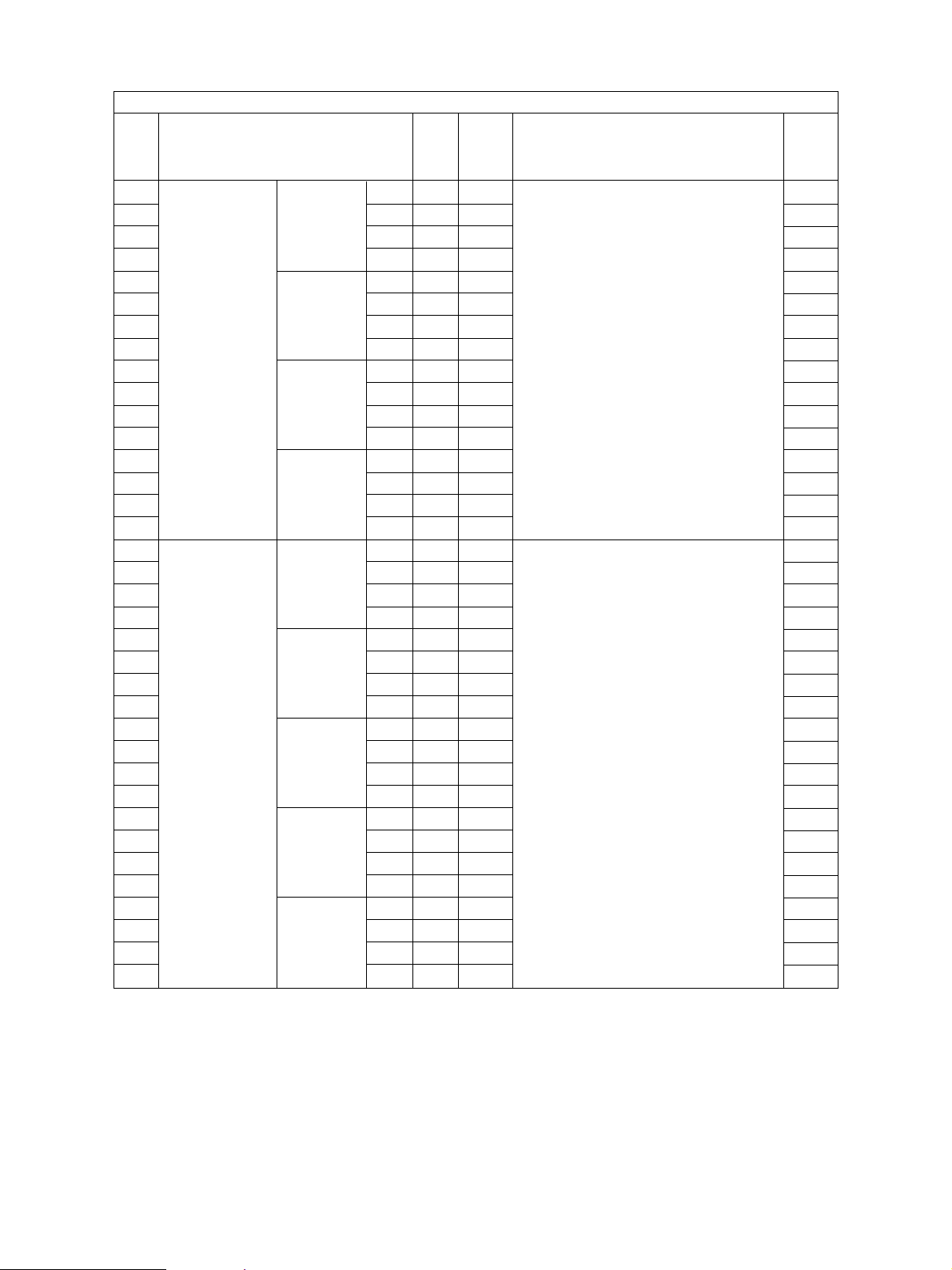
Classification Error code Contents
Paper transport jam E01 Paper leading edge not reaching the exit sensor
inside the copier E02 Paper trailing edge not passing the exit sensor
E03 Paper remaining inside the copier at power ON
EB7 Restart time-out error
Paper feeding jam E11 Paper misfeed from the ADU
E12 Paper misfeed from the bypass tray
E13 Paper misfeed from the 1st cassette
E14 Paper misfeed from the 2nd cassette
E15 Paper misfeed from the 3rd cassette
E16 Paper misfeed from the 4th cassette
E19 Paper misfeed from the LCF
Paper transport jam E21 Paper transport jam from the LCF
(Paper not reaching the registration E22 Paper transport jam from the 1st cassette
sensor after feeding) E23 Paper transport jam from the 2nd cassette
E24 Paper transport jam from the 3rd cassette
E25 Paper transport jam from the 4th cassette
E26 Paper transport jam from the bypass tray
Cover open jam E41 Front cover opened during printing
E42 Side door opened during printing
E43 ADU pulled out during printing
E45 LCF jam access cover opened during printing
E46 Bypass unit opened during printing
Paper transport jam in the ADU and E50 Paper not reaching the ADU
reversing area E51 Paper not reaching the ADU stack
E52 Paper not reaching the ADU path sensor
E54 ADU paper transport jam
February 2002 © TOSHIBA TEC 1 - 1 FC-210/310
ERROR CODES AND SELF-DIAGNOSIS
Page 8
Classification Error code Contents
Original jam in the ADF E71 Original not reaching the aligning sensor
E72 Original not reaching the exit sensor
E73 Original not passing the exit sensor
Paper jam in the finisher E9F Punching jam
EA1 Paper transport delay jam
EA2 Paper transport stop jam
EA3 Paper remaining inside the finisher at power ON
EA4 Finisher front door opened during printing
EA5 Finisher stapling jam
EA6 Finisher early arrival jam
EA8 Saddle stitcher stapling jam
EA9 Saddle stitcher front door opened during printing
EAA Paper remaining in the saddle stitcher at power ON
EAB Saddle stitcher transport stop jam
EAC Saddle stitcher transport delay jam
EAE Finisher receive time-out jam
Special sheet jam EC2 OHP film jams when not fed from bypass tray or 2nd cassette
EC3 OHP film used in non-OHP mode
Drive system related service call C05 ADU motor rotation abnormal
C06 Feed motor rotation abnormal
C0A Developer motor rotation abnormal
Paper feeding system related C11 ADU paper side guide operation abnormal
service call C12 ADU paper end guide operation abnormal
C13 1st cassette tray operation abnormal
C14 2nd cassette tray operation abnormal
C15 3rd cassette tray operation abnormal
C16 4th cassette tray operation abnormal
C18 LCF tray operation abnormal
Scanner related service call C27 Carriage home position sensor not turning OFF within a fixed time
C28 Carriage home position sensor not turning ON within a fixed time
C29 Exposure lamp disconnection detected
FC-210/310
ERROR CODES AND SELF-DIAGNOSIS
1 - 2 February 2002 © TOSHIBA TEC
Page 9
Classification Error code Contents
Copy process related service call C31 Used toner transport motor rotation abnormal
C33 Developer removal shutter abnormal
C35 Transfer belt unit contact/release operation abnormal
C38 Auto-toner error (K)
C39 Auto-toner error (C)
C3A Auto-toner error (M)
C3B Auto-toner error (Y)
C3C Main charger wire cleaning abnormal (K)
C3D Main charger wire cleaning abnormal (C)
C3E Main charger wire cleaning abnormal (M)
C3F Main charger wire cleaning abnormal (Y)
Fuser unit related service call C41 Thermistor or heater abnormal when warming-up is started
C42 Thermistor abnormal after the copier has become ready
C43 Thermistor abnormal during warming-up after abnormality
judgment
C44 Heater abnormal during warming-up after abnormality
judgment
C46 Heater abnormal (low temperature) after the copier has
become ready
C47 Rear thermistor abnormal after the copier has become
ready
C48 Heater abnormal (high temperature)
C7 Error C7
Communications related service call C57 Communications error between LGC-CPU and IPC board
C5A Communications error between LGC-CPU and printer controller
C5B LGC-CPU signal transmission error to IMC-CPU
C5C LGC-CPU signal reception error from IMC-CPU
ADF related service call C72 Aligning sensor automatic adjustment error
C73 EEPROM initializing error
C74 Paper exit sensor automatic adjustment error
Other service call (1) C94 LGC-CPU abnormal
C9A Main memory abnormal
C9B LGC-CPU protocol abnormal
C9D IMC-CPU protocol abnormal
C9E IMC board connection abnormal
February 2002 © TOSHIBA TEC 1 - 3 FC-210/310
ERROR CODES AND SELF-DIAGNOSIS
Page 10
Classification Error code Contents
Laser optical unit related service call CA1 Polygonal motor rotation abnormal
CA2 H-SYNC abnormal
CD1 Laser calibration error (K)
CD2 Laser calibration error (C)
CD3 Laser calibration error (M)
CD4 Laser calibration error (Y)
Finisher related service call CB1 Feed motor abnormal
CB2 Delivery motor abnormal
CB3 Tray lift motor abnormal
CB4 Alignment motor abnormal
CB5 Staple motor abnormal
CB6 Stapler shift motor abnormal
CB7 Height sensor abnormal
CB8 Backup RAM data abnormal
CB9 Saddle stitcher/paper pushing plate motor abnormal
CBA Saddle stitcher/stitcher motor (front) abnormal
CBB Saddle stitcher/stitcher motor (rear) abnormal
CBC Saddle stitcher/alignment motor abnormal
CBD Saddle stitcher/guide motor abnormal
CBE Saddle stitcher/paper folding motor abnormal
CBF Saddle stitcher/paper positioning plate motor abnormal
CD5 Saddle stitcher/sensor connector connection error
CD6 Saddle stitcher/microswitch abnormal
CD7 Communication error between finisher and saddle stitcher
CD9 Swing motor abnormal
CDA Horizontal registration motor abnormal
CDB Punch motor abnormal
Image quality related service call CE1 Image quality sensor abnormal (OFF level)
CE2 Image quality sensor abnormal (no pattern level)
CE4 Image quality control test pattern abnormal
CE5 Temperature/humidity sensor upper-limit abnormal
CE6 Drum thermistor abnormal (Y)
CE9 Drum thermistor abnormal (K)
CF1 Color registration control abnormal
Other service call (2) F07 Communications error between system-CPU and LGC-CPU
F09 Communications error between system-CPU and scanner-CPU
F10 HDD formatting error
F11 Communications error between system-CPU and scanner-CPU
F12 Communications error between system-CPU and scanner-CPU
Image processing related service F51 Communications error between system-CPU and AI board
call during pre-scanning
FC-210/310
ERROR CODES AND SELF-DIAGNOSIS
1 - 4 February 2002 © TOSHIBA TEC
Page 11
<<Error history>>
In the setting mode (08-253), the latest twenty groups of error data will be displayed.
Display example
EA1 01 08 26 17 57 32 64 64 236210000000
Error code
YY MM DD HH MM SS
MMM NNN
3 digits 12 digits (Year is indicated 3 digits 3 digits 12 digits
with its last two digits.)
A Paper source
0: Not selected 1: Bypass feed 2: LCF 3: 1st 4: 2nd 5: 3rd 6: 4th 7: ADU feed
B Paper size code
0: A5/ST 1: A5-R 2: ST-R 3: LT 4: A4 5: B5-R 6: LT-R 7: A4-R 8: OTHER/UNIV
9: B5 A: FOLIO/COMP B: LG C: B4 D: LD E: A3 F: 13"LG H: A6-R I: Card Z: Not selected
C Sort mode / staple mode
0: Non-sort/Non-staple 1: Group 2: Sort 7: Front staple
8: Double staple 9: Rear staple A: Saddle stitch
D ADF mode
0: Unused 1: AUTO FEED (SADF) 2: STACK FEED
E APS / AMS mode
0: Not selected 1: APS 2: AMS
ABCDEFHIJLOP
F Duplex mode
0: Not selected 1: Book 2: Two-sided / Single-sided 4: Two-sided / Duplexed
8: Single-sided / Duplexed
G Unused
H Image shift
0: Unused 1: Book 2: Left 4: Right
I Editing
0: Unused 1: Masking 2: Trimming 3: Mirror image 4: Negative / Positive
J Edge erase / Dual-page
0: Unused 1: Edge erase 2: Dual-page 3: Edge erase & Dual-page
K Unused
L Function
0: Copying 1: Unused 2: Unused 3: Unused 4: Printing 5: Unused
MMM Primary scanning reproduction ratio (Display in hexadecimal)
(Mx256)+(Mx16)+M
NNN Secondary scanning reproduction ratio (Display in hexadecimal)
(Nx256)+(Nx16)+N
O Color mode
0: Auto color 1: Full color 2: Black 3: Monocolor
P AI board
0: Unused 1: Used
February 2002 © TOSHIBA TEC 1 - 5 FC-210/310
ERROR CODES AND SELF-DIAGNOSIS
Page 12
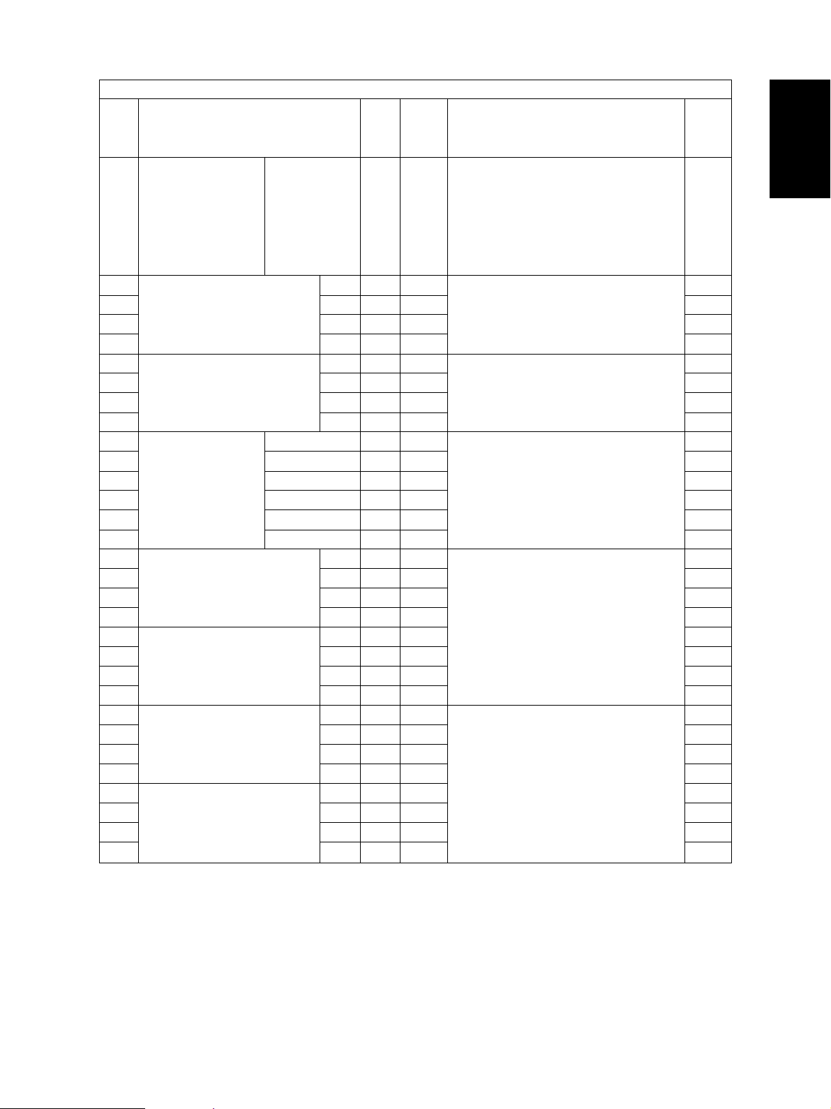
1. 2 Self-Diagnosis Mode
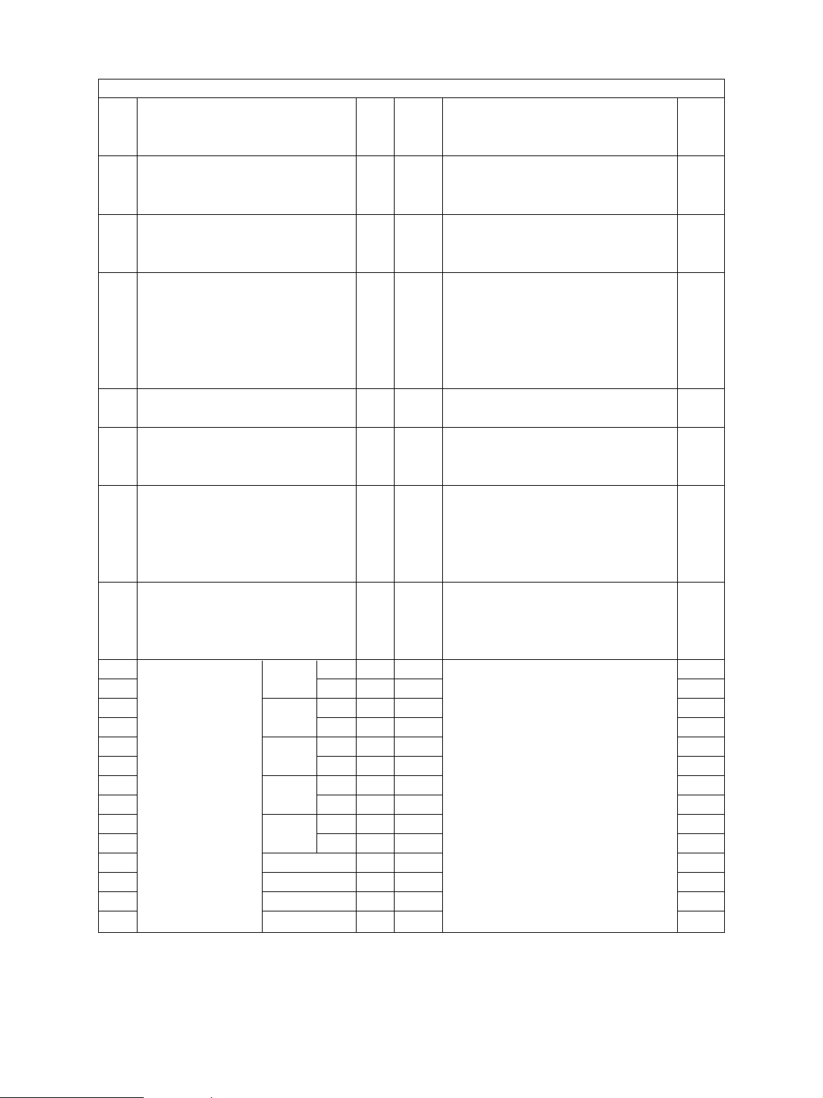
Mode Starting Contents Exit
Control panel check [0]+[1]+[POWER] All control panel LEDs are lit, [CLEAR] or
mode and all LCD pixels are turned [POWER]OFF/ON
ON/OFF repeatedly.
Test mode [0]+[3]+[POWER] Input/output signals are checked.
Test print mode [0]+[4]+[POWER] A test pattern print is made.
Adjustment mode [0]+[5]+[POWER] Adjustment of various items
Setting mode [0]+[8]+[POWER] Setting of various items
List printing mode [9]+[START]+[POWER] Printing of list of 05 and 08 code
data
Note: Starting for various modes:
While pressing simultaneously the two digital keys corresponding to the mode you want to set
(for example, [0] and [5]), turn ON the main switch [POWER].
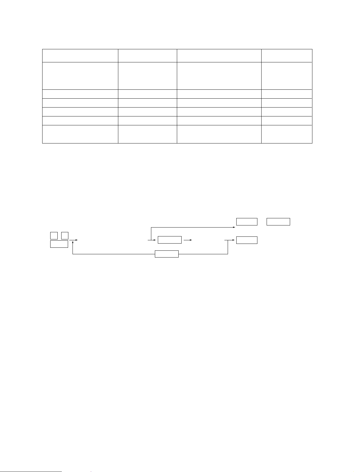
<Operation procedure>
[POWER]OFF/ON
[POWER]OFF/ON
[POWER]OFF/ON
[POWER]OFF/ON
[POWER]OFF/ON
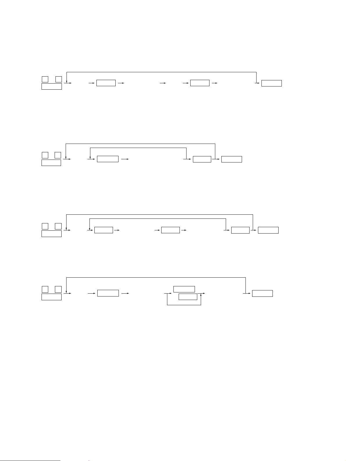
• Control panel check mode (01) :
0 1
Power
(LEDs light/LCD flashes)
START
START
(Check Keys)
CLEAR
(Exit)
CLEAR
(Exit)
POWER OFF/ON
or
Notes: 1. During the “Check keys” state, [CLEAR] alone can exit.
During the “LEDs light/LCD flashes” state, [CLEAR] can clear the mode.
2. Check keys :
Any key with LED (when it is pressed, the LED goes out.)
Any key without LED (when it is pressed, an indication is displayed in the message area.)
• Test mode (03) : Refer to "1.2.1 Input check (Test mode 03)" and "1.2.2 Output check
(Test mode 03)".
• Test print mode (04) : Refer to "1.2.3 Test print mode (04)".
• Adjustment mode (05) : Refer to "1.2.4 Adjustment mode (05)".
• Setting mode (08) : Refer to "1.2.5 Setting mode (08)".
FC-210/310
ERROR CODES AND SELF-DIAGNOSIS
1 - 6 February 2002 © TOSHIBA TEC
Page 13
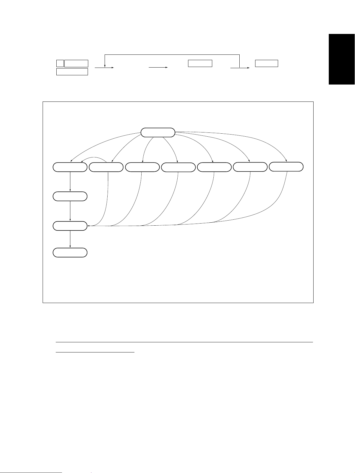
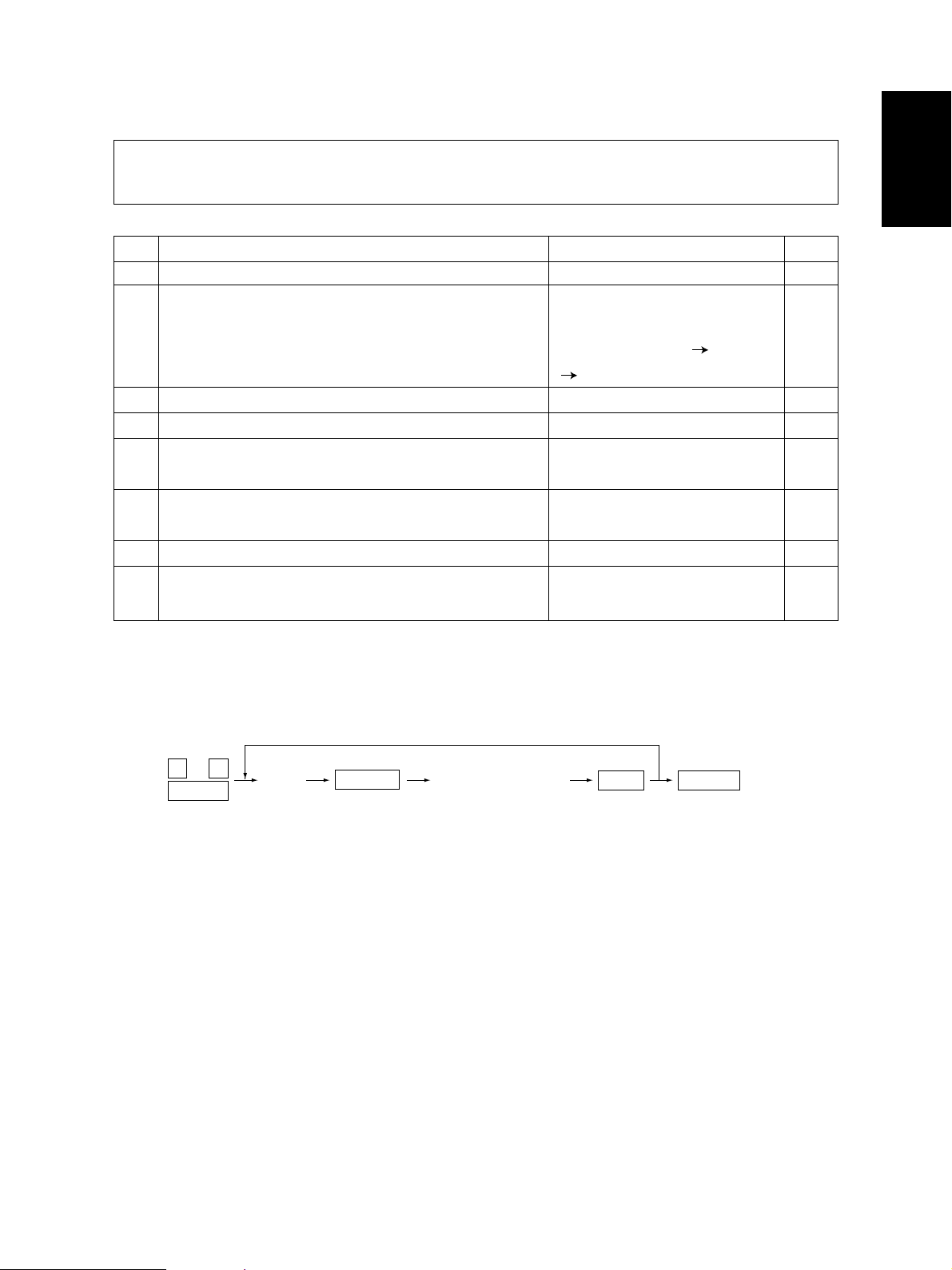
• List printing mode
9
START
POWER
Warming up
Standby
[POWER]OFF/ON
(Code)
101: Adjustment mode (05)
102: Setting mode (08)
Normal
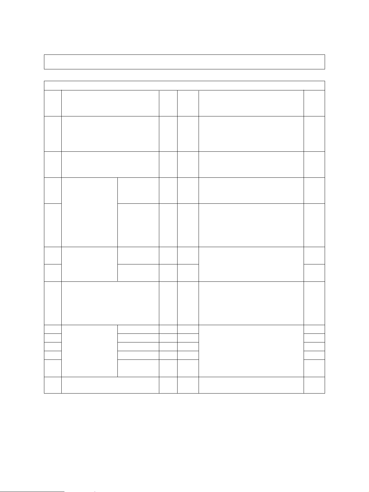
[0][1]
[CLEAR]
Control panel
check mode
*1
START
(Operation is started)
[POWER] ON
[0][3] [0][5] [0][8]
[0][4]
Test print mode
Adjustment mode
POWER OFF/ON
(Exit)
[9][START]
Setting modeTest mode
List printing mode
*2
Hand over to user
T ransition diagram of self-diagnosis mode conditions
*1 : During the activation of the “Control panel check mode”, copying is not possible. But after pressing
[CLEAR] to make the copier ready, you can make copies.
*2 : After having used the self-diagnosis mode, be sure to turn OFF and then ON the power before return-
ing the copier to the customer.
February 2002 © TOSHIBA TEC 1 - 7 FC-210/310
ERROR CODES AND SELF-DIAGNOSIS
Page 14
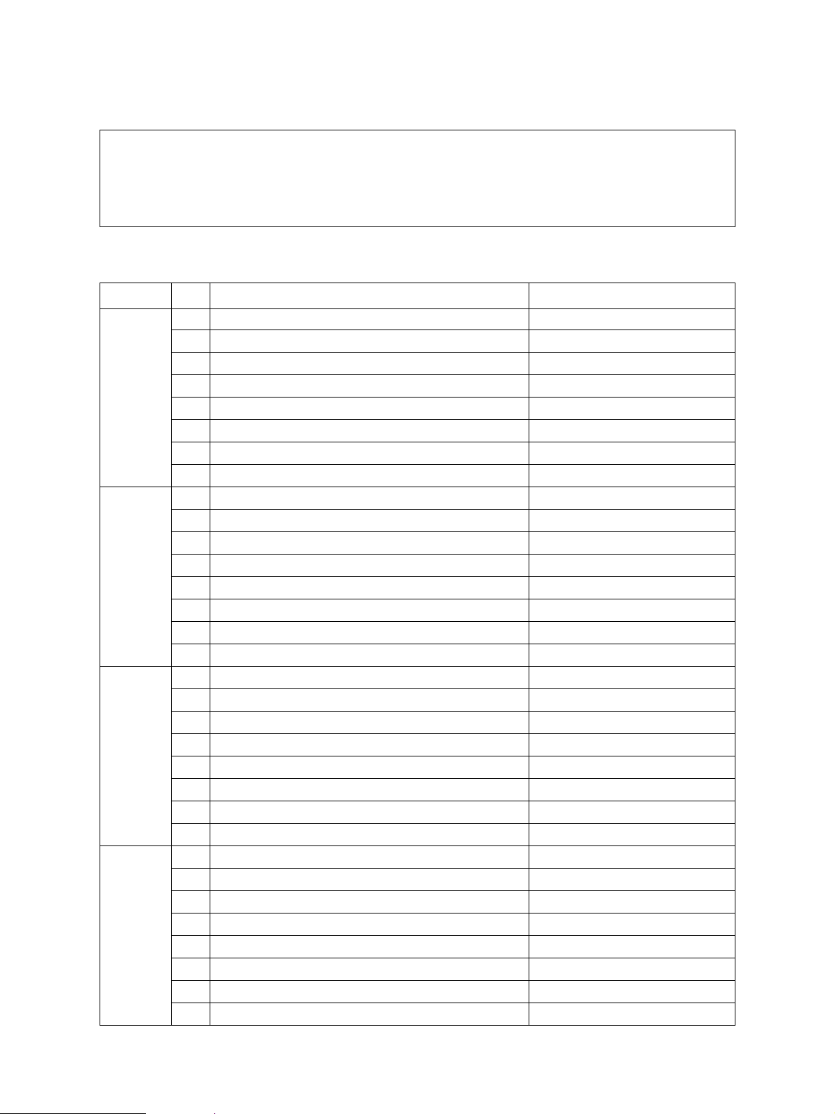
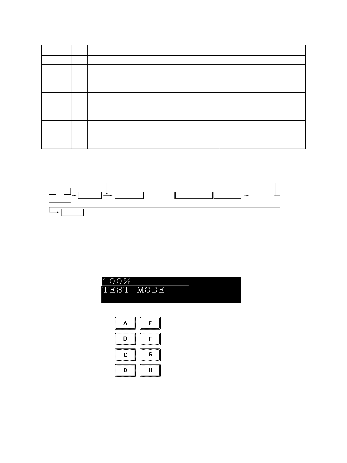
1. 2. 1 Input check (Test mode 03)
The status of each item can be checked by setting ON/OFF of each [FULL COLOR], [AUTO COLOR],
[ENERGY SAVER], and then pressing each of the corresponding digital key in this test mode 03.
Note: When icon is displayed with black letter on white background, it indicates the value is 0, while in
reverse black and white, it indicates the value is 1.
[FULL COLOR]key: OFF, [AUTO COLOR]key: OFF, [ENERGY SAVER]key: OFF
Digital key Icon Item Condition
A —
B —
C —
[1]
[2]
[3]
[4]
D —
E 1st cassette paper-empty sensor 1: No paper
F 1st cassette tray-up limit sensor 1: Tray is upper limit.
G 1st cassette feed-jam sensor 1: Paper present
H 1st cassette detection switch 1: No cassette
A —
B —
C —
D —
E 2nd cassette paper-empty sensor 1: No paper
F 2nd cassette tray-up limit sensor 1: Tray is upper limit.
G 2nd cassette feed-jam sensor 1: Paper present
H 2nd cassette detection switch 1: No cassette
A —
B —
C —
D —
E 3rd cassette paper-empty sensor 1: No paper
F 3rd cassette tray-up limit sensor 1: Tray is upper limit.
G 3rd cassette feed-jam sensor 1: Paper present
H 3rd cassette detection switch 1: No cassette
A —
B —
C —
D —
E 4th cassette paper-empty sensor 1: No paper
F 4th cassette tray-up limit sensor 1: Tray is upper limit.
G 4th cassette feed-jam sensor 1: Paper present
H 4th cassette detection switch 1: No cassette
FC-210/310
ERROR CODES AND SELF-DIAGNOSIS
1 - 8 February 2002 © TOSHIBA TEC
Page 15

Digital key Icon Item Condition
A Bypass paper-width sensor 0 Refer to Table 1.
B Bypass paper-width sensor 1 Refer to Table 1.
C Bypass paper-width sensor 2 Refer to Table 1.
[5]
[6]
[7]
[8]
D —
E Bypass paper sensor 1: No paper
F Bypass unit open/close switch 1: Unit is opened.
G Side door open/close switch 1: Side door is opened.
H Bypass unit is installed or not 0: Unit is installed.
A LCF paper-empty sensor 1: No paper
B LCF lower-limit sensor 1: Tray limit (lower)
C LCF tray-up sensor 1: Tray limit (upper)
D LCF tray-down switch 0: Switch is ON.
E LCF paper supply door sensor 1: Door is opened.
F LCF is installed or not 0: LCF is installed.
G ADU motor rotation status 0: Normal rotation
(Motor is rotating by output check 03)
H ADU is installed or not 0: ADU is installed.
A ADU paper-jam sensor 1: Paper present
B ADU paper-empty sensor 0: No paper
C ADU end switch 1: End guide is at home position.
D ADU side switch 1: Side guide is at home position.
E —
F —
G Key copy counter is installed or not 0: Key copy counter is installed.
H —
A Developer removal shutter home position sensor 0: Shutter is at closed position.
B —
C Transfer belt unit is installed or not 0: Unit is installed.
D —
E —
F Developer motor rotation status 0: Normal rotation
(Motor is rotating by output check 03)
G Transfer belt limit switch 0: Transfer belt is in black mode position.
H Transfer belt home position switch 0: Transfer belt is in color mode position.
February 2002 © TOSHIBA TEC 1 - 9 FC-210/310
ERROR CODES AND SELF-DIAGNOSIS
Page 16
Digital key Icon Item Condition
A External printer controller power ON/OFF 0: Controller power ON
B —
C —
[9]
[0]
D Front cover switch 1: Front cover is opened.
E OHP sensor 0: Opaque paper is installed.
F —
G Registration sensor 1 : Paper present
H IPC board (Finisher installation kit) is installed or not 0: Board is installed.
A ADU path sensor 1: Paper present
B —
C Exit sensor 1: Paper present
D Paper-exit unit open/close switch 1: Paper-exit unit is opened.
E Toner bag limit sensor 1: Used toner full
F —
G —
H —
Table 1. Relation between bypass paper-width sensor status and paper-width size.
Bypass paper-width sensor
210
1 0 0 A3/LD
0 1 0 A4-R/LT-R
1 0 1 A5-R/ST-R
0 1 1 Card size
0 0 0 B4/LG
1 1 0 B5-R
Paper-width size
FC-210/310
ERROR CODES AND SELF-DIAGNOSIS
1 - 10 February 2002 © TOSHIBA TEC
Page 17
[FULL COLOR]key: OFF, [AUTO COLOR]key: OFF, [ENERGY SAVER]key: ON
Digital key Icon Item Condition
A —
B —
C —
[1]
[2]
[3]
[4]
D —
E —
F —
G —
H —
A Developer cartridge Y is installed or not 0: Cartirdge is installed.
B Developer cartridge M is installed or not 0: Cartirdge is installed.
C Developer cartridge C is installed or not 0: Cartirdge is installed.
D Developer cartridge K is installed or not 0: Cartirdge is installed.
E Processing unit is installed or not 0: Unit is installed.
F Fuser unit is installed or not 0: Unit is installed.
G —
H —
A Wire cleaner home position switch Y 0: Cleaning pad is at home position.
B Wire cleaner home position switch M 0: Cleaning pad is at home position.
C Wire cleaner home position switch C 0: Cleaning pad is at home position.
D Wire cleaner home position switch K 0: Cleaning pad is at home position.
E Wire cleaner limit switch Y 0: Cleaning pad is at limit position.
F Wire cleaner limit switch M 0: Cleaning pad is at limit position.
G Wire cleaner limit switch C 0: Cleaning pad is at limit position.
H Wire cleaner limit switch K 0: Cleaning pad is at limit position.
A —
B —
C —
D —
E —
F —
G —
H —
February 2002 © TOSHIBA TEC 1 - 11 FC-210/310
ERROR CODES AND SELF-DIAGNOSIS
Page 18
Digital key Icon Item Condition
A —
B —
C —
[5]
[6]
[7] ——
[8] — Upper heat roller thermistor (center) check
[9] — Upper heat roller thermistor (rear) check
[0] — Lower heat roller thermistor (center) check
D —
E —
F —
G —
H —
A —
B —
C —
D —
E —
F —
G Front cover, paper-exit unit open/close check 1: Cover/unit is opened.
H Polygonal motor rotation status 0: Normal rotation
(Motor is rotating by output check 03)
Thermistor output value is displayed with 8 bits.
Thermistor output value is displayed with 8 bits.
Thermistor output value is displayed with 8 bits.
[FULL COLOR]key: OFF, [AUTO COLOR]key: ON, [ENERGY SAVER]key: OFF
Digital key Icon Item Condition
[1] — Lower heat roller thermistor (rear) check
[2] — Temperature sensor check
[3] — Humidity sensor check
[4] — Drum thermistor Y check
[5] ——
[6] ——
[7] — Drum thermistor K check
[8] ——
[9] ——
[0] ——
Thermistor output value is displayed with 8 bits.
Sensor output value is displayed with 8 bits.
Sensor output value is displayed with 8 bits.
Thermistor output value is displayed with 8 bits.
Thermistor output value is displayed with 8 bits.
FC-210/310
ERROR CODES AND SELF-DIAGNOSIS
1 - 12 February 2002 © TOSHIBA TEC
Page 19
[FULL COLOR]key: OFF, [AUTO COLOR]key: ON, [ENERGY SAVER]key: ON
Digital key Icon Item Condition
[1] ——
[2] — Color registration sensor (front) "0" is displayed with reflection at
(Sensor LED is turned ON by output check 03.) transfer belt.
[3] — Color registration sensor (rear) "0" is displayed with reflection at
(Sensor LED is turned ON by output check 03.) transfer belt.
[4] — Image quality sensor
[5] ——
A ADF aligning sensor 1: Original present
B ADF exit sensor 1: Original present
C ADF open/close sensor 1: ADF is opened.
[6]
[7]
[8]
[9] — SCM board input 24V check Output value is displayed with 8 bits.
[0] ——
D ADF empty sensor 1: Original present
E ADF size sensor 1
F —
G ADF size sensor 2
H ADF unit is installed or not 1: ADF unit is installed.
A —
B —
C —
D —
E —
F Carriage home position sensor 1: Carriages are at home position.
G —
H Platen sensor 1: Platen cover is closed.
A —
B —
C —
D APS sensor (APS-R) 1: Original present
E APS sensor (APS-C) 1: Original present
F APS sensor (APS-3) 1: Original present
G APS sensor (APS-2) (for A4 series) 1: Original present
H APS sensor (APS-1) 1: Original present
Sensor output value is displayed with 10 bits.
February 2002 © TOSHIBA TEC 1 - 13 FC-210/310
ERROR CODES AND SELF-DIAGNOSIS
Page 20
[FULL COLOR]key: ON, [AUTO COLOR]key: OFF, [ENERGY SAVER]key: OFF
Digital key Icon Item Condition
[1] — Auto-toner sensor Y
[2] — Auto-toner sensor M
[3] — Auto-toner sensor C
[4] — Auto-toner sensor K
[5] ——
[6] ——
[7] ——
[8] ——
[9] ——
[0] ——
Sensor output value is displayed with 8 bits.
Sensor output value is displayed with 8 bits.
Sensor output value is displayed with 8 bits.
Sensor output value is displayed with 8 bits.
<Operation procedure>
0 3
POWER
POWER OFF/ON
Note: After initialization, the copier goes into the test mode.
START
(Exit)
(
FULL COLOR
AUTO COLOR
ENERGY SAVER Digital keys
)
(LCD ON)
FC-210/310
Note: When icon is displayed with white letter on black background on the control
panel, it indicates the value is 1.
ERROR CODES AND SELF-DIAGNOSIS
1 - 14 February 2002 © TOSHIBA TEC
Page 21
1. 2. 2 Output check (Test mode 03)
Output signal status can be checked by entering the following code in the test mode 03.
Code Function Code Function Procedure
150 All output OFF 1
101 Drum motor and transfer belt motor rotation 151 Code No. 101 function OFF 1
with normal printing speed ON
102 Drum motor and transfer belt motor rotation 152 Code No. 102 function OFF 1
with OHP printing speed (low) ON
103 Paper feed motor ON 153 Code No. 103 function OFF 1
104 Fuser motor ON 154 Code No. 104 function OFF 1
105 Developer motor (color mode) ON 155 Code No. 105 function OFF 1
106 Developer motor (black mode) ON 156 Code No. 106 function OFF 1
107 Registration motor ON 157 Code No. 107 function OFF 1
108 Used toner transport motor ON 158 Code No. 108 function OFF 1
109 ADU motor ON 159 Code No. 109 function OFF 1
110 Toner motor Y ON 160 Code No. 110 function OFF 1
111 Toner motor M ON 161 Code No. 111 function OFF 1
112 Toner motor C ON 162 Code No. 112 function OFF 1
113 Toner motor K ON 163 Code No. 113 function OFF 1
114 Image quality sensor shutter solenoid ON 164 Code No. 114 function OFF 1
130 Polygonal motor standby speed ON 180 Code No. 130 function OFF 1
131 Polygonal motor normal speed ON 181 Code No. 131 function OFF 1
132 Image quality sensor LED ON 182 Code No. 132 function OFF 1
133 Color registration sensor LED (front) ON 183 Code No. 133 function OFF 1
134 Color registration sensor LED (rear) ON 184 Code No. 134 function OFF 1
135
Image quality sensor mode switching ON (Black mode)
201 1st cassette feed clutch ON/OFF 3
202 2nd cassette feed clutch ON/OFF 3
203 3rd cassette feed clutch ON/OFF 3
204 4th cassette feed clutch ON/OFF 3
205 Feed path clutch ON/OFF 2
206 Bypass feed clutch ON/OFF 3
207 1st cassette tray-up motor ON (tray goes up) 2
208 2nd cassette tray-up motor ON (tray goes up) 2
209 3rd cassette tray-up motor ON (tray goes up) 2
210 4th cassette tray-up motor ON (tray goes up) 2
211 Paper-exit gate solenoid ON/OFF 3
213 Ozone exhaust fan motor ON/OFF 3
185
Code No. 135 function OFF (Color mode)
1
February 2002 © TOSHIBA TEC 1 - 15 FC-210/310
ERROR CODES AND SELF-DIAGNOSIS
Page 22
Code Function Procedure
214 Fuser exhaust fan motor Low/High speed 3
215 PC board cooling fan motor ON/OFF 3
216 Wire cleaner drive motor Y CW/CCW (continuous reciprocating) 2
217 Wire cleaner drive motor M CW/CCW (continuous reciprocating) 2
218 Wire cleaner drive motor C CW/CCW (continuous reciprocating) 2
219 Wire cleaner drive motor K CW/CCW (continuous reciprocating) 2
220 Transfer belt contact/release motor CW/CCW (continuous reciprocating) 2
223 LCF paper feed motor ON/OFF 3
224 LCF tray motor ON/OFF 2
225 ADU feed clutch ON/OFF 3
226 ADU gate solenoid ON/OFF 3
227 ADU side motor ON/OFF 3
228 ADU end motor ON/OFF 3
229 Pre-feed clutch (front) ON/OFF 3
230 Pre-feed clutch (rear) ON/OFF 3
235 Main charger Y ON/OFF 3
236 Main charger M ON/OFF 3
237 Main charger C ON/OFF 3
238 Main charger K ON/OFF 3
243 Developer bias (Y) DC(-) ON/OFF 3
244 Developer bias (M) DC(-) ON/OFF 3
245 Developer bias (C) DC(-) ON/OFF 3
246 Developer bias (K) DC(-) ON/OFF 3
247 Developer bias (Y) AC ON/OFF 3
248 Developer bias (M) AC ON/OFF 3
249 Developer bias (C) AC ON/OFF 3
250 Developer bias (K) AC ON/OFF 3
251 Cleaning blade bias (Y) DC ON/OFF 3
252 Cleaning blade bias (M) DC ON/OFF 3
253 Cleaning blade bias (C) DC ON/OFF 3
254 Cleaning blade bias (K) DC ON/OFF 3
255 Transfer roller bias (Y) ON/OFF 3
256 Transfer roller bias (M) ON/OFF 3
257 Transfer roller bias (C) ON/OFF 3
258 Transfer roller bias (K) ON/OFF 3
259 Suction charger ON/OFF 3
260 Discharge lamp Y ON/OFF 3
261 Discharge lamp M ON/OFF 3
262 Discharge lamp C ON/OFF 3
FC-210/310
ERROR CODES AND SELF-DIAGNOSIS
1 - 16 February 2002 © TOSHIBA TEC
Page 23
Code Function Procedure
263 Discharge lamp K ON/OFF 3
280 Laser (Y) ON/OFF 3
281 Laser (M) ON/OFF 3
282 Laser (C) ON/OFF 3
283 Laser (K) ON/OFF 3
300 Carriage fan motor rotation at standby speed (high speed) ON/OFF 3
301 Carriage fan motor rotation at normal speed (low speed) ON/OFF 3
302 SCM fan motor Low/High speed 3
304 Scanner exposure lamp ON/OFF 4
331 ADF pick-up roller rotation ON/OFF 3
332 ADF aligning roller rotation ON/OFF 3
333 ADF transport belt CW rotation ON/OFF 3
334 ADF transport belt CCW rotation ON/OFF 3
351 Scan motor (carriages reciprocating once) 2
352 Document motor (indicator reciprocating once) 2
February 2002 © TOSHIBA TEC 1 - 17 FC-210/310
ERROR CODES AND SELF-DIAGNOSIS
Page 24
<Operation procedure>
Procedure 1
0 3
POWER
Procedure 2
0 3
POWER
Procedure 3
0 3
POWER
(Code)
(Code)
(Code)
START START
START
START START
(One-direction operation)
(Operation ON) (Operation OFF)
(Code)(Operation ON)
(Operation OFF)
POWER OFF/ONCLEAR
(Exit)
POWER OFF/ON
(Exit)
POWER OFF/ONCLEAR
(Exit)
Procedure 4
0 3
POWER
FC-210/310
(Code)
START
(Operation ON) (Operation OFF)
ERROR CODES AND SELF-DIAGNOSIS
START
CLEAR
or
6 sec. later
POWER OFF/ON
(Exit)
1 - 18 February 2002 © TOSHIBA TEC
Page 25
1. 2. 3 Test print mode (04)
In the test print mode (04), you can print each test pattern by entering its corresponding code as
follows.
Code Types of test pattern Remarks
14 Gamma table check pattern To check gradation A3/LD
204 Grid pattern (Printer reproduction ratio/Registration Pattern width: 1 dot, Pitch: 5mm A3/LD
adjustment pattern) (same as the grid pattern printed
by adjustment mode
[PRINTER/NETWORK])
219 6% test pattern A4/LT
220 8% test pattern A4/LT
230 Gradation check pattern (2 pixels standard) Pattern width: 10mm, A3/LD
32 gradation steps
231 Gradation check pattern (3 pixels standard) Pattern width: 10mm, A3/LD
32 gradation steps
234 Halftone A3/LD
270 Image quality control test patten To check image quality control A3/LD
Note: Full color (YMCK) mode is not available in 230, 231 and 234.
[1]
Paper size
<Operation procedure>
0 4
POWER
Notes:1. When an error has occurred, it is indicated, but the recovery operation is not performed. So, turn the
power OFF and then back ON to clear the error.
2. During test printing, when "Wait adding toner" is displayed, the [STOP] key is disabled.
February 2002 © TOSHIBA TEC 1 - 19 FC-210/310
(Code)
START
(Continuous test
print operation)
POWER OFF/ONSTOP
(Exit)
ERROR CODES AND SELF-DIAGNOSIS
Page 26
1. 2. 4 Adjustment mode (05)
In the adjustment mode (05), the following adjustment items can be corrected, changed or checked.
*The numbers after hyphens under the code columns stand for sub-codes.
Adjustment mode (05)
Accep-
Code Description/Mode
104 Reproduction ratio adjustment of 128 1~255 When the value increases by 1, the re- 1
secondary-scanning direction production ratio in the secondary-scan-
(scanner section) ning direction (vertical paper feeding di-
105 Image location adjustment of 128 85~171 When the value increases by 1, the 1
secondary-scanning direction image shifts by approx. 0.1213mm to(scanner section) ward the trailing edge of the paper.
106 Image location For regular 180 5~251 When the value increases by 1, the 1
adjustment of prima- copy mode image shifts by approx. 0.042mm toward
ry-scanning direction the front side of the paper (machine).
108 (scanner section) For full image 133 5~251 When you enter a value,which is 47 1
copy mode steps (equivalent to 2mm) smaller than
135 RADF single-sided 8 0~15 Changes the position where the original 1
original stop position stops. When the value increases by 1,
136 two-sided 8 0~15 the original stop position shifts by 1mm 1
137 RADF sensor automatic adjustment – – By pressing the START key, WAIT is dis- 6
and EEPROM initialization played while the automatic adjustment
200 Automatic filling of All (Y, M, C, K) – 0~255 Fills the developer from the developer 5
201 developer material Y – 0~255 cartridge (about 3 min.) and then adjusts 5
202 and automatic ad- M – 0~255 the auto-toner sensor output to set in the 5
203 justment of the auto- C – 0~255 range of 3.50~4.50V (about 2 min.). 5
204 toner sensor K – 0~255 (As the value increases, the sensor out- 5
213 Display of auto-toner sensor output 0 0~1023 D isplays the auto-toner sensor output 10
Default
table Contents
Value
rection) increases by approx. 0.1522%.
the set value of [106], the rear original
edge and the front copy edge match
(0.042mm/step).
away from the original scale.
is performed. This adjustment should be
carried out when EEPROM, RADF PC
board or sensors are replaced.
put increases correspondingly.)
value.
Proce-
dure
FC-210/310
ERROR CODES AND SELF-DIAGNOSIS
1 - 20 February 2002 © TOSHIBA TEC
Page 27
Adjustment mode (05)
Accep-
Code Description/Mode
221 Automatic filling of Color (Y, M, C) – 0~255 Fills the developer from the developer 5
developer material cartridge (about 3 min.) and then adjusts
and automatic ad- the auto-toner sensor output to set in the
justment of the auto- range of 3.50~4.50V (about 2 min.).
toner sensor (As the value increases, the sensor out-
223 Developer bias DC (–) Y 136 0~255 As the value increases, the transformer 1
224 output adjustment M 136 0~255 output increases. The adjustment value 1
225 C 136 0~255 becomes effective only when the setting 1
226 K 136 0~255 mode (08-400,401,409) is 0 (disabled). 1
241 Main charger grid bias Y 120 0~255 As the value increases, the transformer 1
242 output adjustment M 120 0~255 output increases. The adjustment value 1
243 C 120 0~255 becomes effective only when the setting 1
244 K 120 0~255 mode (08-400,401,409) is 0 (disabled). 1
245 Automatic adjust- All (Y,M,C,K) – 0~255 Auto-toner sensor output is adjusted 5
246 ment of the auto- Y – 0~255 to set the output range within 3.50~ 5
247 toner sensor M – 0~255 4.50V automatically (about 2 min.). As 5
248 C – 0~255 the value increases, the sensor ouptut 5
249 K – 0~255 increases correspondingly.) (No deve- 5
250 Color (Y,M,C) – 0~255 loper filling is carried out.) 5
252-0 Main charger bias Y 250 0~999 Actual output voltage of main charger 4
252-1 output voltage 1 (lower) M 250 0~999 grid bias. After replacing the main high- 4
252-2 C 250 0~999 voltage transformer, enter the value ac- 4
252-3 K 250 0~999 cording to the supplementary data sheet. 4
253-0 Main charger bias Y 900 0~999 4
253-1 output voltage 2 (upper) M 900 0~999 4
253-2 C 900 0~999 4
253-3 K 900 0~999 4
257-0 Developer bias DC(-) Y 100 0~999 Actual output voltage of the developer 4
257-1 output voltage 1 (lower) M 100 0~999 bias. After replacing the main high- 4
257-2 C 100 0~999 voltage transformer, enter the value ac- 4
257-3 K 100 0~999 cording to the supplementary data sheet. 4
258-0 Developer bias DC(-) Y 700 0~999 4
258-1 output voltage 2 (upper) M 700 0~999 4
258-2 C 700 0~999 4
258-3 K 700 0~999 4
Default
table Contents
Value
put increases correspondingly.)
Proce-
dure
February 2002 © TOSHIBA TEC 1 - 21 FC-210/310
ERROR CODES AND SELF-DIAGNOSIS
Page 28
Adjustment mode (05)
Accep-
Code Description/Mode
318 Transfer bias
319 output adjust- mode / Thin M 59 0~255 set. The higher the value, the larger the 1
320 ment paper mode C 5 9 0~255 transformer output becomes. The adjust- 1
321 (Full color) K 59 0~255 ment value becomes effective only when 1
326
327 mode M 59 0~255 (disabled). 1
328 C 59 0~255 1
329 K 59 0~255 1
330 OHP mode Y 59 0~255 1
331 M 99 0~255 1
332 C 109 0~255 1
333 K 139 0~255 1
334 Thick paper 2 Y 69 0~255 1
335 mode M 69 0~255 1
336 C 69 0~255 1
337 K 69 0~255 1
356-0 Transfer bias
356-1 offset adjust- mode / Thin M 4 0~8 set. 4
356-2 ment paper mode C 4 0~8 0: -400V 1: -300V 2: -200V 4
356-3 K 4 0~8 3: -100V 4: 0V 5: +100V 4
357-0
357-1 mode M 4 0~8 4
357-2 C 4 0~8 4
357-3 K 4 0~8 4
358-0 Thick paper 2 Y 4 0~8 4
358-1 mode M 4 0~8 4
358-2 C 4 0~8 4
358-3 K 4 0~8 4
359-0 Thick paper 3 Y 4 0~8 4
359-1 mode M 4 0~8 4
359-2 C 4 0~8 4
359-3 K 4 0~8 4
360-0 OHP mode Y 4 0~8 4
360-1 M 4 0~8 4
360-2 C 4 0~8 4
360-3 K 4 0~8 4
Normal paper
Thick paper
Normal paper
Thick paper
1 Y 59 0~255 the setting mode (08-400,401,409)is 0 1
1 Y 4 0~8 6: +200V 7: +300V 8: +400V 4
Default
Y 59 0~255 The bias value of the transfer roller is 1
Y 4 0~8 The offset value of the transfer bias is 4
table Contents
Value
Proce-
dure
FC-210/310
ERROR CODES AND SELF-DIAGNOSIS
1 - 22 February 2002 © TOSHIBA TEC
Page 29

Adjustment mode (05)
Accep-
Code Description/Mode
361 Transfer bias Normal paper K 4 9 0~255 The bias value of the transfer roller is 1
output adjust- mode / Thin set. The higher the value, the larger the
ment (Black) paper mode transformer output becomes. This ad-
363 Thick paper 1 K 4 9 0~255 justment value becomes effective only 1
mode when the setting mode (08-400, 401,
364 OHP mode K 69 0~255 409) is 0 (disabled). 1
365 Thick paper 2 K 5 9 0~255 1
mode
367-0 Transfer bias output Y 589 0~5000 Actual output voltage of the transfer 4
367-1 voltage 1 (lower) M 589 0~5000 roller bias. After replacing the transfer 4
367-2 C 589 0~5000 transformer, enter the value according to 4
367-3 K 589 0~5000 the supplementary data sheet. 4
368-0 Transfer bias output Y 3929 0~5000 4
368-1 voltage 2 (upper) M 3929 0~5000 4
368-2 C 3929 0~5000 4
368-3 K 4715 0~5000 4
381 Transfer bias output Thick Y 89 0~255 The bias value of the transfer roller is 1
382 adjustment paper 3 M 89 0~255 set. The higher the value, the larger the 1
383 (Full color) mode C 89 0~255 transformer output becomes. The ad- 1
384 K 89 0~255 justment value becomes effective only 1
385 Transfer bias output Thick K 79 0~255 when the setting mode(08-400, 401, 1
adjustment paper 3 409) is 0 (disabled).
(Black) mode
391 Automatic removing Color (Y, M, C) – – The developer material in the developer 6
392 of developer mate- K – – unit is removed into the toner bag. 6
rial
400 Reproduction ratio adjustment of 1222 1209~ When the value increases by 1, the re- 1
primary-scanning direction 1235 production ratio in the primary-scanning
(Fine adjustment of polygonal motor direction (horizontal paper feeding di-
rotation speed) rection) decreases by approx. 0.082%.
401 Reproduction ratio adjustment of 1787 1608~ When the value increases by 1, the re- 1
secondary-scanning direction 1965 production ratio in the secondary-scan-
(Fine adjustment of drum motor/ ning direction (vertical paper feeding di-
transfer belt motor rotation speed) rection) decreases by approx. 0.074%.
Default
table Contents
Value
(If the values of this code 400 is changed, the values of code 05-401,402,403,
404,410 and 474 are optimized.)
(If the values of this code 401 is changed, the values of code 05-402,403,404,
410 and 474 are optimized.)
Proce-
dure
February 2002 © TOSHIBA TEC 1 - 23 FC-210/310
ERROR CODES AND SELF-DIAGNOSIS
Page 30
Adjustment mode (05)
Accep-
Code Description/Mode
402 Fine adjustment of 3767 0~ When the value increases by 1, the rota- 1
fuser motor rotation speed 65535 tion speed of fuser motor decreases
404 Fine adjustment of 9832 0~ When the value increases by 1, the rota- 1
feed motor rotation speed 65535 tion speed of the paper feed motor de-
406 Registration motor speed adjustment – – The paper transport speed of registra- 15
407 Forced performing of – – Performs the color registration control. 6
color registration control
408 Correction of fuser motor speed 0 0~20 In the thick paper 3 mode, when the 1
(For the Thick paper 3 mode ) value increases by 1, the fuser motor
410 Fine adjustment of 2853 2567~ When the value increases by 1, the re- 1
registration motor rotation speed 3138 gistration motor rotation speed decreases
428 Adjustment of image trailing edge 160 0~255 When the value increases by 1, the mar- 1
margin gin at the trailing edge along the paper
439 Paper aligning 1st Long 20 0~40 When the value increases by 1, the ali- 1
440 amount adjustment cassette Short 25 0~40 gning amount increases by about 1
441 2nd Long 20 0~40 0.8mm. 1
442 cassette Short 25 0~40 1
443 3rd Long 20 0~40 Notes: 1
444 cassette Short 25 0~40 Long (= Long size paper) : 1
445 4th Long 20 0~40 Paper length 330mm or longer 1
446 cassette Short 25 0~40 (A3/LD/A3 wide/FULL BLEED) 1
447 ADU Long 20 0~40 Short (= Short size paper) : 1
448 Short 25 0~40 Paper length 220mm ~ 329mm 1
449 LCF 25 0~40 1
450 Bypass feed 35 0~40 1
451 Thick paper 2 40 0~50 1
452 Thick paper 3 40 0~50 1
Default
table Contents
Value
by 0.026%.
creases by 0.023%.
tion roller in relation to the image printing speed is set at the optimum value.
(If the value of this code 406 is performed, the values of the code 05-404 and
410 are optimized.)
rotation speed decreases by 0.026%.
by 0.035%. (If the value of this code 410
is performed, the value of the code 05-404
is optimized.
feeding direction becomes narrower by
approx. 0.042mm.
Proce-
dure
FC-210/310
ERROR CODES AND SELF-DIAGNOSIS
1 - 24 February 2002 © TOSHIBA TEC
Page 31

Adjustment mode (05)
Accep-
Code Description/Mode
461 Color registration status display 0 0~255 The value of Y(0) shows the error status 10
470 Adjustment of primary-scan- K 100 0~255 When the value increases by 1, the im- 1
ning laser writing start position age shifts by approx. 0.042mm toward
474 Adjustment of secondary-scan- 8 1~15 When the value increases by 1, the im- 1
ning laser writing start position age shifts by approx. 0.6mm toward the
482 Reproduction ratio adjustment of 127 112~ When the value increases by 1, the re- 1
the primary-scanning direction 142 production ratio of the primary-scanning
(scanner section) direction (paper feeding in horizontal
491 Adjustment of the Thick paper 3 9 0~14 When the value increases by 1, the time 1
pushing amount bypass feeding period the bypass feed roller is driven
from behind when the paper has started to be trans-
492 Paper aligning amout adjustment 40 0~50 When the value increases by 1, the ali- 1
(OHP bypass feeding) gning amount increases by about
493 Adjustment of the OHP 9 0~14 When the value increases by 1, the time 1
pushing amount bypass feeding period the bypass feed roller is driven
from behind when the paper has started to be trans-
494 LCF 0 0~12 When the value increases by 1, the time 1
495 Thin paper 0 0~14 When the value increases by 1, the time 1
bypass feeding period the bypass feed roller is driven
496 Normal paper 9 0~14 when the paper has started to be trans- 1
bypass feeding ported from the registration section in-
497 Thick paper 1 9 0~14 creases by 7ms. 1
bypass feeding
498 Thick paper 2 9 0~14 1
bypass feeding
Default
table Contents
Value
of the color registration sensor.
0 / 16 or above: Normal
1~14: Data abnormal (sensor normal)
15: Color registration pattern reading
error
the right side of paper feed direction.
leading edge of paper feed direction.
direction) decreases by 0.082%.
ported from the registration section increases by 7ms.
0.8mm.
ported from the registration section increases by 7ms.
period the LCF feed roller is driven
when the paper has started to be transported from the pre-feed roller section increases by 50ms.
Proce-
dure
February 2002 © TOSHIBA TEC 1 - 25 FC-210/310
ERROR CODES AND SELF-DIAGNOSIS
Page 32

Adjustment mode (05)
Accep-
Code Description/Mode
550 Density
551 adjustment Text 128 0~255 made at center density become darker. 1
552 "Manual density"
553 fine adjustment Photo 128 0~255 1
554 (center setting) Map 128 0~255 1
555
556 Text 128 0~255 1
557
558 Photo 128 0~255 1
559 Map 128 0~255 1
560 Density
561 adjustment Text 20 0~255 made at the “dark” side become darker. 1
562 "Manual density"
563 fine adjustment Photo 20 0~255 1
564 (darker setting) Map 20 0~255 1
565
566 Text 20 0~255 1
567
568 Photo 20 0~255 1
569 Map 20 0~255 1
570 Density
571 adjustment Text 20 0~255 made at the “light” side become lighter. 1
572 "Manual density"
573 fine adjustment Photo 20 0~255 1
574 (lighter setting) Map 20 0~255 1
575
576 Text 20 0~255 1
577
578 Photo 20 0~255 1
579 Map 20 0~255 1
580 Density
581 adjustment Text 128 0~255 come darker. 1
582 "Automatic
583 density" fine Photo 128 0~255 1
584 adjustment Map 128 0~255 1
585
586 Text 128 0~255 1
587
588
589
Full color Text/Photo
Printed image
Black Text/Photo
Printed image
Full color Text/Photo
Printed image
Black Text/Photo
Printed image
Full color Text/Photo
Printed image
Black Text/Photo
Printed image
Full color Text/Photo
Printed image
Black Text/Photo
Printed image
Photo 128 0~255 1
Map 128 0~255 1
Default
table Contents
Value
128 0~255 When the value increases, images 1
128 0~255 1
128 0~255 1
128 0~255 1
20 0~255 When the value increases, images 1
20 0~255 1
20 0~255 1
20 0~255 1
20 0~255 When the value increases, images 1
20 0~255 1
20 0~255 1
20 0~255 1
128 0~255 When the value increases, images be- 1
128 0~255 1
128 0~255 1
128 0~255 1
Proce-
dure
FC-210/310
ERROR CODES AND SELF-DIAGNOSIS
1 - 26 February 2002 © TOSHIBA TEC
Page 33

Adjustment mode (05)
Accep-
Code Description/Mode
612 Adjustment of Normal paper 255 0~255 When the value decreases, images 1
613 maximum toner Thick paper 1 249 0~255 become lighter. 1
614 amount Thick paper 2 237 0~255 Note: When the value increases, image 1
615 Thick paper 3 237 0~255 offset may occur. 1
616 OHP 230 0~255 1
617 Thin paper 255 0~255 1
643 Automatic gamma adjustment – – Adjusts the gradation reproduction for 13
675 Judgment threshold for ACS 104 0~255 When the value increases, originals 1
678 AI mode setting Discrimination 0 0~4 Sets the operation mode of discrimina- 1
setting tion processing in AI mode.
682 Time-out 63 11~99 Sets the maximum amount of processing 1
setting time for image discrimination.
698 Offset
699 adjustment Text 128 0~255 ground becomes darker. 1
700 for background
701 processing Photo 128 0~255 1
702 (Adjustment of Map 128 0~255 1
703 background
704 density) Text 128 0~255 1
705
706 Photo 128 0~255 1
707 Map 128 0~255 1
Full color Text/Photo
Printed image
Black Text/Photo
Printed image
Default
table Contents
Value
each color Y, M, C, K.
tend to be judged as monochrome, and
when the value decreases, they tend to
be judged as color in Auto color mode.
0: Standard (for regular)
1: Photograph priority
2: Only judgment of original type
3: Only judgment of original type with
photograph priority
4: Discrimination is not performed in
AI mode.
Two digits are designated: the 1st digit is
A3/LD
for setting
git is for setting
128 0~255 When the value increases, the back- 1
128 0~255 1
128 0~255 1
128 0~255 1
original and the 2nd di-
A4/LT
original.
(unit: second)
Proce-
dure
February 2002 © TOSHIBA TEC 1 - 27 FC-210/310
ERROR CODES AND SELF-DIAGNOSIS
Page 34

Adjustment mode (05)
Accep-
Code Description/Mode
708 Offset adjust709 ment Text 128 0~255 comes darker. 1
710 for background
711 processing Photo 128 0~255 1
712 (Adjustment of Map 128 0~255 1
713 text density)
714 Text 128 0~255 1
715
716 Photo 128 0~255 1
717 Map 128 0~255 1
737 Sharpness
738 adjustment Text 0 0~31 becomes sharper. When the value 1
739
740 Photo 0 0~31 The smaller the value, the fewer the 1
741 Map 0 0~31 moire becomes. 1
742
743 Text 0 0~31 (center value). 1
744
745 Photo 0 0~31 1
746 Map 0 0~31 1
779-0 Color balance Text/ L 128 0~255 When the value increases, the target 4
779-1 adjustment Photo M 128 0~255 color, the original mode and the density 4
779-2 (Y) H 128 0~255 area become darker. 4
780-0 Text L 128 0~255 4
780-1 M 128 0~255 Notes: 4
780-2 H 128 0~255 L: Low density area 4
781-0 Printed L 128 0~255 M: Medium density area 4
781-1 image M 128 0~255 H: High density area 4
781-2 H 128 0~255 4
782-0 Photo L 128 0~255 4
782-1 M 128 0~255 4
782-2 H 128 0~255 4
783-0 Map L 128 0~255 4
783-1 M 128 0~255 4
783-2 H 128 0~255 4
Full color Text/Photo
Printed image
Black Text/Photo
Printed image
Full color Text/Photo
Printed image
Black Text/Photo
Printed image
Default
table Contents
Value
128 0~255 When the value increases, the text be- 1
128 0~255 1
128 0~255 1
128 0~255 1
0 0~31 When the value increases, the image 1
0 0~31 decreases, the image becomes softer. 1
0 0~31 *The default value 0 is equivalent to 16 1
0 0~31 1
Proce-
dure
FC-210/310
ERROR CODES AND SELF-DIAGNOSIS
1 - 28 February 2002 © TOSHIBA TEC
Page 35

Adjustment mode (05)
Accep-
Code Description/Mode
784-0 Color balance Text/ L 128 0~255 When the value increases, the target 4
784-1 adjustment Photo M 128 0~255 color, the original mode and the density 4
784-2 (M) H 128 0~255 area become darker. 4
785-0 Text L 128 0~255 4
785-1 M 128 0~255 Notes: 4
785-2 H 128 0~255 L: Low density area 4
786-0 Printed L 128 0~255 M: Medium density area 4
786-1 image M 128 0~255 H: High density area 4
786-2 H 128 0~255 4
787-0 Photo L 128 0~255 4
787-1 M 128 0~255 4
787-2 H 128 0~255 4
788-0 Map L 128 0~255 4
788-1 M 128 0~255 4
788-2 H 128 0~255 4
789-0 Color balance Text/ L 128 0~255 When the value increases, the target 4
789-1 adjustment Photo M 128 0~255 color, the original mode and the density 4
789-2 (C) H 128 0~255 area become darker. 4
790-0 Text L 128 0~255 4
790-1 M 128 0~255 Notes: 4
790-2 H 128 0~255 L: Low density area 4
791-0 Printed L 128 0~255 M: Medium density area 4
791-1 image M 128 0~255 H: High density area 4
791-2 H 128 0~255 4
792-0 Photo L 128 0~255 4
792-1 M 128 0~255 4
792-2 H 128 0~255 4
793-0 Map L 128 0~255 4
793-1 M 128 0~255 4
793-2 H 128 0~255 4
Default
table Contents
Value
Proce-
dure
February 2002 © TOSHIBA TEC 1 - 29 FC-210/310
ERROR CODES AND SELF-DIAGNOSIS
Page 36

Adjustment mode (05)
Accep-
Code Description/Mode
794-0 Color balance Text/ L 128 0~255 When the value increases, the target 4
794-1 adjustment Photo M 128 0~255 color, the original mode and the density 4
794-2 (K) H 128 0~255 area become darker. 4
795-0 Text L 128 0~255 4
795-1 M 128 0~255 Notes: 4
795-2 H 128 0~255 L: Low density area 4
796-0 Printed L 128 0~255 M: Medium density area 4
796-1 image M 128 0~255 H: High density area 4
796-2 H 128 0~255 4
797-0 Photo L 128 0~255 4
797-1 M 128 0~255 4
797-2 H 128 0~255 4
798-0 Map L 128 0~255 4
798-1 M 128 0~255 4
798-2 H 128 0~255 4
817 Output value display When the light – 0~1023 Displays the output value of image qua- 2
of image quality source is OFF lity sensor when the sensor light source
sensor is OFF.
818 Transfer belt – 0~1023 Displays the output value of image qua- 2
surface lity sensor (when there is no test pattern)
819 Low-density – 0~1023 Displays the output value of image qua- 10
pattern lity sensor when a low-density test pat-
820 High-density – 0~1023 Displays the output value of image qua- 10
pattern lity sensor when a high-density test pat-
821 Light amount adjustment results of – 0~255 This sensor's LED light amount adjust- 2
image quality sensor ment value is the reference value for
822 Output value Medium-density – 0~1023 Displays the output value of image qua- 10
display of image pattern lity sensor when a medium-density test
quality sensor pattern is written.
878 Forced performing of – – Performs the image quality control. 6
image quality control
879 Automatic initialization of – – Performs the image quality control and 6
image quality control restore the initial value.
912-0 Magazine sort/ A4-R/LT-R 0 -14~14 When the value increases by 1, the 4
912-1 fine adjustment of B4 0 -14~14 folding and stapling position shift by 4
912-2 folding and stapling A3/LD 0 -14~14 approx. 0.25mm toward the right page. 4
position
Default
table Contents
Value
on the transfer belt.
tern is written.
tern is written.
setting the reflected light amount from
the belt surface.
Proce-
dure
FC-210/310
ERROR CODES AND SELF-DIAGNOSIS
1 - 30 February 2002 © TOSHIBA TEC
Page 37

<Operation procedure>
Procedure 1
0 5
POWER
Procedure 2
0 5
POWER
(Code)
Procedure 4
0 5
POWER
(Code)
(Code)
CANCEL or
(For correction)
START
CANCEL
(For correction)
START
START START
CLEAR
or
CLEAR
(Set a value)
(A value
displayed)
(Sub-code) (Set a value)
SET INTERRUPTor
(Stored in memory)
SET INTERRUPTor
(Value changing
not allowed)
START
( ENERGY SAVER START )
( ENERGY SAVER START )
(Test copy)
( ENERGY SAVER START )
(Test copy)
SET INTERRUPTor
(Stored in memory)
(Test copy)
POWER OFF/ON
POWER OFF/ON
(Exit)
POWER OFF/ON
(Exit)
(Exit)
Procedure 5
0 5
POWER
(Code)
START
(Automatic
adjustment)
INTERRUPT
(Stored in memory)
February 2002 © TOSHIBA TEC 1 - 31 FC-210/310
( ENERGY SAVER START )
(Test copy)
POWER OFF/ON
(Exit)
ERROR CODES AND SELF-DIAGNOSIS
Page 38

Procedure 6
0 5
POWER
Procedure 10
0 5
POWER
Procedure 13
(Code)
(Code) (Sub-code)
START
START START
(Automatic
adjustment)
START
( ENERGY SAVER START )
(Test copy)
SET INTERRUPTor
(Value changing not allowed)
( ENERGY SAVER START )
(Test copy)
POWER OFF/ON
(Exit)
POWER OFF/ON
(Exit)
0 5
POWER
Procedure 15
0
5
POWER
(Code)
(Set 5 adjustment
charts for bypass)
START
(Image processing calculation)
STOP
(Code)
(Automatic
adjustment)
START
START
*Not acceptable
when error occurs.
( ENERGY SAVER START )
(Test copy)
(Automatic
adjustment)
(Jam or Error)
INTERRUPT
CLEAR
POWER OFF/ON
(Exit)
POWER OFF/ON
(Exit)(Stored in memory)
FC-210/310
ERROR CODES AND SELF-DIAGNOSIS
1 - 32 February 2002 © TOSHIBA TEC
Page 39

1. 2. 5 Setting mode (08)
The following items can be set or changed in this mode (08).
Setting mode (08)
Accep-
Code Name Default table Contents
value
200 Date and time setting – 13 digits Year/month/date/day/hour/minute/second 1
Example: 99:08:07:5:11:30:48
201 Destination selection EUR:0 0 ~ 2 0: Europe (A4/A3/Folio) 1
UC:1 1: USA/Canada (Letter/Ledger)
JPN:2 2: Japan (A4/B4)
202 Externally installed copy 0 0 ~ 3 0: No external copy counter/controller device 1
counter/controller device 1: Coin controller 2: Copy key card
3: Key copy counter
204 Auto-clear timer setting 3 0 ~ 10 When the [START] key is not pressed, the 1
time lag before automatic clearing works
clear settings to defaults.
0: Disabled 1 to 10: Set number x 15 seconds
205 Energy saver timer setting 0 0 ~ 15 Timer for switching to Energy Saver mode se- 1
lected in 08-618 when the copier is not used.
0: Disabled 1: 30sec. 2: 60sec.
3: 90sec. 4: 120sec. 5: 150sec.
6: 3min 7: 4min 8: 5min 9: 7min
10: 10min 11: 15min 12: 20min
13: 30min 14: 45min 15: 60min
206 Automatic shutoff timer setting 20 0 ~ 20 Timer for switching to automatic shutoff state 1
when the copier is not used. US Energy Star
Compliance
0: 3min 1: 5min 2: 10min 3: 15min
4: 20min 5: 25min 6: 30min
7: 40min 8: 50min 9: 60min
10: 70min 11: 80min 12: 90min
13: 100min 14: 110min 15: 120min
16: 150min 17: 180min 18: 210min
19: 240min 20: Disabled
209 Timer for print job start-up time 1 1 ~ 10 Sets the period the control panel is not ope- 1
from copy mode when auto- rated when the data of the printer function is
clear is disabled sent before the print job starts. This function
is enabled when the auto-clear timer setting
(08-204) is set as "0" (disabled).
(Set number x 15 seconds)
to
Proce-
dure
February 2002 © TOSHIBA TEC 1 - 33 FC-210/310
ERROR CODES AND SELF-DIAGNOSIS
Page 40

Setting mode (08)
Accep-
Code Name Default table Contents
value
217 Information of cassettes 15 0 ~ 15 0: 4 cassettes 1: 2 cassettes 2: 3 cassettes 1
installation 3: 4 cassettes 4: 1 cassette(Forcibly
installing OFF) 15: Automatic
220 Selection of language (UI) EUR:0 0 ~6 0: Language 1 1: Language 2 1
on the display panel UC:6 2: Language 3 3: Language 4
JPN:5 4: Language 5 5: Language 6
6: Language 7
Note: On the control panel,
EUR, JPN: language 1 to 6 are selectable.
UC: language 2 to 7 are selectable.
229 Paper size setting/ – 0~255 Paper size is selected with the icons on
bypass feed LCD.
230 Paper size setting/ EUR:A4 0~255 Paper size is selected with the icons on the 1
1st cassette UC:LT LCD.
JPN:A4
231 Paper size setting/ EUR:A3 0~255 Paper size is selected with the icons on the 1
2nd cassette UC:LD LCD.
JPN:A3
232 Paper size setting/
3rd cassette UC:LT-R LCD.
233 Paper size setting/ EUR:A4 0~255 Paper size is selected with the icons on the 1
4th cassette UC:LG LCD.
250 Telephone number for “Call for 0 14 A telephone number up to 14 digits can be 1
service” digits entered. Use the [HELP] key to enter hy-
253 Error history display – – The last twenty error records are displayed. 2
256 Paper size setting/ EUR:A4 0 ~ 255 Paper size is selected with the icons on the 1
LCF UC:LT LCD.
257 Counter copy – 1 ~ 2 1: Copies the original counter value to the –
267 C9B/C9D Error history display – – Displays the errror status of [C9B] and [C9D]. 2
EUR:A4-R
JPN:A4-R
JPN:B4
JPN:A4
0~255 Paper size is selected with the icons on the 1
phens (–).
backup counter.
2: Copies the backup counter value to the
original counter.
( Page 1-48)
the 1
Proce-
dure
300 Maximum number of copies 0 0 ~ 2 0: 999 1: 99 2: 9 1
allowed
FC-210/310
ERROR CODES AND SELF-DIAGNOSIS
1 - 34 February 2002 © TOSHIBA TEC
Page 41

Setting mode (08)
Accep-
Code Name Default table Contents
value
302 Resettable/original counter EUR: 3 0 ~ 3 Sets if the resettable and original counters 1
display UC: 0 are displayed.
JPN:0 0: Off 1: Resettable counter
2: Original counter
3: Resettable/original counter
318 Paper size (non-standard) 432/ 148~457/ 4
feeding/widthwise direction 279 100~305
360 RADF switch back 0 0 ~ 1 Reversing the RADF transport belt during 1
original transporting to align originals
against the original scale.
0: Disabled 1: Enabled
361 RADF 0 0 ~ 1 When non-standard originals are used; 1
non-standard size original 0: Non-standard - Copier will stop and
detection prompt operator to select copy size.
1: Standard - Copier continues the current
job without stopping
390 HDD error frequency counter 0 0~32767 Resets when formatting the HDD 2
400 Image quality control 1 1 0 ~ 1 Auto-performing of image quality control 1
0: Disabled
1: Enabled (Performing 08-410,413)
401 Image quality control 2 1 0 ~ 1 Auto-performing of image quality control 1
0: Disabled 1: Enabled
* If Image quality control 1(08-400) is 0
(Disabled), this value must be set to 0
(Disabled).
402 Image quality control 5 1 0 ~ 1 Auto-performing of image quality control 1
0: Disabled 1: Enabled
* If both image quality control 2 (08-401) and
4 (08-411) are 0 (Disabled), this value must
be set to 0 (Disabled).
404 Image quality control 1 0 ~ 1 After the last image quality control, if the 1
auto-start (relative humidity variation of the relative humidity inside the
changes) copier becomes larger than the set value in
08-405, image quality control will be started
when the printing begins.
405 Relative humidity difference 1 0 ~ 1 Sets the difference of the relative humidity 1
setting at image qulity control for image quality control auto-start (relative
auto-start humidity changes).
0: 5%R.H. 1: 10%R.H. 2: 15%R.H.
3: 20%R.H. 4: 25%R.H. 5: 30%R.H.
6: 35%R.H.
Proce-
dure
February 2002 © TOSHIBA TEC 1 - 35 FC-210/310
ERROR CODES AND SELF-DIAGNOSIS
Page 42

Setting mode (08)
Accep-
Code Name Default table Contents
value
406 Image quality control 1 0 ~ 1 After printing is finished and the time set in 1
auto-start (standby time) 08-452 has passed, image quality control
will start when printing is started or the
energy saver key is pressed.
0: Disabled 1: Enabled
407 Image quality control 0 0 ~ 1 During continuous printing, image quality 1
auto-start (continuous printing) control is started for every print volume set
in 08-453.
0: Disabled 1: Enabled
408 Image quality control 1 0 ~ 1 When the accumulated print volume since 1
auto-start (accumulated the last image quality control has attained
print volume) the amount set in 08-455, image quality
control automatically starts after the current
printing job.
0: Disabled 1: Enabled
409 Image quality control 3 1 0 ~ 1 Auto-performing of image quality control 1
0: Disabled
1: Enabled (Performing 08-410,413)
410 Drum surface potential 1 0 ~ 1 Performing drum surface potential correction 1
correction control by drum thermistor detection temperature for
by drum temperature image quality control.
0: Disabled 1: Enabled
* This selection is reflected if ‘Image quality
controls 1 and 3 (08-400,409)’ have been
set to 1 (Enabled).
411 Image quality control 4 1 0 ~ 1 Auto-performing of image quality control 1
0: Disabled 1: Enabled
* If image quality control 2 (08-401) is 0 (Dis-
abled), this value must be set to 0 (Disabled).
413 Transfer roller bias correction 1 0 ~ 1 Performing transfer roller bias correction 1
control by temperature and by the temperature and humidity sensor for
humidity image quality control.
0: Disabled 1: Enabled
* This selection is reflected if ‘Image quality
controls 1 and 3 (08-400,409)’ have been
set to 1 (Enabled).
415 Image quality control 0 0 ~ 16 Accumulated total of CE1, CE2, CE4 1
abnormal detection (Max.16 times)
counter (Y) * Enabled when ‘Image quality control 3
display/0 clearing (08-401)’ is 1(Enabled).
Proce-
dure
FC-210/310
ERROR CODES AND SELF-DIAGNOSIS
1 - 36 February 2002 © TOSHIBA TEC
Page 43

Setting mode (08)
Accep-
Code Name Default table Contents
value
416 Image quality control 0 0 ~ 16 Accumulated total of CE1, CE2, CE4 1
abnormal detection (Max.16 times)
counter (M) * Enabled when ‘Image quality control 3
display/0 clearing (08-401)’ is 1 (Enabled).
417 Image quality control 0 0 ~ 16 Accumulated total of CE1, CE2, CE4 1
abnormal detection (Max.16 times)
counter (C) * Enabled when ‘Image quality control 3
display/0 clearing (08-401)’ is 1 (Enabled).
418 Image quality control 0 0 ~ 16 Accumulated total of CE1, CE2, CE4 1
abnormal detection (Max.16 times)
counter (K) * Enabled when ‘Image quality control 3
display/0 clearing (08-401)’ is 1 (Enabled).
452 Image quality control auto- 4 0 ~ 24 Setting time (hour) of Image quality control 1
start time setting (standby time) auto-start (standby time)
453 Image quality control 300 0 ~ 999 Setting print volume (number of sheets) to 1
auto-start print volume setting automatically start Image quality control
(continuous printing) (continuous printing)
455 Image quality control 10 0 ~ 30 Setting print volume (set value x 100 sheets) 1
auto-start print volume setting to automatically start Image quality control
(accumulated print volume) (accumulated print volume)
480 Paper source priority 0 0 ~ 5 0: A4/LT 1: LCF 2: 1st cassette 1
3: 2nd cassette 4: 3rd cassette
5: 4th cassette
481 Automatic paper source 1 0 ~ 2 Sets if the cassette is automatically switched to 1
change the other cassette which has the paper of the
same size when paper in the selected one
has run out.
0: Not switch
1: Switch if paper of the same size and
same direction presents (ex.A4 to A4).
2: Switch if paper of the same size presents
(different direction is acceptable) (ex. A4
to A4-R).
485 Polygonal motor rotation at 0 0 ~ 1 Setting of polygonal motor rotation at 1
standby standby
0: Low speed rotation (standby rotation)
1: Stop
501 Original mode priority 0 0 ~ 5 0: Text/photo 1: Text 2: Printed image 1
3: Photo 4: Map 5:Al
502 Original mode priority 0 0 ~ 5 0: Text/photo 1: Text 2: Printed image 1
(Black) 3: Photo 4: Map 5:Al
Proce-
dure
February 2002 © TOSHIBA TEC 1 - 37 FC-210/310
ERROR CODES AND SELF-DIAGNOSIS
Page 44

Setting mode (08)
Accep-
Code Name Default table Contents
value
503 Density mode priority 1 0 ~ 1 0: Automatic 1: Manual (Center) 1
504 Color mode priority 2 0 ~ 2 0: Auto color 1: Black 2: Full color 1
600 Access code mode 0 0 ~ 2 0: Disabled 1: Enabled 1
2: Department management
602 Display setting for EUR:1 0 ~ 1 0: Display OFF 1: Display ON 1
Automatic energy saver / UC:1
Automatic shutoff JPN:0
603 Automatic duplexing mode 0 0 ~ 3 0: Disabled 1
priority (when using RADF) 1: Single-sided to duplexed
2: Two-sided to duplexed 3: User selection
604 APS (Automatic Paper Selec 0 0 ~ 2 0: APS mode 1
tion) / AMS (Automatic 1: AMS mode
Magnification Selection) 2: None
mode priority
607 RADF feeding mode priority 0 0 ~ 1 0: Continuous feeding by START key 1
1: SADF (Automatic feeding by setting
original)
609 Original mode priority 2 2 ~ 3 The initial value of the original mode in the 1
(scanning) scan function is set.
2: Printed image 3: Photo
610 Color mode priority 2 1 ~ 2 The initial value of the color mode in the 1
(scanning) scan function is set.
1: Gray scale 2: Full color
611 Book duplexed copy original 0 0 ~ 1 0: Left page to right page 1
priority 1: Right page to left page
612 Image repeat gap 5 0~10 Set value x 1mm 1
613 [OTHER KEY] paper size EUR:13 0 ~ 13 0: A3 1: A4 2: A4-R 3: A5-R 4: B4 1
setting UC:12 5: B5 6: B5-R 7: LT 8: LT-R 9: LD
JPN:3 10: LG 11: ST 12: COMPUTER
13: FOLIO 14: A6-R 15: Postcard
617 RADF image shifting 0 0 ~ 1 Sets the datum position of image when the 1
RADF is used.
0: Without shift (center) 1: With shift (corner)
618 Energy saver mode 0 0 ~ 1 0: Energy saver mode with priority aim of 1
energy saving (Refer to 08-712)
1: Energy saver mode with priority aim of
returning to standby (Refer to 08-713)
619 Initial value setting of book 10 0 ~ 50 Set value x 1mm 1
center erase margin
620 APS forced start setting / 0 0 ~ 2 0: Single press of key 1
selection 1: Double press of key 2: Disabled
Proce-
dure
FC-210/310
ERROR CODES AND SELF-DIAGNOSIS
1 - 38 February 2002 © TOSHIBA TEC
Page 45

Setting mode (08)
Accept-
Code Name Default table Contents
value
622 Reading resolution initial 2 0 ~ 2 The initial value of the read resolution in the 1
value setting scan function is set.
(scanning) 0: 600dpi 1: 300dpi 2: 150dpi
623 Permanent file format initial 1 0 ~ 1 When the data read by the scan function is 1
value setting saved into the mail box, the initial value of
(scanning) the file format is set.
0: PDF 1: JPEG 2: TIFF
630 Automatic paper source 0 0 ~ 1 Sets if the paper source is switched to the 1
change from bypass tray other casssette which has the paper of the
same size when the paper on the bypass
tray has run out.
0: Disabled 1: Enabled
631 Transfer belt release control 0 0 ~ 1 Sets if the transfer belt is released when the 1
in the auto color mode original is judged as black-and-white.
0: Disabled 1: Enabled
632 Autoamtic calibration disclo- 1 0 ~ 2 Sets the disclosing level of automatic 1
sure level calibration.
0: Service technician
1: Administrator 2: User
634 Initial value setting of repeat 2 2 ~ 8 Set value = Repeat frequency 1
frequency in the image repeat
mode
635 RADF mixed originals mode 0 0 ~ 1 0: Same originai size 1: Mixed original size 1
setting priority
640 Date printing format EUR:1 0~2 Sets the date printing format at the list 1
UC:2 printing.
JPN:0 0: YYYY.MM.DD 1: DD.MM.YYYY
2: MM.DD.YYYY
641 Automatic sorting mode 2 0 ~ 3 0: OFF 1: STAPLE 2: SORT 1
priority (when using RADF) 3: GROUP
642 Sorter mode setting priority 0 0 ~ 3 0: NON SORT 1: STAPLE 2: SORT 1
3: GROUP
643 E-mail transmission 1 0 ~ 2 Sets the default file format when the image 1
file format default setting data read by the scan function is send by
E-mail.
0: PDF 1: JPEG 2: TIFF
644 E-mail transmission 0 0 ~ 1 Sets the default attachment format when the 1
file attachment format default image data read by the scan function is
setting send by E-mail.
0: Attachment 1: URL
Proce-
dure
February 2002 © TOSHIBA TEC 1 - 39 FC-210/310
ERROR CODES AND SELF-DIAGNOSIS
Page 46

Setting mode (08)
Accep-
Code Name Default table Contents
value
645 Correction of reproduction 10 0 ~ 10 Sets the reproduction ratio for X in 1 copy 1
ratio in the editing copy mode (including magazine sort) to "Reproduction
ratio x Correction ratio (followings)".
0: 90% 1: 91% 2: 92% 3: 93% 4: 94%
5: 95% 6: 96% 7: 97% 8: 98% 9: 99%
10: 100%
646 Image position in the editing 0 0 ~ 1 Sets the image pasting datum for each page 1
copy mode in the X in 1 copy (including magazine sort).
0: Corner (upper left) 1: Center
648 Initializing of the finisher tray 0 0 ~ 1 Sets whether the finisher tray moves to the 1
at Auto-clear 1-bin or not at Auto-clear
0: Not move 1: Move
650 2 in 1 / 4 in 1 setting 0 0 ~ 1 0: Horizontal writing original 1
1: Vertical writing original
653 Copier administrator’s 00000 00000 ~ Sets the password for administrator in the 1
password 99999 department management.
681 Cascade operation setting 0 0 ~ 1 0: OFF 1: ON 1
(printer)
682 Magazine sort setting 0 0 ~ 1 0: Left page to right page 1
1: Right page to left page
683 Cascade operation setting 0 0 ~ 1 0: OFF 1: ON 1
(copier)
684 Summer time function 0 0 ~ 1 0: Not summer time 2
1: Summer time
690 HDD formatting – 2 2: Normal format 1
691 HDD status display – 0 ~ 2 0: Not formatted 2
2: Normal formatted
693 HDD standby mode 1 0 ~ 10 Sets the time lag before entering the HDD 1
standby status.
* This value may need to be changed when
the HDD is replaced since the characteristics
of HDDs are different among makers.
700 Fuser error status counter 0 0 ~ 9 0: Normal 1:[C41] error 1
2: Continuous [C41] error 3: –
4: [C43] error 5: [C44] error 6: [C42] error
7: [C46] error 8: [C47] error 9: [C48] error
Proce-
dure
FC-210/310
ERROR CODES AND SELF-DIAGNOSIS
1 - 40 February 2002 © TOSHIBA TEC
Page 47

Setting mode (08)
Accep-
Code Name Default table Contents
value
712 Fuser roller temperature for 3 0 ~ 17 0: OFF 1: 60°C 2: 65°C 3: 70°C 1
energy saver mode with 4: 75°C 5: 80°C 6: 85°C 7: 90°C
priority aim of energy saving 8: 95°C 9: 100°C 10: 105°C 11: 110°C
12: 115°C 13: 120°C 14: 125°C
15: 130°C 16: 135°C 17: 140°C
713 Fuser roller temperature for 13 0 ~ 17 0: OFF 1: 60°C 2: 65°C 3: 70°C 1
energy saver mode with 4: 75°C 5: 80°C 6: 85°C 7: 90°C
priority aim of returning to 8: 95°C 9: 100°C 10: 105°C 11: 110°C
standby 12: 115°C 13: 120°C 14: 125°C
15: 130°C 16: 135°C 17: 140°C
742 Color registration control 0 0 ~ 1 0: Automatic 1: Manual 1
743 Color registration control 1 0 ~ 1 0: Disabled 1: Enabled 1
during the warming-up
801 Electronic total counter 0 0 ~ Electronic counter counts the number of all 1
display
802 Large-size double count EUR:0 0 ~ 2 0: Single count 1: Double count 1
setting UC:1 2: Single count (Double count for key copy
JPN:0 counter)
803 Short-size counter display 0 0 ~ Counts the number of short-sized printouts. 1
(card~A4-R/LT-R) 9999999
804 Long-size counter display 0 0 ~ Counts the number of long-sized printouts. 1
(B4/LG~A3 wide/FULL BLEED) 9999999
808 Bypass counter display 0 0 ~ Counts the number of printouts in the 1
809 LCF counter display 0 0 ~ Counts the number of printouts fed from the 1
813 Test print counter 0 0 ~ Counts the number of printouts in the test 1
814 Single-sided print counter 0 0 ~ Counts the number of single-sided printouts. 1
display 9999999 (Single count for every paper size)
815 Duplexed print counter display 0 0 ~ Counts the number of duplexd printouts. 1
817 Bypass jam counter display 0 0 ~ Counts the frequency of paper jam in 1
99999999
9999999 bypass feed. (Single count for every
9999999 LCF. (Single count for every paper size)
9999999 print mode. (In the test print mode, only this
9999999 (Single count for every paper size)
9999999 bypass feeding. (Accumulated total of E12)
printouts in the copier/printer function.
(Code 08-802 is reflected.)
*Double-counted paper size is set in code
08-888. Code 08-801, 813 and key copy
counter reflect this setting.
paper size)
counter is counted. Code 08-802 is reflected.)
Proce-
dure
February 2002 © TOSHIBA TEC 1 - 41 FC-210/310
ERROR CODES AND SELF-DIAGNOSIS
Page 48

Setting mode (08)
Accep-
Code Name Default table Contents
value
818 Registration jam counter 0 0 ~ Jam on paper trailing edge at the 1
display 9999999 registration roller (Accumulated total of E01)
820 Paper exit jam counter display 0 0 ~ Frequency of paper exit jam 1
9999999 (Accumulated total of E01, E02)
822 ADU counter display 0 0 ~ Counts the number of printouts fed from the 1
9999999 ADU stack.
(Single count for every paper size)
824 RADF original counter display 0 0 ~ Counts the number of originals fed from the 1
9999999 RADF. (Single count for every paper size)
825 LCF jam counter display 0 0 ~ Frequency of paper jam when paper fed 1
9999999 from the LCF (Accumulated total of E19, E21)
826 ADU paper-feed jam counter 0 0 ~ Frequency of paper jam after paper fed from 1
display 9999999 the ADU stack (Accumulated total of E11, E54)
827 ADU stack jam counter 0 0 ~ Frequency of paper jam before paper reach 1
9999999 the ADU stack (Accumulated total of E50,
E51, E52)
831 Setting the target for the key 1 0 ~ 3 1: Copier 2: Printer 3: Copier/Printer 1
copy counter
832 1st cassette counter display 0 0 ~ Counts the number of printouts fed from the 1
9999999 1st cassette. (Single count for every paper size)
833 2nd cassette counter display 0 0 ~ Counts the number of printouts fed from the 1
9999999 2nd cassette. (Single count for every paper size)
834 3rd cassette counter display 0 0 ~ Counts the number of printouts fed from the 1
9999999 3rd cassette. (Single count for every paper size)
835 4th cassette counter dispaly 0 0 ~ Counts the number of printouts fed from the 1
9999999 4th cassette. (Single count for every paper size)
836 1st cassette jam counter 0 0 ~ Frequency of paper jam when paper fed 1
display 9999999 from the 1st cassette. (Accumulated total of
E13, E22)
837 2nd cassette jam counter 0 0 ~ Frequency of paper jam when paper fed 1
display 9999999 from the 2nd cassette. (Accumulated total of
E14, E23)
838 3rd cassette jam counter 0 0 ~ Frequency of paper jam when paper fed 1
display 9999999 from the 3rd cassette. (Accumulated total of
E15, E24)
839 4th cassette jam counter 0 0 ~ Frequency of paper jam when paper fed 1
display 9999999 from the 4th cassette. (Accumulated total of
E16, E25)
840 Drum Y life counter 0 0 ~ Counts the number of sheets printed at 1
(display/0 clearing) 999999 drum Y. (Code 08-858 and 875 are reflected.)
Proce-
dure
FC-210/310
ERROR CODES AND SELF-DIAGNOSIS
1 - 42 February 2002 © TOSHIBA TEC
Page 49

Setting mode (08)
Accep-
Code Name Default table Contents
value
841 Drum M life counter 0 0 ~ Counts the number of sheets printed at 1
(display/0 clearing) 999999 drum M. (Code 08-858 and 875 are reflected.)
842 Drum C life counter 0 0 ~ Counts the number of sheets printed at 1
(display/0 clearing) 999999 drum C. (Code 08-858 and 875 are reflected.)
843 Drum K life counter 0 0 ~ Counts the number of sheets printed at 1
(display/0 clearing) 999999 drum K. (Code 08-858 and 875 are reflected.)
844 Developer Y counter 0 0 ~ Counts the number of sheets printed by 1
(display/0 clearing) 9999999 developer Y. (Code 08-858 and 875 are reflected.)
845 Developer M counter 0 0 ~ Counts the number of sheets printed by 1
(display/0 clearing) 9999999 developer M. (Code 08-858 and 875 are reflected.)
846 Developer C counter 0 0 ~ Counts the number of sheets printed by 1
(display/0 clearing) 9999999 developer C. (Code 08-858 and 875 are reflected.)
847 Developer K counter 0 0 ~ Counts the number of sheets printed by 1
(display/0 clearing) 9999999 developer K. (Code 08-858 and 875 are reflected.)
853 Transfer belt unit counter 0 0 ~ Counts the number of printed sheets of the transfer 1
(display/0 clearing) 9999999 belt unit. (Code 08-858 and 875 are reflected.)
854 Fuser unit counter 0 0 ~ Counts the number of printed sheets of the 1
(display/0 clearing) 9999999 fuser unit. (Code 08-858 and 875 are reflected.)
855 Fuser oil roller counter 0 0 ~ Counts the number of printed sheets of thefuse 1
(display/0 clearing) 9999999 r oil roller. (Code 08-858 and 875 are reflected.)
857 Counter setting for general Refer to 0 ~ General maintenance counter value 1
PM Contents 999999 (number of printouts)
column <Default value>
FC-210 EUR: 40000 UC: 40000 JPN: 0
FC-310 EUR: 60000 UC: 60000 JPN: 0
858 OHP/Thick paper double count 1 0 ~ 1 The counter for life management at the OHP/ 1
Thick paper mode;
0: Disabled - Counts up normally.
1: Enabled - Counts up doubly.
867 Drum Y drive counter 0 0 ~ Rotation time (sec.) of color drum motor 1
(display/0 clearing) 999999
868 Drum M drive counter 0 0 ~ Rotation time (sec.) of color drum motor 1
(display/0 clearing) 999999
869 Drum C drive counter 0 0 ~ Rotation time (sec.) of color drum motor 1
(display/0 clearing) 999999
870 Drum K drive counter 0 0 ~ Rotation time (sec.) of black drum motor 1
(display/0 clearing) 999999
871 Developer Y time counter 0 0 ~ Rotation time (sec.) of developer motor 1
(display/0 clearing) 999999
872 Developer M time counter 0 0 ~ Rotation time (sec.) of developer motor 1
(display/0 clearing) 999999
Proce-
dure
February 2002 © TOSHIBA TEC 1 - 43 FC-210/310
ERROR CODES AND SELF-DIAGNOSIS
Page 50

Setting mode (08)
Accep-
Code Name Default table Contents
value
873 Developer C time counter 0 0 ~ Rotation time (sec.) of developer motor 1
(display/0 clearing) 999999
874 Developer K time counter 0 0 ~ Rotation time (sec.) of developer motor 1
(display/0 clearing) 999999
875 Life counter large-size 2 0 ~ 2 0: Disabled 1
double count setting 1: A3, LD, A3 wide, FULL BLEED
2: A3, LD, A3 wide, FULL BLEED, B4, LG,
FOLIO, COMP
876 Large-size counter display 0 0~ Counts the number of printouts of large-size 1
(Copier/Full color) 9999999 paper in the full color mode/copier function.
(Code 08-802 and 888 are reflected.)
877 Small-size counter display 0 0~ Counts the number of printouts of small-size 1
(Copier/Full color) 9999999 paper in the full color mode/copier function.
(Code 08-888 is reflected.)
878 Large-size counter display 0 0~ Counts the number of printouts of large-size 1
(Copier/Black) 9999999 paper in the black mode/copier function.
(Code 08-802 and 888 are reflected.)
879 Small-size counter display 0 0~ Counts the number of printouts of small-size 1
(Copier/Black) 9999999 paper in the black mode/copier function.
(Code 08-888 is reflected.)
880 Large-size counter display 0 0~ Counts the number of printouts of large-size 1
(Copier/Monocolor) 9999999 paper in the monocolor mode/copier function.
(Code 08-802 and 888 are reflected.)
881 Small-size counter display 0 0~ Counts the number of printouts of small-size 1
(Copier/Monocolor) 9999999 paper in the monocolor mode/copier function.
(Code 08-888 is reflected.)
882 Large-size counter display 0 0~ Counts the number of printouts of large-size 1
(Printer/Full color) 9999999 paper in the full color mode/printer function.
(Code 08-802 and 888 are reflected.)
883 Small-size counter display 0 0~ Counts the number of printouts of small-size 1
(Printer/Full color) 9999999 paper in the full color mode/printer function.
(Code 08-888 is reflected.)
884 Large-size counter display 0 0~ Counts the number of printouts of large-size 1
(Printer/Black) 9999999 paper in the black mode/printer function.
(Code 08-802 and 888 are reflected.)
885 Small-size counter display 0 0~ Counts the number of printouts of small-size 1
(Printer/Black) 9999999 paper in the black mode/printer function.
(Code 08-888 is reflected.)
888 Large-size setting 2 1 ~ 2 1: A3/LD/A3 wide/FULL BLEED 1
2: A3/LD/A3 wide/FULL BLEED/B4/LG/FOLIO
/COMP
Proce-
dure
FC-210/310
ERROR CODES AND SELF-DIAGNOSIS
1 - 44 February 2002 © TOSHIBA TEC
Page 51

Setting mode (08)
Accep-
Code Name Default table Contents
value
892 Current value of general PM 0 0 ~ Total number of printouts (copier + printer) 1
counter (display/0 clearing) 999999 for life related (double count)
(Code 08-858 and 875 are reflected.)
894 Drum drive total counter for 0 0 ~ Rotation time (sec.) of color drum motor 1
color PM life-time counter
(display/0 clearing)
896 Current value of color PM 0 0 ~ Total number of full color and monocolor 1
counter (display/0 clearing) 999999 printouts for life related (double count)
897 Counter setting for color PM Refer to 0 ~ Color maintenance counter value 1
Contents 999999 (number of printouts)
column <Default value>
898 Drum drive total counter for 0 0 ~ Rotation time (sec.) of black drum motor 1
general PM life-time counter
(display/0 clearing)
900 Firmware version – – EUR: T314SEXXX 2
(Basic section ROM) UC: T314SUXXX
902 Engine ROM version (LGC) – – T314M-XX 2
999999999
(Code 08-858 and 875 are reflected.)
FC-210 EUR: 40000 UC: 40000 JPN: 0
FC-310 EUR: 60000 UC: 60000 JPN: 0
999999999
JPN: T314SJXXX
Other: T314SXXXX
Proce-
dure
903 Printer ROM version (IMC) – – T314IMC-XX 2
904 Scanner ROM version (SCM) – – T314SCM-XX 2
905 Macro-discrimination/ – – T511MAC-XX 2
discrimination version (AI ROM)
920 FROM basic section software – – VX.X/Y.Y 2
version
921 FROM program internal – – VXXX.YYY 2
version
922 UI data fixed section – – VXXX.YYY Z 2
version (Z: Language code, Page. 5-22)
923 UI data common section – – VXXX.YYY Z 2
version (Z: Language code, Page. 5-22)
924 UI data 1st language version – – VXXX.YYY Z 2
in HDD (Z: Language code, Page. 5-22)
925 UI data 2nd language version – – VXXX.YYY Z 2
in HDD (Z: Language code,
Page. 5-22)
February 2002 © TOSHIBA TEC 1 - 45 FC-210/310
ERROR CODES AND SELF-DIAGNOSIS
Page 52

Setting mode (08)
Accep-
Code Name Default table Contents
value
926 UI data 3rd language version – – VXXX.YYY Z 2
in HDD (Z: Language code, Page. 5-22)
927 UI data 4th language version – – VXXX.YYY Z 2
in HDD (Z: Language code, Page. 5-22)
928 UI data 5th language version – – VXXX.YYY Z 2
in HDD (Z: Language code, Page. 5-22)
929 UI data 6th language version – – VXXX.YYY Z 2
in HDD (Z: Language code, Page. 5-22)
930 UI data version in FROM – – VXXX.YYY Z 2
displayed at power ON (Z: Language code, Page. 5-22)
931 UI data 7th language version – – VXXX.YYY Z 2
in HDD (Z: Language code, Page. 5-22)
956 [FUNCTION CLEAR] key 0 0 ~ 1 0: Enabled 1: Disabled 1
setting when the default paper
cassette is not set
957 Icon for performing color 0 0 ~ 1 Displays the icon for performing the color 1
registration control display registration control manually in the control
panel display.
0: Enabled 1: Disabled
962 Finisher 0 0~2 0: 50 sheets 1: 30 sheets 2: 20 sheets 1
maximum number of sheets
for stapling (short size)
963 Finisher 0 0~2 0: 30 sheets 1: 15 sheets 2: 10 sheets 1
maximum number of sheets
for stapling (long size)
964 Saddle stitcher 0 0~1 0: 15 sheets 1: 8 sheets 1
maximum number of sheets Note: The maximum number of the originals
for stapling in the magazine sort mode is quadruple of
the set number of the sheets.
997 Fee charging system counter – Displays the fee charging related counter. 2
display
Proce-
dure
FC-210/310
ERROR CODES AND SELF-DIAGNOSIS
1 - 46 February 2002 © TOSHIBA TEC
Page 53

<Operation procedure>
Procedure 1
0 8
POWER
Procedure 2
0 8
POWER
Procedure 4
0 8
POWER
(Code) (Set a value)
(Code)
(Code)
START
CANCEL or
(For correction)
START
CANCEL
START
CLEAR
SET INTERRUPTor
(Changing the value is not allowed)
(1st setting
value)
CLEAR
(For correction)
SET INTERRUPTor
(Stored in memory)
START
(2nd setting
POWER OFF/ON
value)
Mode state
POWER OFF/ON
(Exit)
(Exit)
SET
or
INTERRUPT
(Stored in memory)
POWER OFF/ON
(Exit)
February 2002 © TOSHIBA TEC 1 - 47 FC-210/310
ERROR CODES AND SELF-DIAGNOSIS
Page 54

<<Procedure to copy the counter value (08-257)>>
1. Turn ON the power while [0] and [8] are pressed simultaneously.
2. Enter the code [257] with the digital keys and press the [START] key (the following is displayed).
Note: Before performing the following operations, note the current counter values.
[<][>]
key
촟촞
3. Enter the value "1" or "2" with the digital key and press the [START] key.
The value entered is displayed on the left of the "%", and the [SET] key is displayed.
Note:The value can be erased by pressing the [CLEAR] key to change as long as the [START] key is
not pressed. (The value on the left of the "%" is reset to "0" by pressing the [CLEAR] key.)
• Enter "1" to copy the value of the original counter
(LGC board) onto the value of the backup counter
(SYS board).
• Enter "2" to copy the value of the backup counter
(SYS board) onto the value of the original counter
(LGC board).
4. Press the [SET] key to complete overwriting of
the counter value.
Note:The screen returns to the code entry screen
without copying (overwriting) the value when
the [CANCEL] key is pressed.
FC-210/310
ERROR CODES AND SELF-DIAGNOSIS
1 - 48 February 2002 © TOSHIBA TEC
Page 55

2. ADJUSTMENT
2.1 Adjustment Order (Image Related Adjustment)
The diagram below explains the main procedures for image related adjustment. When replacing
components which have other specified instructions for adjustment, those specified instructions
are to be obeyed in priority.
In the following diagram, the solid lines with arrow lead to essential adjustments, while the dotted
lines lead to adjustments to be performed if necessary.
Parts to be replaced
Developer material Processing unit (EPU) Transfer/transport unit
Adjustment item Code in mode 05
2.2 Adjustment of the auto-toner sensor 200, 204, 221
Drum Transfer belt unit (TBU)
Main charger wire
Main charger grid
2.3 Adjustment of image quality control/ 879
Automatic initialization of image
quality control
2.4 Adjustment of color registration control 407
2.6.1 Automatic gamma adjustment 643
Adjustment item Code in mode 05
Order Items Code in mode 05
1 2.5.1 Paper alignment (paper buckle) at the registration roller 439-452,492
2 2.5.2 Registration motor speed adjustment 406
2.5.3
3 (a) Reproduction ratio of primary-scanning direction 400
Printer
4 (b) Primary-scanning data laser writing start position 470
related
5 (c) Reproduction ratio of secondary-scanning direction 401
adjustment
6 (d) Secondary-scanning laser writing start position 474
7 (a) Fine adjustment of fuser motor rotation speed* 402
(b) Fine adjustment of registration motor rotation speed* 410
2.5.4
8 (a) Image distortion –
Scanner
9 (b) Image skewing –
related
10 (c) Reproduction ratio of primary-scanning direction 482
adjustment
11 (d) Reproduction ratio of secondary-scanning direction 104
12 (e) Image location of primary-scanning direction 106, 108
13 (f) Image location of secondary-scanning direction 105
14 (g) Image trailing edge margin 428
Adjustment item Code in mode 05
2.5 Image dimensional adjustment
*“Fine adjustment of each fuser and registration
motor rotation speed” should be adjusted after
printer section related adjustment.
( Page. 4-64~68)
Image quality adjustment
Items
2.6.2 Density adjustment 550 - 589
2.6.3 Color balance adjustment 779 - 798
2.6.4 Offset amount for processing background 698 - 717
2.6.5 Judgment threshold for ACS 675
2.6.6 AI mode setting 678, 682
2.6.7 Sharpness adjustment 737 - 746
END
February 2002 © TOSHIBA TEC 2 - 1 FC-210/310 ADJUSTMENT
Code in mode 05
Page 56

2.2 Adjustment of the Auto-Toner Sensor
2.2.1 Automatic removing of developer material
Notes: 1. This procedure is not necesary if developer material is not filled at the time of unpacking.
2. After the developer material has been removed, perform the maintenance of the processing
unit (EPU) according to "3. PREVENTIVE MAINTENANCE (PM)"
(1) Remove the toner cartridges.
(2) Remove the processing unit (EPU) from the copier. Turn the knob of the developer removal shutter,
corresponding to the developer color to be removed, on the rear side of the unit (see the illustration
below).
Note: If the knob cannot be turned normally, this message will be displayed during the developer
removing: " [C33] Developer removal shutter abnormal".
Developer K
Knob
Color
developers
(3) Return the processing unit (EPU) to the copier (be sure to fix it with screws) and then close the front
cover.
(4) Turn ON the power while digital keys [0] and [5] are pressed simultaneously to dispaly the following
screen.
100% A A3
[0] [5]
[POWER] TEST MODE
(5) Enter a code with digital keys and press the [START] key.The developer material is removed.
Code 391 : All color developer materials (Y,M and C) are removed.
392 : Only the developer material K is removed.
Notes: 1. Fully confirm that the developer material to be removed corresponds to the code entered.
2. If you receive an error message upon completing step (5), the removal shutter of 1 or
more developer unit(s) is closed. Open the appropriate shutter(s) and repeat step(5).
FC-210/310 ADJUSTMENT 2 - 2 February 2002 © TOSHIBA TEC
Page 57

(6) After all developer materials are removed and "READY" is displayed, turn the power OFF.
Time required for removing Color developer materials only : Approx. 6 min.
Developer material K only : Approx. 3 min.
(7) Open the front cover and take out the processing unit (EPU). Turn the knob of the developer removal
shutter back to the center position.
(8) Return the processing unit (EPU) to the copier and close the front cover.
2.2.2 Initialization of the auto-toner senor
Note: This procedure shall be carried out when no developer material is filled in the processing unit
(EPU). If material has been filled, follow the procedure of developer material removing in the
previous heading.
(1) Open the front cover to install the developer cartridge(s) and then close the front cover.
(2) Turn ON the power while digital keys [0] and [5] are pressed simultaneously to dispaly the following
screen.
100% A A3
[0] [5]
[POWER] TEST MODE
(3) Enter a code with digital keys and press the [START] key.
Code 200 : All developer materials 204 : Developer material K only
221 : Color developer materials only
100% 200 A3
(Code) [START] TEST MODE
(4) When the copier starts operating, a message “WAIT” is shown and the developer material filling starts
(approx. 3 min.).
WAIT
February 2002 © TOSHIBA TEC 2 - 3 FC-210/310 ADJUSTMENT
Page 58

(5) Approx. 2 minutes after the developer material filling is finished, the following display appears:
Y:6.30V M:6.38V C:6.38V K:6.38V
58%
Y:4.00V M:4.00V C:4.00V K:4.00V
Upper line : Current sensor voltages (V)
Middle line : Humidity (%)
Lower line : Target values (V) for adjustment reference voltages
Notes:
• The current sensor voltages (V) shown in automatically change, gradually approaching the target values
for adjustment reference voltages shown in .
• Values are displayed only for the developer materials being filled.
(6) In 30 to 60 seconds, the current sensor voltages (V) in are converged to those in . The humidity
shown in disappears, and the sensor output control values (bit values) are shown instead.
Y:4.00V M:4.00V C:4.00V K:4.00V
Y: 140 M: 140 C: 140 K: 140
Y:4.00V M:4.00V C:4.00V K:4.00V
Note: Be careful that the values in , and vary with humidity.
: Target value (V) for adjustment reference voltage
Humidity (%) Y M C K
~29.9 3.60 3.60 3.50 3.50
30.0~44.9 3.84 3.84 3.74 3.74
45.0~59.9 4.00 4.00 4.00 4.00
60.0~74.9 4.27 4.27 4.27 4.27
75.0~ 4.50 4.50 4.50 4.50
FC-210/310 ADJUSTMENT 2 - 4 February 2002 © TOSHIBA TEC
Page 59

: Current sensor voltage (V)
Humidity (%) Y M C K
~29.9 3.55~3.65 3.55~3.65 3.45~3.55 3.45~3.55
30.0~44.9 3.79~3.89 3.79~3.89 3.69~3.79 3.69~3.79
45.0~59.9 3.95~4.05 3.95~4.05 3.95~4.05 3.95~4.05
60.0~74.9 4.22~4.32 4.22~4.32 4.22~4.32 4.22~4.32
75.0~ 4.45~4.55 4.45~4.55 4.45~4.55 4.45~4.55
(7) If an adjustment error occurs, values of the color in problem displayed in , or are replaced with
“
”.
* * *
As for properly adjusted colors, press the [INTERRUPT] key to store their adjustment results in
memory.
(8) Press the [INTERRUPT] key to store the adjustment results in memory. The screen returns to the
initial display.
100% A A3
[INTERRUPT] TEST MODE
(9) Remove the developer cartridge(s).
(10) Install the toner cartridge(s).
February 2002 © TOSHIBA TEC 2 - 5 FC-210/310 ADJUSTMENT
Page 60

<Troubleshooting in auto-toner sensor adjustment> (measures against adjustment error)
Check which color is in adjustment error.
Is the developer unit filled with developer material? (Is the developer cartridge empty?)
NO
(1) Check if the shutter seal is removed from the developer cartridge.
(2) Check the toner motor performance, using the following test modes.
Y: 03-110 ON, 03-160 OFF
M: 03-111 ON, 03-161 OFF
C: 03-112 ON, 03-162 OFF
YES
K: 03-113 ON, 03-163 OFF
(3) Check if the developer cartridge gears rotate properly.
As for the colors completely adjusted, press the [INTERRUPT] key to store their adjustment results in the
memory. Perform again the adjustment procedure to the color in adjustment error.
05-245: All developers 05-246: Developer Y
05-247: Developer M 05-248: Developer C
05-249: Developer K 05-250: Color developers
Is the adjustment completed?
NO
(1) Check if the unit is filled with developer material.
(2) Check if any toner or carrier is stuck on the transfer belt or the drum surface at the
bottom of the processing unit (EPU).
NO
Check the high-voltage contacts.
• Main charger wire
• Main charger grid
• Developer bias
YES
Replace disabled parts.
Replace the processing unit (EPU).
YES
Perform the adjustment procedure again.
Press the [INTERRUPT] key to store the adjustment results in the memory.
FC-210/310 ADJUSTMENT 2 - 6 February 2002 © TOSHIBA TEC
Page 61

2.3 Adjustment of Image Quality Control
(1) At the time of unpacking
Prior to image dimensional adjustment, perform the “Automatic initialization of image quality control
(05-879)” procedure.
(2) When any of the following parts is replaced, be sure to perform the “Automatic initialization of image
quality control (05-879)” procedure.
• Processing unit (EPU) • Transfer belt unit (TBU) • Photoconductive drum
• Developer material • Laser optical unit • Image quality sensor
Note: When performing "Automatic gamma adjustment" in addition, “Automatic initialization of image quality
control” should be done first.
(3) When performing "Automatic gamma adjustment" in cases other than the above ones, do the “Forced
performing of image quality control (05-878)” procedure before "Automatic gamma adjustment".
Code Adjustment item Contents
878 Forced performing of <Procedure>
image quality control (1) While pressing [0] and [5] simultaneously, turn the power ON.
Adjustment mode
(2) Enter [878] with digital keys and press the [START] key.
(3) When the adjustment finishes normally, the copier will return to
the adjustment mode’s initial state.
If an error has occurred, take appropriate action by referring to
“4. TROUBLESHOOTING”.
879 Automatic initialization of <Procedure>
image quality control (1) While pressing [0] and [5] simultaneously, turn the power ON.
Adjustment mode
(2) Enter [879] with digital keys and press the [START] key.
(3) When the adjustment finishes normally, the copier will return to
the adjustment mode’s initial state.
If an error has occurred, take appropriate action by referring to
“4. TROUBLESHOOTING”.
February 2002 © TOSHIBA TEC 2 - 7 FC-210/310 ADJUSTMENT
Page 62

2.4 Adjustment of Color Registration Control
After having finished the "Automatic initialization of image quality control (05-879)” procedure,
perform the "Forced performing of color registration control adjustment (05-407)" procedure.
Code Adjustment item Contents
407 Forced performing of <Procedure>
color registration control (1) While pressing [0] and [5] simultaneously, turn the power ON.
Adjustment mode
(2) Enter [407] with digital keys and press the [START] key.
(3) When the adjustment finishes normally, the copier will return to
the adjustment mode’s initial state.
If an error has occurred, take appropriate action by referring to
“4. TROUBLESHOOTING”.
FC-210/310 ADJUSTMENT 2 - 8 February 2002 © TOSHIBA TEC
Page 63

2.5 Image Dimensional Adjustment
There are several adjustment items in the image dimensional adjustment, as listed below. Prior to this
image dimensional adjustment, perform the "Automatic initialization of image quality control (05-879)".
When adjusting these items, the following adjustment order should strictly be observed.
Adjustment item Code in mode 05
Paper alignment (paper buckle) at the registration roller 439 – 452, 492
Registration motor speed adjustment 406
(a) Reproduction ratio adjustment of primary-scanning direction 400
(Fine adjustment of polygonal motor rotation speed)
(b) Adjustment of primary-scanning laser writing start position 470
(c) Reproduction ratio adjustment of secondary-scanning direction 401
(Fine adjustment of drum motor/transfer belt motor rotation speed)
related adjustment
(d) Adjustment of secondary-scanning laser writing start position 474
Printer section
(a) Fine adjustment of fuser motor rotation speed* 402
(b) Fine adjustment of registration motorrotation speed* 410
(a) Image distortion adjustment –
(b) Image skewing adjustment –
(c) Reproduction ratio adjustment of primary-scanning direction 482
(d) Reproduction ratio adjustment of secondary-scanning direction 104
(e) Image location adjustment of primary-scanning direction 106, 108
(f) Image location adjustment of secondary-scanning direction 105
(g) Adjustment of image trailing edge margin 428
Scanner section related
adjustment
* “Fine adjustment of each fuser and registration motor rotation speed” should be adjusted after printer section
related adjustment. (
February 2002 © TOSHIBA TEC 2 - 9 FC-210/310 ADJUSTMENT
Page. 4-64~68)
Page 64

[Procedure for entering adjustment values]
0
1
5
POWER
SET
INTERRUPT
ENERGY
SAVER
Digital keys
START
: Enter codes.
<Operation keys> <Display>
Varies with the code “XXX” entered with digital keys.
Current adjustment value
Adjustment value newly entered
(If no entering, YYY is displayed.)
Power OFF/ON
: Exit the adjustment mode.
Test copy
Digital keys
START
: Enter adjustment
values.
Value ZZZ is stored
replacing values YYY.
If the test copy does not
satisfy the specified values,
return to step 1 and
repeat the adjustment
procedure.
or
( CLEAR Use to make corrections)
100%
AA3
TEST MODE
100%
AA3
TEST MODE
100%
AA3
Wait Warming Up
100%
AA3
COPYING
Code No.
100%
YYY ZZZ
XXX A3
TEST MODE
In accordance with the procedure described below, make adjustment of each adjustment item so that
the measured values obtained from test copies satisfy the specification. By pressing the [ENERGY
SAVER] key, immediately after starting the adjustment mode (05), single-sided test copying can be
performed (normal copy mode).
FC-210/310 ADJUSTMENT 2 - 10 February 2002 © TOSHIBA TEC
Page 65

2.5.1 Paper alignment (paper buckle) at the registration roller
<Operation procedure> (Use codes 439 to 452 and 492 in adjustment mode (05).)
Copier cassettes
Long size
Short size
(1)
0 5
POWER
1st
cassette
439
440
2nd
cassette
cassette
441
442
Digital keys
Paper
source code
3rd
443
444
4th
cassette
445
446
START
SET
or
INTERRUPT
(Select a paper source)
(Stored in memory)
(2) Check for any transfer void or “Z” fold. If a trans-
fer problem is present, try the values in descending order as “31”“30”“29”··· until the
transfer void disappears. At the same time,
confirm that any paper jam has not occurred.
Also, when the aligning amount has been increased, this may increase the scraping sound
ADU
447
448
LCF
449
(Current value displayed)
( ENERGY SAVER
(Test copy)
Transfer void
Bypass
feeding
450
Thick
paper2
451
Digital keys
(Enter a new value.)
START )
Thick
paper3
452
OHP bypass
feeding
492
Power OFF/ON
which occurs when the paper scrapes on the
“Z” fold
mylar sheet as it is transferred by the registration roller. If this scraping sound is irritating,
try reducing the aligning amount.
(3) Do the same for ADU, LCF, bypass feeding,
thick paper 2, thick paper 3 and OHP bypass
feeding.
Note:
When paper thinner than specified is used, paper jams may occur frequently at the registration section. In
this case, it is advisable to change (or reduce) the aligning amount.
However, if the aligning amount is reduced too much, this could cause the leading edge margin to vary
adversely. So, when adjusting the aligning amount, try to choose the appropriate amount while checking the
leading edge margin at the same time.
If the paper feed roller has prematurely become defective, it is possible to extend its service life, if
necessary, by increasing the aligning amount, as a temporary measure until a replacement becomes
available.
February 2002 © TOSHIBA TEC 2 - 11 FC-210/310 ADJUSTMENT
Page 66

2.5.2 Registration motor speed adjustment
The paper transport speed of the registration roller vis-a-vis the image pirnt speed can be set to the
optimum value.
<Procedure>
(1) While pressing the digital keys [0] and [5] simultaneously, turn the power ON. (Adjustment mode)
(2) Set five sheets of A4-R /LT-R paper into the bypass tray.
(3) Enter [10] and press the [PRINTER/NETWORK] key to perform the continuous printing of five
“adjustment charts” from the bypass tray.
(4) Since the printed sheets of “adjustment charts” are slightly shrunk after being fused, it it required to
wait one to two minutes to cool them for precise adjustment. Then, set those five sheets again into
the bypass tray in the same print direction, with the chart face upward.
(5) Without changing the adjustment mode , enter [406] and press the [START] key.
While the “adjustment chart” sheets are fed and transported, the pitches in the black belt zone are
read.
(6) Step (5) is to be repeated five times automatically.
The displayed set value does not change until the fourth round and at the fifth round, a newly set value
is displayed.
(7) When a newly set value for aligning is displayed at the fifth round, press the [INTERRUPT] key to
update the set value.
If error or jam occurs when feeding the adjustment charts, press the [CLEAR] key and perform step
(2) to step (7) again.
FC-210/310 ADJUSTMENT 2 - 12 February 2002 © TOSHIBA TEC
Page 67

2.5.3 Printer section related adjustment
(a) Reproduction ratio adjustment of primary-scanning direction (Fine adjustment of polygonal motor rota-
tion speed)
1. While pressing the digital keys [0] and [5] simultaneously, turn ON the power. (Adjustment mode)
2. Press [1][PRINTER/NETWORK]. (A grid pattern with 10 mm squares is printed out. Use A3/LD from
the 2nd cassette.)
3. Measure the distance A from the first grid line at the rear to the 21st of the grid pattern.
4. Check if the distance A is within 200±0.5 mm or not.
5. If it is not, use the following procedure to change values and repeat step 2. to 4. above.
<Procedure> (Adjustment mode) (Enter code [400] with digital keys) [START]
(Enter a value (acceptable values: 1209 to 1235) with digital keys)
[SET] or [INTERRUPT] (Stored in memory)
(Enter code [407] with digital keys) [START]
Forced performing of color registration control
*The larger the adjustment value, the shorter the distance A becomes (0.082 %/step = 0.164 mm/step).
(b) Adjustment of primary-scanning laser writing start position
1. While pressing the digital keys [0] and [5] simultaneously, turn ON the power. (Adjustment mode)
2. Press [1][PRINTER/NETWORK]. (A grid pattern with 10 mm squares is printed out. Use A3/LD from
the 2nd cassette.)
3. Measure the distance B from the front edge of the paper to the 1st grid line from the front of the grid
pattern.
4. Check if the distance B is within 5±0.5 mm or not.
5. If it is not, use the following procedure to change values and repeat step 2. to 4. above.
<Procedure> (Adjustment mode) (Enter code [470] with digital keys) [START]
(Enter a value (acceptable values: 0 to 255) with digital keys)
[SET] or [INTERRUPT] (Stored in memory).
(Enter code [407] with digital keys) [START]
Forced performing of color registration control
*The larger the adjustment value, the longer the distance B becomes (0.0423 mm/step).
February 2002 © TOSHIBA TEC 2 - 13 FC-210/310 ADJUSTMENT
Page 68

(c) Reproduction ratio adjustment of secondary-scanning direction (Fine adjustment of drum motor/transfer
belt motor rotation speed)
1. While pressing the digital keys [0] and [5] simultaneously, turn ON the power. (Adjustment mode)
2. Press [1][PRINTER/NETWORK]. (A grid pattern with 10mm squares is printed out. Use A3/LD from
the 2nd cassette.)
3. Measure the distance C between the 6th (down from the leading edge of the paper) and the 26th grid
lines of the grid pattern.
4. Check if the distance C is within 200±0.5 mm or not.
5. If it is not, use the following procedure to change values and repeat step 2. to 4. above.
<Procedure> (Adjustment mode) (Enter code [401] with digital keys) [START]
(Enter a value (acceptable values: 1608 to 1965) with digital keys)
[SET] or [INTERRUPT] (Stored in memory)
(Enter code [407] with digital keys) [START]
Forced performing of color registration control
*The larger the adjustment value, the shorter the distance C becomes (0.074 %/step = 0.15 mm/step).
(d) Secondary-scanning laser writing start position adjustment
1. While pressing the digital keys [0] and [5] simultaneously, turn ON the power. (Adjustment mode)
2. Press [1] [PRINTER/NETWORK]. (A grid pattern with 10mm squares is printed out. Use A3/LD from
the 2nd cassette.)
3. Measure the distance D from the leading edge of the paper to the 6th grid line of the grid pattern.
4. Check if the distance D is within 55±0.5 mm or not.
5. If it is not, use the following procedure to change values and repeat step 2. to 4. above.
<Procedure> (Adjustment mode) (Enter code [474] with digital keys) [START]
(Enter a value (acceptable values: 1 to 15) with digital keys)
[SET] or [INTERRUPT] (Stored in memory)
(Enter code [407] with digital keys) [START]
Forced performing of color registration control
*The larger the adjustment value, the shorter the distance D becomes (0.6 mm/step).
Note: The reproduction ratio adjustment and the laser writing start position adjustment in the primary- and
secondary-scanning directions have a connection as shown below.
1. When 05-400 is adjusted, 05-401, 402, 403, 404, 410 and 474 are automatically adjusted.
2. When 05-401 is adjusted, 05-402, 403, 404, 410 and 474 are automatically adjusted.
3. When 05-406 is adjusted, 05-404 and 410 are automatically adjusted.
4. When 05-410 is adjusted, 05-404 is automatically adjusted.
FC-210/310 ADJUSTMENT 2 - 14 February 2002 © TOSHIBA TEC
Page 69

DC
B
21 1
A
Feeding direction
26 6
[Grid pattern]
<Adjustment order>
[0] [5] [power ON] [1] [PRINTER/NETWORK] (2nd cassette, A3/LD)
A: 05-400 200±0.5 mm (0.164 mm/step) 05-407
B: 05-470 5±0.5 mm (0.042 mm/step) 05-407
C: 05-401 200±0.5 mm (0.15 mm/step) 05-407
D: 05-474 55±0.5 mm (0.6 mm/step) 05-407
February 2002 © TOSHIBA TEC 2 - 15 FC-210/310 ADJUSTMENT
Page 70

2.5.4 Scanner related adjustment
(a) Image distortion adjustment
Note: The screws on the rear side of mirror-1 and -3 must not be adjusted.
Feeding direction
Step 1
Step 2
<Procedure>
Remove the original glass and the left top cover,
and then move carriage-1 toward the paper exit
side until it stops. Insert a plus type screwdriver
Image
Feeding direction
Mirror-2
through the hole of the indicator unit to adjust the
screws as per step 1 to step 2 below.
Step 1
In case of :
Tighten the mirror-2 adjustment screw (CW).
Go to
In case of :
Loosen the mirror-2 adjustment screw (CCW).
Go to
FC-210/310 ADJUSTMENT 2 - 16 February 2002 © TOSHIBA TEC
Page 71

Step 2
In case of :
Tighten the mirror-1 adjustment screw (CW).
Normal image
In case of :
Loosen the mirror-1 adjustment screw (CCW).
Normal image
Note: After the image distortion adjustment, when the
adjustment screws of mirror-1 and -2 are turned,
lock the adjustment screws using the adhesive
“BOND-1324” for screw locking .
[Application Method of the Adhesive for the Screw
Locking]
(1) Adjust the image distortion.
(2) Remove the original glass and the indicator unit.
(3) Move carriage-1 toward the paper exit side.
Mirror-1
(4) Apply the adhesive (BOND-1324) to the adjust-
ment screws of carriage-1 and -2.
Note:
Application Method
*Apply good quantity of the adhesive to the “Ap-
plication area”.
*The adhesive needs 12 hours to harden com-
pletely.
(5) Confirm that there is no dust or stain on mirror-
1, -2 or -3 or the shading correction plate.
(6) Install the indicator unit and the original glass.
Application area
Carriage frame
Mirror
February 2002 © TOSHIBA TEC 2 - 17 FC-210/310 ADJUSTMENT
Page 72

(b) Image skewing adjustment
Feeding direction
Image
Paper
If the copy image is tilted even when the original is
placed precisely against the original scale, adjust
the original scale to correct this problem.
When the image is tilted as in :
• Move the original scale in the direction of the
arrow A .
Feeding direction
B
A
When the image is tilted as in :
• Move the original scale in the direction of the
arrow B .
FC-210/310 ADJUSTMENT 2 - 18 February 2002 © TOSHIBA TEC
Page 73

The following adjustments (c) to (g) should be conducted using Test Chart No. TCC-1. (Refer to page 2-
22.)
(c) Reproduction ratio adjustment of primary-scanning (Scanner section)
1. While pressing the digital keys [0] and [5] simultaneously, turn the power ON. (Adjustment mode)
2. Place Test Chart No. TCC-1 on the original glass (with the arrow positioned at the left rear side).
3. Press [ENERGY SAVER] [START] to make a copy in the mode of A4/LT, 100%, full color and text/
photo.
4. Measure the distance A between M1 and M2 on the copy with a ruler.
5. Check if the distance A is within a range of 200±0.5 mm or not.
6. If it is not, change values using the following procedure, and repeat step 3. to 5. above.
<Procedure> (Adjustment mode) (Enter code [482] with digital keys) [START]
(Enter a value (acceptable values : 112 to 142) with digital keys)
[SET] or [INTERRUPT] (Stored in memory)
(Enter code [407] with digital keys) [START]
Forced performing of color registration control
* The larger the adjustment value, the shorter the distance A becomes (0.2 mm/step).
(d) Reproduction ratio adjustment of secondary-scanning (Scanner section)
1. While pressing the digital keys [0] and [5] simultaneously, turn the power ON. (Adjustment mode)
2. Place Test Chart No. TCC-1 on the original glass (with the arrow positioned at the left rear side).
3. Press [ENERGY SAVER] [START] to make a copy in the mode of A4/LT, 100%, full color and text/
photo.
4. Measure the distance B between M3 and M4 on the copy with a ruler.
5. Check if the distance B is within a range of 150±0.5 mm or not.
6. If it is not, change values using the following procedure, and repeat step 3. to 5. above.
<Procedure> (Adjustment mode) (Enter code [104] with digital keys) [START]
(Enter a value (acceptable values : 1 to 255) with digital keys)
[SET] or [INTERRUPT] (Stored in memory)
(Enter code [407] with digital keys) [START]
Forced performing of color registration control
* The larger the adjustment value, the longer the distance B becomes(0.23 mm/step).
February 2002 © TOSHIBA TEC 2 - 19 FC-210/310 ADJUSTMENT
Page 74

(e) Image location adjustment of primary-scanning direction (Scanner section)
1. While pressing the digital keys [0] and [5] simultaneously, turn the power ON. (Adjustment mode)
2. Place Test Chart No. TCC-1 on the original glass (with the arrow positioned at the left rear side).
3. Press [ENERGY SAVER] [START] to make a copy in the mode of A4/LT, 100%, full color and text/
photo.
4. Measure the distance C from the left paper edge to the 5 mm line of left grid pattern on the copy with a
ruler.
5. Check if the distance C is within a range of 5±0.5 mm or not.
6. If it is not, change values using the following procedure, and repeat step 3. to 5. above.
<Procedure> (Adjustment mode) (Enter code [106] with digital keys) [START]
(Enter a value (acceptable values : 5 to 251) with digital keys)
[SET] or [INTERRUPT] (Stored in memory)
*The larger the adjustment value, the shorter the distance C becomes (0.042 mm/step).
7. When the distance C is within the acceptable range, perform the following procedure.
<Procedure> (Adjustment mode) (Enter code [108] with digital keys) [START]
(Enter a value with digital keys, deducting 47 from the value set in the 05-106 )
[SET] or [INTERRUPT] (Stored in memory)
(f) Image location adjustment of secondary-scanning direction (Scanner section)
1. While pressing the digital keys [0] and [5] simultaneously, turn the power ON. (Adjustment mode)
2. Place Test Chart No. TCC-1 on the original glass (with the arrow positioned at the left rear side).
3. Press [ENERGY SAVER] [START] to make a copy in the mode of A4/LT, 100%, full color and text/
photo.
4. Measure the distance D from the top paper edge to the 10 mm line of top grid pattern on the copy with
a ruler.
5. Check if the distance D is within a range of 10±0.5 mm or not.
6. If it is not, change values using the following procedure, and repeat step 3. to 5. above.
<Procedure> (Adjustment mode) (Enter code [105] with digital keys) [START]
(Enter a value (acceptable values : 85 to 171) with digital keys)
[SET] or [INTERRUPT] (Stored in memory)
*The larger the adjustment value, the longer the distance D becomes (0.12 mm/step).
FC-210/310 ADJUSTMENT 2 - 20 February 2002 © TOSHIBA TEC
Page 75

(g) Adjustment of image trailing edge margin
1. While pressing the digital keys [0] and [5] simultaneously, turn the power ON. (Adjustment mode)
2. Place Test Chart No. TCC-1 on the original glass (with the arrow positioned at the left rear side).
3. Press [ENERGY SAVER] [START] to make a copy in the mode of A4/LT, 100%, full color and text/
photo.
4. Measure the margin width E on the bottom edge of the copy image with a ruler.
5. Check if the margin width E is within a range of 2.5±0.5 mm or not.
6. If it is not, change values using the following procedure, and repeat step 3. to 5. above.
<Procedure> (Adjustment mode) (Enter code [428] with digital keys) [START]
(Enter a value (acceptable values : 0 to 255) with digital keys)
[SET] or [INTERRUPT] (Stored in memory)
* The larger the adjustment value, the smaller the margin width on the bottom edge becomes (0.042 mm/step).
February 2002 © TOSHIBA TEC 2 - 21 FC-210/310 ADJUSTMENT
Page 76

Feeding direction
D
C
E
[Chart TCC-1]
<Adjustment order>
[0][5][Power ON] (Chart TCC-1) [ENERGY SAVER] [START] (A4/LT, 100%, full color and text/photo)
A
B
A: 05-482 200±0.5 mm (0.2 mm/step) 05-407
B: 05-104 150±0.5 mm (0.23 mm/step) 05-407
C: 05-106 5±0.5 mm (0.042 mm/step)
D: 05-105 10±0.5 mm (0.12 mm/step)
E: 05-428 2.5±0.5 mm (0.042 mm/step)
FC-210/310 ADJUSTMENT 2 - 22 February 2002 © TOSHIBA TEC
Page 77

[1]
[8][9]
[10]
[1]
[2] [2][3] [3]
TOSHIBA COLOR CHART
No.TCC-1
[6]
[14]
[2]
[3]
[1]
[5]
[13]
[4]
[8]
[7]
[7]
[6]
[11]
[12]
[2]
[1]
[7][7]
[1] Grid patterns : For adjusting margin (void) and scanner section
[2] YMCK patches : For checking uniformity
[3] Resolution patterns : For checking resolution
[4] Gradation pattern : Gradation pattern of seven colors (Y, M, C, R, G, B and K)
Coverage: 10 - 100%
For adjusting the halftone reproduction and gray balance
[5] Color registration pattern : For checking color registration
[6] Pictures : For checking color reproduction and moire
[7] Magnification lines : For checking the magnification error of primary- and secondary-scanning
directions
[8] Center lines : Center lines for A4/LT sizes
[9] Arrow : A mark for placing the chart properly onto the original glass (place it to
the left rear corner of the original glass.)
[10] Halftone band : For checking uniformity
[11] White text on the black solid : For checking the reproduction of white text on black solid
[12] Text : For checking reproduction of text
[13] Thin lines : For checking reproduction of the thin lines (line width: 100µm)
[14] Note area : For recording the date, conditions, etc.
February 2002 © TOSHIBA TEC 2 - 23 FC-210/310 ADJUSTMENT
Page 78

2.6 Image Quality Adjustment
2.6.1 Automatic gamma adjustment
(1) At the time of unpacking:
When the reproduction of gradation is not appropriate, the gradation reproducibility of all colors Y, M,
C and K can be corrected by performing this automatic gamma adjustment. Check the image, and if
the gradation reproduction is not satisfactory, make this adjustment as described below.
(2) When any of the following parts has been replaced, be sure to make this adjustment:
• Laser optical unit • Photoconductive Drum • Developer material
(3) When any of the following parts are replaced or adjusted, make a copy and check the image to
determine if adjustment is necessary:
• Main charger • Transfer belt
Note: Be sure that this adjustment be made after performing the image adjustment in "2.3 Adjustment of Image
Quality Control", "2.4 Adjustment of Color Registration Control" and "2.5 Image Dimensional Adjustment".
Code Adjustment item Contents
643 Automatic gamma
adjustment
<Procedure>
(1) While pressing [0] and [5] simultaneously, turn the power ON.
Adjustment mode
(2) Select the A3 cassette. Press [4] [PRINTER/NETWORK]
key and output a “Patch chart for gamma adjustment”.
(3) Place the patch chart for adjustment produced in step (2) face
down on the original glass, with its side, on which a black band
is present, aligned against the original scale.
(4) Enter code [643] with digital keys and press the [START] key.
The scanner reads the chart automatically and performs
automatic gamma adjustment calculation (approx. 30 sec.).
(5) When the adjustment has finished normally, “SCAN COMPLETE”
is shown. Press the [START] key to have the adjustment results
reflected. (To cancel the reflection of adjustment results, press
the [STOP] key.)
Note: After the [START] key is pressed, the printer section will operate
for about 15 seconds and the density of the standard pattern for image
quality control will be measured.
In the case of an abnormal ending, “ADJUSTMENT ERROR” is
shown. Press the [STOP] key to clear the error display. When it
is cleared, the control panel display will return to the standby
state. Then, check if the patch chart on the original glass is
placed in the wrong direction or if it is placed inclined on the
original glass, and then repeat step (3) and afterward.
FC-210/310 ADJUSTMENT 2 - 24 February 2002 © TOSHIBA TEC
Page 79

2.6.2 Density adjustment
The center density and the density variation controlled by density adjustment keys can be adjusted as
follows.
Color
mode
Text/photo Text
Full color
Black
Original mode
Printed
image
550 551 552 553 554
560 561 562 563 564
570 571 572 573 574
580 581 582 583 584
555 556 557 558 559
565 566 567 568 569
575 576 577 578 579
585 586 587 588 589
Photo Map
Items to be adjusted Remarks
Manual density
center value
Manual density
“dark” step value
Manual density
“light” step value
Automatic density
Manual density
center value
Manual density
“dark” step value
Manual density
“light” step value
Automatic density
The larger the value, the
darker the image becomes.
The larger the value, the darker
the “dark” side becomes.
The larger the value, the lighter
the “light” side becomes.
The larger the value, the
darker the image becomes.
The larger the value, the
darker the image becomes.
The larger the value, the darker
the “dark” side becomes.
The larger the value, the lighter
the “light” side becomes.
The larger the value, the
darker the image becomes.
Make a test copy and compare the image obtained with the current settings; if necessary, make adjustment using the following procedure.
<Procedure>
(1) While pressing [0] and [5] simultaneously, turn the power ON.
(2) Enter the code of required mode (color mode, original mode, item to be adjusted) with digital keys and
press the [START] key.
(3) Enter an adjustment value with digital keys (acceptable values: 0 to 255).
(To correct an entered value, press the [CLEAR] key.)
(4) Press the [SET] or [INTERRUPT] key to store the value. The copier goes back to the standby
state.
(5) Press the [ENERGY SAVER] key and then press the [START] key to make a test copy.
(6) If the desired image density has not been attained, repeat step (2) to (5).
February 2002 © TOSHIBA TEC 2 - 25 FC-210/310 ADJUSTMENT
Page 80

2.6.3 Color balance adjustment
Original mode
Text/
photo image
Adjustment code 779 780 781 782 783 Yellow
00000Low density
Sub-code 11111Medium density
22222High density
Adjustment code 784 785 786 787 788 Magenta
00000Low density
Sub-code 11111Medium density
22222High density
Adjustment code 789 790 791 792 793 Cyan
00000Low density
Sub-code 11111Medium density
22222High density
Adjustment code 794 795 796 797 798 Black
00000Low density
Sub-code 11111Medium density
22222High density
Te x t
Printed
Photo Map
Item to be
adjusted
Remarks
The larger the value,
the darker the color to
be adjusted becomes.
Acceptable values: 0
to 255.
Make a test copy and compare the image obtained with the current settings; if necessary, make adjustment using the following procedure.
Note: Be sure that this adjustment be made after performing “2.6.1 Automatic gamma adjustment”.
<Procedure>
(1) While pressing [0] and [5] simultaneously, turn the power ON.
(2) Enter the code of required mode (color mode, original mode, item to be adjusted) with digital keys and
press the [START] key.
(3) Select the density area to be adjusted with digital keys (0, 1 or 2), and press the [START] key.
0 : Low density (L) 1 : Medium density (M) 2 : High density (H)
(4) Enter an adjustment value with digital keys.
(To correct an entered value, press the [CLEAR] key.)
(5) Press the [SET] key to have the value memorized. Returns to the display in step (3).
(6) For resetting the value, repeat step (3) to (5).
(7) Press the [SET] or [INTERRUPT] key to store the value in memory. The copier goes back to the
standby state.
(8) Press the [ENERGY SAVER] key and then press the [START] key to make a test copy.
(9) If the desired image density has not been attained, repeat step (2) to (8).
FC-210/310 ADJUSTMENT 2 - 26 February 2002 © TOSHIBA TEC
Page 81

2.6.4 Offset adjustment for background processing
The density of background and text can be adjusted as follows.
Color
mode
Text/photo Text
Full color
Black
698 699 700 701 702
708 709 710 711 712
703 704 705 706 707
713 714 715 716 717
Original mode
Printed
image
Photo Map
Item to be adjusted Remarks
Density adjustment
for background
Density adjustment
for text
Density adjustment
for background
Density adjustment
for text
The larger the value, the darker
the background becomes.
The larger the value, the darker
the text becomes.
The larger the value, the darker
the background becomes.
The larger the value, the darker
the text becomes.
Make a test copy and compare the image obtained with the current settings; if necessary, make adjustment using the following procedure.
<Procedure>
(1) While pressing [0] and [5] simultaneously, turn the power ON.
(2) Enter the code of required mode (color mode, original mode, item to be adjusted) with digital keys and
press the [START] key.
(3) Enter an adjustment value with digital keys.
(To correct an entered value, press the [CLEAR] key.)
(4) Press the [SET] or [INTERRUPT] key to store the value in memory. The copier goes back to the
standby screen.
(5) Press the [ENERGY SAVER] key and then press the [START] key to make a test copy.
(6) If the desired image density has not been attained, repeat step (2) to (5).
2.6.5 Judgment threshold for ACS
The judgment level is adjusted for the automatic identification of whether the original set on the glass is
black-and-white or color. Namely, this is to adjust the judgment level used when “Auto color” is selected in
the color mode.
Code Adjustment item Contents
675 Judgment threshold
for ACS
The larger the value, the more an original tends to be judged to be
black-and-white, and the smaller the value, the more it tends to be
judged to be color.
February 2002 © TOSHIBA TEC 2 - 27 FC-210/310 ADJUSTMENT
Page 82

2.6.6 AI mode setting
(a) AI mode discrimination setting
Select the discrimination level in the AI mode as follows:
Code Adjustment item Contents
678 AI mode
discrimination setting
(b) AI mode time-out setting
Set the maximum processing time allowable in the AI mode.
Note: In case discrimination does not finish within specified time, AI mode discrimination stops and copy operation
is performed in the selected copy mode.
<Procedure>
(1) While pressing [0] and [5] simultaneously, turn ON the power.
(2) Enter code [678] with digital keys.
(3) Enter a setting value:
0: Standard (for regular)
1: Photograph priority
2: Only judgment of original type
3: Only judgment of original type with photograph priority
4: No AI discrimination
(4) Press the [SET] or [INTERRUPT] key to store the setting value.
Two kinds of setting are made; one for originals of A4/LT or smaller sizes, and the other for originals larger
than A4/LT.
Code Adjustment item Contents
682 AI mode
time-out setting
<Procedure>
(1) While pressing [0] and [5] simultaneously, turn ON the power.
(2) Enter code [682] with digital keys.
(3) Enter a setting value:
The setting value should be in two digits; the first digit is the
time-out period for A3/LD original size while the second digit is
the time-out period (seconds) for A4/LT original size. Both digits
should be in the range of 1 to 9. However, time is set in proportion
to original sizes for originals larger than A4/LT, based on A4/LT
and A3/LD setting value.
(4) Press the [SET] or [INTERRUPT] key to store the setting value.
FC-210/310 ADJUSTMENT 2 - 28 February 2002 © TOSHIBA TEC
Page 83

2.6.7 Sharpness adjustment
If you want to make copy images look softer or sharper, perform the following adjustment. The adjustment
can be made for each of the color modes and original modes independently.
Code Color mode Original mode Contents
737 Full color
738
739
740
741
742 Black
743
744
745
746
Make a test copy and compare the image obtained with the current settings; if necessary, make adjustment using the following procedure.
Text/photo
Te x t
Printed image
Photo
Map
Text/photo
Tex t
Printed image
Photo
Map
• The larger the value, the sharper the image
becomes; while the smaller the value, the softer the
image becomes.
• The smaller the value, the less moire tends to
appear.
• The acceptable values are 0 to 31.
The center value is 16.
However, 0 is equivalent to the center value.
Note: You have to make adjustment by compromising
between moire and sharpness.
<Procedure>
(1) While pressing [0] and [5] simultaneously, turn the power ON.
(2) Enter the code of required mode (color mode or original mode) with digital keys and press the [START]
key.
(3) Enter an adjustment value with digital keys.
(To correct an entered value, press the [CLEAR] key.)
(4) Press the [SET] or [INTERRUPT] key to store the value in memory. The copier goes back to the
standby state.
(5) Press the [ENERGY SAVER] key and then press the [START] key to make a test copy.
(6) If the desired image sharpness has not been attained, repeat step (2) to (5).
February 2002 © TOSHIBA TEC 2 - 29 FC-210/310 ADJUSTMENT
Page 84

2.7 High-Voltage Transformer Settings
2.7.1 Overview
This machine uses four main high-voltage transformers for charging/development/discharging and one
transfer transformer for transfer/suction.
The main high-voltage transformers (PS-HVT-M-314) are used each for one of the colors Y, M, C and K,
giving a total of four units.
The transfer transformer (PS-HVT-TB-310) supplies high-voltage for the transfer rollers Y, M, C and K and
the suction charger to be used in black mode.
The main high-voltage transformers have the following high-voltage outputs.
CH1: main charger wire
CH2: main charger grid bias
CH3: developer bias
CH4: cleaning blade bias
The transfer transformer has the following high-voltage outputs.
CH1: transfer roller bias (Y)
CH2: transfer roller bias (M)
CH3: transfer roller bias (C)
CH4: transfer roller bias (K)
CH5: suction charger
* CH5 is used in black mode only.
Note: The main high-voltage transformer and transfer transformer for service parts are supplied with the
data sheets to be used for the following setup. Be careful not to lose them.
Output adjustment is performed when the devices are shipped, so under any circumstances, do
not move the fixed volumes of resistors.
2.7.2 Settings after replacing main high-voltage transformers
After replacing a main high-voltage transformer, be sure to enter the data shown on the supplementary data
sheet (main charger grid bias and developer bias) according to the procedure below.
<Settings for main charger grid bias>
(1) Turn the power ON while pressing [0] and [5] simultaneously.
(2) Enter code 252 and press the [START] key.
The lower limit value for main charger grid bias is displayed for each Y, M, C and K.
(3) Enter the sub-code (0: Y, 1: M, 2: C, 3: K) and press the [START] key.
(4) Enter a value according to the supplementary data sheet and press the [SET] or [INTERRUPT] key.
FC-210/310 ADJUSTMENT 2 - 30 February 2002 © TOSHIBA TEC
Page 85

(5) Enter code [253] and press the [START] key.
The upper limit value for main charger grid bias is displayed for each Y, M, C and K.
(6) Enter the sub-code (0: Y, 1: M, 2: C, 3: K) and press the [START] key.
(7) Enter a value according to the supplementary data sheet and press the [SET] or [INTERRUPT] key.
(8) Turn the power OFF.
< Settings for developer bias >
(1) Turn the power ON while pressing [0] and [5] simultaneously.
(2) Enter code [257] and press the [START] key.
The lower limit value for developer bias is displayed for each Y, M, C and K.
(3) Enter sub-code (0: Y, 1: M, 2: C, 3: K) and press the [START] key.
(4) Enter a value according to the supplementary data sheet and press the [SET] or [INTERRUPT] key.
(5) Enter code [258] and press the [START] key.
The upper limit value for developer bias is displayed for each Y, M, C and K.
(6) Enter the sub-code (0: Y, 1: M, 2: C, 3: K) and press the [START] key.
(7) Enter a value according to the supplementary data sheet and press the [SET] or [INTERRUPT] key.
(8) Turn the power OFF.
2.7.3 Settings after replacing transfer transformer
After replacing a transfer transformer, be sure to enter the data shown on the supplementary data sheet
(transfer bias) according to the procedure below.
<Settings for transfer bias>
(1) Turn the power ON while pressing [0] and [5] simultaneously.
(2) Enter code [367] and press the [START] key.
The lower limit value for transfer bias is displayed for each Y, M, C and K.
(3) Enter the sub-code (0: Y, 1: M, 2: C, 3: K) and press the [START] key.
(4) Enter a value according to the supplementary data sheet, and press [SET] or [INTERRUPT].
* Perform the operation in steps (3) and (4) for each of Y, M, C and K.
(5) Enter code [368] and press the [START] key.
The upper limit value for transfer bias is displayed for each Y, M, C and K.
(6) Enter the sub-code (0: Y, 1: M, 2: C, 3: K) and press the [START] key.
(7) Enter a value according to the supplementary data sheet, and press [SET] or [INTERRUPT].
* Perform the operation in steps (6) and (7) for each of Y, M, C and K.
(8) Turn the power OFF.
February 2002 © TOSHIBA TEC 2 - 31 FC-210/310 ADJUSTMENT
Page 86

2.8 Adjustment of the Developer Unit
2.8.1 Doctor-to-Sleeve Gap
Adjustment tool to use : Doctor-sleeve jig
Adjusting procedure :
(1) Remove the developer unit from the process-
ing unit (EPU), and then remove the developer
unit cover and toner-scattering prevention seal
holder from the developer unit.
(2) Loosen the 2 screws for fixing the doctor blade
(M3), and insert the gauge “0.65” of the jig into
the gap between the developer sleeve and the
doctor blade to adjust the gap.
Fasten the screws for fixing the doctor blade
after adjusting.
Developer unit
cover
Toner-scattering
prevention seal holder
Screws
Doctor
blade
Gauge “0.65” of the
doctor-sleeve jig
Developer sleeve
(3) Insert the gauge “0.60” of the jig into the gap
between the sleeve and the doctor, and make
sure that the gauge can move smoothly in the
front rear direction. In addition, confirm that
the gauge “0.70” cannot be inserted into the
gap.
Gauge “0.60” of the doctorsleeve jig
Notes :
1. When confirming and adjusting the gap between the developer sleeve and the doctor blade, insert
the gauges into the gap after rotating the developer sleeve so that its marking faces the doctor blade.
2. While reinstalling the toner-scattering prevention seal holder, insert the slide hooks securely.
3. After reinstalling the toner-scattering prevention seal holder, make sure that each of the side mylar
sheets (on the front and rear) is between the 2 urethane rubber sheets.
4. While reinstalling the developer unit cover, fit the latches securely.
FC-210/310 ADJUSTMENT 2 - 32 February 2002 © TOSHIBA TEC
Page 87

2.9 Adjustment of the Scanner Section
2.9.1 Carriages
(a) Installing carriage drive wires
When replacing the carriage drive wires with new wires, proceed as illustrated below:
[Front side]
Carriage-1
Carriage-2
Hook
Tension spring
Wire pulley
[Rear side]
Wire pulley
Wire guide
Hook
Idle pulley
Idle pulley
Carriage-1
Carriage-2
Tension spring
Wire guide
Notes:1. Since the carriage drive wires are applied with proper tension by tension springs, there is no
need for tension adjustment.
2. Check that the wire tension is identical for both front and rear wires and is properly applied.
February 2002 © TOSHIBA TEC 2 - 33 FC-210/310 ADJUSTMENT
Page 88

(b) Adjusting the positions of carriage-1 and -2
1. Loosen 2 screws (on the front and rear) which
Carriage-1Carriage jigs
are fixing carriage-1 to the wires, and another 1
screw (on the front) which is fixing carriage-2 to
the wires.
2. Move carriage-2 to the exit side. Insert the carriage jigs into the jig-insertion holes, one on each
side (front and rear) of carriage-2, and fasten the
screw on the front side of carriage-2.
3. While placing the protruding parts of carriage-1
Carriage-2
against the carriage jigs, fasten 2 screws on front
and rear sides to fix the carriage-1 to the wire on
both front and rear sides.
4. Pull out the carriage jigs.
[Rear side] [Front side]
Carriage-1
Carriage-1
fixing screw
Carriage-1
fixing screw
Rail
Carriage jig
Carriage-2
R
Letter "R"
written
FC-210/310 ADJUSTMENT 2 - 34 February 2002 © TOSHIBA TEC
Carriage-2
fixing screw Projection
Carriage jig
End
EndEnd
F
Letter "F"
written
Page 89

(c) Installing the carriage drive wires to the wire pulleys
Winding the wire to the wire pulleys:
1. Fit the 3-mm ball terminal in the center of the
wire into the hole of the wire pulley. The wire
should be positioned so that the hook at its end
faces upward with its crimped side.
2. Wind the wires onto the wire pulleys on the front
and rear. The number of turns to be wound are as
follows (see the illustrations below):
· One turn on the inside of the boss.
· Six turns on the outside of the boss.
After winding the wires on the pulleys, fix the
wires with wire holder jigs to prevent them from
unwinding.
[Rear side]
Ball terminal
1 turn
Ball terminal
Wire pulley
[Front side]
Pulley (front)
Boss
1 turn
Pulley (rear)
6 turns
Hook
(Rear)
February 2002 © TOSHIBA TEC 2 - 35 FC-210/310 ADJUSTMENT
Boss
Hooks
Wires
Ball terminals
Wire pulley
Hook
Ball terminal
6 turns
(Front)
Wire pulley
Wire holder jig
Page 90

Notes :
1. When winding the wires on the pulleys,
take the following precautions:
· Do not wind the wire on the pulley with
the wire twisted.
· Wind the wire strongly so that all the
turns of the wire are in firm contact with
the surface of the pulley.
· Each time you wind a turn on the pulley,
push it to the preceding turn so that all
the turns are closely wound.
2. When fitting wire holder jigs, take care so
that the turns wound on the pulleys do not
move or unwind.
<Relationship between wound turns and wire holder jigs>
No gap should exist.
e.g. Front side
3-mm ball
terminal
Pulley
Front side Rear side
Wire holder jigs
Wire holder jig
FC-210/310 ADJUSTMENT 2 - 36 February 2002 © TOSHIBA TEC
Page 91

2.9.2 Lens unit
(a) Replacing the lens unit
· Since the lens unit was precisely adjusted at the factory, it must not be readjusted in the field or some of
its components must not be replaced. If necessary, the lens unit should be replaced as a unit.
· While replacing with a new lens unit, never loosen or remove the six screws indicated with arrows below.
They are locked with adhesive.
· Use sufficient care when handling the lens unit. Never hold the precision-adjusted area of the lens unit.
Adjusted area
February 2002 © TOSHIBA TEC 2 - 37 FC-210/310 ADJUSTMENT
Page 92

(b) Installing the lens unit
Use the positioning pins to install the lens unit. By that the installing position of the lens unit is fixed,
and therefore there is no need to adjust the magnification ratio of the lens.
<Procedure>
1. Insert the positioning pins (front and rear)into the holes of the lens unit (as A in the illustration below),
and install the unit to the base of the scanner unit (note that the shapes of the front positioning pins are
different from that of the rear ones).
2. Fix the 2 long holes (as B in the illustration below) with the screws.
A (Front)
A (Rear)
B
B
FC-210/310 ADJUSTMENT 2 - 38 February 2002 © TOSHIBA TEC
Page 93

2.10 Adjustment of the Paper Feeding System
2.10.1 Cassette sidewise deviation
(1) Loosen 5 screws for fixing the cassette front cover, and the sidewise deviation can be adjusted toward
the front or the rear by a maximum of 3 mm.
(2) If the image is shifted toward the rear of paper, adjust the cassette front cover toward the front by the
amount of the shift, and fasten the screws.
(3) If the image is shifted toward the front of paper, adjust the cassette front cover toward the rear by the
amount of the shift, and fasten the screws.
Left side Right side
February 2002 © TOSHIBA TEC 2 - 39 FC-210/310 ADJUSTMENT
Page 94

2.11 Key Copy Counter (MU-8, MU-10)
To make a key copy counter available, the following 2 components must be installed to the copier.
Key copy
counter
MU-8
Counter socket
MU-10
<Installation procedure>
(1) Remove the rear cover.
(2) Remove the feed side upper cover, and cut open
the window for the key copy counter.
(3) Pull out the harness connector from the hole
of the machine frame, and cut the short harness
of the connector. (Treat the cut harness properly
to avoid it causing a short-circuit with the
machine frame.) Then, disconnect the dummy
connector.
Socket attachment screw holes
Harness
connector
Dummy
connector
FC-210/310 ADJUSTMENT 2 - 40 February 2002 © TOSHIBA TEC
Page 95

(4) Connect the connector of the counter socket
to the harness connector of the copier side.
(5) Install the counter socket to the machine frame
with two M3 screws.
(6) Reinstall the feed side upper cover and the rear
cover.
(7) Insert the key copy counter with its arrow mark
facing up and pointing toward the copier.
Socket
connector
Connector of the
copier side
M3 screws
(8) Enter the value “3” in the setting mode (08-
202).
February 2002 © TOSHIBA TEC 2 - 41 FC-210/310 ADJUSTMENT
Page 96

3. PREVENTIVE MAINTENANCE (PM)
3. 1 Types of Preventive Maintenance
The following two types of preventive maintenance should be performed:
Note: Values of the sheets correspond to the FC-210/FC-310.
(1) General maintenance (General PM)
General maintenance should be performed based on the value of the general PM counter (08-857).
This maintenance, which covers the black developer unit as well as the entire machine, should be
conducted in conjunction with the replacement cycle (every 40/60K sheets) of the black developer
material.
(2) Color maintenance (Color PM)
Color maintenance should be performed based on the value of the color PM counter (08-897).
This maintenance, which is performed with a focus on the color developer units, should be conducted
in conjunction with the replacement cycle (every 40/60K sheets) of the color developer materials.
The cycle (counter value) of color maintenance is determined by the ratio of color printouts to black
printouts, as shown by the following table, "Variation in PM cycles due to color/black printout ratios".
Variation in PM cycles due to color/black printout ratios
Color Black General PM (sheets) Color PM (sheets)
100% 0% 40.0 / 60.0K 40.0 / 60.0K
90% 10% 40.0 / 60.0K 44.4 / 66.7K
80% 20% 40.0 / 60.0K 50.0 / 75.0K
70% 30% 40.0 / 60.0K 57.1 / 85.7K
60% 40% 40.0 / 60.0K 66.7 / 100.0K
50% 50% 40.0 / 60.0K 80.0 / 120.0K
* Therefore, parts replacing , cleaning and lubrication for the paper feeding system, scanner section,
transfer/transport unit, fuser unit,etc. should all be performed in conjunction with the replacement
cycle of the black developer material.
e.g.)
Replacing the lower heat roller
Replacing the transfer belt : At the 3rd cycle (FC-210) /2nd cycle (FC-310) of replacing black
* For the details of maintenance items, refer to the checklist described later.
: At the 1st cycle of replacing black developer material
(40/60K copies)
developer material
(120/120K copies)
* Yields are based on factory defaults.
February 2002 © TOSHIBA TEC 3 - 1 FC-210/310 PREVENTIVE MAINTENANCE
Page 97

3. 2 Outline of the Maintenance Order
(1) Preparation
a. Discuss current machine conditions with the key operator and note them down.
b. Before starting maintenance, make a few sample copies by TCC-1 chart and keep them for later
reference purposes.
c. Turn OFF the power switch, and be sure to unplug the copier.
(2) Perform preventive maintenance following the checklist shown below. During maintenance, refer to
the illustrations attached and the Service Manual as required.
(3) After having finished the maintenance, plug in the copier, turn ON the power switch, and make a few
copies to confirm that the copier is working normally.
3. 3 Preventive Maintenance Checklist
Symbols used in the checklist
Cleaning Lubrication Replacement Operation check Date
A Cleaning with alcohol
Cleaning with soft pad,
cloth or vacuum cleaner
W White grease
(Molykoat)
AV Alvania No.2
Values indicate the
replacement cycle.
(Value x 1000 sheets)
Replace if
deformed or
damaged
After cleaning
or replacing,
check for no
abnormality.
User’s name
Serial No.
Inspector’s
name
Remarks
Notes: 1. Values under “Cleaning” and “Replacement” indicate the cleaning and replacement cycles for the FC-
210/310.
2. Lubricate every 40,000 sheets for FC-210 and 60,000 sheets for FC-310. Lubricate to the replacement
parts according to the replacement cycle.
3. Do not stain any oil on the rollers, belts and belt pulleys.
4. The replacement cycle of the parts in the feeding section depends on the number of sheets fed from
each paper source.
5. <P-I> under “Remarks” indicates page and item number in the Parts List.
FC-210/310 PREVENTIVE MAINTENANCE 3- 2 February 2002 © TOSHIBA TEC
Page 98

General Maintenance Checklist
Section Item to inspect
1. Developer material 40/60 *8
2. Doctor blade (40/60) *1 Developer K
3. Developer unit drum seal (40/60) *9 counter
4. Front/rear sides of developer unit (40/60) *2 (08-847)
5. Oil seal portion AV
6. Drum cleaning blade 40/60 *3
7. Recovery blade (40/60) *4
Processing 8. Felt seals on both ends (40/60)
unit (EPU) of the cleaning blade
9. Entire developer/cleaner unit (40/60) *7
(Only Black
related parts)
Around EPU <P6-I37>
area 22.Toner bag 40/60 Key-operator’s
Fuser unit 26. Lower heat roller 40/60 ch.3.6.6 counter
10. Main charger case (40/60) *6 Drum K
11. Discharge LED (40/60) life counter
12. Wire cleaning pad 40/60 <P22-I16> (08-843)
13. Main charger wire 40/60 *6
14. Main charger grid 40/60 <P22-I24> Clear "Drum
15. Main charger contact (40/60) K drive cou-
16.Drum 40/60
17. Drum shaft (40/60) has been
18. Drum thermistor (40/60) replaced.
19. Toner recovery auger drive (40/60) W
20. Toner cartridge drive gear W
21. Ozone filter 40/60 *5
23. Fuser belt 40/60 ch.3.6.6
24. Upper heat roller A (40/60)
25. Fuser roller 40/60 ch.3.6.5
27. Belt guide 40/60 <P28-I16>
28. Separation guide A (40/60)
29. Separation fingers 40/60 *10
30. Oil roller 40/60 ch.3.6.7
Cleaning Lubri-
(X 1000) cation
Replace- Opera-
ment tion
(X 1000) check
Remarks Reference
<P-I> counter
<P23-I13>
<P22-I15> Note:
ch.3.6.2 nter(08-870)"
<P22-I38> when drum
item
<P33-I33>
<P28-I24>
<P28-I17> Fuser unit
<P27-I14> (08-854)
<P28-I28>
<P28-I44>
February 2002 © TOSHIBA TEC 3 - 3 FC-210/310 PREVENTIVE MAINTENANCE
Page 99

Section Item to inspect
31. Cleaning roller 40/60 ch.3.6.7
32. Upper thermistors A (40/60) Fuser unit
Fuser unit 33. Lower thermistors A (40/60) counter
34. Fuser inlet guide A (40/60) (08-854)
35. Fuser exit guide A (40/60)
36. Paper exit roller A
Image quality
control Drum K
Color 38. Color registration sensor (40/60) life counter
registration (08-843)
Laser unit 39. Slit glass (40/60)
Paper feeding
system 45. Bypass separation roller A (40/60) —
Scanner 56. Reflector (40/60) —
Transfer/ 64. Transfer roller (Y, M, C, K) 120/120 <P30-I22>
transport 65. Drive roller cleaning felt 120/120 <P30-I27> Transfer belt
unit 66. Transfer belt cleaning blade 120/120 <P30-I46> unit counter
(TBU) 67. Transfer belt recovery blade (120/120) (08-853)
37. Image quality sensor’s area (40/60) *11
40. Pick-up roller A (40/60) 90 <P14-I13>
41. Feed roller A (40/60)
42. Separation roller A (40/60)
43. Bypass pick-up roller A (40/60) 90 <P17-I52>
44. Bypass feed roller A (40/60)
46. Registration roller A (40/60)
47. Paper guide (40/60)
48. Paper dust removal brush (40/60)
49. Drive gears (tooth face) W
50. Registration unit support bushings W
51. Original glass
52. Platen cover
53. Mirror-1 (40/60)
54. Mirror-2 (40/60)
55. Mirror-3 (40/60)
57.Lens (40/60)
58. Exposure lamp
59. Original-width indicator
60. Automatic original detection unit
61. Slide sheet
62. Air filter (40/60)
63. Transfer belt 120/120 <P30-I2>
68. Transfer belt drive roller (120/120)
69. Transfer belt driven roller (120/120)
Cleaning Lubri-
(X 1000) cation
or A (40/60)
or A (40/60)
Replace- Opera-
ment tion
(X 1000) check
Remarks Reference
<P-I> counter
<P28-I45>
FC-210/310 PREVENTIVE MAINTENANCE 3- 4 February 2002 © TOSHIBA TEC
Page 100

Color Maintenance Checklist
Section Item to inspect
1. Developer material (Y,M,C) 40/60 *8 Developer Y,
2. Doctor blade (40/60) *1 M,C counter
3. Developer unit drum seal (40/60) * 9 (08-844,845,
4. Front/rear sides of developer unit (40/60) *2 846)
5. Oil seal portion AV
6. Drum cleaning blade 40/60 *3
7. Recovery blade (40/60) *4
Processing 8. Felt seals on both ends
unit (EPU) of the cleaning blade life counter
9. Entire developer/cleaner unit (40/60) *7 (08-840,841,
(Color(Y,M,C)
related parts)
Image quality
control
Color 38. Color registration sensor (40/60)
registration
Laser unit 39. Slit glass (40/60)
10. Main charger case (40/60) *6 842)
11. Discharge lamp (40/60)
12. Wire cleaning pad 40/60 <P22-I16> Note:
13. Main charger wire 40/60 *6 Clear "Drum
14. Main charger grid 40/60 <P22-I24> counter (08-
15. Main charger contact (40/60) 867,868,
16.Drum 40/60 ch.3.6.2 869)" when
17. Drum shaft (40/60) been re-
18. Drum thermistor (Y) (40/60) placed.
19. Toner recovery auger drive (40/60) W
37. Image quality sensor’s area (40/60) *11
Cleaning Lubri-
(X 1000) cation
(40/60) Drum Y,M,C
Replace- Opera-
ment tion
(X 1000) check
Remarks Reference
<P-I> counter
<P23-I13>
<P22-I15> Y,M,C drive
<P22-I38> drums have
February 2002 © TOSHIBA TEC 3 - 5 FC-210/310 PREVENTIVE MAINTENANCE
 Loading...