

Page 1
BSI(Service Note) TOSHIBA
TOSHIBA TEC CORPORATION
2-4-1, Shibakoen, Minato-ku, TOKYO, 105-8524 JAPAN
BSI No
F99K844
SUBJECT
Adjustment of ADU Holding Gate Position
MODEL
CATEGORY
Other countermeasures
See below
CONTENT
When the following jam occurs very frequently, there is
a possibility that the duplexer (ADU) holding gate is not
installed at its correct position.
To correct the position of the holding gate, be sure to
make an adjustment based on this BSI for the front
and rear driving gears.
DP4580, DP5570, DP6570
FIELD APPLICATION
To be applied when necessary
FACTORY APPLICATION
Date
UNIT
ADD/ADU
99/11/11
DTM-F9X11
* E54 etc. JAM when the duplexer is used.
* E54 etc. JAM which occurs in copying in the first set
in the sort mode
Holding gate
An adjustment was given in which "When the front side driving gears are adjusted, l
the rear side driving gears also respond". But, It was found that "the rear side
driving gears may not respond". From the following numbers adjustment has
been made at the factory based on this BSI.
DP4580 :ZJ910707 DP5570:NJ913571 DP6570:LJ913007
This BSI has been altered to include "Rear side driving gears may not respond." for l
a previous BSI (No. F99D587).
Service Handbook
1.15 Adjustment of ADU
1.15.2. Holding gate position adjustment
When the holding gate is removed for replacement, for example, the holding gate position
must be adjusted when it is installed.
(1) When installing the drive gears of the holding gate, match each of the drive gear
positions with the positions of the dowels on the gear. Turn only the gear on the holding
gate in the direction of the arrow by 2.5 teeth, and install the drive gears.
(The front side gear need not be installed first, and the dowel on the rear side need not
be aligned.)
-> the dowels on the rear side must be aligned
Page 2
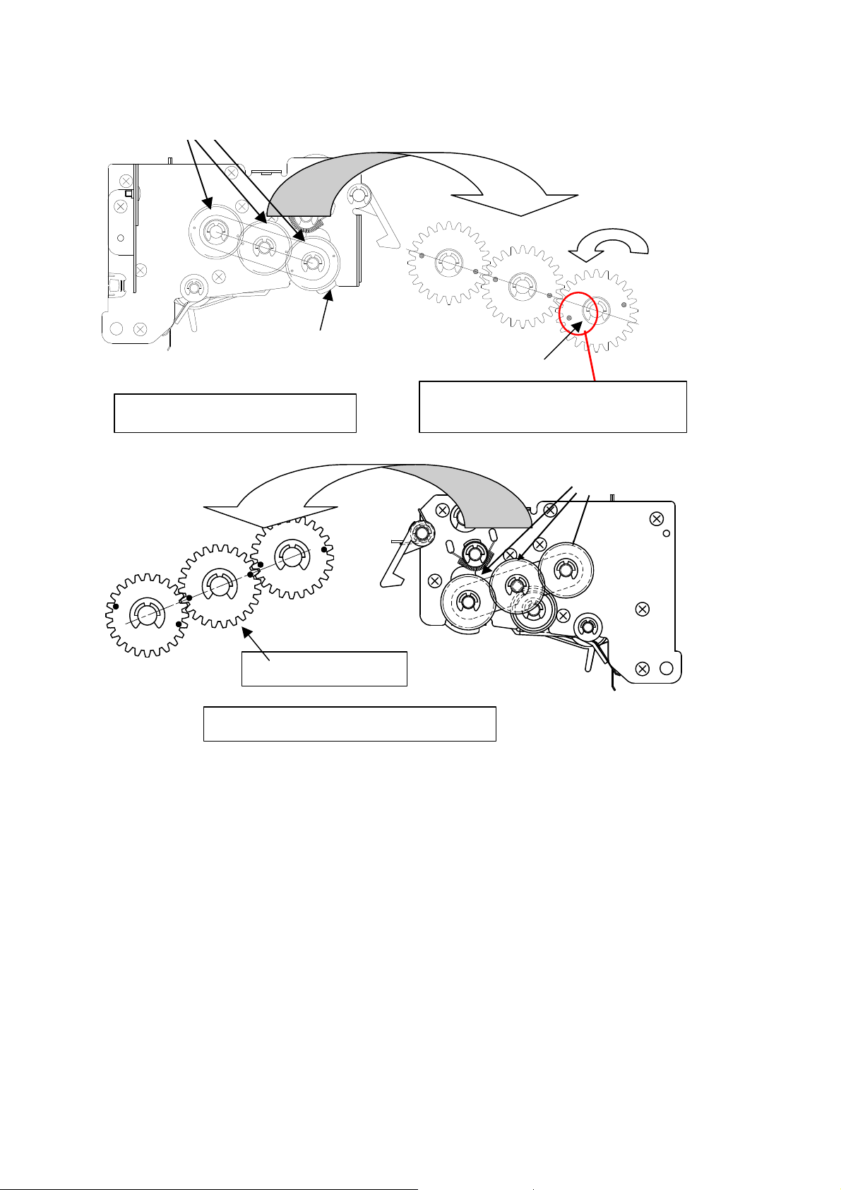
Drive gear
BSI No. F99K844 Page 2
Holding gate
Front side driving gears
Adjusting gear
Rear side driving gears (addition)
Dowel
Note: Wrong illustration in Manual
Driving gear
Note (addition)
Adjust the front/rear side with the central gear.l
The spring clutch may lock when the gear is operated. So, turn the convex portion of the l
clutch unit to push the gear.
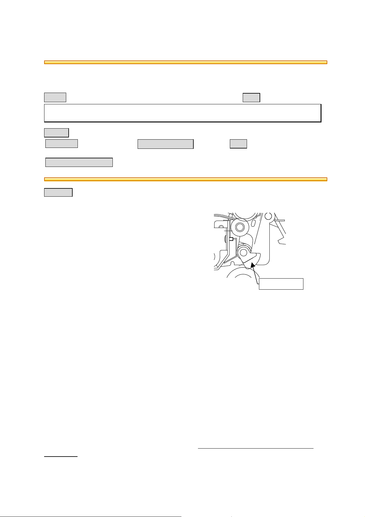
(2) Next, align the projection on the clutch unit of the holding gate, and fasten with an E-ring.
Page 3

Projection (convex portion) of clutch unit
A
Note (Addition)
When it is fixed by an E-ring, be sure to
check that the holding gate position is as in
the illustration on the right. (correct position
of holding gate)
BSI No. F99K844 Page 3
E-ring
Clutch gate
Holding gate
(3) Check driving gear installation
Make sure that it is installed correctly according to the following points. If it not installed
correctly, perform the (1)~(2) item points.
* Open the clutch unit.
(solenoid not pulled out)
* Turn the gear in the figure in the direction "A" till the holding gate is stopped.
* When the holding gate is stopped, check that B face and C face are roughly parallel.
B face: flat face of holding gate
C face: end face of frame
A
Clutch unit
B
C
 Loading...