

Page 1
BSI(Service Note) TOSHIBA
E_CH-6.pdf
TOSHIBA TEC CORPORATION
2-4-1, Shibakoen, Minato-ku, TOKYO, 105-8524 JAPAN
BSI No
F99I776
SUBJECT
Countermeasure to No Stapling
MODEL
CATEGORY
Treatment in the field
--------
CONTENT
[Phenomenon]
Paper may exit without being stapled though in the staple mode.
[Cause]
After the sheet is stapled on the stapling tray in the staple mode (the front and back of the stacked
sheets are aligned at the alignment plate on the rear side of the staple tray), stapling is performed and
the stacked sheets exit. If the alignment plate is over-aligned, the sheet becomes warped (the rising of
the center area), and the paper detection sensor on the staple tray goes OFF. It is then judged that t
here is no paper, and so stapling is not operated.
MJ1006, MJ1007
FIELD APPLICATION
To be applied when necessary
FACTORY APPLICATION
Date
UNIT
Finisher
99/09/22
----
[Countermeasure]
If the above occurs, carry out A-2 "Adjusting the Alignment Position" listed the following file, to adjust
the aligning quantity of the alignment plate suitably.
The sending file is the same as the file for BSI "F99E618". The shaded points were shown for the
changed contents of "F99E618" and are not related to this BSI.
[Sending file]
Page 2
I. ADJUSTMENTS
A. Electrical System (finisher
unit)
CHAPTER 6 TROUBLESHOOTING
1. Adjusting the Height Sensor (PS1)
Perform the following adjustments whenever you have replaced the finisher controller
PCB or the height sensor (PS1).
1) Set SW3 on the finisher controller as indi-
cated.
Figure 6-101
2) Put blank plain paper (A4 or LT) on all
trays.
3) Press SW2 on the finisher controller PCB.
A press causes the finisher to execute au-
tomatic adjustment, in which the tray unit
will shift tray 1 and then tray 2 in sequence.
• At the end of adjustment, trays will return
to home position.
• During adjustment, LED 1 flashes. At the
end of adjustment, LED1 turns and remains on.
• If automatic adjustment fails, the mechanism stops while the tray in question is
being adjusted. (At the same time, LED1
turns off.)
4) Shift all bits on SW3 to OFF*, and turn
off the copier once.
Figure 6-102
3) If you are using A4 paper, press SW2 on
the finisher controller PCB. If you are using L T paper , on the other hand, press SW1
on the finisher controller PCB.
• A press on SW2/1 will open the swing
guide and cause the alignment plate to
move to A4/LT position.
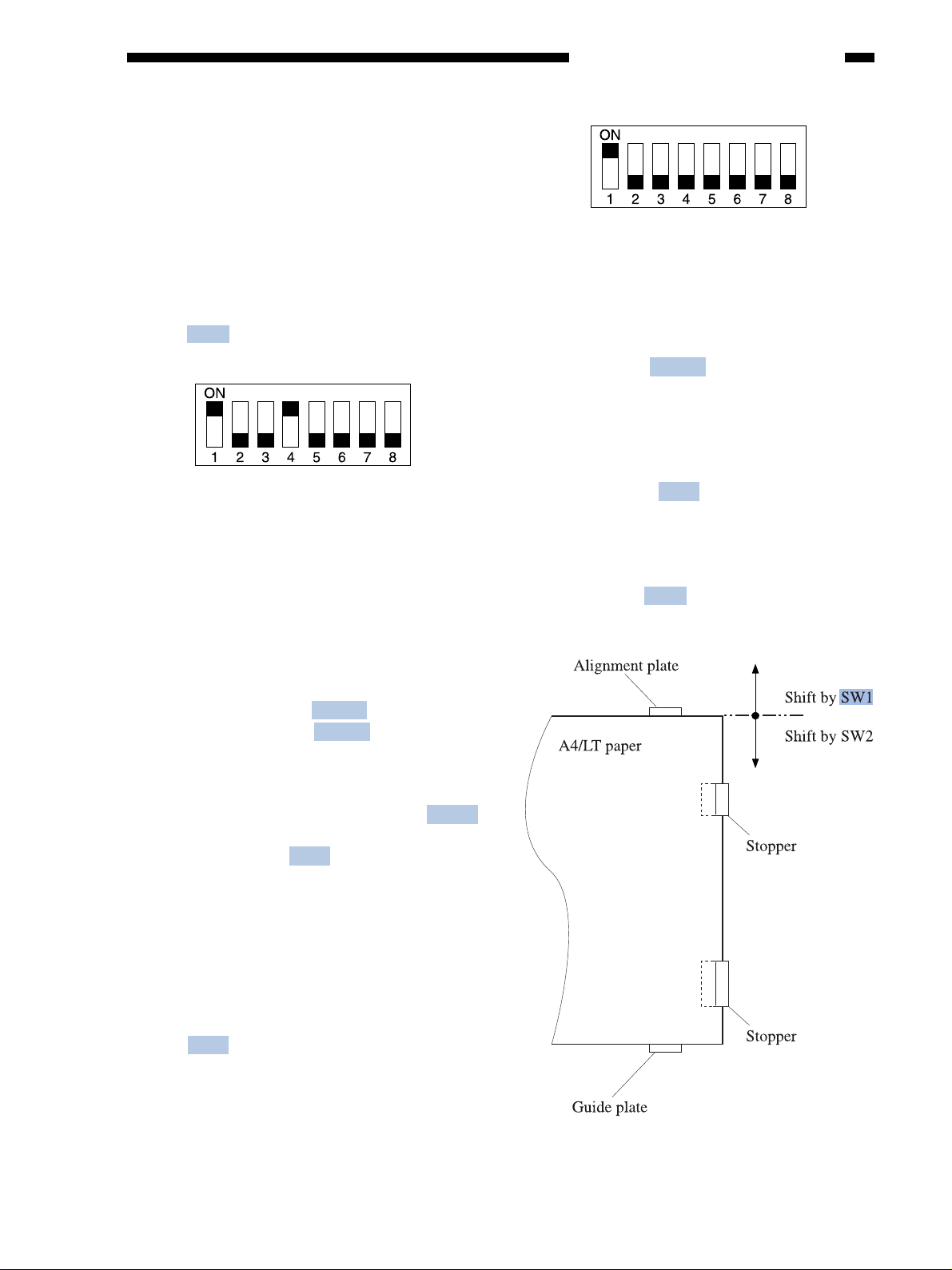
4) Place 10 sheets of A4/LT paper between
the alignment plate and the guide plate,
butting them against the stoppers.
5) Press SW2 or SW1 on the finisher controller PCB, and butt the alignment plate
against the sheets.
• A press on SW2 will shift the alignment
plate to the front in increments of 0.35 mm.
• A press on SW1 will shift the alignment
plate to the rear in increments of 0.35 mm.
2. Adjusting the Alignment Position
If you have replaced the finisher controller PCB or if an alignment fault occurs, make
the adjustments that follow. Performing the
steps will affect all paper sizes.
1) Remove the rear cov er of the finisher unit.
2) Set SW3 of the finisher controller PCB as
indicated.
Figure 6-103
6-1
Page 3

CHAPTER 6 TROUBLESHOO TING
6) Press SW2 and SW1 simultaneously to
store the adjustment value. (This will lo wer
the swinging guide.)
7) Shift all bits of SW3 to OFF*, and install
the rear cover of the finisher unit.
3. Adjusting the Stapling Position
(stapler movement range)
Make the adjustments that follow if you
have replaced the f inisher controller. Performing the steps will affect all paper sizes and all
stapling positions.
1) Remove the rear cover from the finisher
unit.
2) Set SW3 on the finisher controller PCB as
indicated.
Figure 6-104
3) If you are using A4 paper, press SW2 on
the finisher controller PCB. If you are using LT paper, press SW1 on the finisher
controller PCB.
• A press on SW2/1 will open the swing
guide and cause the feed belt to rotate.
4) Within 5 sec after pressing the switch, place
two sheets of A4/LT paper between the
alignment plate and the guide plate, butting it against the stoppers.
• When the finisher detects the paper , it will
lower the swing guide and execute stapling
(rear, 1-point). Take out the stapled paper
manually, however; deli very operation will
not be executed.
Figure 6-105
5) If the stapling position is correct, shift all
bits on SW3 to OFF* to end the adjustments. If you need to change the stapling
position, on the other hand, go to the next
step.
6) To suit the position of the staple on the
paper, press SW2 or SW1 on the finisher
controller PCB as many times as necessary .
• A press on SW2 will shift the stapling position to the front in increments of 0.3 mm.
• A press on SW1 will shift the stapling position to the rear in increments of 0.3 mm.
6-2
Page 4

Figure 6-106
7) Press SW2 and SW1 simultaneously.
• The press will open the swing guide, and
cause the feed belt to rotate. Placement of
two sheets of A4/LT paper will cause the
finisher to start stapling operation.
8) Check the stapling position. If good, shift
all bits of SW3 to OFF*. If readjustments
are necessary, go back to step 6).
CHAPTER 6 TROUBLESHOOTING
Tray shift time
Within a specific period of time:
LED 1 lights (normal).
When more than a specific period of
time:
LED 1 goes out (abnormal).
3) Likewise, when push-switch 1 is pressed,
the tray is lowered by one step. Note, however , that tray mo vement is canceled when
the current position is the lowest.
5. Delivery feeding speed check
Make sure that the deliv ery feeding speed
is 650 mm/sec or more with the delivery feeding motor fully ON.
Make sure that the deliver y feeding motor
can perform its required functions at all times.
1) Set the DIP switch settings on the Finisher
controller board as follows:
Note:
The settings held by the finisher controller
are changed as soon as SW2 or SW1 is
pressed. As such, to recover the previous
settings after the press, you must press the
other of the two switches as many times as
you pressed previously.
4. Tray shift time check
Make sure that the tray shift time is within
a specific period of time (under a load of 1500
sheets of A4 size paper of equivalent).
1) Set the DIP switch settings on the Finisher
controller board as follows:
Figure 6-107
Figure 6-108
2) When push-switch D is pressed, the delivery feeding motor operates, the number of
pulses from the encoder fed by the delivery feed motor is calculated, and LED 1
lights or goes out according to the following conditions:
Delivery feeding speed
When 650 mm/sec or less:
LED 1 lights (normal).
When less than 650 mm/sec:
LED 1 goes out (abnormal).
3) When push-switch 1 is pressed, checking
of the ability of the delivery feeding motor
to perform its functions is carried out.
2) When push-switch 2 is pressed, the time
required for tray shifting is calculated, and
LED 1 lights or goes out according to the
following conditions. Note, however, that
tray movement is canceled when the current position is the 2nd bin.
6-3
Page 5

CHAPTER 6 TROUBLESHOO TING
6. Aging mode
This mode is for simulated running of the
MJ-1006/1007.
Figure 6-109
1) To start the aging, press push-switch 2.
2) The bin is lowered to the lowermost position (home position).
3) From here on, the operation in each of the
operation modes is repeated. (To stop aging, press push-switch 2.)
7. Feed motor 1 operation check
This mode is for operating feed motor 1.
10. Switching of stacking capacity in
staple sort limit
Change of the stacking capacity in staple
sorting from 30 to 50 copies.
1) The stacking capacity in staple sorting is
increased to 50 copies by changing the DIP
switch settings on the Finisher controller
board.
Figure 6-111
Figure 6-110
1) T o start the operation of feed motor 1, press
push-switch 2.
2) T o stop the operation of feed motor 1, press
push-switch 1 again.
The operation is controlled cyclically at the
following speeds at each press of push-switch
2.
(1) 100 mm/sec → (2) 350 mm/sec →
(3) 650 mm/sec → (1) and so forth
8. Tray shift up check
The tray is raised. (Set all DIP switch set-
tings to OFF.)
1) To raise the trays, press push-switch 2.
2) Tray shifting is canceled when push-switch
2 at the tray 2 position.
9. Tray shift down check
The tray is lowered. (Set all DIP switch
settings to OFF.)
1) To lower the trays, press push-switch 1.
2) Tray shifting is canceled when push-switch
1 at the tray 1 position.
6-4
Figure 6-112
Note:
When the stacking capacity in staple sorting
exceeds 30 copies, stacking defects may
occur.
B. Electrical System (saddle
stitcher unit)
1. Adjusting the Folding Position
The folding position is adjusted by changing the settings of bits 6 through 8 of DIPSW1
on the saddle stitcher controller PCB so as to
match with the stitching position (i.e., adjusting the distance over which the paper positioning plate is moved to the folding position from
the stitching position).
If you have replaced the saddle stitcher
controller PCB, be sure to set the new DIPSW1
so the settings will be the same as those on the
old DIPSW1. If, for any reason, you must
change the folding position, perform the following steps:
Page 6

CHAPTER 6 TROUBLESHOOTING
C. Variable Resistors (VR), Light-Emitting Diodes (LED), and
Check Pins by PCB
Of the VRs, LEDs, and check pins used in the machine, those needed in the field are discussed
herein.
Note:
The VRs and check pins not discussed herein are for f actory use only . Making adjustments and checks
using these will require special tools and instruments and adjustments must be to high accuracy. Do
not touch them in the field.
1. Finisher Controller PCB
Figure 6-211
Table 6-211
6-21
 Loading...