

Page 1
BSI(Service Note) TOSHIBA
TOSHIBA TEC CORPORATION
2-4-1, Shibakoen, Minato-ku, TOKYO, 105-8524 JAPAN
BSI No
F99I769
SUBJECT
Service Parts for Countermeasure to Prevent Pitch Line Problems
MODEL
CATEGORY
Other countermeasures
----------
CONTENT
In a machine used for a long time, there is a possibility that pitch line problems may occur. To prevent
this, parts with improved rigidity and coupling have been newly appointed as service parts for market
installation. Be sure to install them according to the "Instructions for setup".
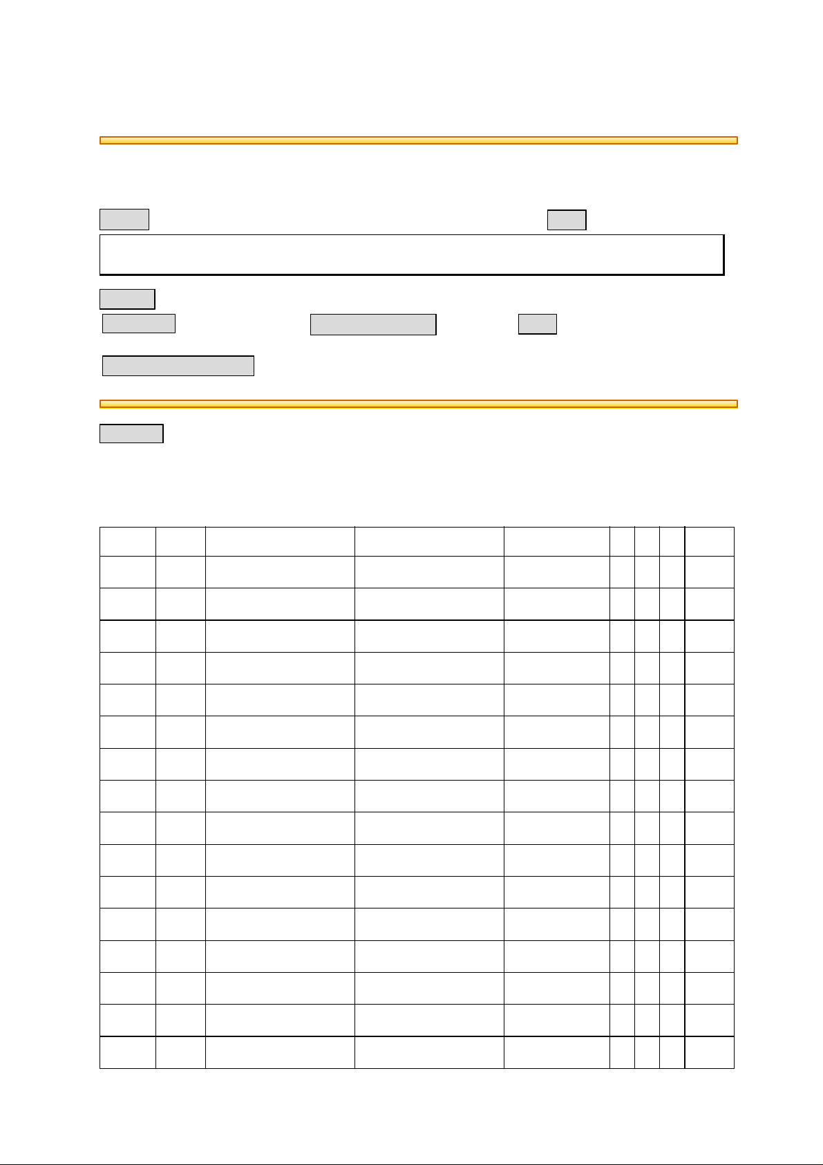
[Changed/Added Part No.]
Refer to
No.
FC70
FIELD APPLICATION
To be applied when necessary
FACTORY APPLICATION
P-I Before Change After Change Note P I R FAA
01 101-1 ---------- 4401922370
SHAFT
02 101-2 ---------- 4401922380
PLATE
03 101-3 ---------- 4401922390
GEAR100T
04 101-4 ---------- 4401922400
BUSHING
05 101-5 ---------- 4402417600
C-RING
06 101-6 ---------- 4401922410
BUSHING
07 101-7 ---------- 4401922420
COLLAR
08 101-8 ---------- 4401922430
PRESSURE SPRING
09 101-9 ---------- 4401922440
PLATE
10 101-10 ---------- 4401922450
HOLDER
11 101-11 ---------- 4401922460
FLYWHEEL ASSY
12 101-12 ---------- 4401922470
PRESSURE SPRING
13 101-13 ---------- 4402405810
HOLDER
14 101-14 ---------- 4402423670
SCREW
15 101-15 ---------- 4401922480
SCREW
16 101-16 ---------- 4402424030
SPRING WASHER
---- A - D -
---- A - D -
---- A - D -
---- A - D -
---- A - D -
---- A - D -
---- A - D -
---- A - D -
---- A - D -
---- A - D -
---- A - D -
---- A - D -
---- A - D -
---- A - D -
---- A - D -
---- A - D -
UNIT
Other
Date
99/10/04
1144-016-089
Page 2
BSI No. F99I769 Page 2
P-I: Page-Item P: Contents of Change I: Interchangeability R: Reasons for Change
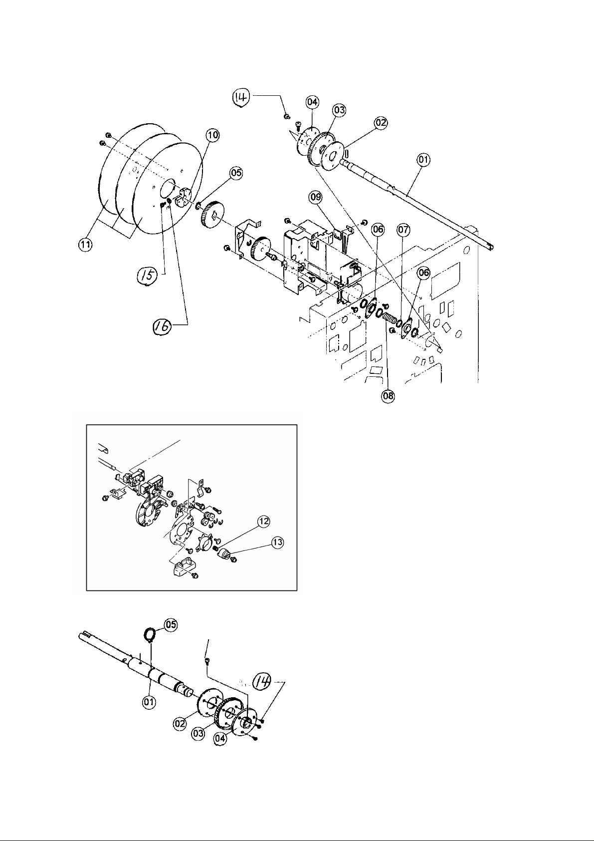
[Instructions for setup]
Stepped screw
Page 3

BSI No. F99I769 Page 3
After setting the plate (02), the gear (03) and the bushing (04) to the PC shaft (01), and screwing 1.
them with 3 screws (14), fix the step screw (Service Parts List Page 8 Item No.36 "4402406000").
Install the C-ring (05) to the PC shaft (01).2.
PC front frame
Installation screw
After inserting the PC shaft (01) to the bushing of the copier, temporarily fix the PC front frame.3.
Install the bushing (06), collar (07), the pressure spring (08) and C-ring (05).4.
PC rear frame
Earth plate
Remove the earth plate from the PC rear frame.5.
Fix with the plate (09) and the earth plate.6.
(Note) When there is insufficient grease, apply some grease. ("Conductive grease" can be used if
it is available locally.)
Replace the bushing (06).7.
PC rear frame
Temporarily fix the PC rear frame.8.
Tighten completely while pushing the PC rear frame in a straight direction.9.
Install the C-ring (05).10.
Page 4

BSI No. F99I769 Page 4
The C-ring must be slightly lower than center.
NO GOOD
Remove the PC front frame and reinstall.11.
(Note) Then, check that the PC front can be installed smoothly without any contact against the PC
shaft.
<When the frame cannot be installed smoothly>
1. Remove the bushing and check the position of the PC shaft (01).
2. When the PC shaft (01) is not fix at its correct home position, remove the PC rear frame and
start again from "8".
Parallel pin
PC outside gear
C-ring
Setting the parallel pin of the copier, install the PC outside gear and fix it with the C-ring. 12.
The installation holder of the fly wheel (10) is attached while pressing, and is fixed to the PC shaft 13.
with a bolt (15) and a washer (16).
C-ring
Page 5

PC outside gear
After the PC outside gear and the PC driving gear have been cleaned, apply sufficient grease. 14.
BSI No. F99I769 Page 5
PC driving gear
Install the fly wheel assembly (11) by means of 3 screws (14).15.
(Note) Check whether there is any rattling. If there is any, reinstall then.
PC unit
PC front frame
Charger unit assembly
Remove the PC front frame and install the PC unit.16.
Install the pressure spring (12) and the holder (13).17.
Reinstall all the removed parts.18.
 Loading...