

Page 1
BSI(Service Note) TOSHIBA
TOSHIBA TEC CORPORATION
2-4-1, Shibakoen, Minato-ku, TOKYO, 105-8524 JAPAN
BSI No
F99E610
SUBJECT
Addition of Attaching Position (Automatic Original Feeder: ADF)
MODEL
CATEGORY
Correction of Service Manual
-
CONTENT
The attaching position connected with the following parts has been added.
Gasket (transfer belt unit) P.84-I.26 Countermeasure to electromagnetic waves
Discharge brush (paper feed area) P.81-I.59 Prevention of static electricity occurring during
Shield mylar (DF cover) P.85-I.40 Preventing connect with PC board and cover
Pad cushion P.81-I.60 Keeping the original-separation performance
Reverse area entrance mylar P.83-I.37 & 38 Preventing inserting into the gap between the
Reverse area side mylar P.83-I.39 & 40 Preventing the corners folding in Letter size
DP5570, DP6570
FIELD APPLICATION
Others
FACTORY APPLICATION
Part Name Parts List (P-1) Content
paper feeding
belt and the reverse guide
reverse operation
UNIT
ADF
Date
99/05/17
-
Service Manual
16. Automatic Document Feeder (ADF)
16. 12 Disassembly and Replacement
[V] Mylar sheet, etc.
[Addition]
Page 2
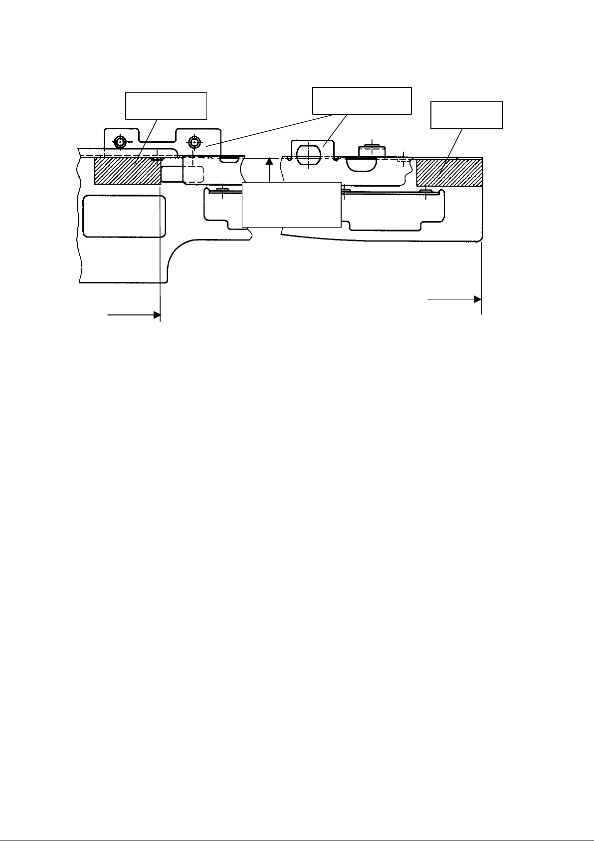
17. Gasket (transfer belt unit)
BSI No. F99E610 Page 2
Gasket
Window
FRAME-BELT-F
Aligning
Gap: 0 ~ 1mm
-0 ~ 1mm
Must not protrude
beyond the window
Must not protrude beyond
the edge of the frame
18. Discharge (Paper feeder area)
[Attaching Position]
Attach it to the two edge positions in GUIDE-ALGN-IN (A and B below).
Gasket
-0 ~ 1mm
Note 1. Insert the discharge brush between the FRM-FEED-794 and the GUIDE-ALGN-IN (rear side
only).
Note 2. To perform correctly Note 1, be sure to make the discharge brush rise up from the
GUIDE-ALGN-IN.
(Refer below.)
Page 3
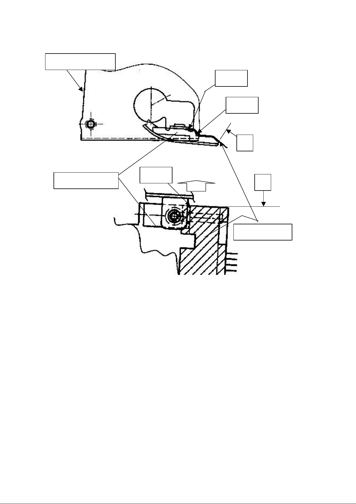
FRM-FEED-794-R
BSI No. F99E610 Page 3
Note 1
Note 2
A
GUIDE-ALGN-IN
Note 2
Rear side
B
Discharge brush
Page 4
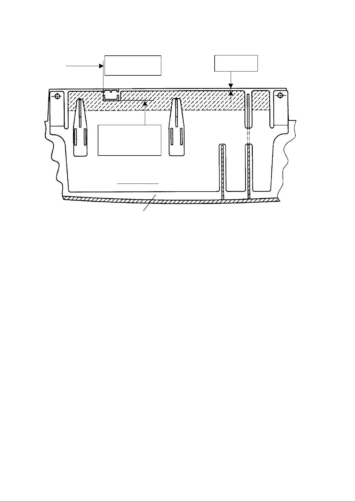
19. Shield mylar (DF cover)
BSI No. F99E610 Page 4
0 ~ 1mm
20. Pad cushion
Aligning with rib
0 ~ 1mm
Aligning with rib
Shield mylar
COV-DF-794
(2.4 ~ 2.5)
Page 5

Pad cushion
BKT-PAD-SPT-794
Pad cushion
BSI No. F99E610 Page 5
0~1mm
Must not protrude beyond the bracket
21. Reverse section entrance mylar
0~1mm
Must not protrude beyond the bracket
Align and then attach
(Gap = 0~0.5mm)
Page 6

Unit: mm
BSI No. F99E610 Page 6
SHEET-RVS-M
BELT
22. Reverse section side mylar
1
0 ~ 1
+0.5
-0.5
0 ~ 1
0 ~ 0.5
MYLAR-RVS-M
SHEET-RVS-M
MYLAR-RVS-M
Not to protrude
Page 7

0~`0.5
Not to become stuck on the rib
MYLAR-RVS-U-R
MYLAR-RVS-U-F
0~`0.5
Not to become stuck on the rib
BSI No. F99E610 Page 7
Rounded corner end
+1
0
-1
View
Unit: mm
 Loading...