

Page 1
BSI(Service Note) TOSHIBA
TOSHIBA TEC CORPORATION
2-4-1, Shibakoen, Minato-ku, TOKYO, 105-8524 JAPAN
BSI No
F99D591
SUBJECT
Correction to Service Handbook
MODEL
CATEGORY
Correction of Service Manual
-
CONTENT
Errors and omissions in the explanation have been found in the Service Handbook. This BSI is to
provide the necessary correction.
DP5570, DP6570
FIELD APPLICATION
Others
FACTORY APPLICATION
1. Adjustment
1.1 Error Codes
[Changes]
Main Points
* Elimination (EAD) and Addition (C46,E12) of error code
* Addition of reference items
* Alteration of Group
* Supplement and correction of content
The changed error codes list is attached as follows.
UNIT
Other
Date
99/04/27
-
error code.pdf
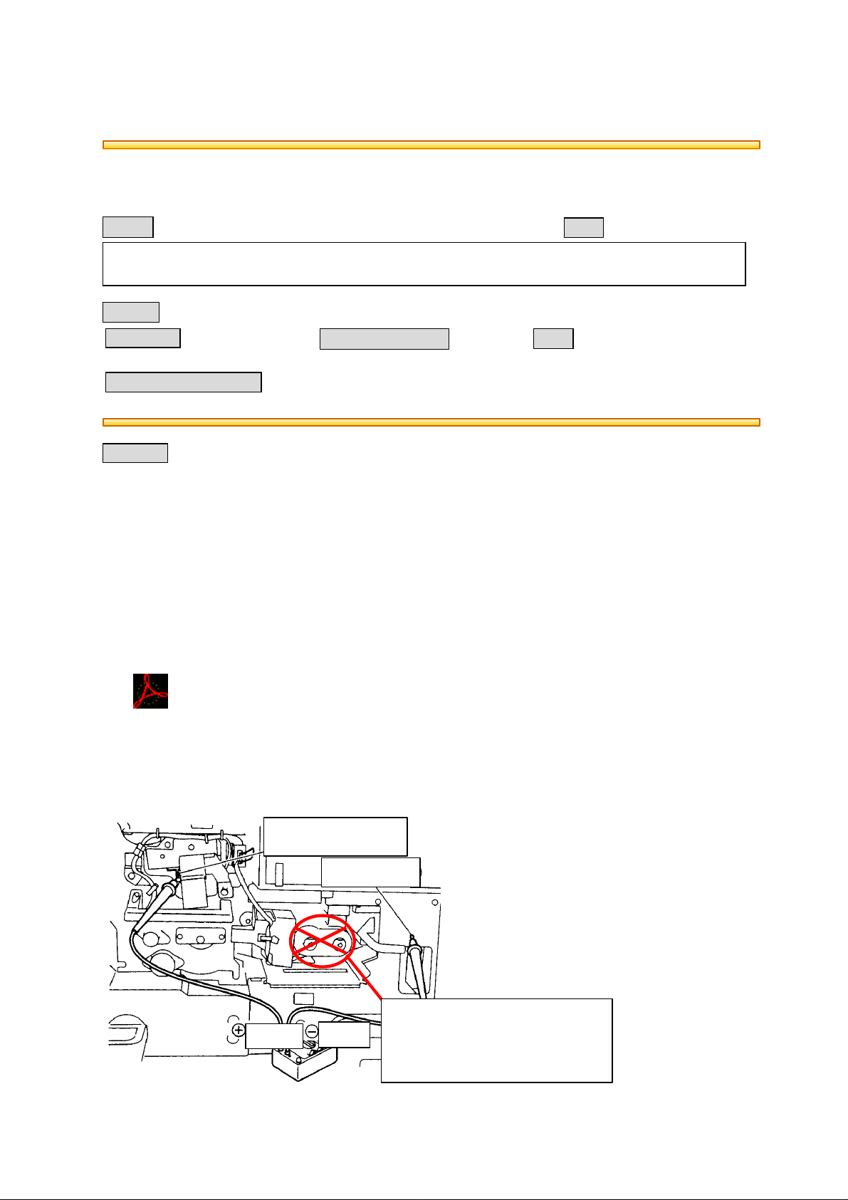
1.10.1 Adjustment
(1) Preparation for Measurement
1. Charging
[Error]
Main charger rail
Terminal
Frame (ground
Remove the developer unit as
Terminal
described in the explanation.
(Illustration error)
)
Page 2

1.2.4 Adjustment Mode ("05")
[Error]
Code Name Mode Default Value Allowance
Value
335-0 Acceleration curve setting
(50~59%)
452-0 PFP middle cassette aligning
amount
(upper unit RGT section)
330mm~
456-0 PFP lower cassette aligning
amount (upper unit RGT
section) 330mm~
580 Automatic gamma
adjustment for error diffusion
[Error]
Error Item Corrected Content Available Code
Mode (Standard)
(Text/Photo)
Adjustment HPF strength setting
HPF strength setting in same reproduction
scale
ALL
ALL
ALL
PPC -
1
2
5
2
5
2
503,505,508,514,593,620,
620
0~2
0~31
0~31
BSI No. F99D591 Page 2
Operation
Procedure
Group
6
7
5
1.2.5 Setting Mode ("08")
[Error] [Error list]
Error Item Corrected Content Available
Code
Image Mode Photo/Text
Text/Photo
Remarks Standard
Text/Photo
503 Errors have been found in the list after
"1.6 item"
Photo/Text (error) ->
Text/Photo (correct)
550
1.5.2 Adjusting the printer section
(e) Image distortion adjustment
(3) Coat with screw locking agent after the image skew adjustment.
[Addition]
Screw locking agent
* 4406361350 BOND-1401E
* At the time purchase each can contains 1kg which is
quite a lot to carry around with you, so you should divide
up the amount into smaller containers.
Note
1.24 Fine Adjustment of Binding Position/Folding Position
[Addition]
By moving the paper positioning plate up or down, fine adjustment of the binding position/folding
position can be made.
Page 3

BSI No. F99D591 Page 3
Adjustment Code "05" - Code "468-0~2"
* Increasing the adjustment value shifts the binding position/folding position towards the right-hand
page by 0.25mm for each/step.
* Decreasing the adjustment value shifts the binding position/folding position towards the left-hand
page by 0.25mm for each/step.
Adjustment value=0 Adjustment value (+) Adjustment value (-)
Right-hand
page
Left-hand
page
Note
* When fine adjustment of the binding position/folding position is performed, the following result
should be obtained.
* When a book is made, to have it opening from the right: page 1 (see figure A below).
A A
Adjustment value (+) Adjustment value (-)
1.25 Adjustment of RADF Height
[Addition]
The adjustment screws attached to the hinge are to adjust the height of the gap between the glass
and the RADF.
(1) Adjustment screws:
If they are turned counterclockwise, the gap becomes narrower.
The adjustment screws are on the right hinge and the left hinge (2 places).
(2) The gap (arrow A) of the adjustment value is 0 ~ 0.5mm.
Page 4

BSI No. F99D591 Page 4
Adjustment screw
A A
DF spacer DF spacer
1.26 Flapper Solenoid Adjustment
[Addition]
(1) Push the flapper solenoid plunger by hand.
(This makes the solenoid able to be pulled in electrically.)
(2) Install BRKT-SOL-RVS so that it contacts with the flapper rubber and the flapper lever.
(3) Fix BRKT-SOL-RVS with the screw.
(4) With the solenoid pulled out, confirm that there is no gap between the flapper rubber and the
flapper lever.
Flapper lever
Plunger
Flapper rubber
Original glass
Screw
2. Periodical Maintenance
2.3 Periodic Inspection Check List
[Addition]
BRKT-SOL-RVS
Page 5

BSI No. F99D591 Page 5
Category Item to check Cleaning at
400,000
copies
(340,000
copies)
Scanner 21-1 Shading glass O <P.44-I.7>
Lubrication at
400,000
copies
(340,000
copies)
Replace
X 1,000
Check
while
on
Remarks
<Page-Item>
21-1
4. Troubleshooting
4.2 Process Line Service Calls
[Addition]
[C42] Drum thermistor disconnection
(1) Check the Drum thermistor connector (the relay connector is attached to the front frame of
Cleaner Unit)
* Thermistor broken?
* Is the connector disconnected?
* Is the Pin disconnected?
(2) Check the relay connector J728: the connector for the Cleaner Unit)
* Is the connector disconnected or about to become so?
* Is the pin disconnected out?
(3) Replace the LGC board
4.3 Fuser
[Addition]
[C46] Lower thermistor trouble (e.g. to do with the pressure roller) after having become ready
(1) Check the thermistor
* Are the connectors disconnected?
* Is the thermistor firmly contacting the pressure roller?
* Is the thermistor harness broken?
(2) Checking of the LGC board is the same as with [C41].
(3) Reset the status counter
* When [C46] occurs, reset the status counter 3 to 0 by the same procedure as for error [41].
4.4 Communication System Service Calls
[Addition]
[F07] SYS board-LGC board communication trouble
[F11] SYS board-SLG board communication trouble
(1) Check the connectors J102 and J108 on the SYS board for disconnection.
(2) Check the connector J330 on the LGC for disconnection.
(3) Check the connector J2 on the SLG board for disconnection.
(4) Check the harness between the SYS and the SLG for breaks and disconnected pins.
(5) Check the harness between the SYS and the LGC for breaks and disconnected pins.
(6) Check the FROM version on the SYS board.
Page 6

BSI No. F99D591 Page 6
(7) Check the MROM (IC36) version on the LGC board.
(8) Check the SROM version on the SLG board.
(9) Replace the SYS board.
(10) Replace the SLG board.
(11) Replace the LGC board.
4.5 ADF System Service Calls
[Addition]
[C76] Transmission time-out error
[C77] Transmission buffer full
[C78] ADF power ON I/F error
[C79] Reception time-out error
(1) Check the harness between the ADF control PC board and the scanner control PC board for
disconnections or breaks.
(2) Check mainly the IC2,IC3,IC14,CN1 on the ADF control PC board for breaks and short-circuits.
(3) Check mainly the IC1,IC7,J8 on the scanner control PC board for disconnections and
short-circuits.
(4) Replace the ADF control PC board.
(5) Replace the scanner control PC board (SLG board).
[C93] ADF original stop signal not received
(1) Check the harness between the ADF control PC board and the scanner control PC board for
disconnections and breaks.
(2) Check mainly the IC2,IC3,IC14,CN1 on the ADF control PC board for disconnections and
short-circuits.
(3) Check mainly the IC1,IC7, J8 on the scanner control PC board for disconnections and
short-circuits.
(4) Check whether the ADF aligning sensor and the ADF timing sensor are detecting normally or not.
(5) Replace the ADF control PC board.
(6) Replace the scanner control PC board.
4.7 Others Trouble Service Calls
[Addition]
[CD1] Brush motor lock error
(1) Check whether the fur brush has become locked mechanically.
* Are there any foreign objects?
* Are there any toner clumps in the transport section?
(2) Check whether connectors on the LGC board have become removed or the pins disconnected,
etc..
(3) Replace the brush motor.
(4) Replace the LGC board.
[CD2] Auger motor lock error
(1) Check whether the auger has become locked mechanically.
* Are there any foreign objects?
* Are there any toner clumps in the transport section?
(2) Check whether connectors on the LGC board have become removed or the pins disconnected,
etc..
(3) Replace the auger motor.
(4) Replace the LGC board.
[F10] HDD formatting malfunction
(1) Perform the "HDD formatting" (Setting Mode: 08 -> 690 -> 2).
(2) Make sure that the HDD is mounted.
(3) Make sure that a dedicated HDD is mounted.
(4) Make sure that the HDD connector pins are not bent.
Page 7

BSI No. F99D591 Page 7
(5) Check HDD connector J106 on the SYS board for disconnection.
(6) Replace the harness.
(7) Replace the HDD.
(8) Replace the SYS board.
4.9 Finisher System Service Calls
[Addition]
[CCO] Sensor connector connection error: [Procedure 1]
Is the guide home position sensor (P13S) or saddle stitcher controller board connector connected?
YES
Is there a disconnection between the sensor and the saddle stitcher?
YES
Is DC5V being supplied from J9-7 on the saddle stitcher control board?
YES
Is J9-8 of the saddle stitcher controller board correctly connected to the ground?
YES
END
[CCO] Sensor connector connection error: CCO [Procedure 2]
Is the connector of the paper pressing plate home position sensor (P14S) or the connector of the
saddle stitch controller board connected?
YES
Is the connector between the sensor and the stitcher disconnected?
YES
Is DC5V from J9-10 of the saddle stitcher controller board supplied?
NO
Connect the connector.
NO
Correct this.
NO
Replace the saddle stitcher controller board.
NO
Replace the saddle stitcher controller board.
NO
Connect the connector.
NO
Correct.
YES
Is J9-11 of the saddle stitcher controller board correctly connected to the ground?
YES
END
[CC0] Sensor connector connection error: [Procedure 3]
Is the connector of the paper pressing edge position (P15S) or the saddle stitcher controller board
connected?
YES
Is the connection between the sensor and the saddle stitcher disconnected?
YES
Is DC5V from J9-13 of the saddle stitcher controller board supplied?
YES
Is J9-4 on the saddle stitcher controller board correctly connected to the ground?
NO
Replace the saddle stitcher controller board.
NO
Replace the saddle stitcher controller board.
NO
Connect the connector.
NO
Correct.
NO
Replace the saddle stitcher controller board.
Page 8

BSI No. F99D591 Page 8
YES
END
[CC1] Microswitch malfunction: [Procedure 1]
Check the switch actuator in the entrance door. Are the switch and the sensor being moved correctly
?
YES
Check the entrance door switch. Is the switch normal?
YES
Measure the J1-8 voltage on the saddle stitcher controller board when the entrance door is open.
Is there 5V being supplied?
YES
Measure the voltage across J19-2 (+) and J19-2 (-) on the saddle stitcher controller board. Is 24 V?
YES
Check and correct the wiring between J19 and J1 of the saddle stitcher controller board and replace
the saddle stitcher controller board if the wiring is normal.
NO
Replace the saddle stitcher controller board.
NO
Correct the mechanism.
NO
Replace the switch.
NO
The sensor is broken, so replace it.
NO
Replace the saddle stitcher controller board.
[CC1] Microswitch malfunction: [Procedure 2]
Check the switch actuator of the front door. Are the switch and the sensor being moved correctly?
YES
Check the front door switch. Is the switch normal?
YES
Measure J11-12 voltage access of the saddle switcher controller with the front door open. Is 5V being
supplied?
YES
Replace the saddle stitcher controller board.
[CC1] Microswitch malfunction: [Procedure 3]
Check the switch actuator of the exit door. Are the switch and the sensor being moved correctly?
YES
Check the exit door switch. Is the switch normal?
YES
Measure J11-9 voltage access of the saddle stitcher when the exit door is open. Is it 5V ?
YES
Replace the saddle stitcher controller board.
NO
Correct the mechanism.
NO
Replace the switch.
NO
The sensor is broken, so replace it.
NO
Correct the mechanism.
NO
Replace the switch.
NO
The sensor is broken, so replace it.
[CC2] Communication error between finisher saddle
Does turning the power switch on the main unit OFF and then ON again rectify the trouble?
YES
NO
END
Page 9

BSI No. F99D591 Page 9
Is the wiring between the finisher controller board and the saddle stitcher board normal?
YES
Measure the voltage access between J3-2 (+) on the finisher controller board and J3-1 (-). Is it DC
24V?
YES
Replace the saddle stitcher controller board.
[Elimination of following two items]
4.10 Optional Attachment System Service Calls
4.11 SM Communication Trouble Service Calls
NO
Correct.
NO
Replace the finisher controller board.
Page 10

Group Error code Machine status
Transporting jam inside the
copier 1
Paper feeding jam
Transport jam from feed for
RGT
opened during copying
ADU reversal section transport
line jam
Original tr an sporting ja m at the
ADF
Paper jam at the fin ish er
E01 Fuser exit switch non-arrival jam
E02 Fuser exit switch accumulation jam
E03
E09
Paper remaining inside the copier at power ON
Jam caused by HDD error
E0A Image transport ready timeout
(Image data transport error between SYS board and PLG
board)
E12 Bypass feeding jam
E15 PFP 1st cassette feeding jam
E16 PFP 2nd cassette feeding jam
E17 PFP 3rd cassette feeding jam
E19 LCF feeding jam
PFP transport jam (non-arrival at RGT)
E31
E32
E33
E31:During upper cassette feed
E32:During middle cassette feed
E33:During lower cassette feed
PFP transport jam PFP
E34
E35
E36
E31:During upper cassette feed
E32:During middle cassette feed
E33:During lower cassette feed
E41 Copier front cover is opened during copyingPaper jam if some cov er is
E47 Exit jam processing cover is opened during copying
E51 ADU RGT non-arrival
E51 ADU transport TR1 non-arrival
E52 ADU transport TR2 non-arrival
E53 PFP upper cassette RGT non-arrival (from ADU feed)
E54 ADU feed non-arrival
E55 Paper on transport path at copy end
E56 Paper on PFP transport path after door open/close
E57 Reversal switch non-arrival jam
E58 Reversal switch accumulation jam
E59 Exit switch accumulation jam
E5A Exit switch non-arrival jam
E5B ADU transport start timeout jam
E71 Original feeding jam at the feed section of the ADF
E72 Original transporting jam at the transport section of
the ADF
E73 Original exiting jam at the exit section of the ADF
EA1 Transporting delay jam
EA2 Transporting stationary jam
EA3 Jam at power ON
EA4 Door open jam
EA5 Staple jam
EA6 Early arrival jam
Reference
Page 11

Group Error code Machine status
Paper jam at the fin ish er
Service call from the optical
system
Service call from the process
Fuser related
Service call from
communication
Service call ADF
EA8 Finisher saddle staple jam
EA9 Finisher saddle door open jam
EAA Finisher saddle power ON jam
EAB Finisher saddle transport accumulation jam
EAC Finisher saddle transport delay jam
EAE Finisher receive time-out jam
Paper cannot be detected from the copier in a fixed-time
.
EB3 Finisher ready time-out error
(Finisher cannot prepare for receiving the paper after the
leading edge of the paper reaches to RGT in a fixed-time.)
EB5Copier transport jam 2
EB6
C26 Peak detection error
C27 Home switch does not turn OFF
C28 Home switch does not turn ON
C29
C36 Charger cleaning operation error
C37 Transfer belt operation error
C42 Drum thermistor disconnection
C41 Abnormal thermistor or heater disconnection at power
Double jam
(Residence jam occurs because of the double paper is separated
in paper feeding.)
Scanner disconnection detection
4.1
4.1
4.1
4.1
4.2
4.2
4.2
4.3
ON
C43 Warming up mode after disconnection judgment, or
4.3
abnormal thermistor after ready
C44
C45
C46
Warm-up time after detected disconnection or heater
disconnection after ready
Thermistor disconnection at HTR edge portion
Lower thermistor (press roller) error after ready (Low
temperature is detected because of disconnection or conn ect or
omission.)
C56 Communication error between PFC and MCPU
C57 Communication error between MCPU and IPC
C58 Communication error between IPC and the finisher
C59 Communications error between MCPU and LCPU
F07 Communications error between SYS and LGC boards.
4.3
4.3
4.3
4.4
4.4
4.4
4.4
4.4
F11 Communications error between SYS and SLG boards 4.4
C72 Defective adjustment by the aligning sensor detected
C73 EEPROM defect i v e ini tial iza tio n
C74 Defective adjustment by the exit/reversal sensor
4.5
4.5
4.5
detected
C76 Transmission time-out error
C77 Transmission buffer full
C78 ADF power ON I/F error
C79 Reception time-out error
C80 Defective adjustment of ADF timing sensor
4.5
C93 ADF original stop signal not received
Reference
Page 12

Group Error code Machine status
Service call from the laser optical
Service call from the finisher
Service call from the others
CA1 Polygonal motor is abnormal
CA2 HSYNC is abnormal
CA3 Secondary scanning rough adjustment error
CA4 Primary scanning counter load error
CA5 Laser power adjustment error
CA6 Laser PWM calibration error
CA9 Image data transfer malfunction from SYS board
CAA Secondary scanning fine adjustment error
CAB Secondary scanning inter-page compensation error
CAC Primary scanning dot adjustment error
CAD Primary scanning tap adjustment error
CAE Primary scanning tap amount measurement error
CAF Primary scanning inter-page compensation error
CD0 Laser initialize time-out error
CB1 Transport motor is abnormal
CB2 Exit motor is abnormal
CB3 Tray elevation motor is abnormal
CB4 Alignment motor is a bn or mal
CB5 Staple motor is abnorma l
CB6 Staple unit shift motor is abnormal
CB7 Stacking sensor is abnormal
CB8 Backup RAM data is abnormal
CB9 Saddle thrust motor is abnormal
CBA Saddle front staple motor is abnormal
CBB Saddle inner staple motor is abnormal
CBC Saddle align men t mo to r is abn or ma l
CBD Saddle guide motor is abnormal
CBE Saddle fold motor is abnormal
CBF Saddle positioning plate motor is abnormal
CC0 Sensor connector connection error
CC1 Microswitch error
CC2 Communications error between finisher saddle
C92 Power abnormality interrupt error
C94 MCPU is abnormal
C99 PFC microcomputer is abnormal
CD1 Brush motor lock error
CD2 Auger motor lock error
F10 HDD formatting error
Reference
4.8
4.8
4.8
4.8
4.8
4.8
4.8
4.8
4.8
4.8
4.8
4.8
4.8
4.8
4.9
4.9
4.9
4.9
4.9
4.9
4.9
4.9
4.9
4.9
4.9
4.9
4.9
4.9
4.9
4.7
4.7
4.7
4.7
4.7
4.7
 Loading...