

Page 1
BSI(Service Note) TOSHIBA
TOSHIBA TEC CORPORATION
2-4-1, Shibakoen, Minato-ku, TOKYO, 105-8524 JAPAN
BSI No
F98L473
SUBJECT
New Model DP-2570 (Service Manual)
MODEL
CATEGORY
New Model Description
----------
CONTENT
We are pleased to announce the availability of our newes t copier, the DP-2570. The DP-2570 is very
similar to the DP-2460, expect for minor changes. No Service Manual has been specially prepared
for the DP-2570 and this BSI, in which the differences from the DP-2460 are shown, is to serve as a
substitute.
DP2570
FIELD APPLICATION
Others
FACTORY APPLICATION
UNIT
Other
Date
99/01/06
----
The changed points in the DP-2460 Service Manual have been sent by PDF file. Changed points are
shown shaded, however, pay attention to the following points.
l
Refer to "DP-2570 Unpacking/Setup instructions" in the Unpacking/Setup instructions of th e
copier (DP-2460 Service Manual 21.1).
l
The files name is shown as pages for the Service Manual .
#e21-45.pdf #e02-5_10_11_12_16.pdf#e09-1_2_3.pdf#e16-75.pdf #e21-25.pdf
#e21-28.pdf #e01-4.pdf
Page 2
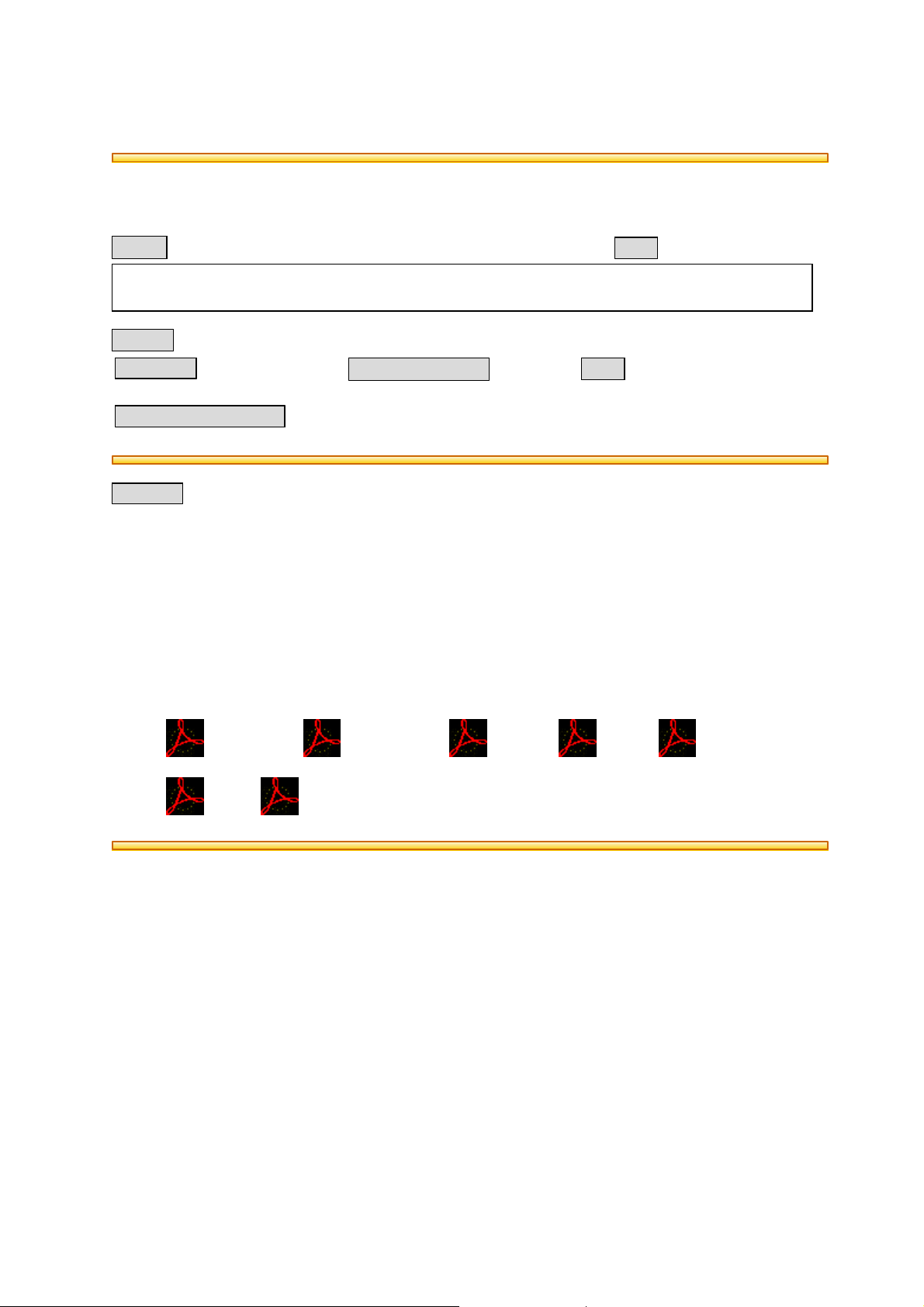
21.12 Key Copy Counter MU-8/MU-10
To install the key copy counter, the following parts are required:
• MU-10 Counter socket
• MU-8 Key copy counter
Counter socket
• MU-10
Key copy counter
• MU-8
(1) Remove the right top cover (feed side).
Cut the window for the counter.
(2) Pull out the harness connector from the open-
ing in the machine frame.
(3) Cut the short harness of the connector.
Protect the ends of the cut harness not to
make a short circuit with the machine frame
etc.
Note: Remove the rear cover if the harness con-
nector is in the back etc.
Screw holes for the socket
Harness
connector
December 1998 © TOSHIBA 21 - 45 2470 UNPACKING INSTRUCTIONS
Page 3
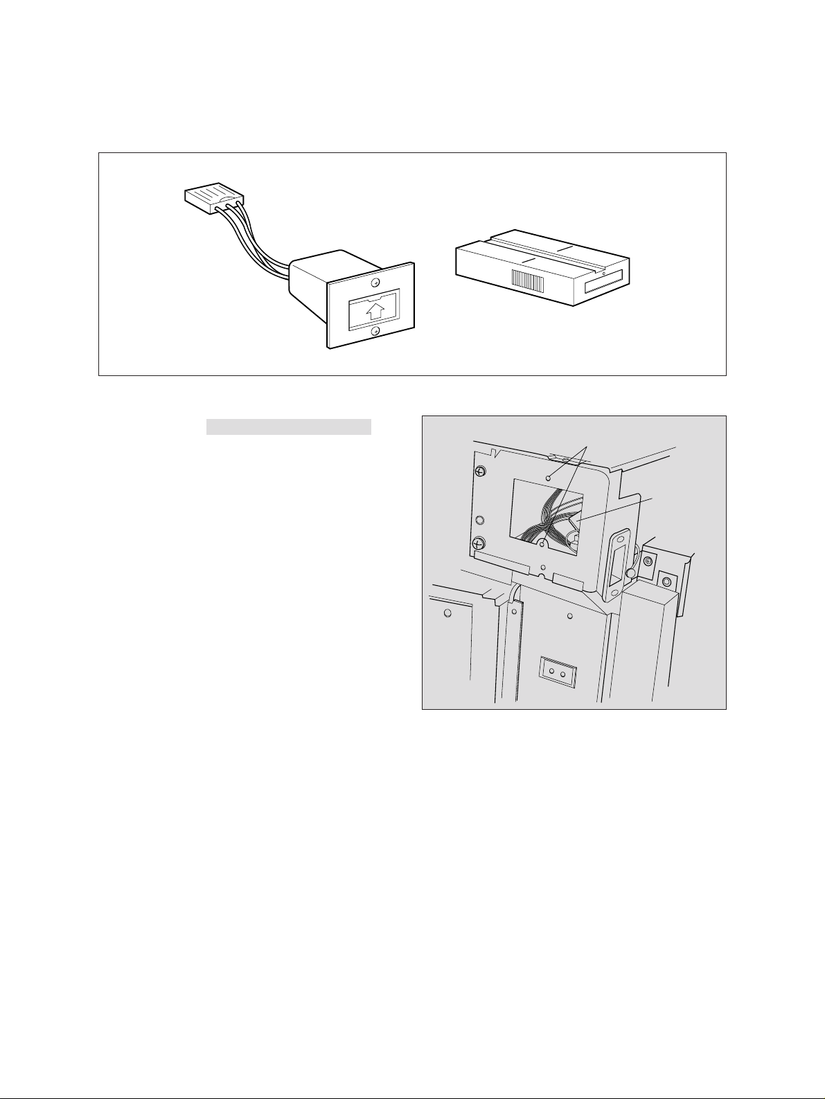
[B] PC boards
[Front side]
52
40
41
44
37
46
34
33
35
36
42
45
43
49
51
47
38
48
39
No. Name
CM Key PC board (PWA-F-KEY-230)
CN Display PC board (PWA-F-DSP-230)
CO
Liquid crystal display PC board (K-LCD-TOUCH-230)
CP Panel PC board (PWA-F-PNL-230)
CQ Control panel PC board (PWA-F-CNT-230)
CR High-voltage power supply (PS-HVT-220)
CS Logic PC board (PWA-F-LGC-220)
DT Image process PC board (PWA-F-IMG-220)
DK Discharge LED PC board (LP-ERS)
DL CCD PC board (PWA-F-CCD-220)
*2: Option
[Rear side]
No. Name
DM
DN
Scanning motor drive PC board (PWA-F-SDV-220)
Manual size detection PC board (PWA-F-SFB-220)
DO*2 Hard disk drive (HDD)
DP System PC board (PWA-F-SYS-222)
DQ Page memory PC board (PWA-F-PMB-777)
DR*2 PM extension memory (KR-3007)
PRT PC board (PWA-F-LANPRT-799+PWA-F-EXT-799)
EK*2
Extension interface PC board (PWA-F-DSI-784)
EL*2 Smoothing PC board (PWA-F-BRT-503)
DS*2
FAX PC board (PWA-F-SFY-500+PWA-F-NCU-500*)
December 1998 © TOSHIBA 2 - 5 2470 OUTLINE OF THE MACHINE
Page 4
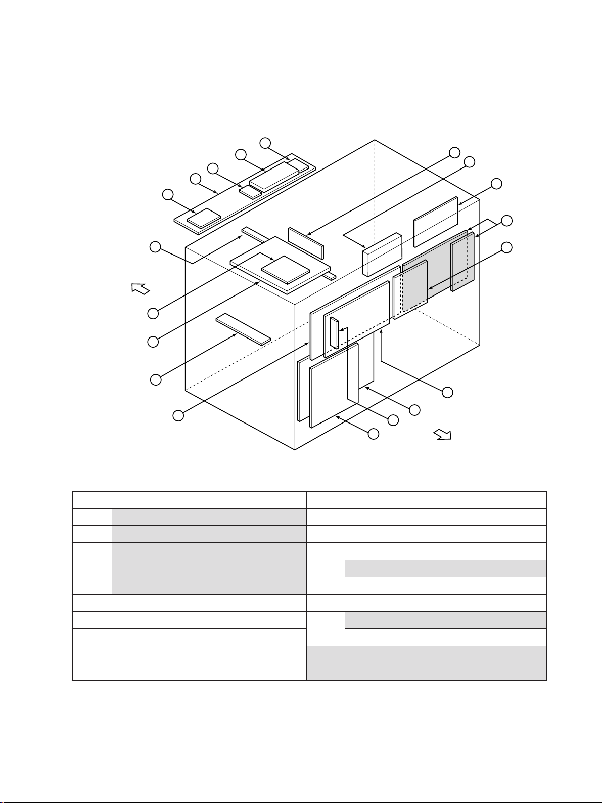
(5) Heaters and lamps
Parts list
Symbol
EXP EXPO-LAMP Exposes the original Halogen lamp 18 13
HTR HTR-LAMP (Heater lamp) Fixing Halogen lamp 25 6
ERS LP-ERS Discharges the drum LED 22 27
Code name
(Exposure lamp) 180W
(Discharge LED PC board)
Function
Remarks
900W
(100V series)
1100W
(200V series)
Page Item
DHU
DHL D-HTR-L (Damp heater L)
DHU2 D-HTR-U2 Keeps optical mirrors warm Cement resistor 8 24
D-HTR-U (Damp heater U) Keeps optical system warm
Keeps the drum and transfer/separation
charger case warm
(Damp heater for mirror)
Cement resistor 11 20
Cement resistor 3 30
(6) PC boards
Symbol
LGC PWA-F-LGC-220 Controls the entire copier 7 27
(Logic PC board)
DSP PWA-F-DSP-230 Controls the control panel 2 21
(Display PC board)
KEY PWA-F-KEY-230 Controls operation keys 2 22
(Key PC board)
PNL PWA-F-PNL-230 Controls operation keys 2 23
(Panel PC board)
CNT PWA-F-CNT-230 Controls operation keys 2 24
Code name
Function
Remarks
Parts list
Page Item
(Control panel PC board)
LCD K-LCD-TOUCH-230 LCD and touch panel 2 27
(LCD PC board)
IMG PWA-F-IMG-220 Controls image reading and 8 34
(Image process PC board) processing
SDV PWA-F-SDV-220 (Scanning Controls the scanning motor drive 8 33
motor drive PC board)
CCD PWA-F-CCD-220 Photoelectric transfer by CCD (11 19)
(CCD PC board)
December 1998 © TOSHIBA 2 -10 2470 OUTLINE OF THE MACHINE
Page 5
(6) PC boards
Symbol
ERS LP-ERS-130 Discharge LED 22 27
(Discharge LED PC board)
SFB PWA-F-SFB-220 (Manual
size detection PC board)
FUS PWA-F-FUS-351 Fuse for the damp heater circuit 3 31
(Fuse PC board)
SYS PWA-F-SYS-222 Controls the entire system 7 17
(System PC board)
PMA1 PMA-T222S1 ROM for destination 7 18
(ROM PC board)
PMB PWA-F-PMB-777 Stores the image data and holds the 7 19
(Page memory PC board) storage data
PMM KR-3007 (PM extension Holds the storage data when Option 7 20
memory PC board) employing the PM PC board
BRT PWA-F-BRT-503 Controls the smoothing process Option 103 10
(Smoothing PC board) when employing the GDI
Code name
Detect width of the manual feed size
Function
Remarks
Parts list
Page Item
14 16
DSI PWA-F-DSI-784 DSI interface board Option – –
PMA2 PMA-T222S2 ROM for program
(ROM PC board)
FAX PWA-F-SFX-500+PWA-F- FAX circuit Option
NCU-500* (F AX PC board)
PRT PWA-F-LANPRT-799+PWA- Printer controller Option
F-EXT-799(PRT PC board)
NIC (KR-7010/7011/7012) Network Interface board Option
(Network Interface Card PC board)
December 1998 © TOSHIBA 2 - 11 2470 OUTLINE OF THE MACHINE
Page 6

(7) Transformers
Symbol
HVT PS-HVT-220 Generates high voltages for
(Main charger) each process Minus
(Main charger grid) Minus
(Developer bias) Minus (plus
(Transfer) Plus
(Separation) AC+DC (minus)
(Transfer bias) Plus
(Pre-Cleaning discharge charge)
ACC PS-ACC-220 Supplies electrical power for 7 26
(Switching power supply) entire copier and controls the
Code name
exposure lamp
Function
Remarks
Mono unit type
selectable)
AC+DC (minus)
Parts list
Page Item
7 31
(8) Others
Parts list
Symbol
ATS SNR-ATC Reads toner density with a magnetic 23 33
Code name
(Auto-toner sensor) sensor
Function
Remarks
Page Item
THMS1 THMS1-HTR Detects temperature of the heat roller 26 19
(Heat-roller thermistor-1)
THMS2 THMS2-HTR Detects the temperature of the heat roller 26 19
(Heat-roller thermistor-2) end
THMS-D THMS-DRM Detects temperature of atomosphere 23 32
(Drum thermistor) around the drum
THERMO1
THERMO2
HDD KQ-2011 Stores the storage data when Option 103 8
K-THERMO-HTR Prevents abnormal heating of heat roller 26 8
(Thermostat)
THERMO-SCN Prevents abnormal heating of the 18 12
(Thermostat) exposure lamp
(Hard disk drive) employing the PMB
December 1998 © TOSHIBA 2 - 12 2470 OUTLINE OF THE MACHINE
Page 7

2.4 Removal of Covers and PC Boards
2.4.1 Removal of covers
[A] Front cover
(1) Open the front cover.
(2) Remove the pins on the hinges at both ends (1
each).
[A]
[B] Rear cover
(1) Remove the 9 screws.
[C] Upper exit cover
(1) Open the front cover and remove the 3 screws.
[D] Lower exit cover
(1) Remove the 5 screws.
[E] Upper feed cover
(1) Open the front cover and the bypass tray and
then remove the 4 screws.
[B]
[C]
[D]
[E]
[F] Feed cover (left and right)
(1) Remove the paper feed cover.
(2) When removing the left feed cover, open the
front cover.
[A]
[B]
(3) Remove the screws (2 on each side).
[F]
December 1998 © TOSHIBA 2 - 16 2470 OUTLINE OF THE MACHINE
Bypass tray
[F]
Page 8

9. PRINTING
9.1 Introduction
Electrical signals which are converted in the scanning portion are processed to the image signals in the
image process portion and the image signals light up the laser diode in the laser drive portion.
The laser beams are irradiated on a photosensitive surface after passing through the lens, polygonal
mirror, fθ lenses and mirrors.
As this set of components is very susceptible to dust, they are assembled in a clean room. Also, they are
adjusted to a high quality.
For this reason, this unit should not be disassembled unnecessarily in the field.
Laser unit
Laser diode
Polygonal mirror motor
Polygonal mirror
[Exit side]
Polygonal mirror
motor drive board
Lens-1
[Front side]
Polygonal mirror motor
HSYNC detection
mirror
Laser drive board
To the drum
Lens
[Rear side]
Mirror-1
HSYNC detection board
Slit glass (Laser light window)
Lens
Aperture
Lens-2
Mirror-2
[Feed side]
Fig. 9.1-1 Laser scanning unit overview
December 1998 © TOSHIBA 9 - 1 2470 PRINTING
Page 9

Rear side
Laser drive
board
Feed side
Front side
Exit side
Polygonal motor drive board
Polygonal motor
Fig. 9.1-2 Laser optical unit overview
2470 PRINTING 9 - 2 December 1998 © TOSHIBA
Page 10

9.2 Structure
(1) Laser Unit
The laser unit comprises a laser diode, finite lens and aperture.
1 Laser diode
The laser diode is compact, efficient, low-priced, operates on lower power, and has a long life.
However, it is sensitive to heat.
Laser diode controls emission of laser beams based on the laser control (ON/OFF) signals from
the laser drive board.
2 LASER SAFETY
The beam of the semiconductor laser is itself extremely weak (about 5 mW), but focusing the
parallel rays results in an increase in energy to which extended exposure is hazardous.
The laser optical system of the digital plain paper copier is encased in metal which in turn is
housed in the external cover. There is thus no risk of leaks during use, nor during normal servicing.
Note, however, that the laser beam is not visible, and extreme care must be exercised when
servicing involves focusing the laser. Such operations are hazardous and must not be attempted
unless you are specifically trained to work in this area.
The warning label shown below is attached on the left side of the upper inner cover.
DANGER–INVISIBLE LASER RADIATION WHEN OPTICAL UNIT OPEN OR DRUM UNIT REMOVED
AND INTERLOCK DEFEATED. AVOID DIRECT EXPOSURE TO BEAM.
VORSICHT–UNSICHTBARE LASERSTRAHLUNG. WENN DIE ABDECKUNG GEÖFFNET ODER
DIE TROMMEL ENTFERNT UND DIE VERRIEGELUNG UNWIRKSAM GEMACHT WIRD.
NICHT DIREKT DEM STRAHL AUSSETZEN.
DANGER–RAYON LASER INVISIBLE LORSQUE LE BLOC OPTIQUE EST OUVERT, LE
TAMBOUR RETIRE ET LE VERROUILLAGE HORS D’USAGE.
EVITER L’EXPOSITION DIRECTE AU RAYON.
[CAUTION]
• Do not insert tools that are highly reflective into the path of the laser beam.
• Remove all watches, rings, bracelets, etc.
December 1998 © TOSHIBA 9 - 3 2470 PRINTING
Page 11

E
D
C
16.8 System control circuit (PWA-SYS) 24/29
39
40
38
37
GND
32
SA23-1
12A4
13A1
36
SA22-1
13A1
35
SA21-1
13A1
34
SA20-1
12A7
33
SA0-1A
12A4
SA1-1
SA2-1
12A4
SA3-1
12A4
303231
SA4-1
12A4
29
SA5-1
12A4
282526
27
SA6-1
12A4
SA7-1
12A4
SA8-1
12A4
2421221920
23
SA11-1
SA10-1
SA12-1
SA9-1
12A4
12A4
12A4
12A4
SA13-1
12A4
SA14-1
12A4
18
SA15-1
12A4
17
SA16-1
12A4
SA17-1
12A4
SA18-1
12A4
141615
SA19-1
12A4
12
13
SBHE-0A
13A1
13A4
B
11
AEN-0A
10
IORDY-1
5E8 13E3
9876543
SD4-1A
SD3-1A
SD1-1A
SD0-1A
SD2-1A
12A1
12A1
12A1
12A1
12A1
12A1
SD5-1A
12A1
2
SD6-1A
12A1
A
TX24R10
J73
GDI IMG DATA
1
VDD
(NT5V) (NT5V)
SD7-1A
4
79
80
78
77
GND
5
SMEMW-0A
SMEMR-0A
13A5
13A5
12A4
67
76
SA26-1
12A4
75
SA25-1
12A4
74
SA24-1
13E3
73
IO16-0
13E3
NC
MEM16-0
69
686566
67
707271
NC
B14
B13
B12
GND
6461625960
63
GDDAK-0A
GDIRQ-1
GDDRQ-1
13E6
13A4
13E6
B11
B10
B9B8B7
SIOWR-0A
SIORD-0A
13A4
13A4
B6
TX24R10
J73
SD10-1A
SD9-1A
12A1
A3
42
SD8-1A
12A1
A2
[CN80][CN80]
VDD
J71
A1
53313V
57
SRDY-0
B3
RSTGD-1A
13A5
B1
B2
545655
NT3.3
SD14-1A
12A1
12A1
A7
A8
SD12-1A
SD13-1A
12A1
A6
SD11-1A
12A1
12A1
A5
A4
SD15-1A
12A1
A13
A14
A12
A10
A11
A9
58
13E3
B4
B5
51
524149484746454443
50
53
PDAT0-1
PDAT1-1
PDAT2-1
PDAT3-1
PHDEN-0
PVDEN-0
PRCLK-0
PDCLK-0
PHSYN-0
SDAT0-1
SDAT1-1
SDAT2-1
SDAT3-1
23D5
23B3
23D5
23B3
23C5
23C5
24
29
E
D
C
23B3
23D5
23B3
23B3
23C5
23B3
23C5
B
SHDEN-0
23C5
SVDEN-0
23A3
SDCLK-1
23A3
A
December 1998 © TOSHIBA 16 - 75 2470 ELECTRIC CIRCUIT DIAGRAM
8763452
Page 12

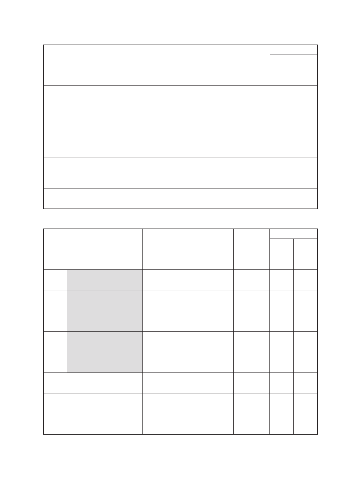
21.6 Hard Disk Unit (KQ-2011)
1. When performing the installation, turn off the
power switch of the copier and unplug the
power cord from the outlet.
2. <<Unpacking Procedure>>
Open the carton box.
3. Tak e out the hard disk unit and the accessories.
Note) P a y sufficient care when carrying the hard
disk unit. (See the sketch.)
The accessories include the following.
• Retaining bracket
• Connection harness
• BID screw (M4 x 8) (3 pcs.)
• BID screw (M3 x 4) (4 pcs.)
6
8
7
6
December 1998 © TOSHIBA 21 - 25 2470 UNPACKING INSTRUCTIONS
Page 13

21.7 Smoothing Unit (BRT Board) (KR-
3015)
1. When performing the installation, turn off the
power switch of the copier and unplug the
power cord from the outlet.
2. <<Unpacking Procedure>>
Open the carton box.
3. Take out the inter nal extension board and
locking support.
4. <<Installation Procedures>>
Remove the glass fix (with 2 screws).
2470 UNPACKING INSTRUCTIONS 21 - 28 December 1998 © TOSHIBA
Page 14

1.5 System list
STAPLE-600
KA-2060PC
MP-1501A4
MP-1501LT
MR-3006A,MR-3006E
RADF
MU-8
MU-10
KR-3015
KQ-2011
MY-1006
KR-8002
MD-5004
MJ-1003
KE-2060
Staple cartridge
Finisher
Original cover
HDD
Slot cover
ADU
BRT board
MF-2460U
MF-2460E
KR-6012AS(ASD)
KR-6012HK(ASD)
KR-6012AU(AVD)
KR-7010
KR-7011
KR-7012
KR-7015
Damp heater
DSI board
ROM
FAX board
RAM board
Cassette module
Key counter
KD-1003
KD-2009
KK-2460
LCF
KR-3007
Extension memory
board for PM
PFP(2 cassettes)
Working tray
PFP(1 cassette)
NIC board
PRT board
EXTENSION
board
2470 SPECIFICATIONS 1 - 4 December 1998 © TOSHIBA
 Loading...