

Page 1

BSI(Service Note) TOSHIBA
TOSHIBA TEC CORPORATION
2-4-1, Shibakoen, Minato-ku, TOKYO, 105-8524 JAPAN
BSI No
F98L458
SUBJECT
FC-70 Packing Instruction for Transport
MODEL
CATEGORY
Treatment in the field
----------
CONTENT
These instructions are to prevents the following problems occurring caused by vibration during transit.
FC70
FIELD APPLICATION
Others
FACTORY APPLICATION
* Pitch line problems include impulse line problems.
* Leakage of fusing oil
UNIT
Other
Date
98/12/15
----
These instructions will be of use in the following situations.
* When the copier is transported after it is unpacked and set up.
* When the copier is transported to another place or returned by the user.
*NOTE
Save all packing materials because they are used for transport.
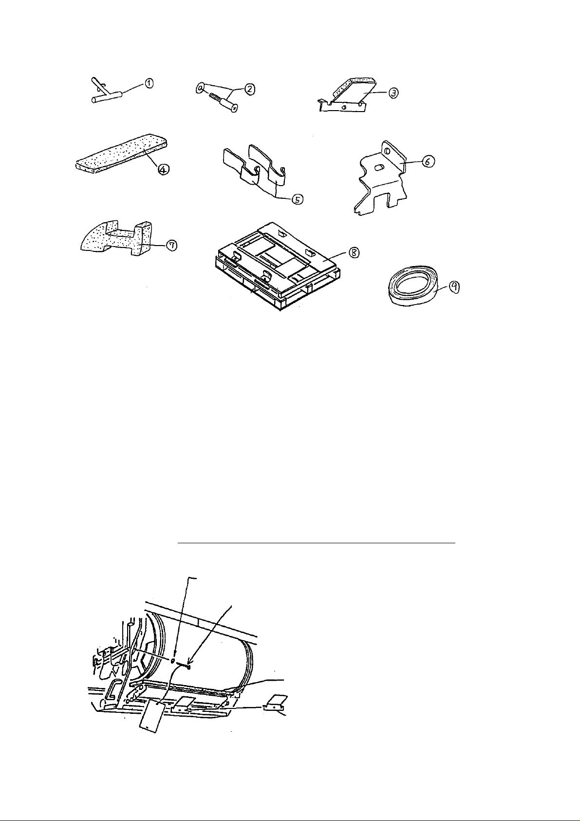
The following packing materials are needed for transport.
Page 2
BSI No. F98L458 Page 2
1.1st scanner locking pin 2.Pin locking the transfer drum shaft (iincluding the washer)
3. Cushioned holding plate of the static charge unit 4. Sponge 5. Stops in the
transfer drum unit rails(X2) 6. Holding plate in the charge neutralizing corona
assembly
7.Cushion packed above the transfer drum lock release handle 8.Basic plate
Packing procedure
Before conducting the procedure, make sure that you thoroughly understand the following points.
* NOTE
* Inject the fusing oil into the fuser oil bottle in the user's place of work in order to prevent oil
leakage during transit.
* Drain the fusing oil out of the bottle when the copier is transported.
* Fill the syringe with 10ml of oil three times and inject it into the bottle. 30ml of oil can make 20
copies of A3 size. As a guide for this, add the oil to the bottle.
1. Pull out the transfer drum and remove the transfer unit cover.
2. Attach the sponge and the cushioned holding plate of the static charge unit as shown.
(Insert the sponge between the static charge unit and the joint of the transfer drum
in order to
prevent the transfer film being dented.)
3. Screw the pin locking the transfer drum shaft (including the washer) as shown.
Washer
Pin locking the transfer drum
shaft
Sponge
Cushioned holding plate of the static
Page 3

BSI No. F98L458 Page 3
4. Tape the transfer drum back flange as shown.
-> Do not tape the rubber part of the flange.
Tape up
Note: Tape up firmly
Note: Do not tape the rubber portion
Transfer drum
5. Attach the holding plate in the charge neutralizing unit corona assembly and tape the two stops
in the transfer drum unit rails as shown.
6. Tape the two stops in the transfer drum unit rails as if they are coiling on the rail.
Tape the two stops in the transfer drum
unit rails
Holding plate in the charge neutralizing
corona assmbly
6. Attach the transfer unit cover and install the transfer drum.
7. Attach the cushion packed above the transfer drum lock release handle and tape it up while the
transfer unit lock lever is released as shown.
-> Do not tape on the label.
Note: Do not tape on the label
Tape up
Cushion packed above the transfer drum lock release handle
8. Tape the toner hopper as shown.
-> Tape the rails of right and left.
Page 4

Tape the toner hopper up on the
right and left rails
9. Attach the 1st scanner locking pin and tape it up as shown.
BSI No. F98L458 Page 4
Tape the 1st scanner locking pin
10. Tape the copier as shown.
Tapes
Tapes
Tapes
Tapes
11. Put the copier on the basic plate and fasten it.
If there is a box, cover the copier with it.
Tapes
Page 5

BSI No. F98L458 Page 5
 Loading...