

Page 1
BSI(Service Note) TOSHIBA
TOSHIBA TEC CORPORATION
2-4-1, Shibakoen, Minato-ku, TOKYO, 105-8524 JAPAN
BSI No
F98E291
SUBJECT
ENERGY STAR/ Tier 2 (EUD)
MODEL
CATEGORY
Safety standard Related
From Apr. 1998
CONTENT
To comply with the standard value of ENERGY STAR (Tier 2) for EUD in the above models, the
following changes have been made. Also, for conformity with other parts, some changes have been
made for regions other than Europe.
A75
FIELD APPLICATION
Others
FACTORY APPLICATION
Date
98/05/27
DTM-F8110/8202/8205/8310
UNIT
Other, Software, Electrical
Circuit
[ Changed Content ]
1. Setting change of Auto Power Save and Auto Shut-Off Mode at the time of shipment
Setting at the time of shipment in the above modes has been made not to permit operation but
the setting values have been changed as follows.
Before Change After Change
Auto energy saving
(08-11)
Auto shut-off
(08-56)
Note) *The power switch automatically goes off when the [Auto shut-off] mode is operated.
Return to the READY condition can be made by turning the power switch ON.
* Operation time of [Auto energy saving] [Auto shut-off] can be extended to a maximum of
240 minutes.
*The power supply OFF in the [Auto shut-off] mode has priority over the Weekly Timer.
Therefore, when the power supply is turned off in the [Auto shut-off] mode, the power
return function of the Weekly Timer cannot operated.
*If the setting value changes, refer to BSI/F98C249.
2. Change of power supply switch to one with an electromagnetic reset function
In order to be able to reset the MAIN SW using software, change has been made to the power
supply switch by giving it an electromagnetic reset function. This switch has a MAIN SW inside
coil for resetting and the switch goes off when DC24V is added to the coil.
The combination of the switch terminal and the harness connection has also been changed as
shown below.
0
(No function)
20
(No function)
3
(Function after fifteen minutes)
12
(Function after ninety minutes)
Page 2

Coil for reset
-> 1
2 <-
-> 3
-> 4
5 <-
-> 6
BSI No. F98E291 Page 2
Current New
Terminal Housing Color Harness Color Housing Color Harness Color
1 Blue Pink White Orange
2 Yellow Brown Yellow White
3 White Purple Blue Yellow
4 Blue Yellow White Purple
5 Yellow White Yellow Brown
6 White Orange Blue Pink
+ -- -- White Red
- -- -- White White
AC Wire-Harness Connection Diagram (MAIN SW area)
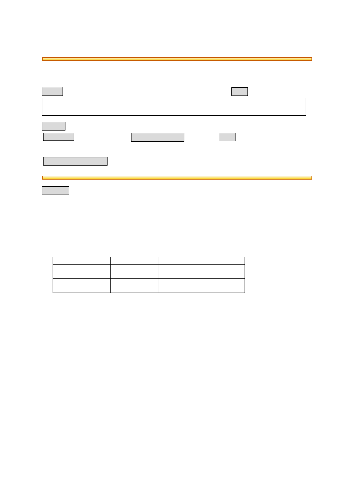
3. Change of logic circuit (PWA-LGC)
In order to drive the power supply switch with the above magnetic reset function, the logic circuit
has been changed.
PWA-LGC has been changed to all regions.
(Details)
Connection of the 130 pin of IC31 (95CO63F) and the 14 pin of IC33 (62308F)l
Connection of the 15 pin of IC33 (62308F) and the A9 pin of J8l
To distinguish easily between the current and new logic PC boards, the color of the PC board l
has been changed from white to yellow.
Note) The current logic PC board should never attached to machines complying with the
ENERGY STAR (Tier 2).
If there is an excess current flow to the MAIN SW, it might possibly break.
Page 3
Current
Color: White
(J326)
PWA-LGC
SSR
---- RSTSW
MAIN-SW
(-)
(+)
BSI No. F98E291 Page 3
IC31
(95C063F)
130 pin IC33
14 pin 15 pin
(62308F)
A9 pin
J8
Empty pin Empty pin
DG
New
Color: yellow
Connection Connection
IC31
(95C063F)
130 pin
14 pin
IC33
(62308F)
15 pin
A9 pin
J8
CUT
DG
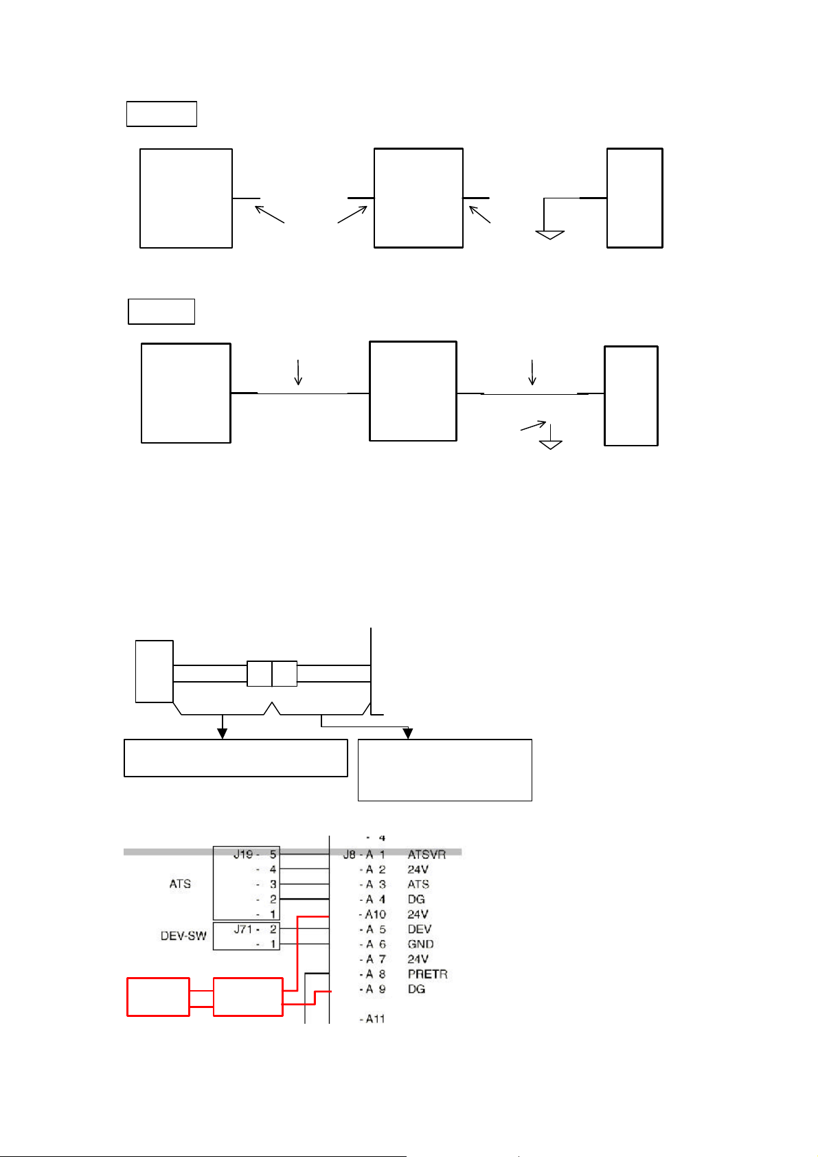
4. Wiring Change (Harness added)
In order to drive the switch with the power supply magnetic reset function, the wiring has been
changed as shown below.
Between the connector J8 (A9, A10) of the PWA-LGC and the MAIN switch (+, - terminal) have
been connected by two new harnesses.
Also, the harness of the PWA-LGC side is not considered as a service part but is a part of the
previous harness (WH-LGC-HVT).
MAIN SW
(+)
(-)
Added harness
(WH-RSTSW-154 / 4402322090)
* DC Connection Schematics Diagram (Area C6)
1 J326 1
2 2
J8-A10
J8-A9
Added harness
* Included as part of current
WH-LGC-HVT (N/A part)
Page 4

BSI No. F98E291 Page 4
5. MAIN ROM change
Addition of the electric magnetic reset function driving control of the MAIN SW.
MAIN ROM has been changed to all regions.
(MAIN ROM Version)
Ver. 02 -> 03
[ Combinations of ROM Versions ]
The MAIN, LCD and PNL should never be operated except in the following combinations. As
only the following combinations can have their operation checked, errors could well occur
with other combinations.
MAIN 03
LCD 010
PNL 000
Page 5

History of ROM Version
No. MAIN LCD PNL
Application
1997/12 WL710702
(TAD)
BL710182
(EUD)
1998/3
1998/4
BSI No. F98E291 Page 5
For LanguagesFactory
Model Each
Language
01 010
010 000 ALL ALL F98C227 * Improvement of AC Key
02
010 000 ALL ALL F98E291 * Addition of MAIN SW
03
000 ALL ALL F97L114 * Change of quantity of
BSI No Content
copies able to be
stacked and stapled in
the cover/sheet insertion
mode
* Correction of jamming in
the sheet insertion mode
* Correction of poor
image visibility caused
by the automatic sort
setting value.
* Correction of editing
position adjustment
setting value
* Correction of error for
access code input at
standby.
response for access
code standby.
* Improvement of aging
mode release method
electromagnetic reset
function driving control
(ENERGY STAR Tier 2)
Page 6

BSI No. F98E291 Page 6
6. Applied ENERGY STAR label
The ENERGY STAR label (LBL-ENERGY-T) has been attached to the front cover.
7. Change of parts connected with the MAIN SW electromagnetic reset function
The MAIN SW with the electromagnetic reset function is bigger than the current one. The
following parts have been changed at the same time.
Also, (2), (3), (5) have been changed to all regions.
(1) MAIN SW area cover (K-COVER-R-L-F-T)
(2) Angle (FRAME-AGL-F-EN) Change for all regions
(3) Angle bracket (BKT-ANGLE-F-EN) Change for all regions
Page 7

(4) MAIN SW bracket (BKT-SW-MAIN)
BSI No. F98E291 Page 7
(5) Harness cover (COV-WH-AGL-F-EN) Change for all regions
Page 8

BSI No. F98E291 Page 8
[Change/ Addition Part No.]
Parts enclosed by bold lines have been changed for all regions.
(Other parts have been changed for EUD only.)
P/I Before Change After Change Note P I R
3-1B 4401901170
K-COVER-R-L-F-T
6-1 4401787200
FRAME-AGL-F-EN
4402303100
K-COVER-R-L-F-T
4402303050
FRAME-AGL-F-EN
Applied to all
regions
C D C
C D C
(N/A parts)
6-2 4401787290
BKT-ANGLE-F-EN
6-3B 4401787330
BKT-SW-MAIN
6-5B 4843231592
SW-AJ921100Z301
4402303060
BKT-ANGLE-F-EN
4402303070
BKT-SW-MAIN
4402322720
SZ-A8G109324
Applied to all
regions
SW with
electromagne
C D C
C D C
C D C
tic reset
function
6-8 4401787610
COV-WH-AGL-F-EN
4402303080
COV-WH-AGL-F-EN
Applied to all
regions
C B C
6-46B ---- 4402322090
WH-RSTSW-154
6-47B ---- 4843391656
WIRE/B-SKB-1M
1-54B ---- 4401910990
LBL-ENERGY-T
64-14
101-0
101-1 4402889210
4402889160
PWA-F-LGC-156
PWB-F-LGC-156
4402889170
PWA-F-LGC-156
4402889220
PWB-F-LGC-156
Applied to all
regions
Applied to all
regions
(N/A parts)
64-22 4402897400
PRA-157M-02
4402897410
PRA-157M-03
Applied to all
regions
P: Contents of Change I: Interchangeability R: Reasons for Change
A D C
A D C
A D C
C B C
C - C
C B C
 Loading...