

Page 1
BSI(Service Note) TOSHIBA
TOSHIBA TEC CORPORATION
2-4-1, Shibakoen, Minato-ku, TOKYO, 105-8524 JAPAN
BSI No
F98A149
SUBJECT
Addition to the Service Manual
MODEL
CATEGORY
Correction of Service Manual
---------
CONTENT
If an obstacle is put in the lower bin unit, it must still be made to stop moving without any phase
sideslip. So a
added to 1st production machines. Since this
Service Manual, it's details are given in this BSI. In order to facilitate the removal of the transport
roller, a new step order has been applied to present production machines.
MG2012
FACTORY APPLICATION
object detection switch accompanied by current detection circuit has been
Correct Page
2-5
FIELD APPLICATION
Others
object detection switch was not mentioned in the
Change Point
Date
UNIT
Documents
98/02/10
----
2-31
3-8
5-13
5-14
A-1
Sorter controller input (2/2) Fig.2-105
3. Bin shift motor control Fig. 2-506
C. Removal transport roller
Motor/switch/solenoid/PCB etc. Fig.5-302
Motor/switch/solenoid/PCB etc. Table 5-302
A. Circuit Diagram
a-1.pdf
3-8.pdf
2-5.pdf
2-31.pdf
5-13.pdf
5-14.pdf
Page 2
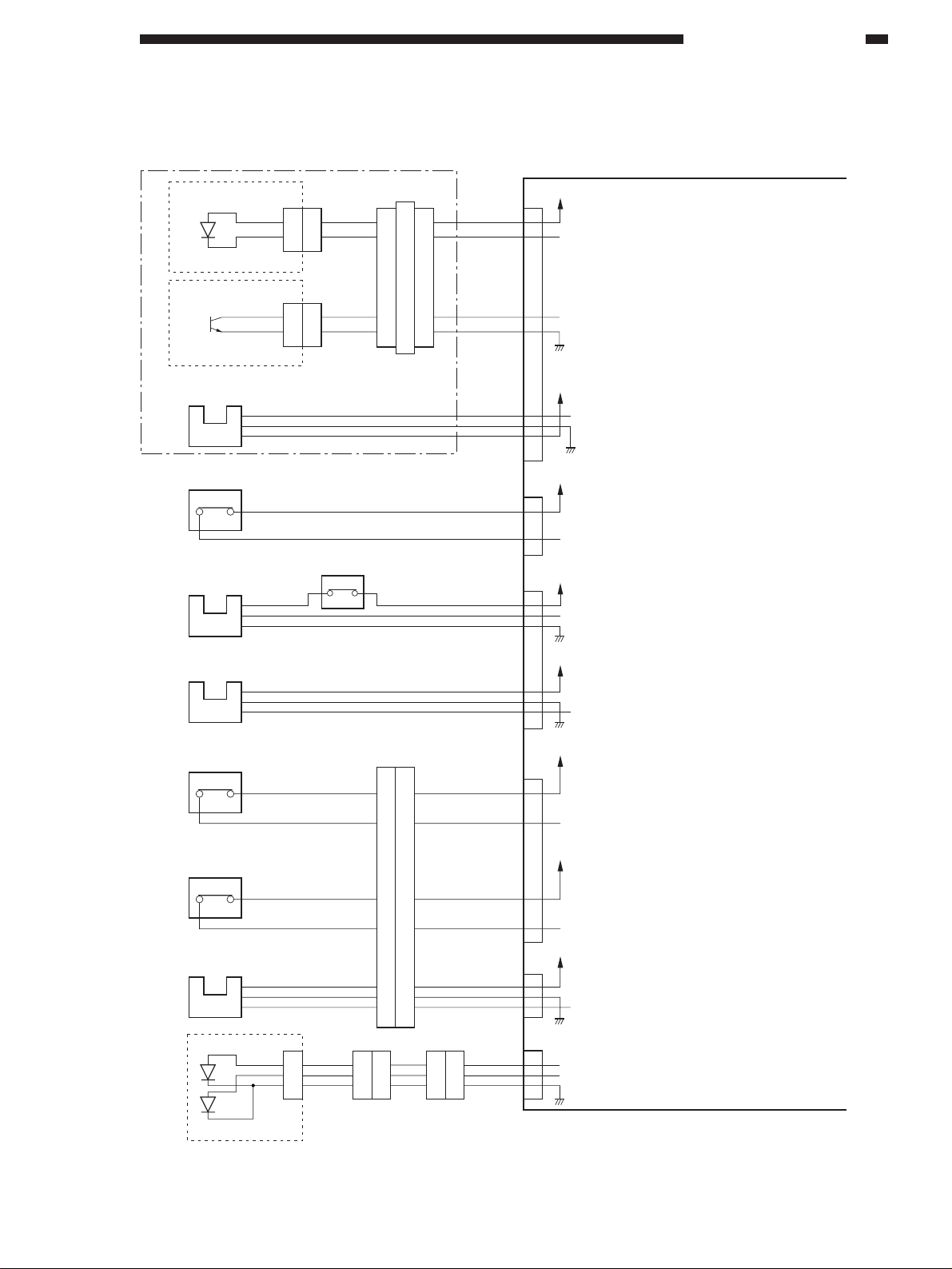
Inputs to the Sorter Controller (2/2)
Bin inside paper
sensor
S1
(light-emitting unit)
Bin inside paper
sensor
S2
(light-receiving unit)
Guide bar home
position sensor
1
2
3
PI3
J203
1
2
1
4
2
3
1
2
J108
J204
2
1
2
2
1
1
3
4
2.OPERATIONS AND TIMING
Sorter controller PCB
+5V
J4
1
2
BIN LED
When "1", the LED is turned on
(flashes).
3
4
PA CHE
When there is paper inside the bin,
"1"
+5V
6
7
8
STYGHP
When the guide bar is at
the home position, "1"
Joint switch
MS1
NO
Bin shift motor
clock sensor
Lead cam home
position sensor
Stapler unit cover
switch
PI1
PI2
COM
3
2
1
3
2
1
MS2
NO
Stapler unit home
position switch
COM
MS4
PI7
COM
3
2
1
NO
Stapler unit cover
sensor
S3
Objection detection switch
MS7
NO COM
J115
1
2
3
4
5
6
7
1
2
3
4
5
6
7
J301
J202 J104
1
2
4
1
4
2
4
1
3
2
1
4
+24V
J10
1
2
JOI SW
When the sorter is connected
to the copier, "1"
+5V
J5
1
3
2
SHIFT CLK
Pulse corresponding to
the rpm of the shift motor
+5V
4
6
5
CUMH
When the lead cam is at
the home position, "1"
+24V
J6
1
2
SPLOPN
When the stapler unit cover
is closed, "1"
+24V
3
4
3
2
1
J14
SPUHP
+5V
SPL COV
When the stapler unit
is at the home position
for swing operation, "1"
When the stapler unit cover
is closed, "1"
J3
1
4
3
1
2
4
SPL ED
HARI LED
When stapling is possible, "1"
When there are no staples, "1"
S4
Figure 2-105
2-5
Page 3
2.OPERATIONS AND TIMING
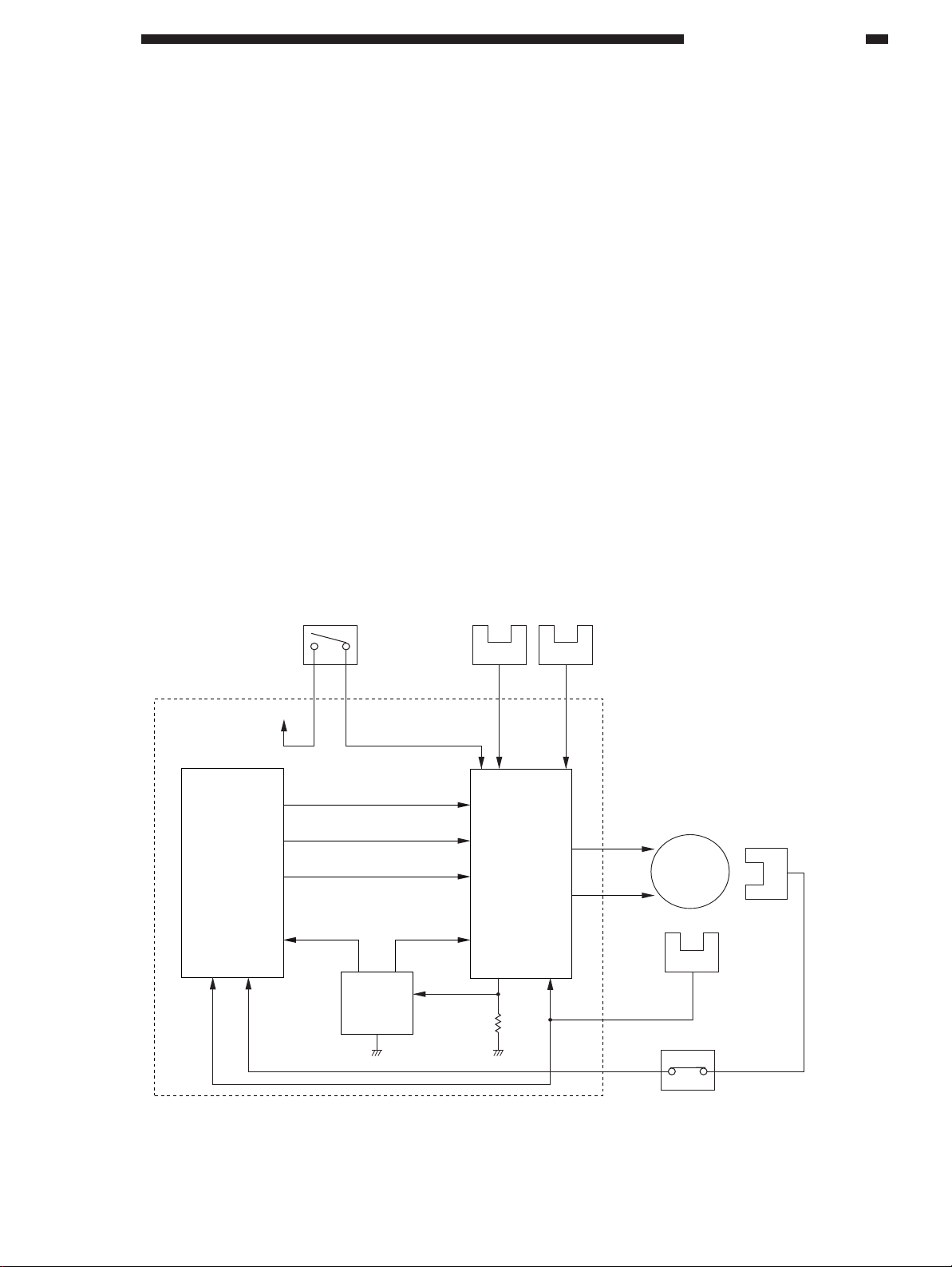
3. Controlling the Bin Shift Motor
Figure 2-506 shows the control circuit for the
bin shift motor.
The bin shift motor (M1) is a DC motor. This
motor is controlled by the drive circuit to raise and
lower the bin unit.
The bin unit raise/lower speed is detected and
controlled by the shift motor clock sensor.
The stop position of the bin unit is detected by
the lead cam home position sensor.
When the stapler unit is not at the home position, the 24 V po wer supply is cut off b y the stapler
home position switch to prevent the rotation of the
bin shift motor in order to avoid a collision of the bin
unit and the stapler unit.
Overrun is prevented b y the bin unit upper and
lower limit sensors.
A current detection circuit is also provided to
detect overcurrent when the bin unit contacts a f oreign object to stop the bin unit.
When an obstacle is found under the bin unit
raising the lead cam, the objection detection switch
opens and the shift motor stops transmitting clock
signals to the CPU. Therefore the CPU terminates
the shift motor.
Sorter controller PCB
Q1
CPU
Stapler home
position switch
ON
+24V
BMUP
BMDWN
PWM
MS4
Current
detection
circuit
Bin unit upper
limit sensor
PI4 PI5
Drive circuit
Bin unit lower
limit sensor
LCHP
Bin shift motor
M1
PI2
Lead cam home
position sensor
MS7
Shift motor clock
sensor
PI1
Figure 2-506
COMNO
Objection
detection switch
2-31
Page 4

3.MECHANICAL SYSTEM
III. FEEDING GUIDE UNIT
A. Removing the Feeding
Guide Unit
1) Remove the front co ver.
2) Remove the screw to take out the latch
lever holder .
2
Figure 3-301
3) Remove the latch lever , the latch and the
latch stay .
4) Remove the screw to take out the feeding
guide unit .
1
B. Removing the Feeder
Motor (M2)
1) Remove the rear cover.
2) Disconnect the connector and remove two
screws to take out the feeder motor .
3
2
1
Figure 3-303
7
3
6
5
C. Removing the Feed Roller
1) Remove the right cover, front cover, feeding
guide unit, rear cover and f eeder motor.
2) Remove feed roller block and gears .
3) Remove screw , and then, remove the feed
roller holder .
4) Remove the feed roller
1 4 5
2
3
4
Figure 3-302
Figure 3-304
3-8
Page 5

B. Motors, Switches, Solenoids and PCBs
5.TROUBLESHOOTING MALFUNCTIONS
1
M5
M4
M3
M1
M2
Figure 5-302
MS5
MS6
MS7
SW
MS1
MS3
MS4
MS2
2
5-13
Page 6

5.TROUBLESHOOTING MALFUNCTIONS
Motors, switches, solenoids and PCBs
Symbol Description Notation
M
Bin shift motor
Feeder motor
Guide bar swing motor
Stapler unit swing motor
Stapler motor
Joint switch
Stapler cover switch
Stapler safety switch
Stapler unit home position switch
No staple detection switch
No cartridge detection switch
Objection detection switch
Manual staple switch
Control panel PCB
Sorter controller PCB
M 1
M 2
M 3
M 4
M 5
MS 1
MS 2
MS 3
MS 4
MS 5
MS 6
MS 7
SW
1
2
T able 5-302
5-14
Page 7

A. GENERAL CIRCUIT DIAGRAM
A-1
 Loading...