

Page 1

BSI(Service Note) TOSHIBA
TOSHIBA TEC CORPORATION
2-4-1, Shibakoen, Minato-ku, TOKYO, 105-8524 JAPAN
BSI No
F97I037
SUBJECT
New Model 1560
MODEL
CATEGORY
New Model Description
CONTENT
The new model 1560 is based on the existing model 1550 with some small changes.
Therefore, this BSI will explain the changes, so a service manual and Service Parts List will be not
be provided.
1560
FIELD APPLICATION
Others
FACTORY APPLICATION
Date
UNIT
General
97/11/04
------
1. Contents
The bypass paper feeding capacity for the 1560 has been changed from single to stack feeding of 60
sheets. Moreover, for energy saving, when there has been no input for a fixed time, the main switch
will now automatically be turned "OFF". For bypass feeding area the 1560 uses the same bypass
paper feeding device as the 2060 (2860) and drive is provided through the main motor to the
aligning roller unit. As new electrical parts, there is an ON/OFF electromagnetic clutch in the feeding
roller and a bypass switch for paper-empty detection.
(The time until it goes off can be adjusted.)
The consumable parts and options are all common to the 1550 ones. However, when using the key
counter mounting kit KN-1550K, a hole has been added to the copier cover for easy installation.
2. Specification changes
2. 1) Bypass
Copying speed : 8 copies/minute ( all sizes)
Size : A3~A5-R
LD~ST-R
Paper stacking capacity : 60 copies
Copy paper size : 64~80g/m2 : 60 copies stacking
16~22lbs : 60 copies stacking
80~130g/m2 : single-sheet feeding
22~34lbs : single-sheet feeding
1. 2 Weight of machine: 38kg
1. 3 Size of a machine: W571 x D541 x H340mm
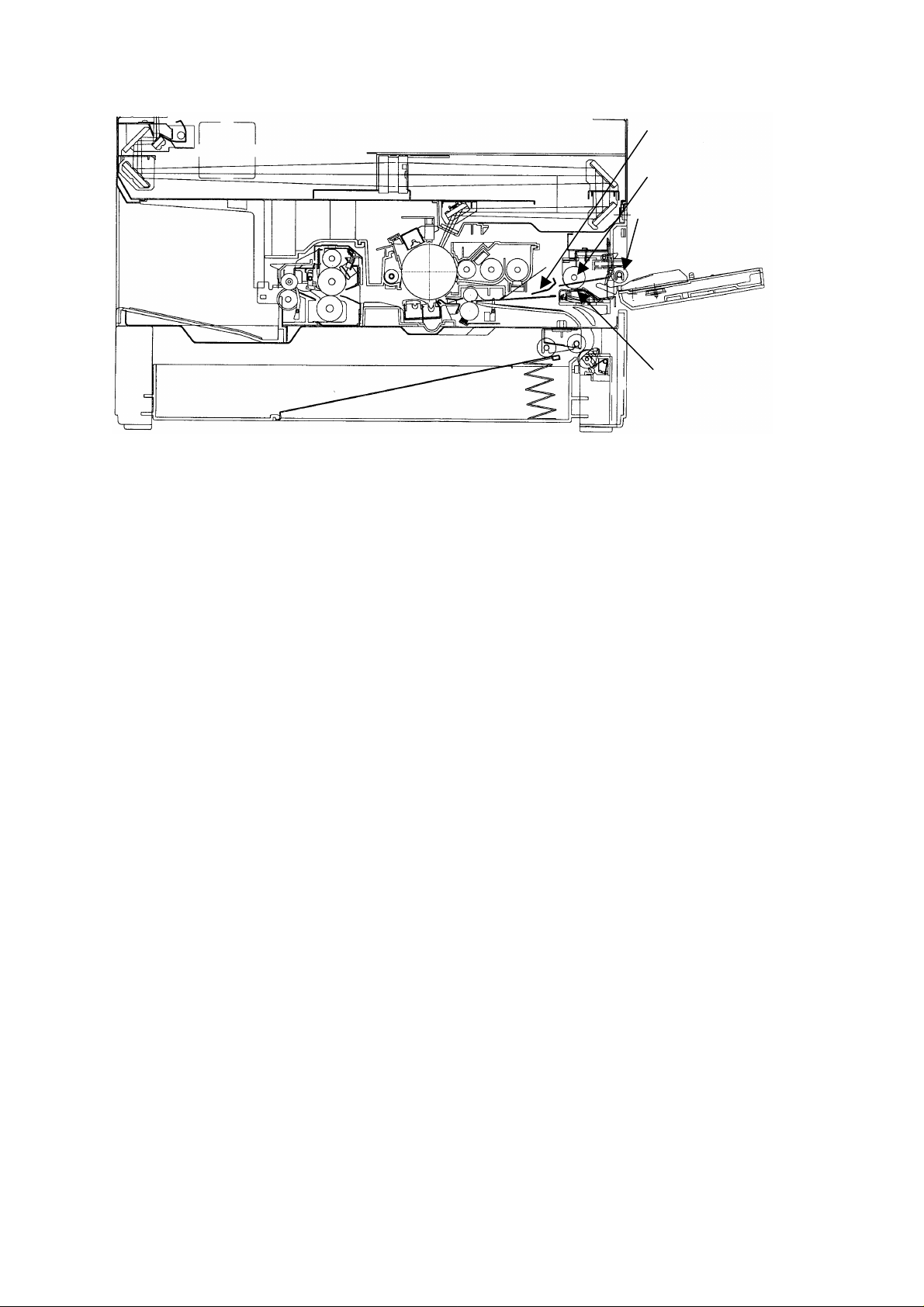
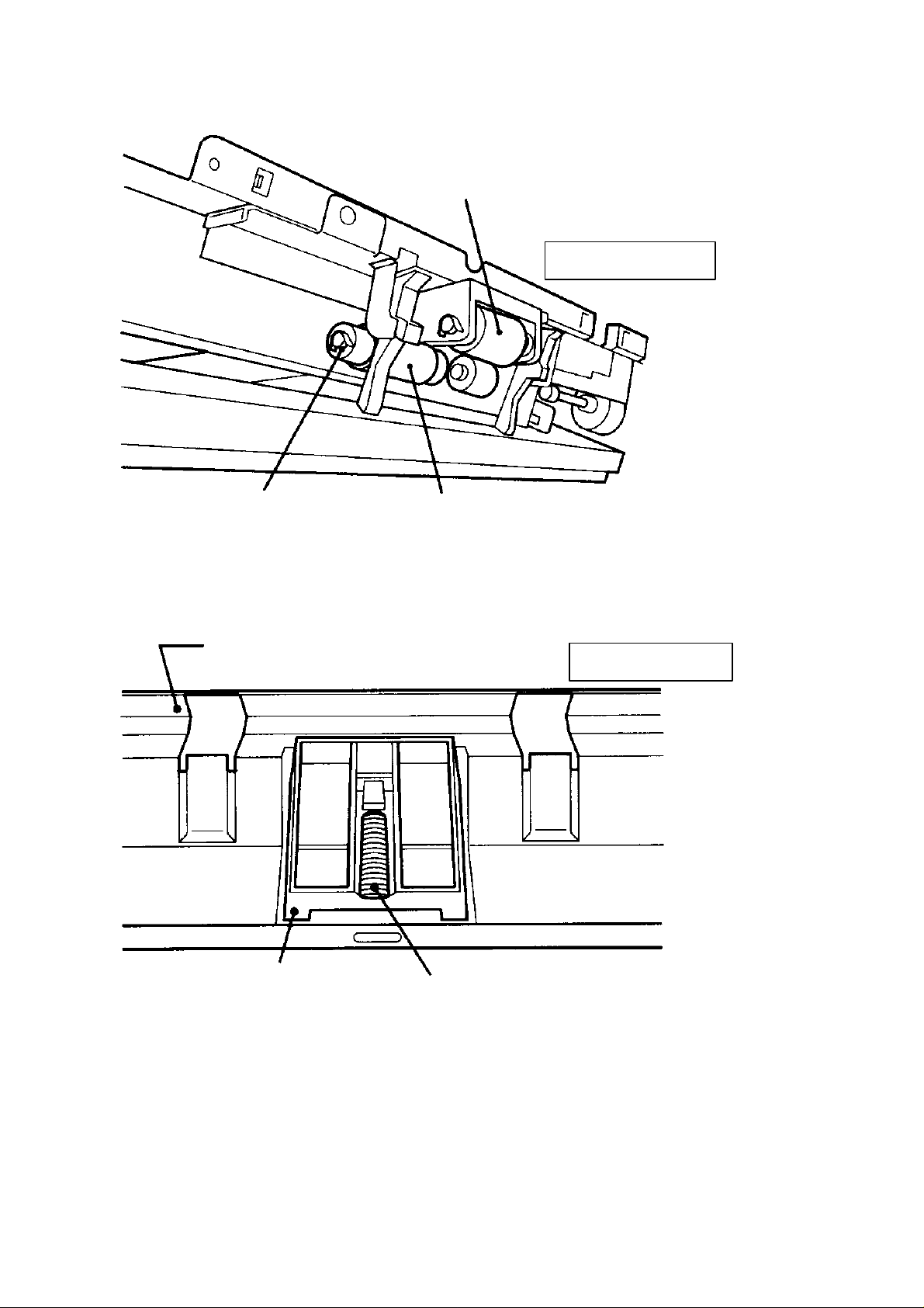
3. Bypass area/sectional view
Page 2
BSI No. F97I037 Page 2
Bypass paper guide
Bypass paper-feed roller
Bypass pick-up roller
Bypass separation pad
4. Operation Explanation "Bypass paper-feed copying"
(1) Insert the paper in the bypass paper-feed slot.
Switch ON the bypass
The bypass LED of the control panel lights up.
(2) Press the PRINT key
The main chager/transfer chager/separation charger/transfer bias/discharger lamp/LED eraser lamp
are turned ON/and the optical system fan motor rotates at a high speed.
The main motor comes ON~the drum/developert/heat roller/and paper-exit roller rotate.
(3) Bypass paper-feed operation
The manual feed clutch comes ON~the bypass pick-up roller/paper feed roller rotate.
Aligning operation (the paper reaches the aligning roller)~switch is turned on paper stop.
After a fixed time, the manual feed clutch goes OFF~ paper-feeding is finished.
(4) Thereafter, the paper-feeding operation is the same as with the cassette.
5. Disassembly and exchange
5. 1. Removal of door switch and main switch
(1) Remove the rear cover.
(2) Open the front cover and raise the upper unit.
(3) Remove the bypass paper-feed cover (2 screws).
(4) Remove the front support bracket (1 screw) of the bypass and take out the bypass tray. (See
Illustration A.)
(5) Remove the rear support bracket (1 screw). (See Illustration A.)
(6) Remove the bypass paper guides (upper/2 pieces) (1 screw each). (See Illustration A.)
(7) Remove the 2 screws of the bypass separation pad bracket. (See Illustration B.)
(8) Push down the pick-up roller and take out the separation pad bracket by pushing down the paper
stop lever and the arm of the paper sensor.
For the removal of the bypass paper feed roller, the separation pad and the clutch, details are given
later.
Page 3
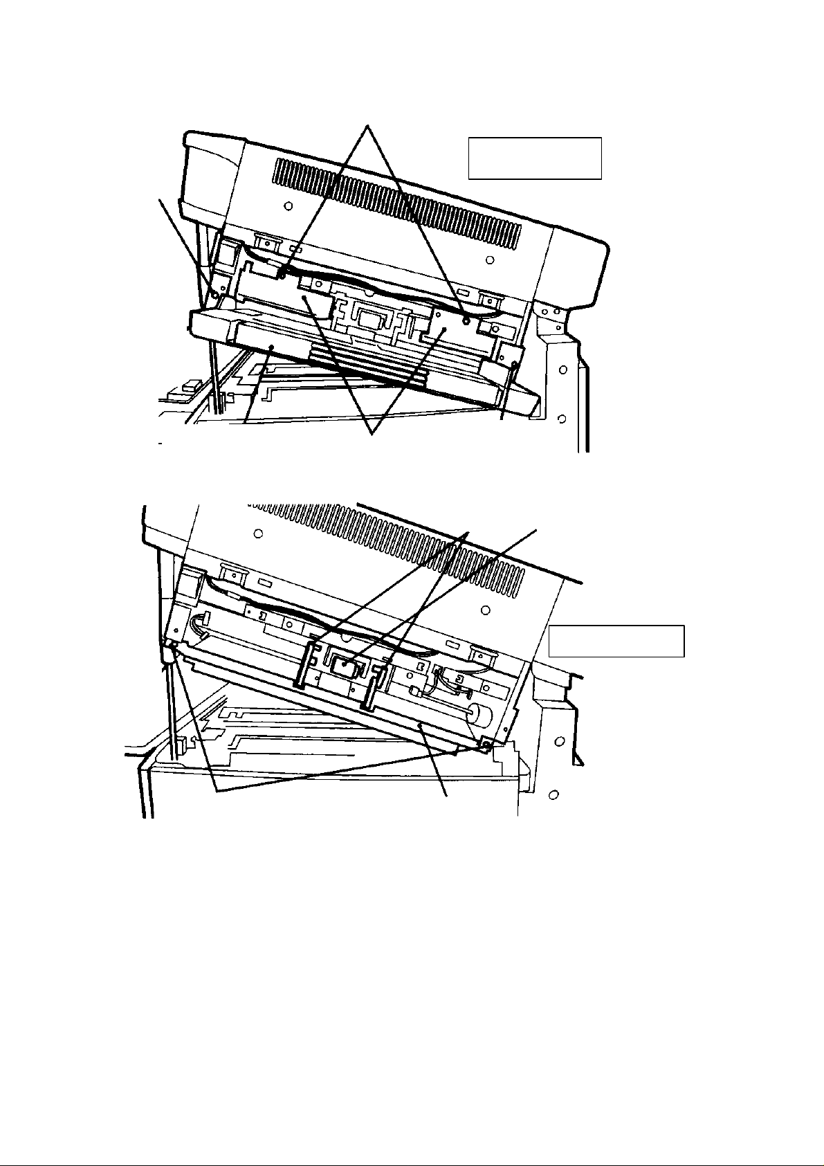
5. 1 (4)
<Illustration B>
BSI No. F97I037 Page 3
5. 1 (6)
<Illustration A>
Bypass tray
5. 1 (7)
Bypass paper guide
Paper stop lever
Separation pad
5. 1 (5)
Pick-up roller
(9) Remove the process unit, inner cover (upper) and the control panel.
(10) Remove the paper-feed side gas spring (E-ring, 1 piece). Then, open the original cover to
prevent the upper unit from falling down.
(11) Remove 1 screw of the paper guide and pull it out toward the front. (two paper guides can
removed at the same time.)(See Illustration C.)
(12) Remove the right cover.
(13) Remove the connector cover of the switch.
(14) Remove the 3 screws of the bracket fixing the switch. (See Illustration D.)
(15) Pull the bracket out with the harness connected.
< For removing the lens motor, details are given later. >
Page 4
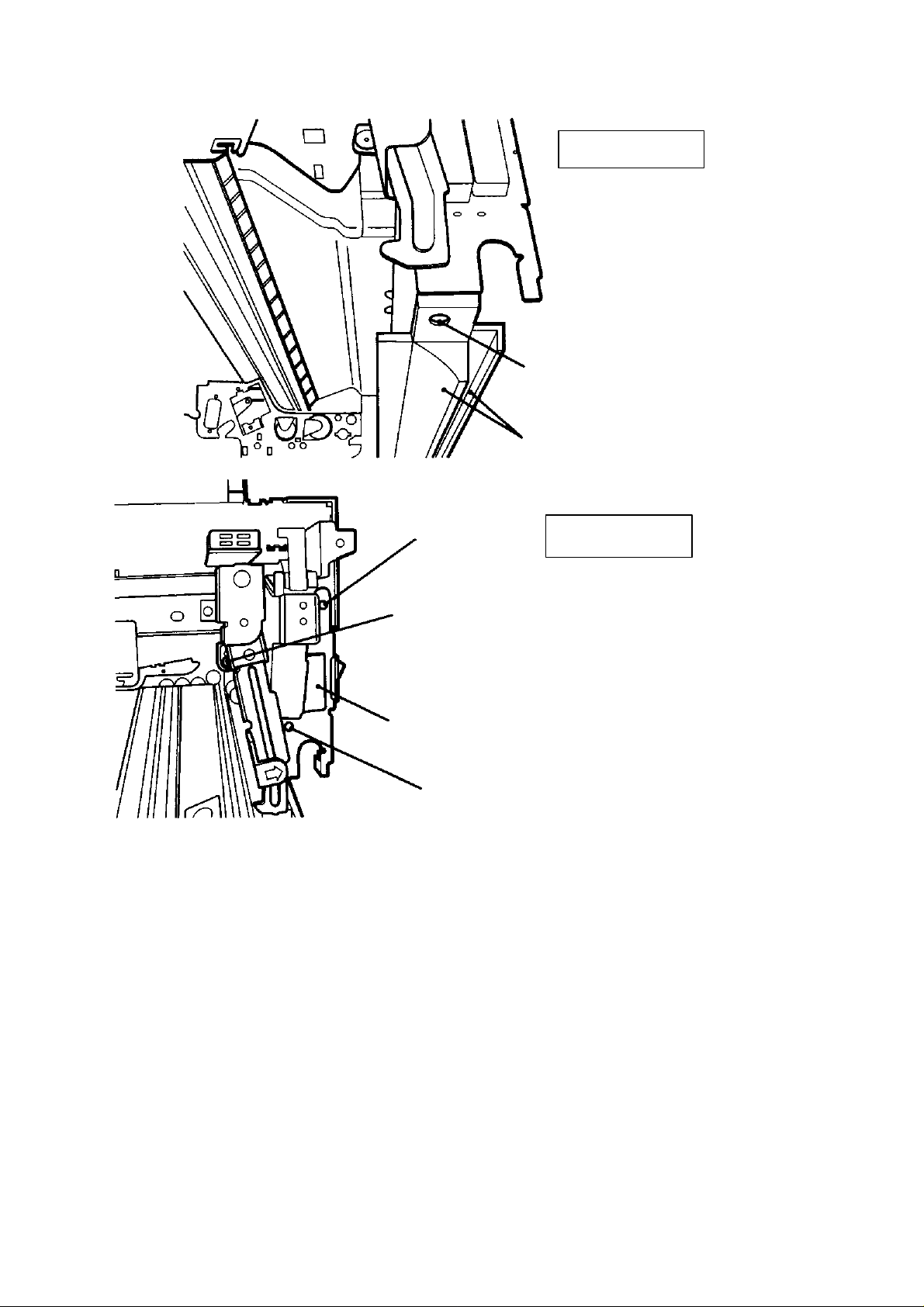
<Illustration C>
5. 1 (11)
Paper guide
BSI No. F97I037 Page 4
5. 1 (14)
5. 1 (14)
5. 1 (13)
<Illustration D>
Connector cover
5. 1 (14)
(16) Take out the main switch connector and remove the switch while pushing the switch pawl.
(17) Take out the door switch bracket (1 screw) and remove the bracket in the direction of the arrow.
(See Illustration E.)
(18) Take out the switch connector and remove the switch while pushing the switch pawl. When
reassembling, take care with the contacting of the connector.
Page 5
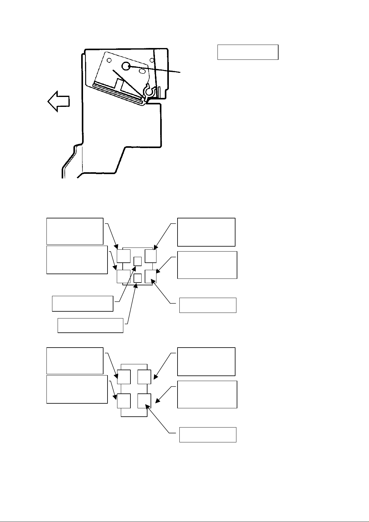
5. 1 (17)
BSI No. F97I037 Page 5
<Illustration E>
Main switch connector connecting diagram.
Harness: white
Connector: blue
Harness: white
Connector: yellow
1
3
5
42
6
Harness: red
Harness: gray
Door switch connector connecting diagram.
Harness: white
Connector: blue
1 3
Harness: white
Connector: white
2 4
Harness: black
Connector: blue
Harness: black
Connector: yellow
Terminal No.
Harness: black
Connector: blue
Harness: black
Connector: white
Terminal No.
5. 2 Removal of the bypass feed roller
(1)~(8) is the same as in "5.1. Removal of the main switch/door switch".
(9) Remove the feed roller stop-ring. (See Illustration F)
Page 6
(10) Take out the feed roller.
BSI No. F97I037 Page 6
Pick-up roller
<Illustration F>
5. 2 (9) Stop-ring
5. 3 Removal of the separation pad
(1)~(8) is the same as in "5. 1. Removal of the main switch/door switch".
(9) Take off the rear-side spring of the separation pad and remove the separation pad. (See
Illustration G)
Separation pad holder
Paper-feed roller
<Illustration G>
Separation pad holder
5. 4 Removal of the clutch
(1)~(8) is the same as in "5. 1. Removal of the main switch/door switch".
(9) Removal the clutch and the paper sensor.
(10) Close the upper unit.
(11) Remove 2 screws from the upper unit, slide the unit to the front and take it out in the direction of
paper feeding. (See Illustration H.)
(12) Remove the hexagonal screw and the stop-ring of the clutch and take out the clutch.
5. 3 (9) Spring
Page 7

5.4 (11)
BSI No. F97I037 Page 7
<Illustration H>
<Notes>
1. When installing the clutch, align the end face of the clutch to the shaft groove and align the
hexagonal screw to the milling cutting surface. Insert the projection of the clutch and the gear arm in
the hole of the bracket. (See Illustration I.)
2. Confirm that there is no oil, etc. on the surface of the paper feed roller or the separation pad.
3. When reassembling the timing belt (removed when taking cut the pick-up roller) pass it through the
upper side of the belt tensioner.
4. When installing the separation pad bracket to the copier, first free the paper stop lever by pushing
down the pick-up roller downwards.
Note 1:
Put the projection
into the bracket hole.
Note 1:
Put the projection into the
bracket hole
Align with the groove
5.5 Removal of the lens motor
(1)~(15) is same the as in "5.1. Removal of the main switch/door switch".
(16) Remove the lens motor connector.
(17) Remove the lens motor screw. (See Illustration J)
<Illustration I>
Page 8

BSI No. F97I037 Page 8
Lens motor
<Illustration J>
5.5 (17
)
6. Periodic Maintenance
The bypass roller, separation pad and pick-up roller should be replaced every 60,000 copies.
7. Installation of Key Copy Counter
KN-1550K should be installed in the copier using 2 screws, but there is only one hole in the cover of
the 1560. With regard to this kit installation, make a hole for a screw with a cutter or a this thin driver
(a minus driver is better) in the bypass paper feed cover. (Only this part of the cover is thin.) (See
Illustration K.)
Paper feed cover
Cutter
<Illustration K>
8. PC board repair manual
The following table is added to "2.1.3 Terminal connection for the main CPU".
Page 9

BSI No. F97I037 Page 9
Port Name
P26/A6/A22
P25/A5/A21
The following table is added to "2.2.3 Terminal connection for the gate array".
Terminal
Name
O30
O31
O32
O33 ~ O37
Type Signal Name Meaning
Input
SFB-PSW
Input
SFB-SET
Input/output Signal Name
Output SFB paper feed clutch
Output ------Output Main switch forced off
Output -------
SFB paper present/absent
SFB unit present/absent
9. Adjustment Code, Test Code Added (for service)
9-1 The following table is added to "Input check (1.2.1)"
EXP1 EXP2 EXP3
Stack bypass
------------
1
9-2 The following table is added to "Output (1.2.2)"
Code
Stack bypass clutch ON
65
Main SW OFF
69
paper
(No paper)
Function Code Function
Stack bypass mounting
(No mounted)
Stack bypass clutch OFF
75
9-3 The following table is added to "Adjustment mode (1.2.3)"
Code
88
9-4 The following table is added to "Setting mode (1.2.4)"
Code
88
64
Description Allowable
Aligning amount (stack
bypass)
Description Allowable
Auto shut OFF time
Bypass half scanning
operation
input
value
0 - 15 8
input
value
0 - 20
0 - 1 0
Initial
value
Initial
value
6
Content
Each increase by "1" causes the paper to
incline more.
Content
0: 3 min., 1: 5 min., 2: 10 min.,
3: 15 min., 4: 20 min., 5: 25 min.,
6: 30 min., 7: 40 min., 8: 50 min.,
9: 60 min., 10: 70 min., 11: 80 min.,
12: 90 min., 13: 100 min., 14: 110 min.,
15: 115 min., 16: 150 min., 17: 180 min.,
18: 210 min., 19: 240 min., 20: None
0: Allowed 1: Forbidden
* A above code 64: Supplementary Explanation
In the 1560, when the above code 64 is set to "0", the copy speed from the bypass has been made
faster by using the key operation below. (As before, from approx. 8 cpm to approx. 14 cpm.)
In the usual bypass method, the optical system scan (total scanning), but in this mode offers A4/LT
scanning (half scanning).
<Key operation>
1. Set paper in the bypass guide. (Bypass paper feeding is selected.)
2. Press the "CASSETTE" key while pushing the "%" key. (The bypass symbol start flashing.)
3. Start copying by pushing the PRINT key.
When this mode is used, there are the following limits.
Page 10

BSI No. F97I037 Page 10
1. If the paper width in the feeding direction is 216 mm or over, the paper becomes jammed.
2. If thick sheets of paper is used, toner fusing may become insufficient. (especially for postcards).
3. When the bypass mode is changed to the cassette mode or when the bypass guide runs out of
paper, this mode is cleared.
When this mode is not used, set AD (08) mode/code 64 to 1". (At the time of shipment, it is set to
"0".)
10. Circuit diagram & DC harness Connection Diagram
This copier has different LGC circuit board and DC harness connection diagram than the 1550. The
LGC circuit and DC harness connection diagram have the icons given below added to it. The file
form is "Adobe Acrobat".
1560scm.pdf 1560DC.pdf
Page 11

12
VDD
C37
1/10W4700
21
R38
R106
R17
R37
R18
R80
R41
R20
R87
R86
R81
R66
R65
R64
R45
R46
1
C
2
CC1000P/50
A
[ZC]
ACKB-S
SRXD
STXD
ACKB-DF
DFRXD
DFTXD
5VCHK
REQ-DF
ZC
S-REQ
DFACK
SACK
MOT-FG
DF-REQ
MRR-D
MRR-C
MRR-B
MRR-A
LNS-D
LNS-C
LNS-B
LNS-A
SCN-D
SCN-C
SCN-B
SCN-A
AES-VIN
ATSVIN
DRM-THM
TH-
VDD
R125
RTP
[ACKB-S]
[SRXD]
[STXD]
[ACKB-DF]
[DFRXD]
[DFTXD]
B
C
[5VCHK]
[REQ-DF]
[S-REQ]
[DFACK]
[SACK]
[MOT-FG]
[DF-REQ]
[MRR-D]
[MRR-C]
[MRR-B]
[MRR-A]
[LNS-D]
[LNS-C]
[LNS-B]
[LNS-A]
[SCN-D]
[SCN-C]
[SCN-B]
[SCN-A]
[AES-VIN]
[ATSVIN]
[DRM-THM]
[TH-]
D
E
1/10W4700
12
RTP
1/10W4700
21
RTP
1/10W4700
12
RTP
1/10W4700
21
RTP
1/10W4700
12
RTP
1/10W4700
12
RTP
1/10W4700
12
RTP
1/10W4700
21
RTP
1/10W22K
12
RTP
1/10W22K
21
RTP
CC1000P/50
1/10W22K
12
RTP
1/10W22K
21
RTP
1/10W22K
12
RTP
1/10W22K
21
RTP
1/10W22K
21
RTP
1/10W22K
12
RTP
R43
R127
R47
R30
C26
GND
1/10W22K
21
RTP
1/10W22K
12
RTP
1/10W22K
12
RTP
1/10W22K
21
RTP
GND
TP1
C27
1
1
C
2
GND
CC1000P/50
C2
CC2200P/50
1
2
C
C19
GND
C25
1
CC1000P/50
1/10W33K
CC2200P/50
1
RTP
C2
12
C54
D12
R126
C2
IC19
GND
02CZ5.1Y
32
7407M
43
IC14
7407M
89
GND
C17
1
1/10W22K
21
CC2200P/50
1
RTP
2
C
R44
C14
R95
X2
12M
7407M
IC14
7407M
65
IC14
IC14
7407M
10 11
MC74
HC14F
IC14
21
CC1000P/50
C
2
CC0.1/25
02CZ5.1Y
1
2
C
23
D4
C34
12
RTP
1/10W1M
31
2
12
34
P95/SCK1
33 71
P94/RXD1
32
P93/TXD1
31
P92/SCLK0
30
P91/RXD0
29
P90/TXD0
20
P87/INT0
19
P86/TO6
18
P85/INT7
17
P84/INT6
16
P83/TO5
15
P82/TO4
14
P81/INT5
13
P80/INT4
GND
12
P73/TO3
11
P72/TO2
10
P71/TO1
9
P70/T10
8
P67/PG13
7
P66/PG12
6
P65/PG11
5
P64/PG10
4
P63/PG03
3
P62/PG02
2
P61/PG01
1
P60/PG00
VDD
76
P53/AN3
75
P52/AN2
74
P51/AN1
73
P50/AN0
78
VREF
79
AGND
27
X2
26
X1
21
NMI
28
EA
23
RESET
IC10
TMP96C141AFZ
R84
543 678
VDD
1/10W4700
12
RTP
1/10W4700
21
RTP
1/10W4700
12
RTP
1/10W4700
12
RTP
1/10W4700
21
RTP
1/10W4700
12
RTP
1/10W1000
12
RTP
1/10W4700
21
RTP
1/10W4700
21
RTP
1/10W4700
12
RTP
1/10W22K
RTP
1/10W100
RTP
1/10W100
21
RTP
1/10W100
RTP
1/10W22K
RTP
1/10W22K
21
RTP
1/10W22K
RTP
1/10W22K
21
RTP
1/10W22K
RTP
1/10W4700
1/10W4700
21
RTP
RTP
12
R99
R102
D15
D14
1/10W4700
1/10W4700
1/10W4700
21
RTP
RTP
12
12
R98
R96
R97
D13
D12
D11
1/10W4700
1/10W4700
21
RTP
RTP
R90
D10D9D8D7D6D5D4D3D2
1/10W4700
1/10W4700
21
21
RTP
RTP
RTP
12
R88
R74
R89
1/10W4700
1/10W4700
1/10W4700
21
RTP
RTP
RTP
12
12
R72
R73
R71
VDD
1/10W4700
1/10W4700
1/10W4700
1/10W4700
21
RTP
RTP
RTP
12
12
R55
R57
R58
R56
D1
A
CS2
[CS2]
CS1
[CS1]
CTR-CNT
HTR-RDY
SFB-PSW
SFB-SET
+24VCHK
R182
R183
1/10W4700
1/10W4700
HTR-ON
5VSWON
STORE
DR-SW2
DEV-SW
PLL-OK
RTP
RTP
EXP
A16
[HTR-ON]
[CTR-CNT]
[HTR-RDY]
[EXP]
[5VSWON]
[STORE]
WR
[WR]
RD
[RD]
[SFB-PSW]
[SFB-SET]
[+24VCHK]
[DR-SW2]
[DEV-SW]
[PLL-OK]
[A16]
VDD
21
21
*2
B
C
D
21
RTP
D0
D[0:15]
WDT
ALE
[D[0:15]]
[WDT]
[ALE]
/CTS0
/TI7
/TI6
/TI5
/TI4
RTP
P42/CS2
P41/CS1
P40/CS0
P37/RAS
P36/R/W
P35/BSAK
P34/BSRQ
P33/WAIT
P32/HWR
P17/AD15
P16/AD14
P15/AD13
P14/AD12
P13/AD11
P12/AD10
P11/AD9
P10/AD8
P07/AD7
P06/AD6
P05/AD5
P04/AD4
P03/AD3
P02/AD2
P01/AD1
P00/AD0
1/10W100
21
/CAS2
/CAS1
/CAS0
P31/WR
P30/RD
P27/A7
/A23
P26/A6
/A22
P25/A5
/A21
P24/A4
/A20
P23/A3
/A19
P22/A2
/A18
P21/A1
/A17
P20/A0
/A16
/A15
/A14
/A13
/A12
/A11
/A10
WDTOUT
/A9
/A8
ALE
CLK
R105
R148
R179
R50
R52
R34
R49
R36
R48
R32
72
70
69
R33
68
67
66
65
64
63
62
61
60
59
58
57
56
55
54
52
51
50
49
48
47
46
45
44
43
42
41
40
39
38
37
22
35
24
R53
R51
R54
R180
R181
R68
R70
R69
D15
D14
D13
D12
D11
D10
D9
D8
D7
D6
D5
D4
D3
D2
D1
D0
12
12
12
12
12
12
E
GND
F
4402906020
4402906120
[RST]
PWA-F-LGC-141
PWB-F-LGC-141
RST
R85
1/10W4700
12
RTP
GND
CC2200P/50
C33
GND
1
C
2
F
1
781 65423
8
Page 12

12
A
[RST-SW]
[SFB-ON1]
RST-SW
SFB-ON1
[OPTON]
[OPT-H/L]
OPTON
EXT-H/L
OPT-H/L
[EXT-H/L]
EXTON
B
[HVT-M]
[EXTON]
HVT-M
[HVT-GB]
[HVT-TR]
HVT-TR
HVT-GB
[HVT-SP]
HVT-SP
7407M
[SCN0]
SCN0
7407M
21
[SCN1]
SCN1
43
IC17
7407M
[SCN2]
SCN2
IC17
7407M
65
[SCN3]
SCN3
89
IC17
7407M
[SCN4]
SCN4
IC17
7407M
1011
[SCN5]
SCN5
13 12
IC17
7407M
[REQ-S]
REQ-S
IC11
IC17
13 12
[PKUPCLT]
[TNRMOT]
TNRMOT
PKUPCLT
[RGTCLT]
[FEDCLT]
RGTCLT
FEDCLT
[MOTON2]
[PKUPCLT2]
MOTON2
PKUPCLT2
[RGTCLT2]
[FEDCLT2]
FEDCLT2
RGTCLT2
*8
RTP
12
R173
1/10W4700
1/10W4700
1/10W4700
1/10W4700
1/10W4700
1/10W4700
1/10W4700
1/10W4700
VDD
21
RTP
RTP
12
R174
R176
R175
21
21
RTP
RTP
RTP
12
R178
R177
RTP
12
R164
R172
543 678
[TR-VREF]
[G-VREF]
G-VREF
4
3
AO3
[SP-VREF]
TR-VREF
SP-VREF
5
AO5
AO4
VDD
[THM-VREF]
THM-VREF
7
6
10
AO7
AO6
AO8
1
[VCC]
8
9
C41
CC0.1/25
C2
[VDD/U]
[GND]
16
21
DUMMY
E6
[VSS/L]
1
VDD
DG
GND
[MRR-CHG]
[CSSRAM]
CSSRAM
MRR-CHG
[WRRAM]
[EXP-PWM]
WRRAM
EXP-PWM
1/10W4700
RTP
12
R16
1213
IC14
7407M
A
B
SIZ10
21
RTP
12
R142
[SIZ12]
[SIZ11]
[SIZ10]
SIZ11
SIZ12
21
RTP
RTP
RTP
12
R141
R137
[SIZ13]
[FED-SW2]
[EMP-SW2]
SIZ13
FED-SW2
EMP-SW2
21
RTP
RTP
RTP
12
12
R140
R139
R136
R135
[CST2]
[RGT-SW]
CST2
RGT-SW
21
RTP
RTP
12
R132
[MOTON]
[MOTDIR]
MOTON
MOTDIR
*8
1/10W1000
1/10W1000
1/10W1000
1/10W1000
1/10W1000
1/10W1000
1/10W1000
1/10W1000
[MOTBRK]
[SCN-H]
SCN-H
MOTBRK
[SCN-L]
SCN-L
CTR-ON
[CTR-ON]
[CN-ON]
ERSON
CN-ON
[LED-DAT]
[LED-LTH]
[ERSON]
LED-DAT
LED-LTH
7407M
56
IC11
7407M
7407M
34
[DSP-ON0]
[DSP-LTH]
[DSP-DAT]
[LED-SCK]
[DSP-SCK]
DSP-SCK
LED-SCK
DSP-LTH
DSP-DAT
IC11
IC11
7407M
11 10
1011
IC11
7407M
98
DSP-ON1
DSP-ON0
IC11
7407M
7407M
12
12
IC18
IC18
7407M
98
[DSP-ON1]
IC18
D/A8
ATSVREF
1114
15
DO
IC2
DICKLD
[AA62353S]
13
[ATSVREF]
[M-VREF]
M-VREF
2
AO2
AO1
12
C
363738
39
43
O00
O01
O02
O03
IN00
IN01
IN02
IN03
68756974707371
VDD
RTP
*16
12
D
R169
R171
1/10W4700
1/10W4700
1/10W4700
1/10W4700
1/10W4700
1/10W4700
1/10W4700
1/10W4700
1/10W4700
1/10W4700
1/10W4700
1/10W4700
1/10W4700
1/10W4700
1/10W4700
1/10W4700
21
21
RTP
RTP
12
R40
R149
RTP
21
RTP
R19
RTP
12
R63
R143
21
RTP
RTP
12
12
R124
R123
RTP
21
RTP
R144
RTP
12
R146
R145
21
21
RTP
R147
21
RTP
RTP
RTP
12
R159
R160
21
*8
RTP
RTP
12
R128
R161
1/10W22K
1/10W22K
1/10W22K
1/10W22K
1/10W22K
1/10W22K
1/10W22K
1/10W22K
R151
72
21
RTP
RTP
RTP
12
12
12
R130
R152
R129
E
O04
IN04
RTP
44
O05
IN05
21
RTP
R153
46
45
O07
O06
IN07
IN06
21
*8
RTP
RTP
12
R154
R131
R134
1/10W22K
1/10W22K
1/10W22K
1/10W22K
1/10W22K
1/10W22K
1/10W22K
1/10W22K
50
49
48
O11
O10
IN11
IN10
78
77
76
21
21
RTP
RTP
12
R155
R156
52
51
O14
O13
O12
IN14
IN13
IN12
85
86
RTP
RTP
RTP
12
12
R122
R121
54
53
O16
O15
IN16
IN15
88
87
21
RTP
RTP
12
R138
R158
R133
55
O17
IN17
89
21
RTP
119
O20
IN20
115
21
*4
RTP
R118
R119
1/10W22K
1/10W22K
1/10W22K
1/10W22K
123
124
125
126
O21
O22
O23
IN21
IN23
IN22
116
118
117
21
RTP
RTP
RTP
12
12
R107
R108
127
128
129
151
152
153
154
155
156
157
158
O24
O25
O26
O27
O30
O31
O32
O33
O34
O35
O36
O37
DT0
DT1
DT2
DT3
DT4
DT5
DT6
DT7
DT8
DT9
DT10
DT11
DT12
111213143032171822232425262728
D0D1D2D3D4D5D6D7D8D9D10
VDD
1/10W4700
1/10W4700
1/10W4700
1/10W4700
*4
RTP
RTP
12
12
R167
R165
R166
21
RTP
RTP
12
R168
D11
D12
91929394959697
IO00
IO01
IO02
IO03
IO04
IO05
DT13
DT14
DT15
ADR0
ADR1
29
141
133
A1A2A3A4A5A6A7A8A9
D14
D[0:15]
D15
A0
A[0:15]
D13
IO06
ADR2
134
98
IO07
ADR3
142
ADR4
136
102
IO10
ADR5
137
103
148
IO11
ADR6
104
IO12
ADR7
149
105
131
IO13
ADR8
106
IO14
ADR9
132
108
107
IO16
IO15
ADR11
ADR10
144
143
A10
A11
R157
12
1/10W1M
109
61625960666563
IO17
LELTH
LEDAT
ADR15
ADR14
ADR13
ADR12
139
147
146
138
A12
A13
A14
A15
X1
8M
31
RTP
2
DADAT
82
GND
SCK
X2
DSPDAT
X1
83
VDD
64
DSON0
DSON1
DSPLTH
TE01
TEST2
8
57
1/10W4700
1/10W4700
21
RTP
RTP
12
R150
R116
58
DALTH
ALE
7
ALE
112
RD
RD
CSIPC2
WR
111
WR
4
6
CS1
2
CSRAM1
CSRAM2
CSIPC1
RST
EN0
CSI1
9
113
1/10W4700
1/10W4700
RTP
RTP
12
12
R120
R117
GARST
3453
TO1
31
33
PWM
WRRAM
C
1
2
C49
CC2200P/50
IC12
65641GD160
VDD_PIN=130,150
VDD_PIN=100,110,120
VDD_PIN=47,67,81,90
GND_PIN=15,16,21,35,41
VDD_PIN=1,10,20,40
GND
GND_PIN=84,101,114,121
GND_PIN=42,56,79,80
GND_PIN=122,135,140
GND_PIN=145,159,160
C
D
E
[RD]
[WR]
[CS1]
[A[0:15]]
[D[0:15]]
[ALE]
[GARST]
SIZ01
SIZ03
K-RTN4
K-RTN5
K-RTN6
K-RTN7
CRG-HOM
LNS-HOM
K-RTN1
K-RTN2
K-RTN3
K-RTN0
[K-RTN7]
[K-RTN6]
[K-RTN5]
[K-RTN4]
[K-RTN3]
[K-RTN2]
[K-RTN1]
[K-RTN0]
F
MRR-HOM
[MRR-HOM]
[LNS-HOM]
[CRG-HOM]
S-CNT
DF-CNT
[S-CNT]
EXT-SW
TNR-FULL
[DF-CNT]
[TNR-FULL]
EMP-SW
[EMP-SW]
[EXT-SW]
SIZ02
[SIZ02]
[SIZ01]
SIZ05
[SIZ05]
[SIZ03]
F
2
781 65423
8
Page 13

12
543 678
1
2
GND
VDD
A
14
7407M
1
2
IC15
7
14
7407M
3
4
IC15
7
14
7407M
5
6
IC15
7
14
7407M
9
8
IC15
7
14
7407M
11
13
C
7
6
5
4
3
2
1
9
8
7
14
7
I6
I5
I4
I3
I2
I1
I0
VCC
GND
IC3
62305F
IC15
7407M
IC15
10
12
O6
O5
O4
O3
O2
O1
O0
PKUP-CLT2
FED-CLT2
RGT-CLT2
[PKUP-CLT2]
[FED-CLT2]
[RGT-CLT2]
B
MOT-ON2MOTON2
MOT-DIR
MOT-BRK
[MOT-ON2]
[MOT-DIR]
[MOT-BRK]
C
10
11
12
13
14
15
16
MOT-ON
ERS-ON
LED-CN-ON
HVT-M-ON
HVT-TR-ON
HVT-GB-ON
HVT-SP-ON
[MOT-ON]
[ERS-ON]
[LED-CN-ON]
[HVT-M-ON]
[HVT-TR-ON]
[HVT-GB-ON]
[HVT-SP-ON]
D
E
A
[D[0:15]]
[A[0:15]]
B
[CS2]
C
D
[STORE]
[WRRAM]
[CSSRAM]
E
[A16]
[RD]
D[0:15]
A16
A[0:15]
CS2
RD
STORE
WRRAM
CSSRAM
VDD
CC0.1/25
C55
A15
A14
A13
A12
A11
A10
A9
A8
A7
A6
A5
A4
A3
A2
A1
A12
A11
A10
+5VSW +24V
[LNS-D]
[LNS-C]
[SKT]
DQ7
DQ6
DQ5
DQ4
DQ3
DQ2
DQ1
DQ0
Q15
Q14
Q13
Q12
Q11
Q10
NC
3
D15
4
D14
5
D13
6
D12
7
D11
D10
8
D9
9
Q9
Q8
Q7
Q6
Q5
Q4
Q3
Q2
Q1
Q0
NC
D8
10
D7
12
D6
13
D5
14
D4
15
D3
16
D2
17
D1
18
D0
19
38
D7
19
D6
18
D5
17
D4
16
D3
15
D2
13
D1
12
D0
11
26
37
A15
36
A14
35
A13
34
A12
33
A11
32
A10
31
A9
29
A8
28
A7
27
A6
26
A5
25
A4
24
A3
23
A2
22
A1
21
39
2
20
1
C40
CC0.1/25
2
23
21
24
25
3
4
5
6
7
8
9
10
1
27
20
22
28
14
A0
PGM
CE
OE
VPP
IC13
27C1024120F1
[SKT]
A12
A11
A10
A9
A8
A7
A6
A5
A4
A3
A2
A1
A0
NE
W
E
G
VDD
GND
IC9
10C68-P45V
VDD
1
C2
GND
A9
A8
A7
A6
A5
A4
A3
A2
A1
A0
1
C2
[LNS-B]
[LNS-A]
[MRR-D]
[MRR-C]
[MRR-B]
[MRR-A]
[CTR-ON]
[PKUPCLT]
[FEDCLT]
[RGTCLT]
LNS-D
LNS-C
LNS-B
LNS-A
C24
CC0.1/25
MRR-C
MRR-B
MRR-A
C32
CC0.1/25
CTR-ON
PKUPCLT
FEDCLT FED-CLT
RGTCLT
C58
CC0.1/25
14
I3
11
I2
67
3
I0
8
VDD1
1
+5VSW
1
2
+5VSW +24V
1
1
VDD0
13
C2
C
C2
GND3
12
GND2
5
GND1
4
GND0
18
GND1FIN
17
GND0FIN
IC5
62308F
DG
14
I3
11
I2
3
I0
8
VDD1
1
VDD0
13
GND3
12
GND2
5
GND1
4
GND0
18
GND1FIN
17
GND0FIN
IC4
62308F
DG
14
I3
11
I2
67
3
I0
8
VDD1
1
VDD0
13
GND3
12
GND2
5
GND1
4
GND0
18
GND1FIN
17
GND0FIN
IC8
62308F
COM1
COM0
COM1
COM0
COM1
COM0
15
O3
10
O2
O1I1
2
O0
16
9
+24V
15
O3
10
O2
76
O1I1
2
O0
16
9
15
O3
10
O2
O1I1
2
O0
16
9
LNS-MOT-D
LNS-MOT-C
LNS-MOT-B
LNS-MOT-A
MRR-MOT-D
MRR-MOT-C
MRR-MOT-B
MRR-MOT-A
DUMMY
12
E4
K-CTR
T-CTR
PKUP-CLT
RGT-CLT
[LNS-MOT-D]
[LNS-MOT-C]
[LNS-MOT-B]
[LNS-MOT-A]
[MRR-MOT-D]
[MRR-MOT-C]
[MRR-MOT-B]
[MRR-MOT-A]
[K-CTR]
[T-CTR]
[PKUP-CLT]
[FED-CLT]
[RGT-CLT]
[PKUPCLT2]
[FEDCLT2]
[RGTCLT2]
[MOTON2]
[MOTDIR]
[MOTBRK]
[MOTON]
[ERSON]
[CN-ON]
[HVT-M]
[HVT-TR]
[HVT-GB]
[HVT-SP]
PKUPCLT2
FEDCLT2
RGTCLT2
MOTDIR
MOTBRKMRR-D
MOTON
ERSON
CN-ON
HVT-M
HVT-TR
HVT-GB
HVT-SP
CC0.1/25
CC0.1/25
C39
C67
+5VSW
GND
1
2
C
GND
DG
F
F
3
781 65423
8
Page 14

12
543 678
1
2
3
+24V
2
Q6
2SA1313Y
3
+24V
Q19
2SC2873Y
D6
1SS193
23
DG
32
D13
1SS193
MRR24V
TNR-MOT
A
[MRR24V]
B
[TNR-MOT]
+24V
A
R111
1/10W4700
RN1401
[EXT-H/L]
B
[EXTON]
EXT-H/L
EXTON
1
4700
4700
1
4700
4700
RN2401
3
Q15
2
2
Q18
3
GND
+5VSW
R110
RTP
1/10W10K
R109
12
RTP
1/10W1000
21
1/10W4700
1SS193
R112
21
RTP
1
D10
2
Q17
2SA1313Y
3
32
DG
2
Q16
1
2SC2873Y
3
RTP
12
+24V
R2
F-1W150
12
+24V
32
D11
1SS193
DG
DUMMY
E5
4700
EXT-FAN1
21
EXT-FAN2
EXT-F-ON
[EXT-FAN1]
[EXT-FAN2
[EXT-F-ON]
[MRR-CHG]
[TNRMOT]
MRR-CHG
TNRMOT
1
4700
4700
1
4700
RN2401
RN2401
+5VSW
2
Q10
3
2
Q20
3
+5VSW
RN1401
4700
1
4700
1/10W1000
R163
RTP
R82
1/10W4700
3
Q7
2
GND
21
12
1/10W10K
R162
1/10W4700
R83
RTP
RTP
12
1
RTP
12
C
R104
1/10W4700
RN1401
4700
[OPT-H/L]
OPT-H/L
D
[OPTON]
OPTON
1
4700
4700
1
4700
RN2401
3
Q13
2
2
Q12
3
GND
+5VSW
R103
12
RTP
1/10W10K
R100
RTP
1/10W1000
21
1/10W4700
RTP
12
1
D9
1SS193
R101
2
Q14
2SA1313Y
3
23
DG
1
21
RTP
2
3
E
+5VSW
[SFB-ON1]
SFB-ON1
4700
1
4700
RN2401
2
Q24
3
R187
12
RTP
1/10W1000
R186
1/10W4700
2
1
3
21
RTP
+24V
Q11
2SC2873Y
+24V
Q23
2SC2873Y
21
R3
F-1W56
12
E3
D8
1SS193
23
DG
D15
1SS193
23
DUMMY
OPT-FAN-R
OPT-FAN-F
OPT-F-ON
SFB-CLT
[OPT-FAN-R]
[OPT-FAN-F]
[OPT-F-ON]
[SFB-CLT]
[ATS-VIN]
[ATSVREF]
ATS-VIN
ATSVREF
GND
R113
12
RTP
1/10W10K
R114
12
RTP
+24V
8
5
6
4
DG
R115
RTP
1/10W10K
1/10W15K
358M
IC1
+24V
21
7
8
3
2
4
358M
IC1
DG
1
1
C53
C
2
CC0.1/50G
ATSVIN
[ATSVIN]
C
D
DG
ATS-VREF
[ATS-VREF]
E
F
F
DG
4
781 65423
8
Page 15

12
543 678
D1
A
1/10W22K
1/10W4700
+24V
R4
R6
21
RTP
RTP
12
GND
R5
12
RTP
1/10W6800
CC0.1/25
1
C7
GND
B
[TH+]
[THM-VREF]
[TH-]
TH+
THM-VREF
TH-
R170
R28
C
1/10W4700
1/10W3900
[HTR-ON]
HTR-ON
1/10W4700
21
RTP
1/10W3900
12
RTP
R27
R29
RTP
12
1
21
C2
RTP
C13
1SS184
23
1
C2
VDD
R7
RTP
1/10W10K
12
1/10W1000
R8
RTP
1/10W3300
12
CC2200P/50
GNDGNDGND
VDD
21
RTP
RTP
12
GND
R25
12
RTP
CC0.1/25
4700
1
4700
RN2401
R21
1/10W22K
R24
1/10W22K
1
[AK75393S]
C12
+5VSW
2
Q8
3
R26
3
2
C2
[AK75393S]
12
RTP
VDD
IC6
8
+
VCC
VEE
-
4
GND
RN1401
4700
1
4700
IC6
5
+
6
-
1/10W1M
1
C11
CC0.1/25
R23
21
VDD
8
7
VCC
VEE
4
GND
1
C
2
3
Q9
2
RTP
1/10W560K
RN1401
4700
1
4700
Q1
VDD
A
21
R22
RTP
1/10W4700
[RST-SW]
+5VSW
+24VCHK
RST-SW
HTR-RDY
[+24VCHK]
4700
1
4700
[HTR-RDY]
RN2401
VDD
2
Q21
3
1/10W1000
R184
RTP
D14
1SS193
21
R185
12
RTP
1/10W4700
1
+24V
32
2
Q22
2SC2873Y
3
DG
MAINOFF
[MAINOFF]
B
C
4700
3
1
4700
2
GND
RN2401
2
Q3
3
SSR+
SSR-
[SSR+]
[SSR-]
VDD
D
[SCN-H]
[SCN-L]
[SCN-D]
[SCN-B]
[SCN-C]
[SCN-A]
SCN-H
SCN-L
SCN-D
SCN-B
SCN-C
SCN-A
R31
R35
RTP
RTP
1/10W4700
21
1/10W4700
21
1SS181
R10
RTP
12
21
RTP
1
23
D2
1/10W2700
R11
1/10W1500
+5VSW
GND
R15
R13
R14
R12
16
14
15
13
11
9
1/10W4700
12
RTP
1/10W4700
21
RTP
1/10W4700
21
RTP
1/10W4700
12
RTP
NB
B
NA
A
VREF1
VREF0
ONB
OB
ONA
OA
TB1
TB0
E
1
VCC
4
CC0.1/25
C10
GND
1
C2
1/10W180
R9
RTP
12
CC0.1/25
1
C8
2
C
GNDGND
5
PG
SG
IC7
6712MK3
VDD
D
7
6
3
2
10
8
+24V
1
C1
CE22/35
2
SCN-MOT-D
SCN-MOT-B
SCN-MOT-C
SCN-MOT-A
6712G
[SCN-MOT-D]
[SCN-MOT-B]
[SCN-MOT-C]
[SCN-MOT-A]
E
[6712G]
F
F
5
781 65423
8
Page 16

12
VDD
543 678
A
A
VDD
D3
C3
CE4.7/16
1
2
C
GND
1SS184
32
1
CC0.1/25
C31
R60
D5
RTP
12
RN1401
1
4700
32
4700
MC74
10
9
HC
00F
8
IC16
R61
3
Q5
2
GND
13
12
RTP
MC74
HC
00F
1/10W1000
21
11
IC16
4700
1
4700
RN2401
R42
1/10W4700
11
BB
5
BA
12
AB
4
AA
14
CX/RXB
2
CX/RXA
13
CLRB
3
CLRA
16
VDD
1
15
GND2
8
GND
1
GND1
GND0
IC20
14538F
MC74
5
HC
4
00F
C2
NQB
NQA
IC16
QB
QA
6
10
6
9
7
1SS193
+5VSW
2
Q4
3
1/10W4700
12
RTP
2
Q2
1
2SA1313Y
3
R59
12
RTP
VDD
R39
RTP
1/10W4700
12
GND
1/10W330
+5VSW
EXP-ON
[EXP-ON]
B
C
1/10W100K
1/10W820K
21
RTP
RTP
12
R78
R79
[EXP]
B
[5VSWON]
EXP
5VSWON
R62
R75
C
[WDT]
WDT
1/10W1000
12
RTP
1/10W1000
21
RTP
CC0.1/25
C23
1
1
C2
GND GND
1/10W4700
C2
R76
RTP
C21
CC0.1/25
CE22/16
21
C5
CC2200P/50
MC74
2
HC
1
00F
1
2
IC16
1
2
GNDGND
C22
3
1/10W22K
VDD
MC74
HC14F
IC19
MC74
HC14F
IC19
65
1/10W4700
R92
1/10W4700
21 RST
RTP
1
C28
CC2200P/50
C2
GND
R77
1213
RTP
1/10W4700
21
MC74
HC14F
IC19
43
R91
D7
1SS181
1
23
1
C2
CE4.7/16
2
GND
RTP
1/10W1800
21
R67
12
RTP
MC74
HC14F
IC19
89
7407M
1213
IC18
DSP-RST
GARST
5VCHK
[RST]
[DSP-RST]
[GARST]
[5VCHK
D
E
VDD
D
R94
RTP
1/10W4700
12
[ACOFF]
ACOFF
R93
12
RTP
E
F
F
6
781 65423
8
Page 17

12
VDD
VDD
VDD
+24V
C64
GND
E1
R1
1
CC0.1/50G
C
2
DG
DUMMY
12
E2
+5VE
GNDE
21
GND
SSR+1
RXE017
21
1
2
C
1
C2
GND
TNR-FULL
ATS-VREF
LED-CN-ON
C52
CC0.1/25
C70
CC0.1/25
TNR-MOT
DEV-SW
ATS-VIN
DRM-THM
LED-SCK
LED-DAT
LED-LTH
ERS-ON
6712G
ACOFF
EXT-SW
SSR-
SSR+
TH+
TH-
ZC
[TNR-MOT]
[TNR-FULL]
[DEV-SW]
[ATS-VREF]
[ATS-VIN]
[DRM-THM]
[LED-CN-ON]
[LED-SCK]
[LED-DAT]
[LED-LTH]
[ERS-ON]
[6712G]
[ZC]
[SSR-]
[ACOFF]
[EXT-SW]
[SSR+]
[TH+]
[TH-]
J5
10
11
12
13
14
15
16
17
18
19
20
CNTROL-PANEL
FED+RGT_UNIT
21
22
23
24
25
26
27
28
29
30
J8
10
11
12
13
14
15
16
17
18
19
20
21
22
53313-30V
1
2
3
4
5
6
7
8
9
17513222V
1
2
3
4
5
6
7
8
9
VDD
+24V
VDD
GND
A
175132-24
J9
B
PROCESS
C
J3
D
POWER
1
2
3
4
5
6
7
8
9
10
11
12
13
14
15
16
17
18
19
20
21
22
23
24
+24V
53324-12
1
2
3
4
5
6
7
8
9
10
11
12
DG
E
175487-7V
J7
FUSER
1
2
3
4
5
6
7
543 678
VDD
+24V
GND
CTR-SIG
CTR-CNT
T-CTR
DSP-DAT
DSP-SCK
DSP-LTH
DSP-RST
DSP-ON0
DSP-ON1
K-RTN0
K-RTN1
K-RTN2
K-RTN3
K-RTN4
K-RTN5
K-RTN6
K-RTN7
SIZ05
SIZ03
SIZ02
SIZ01
RGT-CLT
RGT-SW
FED-CLT
PKUP-CLT
EMP-SW
SCN0
SCN1
SCN2
SCN3
SCN4
SCN5
[CTR-SIG]
[CTR-CNT]
[T-CTR]
[DSP-DAT]
[DSP-SCK]
[DSP-LTH]
[DSP-RST]
[DSP-ON0]
[DSP-ON1]
[SCN0]
[SCN1]
[SCN2]
[SCN3]
[SCN4]
[SCN5]
[K-RTN0]
[K-RTN1]
[K-RTN2]
[K-RTN3]
[K-RTN4]
[K-RTN5]
[K-RTN6]
[K-RTN7]
[SIZ05]
[SIZ03]
[SIZ02]
[SIZ01]
[RGT-CLT]
[RGT-SW]
[FED-CLT]
[PKUP-CLT]
[EMP-SW]
J11
OPTICAL-UNIT
J4
UPPER-UNIT
1
2
3
4
5
6
7
8
9
10
11
12
13
14
15
16
17
18
19
20
21
22
1
2
3
4
5
6
7
8
9
10
11
12
13
14
15
16
17
18
53313-22V
53313-18V
+24V
GND
+24V
12
JMP5
JP1
GND
VDD
MRR-MOT-D
MRR-MOT-C
MRR24V
MRR-MOT-B
MRR-MOT-A
MRR-HOM
AES-VIN
SCN-MOT-D
SCN-MOT-C
SCN-MOT-B
SCN-MOT-A
LNS-MOT-D
LNS-MOT-C
LNS-MOT-B
LNS-MOT-A
LNS-HOM
OPT-FAN-F
OPT-F-ON
EXT-FAN1
EXT-F-ON
EXT-FAN2
K-CTR
CTR-SIG
CRG-HOM
OPT-FAN-R
[MRR-MOT-D]
[MRR-MOT-C]
[MRR24V]
[MRR-MOT-B]
[MRR-MOT-A]
[MRR-HOM]
[AES-VIN]
[SCN-MOT-D]
[SCN-MOT-C]
[SCN-MOT-B]
[SCN-MOT-A]
[LNS-MOT-D]
[LNS-MOT-C]
[LNS-MOT-B]
[LNS-MOT-A]
[LNS-HOM]
[OPT-FAN-F]
[OPT-F-ON]
[EXT-FAN1]
[EXT-F-ON]
[EXT-FAN2]
[K-CTR]
[CTR-SIG]
[CRG-HOM]
[OPT-FAN-R]
A
B
C
D
E
F
GND
781 65423
F
7
8
Page 18

12
543 678
GND
MC74
HC14F
1011
IC19
40p 47p 67p 81p
C50
C43
1
2
1
2
C
C
CC0.1/25
CC0.1/25
C51
C44
1
1
C2
C2
CC0.1/25
CC0.1/25
C46
C62
1
2
C
1
2
C
CC0.1/25
C42
A
1
C2
B
C
7407M
43
A
+24V
GND
VDD
53324-9
MOT-FG
MOT-DIR
PLL-OK
MOT-BRK
MOT-ON
EXP-PWM
EXP-ON
SP-VREF
HVT-SP-ON
HVT-GB-ON
TR-VREF
HVT-TR-ON
G-VREF
HVT-M-ON
M-VREF
DG
[MOT-FG]
[MOT-DIR]
[PLL-OK]
[MOT-BRK]
[MOT-ON]
[EXP-PWM]
[EXP-ON]
[SP-VREF]
[HVT-SP-ON]
[HVT-GB-ON]
[TR-VREF]
[HVT-TR-ON]
[G-VREF]
[HVT-M-ON]
[M-VREF]
J1
SORTER
J2
DF
1
2
3
4
5
6
7
8
9
GND
53324-10
1
2
3
4
5
6
7
8
9
10
SACK
S-REQ
REQ-S
S-CNT
SRXD
STXD
ACKB-S
DFACK
DF-REQ
REQ-DF
DF-CNT
DFRXD
DFTXD
ACKB-DF
[SACK]
[S-REQ]
[REQ-S]
[S-CNT]
[SRXD]
[STXD]
[ACKB-S]
[DFACK]
[DF-REQ]
[REQ-DF]
[DF-CNT]
[DFRXD]
[DFTXD]
[ACKB-DF]
VDD
CC0.1/25
GND
VDD
CC0.1/25
GND
GND
1
C59
C2
90p 100p 110p 120p 130p 150p
1
C61
2
C
C45
CC0.1/25
C47
CC0.1/25
53313-24V
J10
B
MOT_HVT_LRG
C
1
2
3
4
5
6
7
8
9
10
11
12
13
14
15
16
17
18
19
20
21
22
23
24
IC18
7407M
65
IC18
10p 20p1p
1
CC0.1/25
2
C
1
CC0.1/25
C2
C60
C56
1
1
2
C2
C
CC0.1/25
CC0.1/25
VDD
CC0.1/25
GND
VDD
CC0.1/25
GND
14p 14p 14p 14p 14p 14p 14p
C63
1
C9
2
C
1
C2
C66
C29
IC-
1
1
2
C2
36p
C
CC0.1/25
CC0.1/25
C35
C18
1
CC0.1/25
2
C
MPUMPU
77p
1
CC0.1/25
C2
C30
C15
1
1
2
C2
7p7p7p
C
CC0.1/25
CC0.1/25
1
C36
C48
CC0.1/25
2
C
7p 7p 7p 7p
1
CC0.1/25
C2
C68
C65
1
1
2
C2
C
CC0.1/25
CC0.1/25
CC0.1/25
CC0.1/25
C20
C57
1
C2
D
1
2
C
E
C38
C16
GND
1
C2
1
C2
+24V
MAINOFF
CE47/16
C6
C4
[MAINOFF]
1
2
CE47/35
1
2
VDD
GND
+24V
DG
DR-SW2
EMP-SW2
FED-SW2
MOT-ON2
SIZ10
SIZ11
SIZ12
SIZ13
FED-CLT2
PKUP-CLT2
RGT-CLT2
SFB-SET
SFB-CLT
SFB-PSW
CST2
[DR-SW2]
[EMP-SW2]
[FED-SW2]
[MOT-ON2]
[CST2]
[SIZ10]
[SIZ11]
[SIZ12]
[SIZ13]
[FED-CLT2]
[PKUP-CLT2]
[RGT-CLT2]
[SFB-SET]
[SFB-CLT]
[SFB-PSW]
J13
MAIN-SW
+24V
CC0.1/50G
DG
VDD
CC0.1/25
GND
53052-2V
1
2
+5VSW
17513218V
J6
D
PFU
E
J12
SFB
1
2
3
4
5
6
7
8
9
10
11
12
13
14
15
16
17
18
53324-7
1
2
3
4
5
6
7
VDD
+24V
F
F
GND
8
781 65423
8
Page 19

SFB-CLT
TNR-MOT
SNR-ATS
ERS
MRR-MOT
MRR-HOME
PWA-F-AES
73
1
2
3
4
DRM-THMS
ACC
J532
T-FULL-SW
DCH
1
2
SFB-PSW
321
1234567
1234567
J12
79
5
1
4
2
3
3
2
4
1
5
80
3
3
2
2
1
1
3
3
2
2
1
1
25
SCN-MOT
LNS-MOT
1
3
75
2
2
3
1
76
1
2
74
6
1
5
2
4
3
3
4
2
5
1
6
90
211
2
1
2
3
4
5
6
7
8
9
10
11
21
M/DC-MAIN
1
2
3
4
PS-LRG
PS-HVT
10
11
11
10
11
10
81
1
2
3
4
5
6
7
8
9
1
2
3
4
5
6
1
2
3
4
5
77A
9
8
7
6
5
4
3
2
1
122
78
9
8
7
6
5
4
3
2
1
77B
A
J11
11
10
9
8
7
6
5
4
3
2
1
82
B
6
5
4
3
2
1
83
5
4
3
2
1
A
531
7
6
5
4
3
2
1
4
3
2
1
B
502
511
10
9
8
7
6
5
4
3
2
1
11
A
10
9
8
7
6
5
4
3
2
1
1
B
11
10
9
8
7
6
5
4
3
2
1
MRR-MOT-D
1
1
MRR-MOT-C
2
2
MRR-24V
3
3
MRR-MOT-B
4
4
MRR-MOT-A
5
5
GND
6
6
MRR-HOM
7
7
VDD
8
8
+24V
9
9
AES-VIN
10
10
GND
11
11
1
+24V
12
2
SCN-MOT-D
13
3
SCN-MOT-C
14
4
SCN-MOT-B
15
5
SCN-MOT-A
16
6
+24V
17
7
LNS-MOT-D
18
8
LNS-MOT-C
19
9
+24V
20
10
LNS-MOT-B
21
11
LNS-MOT-A
22
J10
MOT-FG
1
1
VDD
2
2
MOT-DIR
3
3
PLL-OK
4
4
MOT-BRK
5
5
MOT-ON
6
6
GND
7
7
VDD
8
8
EXP-PWM
9
9
EXP-ON
10
10
GND
11
11
12
12
13
1
14
2
SP-VREF
15
3
HVT-SP-ON
16
4
HVT-GB-ON
17
5
TR-VREF
18
6
HVT-TR-ON
19
7
DG
20
8
+24V
21
9
G-VREF
22
10
HVT-M-ON
23
11
M-VREF
24
12
J9
+24V-TNR
1
1
TNR-MOT
2
2
TNR-FULL
3
3
GND
4
4
DEV-SW
5
5
GND
6
6
ATS-VREF
7
7
+24V
8
8
ATS-VIN
9
9
DG
10
10
DRM-THMS
11
11
GND
12
12
13
1
LED-CN-ON
14
2
+24V
15
3
GNDE
16
4
+5VE
17
5
LED-SCK
18
6
LED-DAT
19
7
LED-LTH
20
8
GND
21
9
VDD
22
10
+24V
23
11
ERS-ON
24
12
SFB-SET
SIZ04
SIZ05
123456789
J8
123456789
A
5
6
65
GND
4
SIZ-SW
+24V
SIZ02
3
SFB-CLT
GND
SIZ01
1
2
GND
SFB-PSW
+24V
68
VDD
RGT-SW
GND
RGT-CLT
10
10
4
5
2
1
1
2
2
1
1
1
J13
+24V
VDD
11
1213141516171819202122
123456789
11
B
1
2
3
66
5
4
3
1
2
3
69
71
RGT-SW
MAIN-SW
2
2
MAINOFF
67
1
2
2
1
+24V
4
1
70
+24V
FED-CLT
2
3
3
2
1
2
2
1
EMP-SW
GND
PKUP-CLT
10
1
4
2
3
EMP-SW
J8123456789101112
FG
123456789
J112345678
SACK
S-REQ
ERQ-S
VDD
11
1
72
62 63
VDD
EXT-SW
GND
1234567
J7
1234567
321
64
3
2
1
1
2
3
EXT-SW
S-CNT
SSR+
432
1
TH+
2
HTR-
SRXD
TH-
3
THMS
GND
STXD
SSR+1
1
4
GND
9
ACKB-S
ACC
J523
FED-SW2
EMP-SW2
DR-SW2
+5VSW
123456789
J6
123456789
A
A
987654321
J39
123456789
GND
FED-SW
VDD
DR-SW2
GND
1234567
1234567
J36
J8123456789101112
FG
123456789
J212345678910
DFACK
DF-CNT
DF-REQ
REQ-DF
CST2
MOT-ON2
GND
VDD
+24V
BB
+24V
PK2-ON
+24V
RGT2-0
123456789
123456789
J38
SIZ10
SIZ11
101112131415161718
123456789
987654321
101112131415161718
FED2-0
GND
GND
DFRXD
SIZ12
SIZ13
EMP-SW
VDD
GND
DFTXD
+24V
SIZ13
10
ACKB-DI
FED-CLT2
PKUP-CLT
RGT-CLT2
SIZ12
N.C.
SIZ11
101112
101112
ACC
J524
DG
SIZ10
+24V
+24V
DG
DG
VDD
GND
+5VE
GNDE
ZC
SSR+1
SSRACOFF
VDD
LNS-HOM
GND
OPT-FAN-F
OT-F-ON
EXT-FAN1
EXT-F-ON
EXT-FAN2
EXT-F-ON
+24V
K-CTR
STR-SIG
VDD
CRG-HOM
VDD
GND
OPT-FAN-R
OPT-F-ON
CTR-SIG
CTR-CNT
T-CTR
+24V
GND
GND
VDD
VDD
VDD
DSP-DAT
DSP-SCK
DSP-LTH
DSP-RST
DSP-ON0
DSP-ON1
SCN0
SCN1
SCN2
SCN3
SCN4
SCN5
K-RTN0
K-RTN1
K-RTN2
K-RTN3
K-RTN4
K-RTN5
K-RTN6
K-RTN7
PWA-F-PFU
GND
13
13
J3
1
1
2
2
3
3
4
4
5
5
6
6
7
7
8
8
9
9
10
10
11
11
12
12
J4
1
1
2
2
3
3
4
4
5
5
6
6
7
7
8
8
9
9
10
1
11
2
12
3
13
4
14
5
15
6
16
7
17
8
18
9
J5
1
1
2
2
3
3
4
4
5
5
6
6
7
7
8
8
9
9
10
10
11
11
12
12
13
13
14
14
15
15
16
1
17
2
18
3
19
4
20
5
21
6
22
7
23
8
24
9
25
10
26
11
27
12
28
13
29
14
30
15
PFU-
DG
1
2
1
2
J37
J521
12
12
11
10
9
8
7
6
5
4
3
2
1
1
2
3
K-CTR
CRG-HOME
2
57
60
1
2
3
4
5
6
7
8
9
10
11
12
13
14
15
1
2
3
4
5
6
7
8
9
10
11
12
13
14
61
PS-ACC
J523
J524
J522
11
10
9
8
7
6
5
4
3
2
1
3
2
1
59
4
3
2
1
58
3
2
1
211
15
14
13
12
11
10
9
8
7
6
5
4
3
2
1
14
13
12
11
10
9
8
7
6
5
4
3
2
1
1
2
1
2
3
1
2
3
4
5152
3
2
1
53
211
211
54
OPT-FANR
18
4
3
2
1
11
10
9
8
7
6
5
4
3
2
1
14
13
12
11
10
9
8
7
6
5
4
3
2
1
+24V
DG
+24V
DG
J532
+24V
+24V
DG
DG
LNS-HOME
2
2
1
2
3
4
16
PWA-F-PNL
17
J88
11
12
J89
11
12
1
2
MAIN-MOT
3
4
OPT-FANF
EXT-FAN
T-CTR
RGT1-CLT
FED1-CLT
CLT
PKUP1-
104
2
1
2
321
2
106
FED-SW2
1
DR-SW2
107
108
1
2
RGT2-CLT
101
1
1
102
2
PKUP2-CLT
103
21321654321
1
2
SIZE-SW2
EMP-SW2
FED2-CLT
PFU-MOT
PFU
MY-1004
 Loading...