


SERVICE HANDBOOK
MULTIFUNCTIONAL DIGITAL COLOR SYSTEMS
e-STUDIO281c/351c/451c
File No. SHE050003B0
R05032182700-TTEC
Ver02_2005-11

© 2005 TOSHIBA TEC CORPORATION
All rights reserved
GENERAL PRECAUTIONS REGARDING THE SERVICE FOR
e-STUDIO281c/351c/451c
The installation and service should be done by a qualified service
technician.
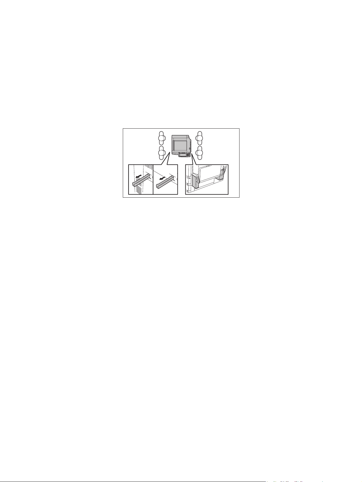
1) Transportation/Installation
- When transporting/installing the equipment, employ four persons and be sure to hold the positions as shown in the figure.
The equipment is quite heavy and weighs approximately 113 kg (249 lb), therefore pay full attention when handling it.
- Be sure not to hold the movable parts or units (e.g. the control panel, ADU or RADF) when transporting the equipment.
- Be sure to use a dedicated outlet with AC 110 V / 13.2 A, 115 V or 127 V / 12 A, 220-240 V or 240
V / 8 A for its power source.
- The equipment must be grounded for safety.
- Select a suitable place for installation. Avoid excessive heat, high humidity, dust, vibration and
direct sunlight.
- Provide proper ventilation since the equipment emits a slight amount of ozone.
- To insure adequate working space for the copying operation, keep a minimum clearance of 80
cm (32”) on the left, 80 cm (32”) on the right and 10 cm (4”) on the rear.
- The equipment shall be installed near the socket outlet and shall be accessible.
- Be sure to fix and plug in the power cable securely after the installation so that no one trips over
it.

2) General Precautions at Service
- Be sure to turn the power OFF and unplug the power cable during service (except for the service
should be done with the power turned ON).
- Unplug the power cable and clean the area around the prongs of the plug and socket outlet once
a year or more. A fire may occur when dust lies on this area.
- When the parts are disassembled, reassembly is the reverse of disassembly unless otherwise
noted in this manual or other related documents. Be careful not to install small parts such as
screws, washers, pins, E-rings, star washers in the wrong places.
- Basically, the equipment should not be operated with any parts removed or disassembled.
- The PC board must be stored in an anti-electrostatic bag and handled carefully using a wristband
since the ICs on it may be damaged due to static electricity.
Caution: Before using the wristband, unplug the power cable of the equipment and
make sure that there are no charged objects which are not insulated in the
vicinity.
- Avoid expose to laser beam during service. This equipment uses a laser diode. Be sure not to
expose your eyes to the laser beam. Do not insert reflecting parts or tools such as a screwdriver
on the laser beam path. Remove all reflecting metals such as watches, rings, etc. before starting
service.
- Be sure not to touch high-temperature sections such as the exposure lamp, fuser unit, damp
heater and areas around them.
- Be sure not to touch high-voltage sections such as the chargers, transfer belt, 2nd transfer roller,
developer, IH control circuit, high-voltage transformer, exposure lamp control inverter, inverter for
the LCD backlight and power supply unit. Especially, the board of these components should not
be touched since the electric charge may remain in the capacitors, etc. on them even after the
power is turned OFF.
- Make sure that the equipment will not operate before touching potentially dangerous places (e.g.
rotating/operating sections such as gears, belts pulleys, fans and laser beam exit of the laser
optical unit).
- Be careful when removing the covers since there might be the parts with very sharp edges
underneath.
- When servicing the equipment with the power turned ON, be sure not to touch live sections and
rotating/operating sections. Avoid exposing your eyes to laser beam.
- Use designated jigs and tools.
- Use recommended measuring instruments or equivalents.
- Return the equipment to the original state and check the operation when the service is finished.
3) Important Service Parts for Safety
- The breaker, door switch, fuse, thermostat, thermofuse, thermistor, IC-RAMs including lithium
batteries, etc. are particularly important for safety. Be sure to handle/install them properly. If
these parts are short-circuited and their functions become ineffective, they may result in fatal
accidents such as burnout. Do not allow a short-circuit or do not use the parts not recommended
by Toshiba TEC Corporation.
4) Cautionary Labels
- During servicing, be sure to check the rating plate and cautionary labels such as “Unplug the
power cable during service”, “CAUTION. HOT”, “CAUTION. HIGH VOLTAGE”, “CAUTION.
LASER BEAM”, etc. to see if there is any dirt on their surface and if they are properly stuck to the
equipment.

5) Disposal of the Equipment, Supplies, Packing Materials, Used Batteries and IC-RAMs
- Regarding the recovery and disposal of the equipment, supplies, packing materials, used batteries and IC-RAMs including lithium batteries, follow the relevant local regulations or rules.
Caution:
Dispose of used batteries and IC-RAMs including lithium batteries according to this manual.
Attention:
Se débarrasser de batteries et IC-RAMs usés y compris les batteries en lithium selon ce manuel.
Vorsicht:
Entsorgung der gebrauchten Batterien und IC-RAMs (inclusive der Lithium-Batterie) nach diesem Handbuch.


CONTENTS
1. SPECIFICATIONS/ACCESSORIES/OPTIONS/SUPPLIES ......................................... 1-1
1.1 Specifications....................................................................................................................... 1-1
1.2 Accessories ......................................................................................................................... 1-7
1.3 Options ................................................................................................................................ 1-8
1.4 Supplies............................................................................................................................... 1-9
1.5 System List ........................................................................................................................ 1-10
2. ERROR CODE AND SELF-DIAGNOSTIC MODE........................................................ 2-1
2.1 Error Code List..................................................................................................................... 2-1
2.1.1 Jam........................................................................................................................... 2-1
2.1.2 Service call ...............................................................................................................2-7
2.1.3 Error in Internet FAX / Scanning Function.............................................................. 2-13
2.1.4 Printer function error............................................................................................... 2-21
2.2 Self-diagnosis Modes ........................................................................................................ 2-23
2.2.1 Input check (Test mode 03).................................................................................... 2-25
2.2.2 Output check (test mode 03) .................................................................................. 2-34
2.2.3 Test print mode (test mode 04) .............................................................................. 2-37
2.2.4 Adjustment mode (05) ............................................................................................ 2-38
2.2.5 Setting mode (08) ................................................................................................... 2-85
2.2.6 Pixel counter......................................................................................................... 2-198
2.2.7 Classification List of Adjustment Mode (05) / Setting Mode (08).......................... 2-208
3. ADJUSTMENT .............................................................................................................. 3-1
3.1 Adjustment Order (Image Related Adjustment)................................................................... 3-1
3.2 Adjustment of the Auto-Toner Sensor ................................................................................. 3-2
3.3 Performing Image Quality Control ....................................................................................... 3-5
3.4 Image Dimensional Adjustment........................................................................................... 3-6
3.4.1 General description .................................................................................................. 3-6
3.4.2 Paper alignment at the registration roller ................................................................. 3-8
3.4.3 Printer related adjustment ........................................................................................ 3-9
3.4.4 Scanner related adjustment ................................................................................... 3-14
3.5 Image Quality Adjustment (Copying Function) .................................................................. 3-21
3.5.1 Automatic gamma adjustment ................................................................................ 3-21
3.5.2 Color Deviation Adjustment .................................................................................... 3-22
3.5.3 Density adjustment ................................................................................................. 3-28
3.5.4 Color balance adjustment....................................................................................... 3-29
3.5.5 Gamma balance adjustment .................................................................................. 3-30
3.5.6 Offsetting adjustment for background processing .................................................. 3-30
3.5.7 Judgment threshold for ACS .................................................................................. 3-31
3.5.8 Sharpness adjustment............................................................................................ 3-31
3.5.9 Setting range correction ......................................................................................... 3-32
3.5.10 Setting range correction (Adjustment of background peak) ................................... 3-32
3.5.11 Adjustment of smudged/faint text ........................................................................... 3-33
3.5.12 Adaptation to highlighter......................................................................................... 3-33
3.5.13 Beam level conversion setting................................................................................ 3-34
3.5.14 Maximum toner density adjustment to paper type.................................................. 3-34
3.5.15 Maximum text density adjustment .......................................................................... 3-35
3.5.16 Text/Photo reproduction level adjustment .............................................................. 3-35
3.5.17 Black reproduction switching at the Twin color copy mode .................................... 3-36
3.5.18 Background adjustment(Black Mode) .................................................................... 3-36
3.6 Image Quality Adjustment (Printing Function) ................................................................... 3-37
3.6.1 Automatic gamma adjustment ................................................................................ 3-37
3.6.2 Color deviation adjustment ..................................................................................... 3-38
June 2005 © TOSHIBA TEC e-STUDIO281c/351c/451c CONTENTS
1

3.6.3 Gamma balance adjustment (Black Mode) ............................................................ 3-38
3.6.4 Color balance adjustment (Color Mode)................................................................. 3-39
3.6.5 Adjustment of smudged/faint text ........................................................................... 3-39
3.6.6 Upper limit value at Toner Saving Mode ................................................................ 3-40
3.6.7 Dot size adjustment in black printing ...................................................................... 3-40
3.6.8 Maximum toner density adjustment to paper type.................................................. 3-40
3.6.9 Image processing: Gamma correction table all clearing......................................... 3-40
3.7 Image Quality Adjustment (Scanning Function) ................................................................ 3-41
3.7.1 Gamma balance adjustment .................................................................................. 3-41
3.7.2 Density adjustment (Black Mode)........................................................................... 3-42
3.7.3 Background adjustment (Gray Scale Mode) .......................................................... 3-43
3.7.4 Background adjustment (Color Mode).................................................................... 3-43
3.7.5 Judgment threshold for ACS .................................................................................. 3-44
3.7.6 Sharpness adjustment............................................................................................ 3-44
3.7.7 Setting range correction ......................................................................................... 3-45
3.7.8 Setting range correction (Adjustment of background peak) ................................... 3-45
3.7.9 Fine adjustment of black density ............................................................................ 3-46
3.7.10 RGB conversion method selection ......................................................................... 3-46
3.7.11 Reproduction ratio of primary scanning direction (black) ....................................... 3-47
3.7.12 Reproduction ratio of primary scanning direction (color) ........................................ 3-47
3.8 High-Voltage Transformer Setting ..................................................................................... 3-48
3.8.1 General description ................................................................................................ 3-48
3.8.2 Setting at the replacement of high-voltage transformer ......................................... 3-48
3.9 Adjustment of the Scanner Section ................................................................................... 3-49
3.9.1 Carriages ................................................................................................................ 3-49
3.9.2 Lens unit................................................................................................................. 3-53
3.10 Adjustment of the Paper Feeding System ......................................................................... 3-55
3.10.1 Sheet sideways deviation caused by paper feeding .............................................. 3-55
3.11 Adjustment of the Developer Unit...................................................................................... 3-57
3.11.1 Doctor-to-sleeve gap (black developer unit)........................................................... 3-57
3.11.2 Doctor-to-sleeve gap (color developer unit) ........................................................... 3-59
3.11.3 Black developer unit lift up/down timing adjustment............................................... 3-61
3.12 Adjustment of the RADF (MR-3018).................................................................................. 3-63
3.12.1 Adjustment of RADF Position ................................................................................. 3-63
3.12.2 Adjustment of RADF Height ................................................................................... 3-68
3.12.3 Adjustment of Skew................................................................................................ 3-70
3.12.4 Adjustment of the Leading Edge Position .............................................................. 3-73
3.12.5 Adjustment of Horizontal Position .......................................................................... 3-74
3.12.6 Adjustment of Copy Ratio....................................................................................... 3-76
3.12.7 Adjustment of RADF Opening/Closing Sensor....................................................... 3-77
3.13 Adjustment of the Finisher (MJ-1022)................................................................................ 3-78
3.13.1 Adjusting the jogging plate width ............................................................................ 3-78
3.13.2 Adjusting the angle of the jogging plate ................................................................. 3-80
3.13.3 Adjusting the overlap of the sensor flag ................................................................. 3-81
3.13.4 Adjusting the tension of the stack processing motor belt ....................................... 3-82
3.13.5 Releasing the stack tray guide lever fixing plate .................................................... 3-84
3.13.6 Adjustment of the upper tray angle ........................................................................ 3-85
3.13.7 DIP switch functions ............................................................................................... 3-87
3.14 Adjustment of the Finisher (MJ-1023/1024)....................................................................... 3-89
3.14.1 Adjusting the alignment position (Finisher unit)...................................................... 3-89
3.14.2 Adjusting the staple position (Finisher unit)............................................................ 3-90
3.14.3 Adjusting the folding position (Saddle stitcher unit)................................................ 3-91
3.14.4 Fine adjustment of binding/folding position (Saddle stitcher unit) .......................... 3-94
3.14.5 Sensor output adjustment (Puncher unit)............................................................... 3-94
3.14.6 Registering the number of punch holes (Puncher unit) .......................................... 3-95
e-STUDIO281c/351c/451c CONTENTS June 2005 © TOSHIBA TEC
2

4. PREVENTIVE MAINTENANCE (PM)............................................................................ 4-1
4.1 PM Support Mode................................................................................................................ 4-1
4.1.1 General description .................................................................................................. 4-1
4.1.2 Operational flow and operational screen .................................................................. 4-1
4.1.3 Work flow of parts replacement ................................................................................ 4-8
4.2 General Descriptions for PM Procedure.............................................................................. 4-9
4.3 Operational Items in Overhauling ...................................................................................... 4-10
4.4 Preventive Maintenance Checklist..................................................................................... 4-11
4.5 PM KIT............................................................................................................................... 4-28
4.6 Jig List ............................................................................................................................... 4-29
4.7 Grease List ........................................................................................................................ 4-30
4.8 Precautions for Storing and Handling Supplies ................................................................. 4-31
4.8.1 Precautions for storing TOSHIBA supplies ............................................................ 4-31
4.8.2 Checking and cleaning of photoconductive drum................................................... 4-31
4.8.3 Checking and cleaning of drum cleaning blade and transfer belt cleaning blade... 4-32
4.8.4 Handling of drum cleaner brush ............................................................................. 4-32
4.8.5 Handling of transfer belt ......................................................................................... 4-32
4.8.6 Checking and cleaning of fuser belt and pressure roller ........................................ 4-33
4.8.7 Checking and replacing the oil roller and cleaning roller ........................................ 4-33
4.8.8 Checking and cleaning of discharge brush ............................................................ 4-34
5. TROUBLESHOOTING .................................................................................................. 5-1
5.1 Diagnosis and Prescription for Each Error Code ................................................................. 5-1
5.1.1 Paper transport jam (paper exit section) .................................................................. 5-1
5.1.2 Paper misfeeding ..................................................................................................... 5-3
5.1.3 Paper transport jam ................................................................................................ 5-10
5.1.4 Other paper jam ..................................................................................................... 5-18
5.1.5 Cover open jam ...................................................................................................... 5-20
5.1.6 RADF jam ............................................................................................................... 5-24
5.1.7 Finisher jam ............................................................................................................ 5-29
5.1.8 Drive system related service call ............................................................................ 5-43
5.1.9 Paper feeding system related service call .............................................................. 5-44
5.1.10 Scanning system related service call ..................................................................... 5-50
5.1.11 Fuser unit related service call................................................................................. 5-51
5.1.12 Communication related service call........................................................................ 5-54
5.1.13 RADF related service call ....................................................................................... 5-55
5.1.14 Circuit related service call ...................................................................................... 5-55
5.1.15 Laser optical unit related service call ..................................................................... 5-57
5.1.16 Finisher related service call .................................................................................... 5-58
5.1.17 Image control related service call........................................................................... 5-69
5.1.18 Copy process related service call........................................................................... 5-72
5.1.19 Toner density control related service call ............................................................... 5-76
5.1.20 Other service call.................................................................................................... 5-80
5.1.21 Error in Internet FAX / Scanning Function.............................................................. 5-81
5.2 Troubleshooting for the Image........................................................................................... 5-95
5.3 Replacement of PC Boards and HDD ............................................................................. 5-127
5.3.1 Replacing HDD..................................................................................................... 5-127
5.3.2 Replacing SYS board ........................................................................................... 5-129
5.3.3 Replacing SLG board ........................................................................................... 5-130
5.3.4 Replacing or clearing NVRAM.............................................................................. 5-130
5.3.5 Cautions when Data overwrite kit (GP-1060) is installed .................................... 5-131
5.3.6 HDD information display....................................................................................... 5-132
5.4 Other errors ..................................................................................................................... 5-134
6. FIRMWARE UPDATING ............................................................................................... 6-1
6.1 Firmware Updating with Download Jig ................................................................................ 6-2
June 2005 © TOSHIBA TEC e-STUDIO281c/351c/451c CONTENTS
3

6.1.1 PWA-DWNLD-350-JIG2 (48 MB) ............................................................................. 6-4
6.1.2 Writing the data to the download jig (PWA-DWNLD-350-JIG) ............................... 6-13
6.1.3 K-PWA-DLM-320.................................................................................................... 6-15
6.2 Firmware Updating with USB Storage Device................................................................... 6-26
6.2.1 Appendix ................................................................................................................ 6-41
7. POWER SUPPLY UNIT ................................................................................................ 7-1
7.1 Output Channel ................................................................................................................... 7-1
7.2 Fuse..................................................................................................................................... 7-3
7.3 Configuration of Power Supply Unit..................................................................................... 7-4
8. REMOTE SERVICE....................................................................................................... 8-1
8.1 Auto Supply Order ............................................................................................................... 8-1
8.1.1 Outline ...................................................................................................................... 8-1
8.1.2 Setting Item .............................................................................................................. 8-2
8.1.3 Setting procedure ..................................................................................................... 8-4
8.1.4 Order Sheet Format ............................................................................................... 8-11
8.2 Service Notification............................................................................................................ 8-13
8.2.1 Outline ....................................................................................................................8-13
8.2.2 Setting ....................................................................................................................8-13
8.2.3 Items to be notified ................................................................................................. 8-19
9. DATA CLONING with USB STORAGE DEVICE ......................................................... 9-1
10. WIRE HARNESS CONNECTION DIAGRAMS ........................................................... 10-1
10.1 AC Wire Harness ............................................................................................................... 10-1
10.2 DC Wire Harness ....................................................................................................... Appendix
10.3 Electric Parts Layout.................................................................................................. Appendix
e-STUDIO281c/351c/451c CONTENTS June 2005 © TOSHIBA TEC
4
05/11

1. SPECIFICATIONS/ACCESSORIES/OPTIONS/
SUPPLIES
2. ERROR CODE AND SELF-DIAGNOSTIC
MODE
3. ADJUSTMENT
4. PREVENTIVE MAINTENANCE (PM)
5. TROUBLESHOOTING
1
2
3
4
5
6. FIRMWARE UPDATING
7. POWER SUPPLY UNIT
8. REMOTE SERVICE
9. DATA CLONING with USB STORAGE DEVICE
10. WIRE HARNESS CONNECTION DIAGRAMS
6
7
8
9
10
05/11

1. SPECIFICATIONS/ACCESSORIES/OPTIONS/SUPPLIES
1.1 Specifications
yCopy process .......................... Indirect electrophotographic process (dry)
yType......................................... Desktop type (Console type: when optional Paper Feed Pedestal
(PFP) or optional Large Capacity Feeder (LCF) is installed.)
yOriginal table ........................... Fixed type (the left rear corner used as guide to place originals)
yAccepted originals ................... Original type: Sheets, books and 3-dimensional objects
Note that when the optional Reversing Automatic Document Feeder is
used, carbon, bounded or stapled originals cannot be accepted, and
paper type of the original should be 35-157g/m
Cover) for single-sided copy and 50-157 g/m
Cover) for double-sided copy.
Maximum size: A3/LD
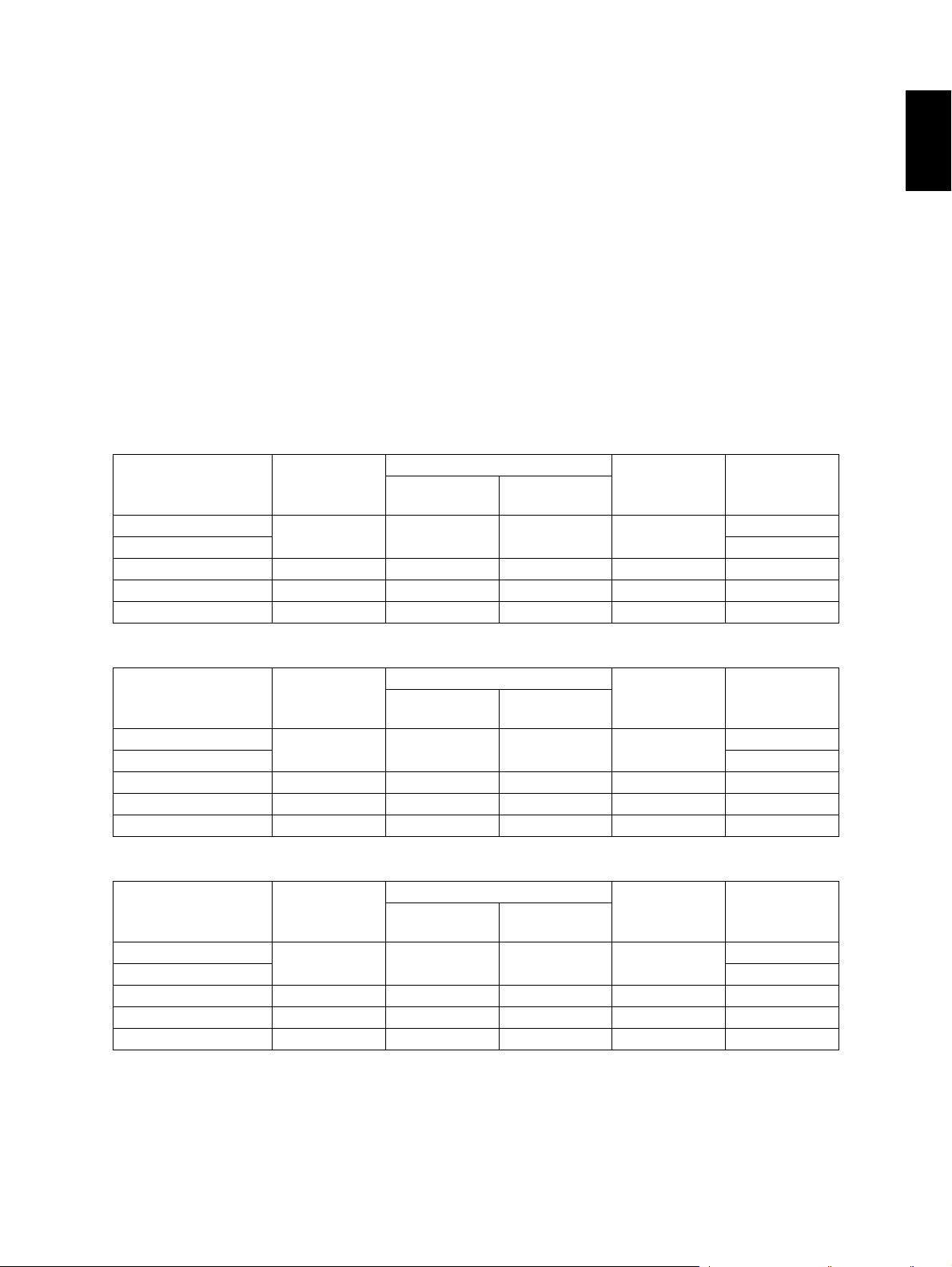
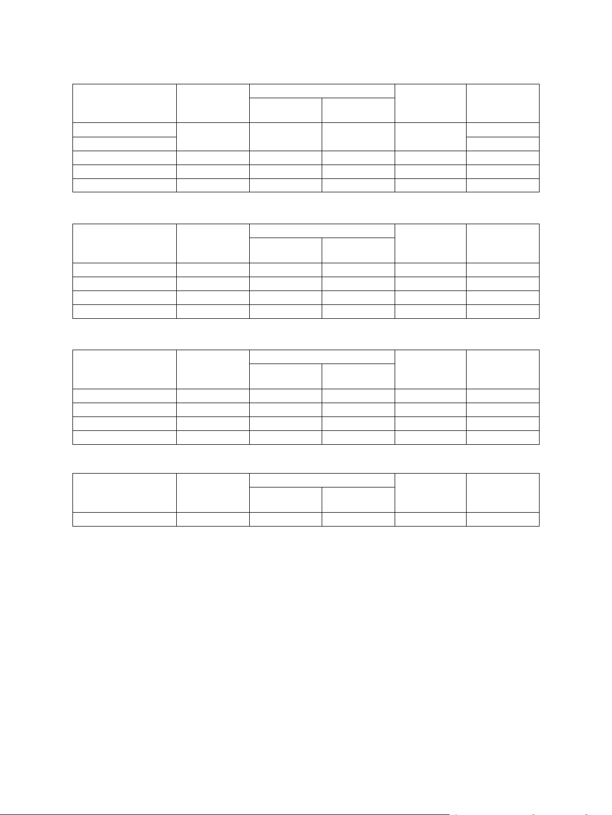
• Copy speed (Copies/min.)
e-STUDIO281c
Paper supply
Paper size
A4, LT 28 (11) 28 (11) 16 (5) 28 (11) 28 (11)
B5, A5-R, ST-R -
A4-R, B5-R, LT-R 21 (5) 21 (5) 16 (5) 21 (5) -
B4, LG 18 (5) 18 (5) 16 (5) 18 (5) -
A3, LD 16 (5) 16 (5) 16 (5) 16 (5) -
Drawer
Size specified
Bypass feed
Size not
specified
2
(9.3 lb. Bond -58 lb.
2
(13.3 lb. Bond -58 lb.
PFP
LCF
(A4/LT only)
1
e-STUDIO351c
Paper supply
Paper size
A4, LT 35 (11) 35 (11) 21 (5) 35 (11) 35 (11)
B5, A5-R, ST-R -
A4-R, B5-R, LT-R 28 (5) 28 (5) 21 (5) 28 (5) -
B4, LG 24 (5) 24 (5) 21 (5) 24 (5) -
A3, LD 21 (5) 21 (5) 21 (5) 21 (5) -
Drawer
Size specified
Bypass feed
Size not
specified
PFP
LCF
(A4/LT only)
e-STUDIO451c
Paper supply
Paper size
A4, LT 45 (11) 45 (11) 22 (5) 45 (11) 45 (11)
B5, A5-R, ST-R -
A4-R, B5-R, LT-R 32 (5) 32 (5) 22 (5) 32 (5) -
B4, LG 26 (5) 26 (5) 22 (5) 26 (5) -
A3, LD 22 (5) 22 (5) 22 (5) 22 (5) -
Drawer
Size specified
Bypass feed
Size not
specified
PFP
LCF
(A4/LT only)
* "-" means "Not acceptable".
* When originals are manually placed for single-sided, continuous copying.
* Plain paper is selected for the paper type.
* When the Reversing Automatic Document Feeder is used, copying in the speed of 28, 35 and 45
sheets per minute are only possible under the following conditions:
June 2005 © TOSHIBA TEC e-STUDIO281c/351c/451c SPECIFICATIONS/ACCESSORIES/OPTIONS/SUPPLIES
1 - 1
• Original: A4 or LT (single-sided)
• Mode: APS and Automatic density not selected, Plain paper mode
• Number of copies:
Black mode: 28 sheets or more (e-STUDIO281c), 35 sheets or more (e-STUDIO351c), 45 sheets
or more (e-STUDIO451c)
Color mode: 11 sheets or more
• Reproduction ratio: 100%
* The values in ( ) can be realized in the color mode.
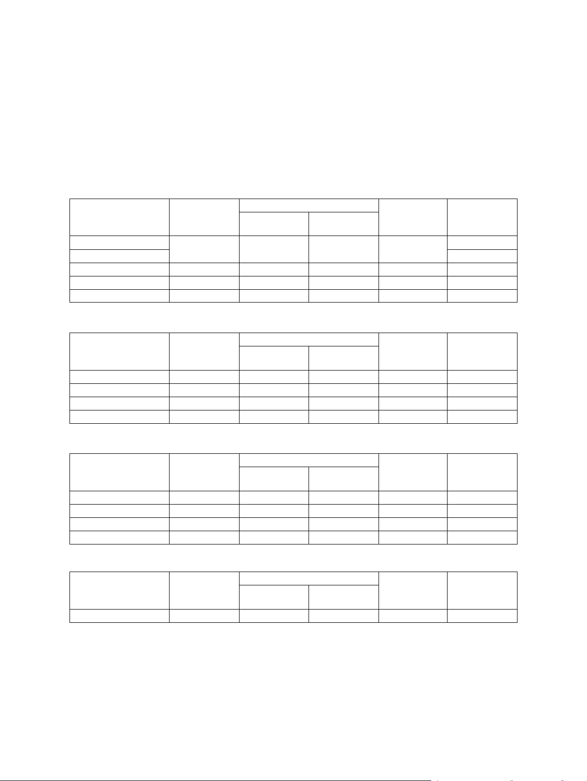
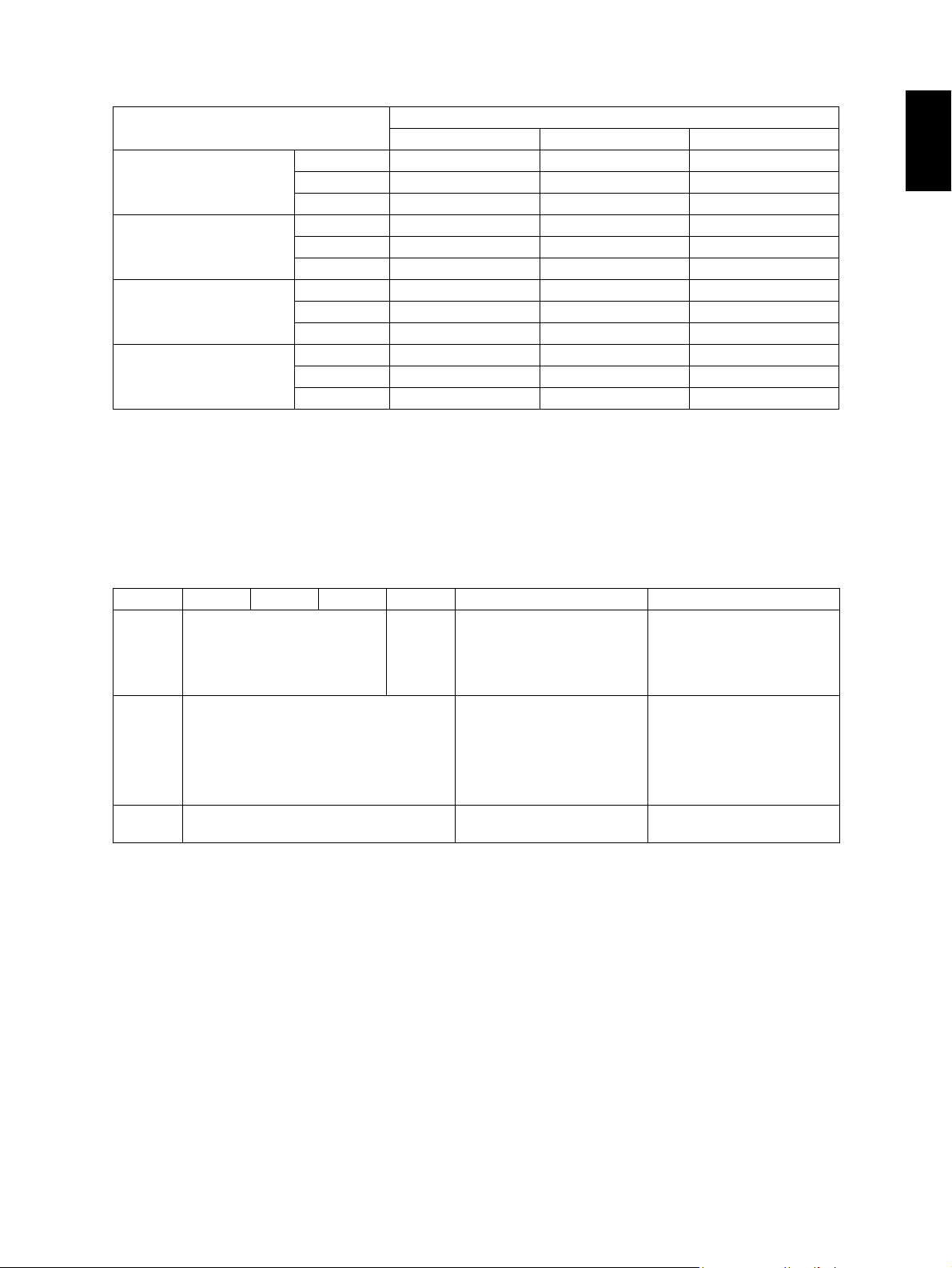
Thick paper / OHP
e-STUDIO281c
Thick1 (81 g/m
Paper size
A4, LT 28 (11) 28 (11) 16 (5) 28 (11) 28 (11)
B5, A5-R, ST-R -
A4-R, B5-R, LT-R 20 (5) 20 (5) 16 (5) 20 (5) -
B4, LG 18 (5) 18 (5) 16 (5) 18 (5) -
A3, LD 16 (5) 16 (5) 16 (5) 16 (5) -
Thick2 (106 g/m
Paper size
A4, LT, B5, A5-R, ST-R - 20 (6) 10 (2) - -
A4-R, B5-R, LT-R - 14 (3) 10 (2) - -
B4, LG - 11 (3) 10 (2) - -
A3, LD - 10 (2) 10 (2) - -
2
to 105 g/m2, 21 lb. Bond to 28 lb. Bond)
Paper supply
2
to 163 g/m2, 29 lb. Bond to 90 lb. Index)
Paper supply
Drawer
Drawer
Bypass feed
Size specified
Bypass feed
Size specified
Size not
specified
Size not
specified
PFP
PFP
LCF
(A4/LT only)
LCF
(A4/LT only)
2
Thick3 (164 g/m
Paper supply
Paper size
A4, LT, B5, A5-R, ST-R - 20 (2) 10 (2) - -
A4-R, B5-R, LT-R - 14 (2) 10 (2) - -
B4, LG - 11 (2) 10 (2) - -
A3, LD - 10 (2) 10 (2) - -
to 209 g/m2, 91 lb. Index to 110 lb. Index)
Bypass feed
Drawer
Size specified
Size not
specified
PFP
LCF
(A4/LT only)
OHP
Paper supply
Paper size
A4, LT - 10 (3) - - -
e-STUDIO281c/351c/451c SPECIFICATIONS/ACCESSORIES/OPTIONS/SUPPLIES June 2005 © TOSHIBA TEC
Drawer
Size specified
Bypass feed
Size not
specified
1 - 2
PFP
LCF
(A4/LT only)
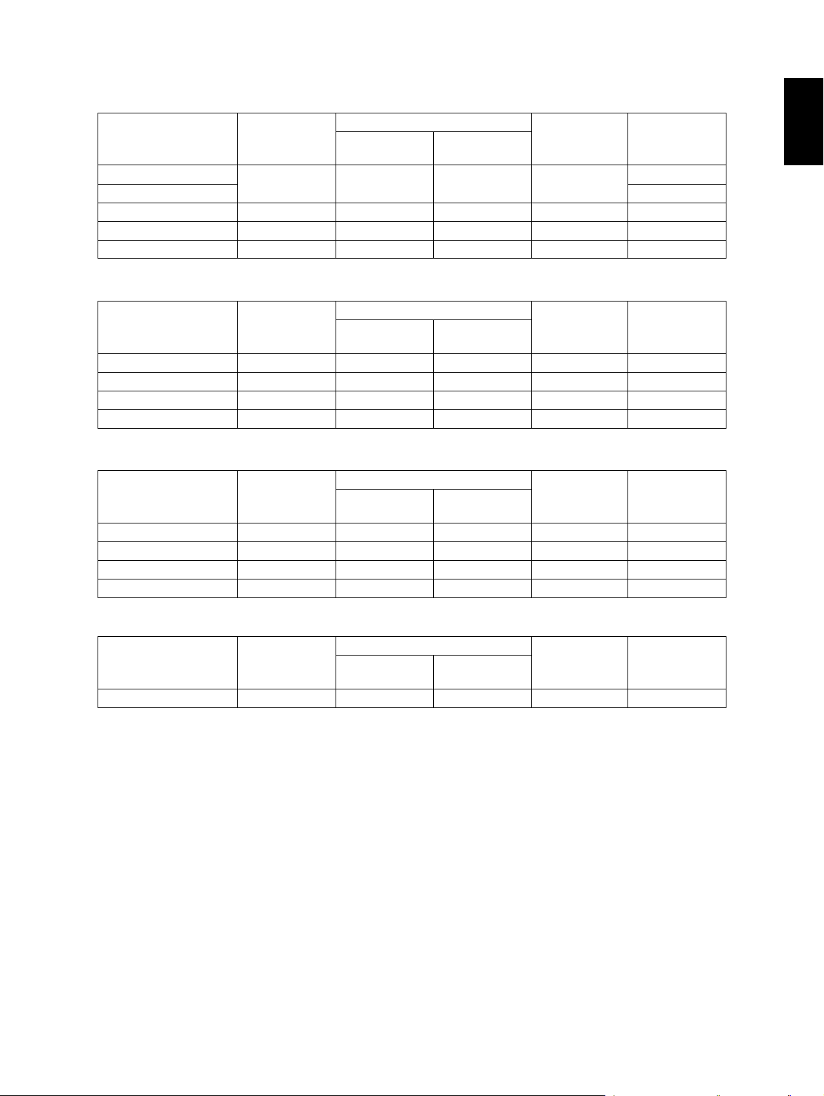
e-STUDIO351c
2
Thick1 (81 g/m
Paper supply
Paper size
A4, LT 30 (11) 30 (11) 16 (5) 30 (11) 30 (11)
B5, A5-R, ST-R -
A4-R, B5-R, LT-R 23 (5) 23 (5) 16 (5) 23 (5) -
B4, LG 19 (5) 19 (5) 16 (5) 19 (5) -
A3, LD 16 (5) 16 (5) 16 (5) 16 (5) -
Thick2 (106 g/m
Paper supply
Paper size
A4, LT, B5, A5-R, ST-R - 20 (6) 10 (2) - -
A4-R, B5-R, LT-R - 14 (3) 10 (2) - -
B4, LG - 11 (3) 10 (2) - -
A3, LD - 10 (2) 10 (2) - -
Thick3 (164 g/m
Paper supply
Paper size
A4, LT, B5, A5-R, ST-R - 20 (2) 10 (2) - -
A4-R, B5-R, LT-R - 14 (2) 10 (2) - -
B4, LG - 11 (2) 10 (2) - -
A3, LD - 10 (2) 10 (2) - -
to 105 g/m2, 21 lb. Bond to 28 lb. Bond)
Bypass feed
Drawer
2
to 163 g/m2, 29 lb. Bond to 90 lb. Index)
Drawer
2
to 209 g/m2, 91 lb. Index to 110 lb. Index)
Drawer
Size specified
Bypass feed
Size specified
Bypass feed
Size specified
Size not
specified
Size not
specified
Size not
specified
PFP
PFP
PFP
LCF
(A4/LT only)
LCF
(A4/LT only)
LCF
(A4/LT only)
1
OHP
Paper supply
Paper size
A4, LT - 10 (3) - - -
June 2005 © TOSHIBA TEC e-STUDIO281c/351c/451c SPECIFICATIONS/ACCESSORIES/OPTIONS/SUPPLIES
Drawer
Size specified
Bypass feed
Size not
specified
1 - 3
PFP
LCF
(A4/LT only)
e-STUDIO451c
2
Thick1 (81 g/m
Paper supply
Paper size
A4, LT 30 (11) 30 (11) 16 (5) 30 (11) 30 (11)
B5, A5-R, ST-R -
A4-R, B5-R, LT-R 23 (5) 23 (5) 16 (5) 23 (5) -
B4, LG 19 (5) 19 (5) 16 (5) 19 (5) -
A3, LD 16 (5) 16 (5) 16 (5) 16 (5) -
Thick2 (106 g/m
Paper supply
Paper size
A4, LT, B5, A5-R, ST-R - 20 (6) 10 (2) - -
A4-R, B5-R, LT-R - 14 (3) 10 (2) - -
B4, LG - 11 (3) 10 (2) - -
A3, LD - 10 (2) 10 (2) - -
Thick3 (164 g/m
Paper supply
Paper size
A4, LT, B5, A5-R, ST-R - 20 (2) 10 (2) - -
A4-R, B5-R, LT-R - 14 (2) 10 (2) - -
B4, LG - 11 (2) 10 (2) - -
A3, LD - 10 (2) 10 (2) - -
to 105 g/m2, 21 lb. Bond to 28 lb. Bond)
Bypass feed
Drawer
2
to 163 g/m2, 29 lb. Bond to 90 lb. Index)
Drawer
2
to 209 g/m2, 91 lb. Index to 110 lb. Index)
Drawer
Size specified
Bypass feed
Size specified
Bypass feed
Size specified
Size not
specified
Size not
specified
Size not
specified
PFP
PFP
PFP
LCF
(A4/LT only)
LCF
(A4/LT only)
LCF
(A4/LT only)
OHP
Paper supply
Paper size
A4, LT - 10 (3) - - -
Drawer
Size specified
Bypass feed
Size not
specified
PFP
LCF
(A4/LT only)
* "-" means "Not acceptable".
* When originals are manually placed for single side, continuous copying.
* The bypass copying speed is measured with the paper size specified.
* The values in ( ) can be realized in the color mode.
e-STUDIO281c/351c/451c SPECIFICATIONS/ACCESSORIES/OPTIONS/SUPPLIES June 2005 © TOSHIBA TEC
1 - 4
* System copy speed
Copy mode
Single-sided originals
↓
Single-sided copies
Single-sided originals
↓
Double-sided copies
Double-sided originals
↓
Double-sided copies
Double-sided originals
↓
Single-sided copies
e-STUDIO281c e-STUDIO351c e-STUDIO451c
1 set 31.26 (71.97) 28.15 (71.97) 24.99 (71.97)
3 sets 74.07 (182.19) 61.02 (182.19) 50.03 (182.19)
5 sets 116.64 (289.94) 95.19 (289.94) 76.63 (289.94)
1 set 32.61 (81.63) 29.65 (81.63) 28.49 (81.63)
3 sets 74.69 (189.38) 64.92 (189.38) 60.76 (189.38)
5 sets 117.45 (299.04) 101.75 (299.04) 92.2 (299.04)
1 set 64.24 (138.12) 63.54 (138.12) 63.01 (138.12)
3 sets 150.73 (355.91) 134.25 (355.91) 126.36 (355.91)
5 sets 234.59 (574.51) 205.69 (574.51) 189.67 (574.51)
1 set 58.85 (128.31) 58.76 (128.31) 58.09 (128.31)
3 sets 143.68 (347.08) 126.57 (347.08) 110.94 (347.08)
5 sets 228.58 (565.02) 194.49 (565.02) 165.19 (565.02)
Sec.
* Shows the period of time from when the [START] button is pressed until the message "Ready" is dis-
played. (10 sheets of A4/LT size original are set on the RADF and one of the copy modes above is
selected.)
* Setting: when in the Text/Photo mode with Automatic density and APS/AMS set to OFF, or when in
the sort mode with paper fed from the upper drawer.
* The Saddle Stitch Finisher and hole punch unit not installed.
* The values in ( ) are the speeds of when in the color mode.
1
• Copy paper
Drawer ADU PFP LCF Bypass copy Remarks
Size
Weight
Special
paper
A3 to A5-R,
LD to ST-R,
13" LG,
8.5"SQ
64 to 105 g/m
17 to 28 lb.
Bond
A4, LT
2
-
A3 to A6-R, LD to ST-R, 13"
LG, 8.5"SQ, 305 x 457 mm
(Non-standard or userspec-
64 to 209 g/m
64 to 209 g/m2, 17 lb. Bond
(thickness: 80µm or thicker)
(12" x 18")
ified sizes can be set.)
2
, 17 lb. Bond
to 110 lb. Index
(Continuous feeding)
to 110 lb. Index
(Single paper feeding)
Labels, OHP film
Special paper recom-
mended by Toshiba Tec
yFirst copy time ......................... Approx. 6.8 sec. or less (black), approx. 16.2 sec. or less (color)
(A4/LT, upper drawer, 100%, original placed manually)
yWarming-up time ..................... Approx. 40 sec. (Stand-alone, temperature: 20°C)
yMultiple copying....................... Up to 999 copies; Key in set numbers
yReproduction ratio ................... Actual ratio: 100±0.5%
Zooming: 25 to 400% in increments of 1%
(25 to 200% when using RADF)
yResolution/Gradation............... Scanning: 600 dpi x 600 dpi
Printing: Equivalent to 2400 dpi x 600 dpi (black)
Equivalent to 600 dpi x 600 dpi (color)
June 2005 © TOSHIBA TEC e-STUDIO281c/351c/451c SPECIFICATIONS/ACCESSORIES/OPTIONS/SUPPLIES
1 - 5
yEliminated portion.................... Leading edges: 3.0±2.0 mm, Side/trailing edges: 2.0±2.0 mm (black
copy)
Leading edges: 5.0±2.0 mm, Side/trailing edges: 2.0±2.0 mm (color
copy)
Leading / trailing edges: 5.0±2.0 mm, Side edges: 5.0±2.0 mm (black /
color print)
yPaper feeding .......................... Standard drawers:
2 drawers (stack height 60.5 mm, equivalent to 550 sheets; 64 to 80 g/
2
m
(17 to 22 lb. Bond))
PFP:
Option (One drawer or two: stack height 60.5 mm, equivalent to 550
sheets; 64 to 80 g/m
2
(17 to 22 lb. Bond))
LCF:
Option (Stack height 137.5 mm x 2: equivalent to 2500 sheets; 64 to 80
2
g/m
(17 to 22 lb. Bond))
Bypass feeding:
Stack height 11 mm: equivalent to 100 sheets; 64 to 80 g/m
2
(17 to 22
lb. Bond)
yCapacity of originals in the reversing automatic document feeder (Option)
.................................................. A3 to A5-R, LD to ST-R:
100 sheets / 80 g/m
2
(Stack height 16 mm or less)
yAutomatic duplexing unit ......... Stackless, Switchback type
yToner supply............................ Automatic toner density detection/supply
Toner cartridge replacing method
yDensity control......................... Automatic density mode and manual density mode selectable in 11
steps
yWeight ..................................... Approximately 113 kg (249 lb.)
yPower requirements ................ AC 110 V / 13.2 A, 115 V or 127 V / 12 A
220-240 V or 240 V / 8 A (50/60 Hz)
* The acceptable value of each voltage is ±10%.
yPower consumption................. 1.5 kW or less (100 V series), 17 kW or less (200 V series)
* The electric power is supplied to the RADF, Finisher, PFP and LCF through the equipment.
yTotal counter............................ Electronical counter
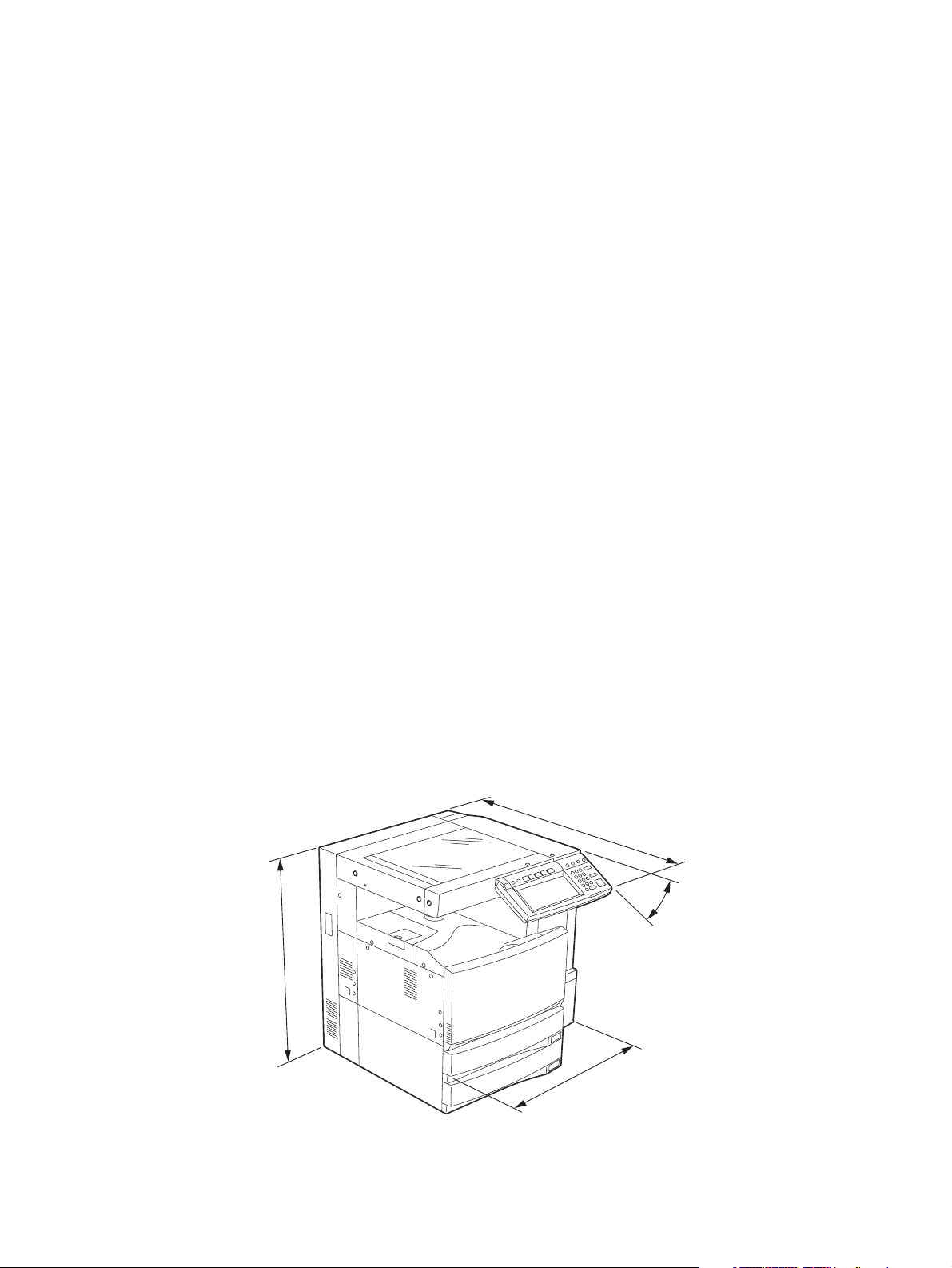
yDimensions of the equipment...................... See the figure below (W 660 x D 758 x H 739 (mm))
* When the tilt angle of the control panel is 45 degrees.
758
45°
739
660
Fig.1-1
e-STUDIO281c/351c/451c SPECIFICATIONS/ACCESSORIES/OPTIONS/SUPPLIES June 2005 © TOSHIBA TEC
1 - 6
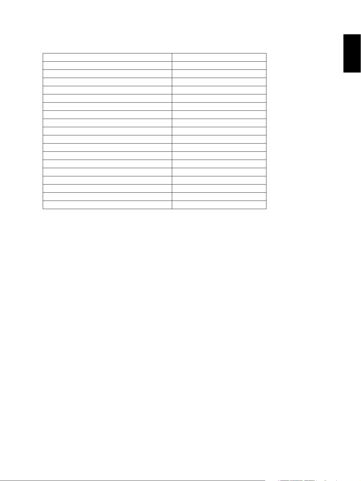
1.2 Accessories
Unpacking/Setup instruction 1 set
Operator’s manual 4 pcs. (except for MJD and ASU)
Operator's manual pocket 1 pc.
Power cable 1 pc.
Warranty sheet 1 pc. (for NAD)
Setup report 1 set (for NAD, MJD and CND)
PM sticker 1 pc. (for MJD)
Drum (installed inside of the equipment) 1 pc.
Control panel stopper 1 pc.
Color developer holder 6 pc.
Rubber plug 4 pcs.
Blind seal (small / large) 3 pcs. /1 pc.
CD-ROM 3 pcs.
Developer material (Y, M, C, K) 1 pc. each (for CND)
Screw M4 x 8 1 pc.
Guide 1 pc.
Approval sheet 1 set (for CND)
Toner cartridge (Y, M, C, K) 1 pc. each (for CND)
Platen cover 1 pc. (for CND)
* Machine version
NAD: North America
MJD: Europe
AUD: Australia
ASD: Asia, Argentine
TWD: Taiwan
SAD Saudi Arabia
ASU Saudi Arabia, Asia
CND China
KRD Korea
JPD: Japan
1
June 2005 © TOSHIBA TEC e-STUDIO281c/351c/451c SPECIFICATIONS/ACCESSORIES/OPTIONS/SUPPLIES
1 - 7
1.3 Options
Platen cover KA-3511PC / -C
Reversing Automatic Document Feeder (RADF) MR-3018
Drawer module MY-1021 / -C
Paper Feed Pedestal (PFP) KD-1011 / -C
Large Capacity Feeder (LCF) KD-1012 A4/LT / A4-C
Hanging Finisher MJ-1022 / -C
Finisher MJ-1023 / -C
Saddle Stitch Finisher MJ-1024 / -C
Hole punch unit MJ-6004 N/E/F/S / E-C
Staple cartridge STAPLE-1600 (for MJ-1022)
STAPLE-2000 (for MJ-1023/1024)
STAPLE-600
(for saddle stitcher of MJ-1024)
Bridge kit KN-3511 / -C
Work table KK-3511 / -C
Damp heater kit MF-3511U/E
FAX unit GD-1200 NA/AU/AS/EU/C/TW
2nd line for fax unit GD-1160 NA/EU-N/C/TW
128 MB Expansion memory GC-1181
512 MB Expansion memory GC-1230
Wireless LAN module GN-1040/1041
PCI slot GO-1060
Scrambler board GP-1040
Bluetooth module GN-2010
Antenna GN-3010
Parallel interface kit GF-1140
Data overwrite kit GP-1060
Desk MH-1700
Harness kit for coin controller GQ-1020
Notes:
1. The bridge kit (KN-3511) is necessary for installation of the finisher (MJ-1022, MJ-1023 or MJ-
1024).
2. The finisher (MJ-1023 or MJ-1024) is necessary for installation of the hole punch unit (MJ6004N/E/F/S).
3. The PCI slot (GO-1060) is necessary for the installation of the scrambler board (GP-1040)
and the parallel interface kit (GF-1140).
4. The antenna (GN-3010) is necessary to enable the wireless LAN module (GN-1040/1041)
and the bluetooth module (GN-2010).
5. Up to 1 antenna (GN-3010) can be connected to the wireless LAN module (GN-1040/1041).
6. When the wireless LAN module (GN-1040/1041) and the bluetooth module (GN-2010) are
installed together, only 1 antenna (GN-3010) can be connected to each.
e-STUDIO281c/351c/451c SPECIFICATIONS/ACCESSORIES/OPTIONS/SUPPLIES June 2005 © TOSHIBA TEC
1 - 8
05/11
1.4 Supplies
Drum OD-3511N
Toner bag PS-TB-281C/ C-E/ C-C
Developer (K) D-3511-K
Developer (Y) D-281C-Y
Developer (M) D-281C-M
Developer (C) D-281C-C
Toner cartridge (K) PS-ZT281C-K(4) NAD
PS-ZT281C-EK(1) MJD
PS-ZT3511DK Others
PS-ZT3511TK TWD
PS-ZT3511CK CND
Toner cartridge (Y) PS-ZT281C-Y(4) NAD
PS-ZT281C-EY(1) MJD
PS-ZT3511DY Others
PS-ZT3511TY TWD
PS-ZT3511CY CND
Toner cartridge (M) PS-ZT281C-M(4) NAD
PS-ZT281C-EM(1) MJD
PS-ZT3511DM Others
PS-ZT3511TM TWD
PS-ZT3511CM CND
Toner cartridge (C) PS-ZT281C-C(4) NAD
PS-ZT281C-EC(1) MJD
PS-ZT3511DC Others
PS-ZT3511TC TWD
PS-ZT3511CC CND
1
June 2005 © TOSHIBA TEC e-STUDIO281c/351c/451c SPECIFICATIONS/ACCESSORIES/OPTIONS/SUPPLIES
1 - 9
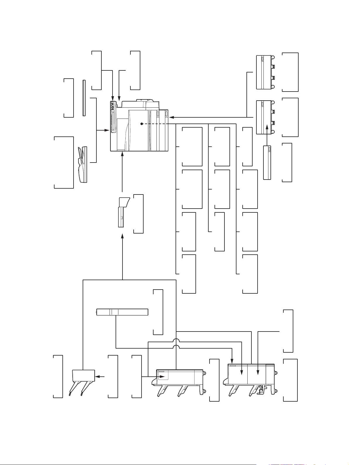
1.5 System List
KK-3511
Work Tray
KA-3511PC
Platen Cover
MF-3511U/E
Damp Heater
Feeder (LCF)
Large Capacity
KD-1012 A4/LT
KD-1011
Paper Feed
Pedestal (PFP)
)
RADF
(
MR-3018
Document Feeder
Reversing Automatic
KN-3511
Bridge Kit
FAX unit
GD-1200
EU/C/TW
NA/AU/AS/
FAX unit
GD-1160
2nd Line for
NA/EU-N/C/TW
memory
GC-1181
Expansion
memory
GC-1230
Expansion
module
Wireless LAN
GN-1040/1041
module
GN-2010
Bluetooth
Antenna
GN-3010
PCI slot
GO-1060
board
GP-1040
Scrambler
Parallel
GF-1140
interface kit
Data
GP-1060
overwrite kit
MY-1021
Drawer Module
Hole Punch Unit
MJ-6004 N/E/F/S
STAPLE-600
Staple Cartridge
MJ-1022
Hanging Finisher
STAPLE-1600
Staple Cartridge
Staple Cartridge
STAPLE-2000
Finisher
MJ-1023
Finisher
MJ-1024
Saddle stitch
Fig.1-2
e-STUDIO281c/351c/451c SPECIFICATIONS/ACCESSORIES/OPTIONS/SUPPLIES June 2005 © TOSHIBA TEC
1 - 10
05/11
2. ERROR CODE AND SELF-DIAGNOSTIC MODE
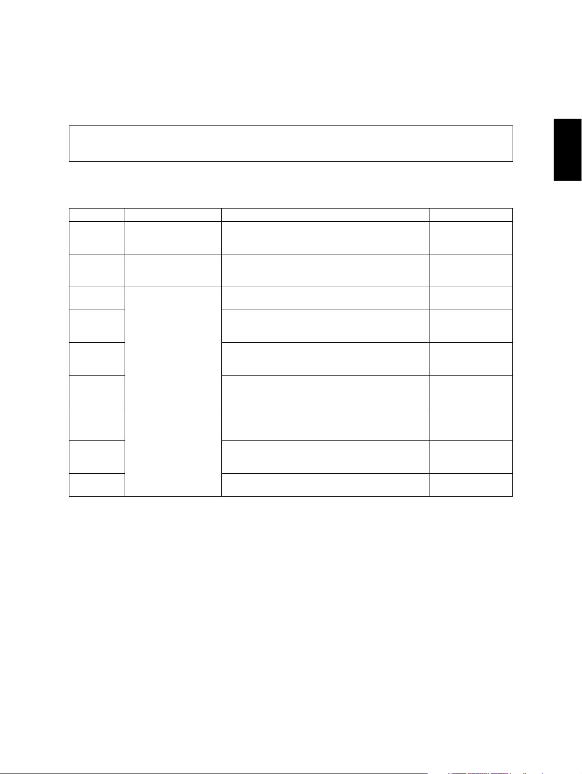
2.1 Error Code List
The following error codes is displayed at the upper right of the screen when the “CLEAR PAPER” or “CALL
SERVICE” symbol is blinking.
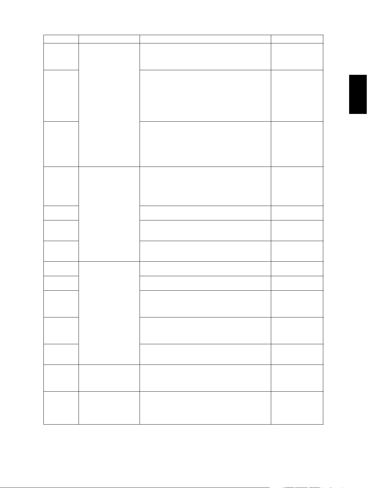
2.1.1 Jam
Error code Classification Contents Troubleshooting
E010 Paper exit jam Jam not reaching the exit sensor : The paper which
has passed through the fuser unit does not reach
the exit sensor.
E020 Paper exit jam Stop jam at the exit sensor: The trailing edge of the
paper does not pass the exit sensor after its leading
edge has reached this sensor.
E030 Other paper jam Power-ON jam: The paper is remaining on the
paper transport path when power is turned ON.
E061 Incorrect paper size setting for upper drawer: The
size of paper in the 1st drawer differs from size setting of the equipment.
E062 Incorrect paper size setting for lower drawer: The
size of paper in the 2nd drawer differs from size setting of the equipment.
E063 Incorrect paper size setting for PFP upper drawer:
The size of paper in the 3rd drawer differs from size
setting of the equipment.
E064 Incorrect paper size setting for PFP lower drawer:
The size of paper in the 4th drawer differs from size
setting of the equipment.
E065 Incorrect paper size setting for bypass tray: The
size of paper in the bypass tray differs from size
setting of the equipment.
E090 Image data delay jam: Image data to be printed
cannot be prepared.
Ch.5.1.1
Ch.5.1.1
Ch.5.1.4
Ch.5.1.4
Ch.5.1.4
Ch.5.1.4
Ch.5.1.4
Ch.5.1.4
Ch.5.1.4
2
June 2005 © TOSHIBA TEC e-STUDIO281c/351c/451c ERROR CODE AND SELF-DIAGNOSTIC MODE
2 - 1

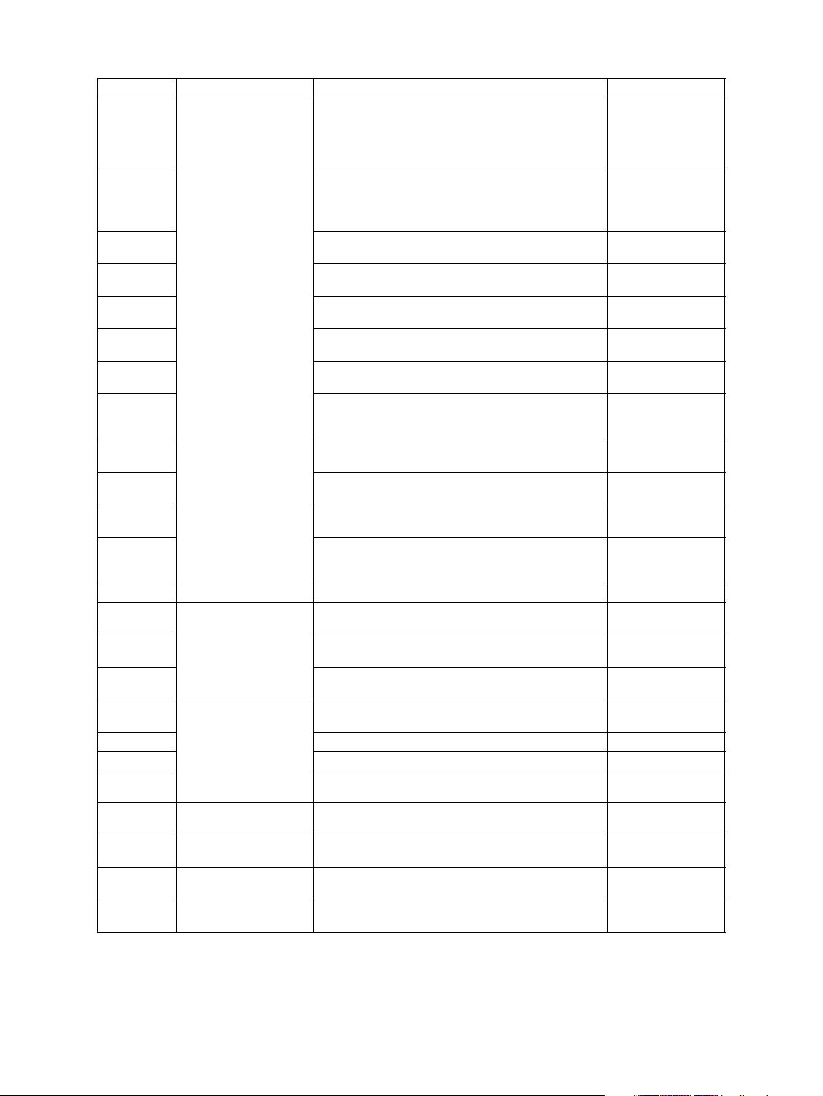
Error code Classification Contents Troubleshooting
E110 Paper misfeeding ADU misfeeding (Paper not reaching the registra-
Ch.5.1.2
tion sensor): The paper which has passed through
ADU does not reach the registration sensor during
duplex printing.
E120 Bypass misfeeding (Paper not reaching the regis-
Ch.5.1.2
tration sensor): The paper fed from the bypass tray
does not reach the registration sensor.
E130 Upper drawer misfeeding (Paper not reaching the
Ch.5.1.2
upper drawer feed sensor): The paper fed from the
upper drawer does not reach the upper drawer feed
sensor.
E140 Lower drawer misfeeding (Paper not reaching the
Ch.5.1.2
lower drawer feed sensor): The paper fed from the
lower drawer does not reach the lower drawer feed
sensor.
E150 PFP upper drawer misfeeding (Paper not reaching
Ch.5.1.2
the PFP upper drawer feed sensor): The paper fed
from the PFP upper drawer does not reach the PFP
upper drawer feed sensor.
E160 PFP lower drawer misfeeding (Paper not reaching
Ch.5.1.2
the PFP lower drawer feed sensor): The paper fed
from the PFP lower drawer does not reach the PFP
lower drawer feed sensor.
E190 LCF misfeeding (Paper not reaching the LCF feed
Ch.5.1.2
sensor): The paper fed from the LCF does not
reach the LCF feed sensor.
E200 Paper transport jam Upper drawer transport jam (Paper not reaching the
Ch.5.1.3
registration sensor): The paper does not reach the
registration sensor after it has passed the upper
drawer feed sensor.
e-STUDIO281c/351c/451c ERROR CODE AND SELF-DIAGNOSTIC MODE June 2005 © TOSHIBA TEC
2 - 2

Error code Classification Contents Troubleshooting
E210 Paper transport jam Lower drawer transport jam (Paper not reaching the
Ch.5.1.3
registration sensor): The paper does not reach the
registration sensor after it has passed the upper
drawer feed sensor.
E220 Lower drawer transport jam (Paper not reaching the
Ch.5.1.3
upper drawer feed sensor): The paper does not
reach the upper drawer feed sensor after it has
passed the lower drawer feed sensor.
E300 PFP upper drawer transport jam (Paper not reach-
Ch.5.1.3
ing the registration sensor): The paper does not
reach the registration sensor after it has passed the
upper drawer feed sensor.
E310 PFP upper drawer transport jam (Paper not reach-
Ch.5.1.3
ing the upper drawer feed sensor): The paper does
not reach the upper drawer feed sensor after it has
passed the lower drawer feed sensor.
E320 PFP upper drawer transport jam (Paper not reach-
Ch.5.1.3
ing the lower drawer feed sensor): The paper does
not reach the lower drawer feed sensor after it has
passed the PFP upper drawer feed sensor.
E330 PFP lower drawer transport jam (Paper not reach-
Ch.5.1.3
ing the registration sensor): The paper does not
reach the registration sensor after it has passed the
upper drawer feed sensor.
E340 PFP lower drawer transport jam (Paper not reach-
Ch.5.1.3
ing the upper drawer feed sensor): The paper does
not reach the upper drawer feed sensor after it has
passed the lower drawer feed sensor.
E350 PFP lower drawer transport jam (Paper not reach-
Ch.5.1.3
ing the lower drawer feed sensor): The paper does
not reach the lower drawer feed sensor after it has
passed the PFP upper drawer feed sensor.
E360 PFP lower drawer transport jam (Paper not reach-
Ch.5.1.3
ing the PFP upper drawer feed sensor): The paper
does not reach the PFP upper drawer feed sensor
after it has passed the PFP lower drawer feed sensor.
E400 Cover open jam Jam access cover open jam: The jam access cover
Ch.5.1.3
has opened during printing.
E410 Front cover open jam: The front cover has opened
Ch.5.1.5
during printing.
E420 Cover open jam PFP side cover open jam: The PFP side cover has
Ch.5.1.5
opened during printing.
E430 ADU open jam: The ADU has opened during print-
Ch.5.1.5
ing.
E440 Side cover open jam: The side cover has opened
Ch.5.1.5
during printing.
E450 LCF side cover open jam: The LCF side cover has
Ch.5.1.5
opened during printing.
E480 Bridge unit open jam: The bridge unit has opened
Ch.5.1.5
during printing.
E510 Paper transport jam
(ADU section)
Jam not reaching the ADU entrance sensor: The
paper does not reach the ADU entrance sensor
Ch.5.1.3
after it is switchbacked in the exit section.
E520 Stop jam in the ADU: The paper does not reach the
Ch.5.1.3
ADU exit sensor after it has passed the ADU
entrance sensor.
2
June 2005 © TOSHIBA TEC e-STUDIO281c/351c/451c ERROR CODE AND SELF-DIAGNOSTIC MODE
2 - 3

Error code Classification Contents Troubleshooting
E550 Other paper jam Paper remaining jam on the transport path: The
Ch.5.1.4
paper is remaining on the transport path when printing is finished (caused by a multiple paper feeding).
E712 RADF jam Jam not reaching the original registration sensor:
Ch.5.1.6
The original fed from the original feeding tray does
not reach the original registration sensor.
E713 Cover open jam in the read ready status: Jam
Ch.5.1.6
caused by opening of the RADF jam access cover
or front cover while the RADF is waiting for the
scanning start signal from the equipment.
E714 Feed signal reception jam: The feed signal is
Ch.5.1.6
received even no original exists on the original
feeding tray.
E721 Jam not reaching the read sensor: The original
Ch.5.1.6
does not reach the read sensor after it has passed
the registration sensor (when scanning obverse
side) or the reverse sensor (when scanning reverse
side).
E722 Jam not reaching the original exit/reverse sensor
Ch.5.1.6
(during scanning): The original which passed the
read sensor does not reach the original exit/reverse
sensor when it is transported from the scanning
section to exit section.
E724 Stop jam at the original registration sensor: The
Ch.5.1.6
trailing edge of the original does not pass the original registration sensor after its leading edge has
reached this sensor.
E725 Stop jam at the read sensor: The trailing edge of the
Ch.5.1.6
original does not pass the read sensor after its leading edge has reached this sensor.
E731 Stop jam at the original exit/reverse sensor: The
Ch.5.1.6
trailing edge of the original does not pass the original exit/reverse sensor after its leading edge has
reached this sensor.
E860 RADF jam access cover open: The RADF jam
Ch.5.1.6
access cover has opened during RADF operation.
E870 RADF open jam: RADF has opened during RADF
Ch.5.1.6
operation.
E910 Finisher jam
(Bridge unit)
Jam at the bridge unit transport sensor 1: The
paper does not reach the bridge unit transport sen-
Ch.5.1.7 [ 1 ]
sor 1 after it has passed the exit sensor.
E920 Stop jam at the bridge unit transport sensor 1: The
Ch.5.1.7 [ 1 ]
trailing edge of the paper does not pass the bridge
unit transport sensor 1 after its leading edge has
reached the sensor.
E930 Jam at the bridge unit transport sensor 2: The trail-
Ch.5.1.7 [ 1 ]
ing edge of the paper does not reach the bridge unit
transport sensor 2 after its leading edge has
reached the bridge unit transport sensor 1.
E940 Stop jam at the bridge unit transport sensor 2: The
Ch.5.1.7 [ 1 ]
trailing edge of the paper does not pass the bridge
unit transport sensor 2 after its leading edge has
reached the bridge unit transport sensor 2.
E9F0 Finisher jam
(Punch unit)
Punching jam: Punching is not performed properly.
[MJ-1023/1024 (when MJ-6004 is installed)]
Ch.5.1.7 [ 4 ]
e-STUDIO281c/351c/451c ERROR CODE AND SELF-DIAGNOSTIC MODE June 2005 © TOSHIBA TEC
2 - 4
05/07
Error code Classification Contents Troubleshooting
EA10 Finisher jam
(Finisher section)
Paper transport delay jam: The paper which has
passed the bridge
Ch.5.1.7 [ 2 ]
unit does not reach the inlet sensor. [MJ-1022/
1023/1024]
EA20 Paper transport stop jam:
Ch.5.1.7 [ 2 ]
(1) The paper does not pass through the inlet sen-
sor.
[MJ-1022/1023/1024]
(2) The paper has passed through the inlet sensor
but does not reach or pass the feed path sensor
or processing tray sensor.
[MJ-1023/1024]
EA30 Power-ON jam:
Ch.5.1.7 [ 2 ]
(1) Paper exists at the inlet sensor when power is
turned ON.
[MJ-1022/1023/1024]
(2) Paper exists at the feed path sensor or pro-
cessing tray sensor when power is turned ON.
[MJ-1023/1024]
EA40 Finisher jam
(Finisher section)
Door open jam:
1) The finisher has been released from the equip-
Ch.5.1.7 [ 2 ]
ment during printing. [MJ-1022]
2) The upper/front cover of the finisher section or
the upper/ front door of the puncher section has
opened during printing. [MJ-1023/1024]
EA50 Stapling jam: Stapling is not performed properly.
Ch.5.1.7 [ 2 ]
[MJ-1022/1023/1024]
EA60 Early arrival jam: The inlet sensor detects the paper
Ch.5.1.7 [ 2 ]
earlier than a specified timing. [MJ-1022/1023/
1024]
EA70 Stack delivery jam: It cannot deliver the stack of
Ch.5.1.7 [ 2 ]
paper on the intermediary process tray to the stack
tray. [MJ-1022]
EA80 Finisher jam
(Saddle stitcher sec-
EA90 Door open jam: The delivery cover or inlet cover
tion)
Stapling jam: Stapling is not performed properly.
[MJ-1024]
Ch.5.1.7 [ 3 ]
Ch.5.1.7 [ 3 ]
has opened dur-ing printing [MJ-1024].
EAA0 Power-ON jam: Paper exists at No.1 paper sensor,
Ch.5.1.7 [ 3 ]
No. 2 paper sensor, No.3 paper sensor, vertical
path paper sensor or delivery sensor when power is
turned ON. [MJ-1024]
EAB0 Transport stop jam: The paper which passed
Ch.5.1.7 [ 3 ]
through the inlet sensor does not reach or pass
No.1 paper sensor, No. 2 paper sensor, No.3 paper
sensor or delivery sensor. [MJ-1024]
EAC0 Transport delay jam: The paper which has reached
Ch.5.1.7 [ 3 ]
the inlet sensor does not pass through the inlet sensor. [MJ-1024]
EAD0 Other paper jam Print end command time-out jam: The printing has
Ch.5.1.7 [ 5 ]
not finished normally because of the communication error between the SYS board and LGC board
at the end of printing.
EAE0 Finisher jam Receiving time time-out jam: The printing has been
Ch.5.1.7 [ 5 ]
interrupted because of the communication error
between the equipment and finisher when the
paper is transported from the equipment to the finisher.
2
June 2005 © TOSHIBA TEC e-STUDIO281c/351c/451c ERROR CODE AND SELF-DIAGNOSTIC MODE
2 - 5

Error code Classification Contents Troubleshooting
EAF0 Finisher jam
(Finisher section)
Stack return jam: It cannot load the paper which
passed through the delivery roller on the intermedi-
Ch.5.1.7 [ 2 ]
ary process tray. [MJ-1022]
EB30 Finisher jam Ready time time-out jam: The equipment judges
Ch.5.1.7 [ 5 ]
that the paper transport to the finisher is disabled
because of the communication error between the
equipment and finisher at the start of printing.
EB50 Paper transport jam Paper remaining on the transport path: The multiple
Ch.5.1.3
feeding of preceding paper caused the misfeeding
of upcoming paper.
EB60 Paper remaining on the transport path: The multiple
Ch.5.1.3
feeding of preceding paper caused the misfeeding
of upcoming paper (redetection after no jam is
detected at [EB50]).
e-STUDIO281c/351c/451c ERROR CODE AND SELF-DIAGNOSTIC MODE June 2005 © TOSHIBA TEC
2 - 6

2.1.2 Service call
Error code Classification Contents Troubleshooting
C010 Drive system related
service call
C020 Developer motor abnormality: The developer motor
C030 Transport motor abnormality: The transport motor is
C040 Paper feeding system
related service call
C130 Upper drawer tray abnormality: The upper drawer
C140 Lower drawer tray abnormality: The lower drawer
C150 PFP upper drawer tray abnormality: The PFP upper
C160 PFP lower drawer tray abnormality: The PFP lower
C180 LCF tray-up motor abnormality: The LCF tray-up
C1A0 LCF end fence motor abnormality: The LCF end
C1B0 LCF transport motor abnormality: The LCF trans-
C260 Scanning system
related service call
C270 Carriage home position sensor not turning OFF
C280 Carriage home position sensor not turning ON
C360 Copy process related
service call
Main motor abnormality: The main motor is not
rotating normally.
is not rotating normally.
not rotating normally.
PFP motor abnormality: The PFP motor is not rotating normally. (the case that paper can be fed from
any drawer except the PFP)
tray-up motor is not rotating or the upper drawer
tray is not moving normally. (the case that paper
can be fed from any drawer except the upper
drawer)
tray-up motor is not rotating or the lower drawer tray
is not moving normally. (the case that paper can be
fed from any drawer except the lower drawer)
drawer tray-up motor is not rotating or the PFP
upper drawer tray is not moving normally. (the case
that paper can be fed from any drawer except the
PFP upper drawer)
drawer tray-up motor is not rotating or the PFP
lower drawer tray is not moving normally. (the case
that paper can be fed from any drawer except the
PFP lower drawer)
motor is not rotating or the LCF tray is not moving
normally. (the case that paper can be fed from any
drawer except the LCF)
fence motor is not rotating or the LCF end fence is
not moving normally. (the case that paper can be
fed from any drawer except the LCF)
port motor is not rotating normally. (the case that
paper can be fed from any drawer except the LCF)
Peak detection error: Lighting of the exposure lamp
(white reference) is not detected when power is
turned ON.
within a specified period of time: The carriage does
not shift from its home position in a specified time.
within a specified period of time: The carriage does
not reach to its home position in a specified period
of time.
Charger cleaner motor abnormality: Charger
cleaner motor is not rotating or wire cleaner is not
moving normally.
Ch.5.1.8
Ch.5.1.8
Ch.5.1.8
Ch.5.1.9
Ch.5.1.9
Ch.5.1.9
Ch.5.1.9
Ch.5.1.9
Ch.5.1.9
Ch.5.1.9
Ch.5.1.9
Ch.5.1.10
Ch.5.1.10
Ch.5.1.10
Ch.5.1.18
2
June 2005 © TOSHIBA TEC e-STUDIO281c/351c/451c ERROR CODE AND SELF-DIAGNOSTIC MODE
2 - 7
Error code Classification Contents Troubleshooting
C411 Fuser unit related ser-
vice call
Thermistor or heater abnormality at power-ON:
Abnormality of the thermistor is detected when
Ch.5.1.11
power is turned ON or the temperature of the fuser
roller does not rise in a specified period of time after
power is turned ON.
C412 Thermistor/heater abnormality at power-ON: Ther-
Ch.5.1.11
mistor abnormality is detected at power-ON or the
fuser roller temperature does not rise within a specified period of time after power-ON.
C443 Heater abnormality after abnormality judgment (not
Ch.5.1.11
reaching to intermediate temperature)
C445 Heater abnormality after abnormality judgment
Ch.5.1.11
(pre-running end temperature abnormality)
C446 Heater abnormality after abnormality judgment
Ch.5.1.11
(pre-running end temperature abnormality)
C447 Heater abnormality after abnormality judgment
Ch.5.1.11
(temperature abnormality at ready status)
C449 Heater abnormality after abnormality judgment
Ch.5.1.11
(overheating)
C471 IH power voltage abnormality or IH initial abnormal-
Ch.5.1.11
ity
(IH board initial abnormality)
C472 IH power voltage abnormality (power supply abnor-
Ch.5.1.11
mality)
C475 IH power voltage abnormality (power supply abnor-
Ch.5.1.11
mality when door is opened)
C480 Overheating of IGBT: The temperature of the IGBT
Ch.5.1.11
rises abnormally.
C490 IH control circuit or IH coil abnormality: Abnormality
Ch.5.1.11
is detected in IH control circuit or IH coil is broken/
shorted.
C4B0 Fuser unit counter abnormality Ch.5.1.11
C550 Optional communica-
tion related service call
C570 Communication error between Engine-CPU and
RADF I/F error: Communication error has occurred
between the RADF and the scanner.
Ch.5.1.12
Ch.5.1.12
IPC board
C580 Communication error between IPC board and fin-
Ch.5.1.12
isher
C900 Circuit related service
call
Connection error between SYS board and LGC
board
Ch.5.1.14
C940 Engine-CPU abnormality Ch.5.1.14
C950 LGC board memory abnormality Ch.5.1.14
C960 Connection error between LGC board and DRV
Ch.5.1.14
board, ID abnormality
C970 Process related ser-
vice call
C9E0 Circuit related service
call
CA10 Laser optical unit
related service call
CA20 H-Sync detection error: H-Sync signal detection PC
High-voltage transformer abnormality: Leakage of
the main charger is detected.
Connection error between SLG board and SYS
board, ID abnormality
Polygonal motor abnormality: The polygonal motor
is not rotating normally.
Ch.5.1.18
Ch.5.1.14
Ch.5.1.15
Ch.5.1.15
board cannot detect laser beams.
e-STUDIO281c/351c/451c ERROR CODE AND SELF-DIAGNOSTIC MODE June 2005 © TOSHIBA TEC
2 - 8

Error code Classification Contents Troubleshooting
CB20 Finisher related ser-
vice call
CB30 Tray 1/Tray 2 shift motor abnormality: Tray 1/Tray 2
Delivery motor abnormality: Delivery motor or delivery roller is not rotating normally. [MJ-1022]
Ch.5.1.16
Ch.5.1.16
shift motor is not rotating or delivery tray is not moving normally. [MJ-1023/1024]
CB40 Rear aligning plate motor abnormality: Rear align-
Ch.5.1.16
ing plate motor is not rotating or aligning plate is not
moving normally. [MJ-1023/1024]
CB50 Staple motor abnormality: Staple motor is not rotat-
Ch.5.1.16
ing or stapler is not moving normally. [MJ-1022/
1023/1024]
CB60 Stapler shift motor abnormality: Stapler shift motor
Ch.5.1.16
is not rotating or staple unit is not moving normally.
[MJ-1023/1024]
CB80 Backup RAM data abnormality:
Ch.5.1.16
1) Abnormality of checksum value on finisher con-
troller PC board is detected when the power is
turned ON. [MJ-1023/1024]
2) Abnormality of checksum value on punch con-
troller PC board is detected when the power is
turned ON. [MJ-1023/1024 (when MJ-6004 is
installed)]
CB90 Paper pushing plate motor abnormality: Paper
Ch.5.1.16
pushing plate motor is not rotating or paper pushing
plate is not moving normally. [MJ-1024]
CBA0 Stitch motor (front) abnormality: Stitch motor (front)
Ch.5.1.16
is not rotating or rotary cam is not moving normally.
[MJ-1024]
CBB0 Stitch motor (rear) abnormality: Stitch motor (rear)
Ch.5.1.16
is not rotating or rotary cam is not moving normally.
[MJ-1024]
CBC0 Alignment motor abnormality: Alignment motor is
Ch.5.1.16
not rotating or aligning plate is not moving normally.
[MJ-1024]
CBD0 Guide motor abnormality: Guide motor is not rotat-
Ch.5.1.16
ing or guide is not moving normally. [MJ-1024]
CBE0 Paper folding motor abnormality: Paper folding
Ch.5.1.16
motor or paper folding roller is not rotating normally.
[MJ-1024]
CBF0 Paper positioning plate motor abnormality: Paper
Ch.5.1.16
positioning plate motor is not rotating or paper positioning plate is not moving normally. [MJ-1024]
CC00 Sensor connector abnormality: Connector of guide
Ch.5.1.16
home position sensor, paper pushing plate home
position sensor or paper pushing plate top position
sensor is disconnected. [MJ-1024]
CC10 Micro switch abnormality: With all covers closed,
Ch.5.1.16
inlet door switch, delivery door switch or front cover
switch is open. [MJ-1024]
2
June 2005 © TOSHIBA TEC e-STUDIO281c/351c/451c ERROR CODE AND SELF-DIAGNOSTIC MODE
2 - 9

Error code Classification Contents Troubleshooting
CC20 Finisher related ser-
vice call
Communication error between finisher and saddle
stitcher: Communication error between finisher con-
Ch.5.1.16
troller PC board and saddle stitcher controller board
[MJ-1023/1024]
CC30 Stack processing motor abnormality: The stack pro-
Ch.5.1.16
cessing motor is not rotating or the stack delivery
belt is not moving normally. [MJ-1022]
CC40 Swing motor abnormality: Swing motor is not rotat-
Ch.5.1.16
ing or swing unit is not moving normally. [MJ-1023/
1024]
CC50 Horizontal registration motor abnormality: Horizon-
Ch.5.1.16
tal registration motor is not rotating or puncher is
not shifting normally. [MJ-1023/1024 (when MJ6004 is installed)]
CC60 Punch motor abnormality: Punch motor is not rotat-
Ch.5.1.16
ing or puncher is not shifting normally. [MJ-1023/
1024 (when MJ-6004 is installed)]
CC80 Front alignment motor abnormality: Front alignment
Ch.5.1.16
motor is not rotating or front aligning plate is not
moving normally. [MJ-1022]
Front aligning plate motor abnormality: Front aligning plate motor is not rotating or aligning plate is not
moving normally. [MJ-1023/1024]
CC90 Upper stack tray lift motor abnormality: The upper
Ch.5.1.16
stack tray lift motor is not rotating or the upper stack
tray is not moving normally. [MJ-1022]
CCA0 Lower stack tray lift motor abnormality: The lower
Ch.5.1.16
stack tray lift motor is not rotating or the lower stack
tray is not moving normally. [MJ-1022]
CCB0 Rear jogging motor abnormality: The rear jogging
Ch.5.1.16
motor is not rotating or the rear jogging plate is not
moving normally. [MJ-1022]
CCD0 Stack ejection motor abnormality: Stack ejection
Ch.5.1.16
motor or stack ejection roller is not rotating normally. [MJ-1023/1024]
CCE0 Paper trailing edge assist motor abnormality: Paper
Ch.5.1.16
trailing edge assist motor is not rotating or paper
trailing edge assist is not moving normally. [MJ1023/1024]
CCF0 Gear changing motor abnormality: Gear changing
Ch.5.1.16
motor is not rotating normally. [MJ-1023/1024]
CE00 Communication error between finisher and punch
Ch.5.1.16
unit: Communication error between finisher controller PC board and punch controller PC board [MJ1023/1024 (when MJ-6004 is installed)]
CE10 Image control related
service call
Image quality sensor abnormality (OFF level): The
output value of this sensor is out of a specified
Ch.5.1.17
range when sensor light source is OFF.
CE20 Image quality sensor abnormality (no pattern level):
Ch.5.1.17
The output value of this sensor is out of a specified
range when the image quality control test pattern is
not formed.
CE40 Image quality control test pattern abnormality: The
Ch.5.1.17
test pattern is not formed normally.
CE50 Temperature/humidity sensor abnormality: The out-
Ch.5.1.17
put value of this sensor is out of a specified range.
CE90 Drum thermistor abnormality: The output value of
Ch.5.1.17
the drum thermistor is out of a specified range.
e-STUDIO281c/351c/451c ERROR CODE AND SELF-DIAGNOSTIC MODE June 2005 © TOSHIBA TEC
2 - 10

Error code Classification Contents Troubleshooting
CEA0 Copy process related
service call
Revolver home position detection abnormality: It
cannot detect that the revolver is at its home posi-
Ch.5.1.18
tion.
CEB0 Black developer unit lifting movement abnormality:
Ch.5.1.18
The black developer unit does not move up or down
normally (lifting cam does not operate normally).
CEC0 Copy process related
service call
2nd transfer roller position detection abnormality:
The 2nd transfer roller does not contact/release
Ch.5.1.18
normally.
CEE0 Transfer belt position detection abnormality (normal
Ch.5.1.18
speed): The home position of the transfer belt cannot be detected.
CEE1 Transfer belt position detection abnormality (when
Ch.5.1.18
decelerating): Reference position of the transfer
belt cannot be detected.
CEF0 Revolver motor abnormality: Revolver motor is not
Ch.5.1.18
rotating or revolver is not moving normally.
CF20 Toner density control
related service call
Toner density detection voltage abnormality: The
output value of the color auto-toner sensor in print-
Ch.5.1.19
ing is out of a specified range.
CF30 Reference plate detection voltage abnormality: The
Ch.5.1.19
output value of the color auto-toner sensor against
the reference plate is out of a specified range at the
light amount correction during an auto-toner adjustment or when a print job has finished.
CF40 Light amount correction voltage abnormality: The
Ch.5.1.19
light amount correction is not finished normally during an auto-toner adjustment or when a print job
has finished, or the output value of the sensor is out
of a specified range when the light amount correction has finished.
CF50 Color auto-toner sensor abnormality: The connec-
Ch.5.1.19
tion of the color auto-toner sensor cannot be
detected at the initialization, or the output value of
color auto-toner sensor when the revolver starts
rotating for initialization is out of a specified range.
F070 Communication
related service call
F090 Circuit related service
F091 NVRAM abnormality on the SYS board Ch.5.1.14
call
Communication error between System-CPU and
Ch.5.1.12
Engine-CPU
SRAM abnormality on the SYS board Ch.5.1.14
F092 SRAM and NVRAM abnormality on the SYS board Ch.5.1.14
F100 Other service call HDD format error: HDD cannot be initialized nor-
Ch.5.1.20
mally.
F101 HDD unmounted: Connection of HDD cannot be
Ch.5.1.20
detected.
F102 HDD start error: HDD cannot become ‘Ready’ state. Ch.5.1.20
F103 HDD transfer time-out: Reading/writing cannot be
Ch.5.1.20
performed in the specified period of time.
F104 HDD data error: Abnormality is detected in the data
Ch.5.1.20
of HDD.
F105 HDD other error Ch.5.1.20
F106 Point and Print partition damage Ch.5.1.20
F107 /BOX partition damage Ch.5.1.20
F108 /SHA partition damage Ch.5.1.20
2
June 2005 © TOSHIBA TEC e-STUDIO281c/351c/451c ERROR CODE AND SELF-DIAGNOSTIC MODE
2 - 11

Error code Classification Contents Troubleshooting
F110 Communication
related service call
Communication error between System-CPU and
Scanner-CPU
Ch.5.1.12
F111 Scanner response abnormality Ch.5.1.12
F120 Other service call Database abnormality: Database is not operating
Ch.5.1.20
normally.
F130 Invalid MAC address Ch.5.1.20
F200 Data overwrite kit (GP-1060) is taken off Ch.5.1.20
F350 Circuit related service
SLG board abnormality Ch.5.1.14
call
e-STUDIO281c/351c/451c ERROR CODE AND SELF-DIAGNOSTIC MODE June 2005 © TOSHIBA TEC
2 - 12
05/11

2.1.3 Error in Internet FAX / Scanning Function
1) Internet FAX related error
Error code Classification Troubleshooting
1C10 System access abnormality
1C11 Insufficient memory
1C12 Message reception error
1C13 Message transmission error
1C14 Invalid parameter
1C15 Exceeding file capacity
1C20 System management module access abnormality
1C21 Job control module access abnormality
1C22 Job control module access abnormality
1C30 Directory creation failure
1C31 File creation failure
1C32 File deletion failure
1C33 File access failure
1C40 Image conversion abnormality
1C60 HDD full failure during processing
1C61 Address Book reading failure
1C62 Memory acquiring failure
1C63 Terminal IP address unset
1C64 Terminal mail address unset
1C65 SMTP address unset
1C66 Server time time-out error
1C67 NIC time time-out error
1C68 NIC access error
1C69 SMTP server connection error
1C6A HOST NAME error
1C6B Terminal mail address error
1C6C Destination mail address error
1C6D System error
1C70 SMTP client OFF Ch.5.1.21 [ 1 ]
1C71 SMTP authentication error
1C72 POP before SMTP error
1C80 Internet FAX transmission failure when processing E-mail job received Ch.5.1.21 [ 1 ]
1C81 Onramp Gateway transmission failure
1C82 Internet FAX transmission failure when processing FAX job received
1CC0 Job canceling -
1CC1 Power failure
Ch.5.1.21 [ 1 ]
Ch.5.1.21 [ 1 ]
Ch.5.1.21 [ 1 ]
Ch.5.1.21 [ 1 ]
Ch.5.1.21 [ 1 ]
Ch.5.1.21 [ 1 ]
Ch.5.1.21 [ 1 ]
Ch.5.1.21 [ 1 ]
Ch.5.1.21 [ 1 ]
Ch.5.1.21 [ 1 ]
Ch.5.1.21 [ 1 ]
Ch.5.1.21 [ 1 ]
Ch.5.1.21 [ 1 ]
Ch.5.1.21 [ 1 ]
Ch.5.1.21 [ 1 ]
Ch.5.1.21 [ 1 ]
Ch.5.1.21 [ 1 ]
Ch.5.1.21 [ 1 ]
Ch.5.1.21 [ 1 ]
Ch.5.1.21 [ 1 ]
Ch.5.1.21 [ 1 ]
Ch.5.1.21 [ 1 ]
Ch.5.1.21 [ 1 ]
Ch.5.1.21 [ 1 ]
Ch.5.1.21 [ 1 ]
Ch.5.1.21 [ 1 ]
Ch.5.1.21 [ 1 ]
Ch.5.1.21 [ 1 ]
Ch.5.1.21 [ 1 ]
Ch.5.1.21 [ 1 ]
Ch.5.1.21 [ 1 ]
Ch.5.1.21 [ 1 ]
Ch.5.1.21 [ 1 ]
2
June 2005 © TOSHIBA TEC e-STUDIO281c/351c/451c ERROR CODE AND SELF-DIAGNOSTIC MODE
2 - 13

2) RFC related error
Error code
2500 Syntax error, command unrecog-
2501 Syntax error in parameters or argu-
2503 Bad sequence of commands Destination mail address error
2504 Command parameter not imple-
2550 Mailbox unavailable Destination mail address error
2551 User not local Destination mail address error
2552 Insufficient system storage Terminal/Destination mail address
2553 Mailbox name not allowed Destination mail address error
Message displayed in
the TopAccess screen
nized
ments
mented
Contents Troubleshooting
HOST NAME error(RFC: 500)
Destination mail address error
(RFC: 500)
Terminal mail address error
(RFC: 500)
HOST NAME error(RFC: 501)
Destination mail address error
(RFC: 501)
Terminal mail address error
(RFC: 501)
(RFC: 503)
HOST NAME error
(RFC: 504)
(RFC: 550)
(RFC: 551)
error
(RFC: 552)
(RFC: 553)
Ch.5.1.21 [ 2 ]
Ch.5.1.21 [ 2 ]
Ch.5.1.21 [ 2 ]
Ch.5.1.21 [ 2 ]
Ch.5.1.21 [ 2 ]
Ch.5.1.21 [ 2 ]
Ch.5.1.21 [ 2 ]
Ch.5.1.21 [ 2 ]
e-STUDIO281c/351c/451c ERROR CODE AND SELF-DIAGNOSTIC MODE June 2005 © TOSHIBA TEC
2 - 14

3) Electronic Filing related error
Error code
2B10 There was no applicable job. No applicable job error in job control
2B11 Job status failed. JOB status abnormality
2B20 Failed to access file. File library function error
2B30 Insufficient disk space. Insufficient disk space in /BOX parti-
2B31 Failed to access Electronic Filing. Status of specified Electronic Filing
2B32 Failed to print Electronic Filing docu-
2B50 Failed to process image. Image library error
2B51 Failed to process print image. List library error
2B71 Document(s) expire(s) in a few days Documents expiring in a few days
2B80 Hard Disk space for Electronic Filing
2B90 Insufficient Memory. Insufficient memory capacity
2BA0 Invalid Box password specified. Invalid Box password
2BB0 Job canceled Job canceling -
2BB1 Power failure occurred Power failure
2BC0 System fatal error. Fatal failure occurred
2BC1 Failed to acquire resource. System management module
2BD0 Power failure occurred during e-Fil-
2BE0 Failed to get machine parameter. Machine parameter reading failure
2BF0 Maximum number of page range is
2BF1 Maximum number of document
2BF2 Maximum number of folder range is
Message displayed in
the TopAccess screen
ment.
nearly full.
ing restoring.
reached.
range is reached.
reached.
Contents Troubleshooting
module
tion
or folder is undefined or being created/deleted
Electronic Filing printing failure:
Specified document can not be
printed because of client’s access
(being edited, etc.).
exist
Hard disk space in /BOX partition is
nearly full (90%).
resource acquiring failure
Power failure occurred during restoring of Electronic Filing
Exceeding maximum number of
pages
Exceeding maximum number of documents
Exceeding maximum number of folders
Ch.5.1.21 [ 3 ]
Ch.5.1.21 [ 3 ]
Ch.5.1.21 [ 3 ]
Ch.5.1.21 [ 3 ]
Ch.5.1.21 [ 3 ]
Ch.5.1.21 [ 3 ]
Ch.5.1.21 [ 3 ]
Ch.5.1.21 [ 3 ]
-
-
Ch.5.1.21 [ 3 ]
Ch.5.1.21 [ 3 ]
Ch.5.1.21 [ 3 ]
Ch.5.1.21 [ 3 ]
Ch.5.1.21 [ 3 ]
Ch.5.1.21 [ 3 ]
Ch.5.1.21 [ 3 ]
Ch.5.1.21 [ 3 ]
Ch.5.1.21 [ 3 ]
Ch.5.1.21 [ 3 ]
2
June 2005 © TOSHIBA TEC e-STUDIO281c/351c/451c ERROR CODE AND SELF-DIAGNOSTIC MODE
2 - 15

4) E-mail related error
Error code
2C10 Illegal Job status System access abnormality
2C11 Not enough memory Insufficient memory
2C12 Illegal Job status Message reception error
2C13 Illegal Job status Message transmission error
2C14 Invalid parameter specified Invalid parameter
2C15 Message size exceeded limit or max-
2C20 Illegal Job status System management module access
2C21 Illegal Job status Job control module access abnor-
2C22 Illegal Job status Job control module access abnor-
2C30 Failed to create directory Directory creation failure
2C31 Failed to create file File creation failure
2C32 Failed to delete file File deletion failure
2C33 Failed to create file File access failure
2C40 Failed to convert image file format Image conversion abnormality
2C60 Failed to process your Job. Insuffi-
2C61 Failed to read AddressBook Address Book reading failure
2C62 Not enough memory Memory acquiring failure
2C63 Invalid Domain Address Terminal IP address unset
2C64 Invalid Domain Address Terminal mail address unset
2C65 Failed to connect to SMTP server SMTP address unset
2C66 Failed to connect to SMTP server Server time time-out error
2C67 Failed to send E-Mail message NIC time time-out error
2C68 Failed to send E-Mail message NIC access error
2C69 Failed to connect to SMTP server SMTP server connection error
2C6A Failed to send E-Mail message HOST NAME error (No RFC error)
2C6B Invalid address specified in From:
2C6C Invalid address specified in To: field Destination mail address error (No
2C6D NIC system error System error
2C70 SMTP service is not available SMTP client OFF Ch.5.1.21 [ 4 ]
2C71 Failed SMTP Authentication SMTP authentication error
2C72 POP Before SMTP Authentication
2C80 Failed to process received E-mail job E-mail transmission failure when pro-
2C81 Failed to process received Fax job Process failure of FAX job received
2CC0 Job canceled Job canceling -
2CC1 Power failure occurred Power failure
Message displayed in
the TopAccess screen
imum size
cient disk space.
field
Failed
Contents Troubleshooting
Exceeding file capacity
abnormality
mality
mality
HDD full failure during processing
Terminal mail address error
RFC error)
POP before SMTP error
cessing E-mail job received
Ch.5.1.21 [ 4 ]
Ch.5.1.21 [ 4 ]
Ch.5.1.21 [ 4 ]
Ch.5.1.21 [ 4 ]
Ch.5.1.21 [ 4 ]
Ch.5.1.21 [ 4 ]
Ch.5.1.21 [ 4 ]
Ch.5.1.21 [ 4 ]
Ch.5.1.21 [ 4 ]
Ch.5.1.21 [ 4 ]
Ch.5.1.21 [ 4 ]
Ch.5.1.21 [ 4 ]
Ch.5.1.21 [ 4 ]
Ch.5.1.21 [ 4 ]
Ch.5.1.21 [ 4 ]
Ch.5.1.21 [ 4 ]
Ch.5.1.21 [ 4 ]
Ch.5.1.21 [ 4 ]
Ch.5.1.21 [ 4 ]
Ch.5.1.21 [ 4 ]
Ch.5.1.21 [ 4 ]
Ch.5.1.21 [ 4 ]
Ch.5.1.21 [ 4 ]
Ch.5.1.21 [ 4 ]
Ch.5.1.21 [ 4 ]
Ch.5.1.21 [ 4 ]
Ch.5.1.21 [ 4 ]
Ch.5.1.21 [ 4 ]
Ch.5.1.21 [ 4 ]
Ch.5.1.21 [ 4 ]
Ch.5.1.21 [ 4 ]
Ch.5.1.21 [ 4 ]
Ch.5.1.21 [ 4 ]
e-STUDIO281c/351c/451c ERROR CODE AND SELF-DIAGNOSTIC MODE June 2005 © TOSHIBA TEC
2 - 16

5) File sharing related error
Error code
2D10 Illegal Job status System access abnormality Ch.5.1.21 [ 5 ]
2D11 Not enough memory Insufficient memory Ch.5.1.21 [ 5 ]
2D12 Illegal Job status Message reception error Ch.5.1.21 [ 5 ]
2D13 Illegal Job status Message transmission error Ch.5.1.21 [ 5 ]
2D14 Invalid parameter specified Invalid parameter Ch.5.1.21 [ 5 ]
2D15 There are too many documents in the
2D20 Illegal Job status System management module access
2D21 Illegal Job status Job control module access abnor-
2D22 Illegal Job status Job control module access abnor-
2D30 Failed to create directory Directory creation failure Ch.5.1.21 [ 5 ]
2D31 Failed to create file File creation failure Ch.5.1.21 [ 5 ]
2D32 Failed to delete file File deletion failure Ch.5.1.21 [ 5 ]
2D33 Failed to create file File access failure Ch.5.1.21 [ 5 ]
2D40 Failed to convert image file format Image conversion abnormality Ch.5.1.21 [ 5 ]
2D60 Failed to copy file File library access abnormality Ch.5.1.21 [ 5 ]
2D61 Invalid parameter specified Invalid parameter Ch.5.1.21 [ 5 ]
2D62 Failed to connect to network destina-
2D63 Specified network path is invalid.
2D64 Logon to file server failed. Check
2D65 There are too many documents in the
2D66 Failed to process your Job. Insuffi-
2D67 FTP service is not available FTP service not available Ch.5.1.21 [ 5 ]
2D68 File Sharing service is not available File sharing service not available Ch.5.1.21 [ 5 ]
2DA0 Expired scan documents deleted
2DA1 Expired Sent Fax documents deleted
2DA2 Expired Received Fax documents
2DA3 Scanned documents in shared folder
2DA4 Sent Fax Documents in shared folder
2DA5 Received Fax Documents in shared
2DA6 Failed to delete file. File deletion failure Ch.5.1.21 [ 5 ]
2DA7 Failed to acquire resource. Resource acquiring failure Ch.5.1.21 [ 5 ]
2DC0 Job canceled Job canceling 2DC1 Power failure occurred Power failure Ch.5.1.21 [ 5 ]
Message displayed in
the TopAccess screen
folder. Failed in creating new document.
tion. Check destination path
Check destination path
username and password
folder. Failed in creating new document.
cient disk space.
from share folder.
from shared folder.
deleted from shared folder.
deleted upon user’s request.
deleted upon user’s request.
folder deleted upon user’s request.
Contents Troubleshooting
Exceeding document number Ch.5.1.21 [ 5 ]
Ch.5.1.21 [ 5 ]
abnormality
Ch.5.1.21 [ 5 ]
mality
mality
File server connection error Ch.5.1.21 [ 5 ]
Invalid network path Ch.5.1.21 [ 5 ]
Login failure Ch.5.1.21 [ 5 ]
Exceeding documents in folder:
Creating new document is failed.
HDD full failure during processing Ch.5.1.21 [ 5 ]
Periodical deletion of scanned documents completed properly.
Periodical deletion of transmitted
FAX documents completed properly.
Periodical deletion of received FAX
documents completed properly.
Manual deletion of scanned documents completed properly.
Manual deletion of transmitted FAX
documents completed properly.
Manual deletion of received FAX
documents completed properly.
Ch.5.1.21 [ 5 ]
Ch.5.1.21 [ 5 ]
2
-
-
-
-
-
-
June 2005 © TOSHIBA TEC e-STUDIO281c/351c/451c ERROR CODE AND SELF-DIAGNOSTIC MODE
2 - 17

6) E-mail reception related error
Error code
3A10 MIME Error has been detected in the
3A11 MIME Error has been detected in the
3A12 MIME Error has been detected in the
3A20 Analyze Error has been detected in
3A21 Analyze Error has been detected in
3A22 Analyze Error has been detected in
3A30 Whole partial mails were not reached
3A40 Partial Mail Error has been detected
3A50 HDD Full Error has been occurred in
3A51 HDD Full Error has been occurred in
3A52 HDD Full Error has been occurred in
3A60 HDD Full Warning has been occurred
3A61 HDD Full Warning has been occurred
3A62 HDD Full Warning has been occurred
3A70 Receiving partial mail was aborted
3A80 Partial mail was received during the
3A81 Partial mail was received during the
3A82 Partial mail was received during the
3B10 Format Error has been detected in
3B11 Format Error has been detected in
3B12 Format Error has been detected in
Message displayed in
the TopAccess screen
received mail.
received mail. This mail has been
transferred to the administrator.
received mail. This mail could not be
transferred to the administrator.
the received mail.
the received mail. This mail has been
transferred to the administrator.
the received mail. This mail could not
be transferred to the administrator.
by timeout.
in the received mail.
this mail.
this mail. This mail has been transferred to the administrator.
this mail. This mail could not be
transferred to the administrator.
in this mail.
in this mail. This mail could not be
transferred to the administrator.
in this mail. This mail could not be
transferred to the administrator.
since the partial mail setting has
been changed to Disable.
partial mail setting is disabled.
partial mail setting is disabled. This
mail has been transferred to the
administrator.
partial mail setting is disabled. This
mail could not be transferred to the
administrator.
the received mail.
the received mail. This mail has been
transferred to the administrator.
the received mail. This mail could not
be transferred to the administrator.
Contents Troubleshooting
E-mail MIME error
E-mail analysis error
Partial mail time-out error
Partial mail related error
Insufficient HDD capacity error
Warning of insufficient HDD capacity
Warning of partial mail interruption
Partial mail reception setting OFF
E-mail format error
Ch.5.1.21 [ 6 ]
Ch.5.1.21 [ 6 ]
Ch.5.1.21 [ 6 ]
Ch.5.1.21 [ 6 ]
Ch.5.1.21 [ 6 ]
Ch.5.1.21 [ 6 ]
Ch.5.1.21 [ 6 ]
Ch.5.1.21 [ 6 ]
Ch.5.1.21 [ 6 ]
Ch.5.1.21 [ 6 ]
Ch.5.1.21 [ 6 ]
Ch.5.1.21 [ 6 ]
Ch.5.1.21 [ 6 ]
Ch.5.1.21 [ 6 ]
Ch.5.1.21 [ 6 ]
Ch.5.1.21 [ 6 ]
Ch.5.1.21 [ 6 ]
Ch.5.1.21 [ 6 ]
Ch.5.1.21 [ 6 ]
Ch.5.1.21 [ 6 ]
Ch.5.1.21 [ 6 ]
e-STUDIO281c/351c/451c ERROR CODE AND SELF-DIAGNOSTIC MODE June 2005 © TOSHIBA TEC
2 - 18

Error code
Message displayed in
the TopAccess screen
3B20 Content-Type Error has been
detected in the received mail.
3B21 Content-Type Error has been
detected in the received mail. This
mail has been transferred to the
administrator.
3B22 Content-Type Error has been
detected in the received mail. This
mail could not be transferred to the
administrator.
3B30 Charset Error has been detected in
the received mail.
3B31 Charset Error has been detected in
the received mail. This mail has been
transferred to the administrator.
3B32 Charset Error has been detected in
the received mail. This mail could not
be transferred to the administrator.
3B40 Decode Error has been detected in
the received mail.
3B41 Decode Error has been detected in
the received mail. This mail has been
transferred to the administrator.
3B42 Decode Error has been detected in
the received mail. This mail could not
be transferred to the administrator.
3C10 Tiff Analyze Error has been detected
in the received mail.
3C11 Tiff Analyze Error has been detected
in the received mail. This mail has
been transferred to the administrator.
3C12 Tiff Analyze Error has been detected
in the received mail. This mail could
not be transferred to the administrator.
3C13 Tiff Analyze Error has been detected
in the received mail.
3C20 Tiff Compression Error has been
detected in the received mail.
3C21 Tiff Compression Error has been
detected in the received mail. This
mail has been transferred to the
administrator.
3C22 Tiff Compression Error has been
detected in the received mail. This
mail could not be transferred to the
administrator.
3C30 Tiff Resolution Error has been
detected in the received mail.
3C31 Tiff Resolution Error has been
detected in the received mail. This
mail has been transferred to the
administrator.
3C32 Tiff Resolution Error has been
detected in the received mail. This
mail could not be transferred to the
administrator.
Contents Troubleshooting
Content-Type error
Charset error
E-mail decode error
TIFF analysis error
E-mail format error
Content-Type error
Ch.5.1.21 [ 6 ]
Ch.5.1.21 [ 6 ]
Ch.5.1.21 [ 6 ]
Ch.5.1.21 [ 6 ]
Ch.5.1.21 [ 6 ]
Ch.5.1.21 [ 6 ]
Ch.5.1.21 [ 6 ]
Ch.5.1.21 [ 6 ]
Ch.5.1.21 [ 6 ]
Ch.5.1.21 [ 6 ]
Ch.5.1.21 [ 6 ]
Ch.5.1.21 [ 6 ]
Ch.5.1.21 [ 6 ]
Ch.5.1.21 [ 6 ]
Ch.5.1.21 [ 6 ]
Ch.5.1.21 [ 6 ]
Ch.5.1.21 [ 6 ]
Ch.5.1.21 [ 6 ]
Ch.5.1.21 [ 6 ]
2
June 2005 © TOSHIBA TEC e-STUDIO281c/351c/451c ERROR CODE AND SELF-DIAGNOSTIC MODE
2 - 19

Error code
Message displayed in
the TopAccess screen
3C40 Tiff Paper Size Error has been
detected in the received mail.
3C41 Tiff Paper Size Error has been
detected in the received mail. This
mail has been transferred to the
administrator.
3C42 Tiff Paper Size Error has been
detected in the received mail. This
mail could not be transferred to the
administrator.
3C50 Offramp Destination Error has been
detected in the received mail.
3C51 Offramp Destination Error has been
detected in the received mail. This
mail has been transferred to the
administrator.
3C52 Offramp Destination Error has been
detected in the received mail. This
mail could not be transferred to the
administrator.
3C60 Offramp Security Error has been
detected in the received mail.
3C61 Offramp Security Error has been
detected in the received mail. This
mail has been transferred to the
administrator.
3C62 Offramp Security Error has been
detected in the received mail. This
mail could not be transferred to the
administrator.
3C70 Power Failure has been occurred in
Email receiving.
3D10 SMTP Destination Error has been
detected in the received mail. This
mail was deleted.
3D20 Offramp Destination limitation Error
has been detected in the received
mail.
3D30 Fax Board Error has been occurred
in the received mail.
3E10 POP3 Connection Error has been
occurred in the received mail.
3E20 POP3 Connection Timeout Error has
been occurred in the received mail.
3E30 POP3 Login Error has been occurred
in the received mail.
3E40 POP3 Login Error occurred in the
received mail.
3F00 File I/O Error has been occurred in
3F10
3F20
this mail. The mail could not be
received until File I/O is recovered.
3F30
3F40
Contents Troubleshooting
Charset error
E-mail decode error
TIFF analysis error
Power failure error
Destination address error
Offramp destination limitation error
FAX board error
POP3 server connection error
POP3 server connection time-out
error
POP3 login error
POP3 login method error
File I/O error
Ch.5.1.21 [ 6 ]
Ch.5.1.21 [ 6 ]
Ch.5.1.21 [ 6 ]
Ch.5.1.21 [ 6 ]
Ch.5.1.21 [ 6 ]
Ch.5.1.21 [ 6 ]
Ch.5.1.21 [ 6 ]
Ch.5.1.21 [ 6 ]
Ch.5.1.21 [ 6 ]
Ch.5.1.21 [ 6 ]
Ch.5.1.21 [ 6 ]
Ch.5.1.21 [ 6 ]
Ch.5.1.21 [ 6 ]
Ch.5.1.21 [ 6 ]
Ch.5.1.21 [ 6 ]
Ch.5.1.21 [ 6 ]
Ch.5.1.21 [ 6 ]
Ch.5.1.21 [ 6 ]
Ch.5.1.21 [ 6 ]
Ch.5.1.21 [ 6 ]
Ch.5.1.21 [ 6 ]
Ch.5.1.21 [ 6 ]
e-STUDIO281c/351c/451c ERROR CODE AND SELF-DIAGNOSTIC MODE June 2005 © TOSHIBA TEC
2 - 20

2.1.4 Printer function error
Following codes are displayed at the end of the user name on the print job log screen.
Error code Contents Troubleshooting
402F Page memory size error - 1200 dpi network print is performed by the equip-
ment with 128 MB (standard) memory.
4031 HDD full during print - Large quantity image data by private print or invalid
network print are saved in HDD.
4032 Private-print-only error: Jobs other than Private print jobs cannot be per-
formed.
4033 Printing data storing limitation error: Printing with its data being stored to the
HDD temporarily (Proof print, Private print, Scheduled print, etc.) cannot be
performed.
4034 e-Filing storing limitation error: Printing with its data being stored to the HDD
(print and e-Filing, print to e-Filing, etc.) cannot be performed.
4035 Local file storing limitation error: Network FAX or Internet FAX cannot be sent
when "Local" is selected for the destination of the file to save.
4036 User authentication error: The user who intended to print a document is not
registered as a user.
A221 Print job cancellation - Print job (copy, list print, network print) is deleted from
the print job screen.
A222 Print job power failure - The power of the equipment is turned OFF during
print job (copy, list print, network print).
A290 Limit over error (Black): The numbers of output pages have exceeded those
specified with both of the department code and the user code at the same
time.
A291 Limit over error (Black): The number of output pages has exceeded the one
specified with the user code.
A292 Limit over error (Black): The number of output pages has exceeded the one
specified with the department code.
A2A0 Limit over error (Color): The numbers of output pages have exceeded those
specified with both of the department code and the user code at the same
time.
A2A1 Limit over error (Color): The number of output pages has exceeded the one
specified with the user code.
A2A2 Limit over error (Color): The number of output pages has exceeded the one
specified with the department code.
Ch.5.1.21 [ 6 ]
Ch.5.1.21 [ 6 ]
Ch.5.1.21 [ 6 ]
Ch.5.1.21 [ 6 ]
Ch.5.1.21 [ 6 ]
Ch.5.1.21 [ 6 ]
Ch.5.1.21 [ 6 ]
Ch.5.1.21 [ 6 ]
Ch.5.1.21 [ 6 ]
Ch.5.1.21 [ 6 ]
Ch.5.1.21 [ 6 ]
Ch.5.1.21 [ 6 ]
Ch.5.1.21 [ 6 ]
Ch.5.1.21 [ 6 ]
Ch.5.1.21 [ 6 ]
2
June 2005 © TOSHIBA TEC e-STUDIO281c/351c/451c ERROR CODE AND SELF-DIAGNOSTIC MODE
2 - 21

<<Error history>>
In the setting mode (08-253), the latest twenty groups of error data will be displayed.
Display example
EA10
99999999 05 06 14 17 57 32 064 064 23621000000
Error code Total counter YY MM DD HH MM SS MMM NNN ABCDEFHIJLO
4 digits 8 digits 12 digits (Year is indicated
3 digits 3 digits 11 digits
with its last two digits.)
A Paper source
0: Not selected 1: Bypass feed 2: LCF 3: Upper drawer 4: Lower drawer 5: PFP upper drawer
6: PFP lower drawer 7: Unused 8: Unused
B Paper size code
0: A5/ST 1: A5-R 2: ST-R 3: LT, 4: A4 5: B5-R 6: LT-R 7: A4-R 8: OTHER/UNIV 9: B5,
A: FOLIO/COMP B: LG C: B4 D: LD E: A3 F: 13"LG G: Unsed H: A6-R I: Post card J: 8.5"SQ
K: A3-wide L: 305×457 mm M: 8K N: 16K-R O: 16K Z: Not selected
C Sort mode/staple mode
0: Non-sort/Non-staple 1: Group 2: Sort 7: Front staple
8: Double staple 9: Rear staple A: Saddle stitch
D ADF mode
0: Unused 1: AUTO FEED (SADF) 2: STACK FEED
E APS/AMS mode
0: Not selected 1: APS 2: AMS
F Duplex mode
0: Not selected 1: Book 2: Double-sided/Single-sided 4: Double-sided/Duplex copying
8: Single-sided/Duplex copying
GUnused
H Image shift
0: Unused 1: Book 2: Left 4: Right
I Editing
0: Unused 1: Masking 2: Trimming 3: Mirror image 4: Unused
J Edge erase/Dual-page
0: Unused 1: Edge erase 2: Dual-page 3: Edge erase & Dual-page
KUnused
L Function
0: Unused 1: Copying 2: FAX/Internet FAX transmission 3: FAX/Internet FAX/E-mail reception printing
4: Unused 5: Printing/List print 6: Scan/E-mail transmission
MMM Primary scanning reproduction ratio (Display in hexadecimal)
(Mx256)+(Mx16)+M
NNN Secondary scanning reproduction ratio (Display in hexadecimal)
(Nx256)+(Nx16)+N
O Color mode
0: Auto color 1: Full color 2: Black 3: Unused 4: Twin color copy 5: Gray scale
6: Unused 7: Image smoothing
e-STUDIO281c/351c/451c ERROR CODE AND SELF-DIAGNOSTIC MODE June 2005 © TOSHIBA TEC
2 - 22

2.2 Self-diagnosis Modes
Mode For start Contents For exit Display
Control panel
check mode
Test mode [0]+[3]+
Test print mode [0]+[4]+
Adjustment
mode
Setting mode [0]+[8]+
List print mode [9]+[START]+
PM support
mode
Firmware
update mode
Note: Note:
To enter the desired mode, turn ON the power while two digital keys designated to each mode
(e.g. [0] and [5]) are pressed simultaneously.
To exit from Adjustment mode and Setting mode:
Shut down the equipment. When the power should be turned OFF, be sure to shut down the equipment by pressing the [ENERGY SAVER] button for a few seconds.
[0]+[1]+
[POWER]
[POWER]
[POWER]
[0]+[5]+
[POWER]
[POWER]
[POWER]
[6]+[START]+
[POWER]
[8]+[9]+
[POWER]
All LEDs on the control panel are lit, and all
the LCD pixels blink.
Checks the status of input/output signals. [POWER]
Outputs the test patterns. [POWER]
Adjusts various items. [POWER]
Sets various items. [POWER]
Prints out the data lists of the codes 05 and
08, PM support mode and pixel counter.
Clears each counter. [POWER]
Performs updating of the system firmware. [POWER]
[POWER]
OFF/ON
OFF/ON
OFF/ON
OFF/ON
OFF/ON
[POWER]
OFF/ON
OFF/ON
OFF/ON
-
100% C A4
TEST MODE
100% P A4
TEST PRINT
100% A A4
TEST MODE
100% D
TEST MODE
100% UA A4
LIST PRINT
100% K
TEST MODE
-
2
<Operation procedure>
• Control panel check mode (01):
[0][1]
[POWER]
LED lit/
LCD blinking
[START]
[START]
(Button check)
[POWER] OFF/ON
(Exit)
Notes:
1. A mode can be canceled by [POWER] OFF/ON when the LED is lit and the LCD is blinking.
2. Button Check
Buttons with LED (Press to turn OFF the LED.)
Buttons without LED (Press to display the message on the control panel.)
Button on touch panel (Press to display the screen on the control panel at power-ON.)
• Test mode (03): Refer to “2.2.1. Input check (test mode 03)” and “2.2.2. Output check (test mode
03)”.
• Test print mode (04): Refer to “2.2.3. Test print mode (04)”.
• Adjustment mode (05): Refer to “2.2.4. Adjustment mode (05)”.
• Setting mode (08): Refer to “2.2.5. Setting mode (08)”.
June 2005 © TOSHIBA TEC e-STUDIO281c/351c/451c ERROR CODE AND SELF-DIAGNOSTIC MODE
2 - 23

• List print mode (9S): The procedure varies depending on the code.
[9][START]
[POWER]
(Code)
101: Adjustment mode (05)
102: Setting mode (08)
[START] [START]
[Digital keys]
Key in the first
code to be printed
[Digital keys]
Key in the last
code to be printed
(Code)
103: PM support mode
104: Stored information of pixel counter (toner cartridge reference)
105: Stored information of pixel counter (service technician reference)
106: Error history (Maximum 1000 items)
107: Error history (Latest 80 items)
• PM support mode (6S):
[6][START]
[POWER]
2: PM Support Screen
(Code)
[START]
(Operation started)
[POWER] OFF/ON
• Firmware update mode (89): Refer to “6. FIRMWARE UPDATING”.
[POWER]
ON
Test print
mode
Adjustment
mode
Setting
mode
Warming up
Normal
Control panel
check mode
[0][1] [0][3] [0][4] [0][5] [0][8] [9][START] [6][START] [8][9]
Test mode
(Exit)
List print
mode
[START]
List starts to
be printed
PM support
mode
[POWER]
OFF/ON
(Exit)
Firmware
update mode
Ready
[POWER]
OFF
*1
To user
State transition diagram of self-diagnosis modes
Fig.2-1
*1 Turn OFF the power after using the self-diagnosis mode, and leave the equipment to the user.
e-STUDIO281c/351c/451c ERROR CODE AND SELF-DIAGNOSTIC MODE June 2005 © TOSHIBA TEC
2 - 24

2.2.1 Input check (Test mode 03)
The status of each input signal can be checked by pressing the [FAX] button, [COPY] button and
the digital keys in the test mode (03).
<Operation procedure>
[0][3]
[POWER]
[START]
Note: Note:
Initialization is performed before the equipment enters the test mode.
[FAX]
or
[COPY]
[Digital keys]
[CLEAR]
(LCD ON)
[POWER] OFF/ON
(Exit)
2
Fig.2-2 Example of display during input check
Items to be checked and the condition of the equipment when the buttons [A] to [H] are highlighted are
listed in the following pages.
June 2005 © TOSHIBA TEC e-STUDIO281c/351c/451c ERROR CODE AND SELF-DIAGNOSTIC MODE
2 - 25

[FAX] button: OFF/[COPY] button: OFF ([FAX] LED: OFF/[COPY] LED: OFF)
Digital
key
[1]
[2]
[3]
[4]
Button Items to check
A Bypass unit connection Not connected Connected
B ADU connection Not connected
C-
D LCF connection Not connected
E-
F-
G-
H LCF drawer detection switch Drawer not installed Drawer present
A PFP upper drawer detection switch Drawer not installed
B-
C PFP upper drawer paper stock sensor Paper almost empty Paper present
D PFP upper drawer feed sensor Paper present No paper
E PFP connection Not connected Connected
F PFP side cover open/close switch Cover opened Cover closed
G PFP upper drawer empty sensor No paper Paper present
H PFP upper drawer tray-up sensor Tray at upper limit
A LCF tray bottom sensor Tray at bottom posi-
B LCF standby side paper misload detection sen-
sor
C-
D-
E-
F-
G-
H Paper stock sensor at LCF feed side Paper present No paper
A PFP lower drawer detection switch Drawer not installed Drawer present
B-
C PFP lower drawer paper stock sensor Paper almost empty Paper present
D PFP lower drawer feed sensor Paper present
E PFP motor rotation status (Motor is rotating at
output mode (03))
F-
G PFP lower drawer empty sensor No paper Paper present
H PFP lower drawer tray-up sensor Tray at upper limit
Highlighted display
e.g.
--
--
--
--
--
position
tion
Properly loaded Paper misload
--
--
--
--
--
--
Abnormal rotation Normal rotation
--
position
Contents
Normal display
e.g.
Connected
Connected
Drawer present
Other than upper
limit position
Other than upper
limit position
No paper
Other than upper
limit position
e-STUDIO281c/351c/451c ERROR CODE AND SELF-DIAGNOSTIC MODE June 2005 © TOSHIBA TEC
2 - 26

Digital
key
[5]
[6]
[7]
[8]
Contents
Button Items to check
Highlighted display
e.g.
A LCF end fence home position sensor Fence home posi-
tion
Normal display
e.g.
Other than home
position
B LCF end fence stop position sensor Fence stop position Other than stop
position
C Empty sensor at LCF standby side No paper Paper present
D LCF side cover open/close switch Cover closed Cover opened
E LCF motor rotation status (Motor is rotating at
Abnormal rotation Normal rotation
output mode (03))
F LCF tray-up sensor Tray at upper limit
position
G LCF feed sensor No paper
Other than upper
limit position
Paper present
H Empty sensor at LCF feed side No paper Paper present
A Lower drawer detection switch Drawer not installed Drawer present
B Upper drawer detection switch Drawer not installed Drawer present
C Lower drawer paper stock sensor Paper almost empty Paper present
D Upper drawer paper stock sensor Paper almost empty Paper present
E Lower drawer empty sensor No paper Paper present
F Upper drawer empty sensor No paper Paper present
G Lower drawer tray-up sensor Tray at upper limit
position
H Upper drawer tray-up sensor Tray at upper limit
position
A-
B-
C-
D-
--
--
--
--
Other than upper
limit position
Other than upper
limit position
E Side cover open/close switch Cover opened Cover closed
F Front cover opening/closing switch Cover opened Cover closed
G-
--
H Exit sensor Paper present No paper
A Bypass feed paper width sensor 3
Bit 1 Bit 0
(Refer to table1)
B Bypass feed paper width sensor 2
Bit 1
Bit 0
(Refer to table1)
C Bypass feed paper width sensor 1
Bit 1
Bit 0
(Refer to table1)
D Bypass feed paper width sensor 0
Bit 1
Bit 0
(Refer to table1)
E Bypass sensor No paper Paper present
F ADU opening/closing switch ADU opened ADU closed
G ADU exit sensor Paper present No paper
H ADU entrance sensor Paper present No paper
2
June 2005 © TOSHIBA TEC e-STUDIO281c/351c/451c ERROR CODE AND SELF-DIAGNOSTIC MODE
2 - 27

Digital
key
[9]
[0]
Contents
Button Items to check
Highlighted display
Normal display
e.g.
A-
B-
C-
D-
E-
--
--
--
--
--
F Key copy counter connection Not connected Connected
G-
H
---
A-
B-
C-
D-
E-
F-
G-
H-
--
--
--
--
--
--
--
--
--
e.g.
Table 1. Relation between the status of the bypass paper width sensor and paper size (width).
Bypass paper width sensor
3210
0111 A3/LD
1011 A4-R/LT-R
1101 A5-R/ST-R
1110 Card size
0011 B4-R/LG
1001 B5-R
Paper width size
e-STUDIO281c/351c/451c ERROR CODE AND SELF-DIAGNOSTIC MODE June 2005 © TOSHIBA TEC
2 - 28

[FAX] button: ON/[COPY] button: OFF ([FAX] LED: ON/[COPY] LED: OFF)
Digital
key
[1]
[2]
[3]
[4]
Button Items to check
A 2nd transfer roller position detection sensor Released Contacted
B Black developer contact timing detection sensor Releasing move-
C Black developer contact position detection sen-
sor
D Main motor rotation status
(Motor is rotating at Output Mode (03))
E Developer motor rotation status
(Motor is rotating at Output Mode (03))
F Transport motor rotation status
(Motor is rotating at Output Mode (03))
G Polygonal motor rotation status
(Motor is rotating at Output Mode (03))
H 24V Power supply Power OFF Power ON
A IPC board connection Not connected Connected
B Color toner cartridge sensor Normally Installation fault
C Revolver home position sensor Home position Other than home
D-
E
F Toner bag full detection sensor Toner bag full Not full
G Black auto-toner sensor connection Not connected Connected
H
A
B
C
D
E
F
G Lower drawer feed sensor No paper Paper present
H Upper drawer feed sensor Paper present No paper
A
B
C
D
E Bridge unit connection Not connected Connected
F Color auto-toner sensor connection Not connected Connected
G
H
---
---
---
---
---
---
---
---
---
---
---
---
---
---
Highlighted display
e.g.
ment
Released position Contacted position
Abnormal rotation Normal rotation
Abnormal rotation Normal rotation
Abnormal rotation Normal rotation
Abnormal rotation Normal rotation
--
Contents
Normal display
e.g.
Contacting movement
2
position
June 2005 © TOSHIBA TEC e-STUDIO281c/351c/451c ERROR CODE AND SELF-DIAGNOSTIC MODE
2 - 29

Digital
key
[5]
[6]
[7]
[8]
[9]
Contents
Button Items to check
Highlighted display
e.g.
Normal display
e.g.
A- --
B- --
C- --
D
E
---
---
F RADF connection RADF connected Not connected
G Platen sensor Platen cove opened Platen cover closed
H Carriage home position sensor Home position Other than home
position
A
B
C
---
---
---
D APS sensor (APS-R) No original Original present
E APS sensor (APS-C) No original
F APS sensor (APS-3) No original
G APS sensor (APS-2) No original
H APS sensor (APS-1) No original
Original present
Original present
Original present
Original present
A RADF tray sensor Original present No original
B RADF empty sensor Original present No original
C RADF jam access cover sensor Cover opened Cover closed
D RADF open/close sensor RADF opened RADF closed
E RADF exit sensor Original present No original
F RADF intermediate sensor Original present No original
G RADF read sensor Original present No original
H RADF registration sensor Original present No original
A
B
C
D
E RADF original length sensor Original present
F RADF original width sensor 1 Original present
G RADF original width sensor 2 Original present
H
A Black toner cartridge switch Cartridge not
---
---
---
---
No original
No original
No original
---
Cartridge installed
installed
B
C
---
---
D Bypass feed sensor No paper Paper present
E Registration sensor Paper present No paper
F
G
---
---
H Transfer belt home position sensor Home position Other tha home
position
e-STUDIO281c/351c/451c ERROR CODE AND SELF-DIAGNOSTIC MODE June 2005 © TOSHIBA TEC
2 - 30

Digital
key
[0]
Contents
Button Items to check
Highlighted display
e.g.
Normal display
e.g.
A Bridge unit transport sensor 2 Paper present No paper
B Bridge unit cover open/close detection switch Cover opened Cover closed
C Bridge unit transport sensor 1 Paper present No paper
D Bridge unit paper full detection sensor Paper not full Paper full
E
F Charger cleaner front position detection switch Cleaner home posi-
G Charger cleaner rear position detection switch Cleaner rear posi-
H
---
Other than home
tion
position
Other than rear posi-
tion
tion
---
2
June 2005 © TOSHIBA TEC e-STUDIO281c/351c/451c ERROR CODE AND SELF-DIAGNOSTIC MODE
2 - 31

[FAX] button: OFF/[COPY] button: ON ([FAX] LED: OFF/[COPY] LED: ON)
Digital
key
[1]
[2]
[3]
[4]
[5]
[6]
[7]
[8]
Button Items to check
- Temperature/humidity sensor (displays temperature inside of the equipment)
- Temperature/humidity sensor (displays humidity
inside of the equipment)
- Drum thermistor (displays drum surface temperature)
A- -B- -C- -D- -E- -F- -G- -H- -A- -B- -C- -D- -E- -F- -G- -H- -A- -B- -C- -D- -E- -F- -G- -H- -A- -B- -C- -D- -E- -F- -G- -H- -A- -B- -C- -D- -E- -F- -G- -H- --
Highlighted display
e.g.
- Temperature [°C]
- Humidity [%RH]
- Temperature [°C]
Contents
Normal display
e.g.
e-STUDIO281c/351c/451c ERROR CODE AND SELF-DIAGNOSTIC MODE June 2005 © TOSHIBA TEC
2 - 32

Contents
Digital
key
[9]
[0]
Button Items to check
A- -B- -C- -D- -E- -F- -G- -H- -A
B
C
D Dongles for other equipments / Other USB
devices
E Judgement for acceptable USB storage device
(*1)
F- -G- -H- --
---
---
---
Highlighted display
e.g.
Connectable Not connectable
Acceptable Not acceptable
Normal display
e.g.
*1
• Be sure to install the USB storage device to the equipment and check if the device can be used with
this code.
• Be sure to turn OFF the write protection (the function to prevent data from erasure by the accidental
recording or deleting) of the USB storage device before performing the check, otherwise this code
cannot be used.
• It may take some time (2 sec. to 10 sec.) before this check is completed depending on the USB storage device.
2
June 2005 © TOSHIBA TEC e-STUDIO281c/351c/451c ERROR CODE AND SELF-DIAGNOSTIC MODE
2 - 33
05/11

2.2.2 Output check (test mode 03)
Status of the output signals can be checked by entering the following codes in the test mode 03.
<Operation procedure>
Procedure 1
[0][3]
[POWER]
(Code)
[START]
Operation
ON
Stop
code
[START]
Operation
OFF
[POWER] OFF/ON
(Exit)
Procedure 2
[0][3]
[POWER]
(Code)
[START] [CLEAR]
Operation
One direction
Test mode
standby
[POWER] OFF/ON
(Exit)
Procedure 3
[0][3]
[POWER]
(Code)
[START] [START]
Operation
ON
Operation
OFF
[CLEAR]
Test mode
standby
[POWER]
OFF/ON
(Exit)
Procedure 4
[0][3]
[POWER]
Code Function Code Function Procedure
101 Main motor ON (Operational without
black developer unit)
102 Toner motor K (normal rotation) ON 152 Code No.102 function OFF 1
103 Polygonal motor (600dpi) ON 153 Code No.103 function OFF 1
108 Registration clutch ON 158 Code No.108 function OFF 1
109 PFP motor ON 159 Code No.109 function OFF 1
110 ADU motor ON 160 Code No.110 function OFF 1
112 Developer motor ON (Operational with
black developer unit)
115 Drum cleaning brush motor ON 165 Code No.115 function OFF 1
116 Transfer belt cleaner auger motor ON 166 Code No.116 function OFF 1
118 Laser ON 168 Code No.118 function OFF 1
120 Exit motor (normal rotation) ON 170 Code No.120 function OFF 1
121 Exit motor (reversal rotation) ON 171 Code No.121 function OFF 1
122 LCF motor ON 172 Code No.122 function OFF 1
123 Transport motor ON 173 Code No.123 function OFF 1
124 Toner motor K (reversal rotation) ON 174 Code No.124 function OFF 1
125 Color auto-toner sensor shutter sole-
noid ON (open)
126 Color auto-toner sensor LED ON 176 Code No.126 function OFF 1
(Code)
[START]
[POWER] OFF
151 Code No.101 function OFF 1
162 Code No.112 function OFF 1
175 Code No.125 function OFF 1
e-STUDIO281c/351c/451c ERROR CODE AND SELF-DIAGNOSTIC MODE June 2005 © TOSHIBA TEC
2 - 34

Code Function Procedure
201 Upper drawer feed clutch ON/OFF 3
202 Lower drawer feed clutch ON/OFF 3
203 Lower transport clutch (high speed) ON/OFF 3
204 Bypass feed clutch ON/OFF 3
205 Lower transport clutch (low speed) ON/OFF 3
206 LCF pickup solenoid ON/OFF 3
207 LCF end fence reciprocating movement 2
208 LCF end fence motor ON/OFF 3
209 LCF feed clutch ON/OFF 3
210 LCF transport clutch ON/OFF 3
218 Key copy counter count up 2
222 ADU clutch ON/OFF 3
225 PFP transport clutch ON/OFF 3
226 PFP upper drawer feed clutch ON/OFF 3
228 PFP lower drawer feed clutch ON/OFF 3
232 Bridge unit gate solenoid ON/OFF 3
235 Discharge LED ON/OFF 3
241 IH board cooling fan (low speed) ON/OFF 3
242 Upper drawer tray-up motor ON (tray up) 2
243 Lower drawer tray-up motor ON (tray up) 2
248 Developer bias (Black) [+DC] ON/OFF 3
249 Developer bias (Black) [-DC] ON/OFF 3
252 Main charger ON/OFF 3
261 Scan motor ON (Automatically stops at limit position, speed can be changed by using
2
ZOOM button)
264 SLG board cooling fan / Scanner unit cooling fan ON (high/low speed) 1
265 SLG board cooling fan / Scanner unit cooling fan OFF 1
267 Scanner exposure lamp ON/OFF 3
268 Laser unit cooling fan (high speed) ON/OFF 3
271 LCF tray-up motor UP/DOWN 2
278 PFP upper drawer tray-up motor ON (tray up) 2
280 PFP lower drawer tray-up motor ON (tray up) 2
281 RADF feed motor ON/OFF (normal rotation) 3
282 RADF feed motor ON/OFF (reverse rotation) 3
283 RADF read motor ON/OFF 3
284 RADF exit/reverse motor ON/OFF (normal rotation) 3
285 RADF exit/reverse motor ON/OFF (reverse rotation) 3
294 RADF reverse solenoid ON/OFF 3
295 Power OFF mode (for 200V series) 4
297 RADF fan motor ON/OFF 3
410 Power supply cooling fan (low speed) ON/OFF 3
411 Power supply cooling fan (high speed) ON/OFF 3
2
June 2005 © TOSHIBA TEC e-STUDIO281c/351c/451c ERROR CODE AND SELF-DIAGNOSTIC MODE
2 - 35

Code Function Procedure
412 Internal cooling fan ON/OFF (low speed) 3
413 Internal cooling fan ON/OFF (high speed) 3
416 IH board cooling fan (high speed) ON/OFF 3
417 Ozone exhaust fan (low speed) ON/OFF 3
418 Ozone exhaust fan (high speed) ON/OFF 3
419 Developer bias (Black) [AC] ON/OFF 3
420 Developer bias (Color) [+DC] ON/OFF 3
421 Developer bias (Color) [-DC1] ON/OFF 3
422 Developer bias (Color) [AC] ON/OFF 3
424 1st transfer roller bias [+] ON/OFF 3
425 1st transfer roller bias [-] ON/OFF 3
426 2nd transfer roller bias [+] ON/OFF 3
427 2nd transfer roller bias [-] ON/OFF 3
428 Drum cleaning blade bias ON/OFF 3
430 Image quality sensor shutter solenoid ON/OFF 3
431 Color developer drive clutch ON/OFF 3
432 Black developer drive clutch ON/OFF 3
433 Black developer lifting clutch ON/OFF 3
435 2nd transfer roller contact clutch ON/OFF 3
437 Transfer belt cleaner clutch ON/OFF 3
439 Upper transport clutch (high speed) ON/OFF 3
440 Upper transport clutch (low speed) ON/OFF 3
442 Color developer toner supply clutch ON/OFF 3
450 Revolver motor ON/OFF (printing operation) 3
451 Revolver motor operation (at standby position) 2
452 Revolver motor operation (at toner cartridge Y access position) 2
453 Revolver motor operation (at toner cartridge M access position) 2
454 Revolver motor operation (at toner cartridge C access position) 2
455 Revolver motor operation (at developer unit Y access position) 2
456 Revolver motor operation (at developer unit M access position) 2
457 Revolver motor operation (at developer unit C access position) 2
458 Revolver motor operation (at home position) 2
459 Revolver motor operation (at developing position) 2
460 Black developer unit lifting movement ON/OFF (continuous lifting movement) 3
461 Charger cleaner motor movement (one reciprocating movement) 2
e-STUDIO281c/351c/451c ERROR CODE AND SELF-DIAGNOSTIC MODE June 2005 © TOSHIBA TEC
2 - 36

2.2.3 Test print mode (test mode 04)
The embedded test pattern can be printed out by keying in the following codes in the test print mode (04).
<Procedure 1>
[0][4]
[POWER]
(Code)
[START]
Operation
Continuous
Test Printing
[CLEAR]
[POWER] OFF/ON
(Exit)
<Procedure 2>
[0][4]
[POWER]
(Code)
[START]
[CLEAR]
Color
selection
[START]
Operation
Continuous
Test Printing
[CLEAR]
[POWER] OFF/ON
(Exit)
Notes:
1. When an error occurs, it is indicated on the panel, but the recovery operation is not performed.
Turn OFF the power and then back ON to clear the error.
2. During test printing, the [CLEAR] button is disabled when “Wait adding toner” is displayed.
Code Types of test pattern Remarks Remarks
142 Grid pattern (black) Pattern width: 2 dots, Pitch: 10 mm 1
204 Grid pattern (color) Pattern width: 1 dot, Pitch: 10 mm 2
219 6% test pattern 2
220 8% test pattern 2
231 Secondary scanning direction 33 grada-
tion steps
237 Halftone 2
262 Pattern for jitter evaluation
(4 lines ON / 4 lines OFF)
270 Image quality control test pattern For checking the image quality control 2
3 pixels standard, Width: 10 mm 2
1 pixel standard, for color deviation correction
2
2
June 2005 © TOSHIBA TEC e-STUDIO281c/351c/451c ERROR CODE AND SELF-DIAGNOSTIC MODE
2 - 37

2.2.4 Adjustment mode (05)
Items in the adjustment mode list in the following pages can be corrected or changed in this adjustment mode
(05). Turn ON the power with pressing the digital keys [0] and [5] simultaneously in order to enter this mode.
When the power should be turned OFF, be sure to shut down the equipment by pressing the [ENERGY SAVER]
button for a few seconds.
Procedure 1
[0][5]
[POWER]
Procedure 2
[0][5]
[POWER]
Procedure 3
[0][5]
[POWER]
[Digital key]
(Code)
[Digital key]
(Code)
[Digital key]
(Code)
[START]
[CANCEL]
[START]
[START]
[CANCEL]
[Digital key]
[FUNCTION CLEAR]
*
(Key in a value)
[CLEAR]
(Corrects value)
Value
()
displayed
[UP]
or
[DOWN]
(Adjust a value)
[CLEAR]
(Corrects value)
[ENTER]
[INTERRUPT]
(Value unchangeable)
[INTERRUPT]
(Stores value in RAM)
[ENTER]
or
[INTERRUPT]
(Stores value in RAM)
*Press [
or
[ENTER]
or
FUNCTION CLEAR
([FAX] [START])
(Test copy)
([FAX] [START])
(Test copy)
[FAX]
[START]
(Test copy)
] to enter minus (-).
[POWER]
OFF/ON
(Exit)
[POWER]
OFF/ON
[POWER]
OFF/ON
(Exit)
(Exit)
Procedure 4
[0][5]
[POWER]
[Digital key]
(Code)
[START]
[CANCEL]
[Digital key]
(Sub code)
(Corrects value)
[START]
[START]
[CLEAR]
[ENTER]
[Digital key]
*[FUNCTION CLEAR]
(Key in a value)
[CLEAR]
(Corrects value)
*Press [FUNCTION CLEAR] to enter minus (-).
or
[INTERRUPT]
Stores value
in RAM
([FAX]
[START])
(Test copy)
[POWER]
OFF/ON
(Exit)
Procedure 5
[CANCEL] or [CLEAR]
[0][5]
[POWER]
e-STUDIO281c/351c/451c ERROR CODE AND SELF-DIAGNOSTIC MODE June 2005 © TOSHIBA TEC
[Digital key]
(Code)
[START]
Automatic
adjustment
[UP]
or
[DOWN]
(Adjust a value)
2 - 38
[ENTER]
or
[INTERRUPT]
Stores value
in RAM
[FAX]
[START]
(Test copy)
[POWER]
OFF/ON
(Exit)

Procedure 6
[0][5]
[POWER]
Procedure 7
[0][5]
[POWER]
Procedure 10
[Digital key]
(Code)
[Digital key]
(Code)
*[CANCEL] or [CLEAR]
[START]
Automatic
adjustment
[FAX] [COPY])
(Test copy)
[POWER]OFF/ON
(Exit)
*[CANCEL] or [CLEAR]
* When the automatic adjustment ends abnormally, an error message is
displayed.
* Return to standby screen by pressing the [CANCEL] or [CLEAR]
button.
[CANCEL]
[FAX]
[START]
(Test copy)
[POWER]
OFF/ON
(Exit)
[START]
Automatic
adjustment
[ENTER]
Stores value
in RAM
* When the automatic adjustment ends abnormally, an error message is
displayed.
* Return to standby screen by pressing the [CANCEL] or [CLEAR] button.
2
[0][5]
[POWER]
[Digital key]
(Code)
[START] [START][START]
[Digital key]
(Sub code)
Value
displayed
[ENTER] or [INTERRUPT]
(Value unchangeable)
Procedure 14
[0][5]
[POWER]
[Digital key]
(Code)
[START]
[Digital key]
(Sub code)
[CLEAR]
(Corrects value)
[START]
[UP] or [DOWN]
(Adjust a value)
[CANCEL]
(Corrects value)
[ENTER]
or
[INTERRUPT]
Stores value
in RAM
[FAX]
[START]
(Test copy)
Note: Note:
The fuser roller temperature control at the adjustment mode is different from that at the normal
state.
Therefore, the problem of fusing efficiency may be occurred in the test copy at the adjustment
mode.
In that case, turn ON the power normally, leave the equipment for approx. 3 minutes after it has
become ready state and then start up the adjustment mode again.
[POWER]
OFF/ON
(Exit)
[POWER]
OFF/ON
(Exit)
June 2005 © TOSHIBA TEC e-STUDIO281c/351c/451c ERROR CODE AND SELF-DIAGNOSTIC MODE
2 - 39

Test print pattern in Adjustment Mode (05)
Operation:
One test print is printed out when the [FAX] button is pressed after the code is keyed in at Standby
Screen.
Code Types of test pattern Remarks
1 Grid pattern (Black) Refer to 3.4.3 Printer related adjustment
3 Grid pattern (Black/Duplex printing) Refer to 3.4.3 Printer related adjustment
4 For gamma adjustment (Color/Black integrated
pattern)
5 For gamma adjustment (Color) Refer to 3.5.1 Automatic gamma adjustment
6 For gamma adjustment (Black) For checking the gradation reproduction
7 For gamma adjustment (Color) For checking the gradation reproduction
10 For gamma adjustment (Black) Refer to 3.5.1 Automatic gamma adjustment
12 Secondary scanning direction 33 gradation
steps (Y)
13 Secondary scanning direction 33 gradation
steps (M)
14 Secondary scanning direction 33 gradation
steps (C)
15 Secondary scanning direction 33 gradation
steps (K)
47 Gamma adjustment for printer (PS/ 600 x 600
dpi)
48 Gamma adjustment for printer (PS/ 1,200 x 600
dpi)
49 Gamma adjustment for printer (PCL/ 600 x 600
dpi)
50 Gamma adjustment for printer (PCL/ 1,200 x
600 dpi)
51 Gamma checking for printer (PS/ 600 x 600 dpi) For checking the gradation reproduction
52 Gamma checking for printer (PS/ 1,200 x 600
dpi)
55 Grid pattern (Full Color / Thick paper 2) Refer to 3.4.2 Paper alignment at the registration
56 Grid pattern (Full Color / Thick paper 3) Refer to 3.4.2 Paper alignment at the registration
57 Grid pattern (Full Color / OHP) Refer to 3.4.2 Paper alignment at the registration
58 Grid pattern (Black / Thick paper 2) Refer to 3.4.2 Paper alignment at the registration
59 Grid pattern (Black / Thick paper 3) Refer to 3.4.2 Paper alignment at the registration
60 Grid pattern (Black / OHP) Refer to 3.4.2 Paper alignment at the registration
62 For color deviation correction (Full Color) Only for A3/LD size
63 For color deviation correction (Full Color) Only for A3/LD size
64 For color deviation correction (Full Color) Only for A3/LD size
68 For color deviation correction (Full Color) Only for A4/LT size
69 For color deviation correction (Full Color) Only for A4/LT size
Refer to 3.5.1 Automatic gamma adjustment
For checking the image of printer section
For checking the image of printer section
For checking the image of printer section
For checking the image of printer section
Refer to 3.6.1 Automatic gamma adjustment
Refer to 3.6.1 Automatic gamma adjustment
Refer to 3.6.1 Automatic gamma adjustment
Refer to 3.6.1 Automatic gamma adjustment
For checking the gradation reproduction
roller
roller
roller
roller
roller
roller
e-STUDIO281c/351c/451c ERROR CODE AND SELF-DIAGNOSTIC MODE June 2005 © TOSHIBA TEC
2 - 40

Notes:
1. The digit after the hyphen in “Code” of the following table is a sub code.
2. In “RAM”, the NVRAM of the board in which the data of each code is stored is indicated. “M”
stands for the LGC board and “SYS” stands for the SYS board.
Adjustment mode (05)
Default
Code
200 Develop-
201 Y ALL -
202 M ALL -
203 C ALL -
204 K ALL -
206 YMC ALL -
207 Develop-
208 Develop-
210 Transfer 1st transfer roller bias out-
224 Transfer 2nd transfer roller bias out-
225 Transfer 2nd transfer roller bias out-
226 Transfer 2nd transfer roller bias out-
227-0 Transfer 2nd transfer
227-1 Reverse
227-2 Single
227-3 Reverse
Classifi-
cation
ment
ment
ment
Items
Initialization of
color autotoner sensor
light amount
correction target value
Initialization of color autotoner sensor light amount
correction target value
Enforced correction of
color auto-toner sensor
light amount
put adjustment (When not
transferred)
put adjustment (When
cleaning the roller [+] )
put adjustment (When
cleaning the roller [-] )
put adjustment (Paper
interval/When not transferred)
roller bias output adjustment
(Plain paper)
All
(Y,M,C,K)
Single
side
side at
duplexing
side
side at
duplexing
Func-
tion
(color)
(color)
(black)
(black)
(color)
(color)
<Accept-
value>
ALL -
<0-255>
<0-255>
<0-255>
<0-255>
<0-255>
<0-255>
ALL
ALL
ALL 225
<0-225>
ALL 147
<0-187>
ALL 229
ALL 191
ALL
<0-187>
ALL
<0-187>
ALL
<0-187>
ALL
<0-187>
able
- M Initializes the color
- M Performs the color
<188-
255>
<188-
255>
159
134
147
128
RAM Contents
M The value starts chang-
ing approx. 3 minutes
after this adjustment
M5
started.
The value is automati-
M5
cally set during this
adjustment (approx. 2
M5
minutes).
(As the value increases,
M5
the sensor output
increases correspondingly.) (Ch.3.2)
M5
auto-toner sensor light
amount correction target value.
auto-toner sensor light
amount correction forcibly.
M When the value
decreases, the 1st
transfer roller bias output increases.
The adjustment value
becomes effective
when the Setting Mode
(08- 541, 549 and 551)
is 0 (invalid).
M When the value
decreases, the 2nd
transfer roller bias output increases.
M When the value
decreases, the 2nd
transfer roller bias output increases.
M When the value
decreases, the 2nd
transfer roller bias output increases.
M When the value
decreases, the 2nd
transfer roller bias out-
M14
put increases.
The adjustment value
becomes effective
M14
when the Setting Mode
(08- 544, 549 and 551)
M14
is 0 (invalid).
Pro-
cedur
e
5
6
6
3
3
3
3
14
2
June 2005 © TOSHIBA TEC e-STUDIO281c/351c/451c ERROR CODE AND SELF-DIAGNOSTIC MODE
2 - 41

Adjustment mode (05)
Code
229-0 Transfer 2nd transfer
229-1 Reverse
229-2 Single
Classifi-
cation
Items
roller bias output adjustment
(Thick paper
1)
Single
side
side at
duplexing
side
229-3 Reverse
side at
Func-
tion
ALL
(black)
ALL
(black)
ALL
(color)
ALL
(color)
duplexing
230-0 Transfer 2nd transfer roller bias out-
put (Thick paper 2)
ALL
(black)
230-1 ALL
(color)
231-0 Transfer 2nd transfer roller bias out-
put (Thick paper 3)
ALL
(black)
231-1 ALL
(color)
232-0 Transfer 2nd transfer roller bias out-
put (OHP film)
ALL
(black)
232-1 ALL
(color)
234-0 Transfer 2nd transfer
roller bias off-
234-1 Reverse
setting adjustment
(Plain paper)
Single
side
side at
duplexing
234-2 Single
side
234-3 Reverse
side at
ALL
(black)5<0-10>
ALL
(black)5<0-10>
ALL
(color)5<0-10>
ALL
(color)5<0-10>
duplexing
236-0 Transfer 2nd transfer
roller bias off-
236-1 Reverse
setting adjustment (Thick
paper 1)
Single
side
side at
duplexing
236-2 Single
side
236-3 Reverse
side at
ALL
(black)5<0-10>
ALL
(black)5<0-10>
ALL
(color)5<0-10>
ALL
(color)5<0-10>
duplexing
Default
<Accept-
able
value>
144
<0-187>
119
<0-187>
125
<0-187>
112
<0-187>
153
<0-187>
150
<0-187>
131
<0-187>
131
<0-187>
119
<0-187>
119
<0-187>
Pro-
RAM Contents
cedur
e
M When the value
14
decreases, the 2nd
transfer roller bias out-
M14
put increases.
The adjustment value
becomes effective
M14
when the Setting Mode
(08-544, 549 and 551)
M14
is 0 (invalid).
M When the value
14
decreases, the 2nd
transfer roller bias out-
M14
put increases.
The adjustment value
becomes effective
when the Setting Mode
(08- 544, 549 and 551)
is 0 (invalid).
M When the value
14
decreases, the 2nd
transfer roller bias out-
M14
put increases.
The adjustment value
becomes effective
when the Setting Mode
(08- 544, 549 and 551)
is 0 (invalid).
M When the value
14
decreases, the 2nd
transfer roller bias out-
M14
put increases.
The adjustment value
becomes effective
when the Setting Mode
(08- 544, 549 and 551)
is 0 (invalid).
M Sets the offset amount
4
of 2nd transfer roller
bias.
M4
0: -500V 1: -400V
2: -300V 3: -200V
4: -100V 5: 0V
M4
6: +100V 7: +200V
8: +300V 9: +400V
M4
10: +500V
M Sets the offset amount
4
of 2nd transfer roller
bias.
M4
0: -500V 1: -400V
2: -300V 3: -200V
4: -100V 5: 0V
M4
6: +100V 7: +200V
8: +300V 9: +400V
M4
10: +500V
e-STUDIO281c/351c/451c ERROR CODE AND SELF-DIAGNOSTIC MODE June 2005 © TOSHIBA TEC
2 - 42

Adjustment mode (05)
Default
Code
Classifi-
cation
Items
Func-
tion
<Accept-
able
value>
237-0 Transfer 2nd transfer roller bias off-
setting adjustment
237-1 ALL
(Thick paper 2)
ALL
(black)5<0-10>
(color)5<0-10>
238-0 Transfer 2nd transfer roller bias off-
setting adjustment
238-1 ALL
(Thick paper 3)
ALL
(black)5<0-10>
(color)5<0-10>
239-0 Transfer 2nd transfer roller bias off-
setting adjustment
239-1 ALL
(OHP film)
ALL
(black)5<0-10>
(color)5<0-10>
241 Main
charger
242 M ALL 84
Main charger
grid bias
adjustment
Y ALL 78
<0-255>
<0-255>
243 C ALL 87
<0-255>
244 K ALL 94
<0-255>
245 Transfer 1st transfer roller bias off-
setting
247 Transfer Temperature/humidity sen-
sor Humidity display
248 Transfer Drum thermistor Tempera-
ture displa
250 Transfer 1st transfer
+Low ALL 4000
roller bias output voltage
ALL
(black)5<0-10>
ALL 50
<0-100>
ALL 23
<0-100>
<3600-
4400>
251 +High ALL 400
<280-
520>
252 Transfer 2nd transfer
roller bias output voltage
+Low ALL 6000
<5400-
6600>
253 +High ALL 500
<350-
650>
Pro-
RAM Contents
cedur
e
M Sets the offsetting
4
amount of 2nd transfer
roller bias.
M4
0: -1,000V 1: -800V
2: -600V 3: -400 V
M4
4: -200V 5: 0 V
6: +200V 7: +400V
M4
8: +600V 9: +800 V
2
10: +1,000V
M4
M4
M As the value increases,
3
the transformer output
increases. The adjust-
M3
ment value becomes
effective only when the
M3
setting mode (08-549,
551, 556, 557) is 0
M3
(invalid).
M Sets the offsetting
1
amount of 1st transfer
roller bias.
0: -500 V 1: -400 V
2: -300 V 3: -200 V
4: -100 V 5: 0 V
6: +100 V 7: +200 V
8: +300 V 9: +400 V
10: +500 V
M The humidity of the
2
inside of the equipment
is displayed.
[Unit: RH%]
M The ambient tempera-
2
ture of the drum surface
is displayed.
[Unit: °C]
M Transformer output set-
1
ting of the 1st transfer
roller bias.
When replacing the
high-voltage trans-
M1
former, the values listed
in attached data sheet
are entered.
(Unit: V)
M Transformer output set-
1
ting of the 2nd transfer
roller bias (plus output).
When replacing the
high-voltage trans-
M1
former, the values listed
in attached data sheet
are entered.
(Unit: V)
June 2005 © TOSHIBA TEC e-STUDIO281c/351c/451c ERROR CODE AND SELF-DIAGNOSTIC MODE
2 - 43

Adjustment mode (05)
Default
Code
Classifi-
cation
Items
Func-
tion
<Accept-
able
value>
254 Transfer 2nd transfer
roller bias output voltage
-Low ALL -500
<-9999-
0>
255 -High ALL -2000
<-9999-
0>
270 Transfer Temperature/humidity sen-
sor Temperature display
275 Transfer 2nd transfer
(+) ALL 147
roller bias
276 (-) ALL 229
actual value
(When clean-
ALL 23
<0-100>
<0-255>
<0-255>
ing the roller)
277-0 Transfer 2nd transfer
roller bias
277-1 Reverse
actual value
display (Plain
paper)
Single
side
side at
duplexing
277-2 Single
side
277-3 Reverse
side at
ALL
(black)
ALL
(black)
ALL
(color)
ALL
(color)
159
<0-187>
134
<0-187>
147
<0-187>
128
<0-187>
duplexing
279-0 Transfer 2nd transfer
roller bias
279-1 Reverse
actual value
display (Thick
paper 1)
Single
side
side at
duplexing
279-2 Single
side
279-3 Reverse
side at
ALL
(black)
ALL
(black)
ALL
(color)
ALL
(color)
144
<0-187>
119
<0-187>
125
<0-187>
112
<0-187>
duplexing
281 Transfer 1st transfer roller bias
resistance detection con-
ALL -
<0-255>
trol
284 Transfer Transfer belt cleaning unit
contact timing adjustment
285 Transfer Transfer belt cleaning unit
release timing adjustment
290-0 Transfer 2nd transfer roller bias off-
setting adjustment
290-1 ALL
(Thick paper 2)
ALL 141
<88-168>
ALL 121
<88-168>
ALL
(black)
(color)
<0-187>
<0-187>
153
150
Pro-
RAM Contents
cedur
e
M Transformer output set-
1
ting of the 2nd transfer
roller bias (minus output).
When replacing the
M1
high-voltage transformer, the values listed
in attached data sheet
are entered.
(Unit: V)
M The temperature of the
2
inside of the equipment
is displayed.
[Unit: °C]
M Displays the value of
2
2nd transfer roller bias
when printing is oper-
M2
ated.
M Displays the value of
10
2nd transfer roller bias
when printing is oper-
M10
ated.
M10
M10
M Displays the value of
10
2nd transfer roller bias
when printing is oper-
M10
ated.
M10
M10
M The RMS value of the
2
main charger grid bias
is displayed..
M When the value
1
increases, the contact
timing of transfer belt
cleaning unit is delayed.
M When the value
1
increases, the release
timing of transfer belt
cleaning unit is delayed.
M Displays the value of
10
2nd transfer roller bias
when printing is oper-
M10
ated.
e-STUDIO281c/351c/451c ERROR CODE AND SELF-DIAGNOSTIC MODE June 2005 © TOSHIBA TEC
2 - 44

Adjustment mode (05)
Default
Code
Classifi-
cation
Items
Func-
tion
<Accept-
able
value>
291-0 Transfer 2nd transfer roller bias off-
setting adjustment
291-1 ALL
(Thick paper 3)
292-0 Transfer 2nd transfer roller bias off-
setting adjustment
292-1 ALL
293-0 Transfer 2nd transfer
293-1 Thick
293-2 Thick
(OHP film)
roller bias correction of
leading/trailing edge of
paper
Plain
paper
paper 1
paper 2
293-3 Thick
paper 3
ALL
(black)
(color)
<0-187>
<0-187>
ALL
(black)
(color)
<0-187>
<0-187>
ALL 85
<0-255>
ALL 75
<0-255>
ALL 80
<0-255>
ALL 80
<0-255>
131
131
119
119
293-4 OHP film ALL 80
<0-255>
294-0 Transfer Actual value
display of 2nd
294-1 Reverse
transfer roller
bias of leading/trailing
294-2 Single
edge of paper
(Plain paper)
Single
side
side at
duplexing
side
294-3 Reverse
side at
ALL
(black)
ALL
(black)
ALL
(color)
ALL
(color)
164
<0-255>
142
<0-255>
153
<0-255>
137
<0-255>
duplexing
296-0 Transfer Actual value
display of 2nd
296-1 Reverse
transfer roller
bias of leading/trailing
296-2 Single
296-3 Reverse
edge of paper
(Thick paper
1)
Single
side
side at
duplexing
side
side at
ALL
(black)
ALL
(black)
ALL
(color)
ALL
(color)
155
<0-255>
136
<0-255>
141
<0-255>
131
<0-255>
duplexing
297-0 Transfer Actual value display of 2nd
transfer roller bias of lead-
297-1 ALL
ing/trailing edge of paper
(Thick paper 2)
298-0 Transfer Actual value display of 2nd
transfer roller bias of lead-
298-1 ALL
ing/trailing edge of paper
(Thick paper 3)
299-0 Transfer Actual value display of 2nd
transfer roller bias of lead-
299-1 ALL
ing/trailing edge of paper
(OHP film)
ALL
(black)
(color)
ALL
(black)
(color)
ALL
(black)
(color)
160
<0-255>
158
<0-255>
142
<0-255>
143
<0-255>
133
<0-255>
133
<0-255>
Pro-
RAM Contents
cedur
e
M Displays the value of
10
2nd transfer roller bias
when printing is oper-
M10
ated.
M Displays the value of
10
2
2nd transfer roller bias
when printing is oper-
M10
ated.
M Corrects the 2nd trans-
14
fer roller bias output of
leading/trailing edge of
M14
paper (05-227, 229,
230, 231 and 232).
M14
Correcting factor: %
M14
M14
M Displays the value of
10
2nd transfer roller bias
on the leading/trailing
M10
edge of paper when
printing is performed.
(The value corrected in
M10
05-293 is displayed.)
M10
M10
M10
M10
M10
M10
M10
M10
M10
M Displays the value of
10
2nd transfer roller bias
on the leading/trailing
M10
edge of paper when
printing is performed.
(The value corrected in
05-293 is displayed.)
June 2005 © TOSHIBA TEC e-STUDIO281c/351c/451c ERROR CODE AND SELF-DIAGNOSTIC MODE
2 - 45

Adjustment mode (05)
Default
Code
Classifi-
cation
Items
Func-
tion
<Accept-
able
RAM Contents
value>
305 Scanner Image location adjustment
of secondary scanning
direction
(scanner section)
ALL 124
<92-164>
SYS When the value
increases by “1”, the
image shifts by approx.
0.137 mm toward the
trailing edge of the
paper.
306 Scanner Image location adjustment
of secondary scanning
direction
(scanner section)
ALL 113
<0-255>
SYS When the value
increases by “1”, the
image shifts by approx.
0.0423 mm toward the
front side of the paper.
308 Scanner Distortion mode ALL - - Moves carriages to the
adjusting position.
(Ch.3.4.4)
330-0 Image
control
330-1 M ALL 3
330-2 C ALL 3
330-3 K ALL 3
Image quality
closed-loop
control contrast voltage
correction/
Mode 2 maximum number
of time corrected
331-0 Image
control
331-1 M ALL 2
331-2 C ALL 2
331-3 K ALL 2
332-0 Image
control
332-1 M ALL 1
Image quality
closed-loop
control laser
power correction/Mode 2
maximum
number of
time corrected
Image quality
closed-loop
control contrast voltage
332-2 C ALL 1
332-3 K ALL 1
correction/
Mode 1 maximum number
of time corrected
333-0 Image
control
333-1 M ALL 1
333-2 C ALL 1
333-3 K ALL 1
334 Image
control
Image quality
closed-loop
control laser
power correction/Mode 1
maximum
number of
time corrected
Main charger grid calibration voltage 1 (low)
YALL3
<0-255>
<0-255>
<0-255>
<0-255>
YALL2
<0-255>
<0-255>
<0-255>
<0-255>
YALL1
<0-255>
<0-255>
<0-255>
<0-255>
YALL1
<0-255>
<0-255>
<0-255>
<0-255>
ALL 300
<210-
390>
335 Image
control
Main charger grid calibration voltage 2 (high)
ALL 1000
<900-
1100>
M Sets the maximum cor-
rection number of time
of the contrast voltage
M4
in the closed-loop control mode 2.
M4
M4
M Sets the maximum cor-
rection number of time
of the laser power in the
M4
closed-loop control
mode 2.
M4
M4
M Sets the maximum cor-
rection number of time
of the contrast voltage
M4
in the closed-loop control mode 1.
M4
M4
M Sets the maximum cor-
rection number of time
of the laser power in the
M4
closed-loop control
mode 1.
M4
M4
M Transformer output cali-
bration of the main
charger grid bias. When
replacing the high-volt-
M1
age transformer, the
values listed in attached
data sheet are entered.
(Unit: V)
Pro-
cedur
e
1
1
6
4
4
4
4
1
e-STUDIO281c/351c/451c ERROR CODE AND SELF-DIAGNOSTIC MODE June 2005 © TOSHIBA TEC
2 - 46

Adjustment mode (05)
Default
Code
Classifi-
cation
Items
Func-
tion
<Accept-
able
value>
338 Image
control
Color developer bias DC
(-) calibration voltage 1
ALL 100
<70-130>
(low)
339 Image
control
Color developer bias DC
(-) calibration voltage 2
(high)
340 Scanner Reproduction ratio adjust-
ment of secondary scan-
ALL 900
<810-
990>
ALL 127
<0-255>
ning direction (scanner
section)
350 Scanner Shading posi-
tion adjustment
Original
glass
ALL 128
<118-
138>
351 RADF ALL 128
<118-
138>
354 RADF Adjustment of
RADF paper
alignment
for singlesided original
355 for double
sided orig-
ALL 10
<0-20>
ALL 10
<0-20>
inal
356 RADF Automatic adjustment of
ALL - SYS Performs the adjustRADF sensor and
EEPROM initialization
357 RADF Fine adjustment of RADF
transport speed
358 RADF RADF sideways deviation
adjustment
359 Scanner Carriage position adjust-
ment during scanning from
360 ALL
RADF
ALL 50
<0-100>
ALL 128
<0-255>
ALL
(black)
(color)
<0-255>
<0-255>
128
128
Pro-
RAM Contents
cedur
e
M Transformer output cali-
1
bration of the color
developer bias. When
replacing the high-volt-
M1
age transformer, the
2
values listed in attached
data sheet are entered.
(Unit: V)
SYS When the value
1
increases by “1”, the
reproduction ratio in the
secondary scanning
direction (vertical to
paper feeding direction) increases by
approx. 0.223%.
SYS 0.1369 mm/step 1
SYS
0.1369 mm/step
SYS When the value
1
1
increases by “1”, the
aligning amount
increases by approx.
SYS 1
0.5 mm.
6
ment and initialization
when the RADF board
or RADF sensor is
replaced.
SYS When the value
1
increases by “1”, the
reproduction ratio of the
secondary scanning
direction on original (fed
from the RADF)
increases by approx.
0.1%.
SYS When the value
1
increases by “1”, the
image of original fed
from the RADF shifts
toward the rear side of
paper by approx.
0.0423 mm.
SYS When the value
1
increases by “1”, the
carriage position shifts
SYS 1
by approx. 0.1 mm
toward the exit side
when using the RADF.
June 2005 © TOSHIBA TEC e-STUDIO281c/351c/451c ERROR CODE AND SELF-DIAGNOSTIC MODE
2 - 47

Adjustment mode (05)
Code
Classifi-
cation
Items
361 Scanner Log table switching for
RADF copying
Func-
tion
ALL
(color)0<0-4>
362 ALL
(black)0<0-4>
363 Scanner Data transfer of character-
SCN - SYS Transfers the character-
istic value of scanner / SYS
board → SLG board
364 Scanner Data transfer of character-
SCN - SYS Transfers the character-
istic value of scanner / SLG
board → SYS board
365 RADF RADF lead-
ing edge position 1
366 for double
adjustment
for singlesided original
ALL 50
ALL 50
sided original
Default
<Accept-
able
value>
<0-100>
<0-100>
Pro-
RAM Contents
cedur
SYS 0: Same log table as
the one used at
copying with original
glass
1: Background repro-
duction - Light 2
2: Background repro-
duction - Light 1
3: Background repro-
duction - Dark 1
4: Background repro-
duction - Dark 2
SYS 0: Same log table as
the one used at
copying with original
glass
1: Background repro-
duction - Light 2
2: Background repro-
duction - Light 1
3: Background repro-
duction - Dark 1
4: Background repro-
duction - Dark 2
istic values of the scanner (shading correction
factor / RGB color correction / reproduction
ratio color aberration
correction) from the
NVRAM of the SYS
board to the NVRAM of
the SLG board.
istic values of the scanner (shading correction
factor / RGB color correction / reproduction
ratio color aberration
correction) from the
NVRAM of the SLG
board to the NVRAM of
the SYS board.
SYS When the value
increases by “1”, the
copied image of original
fed from the RADF
SYS 1
shifts toward the trailing edge of paper by
approx. 0.1 mm.
e
1
1
6
6
1
e-STUDIO281c/351c/451c ERROR CODE AND SELF-DIAGNOSTIC MODE June 2005 © TOSHIBA TEC
2 - 48

Adjustment mode (05)
Default
Code
Classifi-
cation
Items
Func-
tion
<Accept-
able
value>
367 RADF RADF original guide width
ALL - - Stores the current width
adjustment
(Minimum)
368 RADF RADF original guide width
ALL - - Stores the current width
adjustment
(Maximum)
372 Image
control
Black developer bias DC
(-) calibration voltage 1
ALL 100
<70-130>
(low)
373 Image
control
380-0 Image
control
380-1 M ALL 330
380-2 C ALL 340
Black developer bias DC
(-) calibration voltage 2
(high)
Image quality
YALL320
open-loop
control/ contrast voltage
initial value
display
ALL 900
<810-
990>
<0-999>
<0-999>
<0-999>
380-3 K ALL 375
<0-999>
381-0 Image
control
381-1 M ALL 330
Contrast voltage actual
value display
YALL320
<0-999>
<0-999>
381-2 C ALL 340
<0-999>
381-3 K ALL 375
<0-999>
382-0 Image
control
382-1 M ALL 408
382-2 C ALL 408
Image quality
open-loop
control/ laser
power initial
value display
YALL408
<0-999>
<0-999>
<0-999>
382-3 K ALL 408
<0-999>
Pro-
RAM Contents
cedur
e
6
of RADF original guide
by keying in this code
with the guide set at the
minimum width. Per-
2
form this adjustment
when the RADF board
or volume is replaced,
or when the code (05-
356) is performed.
6
of RADF original guide
by keying in this code
with the guide set at the
maximum width. Perform this adjustment
when the RADF board
or volume is replaced,
or when the code (05-
356) is performed.
M Transformer output cali-
1
bration of the black
developer bias. When
replacing the high-volt-
M1
age transformer, the
values listed in attached
data sheet are entered.
(Unit: V)
M Displays the contrast
10
voltage initial value set
by the open-loop con-
M10
trol. (Unit: V)
M10
M10
M Displays the contrast
10
voltage when printing is
operated. (Unit: V)
M10
M10
M10
M Displays the laser
10
power initial value set
by the open-loop con-
M10
trol. (Unit: µW)
M10
M10
June 2005 © TOSHIBA TEC e-STUDIO281c/351c/451c ERROR CODE AND SELF-DIAGNOSTIC MODE
2 - 49

Adjustment mode (05)
Default
Code
Classifi-
cation
Items
Func-
tion
<Accept-
able
value>
383-0 Image
control
383-1 M ALL 92
Laser power
actual value
display
Y ALL 92
<0-255>
<0-255>
383-2 C ALL 92
<0-255>
383-3 K ALL 92
<0-255>
384-0 Image
control
384-1 M ALL 408
Laser power
actual value
display
YALL408
<0-999>
<0-999>
384-2 C ALL 408
<0-999>
384-3 K ALL 408
<0-999>
385-0 Image
control
385-1 M ALL 84
Main charger
grid bias
actual value
display
Y ALL 78
<0-255>
<0-255>
385-2 C ALL 87
<0-255>
385-3 K ALL 94
<0-255>
386-0 Image
control
386-1 M ALL 137
Developer
bias DC (-)
actual value
display
YALL135
<0-255>
<0-255>
386-2 C ALL 139
<0-255>
386-3 K ALL 146
<0-255>
388 Image
control
389 Transfer
Output value
display of
image quality
sensor
When the
light
source is
OFF
belt sur-
ALL 0
<0-1023>
ALL 0
<0-1023>
face
390-0 Highden-
sity pat-
ALL 0
<0-1023>
tern Y
390-1 Highden-
sity pat-
ALL 0
<0-1023>
tern M
390-2 Highden-
sity pat-
ALL 0
<0-1023>
tern C
390-3 Highden-
sity pat-
ALL 0
<0-1023>
tern K
Pro-
RAM Contents
cedur
e
M Displays the laser
10
power when printing is
operated. (bit value)
M10
M10
M10
M Displays the laser
10
power when printing is
operated. (Unit: µW)
M10
M10
M10
M Displays the main
10
charger grid bias when
printing is operated. (bit
M10
value)
M10
M10
M Displays the developer
10
bias when printing is
operated. (bit value)
M10
M10
M10
M Displays the output
2
value of image quality
sensor when the sensor
light source is OFF.
M Displays the output
2
value of image quality
sensor (when there is
no test pattern) on the
transfer belt.
M Displays the output
10
value of image quality
sensor when a highdensity test pattern is
M10
written.
The larger the value is,
the smaller the toner
M10
amount adhered
becomes.
M10
e-STUDIO281c/351c/451c ERROR CODE AND SELF-DIAGNOSTIC MODE June 2005 © TOSHIBA TEC
2 - 50

Adjustment mode (05)
Default
Code
Classifi-
cation
Items
Func-
tion
<Accept-
able
value>
391-0 Image
control
391-1 Lowden-
Output value
display of
image quality
sensor
Lowdensity pattern Y
sity pat-
ALL 0
<0-1023>
ALL 0
<0-1023>
tern M
391-2 Lowden-
sity pat-
ALL 0
<0-1023>
tern C
391-3 Lowden-
sity pat-
ALL 0
<0-1023>
tern K
392 Image
control
Light amount adjustment
result of image quality sen-
ALL 0
<0-255>
sor
393 Image
control
Relative humidity display
during latest closed-loop
ALL 0
<0-100>
control
394 Image
control
Enforced performing of
image quality open-loop
ALL - - Performs the image
control
395 Image
control
Enforced performing of
image quality closed-loop
ALL - M Performs the image
control
396 Image
control
398-0 Image
control
398-1 M ALL 300
Image quality control initialization
Target value
YALL265
of the high
image density control
ALL - M Performs the image
<220-
360>
<220-
360>
398-2 C ALL 320
<220-
360>
398-3 K ALL 370
<300-
420>
401 Laser Fine adjustment of polygo-
nal motor rotation speed
405 PPC 135
(reproduction ratio adjustment)
410 Laser Adjustment of primary
scanning laser writing start
411 PRT 120
position
PRT 134
<0-255>
<0-255>
PPC 128
<0-255>
<0-255>
Pro-
RAM Contents
cedur
e
M Displays the output
10
value of image quality
sensor when a low-density test pattern is writ-
M10
ten.
2
The larger the value is,
the smaller the toner
M10
amount adhered
becomes.
M10
M The LED light amount
2
adjustment value of this
sensor is the reference
value to set the
reflected light from the
belt surface.
M Displays the relative
2
humidity at the latest
performing of the
closed-loop
control.
6
quality open-loop control.
6
quality closedloop control.
6
quality control, initialize
each control value.
M Sets the target value of
4
high image density control at the time of the
image quality control.
M4
M4
M4
M When the value
1
increases by “1”, the
reproduction ratio of pri-
M1
mary scanning direction
increases by approx.
0.07%. (approx. 0.1
mm/step)
M When the value
1
increases by “1”, the
writing start position
M1
shifts to the front side
by approx. 0.0423 mm.
June 2005 © TOSHIBA TEC e-STUDIO281c/351c/451c ERROR CODE AND SELF-DIAGNOSTIC MODE
2 - 51

Adjustment mode (05)
Default
Code
Classifi-
cation
Items
Func-
tion
<Accept-
able
value>
417-0 Image Color devia-
tion correction 1
417-1 C ALL 128
(A3/LD)
KALL127
<118-
138>
<118-
138>
417-2 M ALL 128
<118-
138>
417-3 Y ALL 128
<118-
138>
418-0 Image Color devia-
tion correction 2
418-1 C ALL 128
(A3/LD)
KALL130
<118-
138>
<118-
138>
418-2 M ALL 128
<118-
138>
418-3 Y ALL 128
<118-
138>
421 Drive Adjustment of secondary
scanning direction repro-
422 FAX 128
duction ratio (fine adjustment of main motor speed)
424 Drive Fine adjustment of exit
motor speed
PPC/
PRT
PPC/
PRT
127
<0-255>
<0-255>
107
<0-255>
425 FAX EUR: 140
UC: 140
JPN: 128
Others:
140
<0-255>
426 Drive Adjustment of secondary
scanning direction repro-
427 FAX 139
duction ratio (fine adjustment of transport motor
PPC/
PRT
speed)
138
<0-255>
<0-255>
Pro-
RAM Contents
cedur
e
M When the value
4
increases by “1”, the
image shifts toward the
trailing edge of the
M4
paper by 0.0423 mm.
M4
M4
M When the value
4
increases by “1”, the
image shifts toward the
trailing edge of the
M4
paper by 0.0423 mm.
M4
M4
M When the value
1
increases by “1”, the
reproduction ratio of
M1
secondary scanning
direction increases by
approx. 0.04%.
M When the value
1
increases by “1”, the
rotation becomes faster
M1
by approx.
0.05%.
M When the value
1
increases by “1”, the
reproduction ratio of
M1
secondary scanning
direction increases by
approx. 0.04%.
e-STUDIO281c/351c/451c ERROR CODE AND SELF-DIAGNOSTIC MODE June 2005 © TOSHIBA TEC
2 - 52

Adjustment mode (05)
Default
Code
Classifi-
cation
Items
Func-
tion
<Accept-
value>
430 Image Top margin adjustment
(blank area at the leading
PPC 26
<0-255>
edge of the paper))
431 Image Left margin adjustment
(blank area at the left of the
PPC 0
<0-255>
paper along the paper
feeding direction)
432 Image Right margin adjustment
(blank area at the right of
PPC 15
<0-255>
the paper along the paper
feeding direction)
433 Image Bottom margin adjustment
(blank area at the trailing
PPC 43
<0-255>
edge of the paper)
434-0 Image Bottom margin adjustment
(blank area at the trailing
edge of the paper)
/Reverse side at duplexing
PPC/
PRT
EUR: 45
UC: 28
JPN: 28
Others:
<0-255>
434-1 Image Right margin adjustment
(blank area at the right of
PPC/
PRT18<0-255>
the paper along the paper
feeding direction)
/Reverse side at duplexing
435 Image Top margin adjustment
(blank area at the leading
PRT 24
<0-255>
edge of the paper)
436 Image Left margin adjustment
(blank area at the left of the
PRT 0
<0-255>
paper along the paper
feeding direction)
437 Image Right margin adjustment
(blank area at the right of
PRT 0
<0-255>
the paper along the paper
feeding direction)
438 Image Bottom margin adjustment
(blank area at the trailing
PRT 0
<0-255>
edge of the paper)
439 Image Bottom margin adjustment
(blank area at the trailing
ALL 128
<0-255>
edge of the paper along
the paper feeding direction) when paper size is not
specified at bypass feed
440 Laser Secondary
scanning
441 Lower
laser writing
start position
442 Bypass
Upper
drawer
drawer
feeding
ALL 21
<0-40>
ALL 47
<0-80>
ALL 22
<0-40>
443 LCF ALL 20
<0-40>
444 PFP ALL 20
<0-40>
445 Duplex
feeding
ALL 21
<0-40>
able
45
Pro-
RAM Contents
cedur
e
M When the value
1
increases by “1”, the
blank area becomes
wider by approx.
M1
0.0423 mm.
2
M1
M1
M4
M4
M1
M When the value
1
increases by “1”, the
blank area becomes
wider by approx.
0.0423 mm.
M1
M1
M When the value
1
increases by “1”, the
margin increases by
approx. 0.2 mm.
M When the value
1
increases by “1”, the
image shifts toward the
M1
trailing edge of the
paper by approx.
M1
0.2 mm.
M1
M1
M1
June 2005 © TOSHIBA TEC e-STUDIO281c/351c/451c ERROR CODE AND SELF-DIAGNOSTIC MODE
2 - 53

Code
448-0 Paper
448-1 Middle
448-2 Short
448-3 Short
449-0 Paper
449-1 Middle
449-2 Short
449-3 Short
450-0 Paper
450-1 Middle
450-2 Short
450-3 Short
Classifi-
cation
feeding
feeding
feeding
Items
Paper aligning
amount
adjustment at
the registration section
(PFP upper
drawer / Plain
paper)
Paper aligning
amount
adjustment at
the registration section
(PFP lower
drawer / Plain
paper)
Paper aligning
amount
adjustment at
the registration section
(Upper drawer
/ Plain paper)
Long
size
size
size 1
size 2
Long
size
size
size 1
size 2
Long
size
size
size 1
size 2
452-0 Paper
feeding
452-1 Middle
452-2 Short
452-3 Short
Paper aligning
amount
adjustment at
the registration section
(Lower drawer
/ Plain paper)
Long
size
size
size 1
size 2
Adjustment mode (05)
Default
Func-
tion
<Accept-
able
value>
ALL 15
<0-63>
ALL 15
<0-63>
ALL 15
<0-63>
ALL 15
<0-63>
ALL 15
<0-63>
ALL 15
<0-63>
ALL 15
<0-63>
ALL 15
<0-63>
ALL 18
<0-63>
ALL 18
<0-63>
ALL 18
<0-63>
ALL 18
<0-63>
ALL 18
<0-63>
ALL 18
<0-63>
ALL 15
<0-63>
ALL 15
<0-63>
Pro-
RAM Contents
cedur
e
M When the value
4
increases by “1”, the
aligning amount
M4
increases by approx.
0.8 mm.
M4
<Paper length>
Long size:
M4
330 mm or longer
Middle size:
M4
220 mm to 329 mm
Short size 1:
205 mm to 219 mm
M4
Short size 2:
204 mm or shorter
M4
M4
M4
M4
M4
M4
M When the value
4
increases by “1”, the
aligning amount
M4
increases by approx.
0.8 mm.
M4
<Paper length>
Long size:
M4
330 mm or longer
Middle size:
220 mm to 329 mm
Short size 1:
205 mm to 219 mm
Short size 2:
204 mm or shorter
e-STUDIO281c/351c/451c ERROR CODE AND SELF-DIAGNOSTIC MODE June 2005 © TOSHIBA TEC
2 - 54

Code
455-0 Paper
455-1 Middle
455-2 Short
Classifi-
cation
feeding
Items
Paper aligning
amount
adjustment at
the registration section
(Duplex feeding / Plain
Long
size
size
size
paper)
457 Paper
feeding
Paper aligning amount
adjustment at the registration section (LCF / Plain
paper)
458-0 Paper
feeding
458-1 Middle
458-2 Short
Paper aligning
amount
adjustment at
the registration section
(Bypass feeding/Plain
Long
size
size
size
paper)
460-0 Paper
feeding
460-1 Middle
Paper aligning
amount
adjustment at
the registra-
460-2 Short
tion section
(Bypass feeding/Thick
Long
size
size
size
paper 1)
461-0 Paper
feeding
461-1 Middle
461-2 Short
Paper aligning
amount
adjustment at
the registration section
(Bypass feeding/Thick
Long
size
size
size
paper 2)
462-0 Paper
feeding
462-1 Middle
462-2 Short
462-3 Post
463-0 Paper
feeding
463-1 Middle
Paper aligning
amount
adjustment at
the registration section
(Bypass feeding/Thick
paper 3)
Paper aligning
amount
adjustment at
the registra-
463-2 Short
tion section
(Bypass feeding/OHP film)
Long
size
size
size
card
Long
size
size
size
Adjustment mode (05)
Default
Func-
tion
<Accept-
able
value>
ALL 8
<0-63>
ALL 8
<0-63>
ALL 12
<0-63>
ALL 15
<0-63>
ALL 14
<0-63>
ALL 14
<0-63>
ALL 14
<0-63>
ALL 16
<0-63>
ALL 16
<0-63>
ALL 16
<0-63>
ALL 17
<0-63>
ALL 17
<0-63>
ALL 17
<0-63>
ALL 17
<0-63>
ALL 17
<0-63>
ALL 17
<0-63>
ALL 16
<0-63>
ALL 16
<0-63>
ALL 16
<0-63>
ALL 16
<0-63>
Pro-
RAM Contents
cedur
e
M When the value
4
increases by “1”, the
aligning amount
M4
increases by approx.
0.8 mm.
M4
<Paper length>
2
Long size:
330 mm or longer
Middle size:
M1
220 mm to 329 mm
Short size:
219 mm or shorter
* Postcard is sup-
M4
M4
ported only for JPN
model.
M4
M4
M4
M4
M4
M4
M4
M4
M4
M4
M4
M4
M4
M4
June 2005 © TOSHIBA TEC e-STUDIO281c/351c/451c ERROR CODE AND SELF-DIAGNOSTIC MODE
2 - 55

Adjustment mode (05)
Default
Code
Classifi-
cation
Items
Func-
tion
<Accept-
able
value>
466-0 Paper
feeding
466-1 Post card ALL 170
466-4 Thick
Adjustment of
paper pushing amount /
Bypass feeding
Plain
paper
paper 1
466-5 Thick
paper 2
466-6 Thick
paper 3
ALL 143
<0-255>
<0-255>
ALL 143
<0-255>
ALL 143
<0-255>
ALL 143
<0-255>
466-7 OHP film ALL 143
<0-255>
467 Paper
feeding
Adjustment of paper pushing amount/Duplex feed-
ALL 128
<0-255>
ing (short size)
468-0 Finisher Fine adjust-
ment of bind-
468-1 B4 ALL 0
468-2 A3/LD ALL 0
ing position/
folding position
A4-R
/LT-R
ALL 0
<-14-14>
<-14-14>
<-14-14>
469-0 Paper
feeding
469-1 Middle
469-2 Short
469-3 Short
470-0 Paper
feeding
470-1 Middle
Paper aligning
amount
adjustment at
the registration section
(Upper drawer
/ Thick paper
1)
Paper aligning
amount
adjustment at
the registra-
470-2 Short
470-3 Short
471-0 Paper
feeding
471-1 Middle
471-2 Short
471-3 Short
tion section
(Lower drawer
/ Thick
paper 1)
Paper aligning
amount
adjustment at
the registration section
(PFP upper
drawer / Thick
paper 1)
Long
size
size
size 1
size 2
Long
size
size
size 1
size 2
Long
size
size
size 1
size 2
ALL 18
<0-63>
ALL 18
<0-63>
ALL 18
<0-63>
ALL 18
<0-63>
ALL 15
<0-63>
ALL 15
<0-63>
ALL 15
<0-63>
ALL 15
<0-63>
ALL 15
<0-63>
ALL 15
<0-63>
ALL 15
<0-63>
ALL 15
<0-63>
Pro-
RAM Contents
cedur
e
M When the value
4
increases by “1”, the
driving speed of bypass
M4
feed roller increases by
approx. 2 ms when the
M4
paper transport is
started from the regis-
M4
tration section.
* Post card is sup-
M4
ported only for JPN
model.
M4
M When the value
1
increases by “1”, the
driving speed of ADU
transport roller
increases by approx.
2 ms when the paper
transport is started from
the registration section.
M When the value
4
increases by “1”, the
binding/folding position
M4
shifts toward the right
page by 0.25 mm.
M4
M When the value
4
increases by "1", the
aligning amount
M4
increases by approx.
0.8 mm.
M4
<Paper length>
Long size:
M4
330 mm or longer
Middle size:
M4
220 mm to 329 mm
Short size 1:
205 mm to 219 mm
M4
Short size 2:
204 mm or shorter
M4
M4
M4
M4
M4
M4
e-STUDIO281c/351c/451c ERROR CODE AND SELF-DIAGNOSTIC MODE June 2005 © TOSHIBA TEC
2 - 56

Adjustment mode (05)
Code
472-0 Paper
472-1 Middle
472-2 Short
472-3 Short
473 Paper
Classifi-
cation
feeding
feeding
Items
Paper aligning
amount
Long
size
adjustment at
the registra-
size
tion section
(PFP lower
drawer / Thick
paper 1)
size 1
size 2
Paper aligning amount
adjustment at the registration section (LCF / Thick
paper 1)
474-0 Paper
feeding
474-1 Middle
Paper aligning
amount
adjustment at
the registra-
474-2 Short
tion section
(ADU / Thick
paper 1)
475-0 Paper
feeding
Paper aligning
amount
adjustment at
475-1 Thick
the registration section
(Bypass feeding)
Long
size
size
size
Thick
paper 2
Long size
paper 2
Middle
size
475-2 Thick
paper 2
Short size
475-3 Thick
paper 3
Long size
475-4 Thick
paper 3
Middle
size
475-5 Thick
paper 3
Short size
475-6 OHP film
Long size
475-7 OHP film
Middle
size
475-8 OHP film
Short size
475-9
Post card
Default
Func-
<Accept-
tion
value>
ALL 15
<0-63>
ALL 15
<0-63>
ALL 15
<0-63>
ALL 15
<0-63>
ALL 15
<0-63>
ALL 8
<0-63>
ALL 8
<0-63>
ALL 12
<0-63>
ALL 28
<0-63>
ALL 28
<0-63>
ALL 28
<0-63>
ALL 28
<0-63>
ALL 28
<0-63>
ALL 28
<0-63>
ALL 24
<0-63>
ALL 24
<0-63>
ALL 24
<0-63>
ALL 28
<0-63>
able
Pro-
RAM Contents
cedur
e
M When the value
4
increases by "1", the
aligning amount
M4
increases by approx.
0.8 mm.
M4
<Paper length>
Long size:
M4
330 mm or longer
2
Middle size:
M1
220 mm to 329 mm
Short size:
219 mm or shorter
Short size 1:
205 mm to 219 mm
M4
Short size 2:
204 mm or shorter
M4
* Post card is sup-
M4
ported only for JPN
model.
M4
M4
M4
M4
M4
M4
M4
M4
M4
M4
June 2005 © TOSHIBA TEC e-STUDIO281c/351c/451c ERROR CODE AND SELF-DIAGNOSTIC MODE
2 - 57

Adjustment mode (05)
Default
Code
Classifi-
cation
Items
Func-
tion
<Accept-
able
value>
494 Laser Secondary
scanning data
laser writing
495 When
start position
When
decelerating to 1/2
decelerat-
ALL 135
<0-255>
ALL 135
<0-255>
ing to 1/3
496 When
decelerat-
ALL 128
<0-255>
ing to 1/4
497-0 Laser Adjustment of
drawer side-
497-1 Lower
ways deviation
497-2 PFP upper
497-3 PFP lower
Upper
drawer
drawer
drawer
drawer
ALL 128
<0-255>
ALL 128
<0-255>
ALL 128
<0-255>
ALL 128
<0-255>
497-4 LCF ALL 128
<0-255>
497-5 Bypass
feeding
498-0 Laser Adjustment of
Long size ALL 131
duplex feed-
498-1 Short size
ing sideways
deviation
(A4/LT or
ALL 128
<0-255>
<0-255>
ALL 131
<0-255>
smaller)
499 Develop-
ment
501 Image Density
503 Text/Photo PPC
504 Text PPC
505 Image Density
506 Photo PPC
507 Text PPC
508 Image Density
509 Photo PPC
510 Text PPC
Black developer unit lift up/
down timing adjustment
Photo PPC
adjustment
Fine adjustment of “manual density”
/Center value
Text/Photo PPC
adjustment
Fine adjustment of “manual density”
/Light step
value
Text/Photo PPC
adjustment
Fine adjustment of “manual density”
/Dark step
value
ALL 4
<0-255>
128
(black)
<0-255>
128
(black)
<0-255>
128
(black)
<0-255>
(black)20<0-255>
(black)20<0-255>
(black)20<0-255>
(black)20<0-255>
(black)20<0-255>
(black)20<0-255>
Pro-
RAM Contents
cedur
e
M When the value
1
increases by “1”, the
image shifts by approx.
0.2 mm toward the
M1
trailing edge of the
paper.
M1
M When the value
4
increases by “1”, the
image shifts toward the
M4
front side by 0.0423
mm.
M4
M4
M4
M4
M When the value
4
increases by “1”, the
image shifts toward the
M4
front side by 0.0423
mm.
M Change the lift up/down
1
timing of the black
developer unit when a
CEB0 error occurs.
(Ch.3.11.3)
SYS When the value
1
increases, the image of
the center step density
SYS 1
becomes darker.
SYS 1
SYS Sets the changing
1
amount by 1 step at the
density adjustment.
SYS 1
When the value
increases, the image of
SYS 1
the “light” steps
becomes lighter.
SYS Sets the changing
1
amount by 1 step at the
density adjustment.
SYS 1
When the value
increases, the image of
SYS 1
the “dark” steps
becomes darker.
e-STUDIO281c/351c/451c ERROR CODE AND SELF-DIAGNOSTIC MODE June 2005 © TOSHIBA TEC
2 - 58
05/07

Adjustment mode (05)
Code
512 Image Density
Classifi-
cation
Items
Photo PPC
adjustment
514 Text/Photo PPC
515 Text PPC
Fine adjustment of “automatic density”
Func-
tion
(black)
(black)
(black)
532 Image Range correc-
tion Back-
533 Photo PPC
ground peak
adjustment
Text/Photo PPC
(black)
(black)
534 Text PPC
(black)
570 Image Range correc-
tion on origi-
Text/Photo PPC
(black)
nal manually
set on the
original glass
571 Photo PPC
(black)
572 Text PPC
(black)
Default
<Accept-
able
value>
128
<0-255>
128
<0-255>
128
<0-255>
40
<0-255>
16
<0-255>
40
<0-255>
22
<11-14,
21-24,
31-34,
41-44>
12
<11-14,
21-24,
31-34,
41-44>
22
<11-14,
21-24,
31-34,
41-44>
Pro-
RAM Contents
cedur
SYS When the value
increases, the image
becomes darker.
SYS 1
SYS 1
SYS When the value
increases, the background of the image
SYS 1
(low density area)
becomes harder to be
SYS 1
printed out.
SYS Sets whether the values
of the background peak
and text peak are fixed
or not. One’s place is
an adjustment for “automatic density” and ten’s
SYS 1
place is for “manual
density”. Once they are
fixed, the range correction is performed with
standard values. The
SYS 1
values of the background peak and text
peak affect the reproduction of the background density and text
density respectively.
e
1
2
1
1
580 Image Automatic gamma adjust-
ment
PPC
(black)
1: fixed/fixed
2: varied/fixed
3: fixed/varied
4: varied/varied
* Background peak/
Text peak
- - Adjusts the gradation
reproduction automatically.
7
June 2005 © TOSHIBA TEC e-STUDIO281c/351c/451c ERROR CODE AND SELF-DIAGNOSTIC MODE
2 - 59

Adjustment mode (05)
Code
590-0 Image Adjustment of
Classifi-
cation
Items
L PPC
gamma bal-
590-1 M PPC
ance (Text/
Photo)
Func-
tion
(black)
(black)
590-2 H PPC
(black)
591-0 Image Adjustment of
gamma bal-
591-1 M PPC
ance (Text)
L PPC
(black)
(black)
591-2 H PPC
(black)
592-0 Image Adjustment of
gamma bal-
592-1 M PPC
ance (Photo)
L PPC
(black)
(black)
592-2 H PPC
(black)
596-0 Image Adjustment of
gamma bal-
596-1 M PRT
ance (PS/
Smooth)
LPRT
(black)
(black)
596-2 H PRT
(black)
597-0 Image Adjustment of
gamma bal-
597-1 M PRT
ance
(PS/Detail)
LPRT
(black)
(black)
597-2 H PRT
(black)
598-0 Image Adjustment of
gamma bal-
598-1 M PRT
ance
(PCL/Smooth)
LPRT
(black)
(black)
598-2 H PRT
(black)
599-0 Image Adjustment of
gamma bal-
599-1 M PRT
ance
(PCL/Detail)
LPRT
(black)
(black)
599-2 H PRT
(black)
600 Image Background
adjustment
Text/Photo PPC
(black)5<1-9>
601 Text PPC
(black)
602 Photo PPC
(black)
Default
<Accept-
able
value>
128
<0-255>
128
<0-255>
128
<0-255>
128
<0-255>
128
<0-255>
128
<0-255>
128
<0-255>
128
<0-255>
128
<0-255>
128
<0-255>
128
<0-255>
128
<0-255>
128
<0-255>
128
<0-255>
128
<0-255>
128
<0-255>
128
<0-255>
128
<0-255>
128
<0-255>
128
<0-255>
128
<0-255>
5
<1-9>
5
<1-9>
Pro-
RAM Contents
cedur
SYS When the value
increases, the density
in the target area
SYS 4
becomes higher.
L : Low density area
SYS 4
M : Medium density
area
SYS 4
H : High density area
SYS 4
SYS 4
SYS 4
SYS 4
SYS 4
SYS 4
SYS 4
SYS 4
SYS When the value
increases, the density
in the target area
SYS 4
becomes higher.
L: Low density area
SYS 4
M: Medium density
SYS 4
area
H : High density area
SYS 4
SYS 4
SYS 4
SYS 4
SYS 4
SYS When the value
decreases, the background becomes
SYS 1
darker. When the value
increases, the back-
SYS 1
ground becomes
lighter.
e
4
4
1
e-STUDIO281c/351c/451c ERROR CODE AND SELF-DIAGNOSTIC MODE June 2005 © TOSHIBA TEC
2 - 60

Adjustment mode (05)
Code
Classifi-
cation
604 Image Sharpness
adjustment
Items
Text/Photo PPC
Func-
tion
(black)0<0-31>
605 Text PPC
(black)0<0-31>
606 Photo PPC
(black)0<0-31>
648 Image Adjustment of
smudged/faint
Text/Photo PPC
(black)30<0-255>
text
654 Image Adjustment of
smudged/faint
655 PCL PRT
text
PS PRT
(black)5<0-9>
(black)5<0-9>
663 Image Dot size adjustment in
black printing
664 Image Upper limit in
PS PRT
toner saving
665 PCL PRT
mode
PRT
(black)
(black)
(black)
667-0 Image Setting beam
level conver-
667-1 Beam
sion
Beam
level 0/4
level 1/4
667-2 Beam
level 2/4
667-3 Beam
level 3/4
667-4 Beam
level 4/4
PPC
(black)0<0-255>
PPC
(black)63<0-255>
PPC
(black)
PPC
(black)
PPC
(black)
Default
<Accept-
able
value>
255
<0-255>
176
<0-255>
176
<0-255>
127
<0-255>
191
<0-255>
255
<0-255>
Pro-
RAM Contents
cedur
e
SYS When the value
1
increases, the image
becomes sharper.
When the value
decreases, the image
SYS 1
becomes softer.
2
The smaller the value
is, the less the moire
becomes.
SYS 1
* The default value 0
is equivalent to 16
(center value).
SYS Adjustment of the
1
smudged/faint text.
With increasing the
value, the faint text is
suppressed, and with
decreasing it, the
smudged text is suppressed.
SYS When the value
1
decreases, the width of
text becomes wider.
SYS 1
SYS Adjusts the dot size of
1
primary scanning direction in black printing.
The smaller the value
is, the dot becomes
smaller.
SYS When the value
1
decreases, the printing
density becomes
SYS 1
lighter.
M Sets the beam level for
4
4 divided smoothing.
The primary scanning
M4
direction is divided into
4 and the dot width is
M4
set at the 5 levels (incl.
level “0”). The smaller
M4
the value is, the smaller
the primary scanning
M4
direction of the dot
becomes.
June 2005 © TOSHIBA TEC e-STUDIO281c/351c/451c ERROR CODE AND SELF-DIAGNOSTIC MODE
2 - 61

Adjustment mode (05)
Code
Classifi-
cation
693 Image Range correc-
tion on origi-
Items
Text/Photo PPC
Func-
tion
(black)22<11-14,
nal set on the
RADF
694 Photo PPC
(black)12<11-14,
695 Text PPC
(black)22<11-14,
700 Image Adjustment of
binarized
Center
value
FAX
(black)
threshold
(Text)
701 Light step
value
702 Dark step
value
710 Image Density
Photo FAX
adjustment
FAX
(black)20<0-255>
FAX
(black)20<0-255>
(black)
“manual den-
714 Text/Photo FAX
sity” fine
adjustment/
(black)
Center value
715 Image Density
adjustment
Photo FAX
(black)20<0-255>
“manual den-
719 Text/Photo FAX
sity” fine
adjustment/
Light step
(black)20<0-255>
value
720 Image Density
adjustment
724 Text/Photo FAX
“manual density” fine
adjustment/
Photo FAX
(black)
(black)
Dark step
value
Default
<Accept-
able
value>
21-24,
31-34,
41-44>
21-24,
31-34,
41-44>
21-24,
31-34,
41-44>
125
<0-255>
128
<0-255>
128
<0-255>
20
<0-255>
20
<0-255>
Pro-
RAM Contents
cedur
SYS Sets whether the values
of the background peak
and text peak are fixed
or not. One’s place is
an adjustment for “automatic density” and ten’s
place is for “manual
density”. Once they are
fixed, the range correc-
SYS 1
tion is performed with
standard values.
The values of the background peak and text
peak affect the reproduction of the background density and text
SYS 1
density respectively.
1: fixed/fixed
2: varied/fixed
3: fixed/varied
4: varied/varied
* Background peak/
Text peak
SYS When the value
increases, the image of
center value density
becomes darker.
SYS Sets the changing
amount by 1 step at the
density adjustment.
When the value
increases, the image of
“light” side becomes
lighter.
SYS Sets the changing
amount by 1 step at the
density adjustment.
SYS When the value
increases, the image of
the center step density
becomes darker.
SYS 1
SYS Sets the changing
amount by 1 step at the
density adjustment.
When the value
SYS 1
increases, the image of
the “light” steps
becomes lighter.
SYS Sets the changing
amount by 1 step at the
density adjustment.
SYS 1
When the value
increases, the image of
the “dark” steps
becomes darker.
e
1
1
1
1
1
1
1
e-STUDIO281c/351c/451c ERROR CODE AND SELF-DIAGNOSTIC MODE June 2005 © TOSHIBA TEC
2 - 62

Adjustment mode (05)
Code
725 Image Density
Classifi-
cation
Items
Photo FAX
adjustment
729 Text/Photo FAX
“automatic
density” fine
Func-
tion
(black)
(black)
adjustment
825 Image Range correc-
tion on origi-
Text/Photo SCN
(black)12<11-14,
nal manually
set on the
original glass
826 Text SCN
(black)12<11-14,
827 Photo SCN
(black)12<11-14,
828 Gray scale SCN
(black)12<11-14,
830 Image Range correc-
tion on origi-
Text/Photo SCN
(black)12<11-14,
nal set on the
RADF
831 Text SCN
(black)12<11-14,
832 Photo SCN
(black)12<11-14,
833 Gray scale SCN
(black)12<11-14,
835 Image Range correc-
tion Back-
836 Text SCN
ground peak
adjustment
Text/Photo SCN
(black)56<0-255>
(black)48<0-255>
837 Photo SCN
(black)16<0-255>
838 Gray scale SCN
(black)32<0-255>
Default
<Accept-
able
value>
128
<0-255>
128
<0-255>
21-24,
31-34,
41-44>
21-24,
31-34,
41-44>
21-24,
31-34,
41-44>
21-24,
31-34,
41-44>
21-24,
31-34,
41-44>
21-24,
31-34,
41-44>
21-24,
31-34,
41-44>
21-24,
31-34,
41-44>
Pro-
RAM Contents
cedur
SYS When the value
increases, the image
becomes darker.
SYS 1
SYS Sets whether the values
of the background peak
and text peak are fixed
or not. One’s place is
an adjustment for “automatic density” and ten’s
SYS 1
place is for “manual
density”. Once they are
fixed, the range correction is performed with
standard values. The
SYS 1
values of the background peak and text
peak affect the reproduction of the background density and text
SYS 1
density respectively.
1: fixed/fixed
2: varied/fixed
3: fixed/varied
4: varied/varied
* Background peak/
Text peak
SYS Sets whether the values
of the background peak
and text peak are fixed
or not. One’s place is
an adjustment for “automatic density” and ten’s
SYS 1
place is for “manual
density”. Once they are
fixed, the range correction is performed with
standard values.
SYS 1
The values of the background peak and text
peak affect the reproduction of the background density and text
SYS 1
density respectively.
1: fixed/fixed
2: varied/fixed
3: fixed/varied
4: varied/varied
* Background peak/
Text peak
SYS When the value
increases, the background of the image
SYS 1
(low density area)
becomes harder to be
SYS 1
printed out.
SYS 1
e
1
2
1
1
1
June 2005 © TOSHIBA TEC e-STUDIO281c/351c/451c ERROR CODE AND SELF-DIAGNOSTIC MODE
2 - 63

Adjustment mode (05)
Code
Classifi-
cation
840 Image Sharpness
adjustment
Items
Text/Photo SCN
Func-
tion
(black)0<0-31>
841 Text SCN
(black)0<0-31>
842 Photo SCN
(black)0<0-31>
843 Gray scale SCN
(black)0<0-31>
Default
<Accept-
able
value>
Pro-
RAM Contents
cedur
SYS When the value
increases, the image
becomes sharper.
When the value
SYS 1
decreases, the image
becomes softer.
The smaller the value
SYS 1
is, the less the moire
becomes.
* The default value 0
SYS 1
is equivalent to 16
(center value).
e
1
845 Image Density
adjustment
846 Text SCN
847 Photo SCN
“manual density” fine
adjustment/
Center value
848 Image Fine adjustment of back-
ground / Center value
850 Image Density
adjustment
851 Text SCN
“manual density” fine
852 Photo SCN
adjustment/
Light step
value
853 Image Fine adjustment of back-
ground / Light step value
Text/Photo SCN
(black)
(black)
(black)
SCN
(black)
Text/Photo SCN
(black)20<0-255>
(black)20<0-255>
(black)20<0-255>
SCN
(black)50<0-255>
(Image smoothing)
855 Image Density
adjustment
856 Text SCN
“manual density” fine
857 Photo SCN
adjustment/
Dark step
value
858 Image Fine adjustment of back-
ground / Dark step value
Text/Photo SCN
(black)20<0-255>
(black)20<0-255>
(black)20<0-255>
SCN
(black)50<0-255>
(Image smoothing)
860 Image Density
adjustment
861 Text SCN
“automatic
density” fine
862 Photo SCN
adjustment
Text/Photo SCN
(black)
(black)
(black)
128
<0-255>
128
<0-255>
128
<0-255>
128
<0-255>
128
<0-255>
128
<0-255>
128
<0-255>
SYS When the value
increases, the image
becomes darker.
SYS 1
SYS 1
SYS When the value
increases, the background becomes
darker.
SYS When the value
increases, the image of
the “light” steps
SYS 1
becomes lighter.
SYS 1
SYS Sets the changing
amount by 1 step at
background adjustment. When the value
increases, the background of the “light”
steps becomes lighter.
SYS When the value
increases, the image of
the “dark” steps
SYS 1
becomes darker.
SYS 1
SYS Sets the changing
amount by 1 step at
background adjustment. When the value
increases, the background of the “dark”
steps becomes darker.
SYS When the value
increases, the image
becomes darker.
SYS 1
SYS 1
1
1
1
1
1
1
1
e-STUDIO281c/351c/451c ERROR CODE AND SELF-DIAGNOSTIC MODE June 2005 © TOSHIBA TEC
2 - 64

Adjustment mode (05)
Code
880-0 Image Adjustment of
Classifi-
cation
Items
LSCN
gamma bal-
880-1 M SCN
ance (Text/
Photo)
Func-
tion
(black)
(black)
880-2 H SCN
(black)
881-0 Image Adjustment of
gamma bal-
881-1 M SCN
ance (Text)
LSCN
(black)
(black)
881-2 H SCN
(black)
882-0 Image Adjustment of
gamma bal-
882-1 M SCN
ance (Photo)
LSCN
(black)
(black)
882-2 H SCN
(black)
883-0 Image Adjustment of
gamma bal-
883-1 M SCN
ance (Gray
scale)
LSCN
(black)
(black)
883-2 H SCN
(black)
884 Image Reproduction ratio fine
adjustment of primary
SCN
(black)
scanning direction
953-0 Image Color devia-
KALL128
tion correction 3
953-1 C
953-2 M
953-3 Y
(A4/LT)
ALL
ALL
ALL
Default
<Accept-
able
value>
128
<0-255>
128
<0-255>
128
<0-255>
128
<0-255>
128
<0-255>
128
<0-255>
128
<0-255>
128
<0-255>
128
<0-255>
128
<0-255>
128
<0-255>
128
<0-255>
128
<0-255>
<118-
138>
128
<118-
138>
128
<118-
138>
128
<118-
138>
Pro-
RAM Contents
cedur
e
SYS When the value
4
increases, the density
in the target area
SYS 4
becomes higher.
L: Low density area
SYS 4
M: Medium density area
H: High density area
SYS 4
2
SYS 4
SYS 4
SYS 4
SYS 4
SYS 4
SYS 4
SYS 4
SYS 4
SYS When the value
1
increases by “1”, the
reproduction ratio of primary scanning direction
increases by approx.
0.1%.
Effective with the resolution other than 600
dpi.
M When the value
4
increases by "1", the
image shifts toward the
trailing edge of the
M4
paper by 0.0423 mm.
M4
M4
June 2005 © TOSHIBA TEC e-STUDIO281c/351c/451c ERROR CODE AND SELF-DIAGNOSTIC MODE
2 - 65

Code
954-0 Image Color devia-
Classifi-
cation
Items
KALL
tion correction 4
954-1
(A4/LT)
CALL
954-2 M
954-3
955-0 Image Color devia-
YALL
KALL
tion correction 5
955-1
(A4/LT)
CALL
955-2 M
955-3
956-0 Image Color devia-
YALL
KALL
tion correction 6
956-1
(A4/LT)
CALL
956-2 M
956-3
976 Mainte-
nance
Equipment number (serial
number) display
1000 Image Automatic
gamma
adjustment
YALL
PS/
600x600
dpi
1001 PS/
1200x600
dpi
1002 PCL/
600x600
dpi
1003 PCL/
1200x600
dpi
Adjustment mode (05)
Default
Func-
tion
<Accept-
able
value>
128
<118-
138>
128
<118-
138>
ALL
128
<118-
138>
128
<118-
138>
128
<118-
138>
128
<118-
138>
ALL
128
<118-
138>
128
<118-
138>
128
<118-
138>
128
<118-
138>
ALL
128
<118-
138>
128
<118-
138>
ALL - SYS When this adjustment is
PRT
- SYS Adjusts the gradation
(color)
PRT
- SYS 7
(color)
PRT
- SYS 7
(color)
PRT
- SYS 7
(color)
Pro-
RAM Contents
cedur
e
M When the value
4
increases by "1", the
image shifts toward the
trailing edge of the
M4
paper by 0.0423 mm.
M4
M4
M When the value
4
increases by "1", the
image shifts toward the
trailing edge of the
M4
paper by 0.0423 mm.
M4
M4
M When the value
4
increases by "1", the
image shifts toward the
trailing edge of the
M4
paper by 0.0423 mm.
M4
M4
1
performed with this
code, the setting code
(08-995) is also performed automatically.
(10 digits)
7
reproduction for each
color, Y, M, C and K.
e-STUDIO281c/351c/451c ERROR CODE AND SELF-DIAGNOSTIC MODE June 2005 © TOSHIBA TEC
2 - 66

Adjustment mode (05)
Code
1010-0 Image Color bal-
Classifi-
cation
Items
LPRT
ance adjust-
1010-1 M PRT
1010-2 H PRT
1011-0 Image Color bal-
ment for “Y”
(PS/
600x600dpi/
Smooth)
LPRT
ance adjust-
1011-1 M PRT
1011-2 H PRT
1012-0 Image Color bal-
ment for “M”
(PS/
600x600dpi/
Smooth)
LPRT
ance adjust-
1012-1 M PRT
1012-2 H PRT
1013-0 Image Color bal-
ment for “C”
(PS/
600x600dpi/
Smooth)
LPRT
ance adjust-
1013-1 M PRT
1013-2 H PRT
1014-0 Image Color bal-
ment for “K”
(PS/
600x600dpi/
Smooth)
LPRT
ance adjust-
1014-1 M PRT
1014-2 H PRT
1015-0 Image Color bal-
ment for “Y”
(PS/
600x600dpi/
Detail)
LPRT
ance adjust-
1015-1 M PRT
1015-2 H PRT
1016-0 Image Color bal-
ment for “M”
(PS/
600x600dpi/
Detail)
LPRT
ance adjust-
1016-1 M PRT
1016-2 H PRT
1017-0 Image Color bal-
ment for “C”
(PS/
600x600dpi/
Detail)
LPRT
ance adjust-
1017-1 M PRT
1017-2 H PRT
1018-0 Image Color bal-
ment for “K”
(PS/
600x600dpi/
Detail)
LPRT
ance adjust-
1018-1 M PRT
1018-2 H PRT
ment for “Y”
(PS/
1200x600dpi/
Smooth)
Func-
tion
(color)
(color)
(color)
(color)
(color)
(color)
(color)
(color)
(color)
(color)
(color)
(color)
(color)
(color)
(color)
(color)
(color)
(color)
(color)
(color)
(color)
(color)
(color)
(color)
(color)
(color)
(color)
Default
<Accept-
able
value>
128
<0-255>
128
<0-255>
128
<0-255>
128
<0-255>
128
<0-255>
128
<0-255>
128
<0-255>
128
<0-255>
128
<0-255>
128
<0-255>
128
<0-255>
128
<0-255>
128
<0-255>
128
<0-255>
128
<0-255>
128
<0-255>
128
<0-255>
128
<0-255>
128
<0-255>
128
<0-255>
128
<0-255>
128
<0-255>
128
<0-255>
128
<0-255>
128
<0-255>
128
<0-255>
128
<0-255>
Pro-
RAM Contents
cedur
SYS The target color, mode
and density area
become darker as the
SYS 4
value increases.
L: Low density area
SYS 4
M: Medium density
SYS 4
area
H: High density area
SYS 4
SYS 4
SYS 4
SYS 4
SYS 4
SYS 4
SYS 4
SYS 4
SYS 4
SYS 4
SYS 4
SYS 4
SYS 4
SYS 4
SYS 4
SYS 4
SYS 4
SYS 4
SYS 4
SYS 4
SYS 4
SYS 4
SYS 4
e
4
2
June 2005 © TOSHIBA TEC e-STUDIO281c/351c/451c ERROR CODE AND SELF-DIAGNOSTIC MODE
2 - 67

Adjustment mode (05)
Code
1019-0 Image Color bal-
Classifi-
cation
Items
LPRT
ance adjust-
1019-1 M PRT
1019-2 H PRT
1020-0 Image Color bal-
ment for “M”
(PS/
1200x600dpi/
Smooth)
LPRT
ance adjust-
1020-1 M PRT
1020-2 H PRT
1021-0 Image Color bal-
ment for “C”
(PS/
1200x600dpi/
Smooth)
LPRT
ance adjust-
1021-1 M PRT
1021-2 H PRT
1022-0 Image Color bal-
ment for “K”
(PS/
1200x600dpi/
Smooth)
LPRT
ance adjust-
1022-1 M PRT
1022-2 H PRT
1023-0 Image Color bal-
ment for “Y”
(PS/
1200x600dpi/
Detail)
LPRT
ance adjust-
1023-1 M PRT
1023-2 H PRT
1024-0 Image Color bal-
ment for “M”
(PS/
1200x600dpi/
Detail)
LPRT
ance adjust-
1024-1 M PRT
1024-2 H PRT
1025-0 Image Color bal-
ment for “C”
(PS/
1200x600dpi/
Detail)
LPRT
ance adjust-
1025-1 M PRT
1025-2 H PRT
1026-0 Image Color bal-
ment for “K”
(PS/
1200x600dpi/
Detail)
LPRT
ance adjust-
1026-1 M PRT
1026-2 H PRT
1027-0 Image Color bal-
ment for “Y”
(PCL/
600x600dpi/
Smooth)
LPRT
ance adjust-
1027-1 M PRT
1027-2 H PRT
ment for “M”
(PCL/
600x600dpi/
Smooth)
Func-
tion
(color)
(color)
(color)
(color)
(color)
(color)
(color)
(color)
(color)
(color)
(color)
(color)
(color)
(color)
(color)
(color)
(color)
(color)
(color)
(color)
(color)
(color)
(color)
(color)
(color)
(color)
(color)
Default
<Accept-
able
value>
128
<0-255>
128
<0-255>
128
<0-255>
128
<0-255>
128
<0-255>
128
<0-255>
128
<0-255>
128
<0-255>
128
<0-255>
128
<0-255>
128
<0-255>
128
<0-255>
128
<0-255>
128
<0-255>
128
<0-255>
128
<0-255>
128
<0-255>
128
<0-255>
128
<0-255>
128
<0-255>
128
<0-255>
128
<0-255>
128
<0-255>
128
<0-255>
128
<0-255>
128
<0-255>
128
<0-255>
Pro-
RAM Contents
cedur
SYS The target color, mode
and density area
become darker as the
SYS 4
value increases.
L: Low density area
SYS 4
M: Medium density
SYS 4
area
H: High density area
SYS 4
SYS 4
SYS 4
SYS 4
SYS 4
SYS 4
SYS 4
SYS 4
SYS 4
SYS 4
SYS 4
SYS 4
SYS 4
SYS 4
SYS 4
SYS 4
SYS 4
SYS 4
SYS 4
SYS 4
SYS 4
SYS 4
SYS 4
e
4
e-STUDIO281c/351c/451c ERROR CODE AND SELF-DIAGNOSTIC MODE June 2005 © TOSHIBA TEC
2 - 68

Adjustment mode (05)
Code
1028-0 Image Color bal-
Classifi-
cation
Items
LPRT
ance adjust-
1028-1 M PRT
1028-2 H PRT
1029-0 Image Color bal-
ment for “C”
(PCL/
600x600dpi/
Smooth)
LPRT
ance adjust-
1029-1 M PRT
1029-2 H PRT
1030-0 Image Color bal-
ment for “K”
(PCL/
600x600dpi/
Smooth)
LPRT
ance adjust-
1030-1 M PRT
1030-2 H PRT
1031-0 Image Color bal-
ment for “Y”
(PCL/
600x600dpi/
Detail)
LPRT
ance adjust-
1031-1 M PRT
1031-2 H PRT
1032-0 Image Color bal-
ment for “M”
(PCL/
600x600dpi/
Detail)
LPRT
ance adjust-
1032-1 M PRT
1032-2 H PRT
1033-0 Image Color bal-
ment for “C”
(PCL/
600x600dpi/
Detail)
LPRT
ance adjust-
1033-1 M PRT
1033-2 H PRT
1034-0 Image Color bal-
ment for “K”
(PCL/
600x600dpi/
Detail)
LPRT
ance adjust-
1034-1 M PRT
1034-2 H PRT
1035-0 Image Color bal-
ment for “Y”
(PCL/
1200x600dpi/
Smooth)
LPRT
ance adjust-
1035-1 M PRT
1035-2 H PRT
1036-0 Image Color bal-
ment for “M”
(PCL/
1200x600dpi/
Smooth)
LPRT
ance adjust-
1036-1 M PRT
1036-2 H PRT
ment for “C”
(PCL/
1200x600dpi/
Smooth)
Func-
tion
(color)
(color)
(color)
(color)
(color)
(color)
(color)
(color)
(color)
(color)
(color)
(color)
(color)
(color)
(color)
(color)
(color)
(color)
(color)
(color)
(color)
(color)
(color)
(color)
(color)
(color)
(color)
Default
<Accept-
able
value>
128
<0-255>
128
<0-255>
128
<0-255>
128
<0-255>
128
<0-255>
128
<0-255>
128
<0-255>
128
<0-255>
128
<0-255>
128
<0-255>
128
<0-255>
128
<0-255>
128
<0-255>
128
<0-255>
128
<0-255>
128
<0-255>
128
<0-255>
128
<0-255>
128
<0-255>
128
<0-255>
128
<0-255>
128
<0-255>
128
<0-255>
128
<0-255>
128
<0-255>
128
<0-255>
128
<0-255>
Pro-
RAM Contents
cedur
SYS The target color, mode
and density area
become darker as the
SYS 4
value increases.
L: Low density area
SYS 4
M: Medium density
SYS 4
area
H: High density area
SYS 4
SYS 4
SYS 4
SYS 4
SYS 4
SYS 4
SYS 4
SYS 4
SYS 4
SYS 4
SYS 4
SYS 4
SYS 4
SYS 4
SYS 4
SYS 4
SYS 4
SYS 4
SYS 4
SYS 4
SYS 4
SYS 4
SYS 4
e
4
2
June 2005 © TOSHIBA TEC e-STUDIO281c/351c/451c ERROR CODE AND SELF-DIAGNOSTIC MODE
2 - 69

Adjustment mode (05)
Code
1037-0 Image Color bal-
Classifi-
cation
Items
LPRT
ance adjust-
1037-1 M PRT
1037-2 H PRT
1038-0 Image Color bal-
ment for “K”
(PCL/
1200x600dpi/
Smooth)
LPRT
ance adjust-
1038-1 M PRT
1038-2 H PRT
1039-0 Image Color bal-
ment for “Y”
(PCL/
1200x600dpi/
Detail)
LPRT
ance adjust-
1039-1 M PRT
1039-2 H PRT
1040-0 Image Color bal-
ment for “M”
(PCL/
1200x600dpi/
Detail)
LPRT
ance adjust-
1040-1 M PRT
1040-2 H PRT
1041-0 Image Color bal-
ment for “C”
(PCL/
1200x600dpi/
Detail)
LPRT
ance adjust-
1041-1 M PRT
1041-2 H PRT
1046-0 Image Adjustment of
ment for “K”
(PCL/
1200x600dpi/
Detail)
PS PRT
maximum
1046-1 PCL PRT
1047-0 Image Adjustment of
toner amount
(Plain paper)
PS PRT
maximum
1047-1 PCL PRT
toner amount
(Thick paper
1)
1048-0 Image Adjustment of
PS PRT
maximum
1048-1 PCL PRT
toner amount
(Thick paper
2)
1049-0 Image Adjustment of
PS PRT
maximum
1049-1 PCL PRT
toner amount
(Thick paper
Func-
tion
(color)
(color)
(color)
(color)
(color)
(color)
(color)
(color)
(color)
(color)
(color)
(color)
(color)
(color)
(color)
(color)
(color)
(color)
(color)
(color)
(color)
(color)
(color)
3)
1050-0 Image Adjustment of
maximum
1050-1 PCL PRT
toner amount
(OHP film)
PS PRT
(color)
(color)
Default
<Accept-
able
value>
128
<0-255>
128
<0-255>
128
<0-255>
128
<0-255>
128
<0-255>
128
<0-255>
128
<0-255>
128
<0-255>
128
<0-255>
128
<0-255>
128
<0-255>
128
<0-255>
128
<0-255>
128
<0-255>
128
<0-255>
255
<0-255>
255
<0-255>
255
<0-255>
255
<0-255>
255
<0-255>
255
<0-255>
255
<0-255>
255
<0-255>
200
<0-255>
200
<0-255>
Pro-
RAM Contents
cedur
SYS The target color, mode
and density area
become darker as the
SYS 4
value increases.
L: Low density area
SYS 4
M: Medium density
SYS 4
area
H: High density area
SYS 4
SYS 4
SYS 4
SYS 4
SYS 4
SYS 4
SYS 4
SYS 4
SYS 4
SYS 4
SYS 4
SYS When the value
decreases, the image
becomes lighter.
SYS 4
Note:
Note:
SYS 4
SYS 4
When the value
increases, the
image offsetting
may occur.
SYS 4
SYS 4
SYS 4
SYS 4
SYS 4
SYS 4
e
4
4
e-STUDIO281c/351c/451c ERROR CODE AND SELF-DIAGNOSTIC MODE June 2005 © TOSHIBA TEC
2 - 70

Adjustment mode (05)
Code
Classifi-
cation
Items
1055 Image Upper limit in toner saving
mode
Func-
tion
PRT
(color)
1056 PRT
(color)
1057 PRT
(color)
1058 PRT
(color)
1060 Image Reproduction ratio fine
adjustment of primary
SCN
(color)
scanning direction
1065 Image Judgment threshold for
ACS
1066 Image Judgment threshold for
ACS on original set on the
SCN
(color)70<0-255>
SCN
(color)70<0-255>
RADF
1070 Image Fine adjust-
ment of back-
1071 Printed
ground
Text SCN
(color)0<0-50>
SCN
image
(color)0<0-50>
1072 Photo SCN
(color)0<0-50>
1075 Image Fine adjust-
ment of black
1076 Printed
density
Text SCN
(color)0<0-4>
SCN
image
(color)0<0-4>
1077 Photo SCN
(color)0<0-4>
1080 Image RGB conver-
sion method
1081 Printed
selection
Text SCN
(color)0<0-3>
SCN
image
(color)0<0-3>
1082 Photo SCN
(color)0<0-3>
1086 Image Sharpness
adjustment
1087 Printed
Text SCN
(color)0<0-31>
SCN
image
(color)0<0-31>
1088 Photo SCN
(color)0<0-31>
Default
<Accept-
able
value>
176
<0-255>
176
<0-255>
176
<0-255>
176
<0-255>
128
<0-255>
Pro-
RAM Contents
cedur
SYS When the value
decreases, the printing
density becomes
SYS 1
lighter.
SYS 1
SYS 1
SYS When the value
increases by “1”, the
reproduction ratio of primary scanning direction
increases by approx.
0.1%.
Effective with the resolution other than 600
dpi.
SYS When the value
increases, originals
tend to be judged as
SYS 1
monochrome, and
when the value
decreases, they tend to
be judged as color in
autocolor mode.
SYS Adjusts the level of
background. When the
value increases, the
SYS 1
background becomes
more brightened.
SYS 1
SYS Adjusts the black den-
sity of the scanned
image. When the value
SYS 1
increases, the black
density becomes
SYS 1
darker.
SYS Sets the color space
format of the output
image.
SYS 1
0: sRGB
1: AppleRGB
SYS 1
2: ROMMRGB
3: AdobeRGB
SYS When the value
increases, the image
becomes sharper.
SYS 1
When the value
decreases, the image
SYS 1
becomes softer.
The smaller the value
is, the less the moire
becomes.
* The default value 0
is equivalent to 16
(center value).
e
1
2
1
1
1
1
1
1
June 2005 © TOSHIBA TEC e-STUDIO281c/351c/451c ERROR CODE AND SELF-DIAGNOSTIC MODE
2 - 71

Adjustment mode (05)
Code
1550 Image Density
Classifi-
cation
Items
Text/Photo PPC
adjustment
1551 Text PPC
1552 Printed
“manual density” fine
adjustment/
Center value
image
Func-
tion
(color)
(color)
PPC
(color)
1553 Photo PPC
(color)
1554 Map PPC
(color)
1560 Image Density
adjustment
1561 Text PPC
1562 Printed
1563 Photo PPC
“manual density” fine
adjustment/
Dark step
value
Text/Photo PPC
(color)20<0-255>
(color)20<0-255>
PPC
image
(color)20<0-255>
(color)20<0-255>
1564 Map PPC
(color)20<0-255>
1570 Image Density
adjustment
1571 Text PPC
1572 Printed
1573 Photo PPC
“manual density” fine
adjustment/
Light step
value
Text/Photo PPC
(color)20<0-255>
(color)20<0-255>
PPC
image
(color)20<0-255>
(color)20<0-255>
1574 Map PPC
(color)20<0-255>
1580 Image Density
adjustment
1581 Text PPC
1582 Printed
“automatic
density” fine
adjustment
Text/Photo PPC
(color)
(color)
PPC
image
(color)
1583 Photo PPC
(color)
1584 Map PPC
(color)
1612 Image Adjustment of
maximum
1613 Thick
toner amount
1614 Thick
1615 Thick
Plain
paper
paper 1
paper 2
paper 3
PPC
(color)
PPC
(color)
PPC
(color)
PPC
(color)
1616 OHP film PPC
(color)
Default
<Accept-
able
value>
128
<0-255>
128
<0-255>
128
<0-255>
128
<0-255>
128
<0-255>
128
<0-255>
128
<0-255>
128
<0-255>
128
<0-255>
128
<0-255>
255
<0-255>
249
<0-255>
237
<0-255>
237
<0-255>
249
<0-255>
Pro-
RAM Contents
cedur
SYS When the value
increases, the image
becomes darker.
SYS 1
SYS 1
SYS 1
SYS 1
SYS Sets the changing
amount by 1 step at the
density adjustment.
SYS 1
When the value
increases, the image of
SYS 1
the “dark” steps
becomes darker.
SYS 1
SYS 1
SYS Sets the changing
amount by 1 step at the
density adjustment.
SYS 1
When the value
increases, the image of
SYS 1
the “light” steps
becomes lighter.
SYS 1
SYS 1
SYS When the value
increases, the image
becomes darker.
SYS 1
SYS 1
SYS 1
SYS 1
SYS When the value
decreases, the image
becomes lighter.
SYS 1
Note:
Note:
SYS 1
SYS 1
When the value
increases,
image offsetting
may occur.
SYS 1
e
1
1
1
1
1
e-STUDIO281c/351c/451c ERROR CODE AND SELF-DIAGNOSTIC MODE June 2005 © TOSHIBA TEC
2 - 72

Adjustment mode (05)
Default
Code
Classifi-
cation
Items
Func-
tion
<Accept-
able
RAM Contents
value>
1630 Image Maximum text
density
1631 M PPC
adjustment
1632 C PPC
Y PPC
(color)5<0-10>
(color)5<0-10>
SYS When the value
increases by “1”, the
maximum text density
SYS 1
of each color becomes
darker.
SYS 1
(color)5<0-10>
1633 K PPC
SYS 1
(color)5<0-10>
1642 Image Automatic
gamma
adjustment
Color/
Black
PPC - SYS Automatic adjustment
of gradation reproduction in the Full Color
Mode (each color of Y,
M, C and K) and Black
Mode.
1643 Color PPC - SYS Automatic adjustment
of gradation reproduction in the Full Color
Mode (each color of Y,
M, C and K).
1675 Image Judgment threshold for
ACS
PPC
(color)70<0-255>
SYS When the value
increases, originals
tend to be judged as
black, and when the
1676 Image Judgment threshold for
ACS on original set on the
RADF
PPC
(color)70<0-255>
value decreases, they
SYS 1
tend to be judged as
color in auto-color
mode.
1688 Image Automatic off-
setting adjust-
1689 Text PPC
ment for
background
1690 Printed
1691 Photo PPC
processing
(background
density)
Text/Photo PPC
(color)
(color)
PPC
image
(color)
(color)
1692 Map PPC
(color)
1693 Image Automatic off-
setting adjust-
1694 Text PPC
1695 Printed
ment for
background
processing
(text density)
Text/Photo PPC
(color)
(color)
PPC
image
(color)
1696 Photo PPC
(color)
1697 Map PPC
(color)
128
<0-255>
128
<0-255>
128
<0-255>
128
<0-255>
128
<0-255>
128
<0-255>
128
<0-255>
128
<0-255>
128
<0-255>
128
<0-255>
SYS When the value
increases, the background becomes
SYS 1
darker.
SYS 1
SYS 1
SYS 1
SYS When the value
increases, the text
becomes darker.
SYS 1
SYS 1
SYS 1
SYS 1
Pro-
cedur
e
1
2
7
7
1
1
1
June 2005 © TOSHIBA TEC e-STUDIO281c/351c/451c ERROR CODE AND SELF-DIAGNOSTIC MODE
2 - 73

Adjustment mode (05)
Code
1698 Image Manual offset-
Classifi-
cation
Items
Text/Photo PPC
ting adjust-
1699 Text PPC
1700 Printed
1701 Photo PPC
ment for
background
processing
(background
density)
image
Func-
tion
(color)
(color)
PPC
(color)
(color)
1702 Map PPC
(color)
1708 Image Manual offset-
ting adjust-
1709 Text PPC
1710 Printed
ment for
background
processing
(text density)
Text/Photo PPC
(color)
(color)
PPC
image
(color)
1711 Photo PPC
(color)
1712 Map PPC
(color)
1725 Image Text/Photo reproduction
level adjustment
1737 Image Sharpness
Text/Photo PPC
adjustment /
1738 Text PPC
Full Color
Mode
1739 Printed
image
PPC
(color)0<0-5>
(color)0<0-31>
(color)0<0-31>
PPC
(color)0<0-31>
1740 Photo PPC
(color)0<0-31>
1741 Map PPC
(color)0<0-31>
Default
<Accept-
able
value>
128
<0-255>
128
<0-255>
128
<0-255>
128
<0-255>
128
<0-255>
128
<0-255>
128
<0-255>
128
<0-255>
128
<0-255>
128
<0-255>
Pro-
RAM Contents
cedur
SYS When the value
increases, the background becomes
SYS 1
darker.
SYS 1
SYS 1
SYS 1
SYS When the value
increases, the text
becomes darker.
SYS 1
SYS 1
SYS 1
SYS 1
SYS 0: Default
1: Photo oriented 2
(The printed image
reproduction level
higher than that of
the Photo oriented
1)
2: Photo oriented 1
(The printed image
reproduction level
higher than that of
the Default)
3: Equivalent to the
Default
4: Text oriented 1 (The
text reproduction
level higher than
that of the Default)
5: Text oriented 2 (The
text reproduction
level higher than
that of the Text oriented 1)
SYS When the value
increases, the image
becomes sharper.
SYS 1
When the value
decreases, the image
SYS 1
becomes softer.
The smaller the value
SYS 1
is, the less the moire
becomes.
SYS 1
* The default value 0
is equivalent to 16
(center value).
e
1
1
1
1
e-STUDIO281c/351c/451c ERROR CODE AND SELF-DIAGNOSTIC MODE June 2005 © TOSHIBA TEC
2 - 74

Adjustment mode (05)
Code
Classifi-
cation
Items
1757 Image Sharpness adjustment /
Auto Color Mode (Text/
Func-
tion
PPC
(color)
Photo)
1761 Image Black reproduction switch-
ing
1769 Image Setting for
Vivid PPC
highlighter
PPC
(color)0<0-1>
(color)0<0-2>
1770 Clear PPC
(color)0<0-2>
1771 Warm PPC
(color)0<0-2>
1772 Cool PPC
(color)0<0-2>
1779-0 Image Color bal-
ance adjust-
1779-1 M PPC
ment for “Y”
(Text/Photo)
L PPC
(color)
(color)
1779-2 H PPC
(color)
1780-0 Image Color bal-
ance adjust-
1780-1 M PPC
ment for “Y”
(Text)
L PPC
(color)
(color)
1780-2 H PPC
(color)
1781-0 Image Color bal-
ance adjust-
1781-1 M PPC
ment for “Y”
(Printed
1781-2 H PPC
image)
L PPC
(color)
(color)
(color)
1782-0 Image Color bal-
ance adjust-
1782-1 M PPC
ment for “Y”
(Photo)
L PPC
(color)
(color)
1782-2 H PPC
(color)
1783-0 Image Color bal-
ance adjust-
1783-1 M PPC
ment for “Y”
(Map)
L PPC
(color)
(color)
1783-2 H PPC
(color)
Default
<Accept-
able
value>
EUR: 0
UC: 0
JAPN: 22
<0-31>
128
<0-255>
128
<0-255>
128
<0-255>
128
<0-255>
128
<0-255>
128
<0-255>
128
<0-255>
128
<0-255>
128
<0-255>
128
<0-255>
128
<0-255>
128
<0-255>
128
<0-255>
128
<0-255>
128
<0-255>
Pro-
RAM Contents
cedur
SYS When the value
increases, the image
becomes sharper.
When the value
decreases, the image
becomes softer. The
smaller the value is, the
less the moire
becomes.
* The default value 0
is equivalent to
16(center value).
SYS 0: Default
1: Black reproduction
oriented
SYS Sets the reproduction
mode for highlighter for
four types of one touch
SYS 1
adjustment.
0: Default
SYS 1
1: Highlighter 1
2: Highlighter 2
SYS 1
SYS The target color, mode
and density area
become darker as the
SYS 4
value increases.
L: Low density area
SYS 4
M: Medium density
SYS 4
area
H: High density area
SYS 4
SYS 4
SYS 4
SYS 4
SYS 4
SYS 4
SYS 4
SYS 4
SYS 4
SYS 4
SYS 4
e
1
2
1
1
4
June 2005 © TOSHIBA TEC e-STUDIO281c/351c/451c ERROR CODE AND SELF-DIAGNOSTIC MODE
2 - 75

Adjustment mode (05)
Code
1784-0 Image Color bal-
Classifi-
cation
Items
L PPC
ance adjust-
1784-1 M PPC
ment for “M”
(Text/Photo)
Func-
tion
(color)
(color)
1784-2 H PPC
(color)
1785-0 Image Color bal-
ance adjust-
1785-1 M PPC
ment for “M”
(Text)
L PPC
(color)
(color)
1785-2 H PPC
(color)
1786-0 Image Color bal-
ance adjust-
1786-1 M PPC
1786-2 H PPC
ment for “M”
(Printed
image)
L PPC
(color)
(color)
(color)
1787-0 Image Color bal-
ance adjust-
1787-1 M PPC
ment for “M”
(Photo)
L PPC
(color)
(color)
1787-2 H PPC
(color)
1788-0 Image Color bal-
ance adjust-
1788-1 M PPC
ment for “M”
(Map)
L PPC
(color)
(color)
1788-2 H PPC
(color)
1789-0 Image Color bal-
ance adjust-
1789-1 M PPC
ment for “C”
(Text/Photo)
L PPC
(color)
(color)
1789-2 H PPC
(color)
1790-0 Image Color bal-
ance adjust-
1790-1 M PPC
ment for “C”
(Text)
L PPC
(color)
(color)
1790-2 H PPC
(color)
1791-0 Image Color bal-
ance adjust-
1791-1 M PPC
1791-2 H PPC
ment for “C”
(Printed
image)
L PPC
(color)
(color)
(color)
1792-0 Image Color bal-
ance adjust-
1792-1 M PPC
ment for “C”
(Photo)
L PPC
(color)
(color)
1792-2 H PPC
(color)
Default
<Accept-
able
value>
128
<0-255>
128
<0-255>
128
<0-255>
128
<0-255>
128
<0-255>
128
<0-255>
128
<0-255>
128
<0-255>
128
<0-255>
128
<0-255>
128
<0-255>
128
<0-255>
128
<0-255>
128
<0-255>
128
<0-255>
128
<0-255>
128
<0-255>
128
<0-255>
128
<0-255>
128
<0-255>
128
<0-255>
128
<0-255>
128
<0-255>
128
<0-255>
128
<0-255>
128
<0-255>
128
<0-255>
Pro-
RAM Contents
cedur
SYS The target color, mode
and density area
become darker as the
SYS 4
value increases.
L: Low density area
SYS 4
M: Medium density
SYS 4
area
H: High density area
SYS 4
SYS 4
SYS 4
SYS 4
SYS 4
SYS 4
SYS 4
SYS 4
SYS 4
SYS 4
SYS 4
SYS 4
SYS 4
SYS 4
SYS 4
SYS 4
SYS 4
SYS 4
SYS 4
SYS 4
SYS 4
SYS 4
SYS 4
e
4
e-STUDIO281c/351c/451c ERROR CODE AND SELF-DIAGNOSTIC MODE June 2005 © TOSHIBA TEC
2 - 76

Adjustment mode (05)
Default
Code
Classifi-
cation
Items
Func-
tion
<Accept-
able
value>
1793-0 Image Color bal-
ance adjust-
1793-1 M PPC
ment for “C”
(Map)
1793-2 H PPC
1794-0 Image Color bal-
ance adjust-
1794-1 M PPC
ment for “K”
(Text/Photo)
1794-2 H PPC
1795-0 Image Color bal-
ance adjust-
1795-1 M PPC
ment for “K”
(Text)
1795-2 H PPC
1796-0 Image Color bal-
ance adjust-
1796-1 M PPC
1796-2 H PPC
ment for “K”
(Printed
image)
1797-0 Image Color bal-
ance adjust-
1797-1 M PPC
ment for “K”
(Photo)
1797-2 H PPC
1798-0 Image Color bal-
ance adjust-
1798-1 M PPC
ment for “K”
(Map)
1798-2 H PPC
1800-0 Image
control
1800-1 M ALL 650
Upper limit
value of contrast voltage
L PPC
(color)
128
<0-255>
128
(color)
<0-255>
128
(color)
L PPC
(color)
<0-255>
128
<0-255>
128
(color)
<0-255>
128
(color)
L PPC
(color)
<0-255>
128
<0-255>
128
(color)
<0-255>
128
(color)
L PPC
(color)
<0-255>
128
<0-255>
128
(color)
<0-255>
128
(color)
L PPC
(color)
<0-255>
128
<0-255>
128
(color)
<0-255>
128
(color)
L PPC
(color)
<0-255>
128
<0-255>
128
(color)
<0-255>
128
(color)
<0-255>
YALL650
<0-999>
<0-999>
1800-2 C ALL 650
<0-999>
1800-3 K ALL 600
<0-999>
1801-0 Image
control
1801-1 M ALL 120
Lower limit
value of contrast voltage
YALL120
<0-999>
<0-999>
1801-2 C ALL 120
<0-999>
1801-3 K ALL 120
<0-999>
Pro-
RAM Contents
cedur
e
SYS The target color, mode
4
and density area
become darker as the
SYS 4
value increases.
L: Low density area
SYS 4
M: Medium density
SYS 4
area
H: High density area
2
SYS 4
SYS 4
SYS 4
SYS 4
SYS 4
SYS 4
SYS 4
SYS 4
SYS 4
SYS 4
SYS 4
SYS 4
SYS 4
SYS 4
M Sets the upper limit
4
value of the contrast
voltage at the image
M4
quality control. (Unit: V)
M4
M4
M Sets the lower limit
4
value of the contrast
voltage at the image
M4
quality control. (Unit: V)
M4
M4
June 2005 © TOSHIBA TEC e-STUDIO281c/351c/451c ERROR CODE AND SELF-DIAGNOSTIC MODE
2 - 77

Adjustment mode (05)
Default
Code
Classifi-
cation
Items
Func-
tion
<Accept-
able
value>
1802-0 Image
control
1802-1 M ALL 800
Upper limit
value of laser
power
YALL800
<0-999>
<0-999>
1802-2 C ALL 800
<0-999>
1802-3 K ALL 800
<0-999>
1803-0 Image
control
1803-1 M ALL 350
Lower limit
value of laser
power
YALL350
<0-999>
<0-999>
1803-2 C ALL 350
<0-999>
1803-3 K ALL 350
<0-999>
1804-0 Image
control
1804-1 M ALL 125
Background
voltage actual
value display
YALL125
<0-999>
<0-999>
1804-2 C ALL 125
<0-999>
1804-3 K ALL 125
<0-999>
1805-0 Image
control
1805-1 M ALL 979
1805-2 C ALL 979
Drum surface
potential characteristic/
slope factor
display
YALL979
<0-999>
<0-999>
<0-999>
1805-3 K ALL 990
<0-999>
1806-0 Image
control
Drum surface
potential characteristic/off-
1806-1 M ALL -6
set factor
display
YALL-6
<-999-
999>
<-999-
999>
1806-2 C ALL -6
<-999-
999>
1806-3 K ALL -4
<-999-
999>
1807-0 Image
control
1807-1 M ALL 58
1807-2 C ALL 58
1807-3 K ALL 60
Drum exposure voltage
characteristic/
slope factor
display (main
charger grid
low voltage
area)
Y ALL 58
<0-999>
<0-999>
<0-999>
<0-999>
Pro-
RAM Contents
cedur
e
M Sets the upper limit
4
value of the laser power
at the image quality
M4
control. (Unit: µW)
M4
M4
M Sets the lower limit
4
value of the laser power
at the image quality
M4
control. (Unit: µW)
M4
M4
M Displays the back-
10
ground voltage when
printing is operated.
M10
(Unit: V)
M10
M10
M Displays the slope fac-
10
tor of the approximate
expression of the drum
M10
surface potential to the
main charger grid volt-
M10
age at the open-loop
control.
M10
M Displays the offset fac-
10
tor of the approximate
expression of the drum
surface potential to the
M10
main charger grid voltage at the open-loop
control.
M10
M10
M Displays the slope fac-
10
tor of the approximate
expression of the drum
M10
exposure voltage to the
main charger grid volt-
M10
age at the open-loop
control.
M10
e-STUDIO281c/351c/451c ERROR CODE AND SELF-DIAGNOSTIC MODE June 2005 © TOSHIBA TEC
2 - 78
 Loading...