

Page 1

MULTIFUNCTIONAL DIGITAL COLOR SYSTEMS
e-STUDIO3511/4511
File No. SME03000500
R03042130900-TTEC
Ver02_2004-10
Page 2

© 2003 TOSHIBA TEC CORPORATION
All rights reserved
Page 3

GENERAL PRECAUTIONS REGARDING THE INSTALLATION
AND SERVICE FOR e-STUDIO3511/4511
The installation and service should be done by a qualified service technician.
1. Transportation/Installation
• When transporting/installing the equipment, employ four persons and be sure to use the positions
as indicated below.
The equipment is quite heavy and weighs approximately 112kg (246 lb.), therefore pay full attention
when handling it.
• Be sure not to hold the movable parts or units (e.g. the control panel, ADU or RADF) when
transporting the equipment.
• Be sure to use a dedicated outlet with AC 110/13.2A, 115V or 127V/12A, 220V-240V or 240V/
8A) for its power source.
• The equipment must be grounded for safety.
Never ground it to a gas pipe or a water pipe.
• Select a suitable place for installation.
Avoid excessive heat, high humidity, dust, vibration and direct sunlight.
• Also provide proper ventilation as the equipment emits a slight amount of ozone.
• To insure adequate working space for the copying operation, keep a minimum clearance of
80 cm (32”) on the left, 80 cm (32”) on the right and 10 cm (4”) in the rear.
• The socket-outlet shall be installed near the equipment and shall be easily accessible.
2. Service of Machines
• Basically, be sure to turn the main switch off and unplug the power cord during service.
• Be sure not to touch high-temperature sections such as the exposure lamp, the fuser unit, the
damp heater and their periphery.
• Be sure not to touch high-voltage sections such as the chargers, transfer belt, 2nd transfer roller,
developer, IH control circuit, high-voltage transformer, exposure lamp control inverter, inverter
for the LCD backlight and power supply unit. Especially, the board of these components should
not be touched since the electric charge may remain in the capacitors, etc. on them even after
the power is turned OFF.
• Be sure not to touch rotating/operating sections such as gears, belts, pulleys, fan, etc.
• Be careful when removing the covers since there might be the parts with very sharp edges
underneath.
• When servicing the machines with the main switch turned on, be sure not to touch live sections
and rotating/operating sections. Avoid exposure to laser radiation.
• Use suitable measuring instruments and tools.
• Avoid exposure to laser radiation during servicing.
- Avoid direct exposure to the beam.
- Do not insert tools, parts, etc. that are reflective into the path of the laser beam.
- Remove all watches, rings, bracelets, etc. that are reflective.
• Unplug the power cable and clean the area around the prongs of the plug once a year or more.
A fire may occur when dust lies on this area.
Page 4

3. Main Service Parts for Safety
• The breaker, door switch, fuse, thermostat, thermofuse, thermistor, etc. are particularly important
for safety. Be sure to handle/install them properly. If these parts are shorted circuit and/or made
their functions out, they may burn down, for instance, and may result in fatal accidents. Do not
allow a short circuit to occur. Do not use the parts not recommended by Toshiba TEC Corporation.
4. Cautionary Labels
• During servicing, be sure to check the rating plate and the cautionary labels such as “Unplug the
power cord during service”, “Hot area”, “Laser warning label” etc. to see if there is any dirt on
their surface and whether they are properly stuck to the equipment.
5. Disposition of Consumable Parts, Packing Materials, Used batteries and RAM-ICs
• Regarding the recovery and disposal of the equipment, supplies, consumable parts, packing
materials, used batteries and RAM-ICs including lithium batteries, follow the relevant local
regulations or rules.
6. When parts are disassembled, reassembly is basically the reverse of disassembly unless
otherwise noted in this manual or other related documents. Be careful not to reassemble
small parts such as screws, washers, pins, E-rings, star washers in the wrong places.
7. Basically, the machine should not be operated with any parts removed or disassembled.
8. Precautions Against Static Electricity
• The PC board must be stored in an anti-electrostatic bag and handled carefully using a wristband,
because the ICs on it may become damaged due to static electricity.
Caution: Before using the wristband, pull out the power cord plug of the equipment and
make sure that there are no uninsulated charged objects in the vicinity.
Caution : Dispose of used batteries and RAM-ICs including lithium batteries
according to this manual.
Attention : Se débarrasser de batteries et RAM-ICs usés y compris les batteries
en lithium selon ce manuel.
Vorsicht : Entsorgung des gebrauchten Batterien und RAM-ICs (inklusive
der Lithium-Batterie) nach diesem Handbuch.
Page 5

CONTENTS
1. SPECIFICATIONS/ACCESSORIES/OPTIONS/SUPPLIES .......................................... 1-1
1.1 Specifications ..................................................................................................................... 1-1
1.2 Accessories ........................................................................................................................ 1-5
1.3 Options ............................................................................................................................... 1-6
1.4 Supplies ............................................................................................................................. 1-6
1.5 System List ........................................................................................................................ 1-7
2. OUTLINE OF THE MACHINE ....................................................................................... 2-1
2.1 Sectional View.................................................................................................................... 2-1
2.2 Electric Parts Layout .......................................................................................................... 2-5
2.3 Symbols and Functions of Various Components.............................................................. 2-14
2.4 General Description ......................................................................................................... 2-21
2.4.1 System block diagram ........................................................................................... 2-21
2.4.2 Construction of boards .......................................................................................... 2-22
2.5 Disassembly and Replacement of Covers and PC boards .............................................. 2-25
2.5.1 Covers .................................................................................................................. 2-25
2.5.2 PC boards ............................................................................................................. 2-31
2.5.3 Options ................................................................................................................. 2-36
3. COPY PROCESS .......................................................................................................... 3-1
3.1 Expression of Colors and 4-Step Copy Process ................................................................ 3-1
3.2 General Description of Copying Process ........................................................................... 3-2
3.3 Details of Copying Process ................................................................................................ 3-3
3.4 List of Copying Process Conditions ................................................................................. 3-10
4. General OPERATION ................................................................................................... 4-1
4.1 Overview of Operation ....................................................................................................... 4-1
4.2 Description of Operation .................................................................................................... 4-1
4.2.1 Warming-up ............................................................................................................ 4-1
4.2.2 Ready (ready for copying) ....................................................................................... 4-2
4.2.3 Drawer feed copying (Upper drawer paper feeding) ............................................... 4-2
4.2.4 Bypass feed copying ............................................................................................... 4-6
4.2.5 Interruption copying ................................................................................................ 4-6
4.3 Detection of Abnormality .................................................................................................... 4-7
4.3.1 Types of abnormality ............................................................................................... 4-7
4.3.2 Description of abnormality ...................................................................................... 4-7
4.4 Flow Chart ........................................................................................................................ 4-12
4.4.1 Power ON to ready ............................................................................................... 4-12
4.4.2 Automatic feed copying ......................................................................................... 4-14
November 2003 © TOSHIBA TEC i e-STUDIO3511/4511 CONTENTS
Page 6

5. CONTROL PANEL ........................................................................................................ 5-1
5.1 Control Panel and Display Panel ....................................................................................... 5-1
5.2 Items Shown on the Display Panel .................................................................................... 5-2
5.2.1 Display .................................................................................................................... 5-3
5.3 Relation between the Equipment State and Operator’s Operation .................................... 5-8
5.4 Description of Operation .................................................................................................... 5-9
5.4.1 Dot matrix LCD circuit ............................................................................................. 5-9
5.4.2 LED display circuit ................................................................................................ 5-11
5.5 Disassembly and Replacement........................................................................................ 5-12
6. SCANNER ..................................................................................................................... 6-1
6.1 Function ............................................................................................................................. 6-1
6.2 Construction ....................................................................................................................... 6-2
6.3 Description of Operation .................................................................................................... 6-4
6.3.1 Scan motor ............................................................................................................. 6-4
6.3.2 Scanning drive circuit .............................................................................................. 6-5
6.3.3 Initialization at power-ON ........................................................................................ 6-7
6.4 Control of Exposure Lamp ................................................................................................. 6-8
6.4.1 General description ................................................................................................. 6-8
6.4.2 Exposure lamp ........................................................................................................ 6-9
6.4.3 Control circuit for the exposure lamp .................................................................... 6-10
6.5 General Description of CCD Control ................................................................................ 6-11
6.5.1 Opto-electronic conversion ................................................................................... 6-11
6.5.2 Shading correction ................................................................................................ 6-11
6.6 Automatic Original Size Detection Circuit......................................................................... 6-12
6.6.1 Principle of original size detection ......................................................................... 6-12
6.6.2 Process of detection of original size ..................................................................... 6-12
6.7 Disassembly and Replacement........................................................................................ 6-16
7. IMAGE PROCESSING .................................................................................................. 7-1
7.1 General Description ........................................................................................................... 7-1
7.2 Configuration ...................................................................................................................... 7-3
7.3 SYS Board (PWA-F-SYS-350) ........................................................................................... 7-4
7.3.1 Features .................................................................................................................. 7-4
7.3.2 Functions of image processing circuit ..................................................................... 7-5
7.4 LGC Board (PWA-F-LGC-350) ........................................................................................ 7-10
7.4.1 Features ................................................................................................................ 7-10
7.4.2 Functions of image processing circuit ................................................................... 7-10
7.5 Laser Driving PC Board (LDR Board) .............................................................................. 7-10
e-STUDIO3511/4511 CONTENTS ii November 2003 © TOSHIBA TEC
Page 7

8. LASER OPTICAL UNIT ................................................................................................ 8-1
8.1 General Description ........................................................................................................... 8-1
8.2 Structure ............................................................................................................................ 8-3
8.3 Laser Diode........................................................................................................................ 8-7
8.4 Laser Unit Cooling Fan ...................................................................................................... 8-8
8.5 Polygonal Motor ................................................................................................................. 8-8
8.6 Disassembly and Replacement.......................................................................................... 8-9
9. DRIVE SYSTEM ............................................................................................................ 9-1
9.1 General Description ........................................................................................................... 9-1
9.2 Main Motor ......................................................................................................................... 9-2
9.2.1 Construction ............................................................................................................ 9-2
9.2.2 Drive circuit of main motor ...................................................................................... 9-3
9.2.3 Signal level of motor circuit ..................................................................................... 9-3
9.3 Transport Motor.................................................................................................................. 9-4
9.3.1 Construction ............................................................................................................ 9-4
9.3.2 Drive circuit of transport motor ................................................................................ 9-5
9.4 Developer Motor ................................................................................................................ 9-6
9.4.1 Construction ............................................................................................................ 9-6
9.4.2 Drive circuit of developer motor .............................................................................. 9-7
9.5 Disassembly and Replacement.......................................................................................... 9-8
10. PAPER FEEDING SYSTEM ........................................................................................10-1
10.1 General Descriptions ....................................................................................................... 10-1
10.2 Description of Operation .................................................................................................. 10-5
10.2.1 Operation of bypass pickup roller ......................................................................... 10-5
10.2.2 Operation of drawer pickup roller .......................................................................... 10-6
10.2.3 Separation of paper .............................................................................................. 10-7
10.2.4 General operation ................................................................................................. 10-8
10.3 Drive Circuit of Tray-up Motor ........................................................................................ 10-10
10.4 Disassembly and Replacement...................................................................................... 10-11
11. DRUM RELATED SECTION ....................................................................................... 11-1
11.1 Construction ..................................................................................................................... 11-1
11.2 Functions ......................................................................................................................... 11-2
11.3 Output Control Circuits of High-Voltage Transformer ....................................................... 11-4
11.4 Drum Temperature Detection Circuit ................................................................................ 11-5
11.5 Temperature/Humidity Sensor.......................................................................................... 11-6
11.5.1 General description ............................................................................................... 11-6
11.5.2 Construction .......................................................................................................... 11-6
11.6 Charger Wire Cleaner ...................................................................................................... 11-7
11.6.1 Operation .............................................................................................................. 11-7
11.6.2 Construction .......................................................................................................... 11-7
11.6.3 Drive circuit ........................................................................................................... 11-8
11.7 Disassembly and Replacement........................................................................................ 11-9
November 2003 © TOSHIBA TEC iii e-STUDIO3511/4511 CONTENTS
Page 8

12. DEVELOPER UNIT ..................................................................................................... 12-1
12.1 General Description ......................................................................................................... 12-1
12.2 Construction ..................................................................................................................... 12-1
12.3 Sectional View .................................................................................................................. 12-2
12.4 Black Toner Cartridge Drive Unit ...................................................................................... 12-3
12.4.1 General descriptions ............................................................................................. 12-3
12.4.2 Toner motor ........................................................................................................... 12-3
12.5 Black Developer Unit........................................................................................................ 12-4
12.5.1 Functions .............................................................................................................. 12-4
12.5.2 Black developer unit drive section ........................................................................ 12-5
12.5.3 Black auto-toner sensor circuit .............................................................................. 12-6
12.5.4 Black developer unit lifting mechanism ................................................................. 12-9
12.6 Color Developer Unit ...................................................................................................... 12-10
12.6.1 Functions ............................................................................................................ 12-10
12.6.2 Color developer unit drive section ....................................................................... 12-11
12.6.3 Color auto-toner sensor circuit ............................................................................ 12-12
12.6.4 Color toner supply ............................................................................................... 12-14
12.7 High-Voltage Transformer Output Control Circuit ........................................................... 12-15
12.8 Disassembly and Replacement...................................................................................... 12-16
13. REVOLVER UNIT ........................................................................................................13-1
13.1 General Description ......................................................................................................... 13-1
13.2 Construction ..................................................................................................................... 13-1
13.3 Functions ......................................................................................................................... 13-2
13.4 Drive of Revolver Unit ...................................................................................................... 13-3
13.5 Revolver Motor Drive Circuit ............................................................................................ 13-4
13.5.1 Revolver motor ...................................................................................................... 13-4
13.6 Operation ......................................................................................................................... 13-5
13.6.1 Home position detection ....................................................................................... 13-5
13.6.2 Escape position movement ................................................................................... 13-5
13.6.3 During warming-up................................................................................................ 13-5
13.6.4 During printing....................................................................................................... 13-5
13.6.5 Color toner supply ................................................................................................. 13-6
13.6.6 During image quality control ................................................................................. 13-6
13.7 Disassembly and Replacement........................................................................................ 13-7
14. TRANSFER UNIT........................................................................................................ 14-1
14.1 General Descriptions ....................................................................................................... 14-1
14.2 Construction ..................................................................................................................... 14-1
14.3 Functions ......................................................................................................................... 14-2
14.4 Outline of 1st transfer ....................................................................................................... 14-4
14.5 Outline of 2nd transfer ...................................................................................................... 14-4
14.6 High-Voltage Power Supply ............................................................................................. 14-5
14.7 Disassembly and Replacement........................................................................................ 14-6
e-STUDIO3511/4511 CONTENTS iv November 2003 © TOSHIBA TEC
Page 9

15. IMAGE QUALITY CONTROL ..................................................................................... 15-1
15.1 General Description ......................................................................................................... 15-1
15.2 Principle of the Sensor ..................................................................................................... 15-1
15.3 Flow Chart of Control Procedure ...................................................................................... 15-2
15.4 Construction ..................................................................................................................... 15-3
15.5 Disassembly and Replacement........................................................................................ 15-4
16. FUSER UNIT / PAPER EXIT SECTION ...................................................................... 16-1
16.1 General Description ......................................................................................................... 16-1
16.2 Operation ......................................................................................................................... 16-1
16.3 Functions ......................................................................................................................... 16-2
16.4 Heater Control Circuit....................................................................................................... 16-4
16.4.1 Configuration ........................................................................................................ 16-4
16.4.2 Heating principle of IH Heater ............................................................................... 16-5
16.4.3 IH control circuit interface ..................................................................................... 16-6
16.4.4 Relation between system configuration and IH output .......................................... 16-7
16.4.5 Temperature detection section .............................................................................. 16-8
16.4.6 Abnormality in the IH control circuit ..................................................................... 16-13
16.5 Control Circuit of Exit Motor ........................................................................................... 16-15
16.6 Exit Motor Drive .............................................................................................................. 16-15
16.7 Disassembly and Replacement...................................................................................... 16-16
17. AUTOMATIC DUPLEXING UNIT (ADU) ..................................................................... 17-1
17.1 General Description ......................................................................................................... 17-1
17.2 Description of Operations................................................................................................. 17-2
17.3 Drive of ADU .................................................................................................................... 17-8
17.4 Flow Chart ........................................................................................................................ 17-9
18. POWER SUPPLY UNIT .............................................................................................. 18-1
18.1 Construction ..................................................................................................................... 18-1
18.2 Operation of DC Output Circuits ...................................................................................... 18-1
18.3 Output Channel ................................................................................................................ 18-2
18.4 Fuse ................................................................................................................................. 18-4
18.5 Configuration of Power Supply Unit ................................................................................. 18-5
18.6 Sequence of Power Supply .............................................................................................. 18-6
18.7 AC Wire Harness ............................................................................................................. 18-7
19. PC BOARDS ............................................................................................................... 19-1
November 2003 © TOSHIBA TEC v e-STUDIO3511/4511 CONTENTS
Page 10

e-STUDIO3511/4511 CONTENTS vi November 2003 © TOSHIBA TEC
Page 11
1. SPECIFICATIONS/ACCESSORIES/OPTIONS/SUPPLIES
1.1 Specifications
Values in [ ] are for e-STUDIO4511 in case that the specification is different between e-STUDIO3511
and e-STUDIO4511.
• Copy process Indirect electrophotographic process (dry)
• Type Desktop type (Console type: when optional Paper Feed Pedestal (PFP) or
optional Large Capacity Feeder (LCF) is installed.)
• Original table Fixed type (the left rear corner used as guide to place originals)
• Accepted originals Sheet, book and 3-dimentional object
For single-sided originals – 50-127 g/m2 (13-34 lb. Bond)
For double-sided originals – 50-105 g/m2 (13-28 lb. Bond)
None of the carbon, bonded nor stapled sheet original is acceptable when
using the optional Reversing Automatic Document Feeder.
Maximum size: A3/LD
• Copy speed (Copies/min.)
e-STUDIO3511
Paper supply
Paper size
A4, LT, B5
A4-R, B5-R,
A5-R, LT-R, ST-R
B4, LG
A3, LD
Drawer
35 (11)
28 ( 5 )
24 ( 5 )
21 ( 5 )
Bypass feed
(Size specified)
35 (11)
28 ( 5 )
24 ( 5 )
21 ( 5 )
PFP
35 (11)
28 ( 5 )
24 ( 5 )
21 ( 5 )
LCF
35 (11)
–
–
–
1
e-STUDIO4511
Paper supply
Paper size
A4, LT, B5
A4-R, B5-R,
A5-R, LT-R, ST-R
B4, LG
A3, LD
“–” means “Not acceptable”.
*
The copy speed in the above table are available when originals are manually placed for single side,
*
continuous copying.
When the Reversing Automatic Document Feeder is used, the copy speed of 35[45] sheets per
*
minute is only available under the following conditions:
• Original/Mode: Single-sided original/A4/LT size. APS/automatic density are not selected. /Plain
• Number of sheets: 35[45] or more at the black mode and 11 or more at the color mode.
• Reproduction ratio: 100%
The values in ( ) are available when printed at color mode.
*
November 2003 © TOSHIBA TEC 1 - 1 e-STUDIO3511/4511 SPECIFICATIONS
Drawer
45 (11)
32 ( 5 )
26 ( 5 )
22 ( 5 )
paper.
Bypass feed
(Size specified)
45 (11)
32 ( 5 )
26 ( 5 )
22 ( 5 )
PFP
45 (11)
32 ( 5 )
26 ( 5 )
22 ( 5 )
LCF
45 (11)
–
–
–
Page 12
1
* System copy speed
Copy mode
Single-sided originals
↓
Single-sided copies
Single-sided originals
↓
Double-sided copies
Double-sided originals
↓
Double-sided copies
Double-sided originals
↓
Single-sided copies
1 set
3 sets
5 sets
1 set
3 sets
5 sets
1 set
3 sets
5 sets
1 set
3 sets
5 sets
Sec.
e-STUDIO3511 e-STUDIO4511
22.9 (70.3)
60.9 (181.8)
94.8 (292.2)
31.3 (95.1)
70.7 (201.8)
110.1 (311.2)
59.6 (149.6)
138.7 (366.6)
217.3 (584.6)
51.2 (124.6)
120.8 (346.5)
188.7 (565.7)
19.8 (70.3)
49.9 (181.8)
76.3 (292.2)
30.3 (95.1)
71.9 (201.8)
101.5 (311.2)
59.5 (149.6)
130.4 (366.6)
201.5 (584.6)
51.5 (124.6)
105.7 (346.5)
158.5 (565.7)
- The system copy speed is available when 10 sheets of A4/LT size original are set on the RADF
and one of the copy modes in the above table is selected.
- The period of time from pressing [START] to displaying "READY" is the actually measured
value.
- Setting: Automatic exposure OFF, APS/AMS OFF, Text/Photo Mode, feeding from the upper
drawer and Sort Mode.
- The finisher with the saddle stitcher and hole punch unit are not installed.
- The values in ( ) are the speeds at the color modes.
• Copy paper
Size
Weight
Special
paper
Drawer ADU LCF
A3 to A5-R
LD to ST-R, 13" LG,
8.5" SQ
64 to 105 g/m
17 to 28 lb. Bond
PFP
A4,
LT
2
-
(Non-standard or userspecified sizes can be set.)
Labels, OHP film
(thickness: 80µm or thicker)
Bypass copy
A3 to A6-R, LD to ST-R,
13" LG, 8.5"SQ,
305 x 457 mm (12" x 18")
2
64 to 209 g/m
to 110 lb. Index
(Continuous feeding)
64 to 209 g/m
to 110 lb. Index
(Single paper feeding)
,17 lb. Bond
2
, 17 lb. Bond
Remarks
Special paper recommended by
Toshiba Tec
• First copy time ................... Approx. 6.8 sec. or less (black), approx. 16.2 sec. or less (color)
(A4/LT, upper drawer, 100%, original placed manually)
• Warming-up time ............... Approx. 40 seconds (Stand-alone, temperature: 20°C)
• Multiple copying ................ Up to 999 copies; Key in set numbers
e-STUDIO3511/4511 SPECIFICATIONS 1 - 2 November 2003 © TOSHIBA TEC
04/10
Page 13

• Reproduction ratio ............. Actual ratio: 100±0.5%
Zooming: 25 - 400% in increments of 1%
(25 - 200% when using RADF)
• Resolution/Gradation ........ Read: 600 dpi
Write: Equivalent to 2400 dpi x 600 dpi (black copy)
Equivalent to 600 dpi x 600 dpi (color copy)
• Eliminated portion ............. Leading edge : 3.0±2.0 mm, Side/trailing edges: 2.0±2.0 mm (black copy)
Leading edge : 5.0±2.0 mm, Side/trailing edges: 2.0±2.0 mm (color copy)
Leading/trailing edges: 5.0±2.0 mm, Side edges: 5.0±2.0 mm (black/color
print)
• Paper feeding .................... Drawers in the equipment – 2 drawers (stack height 60.5 mm, equivalent
to 550 sheets; 64-80 g/m2 (17-22 lb. Bond))
PFP – Option (1 or 2 drawers: stack height 60.5 mm, equivalent to 550
sheets; 64-80 g/m2 (17-22 lb. Bond))
LCF – Option (stack height 137.5 mm x 2, equivalent to 2500 sheets; 64-80
g/m2 (17-22 lb. Bond))
Bypass feed – Stack height 11 mm, equivalent to 100 sheets; 64-80 g/m
(17-22 lb. Bond)
1
2
• Capacity of originals in the Reversing Automatic Document Feeder (Option)
................. A3 to A5-R, LD to ST-R: 100 sheets/80 g/m2 (Stack height 16mm or less)
• Automatic duplexing unit ... Stackless/switchback type
• Toner supply...................... Automatic toner density detection/supply
Toner cartridge replacing method
• Density control .................. Automatic density mode and manual density mode selectable in 11 steps
• Weight ............................... Approx. 112 kg (246.9 lb.)
• Power requirements ..........AC 110V/13.2A, AC 115V or 127V/15A, 220–240V or 240V/8A (50/60 Hz)
* The acceptable value of each voltage is ±10%.
• Power consumption .......... 1.5 kW or less (100V series), 1.7 kW or less (200V series)
* The electric power is supplied to the reversing automatic document feeder, finisher, PFP and LCF
through the equipment.
• Total counter...................... Electronical counter
November 2003 © TOSHIBA TEC 1 - 3 e-STUDIO3511/4511 SPECIFICATIONS
Page 14
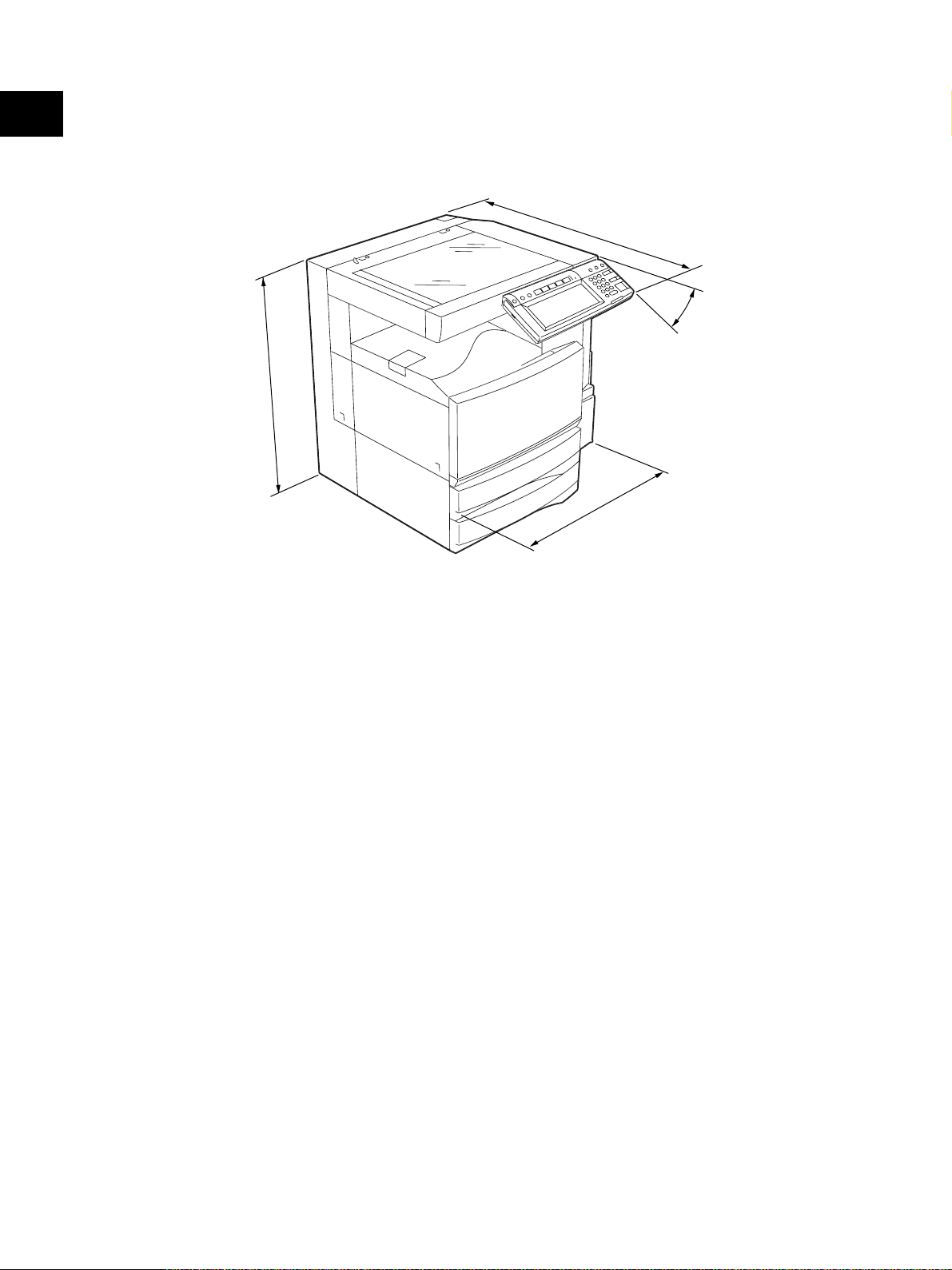
1
• Dimensions of the equipment .......... See the figure below (W660 x D718 x H739 mm)
* When the tilt angle of the control panel is 45 degrees.
7
1
8
45°
9
3
7
660
Fig. 1-101
e-STUDIO3511/4511 SPECIFICATIONS 1 - 4 November 2003 © TOSHIBA TEC
Page 15

1.2 Accessories
Unpacking/Setup instruction 1 set
Operator’s manual 4 pcs. (except for MJD)
Operator's manual pocket 1 pc.
Power cable 1 pc.
Warranty sheet 1 pc. (for NAD)
Setup report 1 set (for NAD and MJD)
Customer satisfaction card 1 pc. (for MJD)
PM sticker 1 pc. (for MJD)
Drum (installed inside of the equipment) 1 pc.
Control panel stopper 1 pc.
Lever 1 pc.
Color developer holder 6 pcs.
Rubber plug 4 pcs.
Blind seal (small / large) 3 pcs. / 1pc.
CD-ROM 4 pcs.
Developer material (Y, M, C, K) 1 pc. each (for TWD)
Screw M3 x 8 / M4 x 8 1 pc. / 1pc.
1
* Machine version
NAD: North America
MJD: Europe
AUD: Australia
ASD: Asia
TWD: Taiwan
SAD: Saudi Arabia
JPD: Japan
November 2003 © TOSHIBA TEC 1 - 5 e-STUDIO3511/4511 SPECIFICATIONS
Page 16

1
1.3 Options
Platen cover KA-3511PC
Reversing Automatic Document Feeder (RADF) MR-3015
Drawer module MY-1021
Paper Feed Pedestal (PFP) KD-1011
Large Capacity Feeder (LCF) KD-1012 A4/LT
Finisher (Hanging type) MJ-1022
Finisher (Console type) MJ-1023, MJ-1024 (with saddle stitcher)
Hole punch unit MJ-6004 N/E/F/S
Staple cartridge STAPLE-1600 (for hanging type)
STAPLE-2000 (for console type)
STAPLE-600 (for saddle stitcher)
Bridge kit KN-3511
Key copy counter, key copy counter socket MU-8, MU-10
Work table KK-3511
Damp heater kit MF-3511
FAX board GD-1150
FAX board 2nd line GD-1160
Expansion memory GC-1180
Wireless LAN adapter GN-1010
PCI slot GO-1030
Scrambler board GP-1030
Notes:
1. The bridge kit (KN-3511) is necessary for installation of the finisher (MJ-1022, MJ-1023 or
MJ-1024).
2. The finisher (MJ-1023 or MJ-1024) is necessary for installation of the hole punch unit
(MJ-6004N/E/F/S).
3. The PCI slot (GO-1030) is necessary for installation of the scrambler board (GP-1030).
1.4 Supplies
Drum PS-OD3511
Toner bag PS-TB3511
Toner cartridge (K) PS-ZT3511 *K, PS-ZT3511K
Toner cartridge (Y) PS-ZT3511 *Y, PS-ZT3511Y
Toner cartridge (M) PS-ZT3511 *M, PS-ZT3511M
Toner cartridge (C) PS-ZT3511 *C, PS-ZT3511C
Marked * : E, D, C and T
e-STUDIO3511/4511 SPECIFICATIONS 1 - 6 November 2003 © TOSHIBA TEC
Page 17

1.5 System List
1
KA-3511PC
Platen cover
(RADF)
MR-3015
Document Feeder
Reversing Automatic
KK-3511
Work table
Damp heater
KN-3511
FAX board
MF-3511
GD-1150
MU8, MU-10
Key copy counter
Bridge kit
GD-1160
FAX board 2nd line
GC-1180
Expansion memory
Wireless LAN adapter
PCI slot
GN-1010
GO-1030
GP-1030
Scrambler board
(LCF)
KD-1012A4/LT
Large Capacity Feeder
(PFP)
KD-1011
Paper Feed Pedestal
MY-1021
Drawer module
Hole punch unit
MJ-6004N/E/F/S
Finisher
MJ-1022
STAPLE-1600
Staple cartridge
November 2003 © TOSHIBA TEC 1 - 7 e-STUDIO3511/4511 SPECIFICATIONS
Finisher
MJ-1023
STAPLE-2000
Staple cartridge
Fig. 1-501
Finisher
MJ-1024
STAPLE-600
Staple cartridge
Page 18

1
e-STUDIO3511/4511 SPECIFICATIONS 1 - 8 November 2003 © TOSHIBA TEC
Page 19
2. OUTLINE OF THE MACHINE
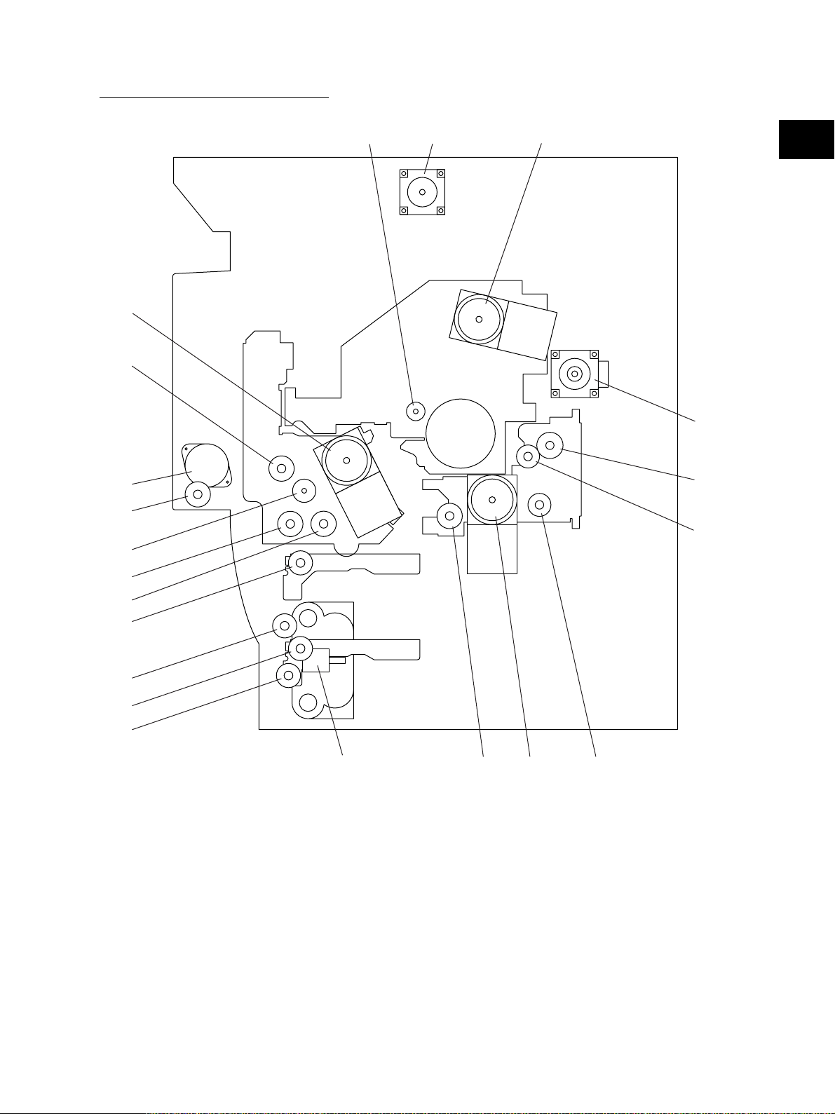
2.1 Sectional View
[A] Front side view
34
5
6
7
33
35
36
28
27
13
42
45
40
37
39
9
41
38
2
32
2
64
60
59
55
62
61
48
11
63
72
50
22
10
16
18
17
19
20
15
21
43
3
44
31
82
30
29
8 1
4
52
14
49
47
51
23
58
53
12
57
56
77
80
78
81
79
73
46
24
26
25
65
68
Fig. 2-101
66
67
69
70
71
76
71
75
74
November 2003 © TOSHIBA TEC 2 - 1 e-STUDIO3511/4511 OUTLINE OF THE MACHINE
04/01
Page 20

1 Original glass
2 RADF original glass
2
3 Exposure lamp
4 Inverter board
5 Mirror-1
6 Mirror-2
7 Mirror-3
8 Carriage-1
9 Carriage-2
10 Lens
11 CCD board
12 SLG board
13 Laser unit
14 Photoconductive drum
15 Main charger
16 Recovery blade
17 Drum cleaning blade
18 Drum cleaner brush
19 Toner recovery auger
20 Discharge LED
21 Drum thermistor
22 Black developer unit
23 Developer sleeve K
24 Mixer-1 (K)
25 Mixer-2 (K)
26 Black auto-toner sensor
27 Revolver unit
28 Revolver home position sensor
29 Developer unit C
30 Developer sleeve C
31 Mixer-F (C)
32 Mixer-R (C)
33 Developer unit M
34 Developer sleeve M
35 Mixer-F (M)
36 Mixer-R (M)
37 Developer unit Y
38 Developer sleeve Y
39 Mixer-F (Y)
40 Mixer-R (Y)
41 Color auto-toner sensor
42 Color toner cartridge sensor
43 Black toner cartridge
44 Color toner cartridge C
45 Color toner cartridge M
46 Color toner cartridge Y
47 Transfer belt
48 Transfer belt drive roller-1
49 Transfer belt drive roller-2
50 Transfer belt tension roller
51 1st transfer roller
52 Transfer belt cleaning blade
53 2nd transfer roller
55 Fuser roller
56 Pressure roller
57 Fuser belt
58 Separation roller
59 Oil roller
60 Cleaning roller
61 Thermistor
62 Thermostat
63 Exit roller
64 IH coil
65 Upper drawer pickup roller
66 Upper drawer feed roller
67 Upper drawer separation roller
68 Lower drawer pickup roller
69 Lower drawer feed roller
70 Lower drawer separation roller
71 Transport roller
72 Registration roller
73 Bypass pickup roller
74 Bypass feed roller
75 Bypass separation roller
76 Bypass transport roller
77 ADU upper transport roller
78 ADU middle transport roller
79 ADU lower transport roller
80 ADU entrance sensor
81 ADU exit sensor
82 Receiving tray
83 Paper clinging detection sensor
e-STUDIO3511/4511 OUTLINE OF THE MACHINE 2 - 2 November 2003 © TOSHIBA TEC
04/01
Page 21
[B] Rear side view (Drive system)
20
21
3
4
5
6
1
2
19
17
18
2
12
11
13
10
8
7
14
Fig. 2-102
16
15
9
November 2003 © TOSHIBA TEC 2 - 3 e-STUDIO3511/4511 OUTLINE OF THE MACHINE
04/05
Page 22

1 Scan motor
2 Main motor
2
3 Drum cleaner brush motor
4 Transport motor
5 Registration clutch
6 Toner motor
7 Upper transport clutch (Low speed)
8 Upper transport clutch (High speed)
9 Black developer drive clutch
10 Lower transport clutch (High speed)
11 Lower transport clutch (Low speed)
12 Upper drawer feed clutch
13 Lower drawer feed clutch
14 Tray-up motor
15 Developer motor
16 Black developer lifting clutch
17 Color developer toner supply clutch
18 Color developer drive clutch
19 Revolver motor
20 ADU motor
21 ADU clutch
e-STUDIO3511/4511 OUTLINE OF THE MACHINE 2 - 4 November 2003 © TOSHIBA TEC
04/05
Page 23
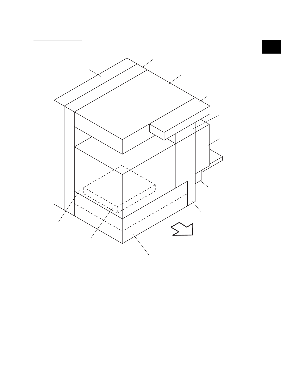
2.2 Electric Parts Layout
[A] Unit construction
PC board unit
2
Drive unit
Scanner unit
Control panel unit
Fuser unit
Automatic
duplexing unit
Process unit
Laser unit
Bypass unit
Transport unit
Front side
Paper feeder unit
Fig. 2-201
November 2003 © TOSHIBA TEC 2 - 5 e-STUDIO3511/4511 OUTLINE OF THE MACHINE
Page 24
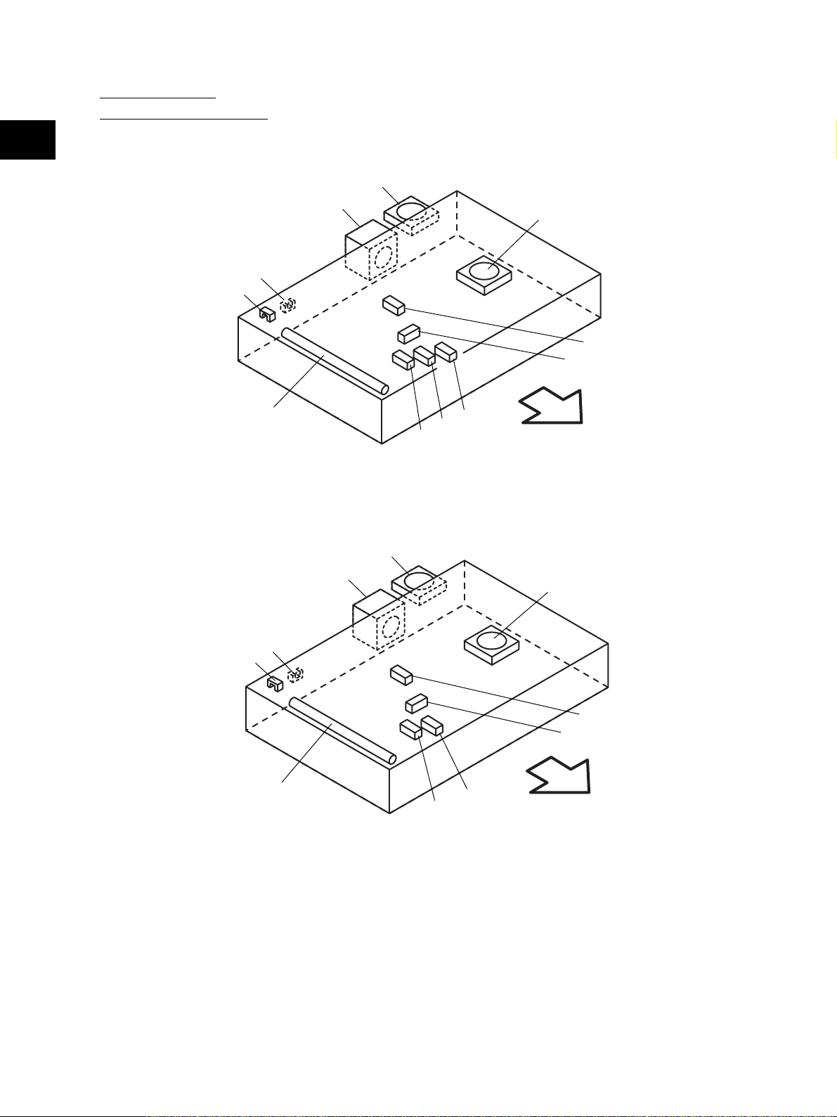
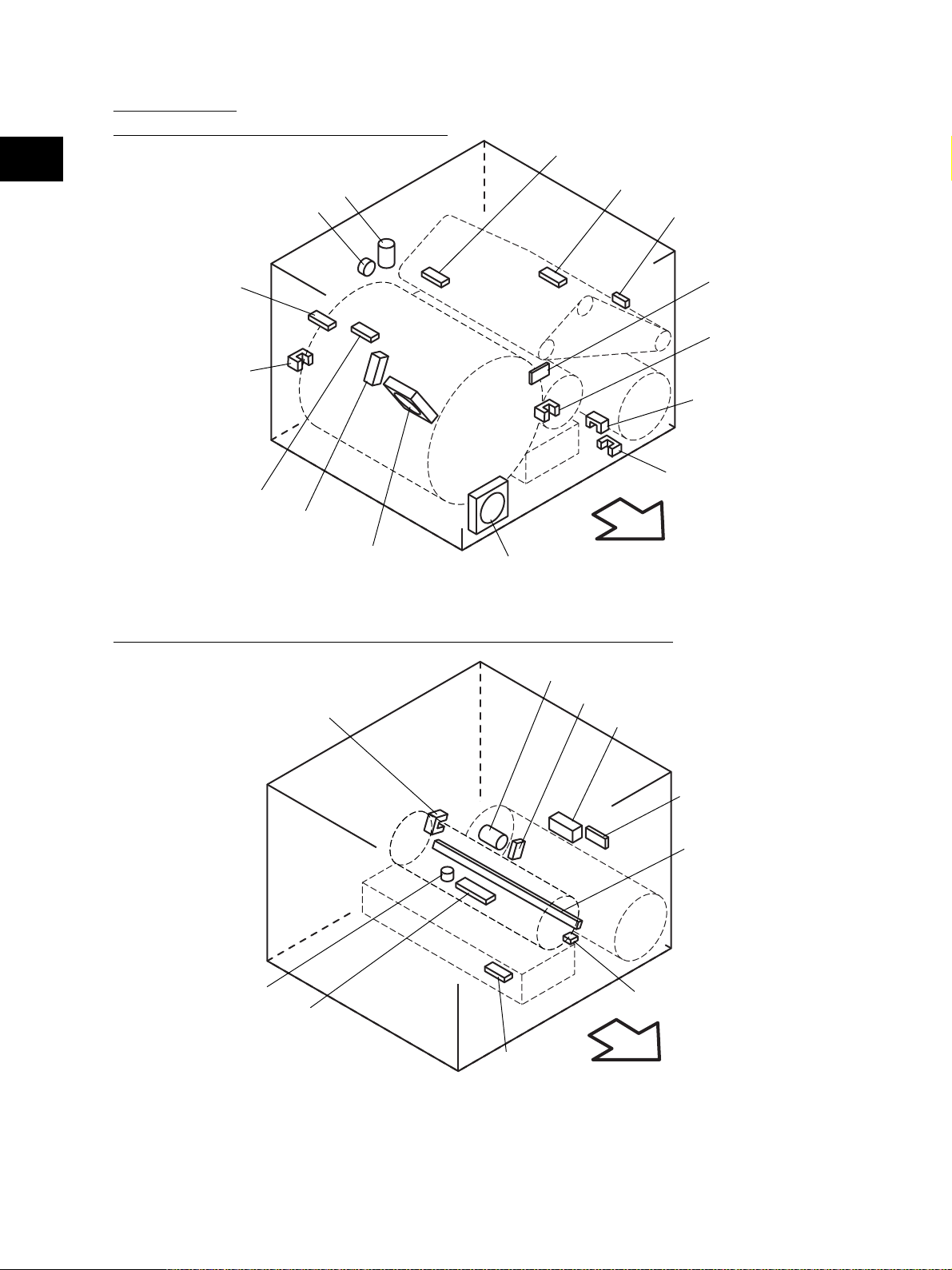
[B] Scanner unit
(B-1) Motor, sensor, lamp
2
A4 series
S6
S7
EXP
M1
M15
S2
S3
Fig. 2-202-1
M14
S5
S4
S1
Front side
LT series
S6
S7
EXP
M1
M15
Fig. 2-202-2
S3
M14
S5
S4
S2
Front side
e-STUDIO3511/4511 OUTLINE OF THE MACHINE 2 - 6 November 2003 © TOSHIBA TEC
Page 25
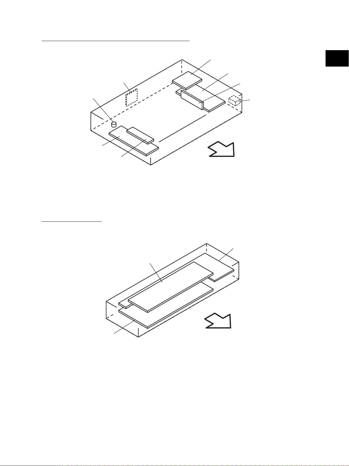
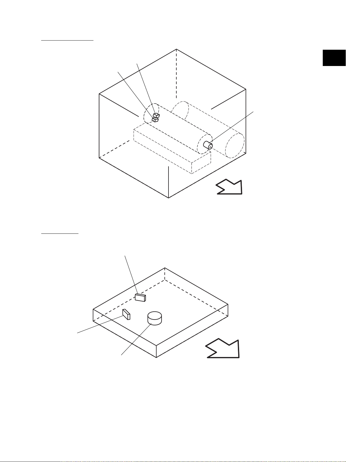
(B-2) Switch, PC board, heater, thermostat, other part
SDV
THMO2*
DH1*
INV
* ASD/AUD/CND/SAD/TWD models: Standard,
NAD/MJD models: Option
[C] Control panel unit
Fig. 2-203
DH2*
2
SLG
CCD
S41
Front side
DSP
KEY
LCD
Front side
Fig. 2-204
November 2003 © TOSHIBA TEC 2 - 7 e-STUDIO3511/4511 OUTLINE OF THE MACHINE
Page 26
[D] Process unit
(D-1) Motor, sensor, switch, clutch, solenoid
2
M2
CLT1
S16
S15
S45
S9
S8
S10
SOL1
M20
M16
Fig. 2-205
Front side
(D-2) Motor, sensor, switch, solenoid, lamp, heater, thermistor, thermostat
M3
S20
S14
SOL2
S19
S21
S12
S11
S17
ERS
THMO3*
DH3*
S13
THM4
Front side
* ASD/AUD/CND/SAD/TWD models: Standard,
NAD/MJD models: Option
Fig. 2-206
e-STUDIO3511/4511 OUTLINE OF THE MACHINE 2 - 8 November 2003 © TOSHIBA TEC
Page 27
(D-3) Motor, switch
S26
S25
2
M13
Front side
Fig. 2-207
[E] Laser unit
LDR
SNS
M4
Front side
Fig. 2-208
November 2003 © TOSHIBA TEC 2 - 9 e-STUDIO3511/4511 OUTLINE OF THE MACHINE
Page 28
[F] Paper feeder unit
CLT2
S33
S31
CLT3
S27
S29
S28
S30
Front side
Fig. 2-209
2
S32
S34
[G] Transport unit
S18
CLT5
S22
S42
S43
S44
S24
S23
Front side
Fig. 2-210
e-STUDIO3511/4511 OUTLINE OF THE MACHINE 2 - 10 November 2003 © TOSHIBA TEC
04/05
Page 29
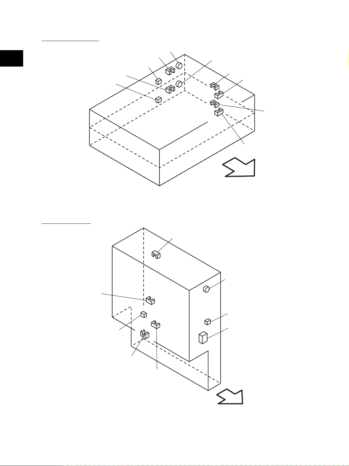
[H] Bypass unit
CLT6
SOL3
[I] Automatic duplexing unit
S35
SFB
2
S36
Front side
Fig. 2-211
S37
ADU
M5
CLT7
S38
S39
Front side
Fig. 2-212
November 2003 © TOSHIBA TEC 2 - 11 e-STUDIO3511/4511 OUTLINE OF THE MACHINE
Page 30
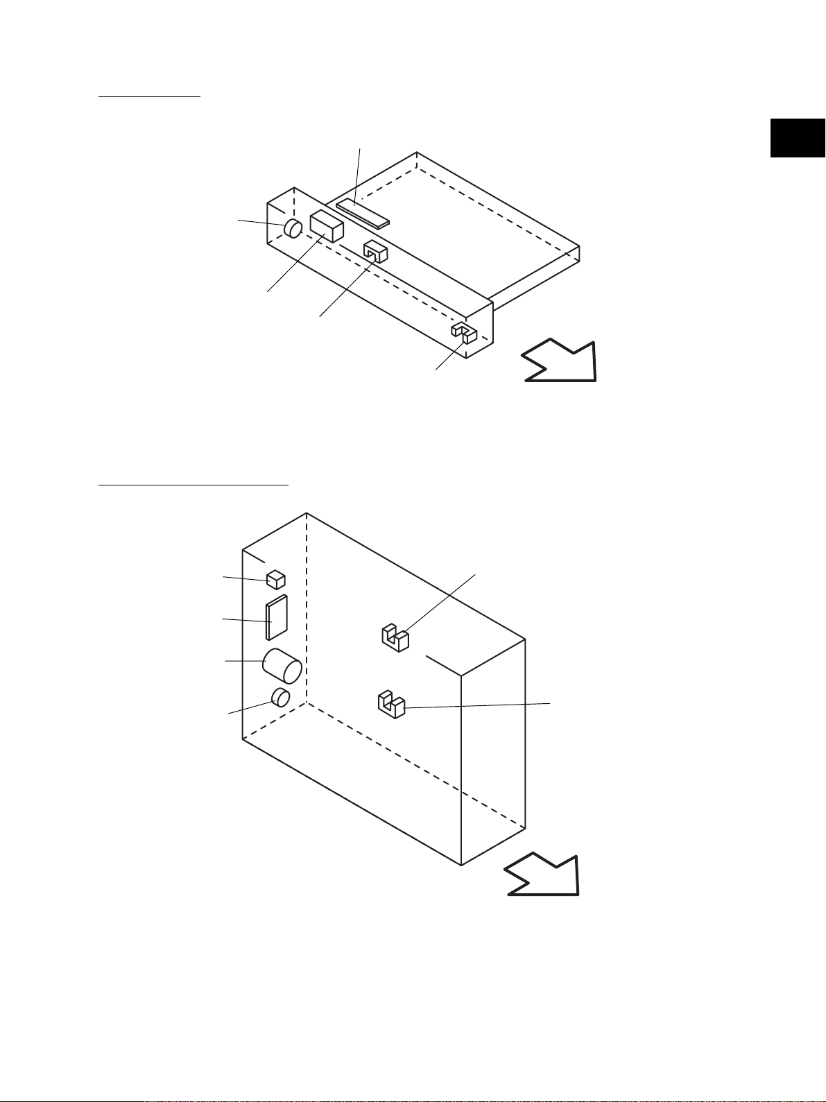
[J] Fuser unit
2
IH-COIL
THMO1
THM2
THM3
THM1
Fig. 2-213
S40
Front side
[K] Drive unit
M17
M6
IH
DRV
M12
CCL
CLT8
CLT9
CLT10
M11
M7
M8
M18
CLT12
M9
CLT14
CLT13
CLT15
CLT16
M10
CLT11
HVT
Front side
Fig. 2-214
e-STUDIO3511/4511 OUTLINE OF THE MACHINE 2 - 12 November 2003 © TOSHIBA TEC
Page 31

[L] PC board unit
LGC
M19
M21
SYS
2
HDD
NIC
NF
BRK
PS
* NAD/SAD/TWD models: FIL (Standard),
ASD/AUD/CND models: FUS (Standard),
MJD model: FUS (Option)
FIL or FUS*
Front side
Fig. 2-215
November 2003 © TOSHIBA TEC 2 - 13 e-STUDIO3511/4511 OUTLINE OF THE MACHINE
05/03
Page 32

2.3 Symbols and Functions of Various Components
The column "P-I" shows the page and item number in the parts list.
2
(1) Motors
Symbol
SCAN-MOT
M1
Scan motor
BELT-CLN-MOT
M2
Transfer belt cleaner auger motor
TNR-MOT
M3
Toner motor
M/DC-POL
M4
Polygonal motor
ADU-MOT
M5
ADU motor
MAIN-MOT
M6
Main motor
EXIT-MOT
M7
Exit motor
DRM-CLN-MOT
M8
Drum cleaner brush motor
TRSP-MOT
M9
Transport motor
M10
M11
M12
M13
M14
M15
M16
M17
M18
M19
M20
M21
TRY-MOT
Tray-up motor
DEV-MOT
Developer motor
REVLV-MOT
Revolver motor
CCL-MOT
Charger cleaner motor
SLG-FAN-MOT
SLG board cooling fan
SCAN-FAN-MOT
Scanner unit cooling fan
LSU-FAN-MOT
Laser unit cooling fan
IH-FAN-MOT
IH control board cooling fan
OZN-FAN-MOT
Ozone exhaust fan
PS-FAN-MOT
Power supply cooling fan
INTRNL-FAN-MOT
Internal cooling fan
HDD-FAN-MOT
HDD cooling fan
Name
Function
Driving the carriages
Driving the transfer belt used toner
auger
Supplying the black toner
Driving the polygonal mirror
Driving the automatic duplexing unit
Driving the drum and transfer belt
Driving the exit roller
Driving the drum cleaner brush and
used toner auger
Driving the fuser unit, 2nd transfer
roller, registration roller, transport
roller and feed roller
Driving the lifting movement of trays
in upper/lower drawer
Driving the black/color developer unit
Driving the lifting movement of the
black developer unit
Supplying the color toner
Driving the transfer belt contact/
release movement
Driving the revolver unit
Driving the main charger wire cleaner
Cooling down the SLG board
Cooling down the scanner unit
Cooling down the laser unit
Cooling down the IH board and SYS
board
Exhausting ozone and cooling down
the equipment inside
Cooling down the power supply unit
Cooling down the equipment inside
Cooling down the HDD
Remarks
B-1
D-1
D-2
E
I
K
K
K
K
K
K
K
B-1
D-3
B-1
D-1
K
K
L
D-1
L
P-I
P17 - I8
P31 - I24
P37 - I16
P10 - I10
P42 - I18
P14 - I6
P6 - I15
P14 - I41
P16 - I26
P4 - I26
P15 - I1
P36 - I11
P28 - I35
P11 - I15
P17 - I27
P5 - I22
P8 - I12
P14 - I49
P7 - I9
P1 - I35
P8 - I50
e-STUDIO3511/4511 OUTLINE OF THE MACHINE 2 - 14 November 2003 © TOSHIBA TEC
05/03
Page 33

(2) Sensors and switches
Symbol
S1-5
S6
S7
S8
S9
S10
S11
S12
S13
S14
S15
S16
S17
S18
S19
S20
S21
S22
S23
S24
Name
APS 1-3, APS-C, APS-R
Automatic original detection sensor
HOME-SNR
Carriage home position sensor
PLTN-SNR
Platen sensor
REVLV-HP-SNR
Revolver home position sensor
COLR-TNR-SNR
Color toner cartridge sensor
COLR-ATTNR-SNR
Color auto-toner sensor
K-DEV-POS-SNR
Black developer contact position detection
sensor
K-DEV-TIM-SNR
Black developer contact timing detection
sensor
K-ATTNR-SNR
Black auto-toner sensor
K-TNR-SW
Black toner cartridge switch
TRBLT-HP-SNR1
Transfer belt home position sensor-1
TRBLT-HP-SNR2
Transfer belt home position sensor-2
TNLVL-SNR
Image quality sensor
TR2-POS-SNR
2nd transfer roller position detection
sensor
TEMP/HUMI-SNR
Temperature/humidity sensor
USD-TNR-FLL-SNR1
Toner bag full detection sensor-1
USD-TNR-FLL-SNR2
Toner bag full detection sensor-2
RGST-SNR
Registration sensor
FED-U-SNR
Upper drawer feed sensor
FED-L-SNR
Lower drawer feed sensor
Function
Original size detection
Carriage home position detection
Opening/closing detection of platen
cover or RADF
Home position detection of the
revolver unit
Detecting the installation fault of color
toner cartridge
Detecting toner density adhered on
the magnetic roller of the color
developer unit
Detecting the black developer
contact position
Detecting the control of ON/OFF
timing of the black developer lifting
clutch
Detecting the density of toner in the
black developer unit
Black toner cartridge presence/
absence detection
Detecting the rotation position of
transfer belt
(for timing of speed switching in thick
paper / OHP film mode)
Detecting the rotation position of
transfer belt
(for timing of the color image data
writing)
Toner amount detection on the
transfer belt
Detecting the 2nd transfer roller
contact position
Detecting the temperature and
humidity inside the equipment
Detecting the used toner is full in the
toner bag
Detecting the presence/absence of
the toner bag
Used toner amount detection in the
toner bag
Detecting the paper transport at the
registration roller section
Detecting paper jam and paper
transport at upper drawer feeding
section
Detecting paper jam and paper
transport at lower drawer feeding
section
Remarks
B-1
B-1
B-1
D-1
D-1
D-1
D-1
D-1
D-2
D-2
D-1
D-1
D-2
G
D-1
D-2
D-1
G
G
G
P-I
S1-4: P11 - I12
S5: P11 - I13
P11 - I17
P17 - I10
P36 - I102
P36 - I104
P36 - I18
P35 - I17
P35 - I17
P34 - I25
P37 - I12
P29 - I23
P30 - I40
P23 - I24
P12 - I5
P5 - I28
P6 - I11
P32 - I108
P23 - I6
P23 - I6
P24 - I52
2
November 2003 © TOSHIBA TEC 2 - 15 e-STUDIO3511/4511 OUTLINE OF THE MACHINE
Page 34

Symbol
S25
2
S26
S27
S28
S29
S30
S31
S32
S33
S34
S35
S36
S37
S38
S39
S40
S41
S42
S43
S44
S45
CCL-F-POS-SW
Charger cleaner front position detection
switch
CCL-R-POS-SW
Charger cleaner rear position detection
switch
CST-U-TRY-SNR
Upper drawer tray-up sensor
CST-L-TRY-SNR
Lower drawer tray-up sensor
EMP-U-SNR
Upper drawer empty sensor
EMP-L-SNR
Lower drawer empty sensor
NEMP-U-SNR
Upper drawer paper stock sensor
NEMP-L-SNR
Lower drawer paper stock sensor
CST-U-SW
Upper drawer detection switch
CST-L-SW
Lower drawer detection switch
SFB-SNR
Bypass paper sensor
SFB-FED-SNR
Bypass feed sensor
ADU-SET-SW
ADU opening/closing switch
ADU-TRU-SNR
ADU entrance sensor
ADU-TRL-SNR
ADU exit sensor
EXIT-SNR
Exit sensor
MAIN-SW
Main switch
FRNT-COV-SW
Front cover opening/closing switch
COV-INTLCK-SW
Cover opening/closing interlock switch
SIDE-COV-SW
Side cover opening/closing switch
CLING-SNR
Paper clinging detection sensor
Name
Function
Detecting the position when the main
charger wire cleaner is moved to the
front side
Detecting the position when the main
charger wire cleaner is moved to the
rear side
Position detection of the lifting tray of
the upper drawer
Position detection of the lifting tray of
the lower drawer
Paper presence/absence detection in
the upper drawer
Paper presence/absence detection in
the lower drawer
Paper amount detection in the upper
drawer
Paper amount detection in the lower
drawer
Detecting presence/absence of the
upper drawer
Detecting presence/absence of the
lower drawer
Detecting presence/absence of paper
on the bypass tray
Detecting the transporting paper fed
from the bypass tray
Automatic duplexing unit opening/
closing detection
Detecting the transporting paper at
automatic duplexing unit entrance
section
Detecting the transporting paper in
automatic duplexing unit
Detecting the transporting paper at
the exit section
Turning ON/OFF of the equipment
Detecting opening/closing of the front
cover
Controlling cutoff and supply of the
24V voltage by opening/closing of the
front cover or jam access cover
Side cover opening/closing detection
Detecting whether the paper is
clinging to the transfer belt or not
D-3
D-3
F
F
F
F
F
F
F
F
H
H
I
I
I
J
B-2
G
G
G
D-1
P-IRemarks
P28 - I103
P28 - I103
P18 - I30
P18 - I30
P18 - I30
P18 - I30
P18 - I30
P18 - I30
P4 - I101
P4 - I101
P22 - I5
P22 - I5
P42 - I43
P42 - I31
P42 - I31
P40 - I32
P11 - I28
P5 - I105
P5 - I15
P24 - I51
P41 - I25
e-STUDIO3511/4511 OUTLINE OF THE MACHINE 2 - 16 November 2003 © TOSHIBA TEC
Page 35

(3) Electromagnetic clutches
Symbol
CLT1
CLT2
CLT3
CLT5
CLT6
CLT7
CLT8
CLT9
CLT10
CLT11
CLT12
CLT13
CLT14
CLT15
CLT16
Name
TRBLT-CLN-CLT
Transfer belt cleaner clutch
CST-U-FEED-CLT
Upper drawer feed clutch
CST-L-FEED-CLT
Lower drawer feed clutch
2TR-CONT-CLT
2nd transfer roller contact clutch
SFB-FEED-CLT
Bypass feed clutch
ADU-CLT
ADU clutch
COLR-DEV-TNR-CLT
Color developer toner supply clutch
COLR-DEV-CLT
Color developer drive clutch
K-DEV-CLT
Black developer drive clutch
K-DEV-LIFT-CLT
Black developer lifting clutch
RGST-CLT
Registration clutch
CST-U-TR-L-CLT
Upper transport clutch (Low speed)
CST-U-TR-H-CLT
Upper transport clutch (High speed)
CST-L-TR-L-CLT
Lower transport clutch (Low speed)
CST-L-TR-H-CLT
Lower transport clutch (High speed)
Function
Driving the transfer belt cleaning
blade contact/release movement
Driving the upper drawer pickup roller
Driving the lower drawer pickup roller
Driving the 2nd transfer roller
contact/release movement
Driving the bypass pickup roller and
bypass feed roller
Driving the automatic duplexing unit
Driving the color developer toner
supply auger
Driving the color developer magnetic
roller
Driving the black developer magnetic
roller
Driving the black developer lifting
cam
Driving the registration roller
Driving the upper transport roller
(Low speed)
Driving the upper transport roller
(High speed)
Driving the lower transport roller
(Low speed)
Driving the lower transport roller
(High speed)
Remarks
D-1
F
F
G
H
I
K
K
K
K
K
K
K
K
K
P-I
P31 - I27
P18 - I29
P18 - I29
P12 - I13
P21 - I20
P42 - I16
P15 - I10
P15 - I32
P15 - I28
P15 - I12
P16 - I29
P16 - I19
P16 - I30
P19 - I20
P19 - I16
2
(4) Solenoids
Symbol
SOL1
SOL2
SOL3
November 2003 © TOSHIBA TEC 2 - 17 e-STUDIO3511/4511 OUTLINE OF THE MACHINE
ATTNR-SHUT-SOL
Color auto-toner sensor shutter solenoid
TNLVL-SHUT-SOL
Image quality sensor shutter solenoid
SFB-SOL
Bypass pickup solenoid
Name
Function
Driving the color auto-toner sensor
shutter
Driving the image quality sensor
shutter
Driving the bypass pickup roller
04/05
Remarks
D-1
D-2
H
P-I
P36 - I25
P23 - I21
P22 - I11
Page 36

(5) PC boards
Symbol
2
CCD
SLG
SDV
DSP
KEY
LDR
SNS
SFB
ADU
IH
DRV
CCL
SYS
LGC
NIC
FIL
FUS
PWA-F-CCD
CCD driving PC board (CCD board)
PWA-F-SLG
Scanning section control PC board
(SLG board)
PWA-F-SDV
Scan motor driving PC board (SDV board)
PWA-F-DSP
Display PC board (DSP board)
PWA-F-KEY
Key control PC board (KEY board)
PWA-F-LDR
Laser driving PC board (LDR board)
PWA-F-SNS
H-sync signal detection PC board
(SNS board)
PWA-F-SFB
Bypass tray slide guide width detection
PC board (SFB board)
PWA-F-ADU
ADU driving PC board (ADU board)
PS-IH
IH control PC board (IH board)
PWA-F-DRV
Driving PC board (DRV board)
PWA-F-CCL
Charger cleaner driving PC board
(CCL board)
PWA-F-SYS
System control PC board (SYS board)
PWA-F-LGC
Logic PC board (LGC board)
PWA-F-NIC
NIC board
PWA-F-FIL
Filter PC board (FIL board)
PWA-F-FUS
Fuse PC board (FUS board)
Name
Function
Controlling CCD and A/D conversion
of image data
Controlling the original scanning
section and RADF
Driving the scan motor
Controlling LCD and the touch panel
on the control panel
Detecting the button entry and
controlling LED on the control panel
Driving the laser diode
Detection of the laser beam position
Detection of the bypass tray slide
guide width
Controlling the automatic duplexing
unit
Controlling each IH coil in the fuser
unit
Controlling each motor and fan in the
system
Driving the charger cleaner motor
Controlling the whole system and
image processing
Controlling the print engine section
Network connection interface
Cutting noise of the AC power
Power supplying to each damp
heater
* NAD/SAD/TWD models: Standard
Power supplying to each damp
heater
* ASD/AUD/CND models: Standard
* MJD model: Option
Remarks
B-2
B-2
B-2
C
C
E
E
H
I
K
K
K
L
L
L
L
L
P-I
P11 - I10
P11 - I38
P17 - I21
P3 - I26
P3 - I25
P10 - I10
P10 - I10
P20 - I13
P42 - I30
P8 - I2
P9 - I8
P9 - I13
P8 - I34
P9 - I7
P8 - I22
P7 - I11
P7 - I4
e-STUDIO3511/4511 OUTLINE OF THE MACHINE 2 - 18 November 2003 © TOSHIBA TEC
Page 37

(6) Lamps and heaters
Symbol
EXP
ERS
IH-COIL
DH1
DH2
DH3
LP-EXPO
Exposure lamp
LP-ERS
Discharge LED
IH-COIL
IH coil
SCN-L-DH
Scanner damp heater (Left)
SCN-R-DH
Scanner damp heater (Right)
DRM-DH
Drum damp heater
Name
(7) Thermistors and thermostats
Symbol
THM1
THM2
THM3
THM4
THMO1
THMO2
THMO3
THMS-EDGE-FBLT
Front edge thermistor
THMS-MAIN-FBLT
Main thermistor
THMS-SUB-FBLT
Sub thermistor
THMS-DRM
Drum thermistor
THERMO-FSR
Fuser thermostat
THERMO-SCN-DH
Scanner damp heater thermostat
THERMO-DRM-DH
Drum damp heater thermostat
Name
Function
Exposing the original to the light
Removing the residual charge from
the drum surface
Heating the fuser roller
Preventing condensation of the
mirrors of the carriages
* ASD/AUD/CND/SAD/TWD models:
Standard
* NAD/MJD models: Option
Preventing condensation of the lens
* ASD/AUD/CND/SAD/TWD models:
Standard
* NAD/MJD models: Option
Preventing condensation of the drum
* ASD/AUD/CND/SAD/TWD models:
Standard
* NAD/MJD models: Option
Function
Detecting the surface temperature at
the edge of the front side of the fuser
belt (for preventing overheating at the
edge of the fuser belt)
Detecting the surface temperature at
the fuser belt center (for controlling
the center IH coil)
Detecting the surface temperature at
the front side of the fuser belt (for
controlling the side IH coil)
Detecting the temperature at the
drum surface
Preventing overheating in the fuser
unit
Controlling the temperature of the
scanner damp heater
* ASD/AUD/CND/SAD/TWD models:
Standard
* NAD/MJD models: Option
Controlling the temperature of the
drum damp heater
* ASD/AUD/CND/SAD/TWD models:
Standard
* NAD/MJD models: Option
Remarks
B-1
D-2
J
B-2
B-2
D-2
Remarks
J
J
J
D-2
J
B-2
D-2
P-I
P26 - I6
P28 - I12
P41 - I7
P11 - I22
P11 - I32
P35 - I23
P-I
P41 - I15
P41 - I15
P41 - I15
P32 - I13
P41 - I12
P11 - I22
P35 - I24
2
November 2003 © TOSHIBA TEC 2 - 19 e-STUDIO3511/4511 OUTLINE OF THE MACHINE
Page 38

(8) Transformer
Symbol
2
HVT
PS-HVT
High-voltage transformer
Name
Function
Generating high-voltage and supplying
it to the following sections
• Main charger wire
• Main charger grid
• Developer bias (color and black)
• Transfer bias (1st and 2nd transfer)
Remarks
K
P-I
P7 - I10
(9) Others
Symbol
INV
LCD
HDD
PS
NF
BRK
INV-EXP
Inverter board
LCD
LCD panel
HDD
Hard disk
PS-ACC
Switching power supply
NS-FILTER
Noise filter
BREAKER
Breaker
Name
Function
Controlling the exposure lamp
Displaying and entering each
information
Storing the program data and image
data
Generating DC voltage and supplying
it to each section of the equipment
Cutting noise of AC power
Preventing the inflow of overcurrent
to the equipment
Remarks
B-2
C
L
L
L
L
P-I
P26 - I7
P3 - I19
P8 - I25
P7 - I9
P7 - I2
P7 - I3
e-STUDIO3511/4511 OUTLINE OF THE MACHINE 2 - 20 November 2003 © TOSHIBA TEC
Page 39

2.4 General Description
2.4.1 System block diagram
SNS
Laser beam
sensor
Laser unit
PWM
LGCSYSSLGCCD
ASIC
)
ASIC
(
Laser diode
LDR
ASIC
2
Finisher
Finisher
Bridge unit
Download jig
8
Bus transceiver
SRAM
ASIC
128KB
512KB
Flash ROM
24MHz
Engine CPU
8
Data-bus
8
RS-232C
32
IPC
Copy key
card
8
Switches
8KB
888
8
16
16
32
NVRAM
I/O
#1
Gate array
Data-bus
#2
Gate array
333MHz
3232
System CPU
64
Data-bus
HVT Clutches Sensors Solenoids
ADU Motors
Bypass
unit
PFP/LCF
Key counter
)
256MB
128MB
:
#1
:
DIMM
(
Main memory
)
DIMM
(
64 64
Main memory
Option
Standard
128MB
Not installed
#0
:
:
Standard
Option
256MB x 1
:
Standard
*Main memory total
128MB x 2
:
Option
: Option
A/D
Amp
)
R
(
Image processing
LVD S
receiver
driver
LVD S
ASIC
A/D
A/D
Amp
Amp
)
)
G/K-odd
B/K-even
(
(
CCD
Battery
RTC
ASIC
)
)
host
(
device
(
Parallel port
USB connector
USB connector
Bus transceiver
SRAM
512KB
32 16
ASIC
)
NIC
IEEE-1284
(
)
LAN connector
10BASE-T/100BASE-TX
(
128MB
256MB
:
:
Standard
Option
RADF
NVRAM
Bus transceiver
Control panel
PCI-bus
Scrambler board
32
ASIC
32
PCI external slot
Scrambler board
HDD
)
DIMM
(
Page memory
Data-bus
16168
8
22MHz
Scanner CPU
512KB
Flash ROM
SRAM
128KB
Download jig
8
Data-bus
256KB
4MB x 2
Flash ROM
2MB x 2
32 32
Flash ROM
16
FAX
)
NCU
LINE-1
(
PSTN
External TEL
NCU
FAX
)
LINE-2
(
PSTN
Download jig
Modem
November 2003 © TOSHIBA TEC 2 - 21 e-STUDIO3511/4511 OUTLINE OF THE MACHINE
Page 40

2.4.2 Construction of boards (a) Construction diagram of boards
2
This system consists of the following including the SYS board as a main board.
NIC
Control panel
KEY
Scanner unit
CCD
DSP
SYS
Laser unit
LDR
SNS
ADU
AC input
FIL
or
FUS
SDV
INV
Main switch
SLG
PS-ACC
Cover opening/closing
interlock switch
DRV
IH
:
DC power supply line
:
AC power supply line
:
Signal line
LGC
SFB
CCL
HVT
(b) Function of each board
CCD board:
This is the board to convert the reflected light by the original to electrical signals. It consists of the
CCD, A/D converter, etc. The CCD converts the reflected light by the original to three-color analog
signal; red, green, blue, and the A/D converter converts each analog signal to digital.
SLG board:
This is the board to mainly control the scanning function (scanner unit) and consists of the ScannerCPU, ASIC, memory (Flash ROM, SRAM), etc. When scanning the original, the exposure lamp and
scan motor are started by the command from the Scanner-CPU. And the image processing is
performed for the image data sent from the CCD by each ASIC.
SDV board:
This is the board on which the driver for driving the scan motor is mounted. The scan motor is started
by the command from the Scanner-CPU.
INV board:
This is the board on which the lighting control circuit of the exposure lamp is mounted. The exposure
lamp lights by the command from the Scanner-CPU.
e-STUDIO3511/4511 OUTLINE OF THE MACHINE 2 - 22 November 2003 © TOSHIBA TEC
Page 41

DSP board:
This is the board to mainly control the control panel. The Panel processing CPU detecting the input
from each button and touch panel, and the lighting control circuit for the backlight of the LCD are
mounted. And it relays the control signal of the control panel from the SYS board to the LCD and
KEY board.
KEY board:
This is the board on which each button switch and each LED on the control panel are mounted.
LDR board:
This is the board on which the laser diode and the ASIC are mounted. The laser is emitted based on
the output image data signal from the ASIC on the LGC board.
SNS board:
This is the board on which the light sensor for detecting the radiating position of the laser is mounted.
It outputs the H-sync signal to the PWM (Pulse Width Modulator) on the LGC board.
SFB board:
This is the board on which the circuit pattern is printed. It detects the position of the slide guide of the
bypass unit.
2
CCL board:
This is the board on which the driver for driving the charger cleaner motor is mounted.
ADU board:
This is the board to relay each signal between the ASIC on the LGC board and the electric parts
(motor, sensor, clutch) in the ADU.
IH board:
This is the board to generate the electric power for driving the IH coil of the fuser unit from the AC
electric power input via the switching power supply. And then it is provided.
DRV board:
This is the board on which the driver for driving the revolver motor, exit motor, and each fan motor are
mounted.
SYS board:
This is the main board taking a leading part in all systems. It consists of the System-CPU, ASIC,
memory (DIMM, Flash ROM, SRAM, NVRAM), RTC (Real Time Clock IC) etc. The System-CPU
controls each ASIC to perform the control of the image processing, image memory (page memory,
main memory, HDD), external interface (RS-232C, IEEE-1284, USB, PCI), NIC, and FAX. And based
on the input data from the control panel, System-CPU communicates with Scanner-CPU on the SLG
board and Engine-CPU on the LGC board, and then issues an operation command to the scanner
and printer engine section.
November 2003 © TOSHIBA TEC 2 - 23 e-STUDIO3511/4511 OUTLINE OF THE MACHINE
Page 42

LGC board:
This is the board to mainly control the print function (printer engine). It consists of the Engine-CPU,
2
ASIC, memory (Flash ROM, SRAM, NVRAM), etc. The Engine-CPU controls each ASIC to drive I/O
(electrical parts) of each section in the system. It leads to the operation of the laser unit, revolver,
developer unit, drum, transfer belt, drawers, bypass unit, ADU, etc. And then the print is made.
NIC board:
This is the interface board to connect this equipment to the LAN environment (10BASE-T, 100BASETX) to communicate with PCs, etc.
FIL board:
This is the board to cut off the noise of AC power from outside, and supply the driving AC power to
the damp heater for condensation prevention of each section (scanner and drum).
FUS board:
This is the board to provide the AC electric power for driving to the damp heater for preventing of the
condensation of each section (scanner and drum).
HVT:
This is the board to generate the DC high voltage from +24V to provide the bias to the section of the
main charger, developer, and transfer.
PS-ACC:
This is the unit to generate each DC voltage, which is used in the equipment, from external AC
electric power input. And then it is provided to each electric part.
e-STUDIO3511/4511 OUTLINE OF THE MACHINE 2 - 24 November 2003 © TOSHIBA TEC
Page 43

2.5 Disassembly and Replacement of Covers and PC boards
2.5.1 Covers
[A] Front cover / Toner bag
(1) Open the front cover.
(2) Remove the toner bag.
2
Fig. 2-501
(3) Pull up 2 hinge pins (on the left and the right)
and then extract them inside.
(4) Take off the front cover.
[B] Receiving tray
(1) Open the front cover ( Chapter 2.5.1 [A]).
(2) Remove 2 screws and pull out the receiving
tray.
Fig. 2-502
Hinge pin
Hinge pin
Fig. 2-503
Receiving
tray
Fig. 2-504
November 2003 © TOSHIBA TEC 2 - 25 e-STUDIO3511/4511 OUTLINE OF THE MACHINE
Page 44

[C] Tray back cover
(1) Remove the receiving tray ( Chapter 2.5.1
2
[B]).
(2) Remove 1 screw and take off the tray back
cover.
Tray back cover
Fig. 2-505
[D] Front lower cover
Black developer unit cover
(1) Take off the front cover ( Chapter 2.5.1 [A]).
(2) Take off the black developer unit cover (
Chapter 12.8 (A-1)).
(3) Release 4 latches and take off the front lower
cover.
[E] Front right cover
(1) Take off the front lower cover ( Chapter 2.5.1
[D]).
(2) Remove 2 screws and take off the front right
cover.
[F] Left cover
(1) Open the front cover ( Chapter 2.5.1 [A]).
(2) Remove 4 screws and take off the left cover.
Latch
Latch
Front lower cover
Fig. 2-506
Front right
cover
Fig. 2-507
Left cover
Fig. 2-508
e-STUDIO3511/4511 OUTLINE OF THE MACHINE 2 - 26 November 2003 © TOSHIBA TEC
Page 45

[G] Left rear cover
(1) Remove 2 screws and take off the left rear
cover.
[H] Left upper cover
(1) Remove 2 screws and take off the left upper
cover.
2
Left rear cover
Fig. 2-509
[I] Front upper cover
(1) Take off the left upper cover ( Chapter 2.5.1
[H]).
(2) Remove 2 screws. Take off the front upper
cover.
[J] Right upper cover
(1) Remove 3 screws and take off the right upper
cover.
Left upper cover
Fig. 2-510
Fig. 2-511
Fig. 2-512
November 2003 © TOSHIBA TEC 2 - 27 e-STUDIO3511/4511 OUTLINE OF THE MACHINE
Page 46

[K] IH terminal cover
Fuser unit cover
2
Caution:
Be sure to unplug before the work, not to get an
Jam access cover
electricshock.
(1) Open the ADU.
(2) Open the jam access cover.
(3) Open the fuser unit cover.
ADU
Fig. 2-513
(4) Remove 2 screws and take off the IH terminal
IH terminal cover
cover.
Fig. 2-514
[L] Right rear cover
(1) Open the ADU.
(2) Take off the IH terminal cover ( Chapter
2.5.1 [K]).
(3) Remove 1 screw and take off the ozone filter
cover.
(4) Remove 2 screws and take off the right upper
cover ( Chapter 2.5.1 [J]).
(5) Remove 2 screws and take off the right rear
cover.
Fig. 2-515
IH terminal cover
Right rear
cover
Ozone filter
cover
Fig. 2-516
e-STUDIO3511/4511 OUTLINE OF THE MACHINE 2 - 28 November 2003 © TOSHIBA TEC
Page 47

[M] Right lower cover
(1) Take off the right rear hinge cover ( Chapter
2.5.1 [N]).
(2) Remove 2 screws and take off the right lower
cover.
[N] Right rear hinge cover
(1) Remove 2 screws and take off the right rear
hinge cover.
2
Right rear
hinge cover
Right lower
cover
Fig. 2-517
[O] Right front hinge cover
(1) Pull out the upper and lower drawers slightly.
(2) Remove 2 screws and take off the right front
hinge cover.
[P] Rear cover
(1) Remove 7 screws and take off the rear cover.
Right rear hinge cover
Fig. 2-518
Right front hinge cover
Fig. 2-519
Rear cover
Fig. 2-520
November 2003 © TOSHIBA TEC 2 - 29 e-STUDIO3511/4511 OUTLINE OF THE MACHINE
Page 48

[Q] Upper rear cover
(1) Take off the ADF or the platen cover.
2
(2) Take off the left upper cover ( Chapter 2.5.1
[H]).
(3) Take off the right upper cover ( Chapter 2.5.1
[J]).
(4) Remove 2 screws and take off the upper rear
cover.
Upper rear cover
Fig. 2-521
e-STUDIO3511/4511 OUTLINE OF THE MACHINE 2 - 30 November 2003 © TOSHIBA TEC
Page 49

2.5.2 PC boards
Note: When the PC board/HDD is replaced, refer to
each CAUTIONS of TROUBLESHOOTHING
in the SERVICE HANDBOOK.
[A] Logic PC board (LGC board)
(A-1) LGC board case
2
(1) Take off the rear cover ( Chapter 2.5.1 [P]).
(2) Loosen 13 screws and take off the LGC
board cover (plate cover).
(3) Disconnect 20 connectors, release 12
harnesses from harness clamps, remove 5
screws and take off the whole LGC board
with the case.
(A-2) LGC board
(1) Take off the rear cover ( Chapter 2.5.1 [P]).
(2) Loosen 13 screws and take off the LGC board
cover (plate cover) ( Chapter 2.5.2 (A-1).
LGC board
cover
Fig. 2-522
LGC board
case
Fig. 2-523
(3) Disconnect 20 connectors.
(4) Remove 4 screws and release 2 locking
supports, take off the LGC board.
Fig. 2-524
[B] Hard disk (HDD)
(1) Take off the rear cover ( Chapter 2.5.1 [P]).
(2) Loosen 4 screws and take off the HVT cover.
HVT cover
Fig. 2-525
November 2003 © TOSHIBA TEC 2 - 31 e-STUDIO3511/4511 OUTLINE OF THE MACHINE
04/05
Page 50

(3) Loosen 9 screws, disconnect 1 connector
and take off the SYS board upper cover.
2
SYS board
upper cover
Fig. 2-526
(4) Loosen 3 screws, disconnect 2 connectors and
take off the SYS board lower cover.
Connector
SYS board
lower
(5) Remove 4 screws and take off the hard disk
from the SYS board lower cover.
[C] System control PC board case
(SYS board case)
(1) Take off the SYS board lower cover
( Chapter 2.5.2 [B]).
(2) Disconnect 5 connectors.
Fig. 2-527
Hard disk
Fig. 2-528
Fig. 2-529
e-STUDIO3511/4511 OUTLINE OF THE MACHINE 2 - 32 November 2003 © TOSHIBA TEC
05/03
Page 51

(3) Remove 4 screws and take off the SYS board
case.
[D] NIC board / System control PC board
(SYS board)
(1) Take off the SYS board lower cover
( Chapter 2.5.2 [B]).
(2) Disconnect 6 connectors.
Fig. 2-530
Harness
clamp
Connector
Harness
clamp
SYS board
case
2
(3) Remove 2 screws, release 1 lock support.
Then take off the NIC board.
(4) Remove 9 screws, release 1 lock support. Then
take off the SYS board.
Fig. 2-531
NIC board
Fig. 2-532
SYS board
Fig. 2-533
November 2003 © TOSHIBA TEC 2 - 33 e-STUDIO3511/4511 OUTLINE OF THE MACHINE
04/05
Page 52

[E] Power supply unit
(1) Take off the rear cover ( Chapter 2.5.1 [P]).
2
(2) Disconnect 8 connectors.
(3) Remove 3 screws and take off the whole
switching power supply unit with the bracket.
Note: Be careful not for the power supply unit to
be caught by harnesses.
Power supply unit
Fig. 2-534
(4) Disconnect 1 connector, remove 4 screws and
take off the power supply cooling fan.
(5) Remove 11 screws and take off the cover of
the power supply unit.
Connector
FLOW
Power supply
cooling fan
Fig. 2-535
Fig. 2-536
[F] High-voltage transformer
(1) Take off the power supply unit
( Chapter 2.5.2 [E]).
(2) Disconnect 8 connectors, remove 2 screws,
release 2 lock supports (white arrow) and
take off the high-voltage transformer.
High-voltage transformer
Fig. 2-537
e-STUDIO3511/4511 OUTLINE OF THE MACHINE 2 - 34 November 2003 © TOSHIBA TEC
04/05
Page 53

[G] Noise filter
(1) Take off the right rear hinge cover and the right
lower cover ( Chapter 2.5.1 [N] [M]).
(2) Disconnect 4 connectors, remove 1 screw
and take off the noise filter.
[H] Fuse board (FUS board)
(1) Take off the right rear hinge cover and the right
lower cover ( Chapter 2.5.1 [N] [M]).
(2) Remove 5 screws to take off the unit and turn it
over.
2
White Black
Fig. 2-538
(3) Disconnect 3 connectors and release 4 lock
supports (white arrow) to take off the fuse
board.
Note: FUS board is not included for MJD and NAD.
Fig. 2-539
Fuse board
Fig. 2-540
November 2003 © TOSHIBA TEC 2 - 35 e-STUDIO3511/4511 OUTLINE OF THE MACHINE
04/05
Page 54

[I] Driving PC board (DRV board)
(1) Take off the LGC board case
2
( Chapter 2.5.2 [A]).
(2) Disconnect 5 connectors, remove 1 screw and
DRV board with the bracket.
DRV board
Fig. 2-541
2.5.3 Options
[A] MR-3015 (Reversing Automatic Document
Feeder (RADF))
(1) Turn OFF the power and unplug the power
cable.
(2) Take off the connector cover.
(3) Disconnect the connector.
(4) Remove 2 screws on the rear side.
Fig. 2-542
Fig. 2-543
Fig. 2-544
e-STUDIO3511/4511 OUTLINE OF THE MACHINE 2 - 36 November 2003 © TOSHIBA TEC
Page 55

(5) Open the RADF.
(6) Remove 2 screws on the front side.
2
Fig. 2-545
(7) Slide the RADF backward and take off by
lifting it up.
Note: When disinstalling the RADF and installing
the platen cover, or disinstalling the platen
cover and installing the RADF, tighten the
screw which installs the damper holding
bracket of the scanner at the following
positions.
Installing the RADF: A
Installing the platen cover: B
Fig. 2-546
Fig. 2-547
A
B
Fig. 2-548
November 2003 © TOSHIBA TEC 2 - 37 e-STUDIO3511/4511 OUTLINE OF THE MACHINE
Page 56

[B] KD-1011 (Paper Feed Pedestal (PFP))
(1) Turn OFF the power and unplug the power
2
cable.
(2) Remove 7 screws and take off the rear cover
of the equipment.
Note: Disconnect the connector of the RADF first
when the RADF is installed.
Fig. 2-549
(3) Remove 1 screw and the ground wire, and then
disconnect 2 connectors (3 if the optional damp
heater is installed).
Connector of optional
damp heater
(4) Remove 2 screws and take off 2 fixing brackets
on the rear side.
(5) Take off the lower drawer of the equipment and
PFP upper drawer.
Fig. 2-550
Fig. 2-551
Fig. 2-552
e-STUDIO3511/4511 OUTLINE OF THE MACHINE 2 - 38 November 2003 © TOSHIBA TEC
Page 57

(6) Remove 4 screws and take off 2 fixing
brackets on the front side.
(7) Lift up the equipment and take off the PFP.
2
Fig. 2-553
[C] KD-1012 (Large Capacity Feeder (LCF))
(1) Turn OFF the power and unplug the power
cable.
(2) Remove 7 screws and take off the rear cover
of the equipment.
Note: Disconnect the connectors of the RADF first
when the RADF is installed.
(3) Remove 1 screw and the ground wire, and then
disconnect 2 connectors (3 if the optional damp
heater is installed).
Fig. 2-554
Fig. 2-555
Connector of optional
damp heater
Fig. 2-556
November 2003 © TOSHIBA TEC 2 - 39 e-STUDIO3511/4511 OUTLINE OF THE MACHINE
Page 58

(4) Remove 2 screws and take off 2 fixing
brackets on the rear side.
2
Fig. 2-557
(5) Take off the lower drawer of the equipment.
(6) Pull out the LCF drawer.
(7) Remove 4 screws and take off 2 fixing brackets
on the front side.
Fig. 2-558
Fig. 2-559
Fig. 2-560
e-STUDIO3511/4511 OUTLINE OF THE MACHINE 2 - 40 November 2003 © TOSHIBA TEC
Page 59

(8) Lift up the equipment and take off the LCF.
[D] MJ-1022 (Hanging finisher)
<When PFP/LCF is not installed>
(1) Turn OFF the power and unplug the power
cable.
(2) Take off the connector cover and disconnect
the connector.
2
Fig. 2-561
(3) Remove 2 screws and take off the safety
bracket on the rear side and the cover.
(4) Remove 2 screws and take off the safety
bracket on the front side and the cover.
Fig. 2-562
Fig. 2-563
Fig. 2-564
November 2003 © TOSHIBA TEC 2 - 41 e-STUDIO3511/4511 OUTLINE OF THE MACHINE
Page 60

(5) Remove 2 screws.
2
Fig. 2-565
(6) Lift up the finisher and take it off.
<When PFP/LCF is installed>
(1) Turn OFF the power and unplug the power
cable.
(2) Take off the connector cover and disconnect
the connector.
(3) Remove 2 screws and take off the cover on
the rear side.
Fig. 2-566
Fig. 2-567
Fig. 2-568
e-STUDIO3511/4511 OUTLINE OF THE MACHINE 2 - 42 November 2003 © TOSHIBA TEC
Page 61

(4) Remove 2 screws and take off the cover on
the front side.
(5) Remove 2 screws.
2
Fig. 2-569
(6) Lift up the finisher and take it off.
Fig. 2-570
Fig. 2-571
November 2003 © TOSHIBA TEC 2 - 43 e-STUDIO3511/4511 OUTLINE OF THE MACHINE
Page 62

[E] MJ-1023 (Console finisher)
(1) Turn OFF the power and unplug the power
2
cable.
(2) Take off the connector cover and disconnect
the connector.
Fig. 2-572
(3) Remove 1 screw and take off the finisher
lower cover.
(4) Remove 3 screws and take off the finisher
front cover.
(5) Remove 1 screw.
Fig. 2-573
Fig. 2-574
Fig. 2-575
e-STUDIO3511/4511 OUTLINE OF THE MACHINE 2 - 44 November 2003 © TOSHIBA TEC
Page 63

(6) Remove 1 screw and take off the cover of the
finisher rear side.
(7) Remove 1 screw.
2
Fig. 2-576
(8) Take off the finisher.
Note: Be careful not to fell the finisher when
moving the finisher unit only.
[F] MJ-1024 (Console finisher)
(1) Turn OFF the power and unplug the power
cable.
(2) Take off the connector cover and disconnect
the connector.
Fig. 2-577
Fig. 2-578
Fig. 2-579
November 2003 © TOSHIBA TEC 2 - 45 e-STUDIO3511/4511 OUTLINE OF THE MACHINE
Page 64

(3) Open the finisher front cover and remove 1
screw.
2
Fig. 2-580
(4) Remove 1 screw and take off the cover of the
finisher rear side.
(5) Remove 1 screw.
(6) Take off the finisher.
Note: Be careful not to fell the finisher when
moving the finisher unit only.
Fig. 2-581
Fig. 2-582
Fig. 2-583
e-STUDIO3511/4511 OUTLINE OF THE MACHINE 2 - 46 November 2003 © TOSHIBA TEC
Page 65

[G] MJ-6004 (Hole punch unit)
(1) Turn OFF the power and unplug the power
cable.
(2) Take off the connector cover and disconnect
connector.
(3) Open the front cover of the hole punch unit
and remove 1 screw.
2
Fig. 2-584
(4) Take off the cover of the punch unit lower
side.
(5) Remove 1 screw.
Fig. 2-585
Fig. 2-586
Fig. 2-587
November 2003 © TOSHIBA TEC 2 - 47 e-STUDIO3511/4511 OUTLINE OF THE MACHINE
Page 66

(6) Remove 3 screws and take off the punch unit
rear cover.
2
Fig. 2-588
(7) Remove 1 screw.
(8) Take off the finisher with the hole punch unit.
Note: Be careful not to fell the finisher when
moving the finisher unit only.
(9) Disconnect 2 connectors.
Fig. 2-589
Fig. 2-590
Fig. 2-591
e-STUDIO3511/4511 OUTLINE OF THE MACHINE 2 - 48 November 2003 © TOSHIBA TEC
Page 67

(10) Remove 2 screws.
(11) Lift up the punch unit and take it off.
2
Fig. 2-592
[H] KN-3511 (Bridge unit)
(1) Turn OFF the power and unplug the power
cable.
(2) Remove 2 screws and take off the cover.
(3) Disconnect 1 connector.
Fig. 2-593
Fig. 2-594
Fig. 2-595
November 2003 © TOSHIBA TEC 2 - 49 e-STUDIO3511/4511 OUTLINE OF THE MACHINE
Page 68

(4) Open the bridge unit. Remove 1 screw and
take off the cover.
2
Fig. 2-596
(5) Close the bridge unit and remove 1 screw.
(6) Remove 4 screws and take off the bracket.
(7) Lift up the bridge unit and release the hook.
Take off the bridge unit toward the front.
Fig. 2-597
Fig. 2-598
Fig. 2-599
e-STUDIO3511/4511 OUTLINE OF THE MACHINE 2 - 50 November 2003 © TOSHIBA TEC
Page 69

3. COPY PROCESS
3.1 Expression of Colors and 4-Step Copy Process
A variety of colors can be expressed by mixing the
three primary colors : Yellow, magenta and cyan.
Red can be created by mixing yellow and magenta;
blue can be created by mixing magenta and cyan;
3
Yellow
green is created by mixing cyan and yellow; and
Red
Green
mixing all the three primary colors allows you to
obtain black.
Magenta
Black
Blue
Cyan
This equipment has accomplished to improve
reproducibility by adding black toner to the mixture
of the above three colors at proper ratio.
[Three primary colors]
Fig. 3-101
e-STUDIO3511/4511 adopts a revolver mechanism which combines the three developer units of yellow,
magenta and cyan. In this process, each image of cyan, magenta and yellow is developed in order by
rotating these developers and overlaid on the transfer belt one after another. Then the black image
developed by independent black developer unit is overlaid for the best expressions of colors. Four layers
of color image (K→ C→ M→ Y) on the transfer belt are transferred onto paper.
1st transfer roller
Transfer belt
Fuser unit
2nd transfer roller
Color developer unit
Laser optical unit
November 2003 © TOSHIBA TEC 3 - 1 e-STUDIO3511/4511 COPY PROCESS
Black developer
unit
Fig. 3-102
Main charger
Photoconductive drum
Page 70

3.2 General Description of Copying Process
2
3
Original exposure
Xenon lamp
16 W
5-2
Color development
Magnetic roller bias
-400V (-100 to -900V) DC
1.0 kV/10kHz AC
3
Data reading (scanning)
CCD
600dpi, 7450 pixels
Image processing
6
1st transfer
1800V (400 to 4000V)
Photoconductive drum
Toner
Carrier
5-1
Black development
Magnetic roller bias
-400V (-100 to -900V) DC
1.2 kV/10kHz AC
Fig. 3-201
9
10
Discharging (LED array)
Wavelength 660nm x 14pcs.
1
Charger (grid voltage)
-600V (-300 to -1200V)
4
Data writing
Semiconductor laser
Pw=4.0 nJ/mm
2
Cleaning
-1000 V
Paper exit
8
Fusing
IH coil
700 to 1300 W
7
2nd transfer
(+)1000V (500 to 4800V)
(-)-1000V (-100 to –2000V)
Bypass feeding
Drawer feeding
PFP/LCF feeding
1. Charging: Places a negative charge on the
surface of the photoconductive drum.
↓
2. Original exposure: Converts images on the
original into optical signals.
↓
3. Data reading: The optical image signals are
read into CCD and converted into electrical
signals.
↓
4. Data writing: The electrical image signals are
changed to light signals (by laser emission)
which expose the surface of the
photoconductive drum.
↓
5. Development: Negatively-charged toner is
made to adhere to the photoconductive drum,
producing a visible image.
↓
6. 1st transfer: Transfers the visible image
(toner) on photoconductive drum to the
transfer belt.
↓
7. 2nd transfer: Transfers the visible image
(toner) on the transfer belt to paper.
↓
8. Fusing: Fuses the toner image to the paper
by applying heat and pressure.
↓
9. Blade cleaning : While scraping off the
residual toner from the drum by the blade,
this blade also eliminates the (+) residual
charge on the drum left after image transfer.
↓
10. Discharging: Eliminates the residual (–)
charge from the surface of the
photoconductive drum.
e-STUDIO3511/4511 COPY PROCESS 3 - 2 November 2003 © TOSHIBA TEC
04/01
Page 71

3.3 Details of Copying Process
(1) Photoconductive drum
The photoconductive drum consists of two layers.
The outer layer is a photoconductive layer made of
an organic photoconductive carrier (OPC), and the
inner layer is an aluminum conductive base in a
cylindrical form.
The photoconductive carrier has a special property:
when it is exposed to light, the electrical resistance
it possesses increases or decreases with the
strength of the light.
Example:
· Strong incident light→
Decreases resistance (works as a conductor.)
· Weak incident light→
Increases resistance (works as an insulator.)
Photoconductive layer
Base
Structure of the photoconductive drum
(Example of OPC)
Fig. 3-301
0
Colored area of original
- 500
Surface potential (V)
3
Time (t)
[Formation of electrostatic latent images]
In the processes of charging, data reading, data
writing, and discharging described below, the areas
on the drum corresponding to colored areas on the
original are deprived of negative charge, while the
areas on the drum corresponding to white areas
retain the negative charge. Thus it forms a negative
charge image on the drum surface.
As this negative charge image on the drum is not
visible to the human eye, it is called an “electrostatic
latent image.”
(2) Charging
Charging is a process to apply charge evenly to
the drum surface.
The charger wire produces negative corona
discharge, which is controlled by the grid so that
White area of original
process
Charging
process
Fig. 3-302
Rotation of drum
- 1000
Discharge
Electric potential of the photoconductive drum
Main charger
the drum surface is evenly charged with negative
potential.
The surface potential on the drum is determined
by the grid potential and is controlled to a fixed value
by the grid control circuit.
November 2003 © TOSHIBA TEC 3 - 3 e-STUDIO3511/4511 COPY PROCESS
Grid control circuit
Fig. 3-303
High-voltage
transformer
Page 72

(3) Data reading (scanning)
Data reading is a process of illuminating the original
with light and converting the reflected light into
electrical signals.
3
The light reflected from the original is directed to
the Charge Coupled Device (CCD) and this optical
image information is converted to electrical signals
CCD board
Scanning section
control PC board
(image signals), which are then transmitted to the
image processing section via the scanner control
PC board.
The CCD for color processing has RGB filters
provided over its surface, which allow the CCD to
read the light amount in the respective ranges of
wavelength. The image data corresponding to the
respective RGB colors is then transmitted to the
image processing section.
(4) Data writing
Data writing is a process of converting the image
signals transmitted from the image processing
section into light signals and exposing the drum
(Example)
CCD light
receiving
amount
Light 255
Dark
Image
processing
section
Image processing
section
Fig. 3-304
Value of image
signals to be
output
0
Laser driving
PC board
Difference between
"light " and "dark" is
divided into 256 steps.
surface with the light signal.
Namely, the image signals transmitted from the
image processing section are converted into optical
signals (laser emission) by the semiconductor laser
element, which are then used to expose the drum
surface, thus forming an electrostatic latent image
there.
e-STUDIO3511/4511 COPY PROCESS 3 - 4 November 2003 © TOSHIBA TEC
Drum
Fig. 3-305
Semiconductor
laser element
Polygonal mirror
Page 73

(5) Development
Development is a process of making the
electrostatic latent images visible to the eye
(visible image).
Developer material is supplied to the
photoconductive drum surface by means of a
magnetic roller, allowing the toner in the
developer material to adhere to the areas on the
drum surface where the potential is lower than
the developer bias which is applied to the
magnetic roller (reverse development).
Magnet
Drum
Magnetic roller
3
Fig. 3-306
Magnetic roller
Bias voltage
-400V (-100 to -900V) DC
1.2kV/10kHz AC
Photoconductive drum
Fig. 3-307
Toner
Carrier (always attracted
onto the magnet)
Toner
Toner
Photoconductive layer
Aluminum base
When the (–) potential of
the photoconductive drum
is higher than the
developer bias.
When the (–) potential of
the photoconductive drum
is lower than the
developer bias.
White background
- 500V
- 400V
- 300V
- 200V
White background
Halftone
Solid
Image is not
developed
Image is developed by
toner
Bias
voltage
- 100V
0
Fig. 3-308
November 2003 © TOSHIBA TEC 3 - 5 e-STUDIO3511/4511 COPY PROCESS
04/01
Page 74

• About developer material
The developer material is comprised of a mixture
of toner and carrier. The toner is charged to a
Coloring agent
(5-10%)
negative polarity and the carrier to a positive
3
polarity, due to the friction with each other
caused by mixing.
Resin (90-95%)
[Toner]
Toner : Mainly consists of resin and coloring.
5-13µm
Ferrite
Carrier: Consists of ferrite, and over its surface
resin coating to provide consistent frictional
electrification.
30-100µm
[Carrier]
Fig. 3-309
Note:
If the developer material is used for a long period
Toner
Carrier
of time (beyond its normal life span), toner will
become caked onto the carrier.
→
The performance of the carrier is lowered.
Result: 1. Image density is lowered.
2. Toner scattering occurs.
3. Background fogging occurs.
Solution: Replace the developer material.
• Magnetic roller
- Magnetic brush development technique -
Inside magnetic rollers, the south and north poles
are arranged as shown in the right figure. The
developer material forms a brush-like fluff which
contacts the photoconductive drum surface.
→
This is caused by the lines of magnetic force
between the south and north poles.
Photoconductive
drum
Where toner is caked, no
frictional electrification
occurs.
Fig. 3-310
Lines of magnetic force
S
N
S
Magnetic roller
Fig. 3-311
e-STUDIO3511/4511 COPY PROCESS 3 - 6 November 2003 © TOSHIBA TEC
Page 75

(6) 1st transfer
• 1st transfer is a process of transcribing the
toner image (visible image) formed on the
photoconductive drum to the transfer belt. A
positive bias is applied to the transfer roller,
causing the transfer belt to be positively
charged. This in turn helps to form an electric
field E between the transfer belt (positive) and
the photoconductive layer of the
photoconductive drum (grounded), thus making
the toner image transferred to the transfer belt.
In the copy process of this equipment, images
are transferred in the order of K→C→M→Y on
Transfer belt
3
Photoconductive drum
Fig. 3-312
1st transfer roller
the transfer belt.
(7) 2nd transfer
• An electrostatic attracting force occurs between
the polarized charge (negative) on the lower
surface of transfer belt and the belt itself (positive).
That makes the toner being absorbed from the
belt to the paper. Then an electric field is formed
between the 2nd transfer roller and the transfer
belt drive roller, which generates a paper
polarization and thus the toner is transferred from
the belt to the paper.
Toner
Transfer belt
E
Photoconductive layer
Aluminum base
Fig. 3-313
Photoconductive
drum
Fig. 3-314
November 2003 © TOSHIBA TEC 3 - 7 e-STUDIO3511/4511 COPY PROCESS
Page 76

(8) Fusing process
Fusing is a process of melting the toner on the
paper and fixing it firmly onto the paper.
Method : The softening point of the toner (main
3
component : resin) is 105 - 1200C.
→→
Fuser belt
Separation
roller
(Heat) Toner is melted by the fuser belt.
+
(Pressure) The fuser belt is pressed against the
Fuser roller
Fig. 3-315
Press roller
pressure roller by the springs to
increase adherence of the melted
toner to the paper.
The paper is subjected to the heat
and pressure when passing through
the fuser belt and the pressure roller.
||
(Fusing) The toner on the paper is fused to it.
(9) Blade cleaning
While eliminating the (+) charge on the
photoconductive drum applied during the transfer
stage, the conductive blade recovers the toner
left on the drum at the same time.
• Elimination of transfer charge
With this OPC photoconductive drum, (+)
charge on their surface cannot be eliminated
optically. Therefore, (–) voltage is applied to the
conductive blade, which is pressed against the
drum, to eliminate the (+) charge applied at the
transfer process.
Surface potential of photoconductive drum
800V
0
± 800V
Transfer Discharge Charging
Elimination of
transfer
charge
Fig. 3-316
e-STUDIO3511/4511 COPY PROCESS 3 - 8 November 2003 © TOSHIBA TEC
Page 77

• Cleaning
The edge of the conductive blade is pressed
against the photoconductive drum surface to scrape
off residual toner. The toner removed is then caught
by the recovery blade.
Recovery blade
3
Drum rotation
(10) Discharging process
Discharging is a process of eliminating the (–) charge
remaining on the photoconductive drum before the next
charging process.
If the charge remaining on the photoconductive drum
is not eliminated, the following phenomenon would
occur:
(–) charge remaining on the photoconductive drum
surface causes uneven application of the charge for
the next copying.
→
The next copy obtains a double image. (The preceding
image remains.)
To prevent this :
The entire surface of the photoconductive drum
is flooded with light by the discharge LED array.
→→ →
Conductive blade
Fig. 3-317
Photoconductive
drum
The photoconductive drum becomes electrically
conductive.
All of the (–) charge remaining on the
Discharge LED
array
photoconductive drum is conducted away to
ground (However, (+) charge is eliminated by
the conductive blade as mentioned in (8)).
Fig. 3-318
Preparation for the next copying process is
completed.
November 2003 © TOSHIBA TEC 3 - 9 e-STUDIO3511/4511 COPY PROCESS
Page 78

3.4 List of Copying Process Conditions
Process
1. Photoconductive drum
(1) Sensitivity
3
2. Charging
OD-FC31 (OPC drum)
(1) Sensitized drum (ø30)
Scorotron type
-250 to -1000 V (grid voltage)
(adjusting by image quality control)
FC-210/310
OD-3511 (OPC drum)
(1) Highly sensitized drum (ø90)
Scorotron type
-300 to -1200 V (grid voltage)
(adjusting by image quality control)
e-STUDIO3511/4511
3. Data writing
(1) Light source
(1) Semiconductor laser
(1) Same as FC-210/310
(adjustment not required)
(2) Light amount
4. Image control
(2) 6.0 nJ/mm
2
Image quality control by detecting
(2) 4.0nJ/mm
Same as FC-210/310
2
toner adhesion amount
5. Development
(1) Magnetic roller
(2) Auto-toner detection
(1) One magnetic roller
(2) Magnetic bridge-circuit method
(1) Same as FC-210/310
(2) Black: Magnetic bridge-circuit
method
Color: Optical reflection sensor
method
(3) Toner supply
(3) Toner cartridge replacing
(3) Same as FC-210/310
method
(4) Toner-empty detection
(5) Toner
(4) Density detection method
(5) T-FC31-K (black)
T-FC31E-K (black)
T-FC31-Y (yellow)
T-FC31E-Y (yellow)
T-FC31-M (magenta)
T-FC31E-M (magenta)
T-FC31-C (cyan)
T-FC31E-C (cyan)
(4) Same as FC-210/310
(5) T-3511-K (black)
T-3511*-K (black)
T-3511-Y (yellow)
T-3511*-Y (yellow)
T-3511-M (magenta)
T-3511*-M (magenta)
T-3511-C (cyan)
T-3511*-C (cyan)
(Marked*: E, D, C and T)
(6) Developer material
(7) Developer bias
(6) D-FC31-K (black)
D-FC31-Y (yellow)
D-FC31-M (magenta)
D-FC31-C (cyan)
(7) DC -100 to -700 V (adjusting by
image quality control)
AC 1.2 kV/4 kHz
(6) D-3511-K (black)
D-3511-Y (yellow)
D-3511-M (magenta)
D-3511-C (cyan)
(7) DC -100 to -900 V (adjusting by
image quality control)
Color: AC 1.0 kV/10 kHz
Black: AC 1.2 kV/10 kHz
6. Transfer
Transfer belt method
(1) 1st transfer: Transfer belt
method
(2) 2nd transfer: Transfer roller
method
7. Separation
Separation by electrostatic attraction of the transfer belt
Self-separation by transfer belt and
2nd transfer roller
e-STUDIO3511/4511 COPY PROCESS 3 - 10 November 2003 © TOSHIBA TEC
Page 79

Process FC-210/310 e-STUDIO3511/4511
8. Photoconductive drum cleaning
(1) Method
(2) Recovered toner
(3) Transfer charge removal
9. Transfer belt cleaning
10.Discharge
11.Fusing
(1) Method
(2) Cleaning
(3) Heat roller temperature
(4) Heater
(1) Blade cleaning
(2) Non-reusable
(3) Simultaneous cleaning and
discharging by the conductive
blade
-
LED array (red)
(1) Belt fusing system
• Upper heat roller: Fluorinated
aluminum roller (ø30)
(Lamp rating: 550W)
• Fuser roller: Silicon sponge
roller (ø38)
• Lower heat roller: PFA tube
roller (ø40)
(Lamp rating: 450 W)
• Fuser belt: PFA tube belt (ø70)
(2) Oil roller method
• Oil roller (ø22)
• Cleaning roller (ø21)
(3) ON/OFF control by thermistor
(upper/lower roller independent
temperature control)
(4) Halogen lamp
(1) Same as FC-210/310
(2) Same as FC-210/310
(3) Same as FC-210/310
3
Blade cleaning
(contact/release mechanism)
Same as FC-210/310
(1) Belt fusing system
• Fuser roller : Fluorinated iron
roller (ø40)
(IH coil: 700 -1300W)
• Pressure roller: Silicon sponge
roller (Surface - PFA tube)
• Fuser belt: PFA tube belt (ø60)
• Separation roller: Ceramic
roller (ø20)
(2) Oil roller method
• Oil roller (ø18)
• Cleaning roller (ø16)
(3) ON/OFF control and power
control by thermistor
(4) IH coil
November 2003 © TOSHIBA TEC 3 - 11 e-STUDIO3511/4511 COPY PROCESS
Page 80

3
e-STUDIO3511/4511 COPY PROCESS 3 - 12 November 2003 © TOSHIBA TEC
Page 81

4. GENERAL OPERATION
4.1 Overview of Operation
Operation of equipment Operation during initializing, pre-running and ready
Drawer feed copying by the [START] button
Copying operation Bypass feed copying
Interrupt copying
4.2 Description of Operation
4.2.1 Warming-up
(1) Initialization
• Power ON
• IH coil ON
• Set number “1”, reproduction ratio “100%” and “Wait Warming Up” are displayed.
• Fan motors ON
• Initialization of laser optical system
- The polygonal motor rotates in low speed.
• Initialization of feeding system
- Each drawer tray goes up.
• Pre-running operation is stopped after five seconds.
• Cleaning of transfer belt
- Main motor is turned ON.
• Initialization of revolver motor
- Detects home position.
- Rotates the developer unit to the waiting position and stops rotating.
( - Performs image quality control.)
• Initialization of scanning system
- The carriage moves to the home position.
- The carriage moves to the peak detection position.
- The exposure lamp is turned ON.
- Peak detection (white color is detected by the shading correction plate)
- The exposure lamp is turned OFF.
• “READY (WARMING UP)” is displayed.
*1
4
(2) Pre-running operation
Pre-running operation is started when the temperature of the fuser belt surface reaches a certain
temperature.
• Transport motor is turned ON.
- Fuser roller rotation.
(3) When the temperature of the fuser belt surface becomes sufficient for fusing,
• “READY” is displayed.
*1: Image quality control should be performed only at change of environment or periodical
performing timing.
November 2003 © TOSHIBA TEC 4 - 1 e-STUDIO3511/4511 GENERAL OPERATION
Page 82

4.2.2 Ready (ready for copying)
• Buttons on the control panel enabled
• When no button is pressed for a certain period of time,
- Set number “1” and reproduction ratio “100%” are displayed. Equipment returns to the normal
ready state.
4
4.2.3 Drawer feed copying (Upper drawer paper feeding)
(1) Press the [START] button ON
• “READY” changes to “COPYING”
• Exposure lamp turned ON
• Scan motor turned ON → Carriages-1 and -2 move forward
• Main motor, transport motor, developer motor and exit motor turned ON
- Drum, fuser unit, developer unit and exit roller are driven
• Drum cleaner brush motor turned ON
(2) Drawer paper feeding
• Fans rotated in high speed and upper drawer feed clutch turned ON
- Pickup roller, feed roller, separation roller and transport roller start to rotate
• Paper reaches the upper drawer feed sensor
-Upper drawer feed sensor is turned ON
• Paper reaches the registration roller
- Registration sensor is turned ON and aligning is performed
• Upper drawer feed clutch is turned OFF after a certain period of time
(3) A certain period of time passed after the carriage operation
• Registration clutch is turned ON after a certain period of time → Paper is transported to the
transfer area
• Copy counter operates
(4) Completion of scanning
• Scan motor turned OFF
• Exposure lamp turned OFF
• Registration clutch turned OFF (after the trailing edge of the paper passed the registration roller)
• “READY (PRINTING)” is displayed
(5) Printing operation
1) Color printing operation
• Black developer lifting clutch, black developer bias (+150), transfer belt cleaner clutch, toner
recovery auger, drum cleaner brush, discharge LED and cleaning blade bias turned ON
• Transfer belt cleaner auger motor turned ON
- Transfer belt used toner auger is driven
• Main charger and 1st transfer bias turned ON
• Transfer belt marker detection
e-STUDIO3511/4511 GENERAL OPERATION 4 - 2 November 2003 © TOSHIBA TEC
Page 83

• Black developer lifting clutch, black developer bias (-) turned ON
- Contact the black developer roller to the drum surface
• Laser emission (black image)
• Black developer drive clutch and black developer bias (AC) turned ON
• 1st transfer (black image)
- Black image is transferred to the transfer belt
• Black developer bias (AC) turned OFF
• Black developer lifting clutch turned ON and black developer drive clutch turned OFF
- Release the black developer roller from the drum surface
• Black developer bias (-) turned OFF
• Revolver motor turned ON
- Revolver rotates 65 degrees to move to cyan developing position
• Transfer belt marker detection
• Laser emission (cyan image)
• Color developer bias (AC) and color developer bias (-) turned ON
• Color developer drive clutch turned ON
• Transfer belt cleaner clutch and transfer belt cleaner auger motor turned OFF
• 1st transfer (cyan image)
- Cyan image is transferred to the transfer belt
• Color developer bias (AC), color developer drive clutch and color developer bias (-) turned OFF
• Revolver motor turned ON
- Revolver rotates 120 degrees to move to magenta developing position
• Transfer belt marker detection
• Laser emission (magenta image)
• Color developer bias (AC), color developer drive clutch and color developer bias (-) turned ON
• 1st transfer (magenta image)
- Magenta image is transferred to the transfer belt
• Color developer bias (AC), color developer drive clutch and color developer bias (-) turned OFF
• Revolver motor turned ON
- Revolver rotates 120 degrees to move to yellow developing position
• Transfer belt marker detection
• Laser emission (yellow image)
• Color developer bias (AC), color developer drive clutch and color developer bias (-) turned ON
• 1st transfer (yellow image)
- Yellow image is transferred to the transfer belt
• Color developer drive clutch, color developer bias (AC) and color developer bias (-) turned OFF
• Revolver motor turned ON
- Revolver rotates 55 degrees to move to escape position
• Transfer belt marker detection
• 2nd transfer roller contact clutch and 2nd transfer bias turned ON
- Contact the 2nd transfer roller to the transfer belt
- The image on the transfer belt is transferred to the paper
• Transfer belt cleaner clutch and transfer belt cleaner auger motor turned ON
• 2nd transfer roller contact clutch and 2nd transfer bias turned OFF
4
November 2003 © TOSHIBA TEC 4 - 3 e-STUDIO3511/4511 GENERAL OPERATION
04/05
Page 84

• Transfer belt cleaner clutch and transfer belt cleaner auger motor turned OFF
• Main charger and 1st transfer bias turned OFF
2) Black printing operation
• Black developer lifting clutch, black developer bias (+150), transfer belt cleaner clutch, toner
recovery auger, drum cleaner brush, discharge LED and cleaning blade bias turned ON
4
• Transfer belt cleaner auger motor turned ON
- Transfer belt used toner auger is driven
• Main charger and 1st transfer bias turned ON
• Black developer lifting clutch and black developer bias (-) turned ON
- Contact the black developer roller to the drum surface
• Laser emission (black image)
• Black developer drive clutch and black developer bias (AC) turned ON
• 1st transfer (black image)
- Black image is transferred to the transfer belt
• 2nd transfer roller contact clutch and 2nd transfer bias turned ON
- Contact the 2nd transfer roller to the transfer belt
- The image on the transfer belt is transferred to the paper
• Black developer bias (AC) turned OFF
• Black developer lifting clutch turned ON and black developer drive clutch turned OFF
- Release the black developer roller from the drum surface
• Black developer bias (-) turned OFF
• Main charger turned OFF
• 2nd transfer roller contact clutch and 2nd transfer bias turned OFF
• Transfer belt cleaner clutch, transfer belt cleaner auger motor and 1st transfer bias turned OFF
(6) Paper exiting
• The exit sensor detects the trailing edge of the paper
• Toner recovery auger, drum cleaner brush, discharge LED and cleaning blade bias turned OFF
• Main motor, transport motor, developer motor and exit motor turned OFF
• Drum cleaner brush motor turned OFF
• Drum, fuser unit and developer unit are stopped
Fans return to rotate at the normal rotation speed
• “READY” is displayed and the equipment enters into ready mode
e-STUDIO3511/4511 GENERAL OPERATION 4 - 4 November 2003 © TOSHIBA TEC
04/05
Page 85

Timing chart for copying (A4/LT size, 1 sheet from upper drawer)
(ms)
0
557
547
1121
801
3100
3162
2885 5610
2740
2840
3089
2885
3104
3741717
5570 8300 11030
8340 110703875
6605 9335 12060
5785
5960 8480 8730 11215 11455 13985 14135
5980 19670
8460
55852885
5435
5435
Scan motor
marker detection
fwd.
Exposure lamp
SVDEN signal
Main motor
Transfer belt
IVSYNC signal
Revolver motor
Transfer belt
cleaner clutch
Color developer
drive clutch
Black developer
lifting clutch
Black developer
drive clutch
rev.
14015
13970114401119087105935
22070
4
2nd transfer roller
contact clutch
2nd transfer bias
Transport motor
Upper drawer feed
Upper drawer feed
Registration sensor
Registration clutch
clutch
sensor
Exit sensor
Scan motor
Exposure lamp
SVDEN signal
Main motor
MVDEN signal
Revolver motor
Transfer belt
cleaner clutch
Color developer
drive clutch
Black developer
lifting clutch
Black developer
drive clutch
fwd.
rev.
(ms)
10
235 570
495
0
543
533
979
660
795 1988
2047710 2632
2300
2020
1989
1962
2160
2160
33602200
3315
1391512755 1784016700
35402470
9020
6355
6500
6345
12880
12685
11460
13725
13380
13680
13745
14790
178401699514040
19670
5ms/ck
2nd transfer roller
contact clutch
2nd transfer bias
Transport motor
Upper drawer feed
Upper drawer feed
Registration sensor
Registration clutch
clutch
sensor
Exit sensor
235
2195
3355
2460
3535 4100
10
575
495 4610
660
3915
3975
4975
7190
7190
9020
4905
4970
6025
5ms/ck
November 2003 © TOSHIBA TEC 4 - 5 e-STUDIO3511/4511 GENERAL OPERATION
Page 86

4.2.4 Bypass feed copying
(1) Insert a paper into the bypass tray.
• Bypass paper sensor is turned ON.
- “Ready for bypass feeding” is displayed.
• Carriages move to the home position.
4
(2) Press the [START] button ON
• “Ready for bypass feeding” changes to “COPYING”.
• Exposure lamp ON
• Scan motor ON → Carriages-1 and -2 move forward.
• Main motor, transport motor, developer motor and exit motor turned ON
- The drum, fuser unit, developer unit and exit roller are driven.
• Drum cleaner brush motor turned ON.
(3) Bypass feeding
• Fans rotate in high speed.
• Bypass feed clutch turned ON.
- The bypass pickup roller is lowered.
- The bypass pickup roller, feed roller and separation roller start to rotate.
• Aligning operation
• Paper reaches the registration roller.
• After a certain period of time, the bypass feed clutch turned OFF.
(4) Hereafter, operations (3) through (6) of “4.2.3. Drawer feed copying” are repeated.
4.2.5 Interruption copying
(1) Press the [INTERRUPT] button
• LED “INTERRUPT” is turned ON.
• Copying operation in progress is temporarily stopped, and the carriages-1 and -2 return to
appropriate positions.
• “Job interrupted job 1 saved” is displayed.
• Automatic density and reproduction ratio 100% are set. Set number remains the same.
(2) Select the desired copy condition
(3) After interruption copying is finished:
• “Press interrupt to resume job 1” is displayed.
• LED “INTERRUPT” is turned OFF by pressing the [INTERRUPT] button, and the equipment
returns to the status before the interruption.
• “Ready to resume job 1” is displayed.
(4) Press the [START] button
The copying operation before the interruption is resumed.
e-STUDIO3511/4511 GENERAL OPERATION 4 - 6 November 2003 © TOSHIBA TEC
Page 87

4.3 Detection of Abnormality
When something abnormal has occurred in the equipment, symbols corresponding to the type of
abnormality are displayed.
4.3.1 Types of abnormality
A) Abnormality cleared without turning OFF the door switch
(1) Add paper
(2) Paper misfeed in bypass
B) Abnormality not cleared without turning OFF the door switch
(1) Misfeed in equipment
(2) Add toner
(3) Developer unit not installed properly
(4) Toner bag replacement
C) Abnormality not cleared without turning OFF the main switch
(1) Call for service
4.3.2 Description of abnormality
A-1) Add paper
[In case of the equipment drawer or PFP drawer] (When drawer is not installed)
Drawer not detected
4
Drawer is not installed:
Drawer is installed but
there is no paper in it:
[In case of the equipment, PFP or LCF drawers] (When drawer is installed)
Based on the combination of the tray-up motor movement and the status of tray-up sensor and
empty sensor, CPU detects the presence of paper.
→
No paper
↓
A signal sent to the control circuit
↓
Drawer area of the illustration blinks
(When the drawer is selected)
↓
[START] button is disabled.
November 2003 © TOSHIBA TEC 4 - 7 e-STUDIO3511/4511 GENERAL OPERATION
Page 88

• When the power is turned ON or LCF drawer is inserted (When the power is turned ON or equip-
ment/PFP drawers are inserted).
LCF performs initialization.
↓
Detects the presence of paper
Tray-up motor ON - The tray goes up
4
At this time, the tray-up sensor and LCF empty sensor are OFF.
→ When the tray-up sensor is not turned ON in a fixed period of time it means that the tray
is in abnormal condition
“Add paper” is displayed regardless of presence/absence of paper
↓
Cleared by turning the power ON/OFF
→ Tray-up sensor is turned ON in a fixed period of time.
- The tray motor stops.
At this time, if the empty sensor is ON - It is judged that there is paper.
OFF - It is judged that there is no paper.
↓
Drawer area of the illustration blinks.
(When the drawer is selected)
• When the paper in the drawer gets short during copying,
→ The tray-up sensor turned OFF
→ The tray-up motor turned ON - Tray goes up
→ Tray-up sensor turned ON
→ Tray-up motor stopped
• Empty sensor turned OFF during the copying in spite of the tray-up sensor is ON
It is judged that there is no paper.
↓
Drawer area of the illustration blinks.
(When the drawer is selected)
↓
The copying operation is stopped.
e-STUDIO3511/4511 GENERAL OPERATION 4 - 8 November 2003 © TOSHIBA TEC
Page 89

A-2) Bypass misfeeding ( )
• During bypass feeding
Bypass feed clutch is turned ON
↓
Registration sensor is turned ON
* Registration sensor is not turned ON in a fixed period of time (E120)
↓
Bypass misfeeding
↓
Bypass misfeed symbol is displayed ( )
↓
The copying operation is disabled.
↓
Solution: The bypass sensor is turned OFF by removing the paper from the bypass tray.
A-3) Set key copy counter
• When the key copy counter (optional) is pulled out from the equipment which installs it: “Set key
copy counter” displayed.
↓
↓
Copying operation disabled
4
• When the counter is pulled out during copying:
Copying is stopped when the key copy counter is pulled out.
B-1) Misfeed in equipment ( )
• Exit sensor detects jamming of the leading edge
of paper
Registration clutch turned ON
↓ Approx 1.2 sec.*
Exit sensor turned ON
If the exit sensor is not turned ON after
approx 1.2 seconds,
↓
Paper jam (E010) → The copying operation is
stopped.
Registration clutch
Exit sensor
Timer
ON
0
Fig. 4-301
ON
Approx 1.2 sec.
Paper jam (E010)
November 2003 © TOSHIBA TEC 4 - 9 e-STUDIO3511/4511 GENERAL OPERATION
Page 90

• Exit sensor detects jamming of the trailing edge of
paper
Registration clutch turned OFF
↓ Approx 1.3 sec*
Registration clutch
OFF
Exit sensor
ON
Exit sensor turned OFF
If the exit sensor is not turned OFF
4
after approx 1.3 seconds,
Timer
Approx 1.3 sec.
↓
Paper jam (E020) → The copying operation is
stopped.
Fig. 4-302
Paper jam (E020)
• Immediately after the power ON
↓
Any of all sensors on paper transport path detects paper (ON)
↓
Paper jam (E030)
• Front cover is opened during copying
↓
Paper jam (E410)
• Registration sensor detects jamming of the leading edge of paper:
The registration sensor is not turned ON in a fixed period of time after the leading edge of paper
passed the transport roller.
↓
Paper jam (E120, E200, E210, E300, E330 and E3C0)
• During paper feeding from ADU:
The registration sensor is not turned ON in a fixed period of time after the ADU clutch is turned
ON.
↓
Paper jam (E110)
• During paper transporting from ADU:
ADU entrance/exit sensors do not detect the paper at the fixed timing
↓
Paper jam (E510 and E520)
• During paper feeding from the equipment or PFP:
The registration sensor is not turned ON in a fixed period of time after the feed clutch is turned
ON.
↓
Paper jam (E220, E310, E320, E340 to E360, E3D0 and E3E0: Error code defers depending on
the paper source.)
e-STUDIO3511/4511 GENERAL OPERATION 4 - 10 November 2003 © TOSHIBA TEC
Page 91

B-2) Add toner ( )
Toner density becomes low
↓
Auto-toner sensor detects the absence of the toner
↓
Control circuit → “Add toner” is displayed: the copying operation disabled
Solution: Open the front cover and replace the toner cartridge with new one.
Toner is supplied → copying operation enabled
B-3) Developer unit not installed properly
Disconnection of the connectors of the developer unit
↓
“Developer unit not installed” is displayed.
Solution: Connect the connectors of the developer unit and close the front cover.
B-4) Toner bag replacement ( )
• Toner bag is full of used toner
↓
Toner recovery auger shifts to the rear side: Toner bag full detection sensor-1 ON
↓
“Dispose of used toner” is displayed
4
• Toner bag full detection sensor is turned ON during printing
↓
Printing is stopped after the paper being printed is exited
Solution: Replace the toner bag with new one and close the front cover.
C-1) Call for service
Error code is displayed instead of the set number by pressing the [CLEAR] button and [8] button
simultaneously when the “Call for service” is blinking.
Refer to the error code table in the Service Handbook.
November 2003 © TOSHIBA TEC 4 - 11 e-STUDIO3511/4511 GENERAL OPERATION
Page 92

4.4 Flow Chart
4.4.1 Power ON to ready
Main switch ON
DC power ON
4
Restart
YES
YES
YES
YES
YES
Paper jam
"E030"
Cover open?
NO
IH coil ON
Fans ON
Registration sensor
ON?
NO
Exit sensor
ON?
NO
ADU
entrance/exit sensor
ON?
NO
Call for service
Upper drawer
feed sensor ON?
NO
Lower drawer
feed sensor ON?
NO
YES
NO
"C260"
Scan motor ON
Home position
detected?
YES
Peak detected?
YES
B
NO
2.5 sec. Elapsed?
YES
Call for service
"C270"
"C280"
Revolver motor ON
Polygonal motor ON
NO
Main motor ON
Color
toner sensor
abnormal?
NO
Revolver
home position
detected?
YES
Revolver
initialization
finished?
YES
Performs image
quality control
YES
Call for service
"CF50"
NO
Call for service
"CEA0"
NO
Image
quality control finished
propery?
YES
A
e-STUDIO3511/4511 GENERAL OPERATION 4 - 12 November 2003 © TOSHIBA TEC
NO
Call for service
"CE10"
"CE20"
"CE40"
"CE50"
"CE90"
Page 93

A
Fuser
belt ready for pre-
running?
YES
Transport motor ON
Tray-up motor ON
NO
B
Fuser belt
reached ready
temp.?
YES
Main motor OFF
Revolver motor OFF
Transport motor OFF
Tray-up motor OFF
IH coil OFF
READY
NO
Thermistor broken?
NO
IH coil broken?
NO
Polygonal
motor condition
abnormal?
NO
IH error?
NO
YES
YES
YES
YES
Call for service
Call for service
Call for service
Call for service
"C410"
"C430"
"C440"
"CA10"
"C470"
"C480"
"C490"
4
November 2003 © TOSHIBA TEC 4 - 13 e-STUDIO3511/4511 GENERAL OPERATION
Page 94

4.4.2 Automatic feed copying
Press [START]
Processing system control
Transport system control Scanner system control
4
Main motor ON
Developer motor ON
Drum cleaner brush motor ON
YES
Polygonal
motor normal
rotation?
YES
Color printed?
YES
C
NO
Call for service
"CA10"
NO
F
Paper jam
"E010"
Transport motor ON
Exit motor ON
Feed clutch ON
Feed clutch OFF
Registration clutch ON
Counter ON/OFF
Registration clutch OFF
NO
NG
Remaining
set number=0?
Exit sensor
check leading
Exit sensor
check trailing
Main motor OFF
Transport motor OFF
Developer motor OFF
Exit motor OFF
YES
edge?
OK
NG
edge?
Exposure lamp ON
Carriage moves forward
Carriage stopped
Exposure lamp OFF
Carriage moves backward
Carriage stopped
Scanner system
control completed
Paper jam
"E020"
READY
e-STUDIO3511/4511 GENERAL OPERATION 4 - 14 November 2003 © TOSHIBA TEC
Page 95

C
D
E
Black developer lifting clutch ON
Black developer bias (+150) ON
Transfer belt cleaner clutch ON
Toner recovery auger ON
Drum cleaner brush ON
Discharge LED ON
Cleaning blade bias ON
Transfer belt cleaner auger motor ON
Main charger ON
1st transfer bias ON
Transfer
belt marker
detected?
YES
Black developer lifting clutch ON
Black developer bias (-) ON
Black
developer position
corrected?
YES
Laser emission (black image)
Black developer drive clutch ON
Black developer bias (AC) ON
NO
Call for service
"CEE0"
NO
Call for service
"CEB0"
Color developer bias (AC) ON
Color developer bias (-) ON
Color developer drive clutch ON
Transfer belt cleaner clutch OFF
Transfer belt cleaner auger motor OFF
1st transfer (cyan image)
Color developer bias (AC) OFF
Color developer drive clutch OFF
Color developer bias (-) OFF
Revolver motor ON
Transfer
belt marker
detected?
YES
Laser emission (magenta image)
Color developer bias (AC) ON
Color developer drive clutch ON
Color developer bias (-) ON
NO
Call for service
"CEE0"
1st transfer (yellow image)
Color developer drive clutch OFF
Color developer bias (AC) OFF
Color developer bias (-) OFF
Revolver motor ON
Transfer
belt marker
detected?
YES
2nd transfer roller contact clutch ON
2nd transfer bias ON
transfer roller position
Transfer belt cleaner clutch ON
Transfer belt cleaner auger motor ON
2nd
corrected?
YES
NO
Call for service
"CEE0"
NO
Call for service
"CEC0"
4
1st transfer (black image)
Black developer bias (AC) OFF
Black developer lifting clutch ON
Black developer drive clutch OFF
Black developer bias (-) OFF
Revolver motor ON
Transfer
belt marker
detected?
YES
Laser emission (cyan image)
D
NO
Call for service
"CEE0"
1st transfer (magenta image)
Color developer bias (AC) OFF
Color developer drive clutch OFF
Color developer bias (-) OFF
Revolver motor ON
Transfer
belt marker
detected?
YES
Laser emission (yellow image)
Color developer bias (AC) ON
Color developer drive clutch ON
Color developer bias (-) ON
E
NO
Call for service
"CEE0"
2nd transfer roller contact clutch OFF
2nd transfer bias OFF
Transfer belt cleaner clutch OFF
Transfer belt cleaner auger motor OFF
Main charger OFF
1st transfer bias OFF
Main motor OFF
Developer motor OFF
Drum cleaner brush motor OFF
Toner recovery auger OFF
Drum cleaner brush OFF
Discharge LED OFF
Cleaning blade bias OFF
Processing system control completed
G
November 2003 © TOSHIBA TEC 4 - 15 e-STUDIO3511/4511 GENERAL OPERATION
04/05
Page 96

F
Black developer lifting clutch ON
Black developer bias (+150) ON
Transfer belt cleaner clutch ON
Toner recovery auger ON
4
Drum cleaner brush ON
Discharge LED ON
Cleaning blade bias ON
Transfer belt cleaner auger motor ON
Main charger ON
1st transfer bias ON
Black developer lifting clutch ON
Black developer bias (-) ON
Black
developer position
corrected?
YES
Laser emission (black image)
Black developer drive clutch ON
Black developer bias (AC) ON
1st transfer (black image)
2nd transfer roller contact clutch ON
2nd transfer bias ON
transfer roller position
Black developer bias (AC) OFF
Black developer lifting clutch ON
Black developer drive clutch OFF
Black developer bias (-) OFF
2nd
corrected?
YES
Main charger OFF
NO
Call for service
"CEB0"
NO
Call for service
"CEC0"
2nd transfer roller contact clutch OFF
2nd transfer bias OFF
Transfer belt cleaner clutch OFF
Transfer belt cleaner auger motor OFF
e-STUDIO3511/4511 GENERAL OPERATION 4 - 16 November 2003 © TOSHIBA TEC
1st transfer bias OFF
G
04/05
Page 97

5. CONTROL PANEL
5.1 Control Panel and Display Panel
The control panel consists of button switches and touch-panel switches to operate equipment and select
various modes, and LEDs and an LCD to display the state of the equipment or the messages.
When the operator’s attention is required, graphic symbols appear with messages explaining the condition
of the equipment in the LCD panel.
This equipment has a movable control panel which enables to adjust its angle to the operator. It also has
improved its operatability and visibility with the enlarged LCD panel.
5
[Control Panel Outside View]
Fig. 5-101
November 2003 © TOSHIBA TEC 5 - 1 e-STUDIO3511/4511 CONTROL PANEL
Page 98

5.2 Items Shown on the Display Panel
5
Fig. 5-201
Fig. 5-202
e-STUDIO3511/4511 CONTROL PANEL 5 - 2 November 2003 © TOSHIBA TEC
Page 99

5.2.1 Display
No. Message State of equipment Note
-
1
Saving energy -
2
press START button
Wait Warming Up
3
Wait Warming Up
4
Auto Start
WAIT
5
Wait adding toner
6
Performing Auto
7
Calibration
READY
8
READY
9
Press START button
to copy
READY
10
(WARMING UP)
READY
11
(PRINTING)
READY
12
(ADDING TONER)
READY
13
(INNER TRAY FULL)
READY
14
(CHECK STAPLER)
READY
15
(CHECK STAPLER)
READY
16
(CHECK SADDLE
STITCH STAPLER)
READY
17
(ADD PAPER)
Press JOB STATUS
button
READY
18
(FINISHER FULL)
READY
19
(HOLE PUNCH
DUST BIN IS FULL)
Power is OFF (at Sleep Mode)
At Energy Saving Mode
Scanner warming up
- Displayed until the equipment becomes
ready to start scanning
Scanner warming up
- Displayed when Auto Start is set
Displayed when performing the controlling
function such as cleaning of 2nd transfer
roller or main charger to keep the equipment
at the best condition
Supplying toner
- Equipment becomes the toner supply state
Displayed at image quality control
Ready for copying
- Waiting for the operation
Copying job interrupted
Scanner warming up
- Ready to scan the original
Printing out the data
- Scanning is enabled
Supplying toner
- Scanning is enabled
Receiving tray in the equipment is full
- Scanning is enabled
No staples in finisher
- Scanning is enabled
Stapling jam occurred in finisher
No staples in saddle stitcher
- Scanning is enabled
No paper in drawer
- Scanning is enabled
Finisher is full of paper
- Scanning is enabled
Punching dust box is full
- Scanning is enabled
Press [START] button or [FUNCTION]
button to clear
Press [START] button to clear
Auto Start can be set
Press [STOP] button to clear the Auto
Start.
Recovers when the toner supply has
finished
Recovers when the image quality
control has finished
Press [START] button to resume
copying or press [MEMORY CLEAR]
button to delete the job
- When the bridge unit is installed
- Resumes printing by removing
papers from the tray
Cleared by supplying the staples
Cleared by supplying staples
Cleared by supplying papers
Resumes printing by removing paper
from the finisher
Resumes printing by removing
punching dust from the dust box
5
November 2003 © TOSHIBA TEC 5 - 3 e-STUDIO3511/4511 CONTROL PANEL
Page 100

No. Message State of equipment Note
20
READY
(SADDLE STITCH
TRAY FULL)
21
READY
(CHANGE DRAWER
TO CORRECT
PAPER SIZE)
Ready for bypass
22
5
feeding
23
COPYING
24
Auto Start
25
Close Large Capacity
Feeder
26
Close Large Capacity
Feeder Door
27
Place Doc. Feeder in
the down position
Insert key copy
28
counter
29
Place originals in the
document feeder
30
Change direction of
original
31
Place last %d
originals in doc.
feeder entrance tray
32
Cannot copy this
original
Add paper
33
34
Cannot duplex this
size
35
Cannot use this
media type
36
Copy size: A4/LT
only
37
Copy size: A4/LT and
A4-R/LT-R
CHANGE DRAWER
38
TO CORRECT
PAPER SIZE
Change drawer to
39
correct media type
Saddle stitcher tray is full of paper
- Scanning is enabled
Incorrect paper size setting
Paper is set on the bypass tray
At the copying state
Auto Start is set during printing
LCF drawer is not installed when feeding
from LCF is set
LCF cover is open when feeding from LCF is
set
RADF is open when original is placed on
RADF
Key copy counter not inserted
Displayed when the conditions are set and
START button is pressed with no original
placed
Displayed when the direction of original
placed is different from the setting
Paper jam occurred during copying (RADF
scanning)
Displayed when the original which is not
allowed to be copied is placed
Displayed when the paper in selected drawer
is running out
Displayed when the paper size which is not
specified for duplex copying is set
Displayed when the paper size which is not
specified for the functions such as stapling or
hole punching is set
Displayed when the paper size which is not
specified for “Book-type duplex copying” or
“Dual-page” is set
Displayed when the paper size which is not
specified for “Rotate Sort”
Displayed when the selected paper size is
not in the drawer
Displayed when the selected media type is
not in the drawer
Cleared by pressing [RESET] button
or [STOP] button
Cleared by installing LCF drawer
Cleared by closing the cover
Cleared by closing RADF
Cleared by inserting key copy
counter
Cleared by setting the original
Not printed out
e-STUDIO3511/4511 CONTROL PANEL 5 - 4 November 2003 © TOSHIBA TEC
 Loading...