

Page 1

MULTIFUNCTIONAL DIGITAL SYSTEMS
e-STUDIO350/450
File No. SME03002800
R03092140700-TTEC
Ver00 2003-11
Page 2

© 2003 TOSHIBA TEC CORPORATION
All rights reserved
Page 3
GENERAL PRECAUTIONS REGARDING THE INSTALLATION
AND SERVICE FOR e-STUDIO350/450
The installation and service should be done by a qualified service technician.
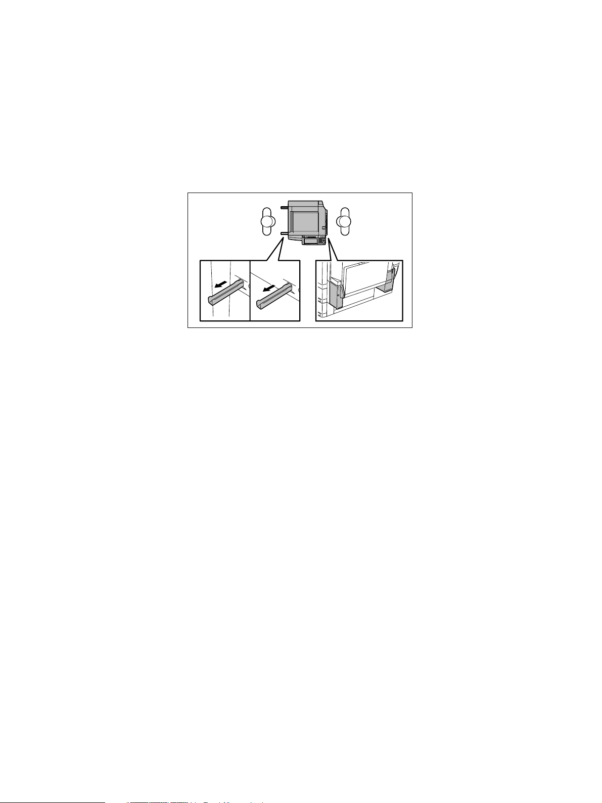
1. Transportation / Installation
• When transporting/installing the equipment, employ two persons and be sure to use the posi
tions as indicated below.
The equipment is quite heavy and weighs approximately 83kg (182.98 lb.) therefore pay full
attention when handling it.
• Be sure not to hold the movable parts or units (e.g. the control panel, ADU or RADF) when
transporting the equipment.
• Be sure to use a dedicated outlet with AC 110V/13.2A, 115V or 127V / 12A, 220-240V or 240V
/ 8A for its power source.
• The equipment must be grounded for safety.
Never ground it to a gas pipe or a water pipe.
• Select a suitable place for installation.
Avoid excessive heat, high humidity, dust, vibration and direct sunlight.
• Also provide proper ventilation as the equipment emits a slight amount of ozone.
• To insure adequate working space for the copying operation, keep a minimum clearance of
80 cm (32”) on the left, 80 cm (32”) on the right and 10 cm (4”) in the rear.
• The socket-outlet shall be installed near the equipment and shall be easily accessible.
2. Service of Machines
• Basically, be sure to turn the main switch off and unplug the power cord during service.
• Be sure not to touch high-temperature sections such as the exposure lamp, the fuser unit, the
damp heater and their periphery.
• Be sure not to touch high-voltage sections such as the chargers, developer, IH control circuit,
high-voltage transformer, exposure lamp control inverter, inverter for the LCD backlight and
power supply unit. Especially, the board of these components should not be touched since the
electric charge may remain in the capacitors, etc. on them even after the power is turned OFF.
• Be sure not to touch rotating/operating sections such as gears, belts, pulleys, fan, etc.
• Be careful when removing the covers since there might be the parts with very sharp edges
underneath.
• When servicing the machines with the power turned ON, be sure not to touch live sections
and rotating/operating sections. Avoid exposure to laser radiation.
Page 4

• Use suitable measuring instruments and tools.
• Avoid exposure to laser radiation during servicing.
- Avoid direct exposure to the beam.
- Do not insert tools, parts, etc. that are reflective into the path of the laser beam.
- Remove all watches, rings, bracelets, etc. that are reflective.
• Unplug the power cable and clean the area around the prongs of the plug once a year or more.
A fire may occur when dust lies on this area.
3. Main Service Parts for Safety
• The breaker, door switch, fuse, thermostat, thermofuse, thermistor, etc. are particularly
important for safety. Be sure to handle/install them properly. If these parts are shorted circuit
and/or made their functions out, they may burn down, for instance, and may result in fatal
accidents. Do not allow a short circuit to occur. Do not use the parts not recommended
by Toshiba TEC Corporation.
4. Cautionary Labels
• During servicing, be sure to check the rating plate and the cautionary labels such as “Unplug
the power cord during service”, “Hot area”, “Laser warning label” etc. to see if there is any dirt
on their surface and whether they are properly stuck to the equipment.
5. Disposition of Consumable Parts, Packing Materials, Used batteries and RAM-ICs
• Regarding the recovery and disposal of the equipment, supplies, consumable parts, packing
materials, used batteries and RAM-ICs including lithium batteries, follow the relevant local
regulations or rules.
6. When parts are disassembled, reassembly is basically the reverse of disassembly unless
otherwise noted in this manual or other related documents. Be careful not to reassemble
small parts such as screws, washers, pins, E-rings, star washers in the wrong places.
7. Basically, the machine should not be operated with any parts removed or disassembled.
8. Precautions Against Static Electricity
• The PC board must be stored in an anti-electrostatic bag and handled carefully using a wrist-
band, because the ICs on it may become damaged due to static electricity.
Caution: Before using the wristband, pull out the power cord plug of the equipment and
make sure that there are no uninsulated charged objects in the vicinity.
Caution : Dispose of used batteries and RAM-ICs including lithium batteries according
to this manual.
Attention : Se débarrasser de batteries et RAM-ICs usés y compris les batteries en lithium
selon ce manuel.
Vorsicht : Entsorgung des gebrauchten Batterien und RAM-ICs (inklusive
der Lithium-Batterie) nach diesem Handbuch.
Page 5

CONTENTS
1. SPECIFICATIONS / ACCESSORIES / OPTIONS / SUPPLIES..................................... 1-1
1.1 Specifications ..................................................................................................................... 1-1
1.2 Accessories ........................................................................................................................ 1-5
1.3 Options ............................................................................................................................... 1-6
1.4 Supplies .............................................................................................................................. 1-6
1.5 System List ......................................................................................................................... 1-7
2. OUTLINE OF THE MACHINE ........................................................................................ 2-1
2.1 Sectional View .................................................................................................................... 2-1
2.2 Electric Parts Layout ........................................................................................................... 2-5
2.3 Symbols and Functions of Various Components .............................................................. 2-14
2.4 General Description .......................................................................................................... 2-21
2.5 Installation and Replacement of Covers and PC boards ................................................... 2-25
2.6 Options ............................................................................................................................. 2-35
3. COPY PROCESS ............................................................................................................3-1
3.1 General Description of Copying Process ............................................................................ 3-1
3.2 Details of Copying Process ................................................................................................. 3-2
3.3 Comparison with DP4500/3500 ........................................................................................ 3-10
4. GENERAL OPERATION ................................................................................................ 4-1
4.1 Overview of Operation ........................................................................................................ 4-1
4.2 Description of Operation ..................................................................................................... 4-1
4.2.1 Warming-up ............................................................................................................. 4-1
4.2.2 Ready state (ready for copying) .............................................................................. 4-2
4.2.3 Drawer feed copying (Upper drawer paper feeding) ................................................ 4-2
4.2.4 Bypass feed copying ................................................................................................ 4-5
4.2.5 Interruption copying ................................................................................................. 4-5
4.3 Detection of Abnormality ..................................................................................................... 4-6
4.3.1 Types of abnormality ................................................................................................ 4-6
4.3.2 Description of abnormality ........................................................................................ 4-7
4.4 Flow Chart ........................................................................................................................ 4-12
4.4.1 Immediately after the power is turned ON ............................................................... 4-12
4.4.2 Automatic paper feed copying ................................................................................ 4-14
5. CONTROL PANEL ......................................................................................................... 5-1
5.1 Control Panel and Display Panel ........................................................................................ 5-1
5.2 Items Shown on the Display Panel ..................................................................................... 5-2
5.2.1 Display..................................................................................................................... 5-3
5.3 Relation between the Equipment State and Operator’s Operation ...................................... 5-8
November 2003 © TOSHIBA TEC i e-STUDIO3511/4511 CONTENTS
Page 6

5.4 Description of Operation ..................................................................................................... 5-9
5.4.1 Dot matrix LCD circuit .............................................................................................. 5-9
5.4.2 LED display circuit ................................................................................................. 5-11
5.5 Disassembly and Replacement ........................................................................................ 5-12
6. SCANNER ..................................................................................................................... 6-1
6.1 Function ............................................................................................................................. 6-1
6.2 Construction ....................................................................................................................... 6-2
6.3 Description of Operation..................................................................................................... 6-4
6.3.1 Scan motor .............................................................................................................. 6-4
6.3.2 Scanning drive circuit .............................................................................................. 6-5
6.3.3 Initialization at power-ON ........................................................................................ 6-7
6.4 Control of Exposure Lamp .................................................................................................. 6-8
6.4.1 General description ................................................................................................. 6-8
6.4.2 Exposure lamp ........................................................................................................ 6-9
6.4.3 Control circuit for the exposure lamp ..................................................................... 6-10
6.5 General Description of CCD Control................................................................................. 6-11
6.5.1 Opto-electronic conversion .................................................................................... 6-11
6.5.2 Shading correction ................................................................................................ 6-11
6.6 Automatic Original Size Detection Circuit ......................................................................... 6-12
6.6.1 Principle of original size detection ......................................................................... 6-12
6.6.2 Process of detection of original size ...................................................................... 6-12
6.7 Disassembly and Replacement ........................................................................................ 6-16
7. IMAGE PROCESSING ................................................................................................... 7-1
7.1 General Description ............................................................................................................ 7-1
7.2 Configuration ...................................................................................................................... 7-3
7.3 SLG Board (PWA-F-SLG-360) ........................................................................................... 7-4
7.3.1 Features .................................................................................................................. 7-4
7.3.2 Functions of image processing circuit ...................................................................... 7-5
7.4 LGC Board (PWA-F-LGC-360) ........................................................................................... 7-9
7.4.1 Features .................................................................................................................. 7-9
7.4.2 Functions of image processing circuit ....................................................................... 7-9
7.5 Laser Driving PC Board .................................................................................................... 7-10
8. LASER OPTICAL UNIT .................................................................................................. 8-1
8.1 General Description ............................................................................................................ 8-1
8.2 Structure ............................................................................................................................. 8-3
8.3 Laser Diode ........................................................................................................................ 8-7
8.4 Laser Optical Unit Cooling Fan ........................................................................................... 8-8
8.5 Polygonal Motor .................................................................................................................. 8-8
8.6 Disassembly and Replacement .......................................................................................... 8-9
e-STUDIO3511/4511 CONTENTS ii November 2003 © TOSHIBA TEC
Page 7

9. PAPER FEEDING SYSTEM ........................................................................................... 9-1
9.1 Functions ............................................................................................................................ 9-1
9.2 Operation ............................................................................................................................ 9-5
9.2.1 Operation of bypass pickup roller ............................................................................ 9-5
9.2.2 Operation of drawer pickup roller ............................................................................ 9-5
9.2.3 Separation of paper ................................................................................................... 9-6
9.2.4 General operation ................................................................................................... 9-7
9.3 Drive Circuit of Tray-up Motor ............................................................................................. 9-9
9.4 Disassembly and Replacement ........................................................................................ 9-10
10. DRIVE SYSTEM .......................................................................................................... 10-1
10.1 General Description ........................................................................................................ 10-1
10.2 Functions ........................................................................................................................ 10-1
10.3 Main Motor...................................................................................................................... 10-2
10.3.1 Main motor drive ................................................................................................... 10-2
10.3.2 Control signals ...................................................................................................... 10-3
10.4 Disassembly and Replacement ....................................................................................... 10-4
11. DRUM RELATED SECTION ....................................................................................... 11-1
11.1 Configuration .................................................................................................................... 11-1
11.2 Functions ......................................................................................................................... 11-2
11.3 Output Control Circuits of High-Voltage Transformer ....................................................... 11-5
11.3.1 Overview .............................................................................................................. 11-5
11.3.2 Description of operations ...................................................................................... 11-5
11.4 Drum Temperature Detection Circuit .............................................................................. 11-7
11.5 Temperature/Humidity Sensor ........................................................................................ 11-8
11.5.1 General description ............................................................................................... 11-8
11.5.2 Construction .......................................................................................................... 11-8
11.6 Disassembly and Replacement ...................................................................................... 11-9
12. DEVELOPMENT SYSTEM ......................................................................................... 12-1
12.1 Configuration ................................................................................................................... 12-1
12.2 Functions ......................................................................................................................... 12-2
12.3 Drive Circuit of Toner Motor ............................................................................................. 12-3
12.4 Auto-Toner Circuit ............................................................................................................ 12-4
12.4.1 General description ............................................................................................... 12-4
12.4.2 Function of auto-toner sensor ............................................................................... 12-5
12.4.3 Adjustment using the temperature / humidity sensor ............................................ 12-7
12.4.4 Adjustment using the drum thermistor .................................................................. 12-7
12.5 Disassembly and Replacement ....................................................................................... 128
13. FUSER UNIT / PAPER EXIT SECTION ...................................................................... 13-1
13.1 General Description .......................................................................................................... 13-1
13.2 Operation ......................................................................................................................... 13-1
13.3 Functions .......................................................................................................................... 13-2
November 2003 © TOSHIBA TEC iii e-STUDIO3511/4511 CONTENTS
Page 8

13.4 Heater Control Circuit ..................................................................................................... 13-4
13.4.1 Configuration ........................................................................................................ 13-4
13.4.2 Heating principle of IH Heater ............................................................................... 13-5
13.4.3 IH control circuit interface .................................................................................... 13-6
13.4.4 Relation between system configuration and IH output .......................................... 13-7
13.4.5 Temperature detection section ............................................................................. 13-8
13.4.6 Abnormality in the IH control circuit .................................................................... 13-13
13.5 Control Circuit of Exit Motor .......................................................................................... 13-15
13.6 Exit Motor Drive ............................................................................................................ 13-15
13.7 Disassembly and Replacement .................................................................................... 13-16
14. AUTOMATIC DUPLEXING UNIT (ADU) .................................................................... 14-1
14.1 General Description ........................................................................................................ 14-1
14.2 Description of Operations ............................................................................................... 14-2
14.3 Drive of ADU................................................................................................................... 14-8
14.4 Flow Chart ...................................................................................................................... 14-9
14.5 Disassembly and Replacement .................................................................................... 14-11
15. POWER SUPPLY UNIT .............................................................................................. 15-1
15.1 Construction ................................................................................................................... 15-1
15.2 Operation of DC Output Circuits ..................................................................................... 15-1
15.3 Output Channel .............................................................................................................. 15-2
15.4 Fuse ............................................................................................................................... 15-4
15.5 Configuration of Power Supply Unit ................................................................................ 15-5
15.6 Sequence of Power Supply............................................................................................. 15-6
15.7 AC Wire Harness ............................................................................................................ 15-7
16. PC BOARDS............................................................................................................... 16-1
e-STUDIO3511/4511 CONTENTS iv November 2003 © TOSHIBA TEC
Page 9
1. SPECIFICATIONS / ACCESSORIES / OPTIONS / SUPPLIES
1.1 Specifications
Values in [ ] are for e-STUDIO450 in case that the specification is different between e-STUDIO350 and
e-STUDIO450.
• Copy process Indirect electrophotographic process (dry)
• Type Desktop type (console type:when paper feed pedestal (PFP) and large capac-
ity feeder (LCF) are installed)
• Original table Fixed type (the left rear corner used as guide to place originals)
• Accepted originals Sheet, book and 3-dimensional object. The reversing automatic document
feeder (RADF) only accepts paper which are not pasted or stapled. (Single-
sided originals: 50 to 127 g/m2/13 to 34lb. Bond, Double-sided originals: 50
to105 g/m2/13 to 28 lb. Bond) Carbon paper are not acceptable either.
Maximum size : A3/LD
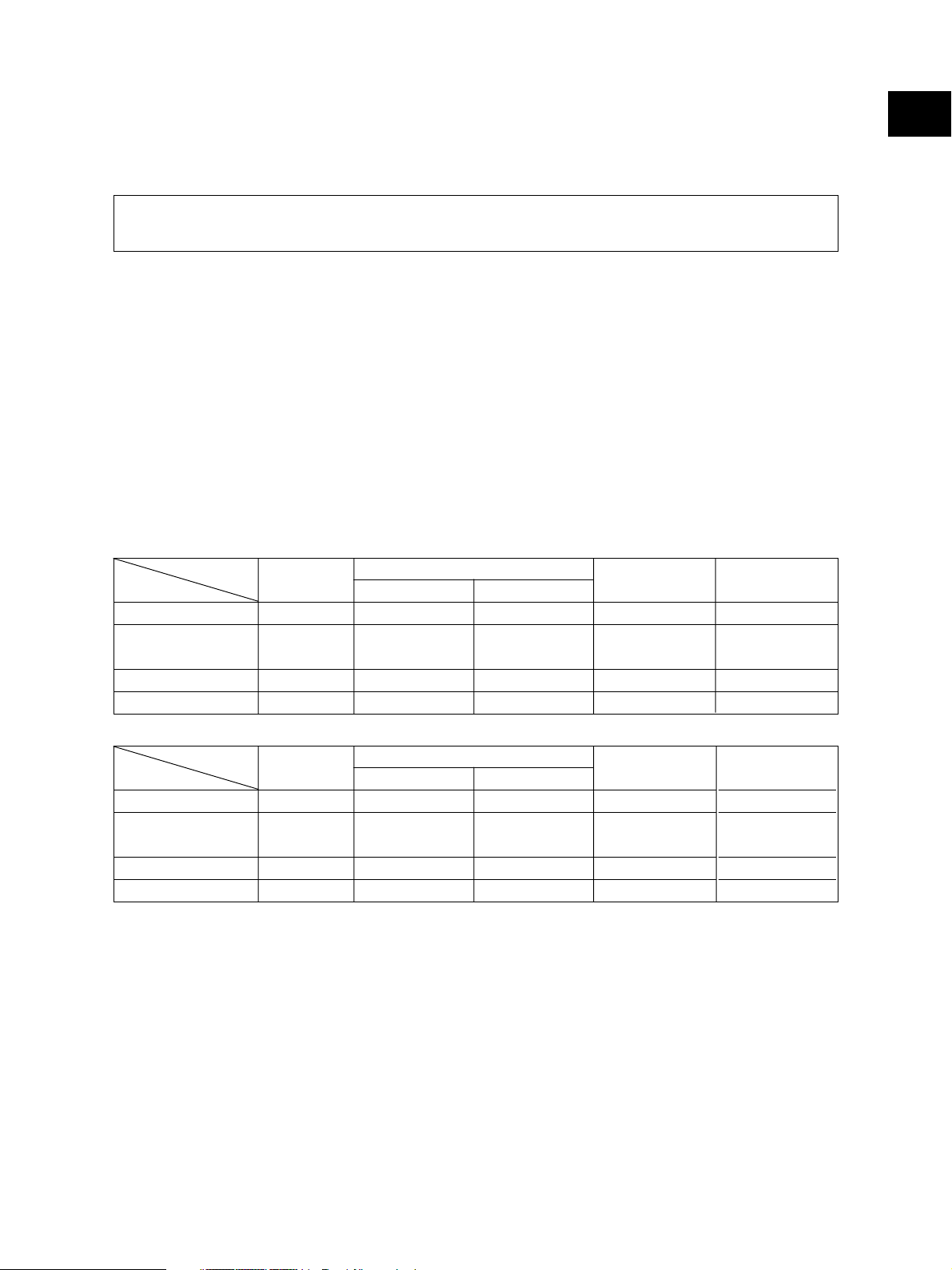
• Copy speed (Copies/min.)
e-STUDIO350
1
Paper supply
Paper size
A4, LT, B5
A4-R, B5-R,
A5-R, LT-R, ST-R
B4, LG
A3, LD
Drawer
35
25
21
18
Size specified
Bypass feed
35
25
21
18
Size not specified
18
18
18
18
PFP
35
25
21
18
LCF
35
–
–
–
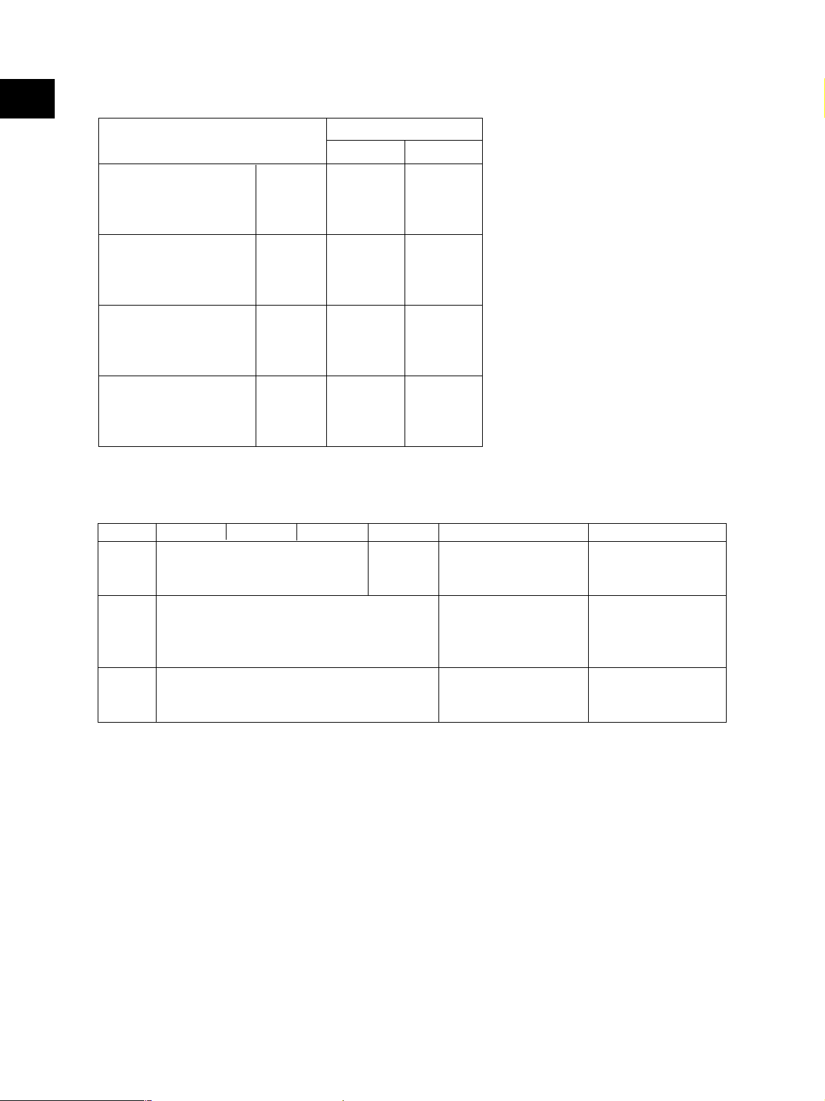
e-STUDIO450
Paper supply
Paper size
A4, LT, B5
A4-R, B5-R,
A5-R, LT-R, ST-R
B4, LG
A3, LD
“–” means “Not acceptable”.
*
The copy speed in the above table are available when originals are manually placed for single side,
*
Drawer
45
28
24
21
Size specified
Bypass feed
40
28
24
21
Size not specified
21
21
21
21
PFP
45
28
24
21
LCF
45
–
–
–
multiple copying.
When the RADF is used, the copy speed of 35[45] sheets per minute is only available under the
*
following conditions:
• Original/Mode: Single side original/A4/LT size. APS/automatic density are not selected.
• Number of sheets: 35[45] or more.
• Paper feeding: LCF
• Reproduction ratio: 100%
November 2003 © TOSHIBA TEC 1 - 1 e-STUDIO350/450 SPECIFICATIONS
Page 10
1
* System copy speed
Copy mode
Single-sided originals
↓
Single-sided copies
Single-sided originals
↓
Double-sided copies
Double-sided originals
↓
Double-sided copies
Double-sided originals
↓
Single-sided copies
• Copy paper
1 set
3 sets
5 sets
1 set
3 sets
5 sets
1 set
3 sets
5 sets
1 set
3 sets
5 sets
Sec.
e-STUDIO350
20.85
57.95
91.20
27.42
62.18
97.55
55.47
126.21
196.93
48.22
117.44
184.96
e-STUDIO450
17.49
46.68
73.50
25.71
57.41
89.03
54.68
118.07
181.36
48.20
102.18
155.06
The system copy speed, including
*
scanning time, is available when 10
sheets of A4/LT size original are
set on RADF and one of the copy
modes in the left table is selected.
The period of time from pressing
[START] to the paper exit com-
pletely out of the equipment based
on the actually measured value.
Upper drawer is selected and
*
copying is at the non-sort mode.
Automatic copy density, APS/AMS
*
are turned off.
Finisher is not installed.
*
Drawer ADU PFP LCF Bypass copy Remarks
Size A3 to A5-R A3 to A5-R,LD to ST-R
LD to ST-R A4, LT (Non-standard or user-
specified sizes can be set.)
Weight
64 to 105 g/m
17 to 28 lb.
Special Tracing paper, labels,
paper – OHP film (thickness: 80 µm
• First copy time ................... e-STUDIO350: Approx. 3.9sec. or less
e-STUDIO450: Approx. 3.9sec. or less
(A4/LT, upper drawer, 100%, original placed manually)
• Warming-up time ............... Approx. 20 seconds (temperature: 20°C)
• Multiple copying ................. Up to 999 copies; Key in set numbers
• Reproduction ratio ............. Actual ratio: 100±0.5%
Zooming: 25 to 400% in increments of 1%
• Resolution/Gradation .........Scanning: 600 dpi x 600 dpi
2
64 to 209 g/m2,17 to 55 lb.
(Continuous feeding)
50 to 209 g/m2, 13 to 55 lb.
(Single paper feeding)
or thicker)
(25 to 200% when using RADF)
These special papers
recommended
by Toshiba Tec
........ Printing: Equivalent to 2400 dpi x 600 dpi
........ Gradation: 256 steps
e-STUDIO350/450 SPECIFICATIONS 1 - 2 November 2003 © TOSHIBA TEC
Page 11

• Eliminated portion ............. Leading edges : 3.0±2.0 mm, Side/trailing edges : 2.0±2.0 mm (copy)
Leading / trailing edges : 5.0±2.0 mm, Side edges : 5.0±2.0 mm (print)
• Paper feeding .................... Automatic feeding : Standard drawers–2 drawers (stack height 60.5
mm, equivalent to 550 sheets; 64 to 80 g/m2 (17 to
22 lb.))
PFP–Option (One drawer or two : stack height
60.5 mm, equivalent to 550 sheets; 64 to 80 g/m
(17 to 22 lb.))
LCF–Option (Stack height 137.5 mm x 2: equivalent
to 2500 sheets; 64 to 80 g/m2 (17 to 22 lb.))
Bypass feeding: (Stack height 11 mm : equivalent to 100 sheets; 64 to
80 g/m2 (17 to 22 lb.))
• Capacity of originals in the reversing automatic document feeder (Option)
................. A3 to A5-R, LD to ST-R : 100 sheets / 80 g/m2 (Stack height 16mm or less)
• Automatic duplexing unit ... Stackless, Switchback type
• Toner supply ...................... Automatic toner density detection/supply
Toner cartridge replacing method
• Density control .................. Automatic density mode and manual density mode selectable in 11 steps
1
2
• Weight ............................... 83 kg, 183 lb
• Power requirements ..........AC 110V (±10%) / 13.2A, 115V (±10%) or 127V (±10%) / 12A
220-240V (±10%) or 240V (±10%) / 8A
• Power consumption ........... 1.5 kW or less (115V series, 200V series)
The electric power is supplied to the RADF, Finisher, Job Separator, Offset Tray, PFP and LCF
*
through the equipment.
• Total counter ...................... Electronical counter
November 2003 © TOSHIBA TEC 1 - 3 e-STUDIO350/450 SPECIFICATIONS
Page 12
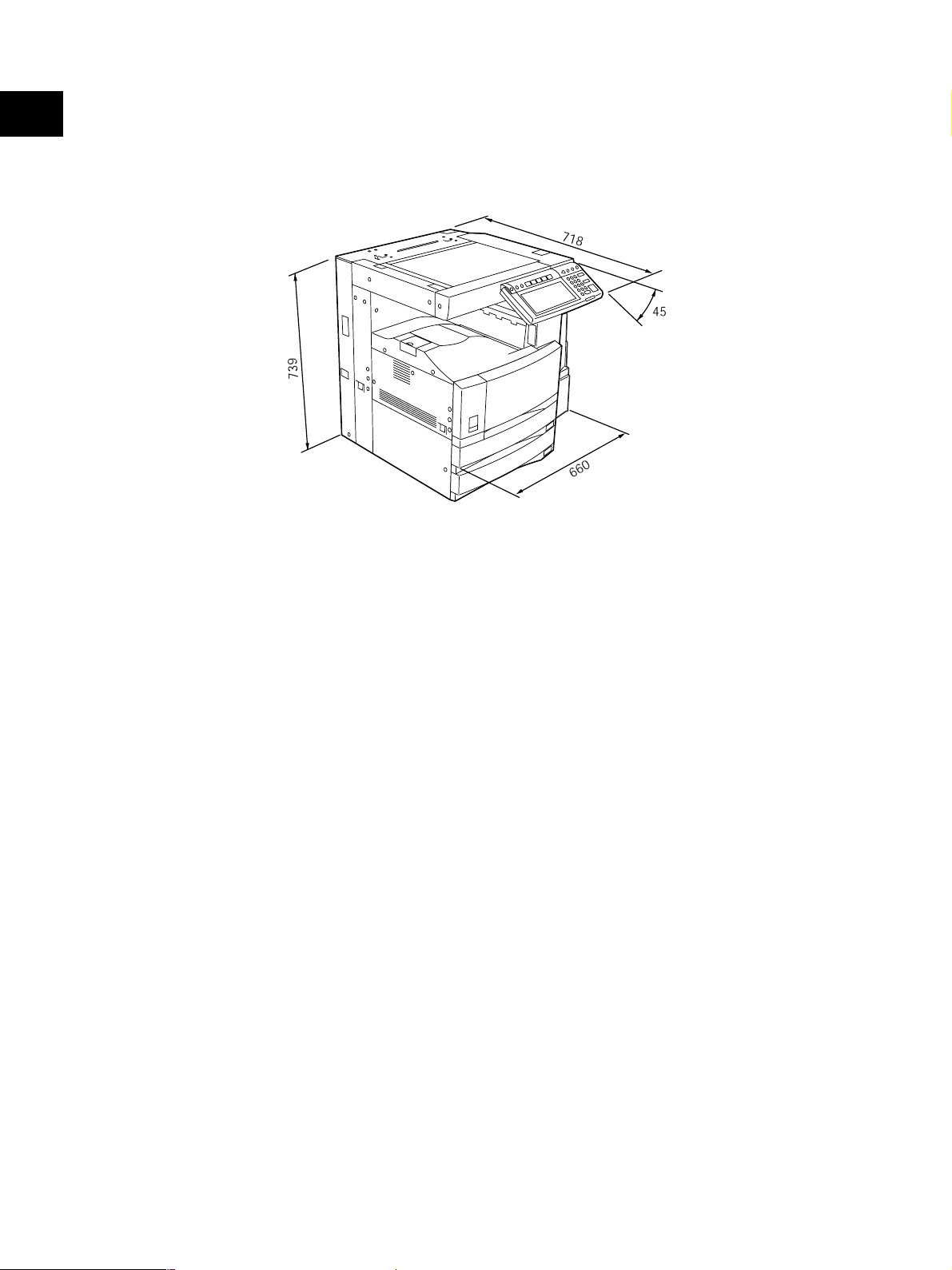
1
• Dimensions of the equipment ...... See the figure below (W660 x D718 x H739 mm)
* When the tilt angle of the control panel is 45 degrees.
Fig. 1-101
e-STUDIO350/450 SPECIFICATIONS 1 - 4 November 2003 © TOSHIBA TEC
Page 13

1.2 Accessories
Unpacking/setup instruction 1 set
Operator’s manual 4 pcs. (except for MJD)
Operator's manual pocket 1 pc.
Power cable 1 pc.
Warranty sheet 1 pc. (for NAD)
Setup report 1 set (for NAD and MJD)
Customer satisfaction card 1 pc. (for MJD)
PM sticker 1 pc. (for MJD)
Drum (installed inside of the equipment) 1 pc.
Toner bag 1 pc.
Toner cartridge 1 pc. (except for NAD,MJD)
Developer material 1 pc. (except for NAD,MJD)
Operation panel stopper 1 pc.
Blind seal 4 pcs.
Rubber plug 4 pcs.
CD-ROM 5 pcs.
1
* Machine version
NAD: North America
MJD: Europe
AUD: Australia
ASD: Asia
TWD: Taiwan
SAD: Saudi Arabia
JPD: Japan
CND: China
November 2003 © TOSHIBA TEC 1 - 5 e-STUDIO350/450 SPECIFICATIONS
Page 14

1
1.3 Options
Platen Cover KA-3511 PC/PC-C
Reversing Automatic Document Feeder (RADF) MR-3015
Drawer Module MY-1021 /-C
Paper Feed Pedestal (PFP) KD-1011 /-C
Large capacity feeder (LCF) KD-1012 A4/LT/A4-C
Finisher (Hanging type) MJ-1022 /-C
Finisher (Console type) MJ-1023 /-C
Finisher (Console saddle stitcher type) MJ-1024 /-C
Hole Punch Unit MJ-6004 N/E/F/S *1
Staple Cartridge STAPLE-1600 (for MJ-1022)
STAPLE-2000 (for MJ-1023/1024)
STAPLE-600 (for MJ-1024)
Bridge Kit KN-3520 /-C
Job Separator MJ-5004 /-C
Offset Tray MJ-5005 /-C
Key Counter MU-8, MU-10
Work Tray KK-3511
Damp Heater MF-3520 U/E
Fax Board GD-1150 NA/AU/EU/TW/C/AS
2nd Line for Fax Board GD-1160 NA/EU/TW/C
Wireless LAN Adapter GN-1010
PCI Slot GO-1030
Scrambler Board GP-1030
Printer Kit GM-1010
Printer/Scanner Kit GM-2010
Scanner upgrade Kit GM-3010
Desk MH-1700
* 1) N : North America E : Europe F : France S : Sweden
Notes:
1. The bridge unit (KN-3511) is necessary for installation of the finisher (MJ-1022, MJ-1023 or MJ-
1024).
2. The finisher (MJ-1023 or MJ-1024) is necessary for installation of the hole punch unit (MJ-
6004N/E/F/S).
3. The PCI slot (GO-1030) is necessary for installation of the scrambler board (GP-1030).
e-STUDIO350/450 SPECIFICATIONS 1 - 6 November 2003 © TOSHIBA TEC
Page 15

1.4 Supplies
Drum OD-3500
Toner bag PS-TB3520 /E/N *2
Toner cartridge PS-ZT3520 /T/D/C/E *3
Developer D-3500
* 2) N : Asia E : Europe NONE : North America
* 3) T : Taiwan D : Asia C : China E : Europe NONE : North America
1
November 2003 © TOSHIBA TEC 1 - 7 e-STUDIO350/450 SPECIFICATIONS
Page 16
1
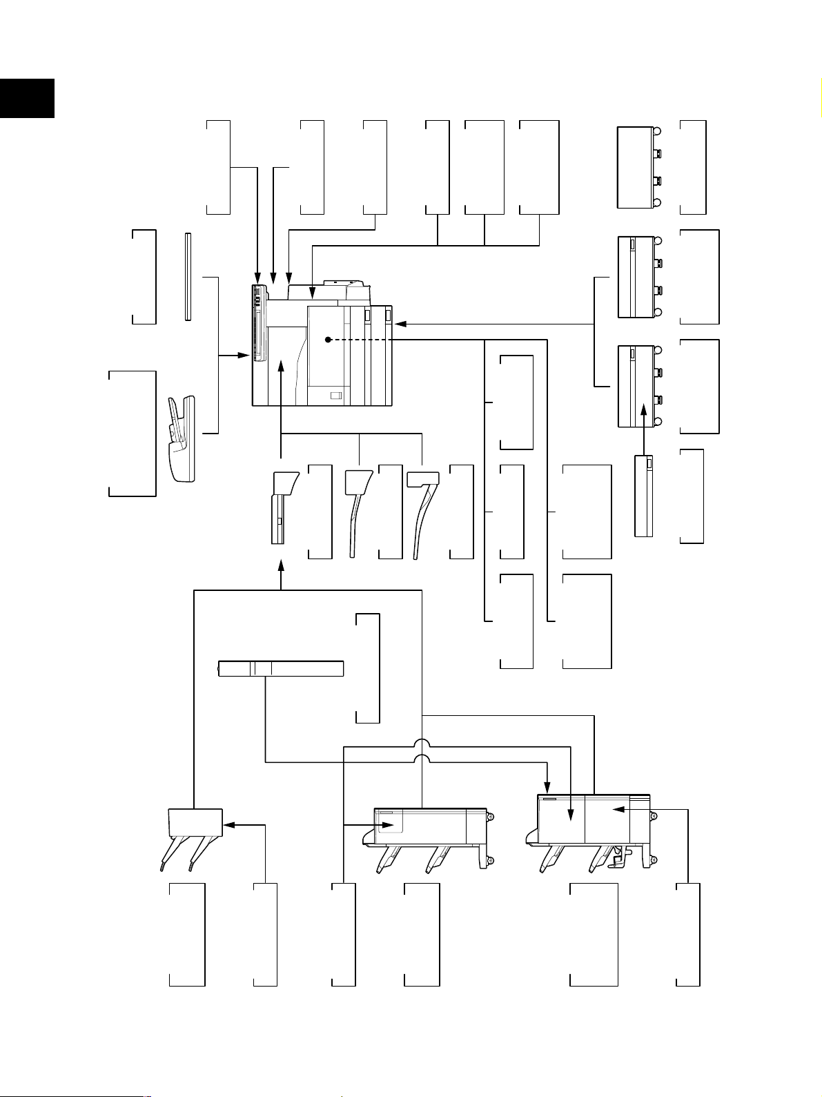
1.5 System List
KA-3511
Platen Cover
)
RADF
(
MR-3015
Document Feeder
Reversing Automatic
KK-3511
Work Tray
Key Counter
MU-8, MU-10
KN-3520
Bridge Kit
Damp Heater
MF-3520 U/E
MJ-5004
Job Separator
GM-1010
Printer Kit
MJ-5005
Offset Tray
Printer/
GM-2010
Scanner Kit
Scanner
GM-3010
Upgrade Kit
Adapter
GN-1010
Wireless LAN
PCI Slot
GO-1030
GD-1160
FAX Board
2nd Line for
NA/EU/TW/C
Desk
MH-1700
Feeder (LCF)
Large Capacity
KD-1012 A4/LT
KD-1011
Paper Feed
Pedestal (PFP)
MY-1021
Drawer Module
Board
GP-1030
Scrambler
Hole Punch Unit
MJ-6004 N/E/F/S
)
Finisher
MJ-1022
Hanging type
(
e-STUDIO350/450 SPECIFICATIONS 1 - 8 November 2003 © TOSHIBA TEC
STAPLE-1600
Staple Cartridge
STAPLE-2000
Staple Cartridge
)
Finisher
Console type
(
Fig. 1-501
MJ-1023
GD-1150
TW/C/AS
FAX Board
NA/AU/EU/
Finisher
stitcher type)
Console saddle
(
MJ-1024
STAPLE-600
Staple Cartridge
Page 17
2. OUTLINE OF THE MACHINE
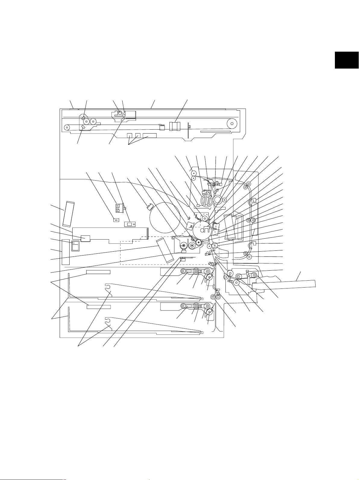
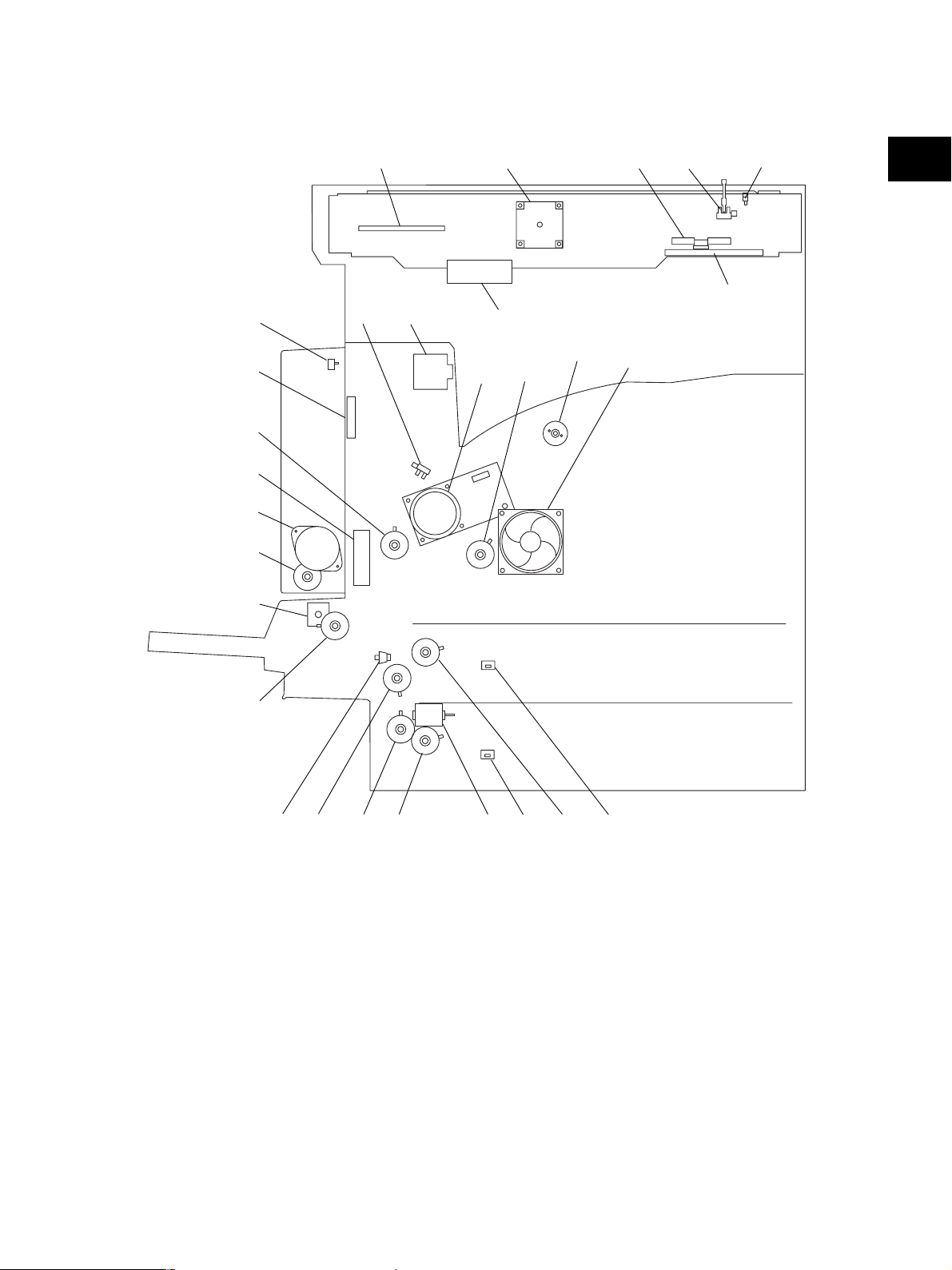
2.1 Sectional View
4
5
70 71
12
11
72
69
68
65
53
22
3
39
678
10
2
12
9
46 47
48
43
56,59 57 58
60
44
54
20,21
13
19
14
61 6263 64
15
27 28
45
51
52
41
31
67
66
40
29
42
55
23
23
32
24
30
25
36
37
3334
26
35
13
17
18
November 2003 © TOSHIBA TEC 2 - 1 e-STUDIO350/450 OUTLINE OF THE MACHINE
4950
20,21
Fig. 2-101
19
14
15
16
38
Page 18

Original glass
1
ADF original glass
2
Mirror-1
2
3
Mirror-2
4
Mirror-3
5
Reflector
6
Lens
7
Exposure lamp
8
Automatic original detection sensor
9
Toner cartridge switch
10
Laser unit
11
Laser unit cooling fan
12
Drawer pickup roller
13
Drawer feed roller
14
Drawer separation roller
15
Drawer transport roller
16
Drawer
17
Drawer tray
18
Drawer tray-up sensor
19
Drawer empty sensor
20
Drawer paper stock sensor
21
Drawer damp heater (JPD only)
22
Registration roller
23
Registration sensor
24
Upper drawer feed sensor
25
Lower drawer feed sensor
26
Exit sensor
27
ADU upper transport roller
28
ADU middle transport roller
29
ADU lower transport roller
30
ADU entrance sensor
31
ADU exit sensor
32
Bypass pickup roller
33
Bypass feed roller
34
Bypass separation roller
35
Bypass tray
36
37
Bypass paper sensor
38
Bypass feed sensor
39
Temperature/humidity sensor
40
Transfer charger
41
Separation charger
42
Drum
43
Developer unit
44
Cleaning blade
45
Recovery blade
46
Main charger
47
Discharge LED
48
Drum thermistor
49
Drum damp heater thermostat
50
Drum damp heater
51
Separation finger for drum
52
Toner bag full detection sensor-2
53
Auto-toner sensor
54
Toner recovery auger
55
Developer sleeve (magnetic roller)
56
Heat roller
57
Pressure roller
58
Cleaning roller
59
IH coil
60
Main thermistor / Edge thermistor
61
Separation finger for heat roller
62
Separation finger for pressure roller
63
Exit roller
64
Fuser thermostat
65
Middle fan
66
Exhaust fan
67
Sub-separation fan
68
Power supply cooling fan
69
Main switch
70
Front cover opening/closing switch
71
Cover opening/closing interlock switch
72
Polygonal motor
e-STUDIO350/450 OUTLINE OF THE MACHINE 2 - 2 November 2003 © TOSHIBA TEC
Page 19
14
13
5
2
6
1
3
2
4
12
7
15
16
28
17
18
19
20
11 10
9
8
23
22
24 26
21
November 2003 © TOSHIBA TEC 2 - 3 e-STUDIO350/450 OUTLINE OF THE MACHINE
25
Fig. 2-102
27 26
Page 20

Platen sensor
1
Scan motor
2
Carriage home position sensor
2
3
Scanner damp heater (Left)
4
Scanner damp heater (Right)
5
Scanner damp heater thermostat
6
IH board cooling fan
7
Developer unit cooling fan-1
8
Toner motor
9
Developer drive clutch
10
Main motor
11
Exit motor
12
Toner bag full detection sensor-1
13
ADU opening/closing switch
14
15
Fuser unit cooling fan
16
Registration clutch
17
ADU motor
18
ADU clutch
19
Bypass pickup solenoid
20
Bypass feed clutch
21
Side cover opening/closing switch
22
Transport clutch (High speed)
23
Transport clutch (Low speed)
24
Lower drawer feed clutch
25
Tray-up motor
26
Drawer detection switch
27
Upper drawer feed clutch
28
Developer unit cooling fan-2
e-STUDIO350/450 OUTLINE OF THE MACHINE 2 - 4 November 2003 © TOSHIBA TEC
Page 21
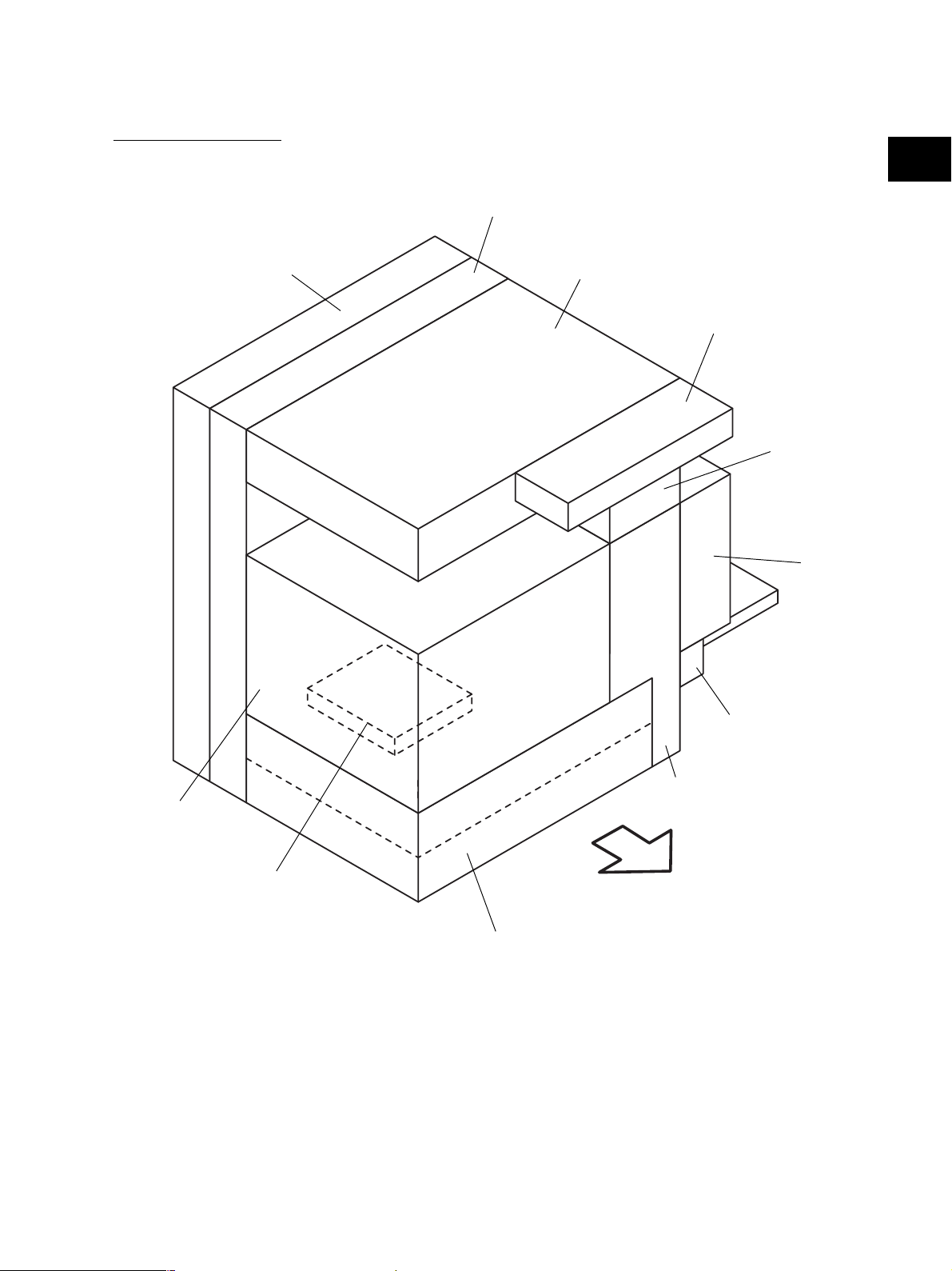
2.2 Electric Parts Layout
[A] Unit construction
2
Drive unit
PC board unit
Scanner unit
Control panel unit
Fuser unit
Automatic
duplexing unit
Bypass unit
Transport unit
Process unit
Laser unit
Paper feeder unit
Fig. 2-201
November 2003 © TOSHIBA TEC 2 - 5 e-STUDIO350/450 OUTLINE OF THE MACHINE
Front side
Page 22
[B] Scanner unit
(B-1) Motor, sensor, lamp
2
A4 series
S5
LT series
S6
S7
EXP
M1
M1
S3
Fig. 2-202-1
S2
S4
S1
Front side
S5
S4
S7
S6
EXP
S3
Fig. 2-202-2
e-STUDIO350/450 OUTLINE OF THE MACHINE 2 - 6 November 2003 © TOSHIBA TEC
S2
Front side
Page 23
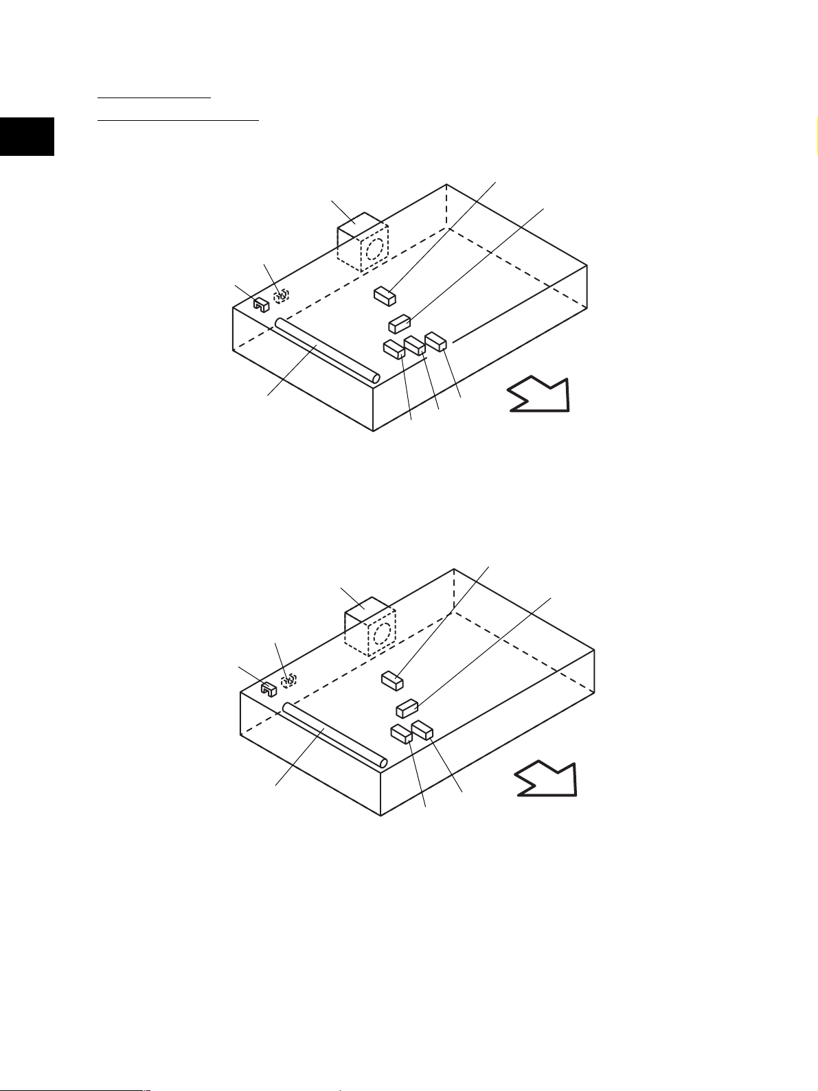
(B-2) PC board, heater, thermostat, other part
THMO2*
DH1*
INV
* ASD/AUD/CND/SAD/TWD models : Standard
NAD/MJD models : Option
DH2*
2
CCD
SLG
Front side
Fig. 2-203
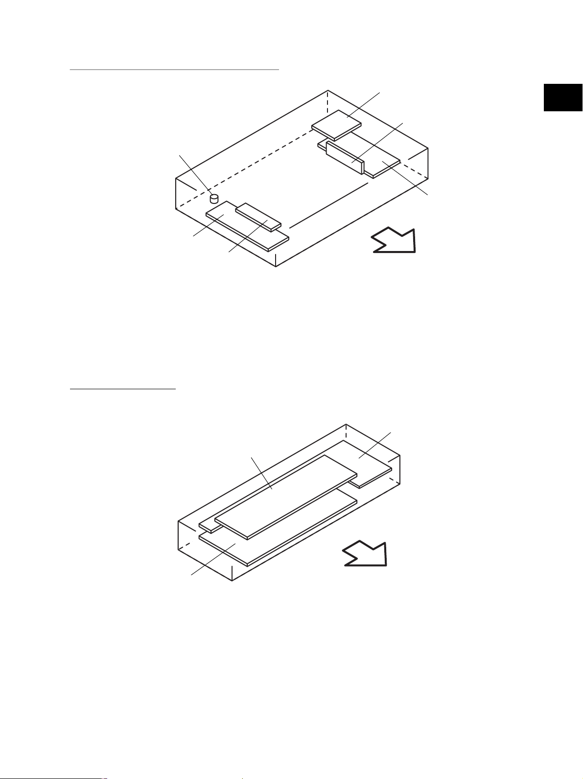
[C] Control panel unit
DSP
KEY
LCD
Front side
Fig. 2-204
November 2003 © TOSHIBA TEC 2 - 7 e-STUDIO350/450 OUTLINE OF THE MACHINE
Page 24
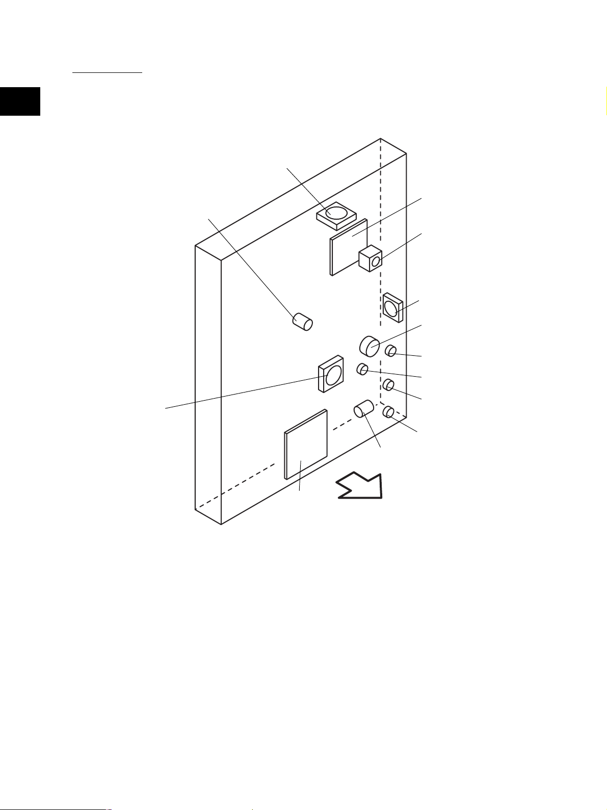
[D] Process unit
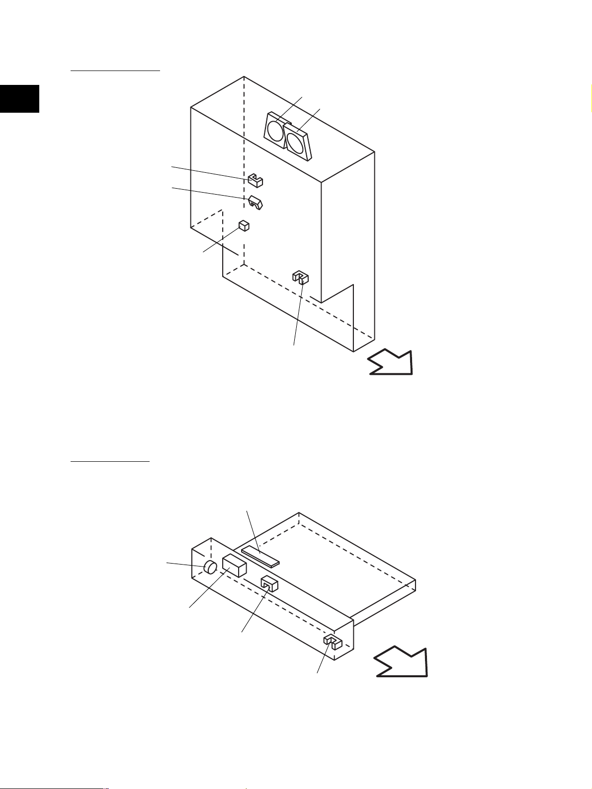
(D-1) Motor, sensor, switch, PC board
2
S8
M8
LRL
S9
S32
S31
S30
Fig. 2-205
S12
S10
M9
Front side
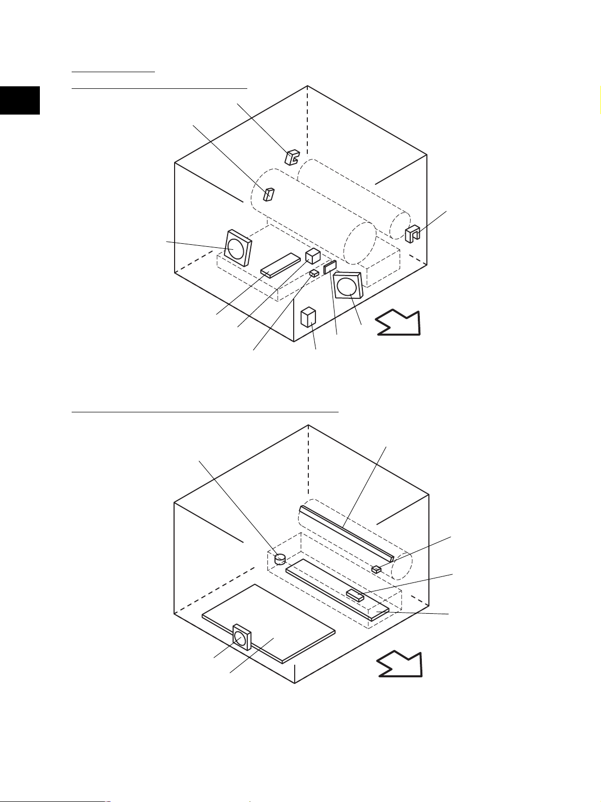
(D-2) Motor, sensor, lamp, heater, thermistor, thermostat
THMO3*
M16
PS
* ASD/AUD/CND/SAD/TWD models : Standard
NAD/MJD models : Option
ERS
THM3
S11
DH3*
Front side
Fig. 2-206
e-STUDIO350/450 OUTLINE OF THE MACHINE 2 - 8 November 2003 © TOSHIBA TEC
Page 25
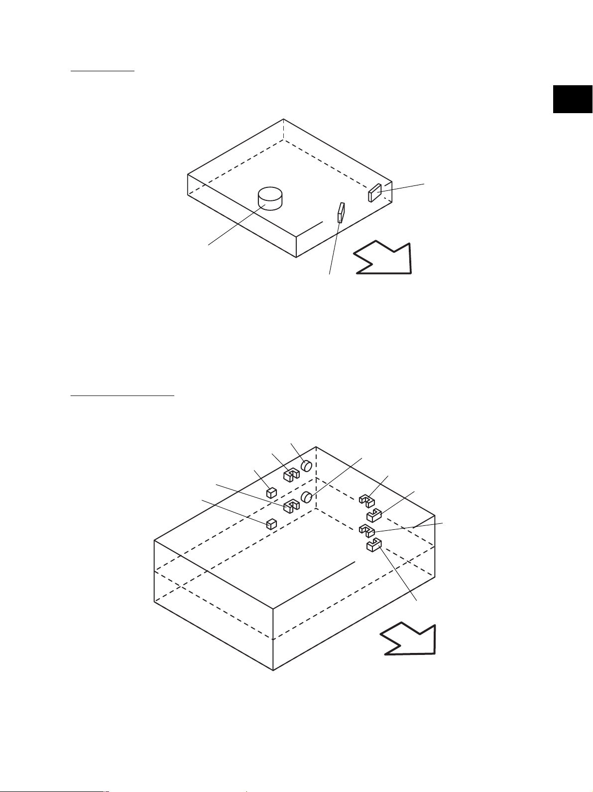
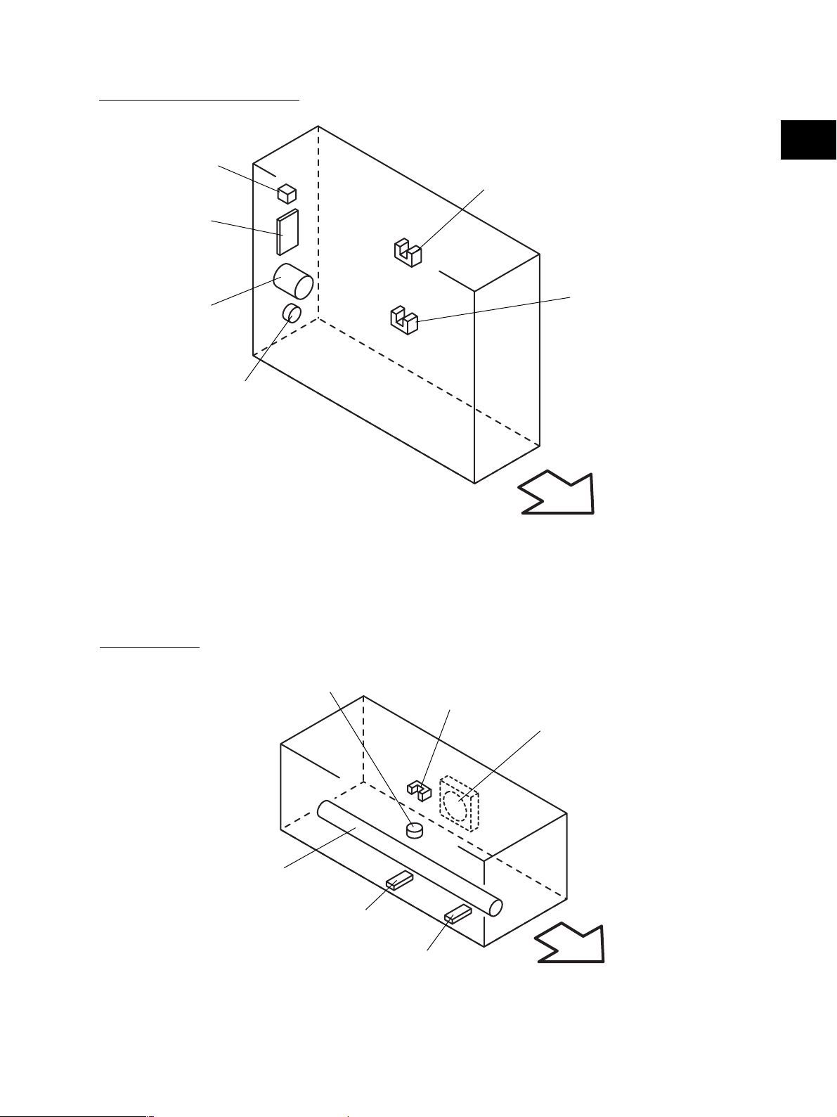
[E] Laser unit
2
SNS
M2
[F] Paper feeder unit
S23
S21
S22
S20
Fig. 2-207
CLT1
LDR
Front side
CLT2
S16
S18
S17
S19
Front side
Fig. 2-208
November 2003 © TOSHIBA TEC 2 - 9 e-STUDIO350/450 OUTLINE OF THE MACHINE
Page 26
[G] Transport unit
2
S13
S14
S33
M10
M11
S15
[H] Bypass unit
Front side
Fig. 2-209
SFB
CLT3
SOL1
S24
S25
Fig. 2-210
e-STUDIO350/450 OUTLINE OF THE MACHINE 2 - 10 November 2003 © TOSHIBA TEC
Front side
Page 27
[I] Automatic duplexing unit
S26
ADU
2
S27
M3
[J] Fuser unit
S28
CLT4
Front side
Fig. 2-211
THMO1
S29
M12
IH-COIL
THM1
THM2
Front side
Fig. 2-212
November 2003 © TOSHIBA TEC 2 - 11 e-STUDIO350/450 OUTLINE OF THE MACHINE
Page 28
[K] Drive unit
2
M13
IH
M7
M4
M15
M5
CLT5
M14
CLT6
CLT7
CLT8
M6
HVT
Front side
Fig. 2-213
e-STUDIO350/450 OUTLINE OF THE MACHINE 2 - 12 November 2003 © TOSHIBA TEC
Page 29
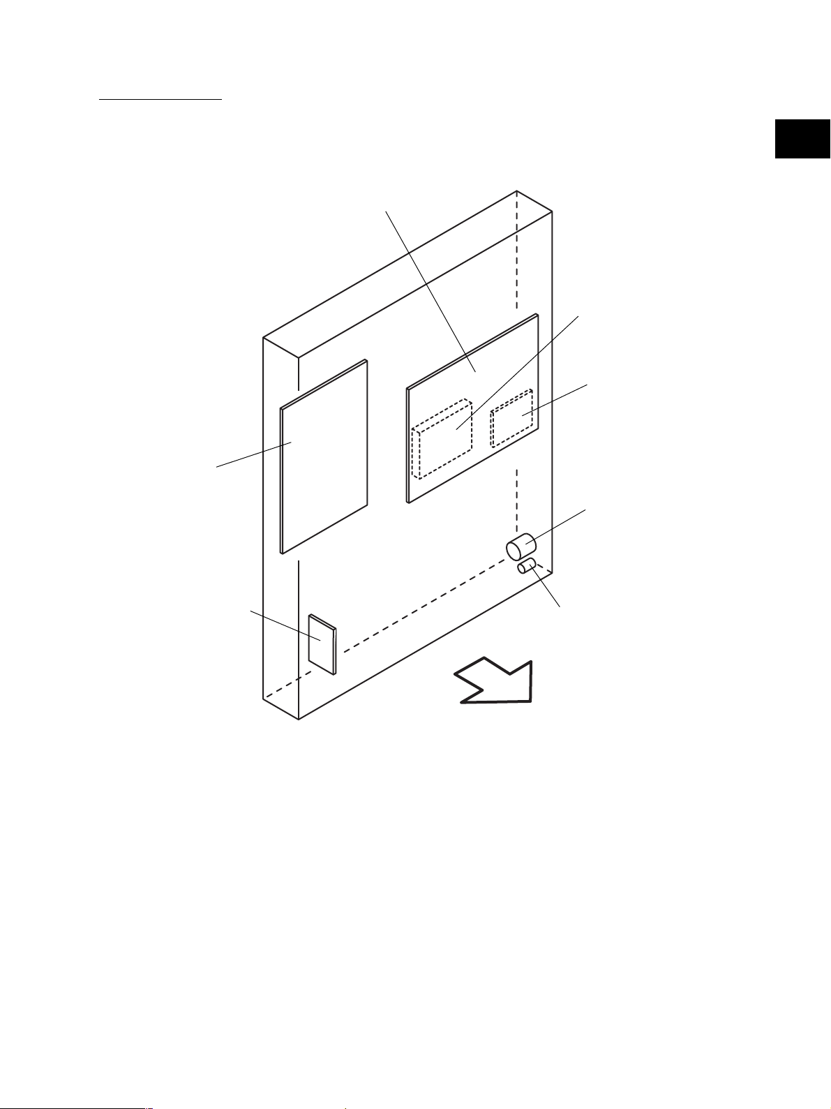
[L] PC board unit
LGC
2
SYS
HDD
NIC
FIL or FUS*
* NAD/SAD/TWD models : FIL (Standard)
ASD/AUD/CND models : FUS (Standard)
MJD model : FUS (Option)
NF
BRK
Front side
Fig. 2-214
November 2003 © TOSHIBA TEC 2 - 13 e-STUDIO350/450 OUTLINE OF THE MACHINE
Page 30

2.3 Symbols and Functions of Various Components
The column "P-I" shows the page and item number in the parts list.
2
(1) Motors
Symbol
M1
M2
M3
M4
M5
M6
M7
M8
M9
M10
M11
M12
M13
M14
M15
M16
Name
SCAN-MOT
Scan motor
M/DC-POL
Polygonal motor
ADU-MOT
ADU motor
EXIT-MOT
Exit motor
MAIN-MOT
Main motor
TRY-MOT
Tray-up motor
TNR-MOT
Toner motor
LSU-FAN-MOT
Laser unit cooling fan
MID-FAN-MOT
Middle fan
EXIT-FAN-MOT
Exhaust fan
SP-FAN-MOT
Sub-separation fan
FUS-FAN-MOT
Fuser unit cooling fan
IH-FAN-MOT
IH board cooling fan
DEV-FAN-MOT1
Developer unit cooling fan-1
DEV-FAN-MOT2
Developer unit cooling fan-2
PS-FAN-MOT
Power supply cooling fan
Function
Driving the carriages
Driving the polygonal mirror
Driving the automatic duplexing unit
Driving the exit roller
Driving the drum, developer unit, fuser
unit, registration roller, transport
rollers, feed rollers and pickup rollers
Driving the lifting movement of trays in
upper/lower drawer
Supplying the toner
Cooling down the laser unit
Cooling down the inside of the
equipment
Exhausting ozone
Assisting the paper separation process
(Absorbing the paper from the drum)
Cooling down the fuser unit
Cooling down the IH board
Cooling down the developer unit
Cooling down the developer unit
Cooling down the power supply unit
Remarks
B-1
E
I
K
K
K
K
D-1
D-1
G
G
J
K
K
K
D-2
P- I
P13 - I8
P9 - I5
P32 - I18
P6 - I20
P12 - I26
P4 - I26
P28 - I9
P9 - I3
P9 - I3
P11 - I2
P11 - I2
P30 - I13
P7 - I12
P6 - I18
P6 - I39
P9 - I7
e-STUDIO350/450 OUTLINE OF THE MACHINE 2 - 14 November 2003 © TOSHIBA TEC
Page 31

(2) Sensors and switches
Symbol
S1-5
S6
S7
S8
S9
S10
S11
S12
S13
S14
S15
S16
S17
S18
S19
S20
S21
Name
APS1-3, APS-C, APS-R
Automatic original detection sensor
HOME-SNR
Carriage home position sensor
PLTN-SNR
Platen sensor
TNR-SW
Toner cartridge switch
USD-TNR-FLL-SNR1
Toner bag full detection sensor-1
USD-TNR-FLL-SNR2
Toner bag full detection sensor-2
ATTNR-SNR
Auto-toner sensor
TEMP/HUMI-SNR
Temperature/humidity sensor
RGST-SNR
Registration sensor
FED-U-SNR
Upper drawer feed sensor
FED-L-SNR
Lower drawer feed sensor
CST-U-TRY-SNR
Upper drawer tray-up sensor
CST-L-TRY-SNR
Lower drawer tray-up sensor
EMP-U-SNR
Upper drawer empty sensor
EMP-L-SNR
Lower drawer empty sensor
NEMP-U-SNR
Upper drawer paper stock sensor
NEMP-L-SNR
Lower drawer paper stock sensor
Function
Original size detection
Carriage home position detection
Opening/closing detection of platen
cover or RADF
Toner cartridge presence/absence
detection
Detecting if the used toner is full in the
toner bag
Detecting the presence/absence of
the toner bag
Used toner amount defection in the
toner bag
Detecting the density of toner in the
developer unit
Detecting the temperature and
humidity inside of the equipment
Detecting the paper transport at the
registration roller section
Detecting paper jam and paper
transport at upper drawer feeding
section
Detecting paper jam and paper
transport at lower drawer feeding
section
Position detection of the lifting tray of
the upper drawer
Position detection of the lifting tray of
the lower drawer
Paper presence/absence detection in
the upper drawer
Paper presence/absence detection in
the lower drawer
Paper amount detection in the upper
drawer
Paper amount detection in the lower
drawer
Remarks
B-1
B-1
B-1
D-1
D-1
D-1
D-2
D-1
G
G
G
F
F
F
F
F
F
P-I
S1-4:P10 - I12
S-5:P10 - I13
P10 - I17
P13 - I10
P28 - I23
P12 - I28
P25 - I59
P26 - I19
P5 - I15
P19 - I11
P19 - I11
P19 - I5
P14 - I30
P14 - I30
P14 - I30
P14 - I30
P14 - I30
P14 - I30
2
November 2003 © TOSHIBA TEC 2 - 15 e-STUDIO350/450 OUTLINE OF THE MACHINE
Page 32

Symbol
S22
2
S23
S24
S25
S26
S27
S28
S29
S30
S31
S32
S33
CST-U-SW
Upper drawer detection switch
CST-L-SW
Lower drawer detection switch
SFB-SNR
Bypass paper sensor
SFB-FED-SNR
Bypass feed sensor
ADU-SET-SW
ADU opening/closing switch
ADU-TRU-SNR
ADU entrance sensor
ADU-TRL-SNR
ADU exit sensor
EXIT-SNR
Exit sensor
MAIN-SW
Main switch
FRNT-COV-SW
Front cover opening/closing switch
COV-INTLCK-SW
Cover opening/closing interlock switch
SIDE-COV-SW
Side cover opening/closing switch
Name
Function
Detecting presence/absence of the
upper drawer
Detecting presence/absence of the
lower drawer
Detecting presence/absence of paper
on the bypass tray
Detecting the transporting paper fed
from the bypass tray
Automatic duplexing unit opening/
closing detection
Detecting the transporting paper at
automatic duplexing unit entrance
section
Detecting the transporting paper in
automatic duplexing unit
Detecting the transporting paper at
the exit section
Turning ON/OFF of the equipment
Detecting opening/closing of the front
cover
Controlling cutoff and supply of the
24V voltage by opening/closing of the
front cover or jam access cover
Side cover opening/closing detection
Remarks
F
F
H
H
I
I
I
J
D-1
D-1
D-1
G
P-I
P4 - I101
P4 - I101
P18 - I5
P18 - I5
P32 - I43
P32 - I31
P32 - I31
P31 - I21
P5 - I10
P5 - I7
P5 - I19
P19 - I2
e-STUDIO350/450 OUTLINE OF THE MACHINE 2 - 16 November 2003 © TOSHIBA TEC
Page 33

(3) Electromagnetic clutches
Symbol
CLT1
CLT2
CLT3
CLT4
CLT5
CLT6
CLT7
CLT8
Name
CST-U-FEED-CLT
Upper drawer feed clutch
CST-L-FEED-CLT
Lower drawer feed clutch
SFB-FEED-CLT
Bypass feed clutch
ADU-CLT
ADU clutch
RGST-CLT
Registration clutch
DEV-CLK
Developer drive clutch
CST-TR-L-CLT
Transport clutch (Low speed)
CST-TR-H-CLT
Transport clutch (High speed)
Function
Driving the upper drawer pickup roller
Driving the lower drawer pickup roller
Driving the bypass pickup roller and
bypass feed roller
Driving the automatic duplexing unit
Driving the registration roller
Driving the magnetic roller of the
developer unit
Driving the transport roller
(Low speed)
Driving the transport roller
(High speed)
Remarks
F
F
H
I
K
K
K
K
P-I
P14 - I29
P14 - I29
P17 - I20
P32 - I16
P19 - I31
P12 - I36
P15 - I20
P15 - I16
2
(4) Solenoids
Symbol
SOL1
SFB-SOL
Bypass pickup solenoid
Name
Function
Driving the bypass pickup roller
Remarks
H
P-I
P18 - I11
November 2003 © TOSHIBA TEC 2 - 17 e-STUDIO350/450 OUTLINE OF THE MACHINE
Page 34

(5) PC boards
Symbol
2
CCD
SLG
DSP
KEY
LRL
LDR
SNS
SFB
ADU
IH
SYS
LGC
NIC
FIL
FUS
PWA-F-CCD
CCD driving PC board (CCD board)
PWA-F-SLG
Scanning section control PC board
(SLG board)
PWA-F-DSP
Display PC board (DSP board)
PWA-F-KEY
Key control PC board (KEY board)
PWA-F-LRL
Laser control signal relay PC board
(LRL board)
PWA-F-LDR
Laser driving PC board (LDR board)
PWA-F-SNS
H-sync signal detection PC board
(SNS board)
PWA-F-SFB
Bypass tray slide guide width detection
PC board (SFB board)
PWA-F-ADU
ADU driving PC board (ADU board)
PS-IH
IH control PC board (IH board)
PWA-F-SYS
System control PC board (SYS board)
PWA-F-LGC
Logic PC board (LGC board)
PWA-F-NIC
NIC board
PWA-F-FIL
Filter PC board (FIL board)
PWA-F-FUS
Fuse PC board (FUS board)
Name
Function
Controlling CCD and outputting the
analog signal
Controlling the original scanning
section and RADF
Controlling LCD and the touch panel
on the control panel
Detecting the button entry and
controlling LED on the control panel
Relaying the control signals of the
laser unit
Driving the laser diode
Detection of the laser beam position
Detection of the bypass tray slide
guide width
Controlling the automatic duplexing
unit
Controlling each IH coil in the fuser
unit
Controlling the whole system and
image processing
Controlling the print engine section
Network connection interface
Cutting noise of the AC power
Power supplying to each damp heater
*NAD/SAD/TWD models: Standard
Supplying the power to each damp
heater
*ASD/AUD/CND models: Standard
*MJD model: Option
Remarks
B-2
B-2
C
C
D-1
E
E
H
I
K
L
L
L
L
L
P-I
P10 - I10
P10 - I38
P3 - I26
P3 - I25
P9 - I23
P9 - I5
P9 - I5
P16 - I13
P32 - I30
P7 - I2
P7 - I34
P8 - I7
P7 - I22
P6 - I24
P6 - I24
e-STUDIO350/450 OUTLINE OF THE MACHINE 2 - 18 November 2003 © TOSHIBA TEC
Page 35

(6) Lamps and heaters
Symbol
EXP
ERS
IH-COIL
DH1
DH2
DH3
Name
LP-EXPO
Exposure lamp
LP-ERS
Discharge LED
IH-COIL
IH coil
SCN-L-DH
Scanner damp heater (Left)
SCN-R-DH
Scanner damp heater (Right)
DRM-DH
Drum damp heater
Function
Exposing the original to the light
Removing the residual charge from
the drum surface
Heating the fuser roller
Preventing condensation of the
mirrors of the carriages
*ASD/AUD/CND/SAD/TWD models:
Standard
*NAD/MJD models: Option
Preventing condensation of the lens
*ASD/AUD/CND/SAD/TWD models:
Standard
*NAD/MJD models: Option
Preventing condensation of the drum
*ASD/AUD/CND/SAD/TWD models:
Standard
*NAD/MJD models: Option
Remarks
B-1
D-2
J
B-2
B-2
D-2
P-I
P21 - I6
P25 - I33
P31 - I23
P10 - I22
P10 - I32
P27 - I7
2
(7) Thermistors and thermostats
Symbol
THM1
THM2
THM3
THMO1
THMO2
THMO3
THMS-C-HTR
Main thermistor
THMS-S-HTR
Edge thermistor
THMS-DRM
Drum thermistor
THERMO-FSR
Fuser thermostat
THERMO-SCN-DH
Scanner damp heater thermostat
THERMO-DRM-DH
Drum damp heater thermostat
Name
Function
Detecting the surface temperature at
the center part of the fuser roller
Detecting the surface temperature at
the edge of the fuser roller
Detecting the temperature at the drum
surface
Preventing overheating in the fuser
unit
Controlling the temperature of the
scanner damp heater
Controlling the temperature of the
drum damp heater
Remarks
J
J
D-2
J
B-2
D-2
P-I
P29 - I10
P29 - I10
P26 - I29
P29 - I9
P10 - I22
P27 - I7
November 2003 © TOSHIBA TEC 2 - 19 e-STUDIO350/450 OUTLINE OF THE MACHINE
Page 36

(8) Transformer
Symbol
2
HVT
PS-HVT
High-voltage transformer
Name
Function
Generating high-voltage and supply-
ing it to the following sections
• Main charger wire
• Main charger grid
• Developer bias
• Transfer bias
• Separation bias
Remarks
K
P-I
P4 - I29
(9) Others
Symbol
INV
LCD
PS
HDD
NF
BRK
INV-EXP
Inverter board
LCD
LCD panel
PS-ACC
Switching power supply
HDD
Hard disk
NS-FIL
Noise filter
BREAKER
Breaker
Name
Function
Controlling the exposure lamp
Displaying and entering each informa-
tion
Generating DC voltage and supplying
it to each section of the equipment
Storing the program data and image
data
Cutting noise of AC power
Preventing the inflow of overcurrent to
the equipment
Remarks
B-2
C
D-2
L
L
L
P-I
P21 - I7
P3 - I19
P9 - I7
P7 - I25
P6 - I13
P6 - I14
e-STUDIO350/450 OUTLINE OF THE MACHINE 2 - 20 November 2003 © TOSHIBA TEC
Page 37

2.4 General Description
2.4.1 System block diagram
Laser diode
SNS
LRL Laser unit
LGCSYSSLGCCD
LDR
Laser beam sensor
ASIC
ASIC
RS-232C
2
Finisher
Finisher
Download jig
8
Bus transceiver
Data-bus
512KB
16
8
)
32MB
SDRAM
Page memory
32
ASIC
(
NVRAM
8
256KB
Flash ROM
24MHz
Engine-CPU
Data-bus
16
32
PCI-bus
Bridge unit
IPC
8
SRAM
128KB
888
8KB
NVRAM
ASIC
266MHz
3232
System-CPU
Job separator/Offset tray
Clutches
Sensors Solenoids
Switches
I/O
HVT
ADU Motors
Bypass
unit
Key copy
counter
Copy key
PFP/LCF
64
64
Data-bus
Bus transceiver
SRAM
512KB
Battery
RTC
ASIC
card
)
DIMM
128MB
(
Main memory
Flash ROM
32 32
Flash ROM
32 16
16
4MB x 2
2MB x 2
Option
:
Download jig
)
NIC
IEEE-1284
Parallel port
(
LAN connector
Printer kit,
Printer/Scanner kit,
Scanner upgrade kit
ASIC
FAX
FAX
)
)
NCU
NCU
LINE-1
(
PSTN
10BASE-T/100BASE-TX
(
PSTN
External TEL
)
LINE-2
(
Modem
)
Odd
(
A/D
Amp
ASIC
CCD
32
Motors
8
22MHz
16168
Scanner-CPU
A/D
Data-bus
Amp
)
Even
(
512KB
Flash ROM
SRAM
128KB
8
RADF
Download jig
Control panel
32
Scrambler board
PCI external slot
Scrambler board
ASIC
)
)
host-1
device
(
(
USB connector
USB connector
HDD
Dongle
)
host-2
(
USB connector
Dongle
Fig. 2-401
November 2003 © TOSHIBA TEC 2 - 21 e-STUDIO350/450 OUTLINE OF THE MACHINE
Page 38

2.4.2 Construction of boards
(a) Construction diagram of boards
2
This system consists of the following including the SYS board as a main board.
AC input
Control panel
KEY
Scanner unit
CCD
INV
Main switch
FIL
or
FUS
DSP
NIC
SLG
PS-ACC
Cover opening/closing
interlock switch
SYS
IH
:
DC power supply line
:
AC power supply line
:
Signal line
Fig. 2-402
LRL
LGC
Laser unit
ADU
SFB
HVT
(b) Function of each board
CCD board:
This is the board to convert the reflected light by the original to electrical signals. It consists of the
CCD, and its peripheral circuitry. The CCD converts the reflected light by the original to analog signal
and outputs it to the SLG board.
LDR
SNS
SLG board:
This is the board to mainly control the scanning function (scanner unit) and consists of the Scanner-
CPU, ASIC, memory (Flash ROM and SRAM), A/D converter, driver for motor drive, etc. When
scanning the original, the exposure lamp and scan motor are driven by the command from the
Scanner-CPU. The analog signal output from the CCD board is then converted to digital signal by
the A/D converter. Image processing is performed by ASIC.
INV board:
This is the board on which the lighting control circuit of the exposure lamp is mounted. The exposure
lamp lights by the command from the Scanner-CPU.
DSP board:
This is the board to mainly control the control panel. The panel processing CPU detecting the input
from each button and touch panel, and the lighting control circuit for the backlight of the LCD are
mounted. And it relays the control signal of the control panel from the SYS board to the LCD and KEY
board.
e-STUDIO350/450 OUTLINE OF THE MACHINE 2 - 22 November 2003 © TOSHIBA TEC
Page 39

KEY board:
This is the board on which each button switch and each LED on the control panel are mounted.
LDR board:
This is the board on which the laser diode and the ASIC are mounted. The laser is emitted based on
the output image data signal from the ASIC on the LGC board.
SNS board:
This is the board on which the light sensor for detecting the radiating position of the laser is mounted.
It outputs the H-sync signal to ASIC on the LGC board.
LRL board:
This is the board to relay each signal transmitted between the LGC board and laser unit (LDR and
SNS boards).
SFB board:
This is the board on which the circuit pattern is printed. It detects the position of the slide guide of the
bypass unit.
ADU board:
This is the board to relay each signal between the ASIC on the LGC board and the electric parts
(motor, sensor, clutch) in the ADU.
2
IH board:
This is the board to generate the electric power for driving the IH coil of the fuser unit from the AC
electric power input via the switching power supply. And then it is provided.
SYS board:
This is the main board taking a leading part in all systems. It consists of the System-CPU, ASIC,
memory (DIMM, SDRAM, Flash ROM, SRAM, NVRAM), RTC (Real Time Clock IC), etc. The Sys-
tem-CPU controls each ASIC to perform the control of the image processing, image memory (page
memory, main memory, HDD), external interface (RS-232C, IEEE-1284, USB, PCI), NIC and FAX.
Based on the input data from the control panel, the System-CPU communicates with the Scanner-
CPU on the SLG board and Engine-CPU on the LGC board, and then issues an operation command
to the scanner and printer engine section.
LGC board:
This is the board to mainly control the printing function (printer engine). It consists of the Engine-
CPU, ASIC, memory (Flash ROM, SRAM, NVRAM), driver for motor drive, etc. The Engine-CPU
controls each ASIC to drive I/O (for the electrical parts) of each section in the system. It leads to the
operation of the laser unit, developer unit, drum, drawers, bypass unit, ADU, etc. Thus printing is
performed.
November 2003 © TOSHIBA TEC 2 - 23 e-STUDIO350/450 OUTLINE OF THE MACHINE
Page 40

NIC board:
This is the interface board to connect this equipment to the LAN environment (10BASE-T, 100BASE-
2
TX) to communicate with PCs, etc.
FIL board:
This is the board to cut off the noise of AC power from outside, and supply the driving AC power to
the damp heater for condensation prevention of each section (scanner and drum).
FUS board:
This is the board to provide the AC electric power for driving to the damp heater for preventing of the
condensation of each section (scanner and drum).
HVT:
This is the board to generate the DC high voltage from +24V to provide the bias to the section of the
main charger, developer, transfer, and separation.
PS-ACC:
This is the unit to generate each DC voltage, which is used in the equipment, from external AC
electric power input. And then it is provided to each electrical part.
e-STUDIO350/450 OUTLINE OF THE MACHINE 2 - 24 November 2003 © TOSHIBA TEC
Page 41

2.5 Installation and Replacement of Covers and PC boards
2.5.1 External covers
[A] Front cover
(1) Open the front cover.
(2) Remove the toner bag.
2
Fig. 2-501
Fig. 2-502
(3) Pull up the hinge pin and extract it.
(4) Take off the front cover.
[B] Front left cover
(1) Open the front cover.
(2) Remove 1 screw and front left cover.
Fig. 2-503
Guide
Fig. 2-504
November 2003 © TOSHIBA TEC 2 - 25 e-STUDIO350/450 OUTLINE OF THE MACHINE
Page 42

[C] Rear cover
(1) Remove 7 screws and take off the rear cover.
2
2
Fig. 2-505
[D] Left upper cover
(1) Remove 2 screws and take off the left upper
cover.
[E] Front upper cover
(1) Take off the left upper cover
( Chapter 2.5.1 [D]).
(2) Remove 2 screws and take off the front upper
cover.
[F] Right upper cover
(1) Remove 3 screws and take off the right upper
cover.
Fig. 2-506
Fig. 2-507
Fig. 2-508
e-STUDIO350/450 OUTLINE OF THE MACHINE 2 - 26 November 2003 © TOSHIBA TEC
Page 43

[G] Upper rear cover
(1) Take off the RADF or platen cover.
(2) Take off the left upper cover
( Chapter 2.5.1 [D]).
(3) Take off the right upper cover
( Chapter 2.5.1 [F]).
(4) Remove 2 screws and upper rear cover.
[H] Receiving tray
(1) Remove 2 screws and take off the receiving
tray.
2
Fig. 2-509
[I] Tray back cover
(1) Take off the receiving tray ( Chapter 2.5.1
[H]).
(2) Remove 1 screw and take off the receiving
tray back cover.
[J] Left cover
(1) Remove 3 screws and take off the left cover.
Fig. 2-510
Fig. 2-511
Fig. 2-512
November 2003 © TOSHIBA TEC 2 - 27 e-STUDIO350/450 OUTLINE OF THE MACHINE
Page 44

[K] Left rear cover
(1) Take off the left upper cover
2
2
( Chapter 2.5.1 [D]).
(2) Remove 3 screws and take off the left rear
cover.
Fig. 2-513
[L] IH terminal cover
(1) Open the ADU, jam access cover and fuser
unit cover.
(2) Remove 2 screws and take off the IH terminal
cover.
[M] Right front hinge cover
(1) Pull out the upper and lower drawers.
(2) Remove 2 screws and take off the right front
hinge cover.
[N] Right rear hinge cover
(1) Remove 2 screws and take off the right rear
hinge cover.
Fig. 2-514
Fig. 2-515
Fig. 2-516
e-STUDIO350/450 OUTLINE OF THE MACHINE 2 - 28 November 2003 © TOSHIBA TEC
Page 45

[O] Right lower cover
(1) Take off the right rear hinge cover
( Chapter 2.5.1 [N]).
(2) Remove 2 screws and take off the right lower
cover.
[P] Right rear cover
(1) Take off the right upper cover
( Chapter 2.5.1 [F]).
(2) Take off the IH terminal cover
( Chapter 2.5.1 [L]).
(3) Take off the right rear hinge cover
( Chapter 2.5.1 [N]).
(4) Remove 2 screws and take off the right rear
cover.
2
Fig. 2-517
[Q] Front right cover
(1) Take off the front cover
( Chapter 2.5.1 [A]).
(2) Take off the receiving tray
( Chapter 2.5.1 [H]).
(3) Take off the right upper cover
( Chapter 2.5.1 [F]).
(4) Take off the upper drawer. Open the bypass
tray and ADU.
(5) Remove 2 screws and take off the front right
cover.
Fig. 2-518
Fig. 2-519
November 2003 © TOSHIBA TEC 2 - 29 e-STUDIO350/450 OUTLINE OF THE MACHINE
Page 46

2.5.2 PC boards
[A] Logic PC board (LGC board)
2
2
(A-1) LGC board
(1) Take off the rear cover (
Chapter 2.5.1 [C]).
(2) Loosen 8 screws and take off the LGC board
cover.
Fig. 2-520
(3) Disconnect 15 connectors and 1 connector
with lock.
(4) Remove 4 screws and release 2 locking sup-
ports. Then take off the LGC board.
(A-2) LGC board unit
(1) Take off the rear cover ( Chapter 2.5.1 [C]).
(2) Loosen 8 screws and take off the LGC board
cover.
(3) Disconnect 15 connectors, 1 connector with
lock and 1 joint connector fixed to the case.
Lock connector
Fig. 2-521
Fig. 2-522
Lock connector
Fig. 2-523
e-STUDIO350/450 OUTLINE OF THE MACHINE 2 - 30 November 2003 © TOSHIBA TEC
Page 47

(4) Release all the harnesses from the harness
clamps and holders on the case.
(5) Remove 5 screws and take off the LGC board
with the whole case.
2
Fig. 2-524
[B] Hard disk
(1) Take off the rear cover ( Chapter 2.5.1 [C]).
(2) Loosen 9 screws and take off the SYS board
upper cover.
(3) Disconnect 2 connectors.
(4) Loosen 5 screws and take off the hard disk
with the whole SYS board lower cover.
Fig. 2-525
Fig. 2-526
Fig. 2-527
November 2003 © TOSHIBA TEC 2 - 31 e-STUDIO350/450 OUTLINE OF THE MACHINE
Page 48

(5) Remove 4 screws and take off the hard disk.
2
2
Fig. 2-528
[C] System control PC board (SYS board)
(1) Take off the rear cover ( Chapter 2.5.1 [C]).
(2) Take off the hard disk with the whole SYS
board lower cover ( Chapter 2.5.2 [B]).
(3) Disconnect 4 connectors.
(4) Release all the harnesses from harness
clamps and holders on the case.
(5) Remove 5 screws and take off the SYS board
with the whole case.
Fig. 2-529
Fig. 2-530
Fig. 2-531
e-STUDIO350/450 OUTLINE OF THE MACHINE 2 - 32 November 2003 © TOSHIBA TEC
Page 49

(6) Remove 12 screws, take off the NIC board
and SYS board.
[D] Switching power supply
(1) Take off the left cover ( Chapter 2.5.1 [J]).
(2) Remove 2 screws. Disconnect 2 connectors
with lock on the front side and 1 connector
while releasing the harness from the holder
on the right side of the bracket.
SYS board
2
NIC board
Fig. 2-532
(3) Disconnect 3 connectors while the switching
power supply is pulled out to the front and take
off the switching power supply.
[E] Power supply cooling fan
(1) Take off the left cover ( Chapter 2.5.1 [J]).
(2) Remove 2 screws and take off the power sup-
ply cooling fan on the switching power sup-
ply.
Note:
When installing, pay attention to the direction
of the wind from the fan.
Fig. 2-533
Fig. 2-534
Fig. 2-535
November 2003 © TOSHIBA TEC 2 - 33 e-STUDIO350/450 OUTLINE OF THE MACHINE
Page 50

[F] High-voltage transformer
(1) Take off the rear cover ( Chapter 2.5.1 [C]).
2
2
(2) Disconnect 7 connectors.
(3) Remove 2 screws and release 2 locking sup-
ports. Then take off the high-voltage trans-
former.
Note:
When installing, make sure to match the col-
ors of connectors and harnesses according
to the color instruction on the board.
Fig. 2-536
[G] Noise filter
(1) Take off the rear cover and right lower cover
( Chapter 2.5.1 [C][O]).
(2) Disconnect 4 connectors. Remove 1 screw and
1 washer. Then take off the noise filter.
White Black
Fig. 2-537
e-STUDIO350/450 OUTLINE OF THE MACHINE 2 - 34 November 2003 © TOSHIBA TEC
Page 51

2.6 Options
[A] MR-3015 (Reversing Automatic Document
Feeder (RADF))
(1) Turn OFF the power and unplug the power
cable.
(2) Take off the connector cover.
(3) Disconnect the connector.
2
Fig. 2-601
(4) Remove 2 screws on the rear side.
(5) Open the RADF.
Fig. 2-602
Fig. 2-603
Fig. 2-604
November 2003 © TOSHIBA TEC 2 - 35 e-STUDIO350/450 OUTLINE OF THE MACHINE
Page 52

(6) Remove 2 screws on the front side.
2
2
Fig. 2-605
(7) Slide the RADF backward and take off by lift-
ing it up.
[B] KD-1011 (Paper Feed Pedestal (PFP))
(1) Turn OFF the power and unplug the power
cable.
(2) Remove 7 screws and take off the rear cover
of the equipment.
Note:
Disconnect the connector of the RADF first
when the RADF is installed.
(3) Remove 1 screw and the ground wire, and then
disconnect 2 connectors (3 if the optional
damp heater is installed).
Fig. 2-606
Fig. 2-607
Connector of optional
damp heater
Fig. 2-608
e-STUDIO350/450 OUTLINE OF THE MACHINE 2 - 36 November 2003 © TOSHIBA TEC
Page 53

(4) Remove 2 screws and take off 2 fixing brack-
ets on the rear side.
(5) Take off the lower drawer of the equipment and
PFP upper drawer.
2
Fig. 2-609
(6) Remove 4 screws and take off 2 fixing brack-
ets on the front side.
(7) Lift up the equipment and take off the PFP.
Fig. 2-610
Fig. 2-611
Fig. 2-612
November 2003 © TOSHIBA TEC 2 - 37 e-STUDIO350/450 OUTLINE OF THE MACHINE
Page 54

[C] KD-1012 (Large Capacity Feeder (LCF))
(1) Turn OFF the power and unplug the power
2
2
cable.
(2) Remove 7 screws and take off the rear cover
of the equipment.
Note:
Disconnect the connectors of the RADF first
when the RADF is installed.
Fig. 2-613
(3) Remove 1 screw and the ground wire, and
then disconnect 2 connectors (3 if the optional
damp heater is installed).
Connector of optional
damp heater
(4) Remove 2 screws and take off 2 fixing brack-
ets on the rear side.
(5) Take off the lower drawer of the equipment.
Fig. 2-614
Fig. 2-615
Fig. 2-616
e-STUDIO350/450 OUTLINE OF THE MACHINE 2 - 38 November 2003 © TOSHIBA TEC
Page 55

(6) Pull out the LCF drawer.
(7) Remove 4 screws and take off 2 fixing brack-
ets on the front side.
2
Fig. 2-617
(8) Lift up the equipment and take off the LCF.
Fig. 2-618
Fig. 2-619
November 2003 © TOSHIBA TEC 2 - 39 e-STUDIO350/450 OUTLINE OF THE MACHINE
Page 56

[D] MJ-1022 (Hanging finisher)
(D-1) When PFP/LCF is not installed
2
2
(1) Turn OFF the power and unplug the power
cable.
(2) Take off the connector cover and disconnect
the connector.
Fig. 2-620
(3) Remove 2 screws and take off the safety
bracket on the rear side and the cover.
(4) Remove 2 screws and take off the safety
bracket on the front side and the cover.
(5) Remove 2 screws.
Fig. 2-621
Fig. 2-622
Fig. 2-623
e-STUDIO350/450 OUTLINE OF THE MACHINE 2 - 40 November 2003 © TOSHIBA TEC
Page 57

(6) Lift up the finisher and take it off.
(D-2) When PFP/LCF is installed
(1) Turn OFF the power and unplug the power
cable.
(2) Take off the connector cover and disconnect
the connector.
2
Fig. 2-624
(3) Remove 2 screws and take off the cover on
the rear side.
(4) Remove 2 screws and take off the cover on
the front side.
Fig. 2-625
Fig. 2-626
Fig. 2-627
November 2003 © TOSHIBA TEC 2 - 41 e-STUDIO350/450 OUTLINE OF THE MACHINE
Page 58

(5) Remove 2 screws.
2
2
Fig. 2-628
(6) Lift up the finisher and take it off.
[E] MJ-1023 (Console finisher)
(1) Turn OFF the power and unplug the power
cable.
(2) Take off the connector cover and disconnect
the connector.
(3) Remove 1 screw and take off the finisher lower
cover.
Fig. 2-629
Fig. 2-630
Fig. 2-631
e-STUDIO350/450 OUTLINE OF THE MACHINE 2 - 42 November 2003 © TOSHIBA TEC
Page 59

(4) Remove 3 screws and take off the finisher front
cover.
(5) Remove 1 screw.
2
Fig. 2-632
(6) Remove 1 screw and take off the cover of the
finisher rear side.
(7) Remove 1 screw.
Fig. 2-633
Fig. 2-634
Fig. 2-635
November 2003 © TOSHIBA TEC 2 - 43 e-STUDIO350/450 OUTLINE OF THE MACHINE
Page 60

(8) Take off the finisher.
2
2
Note:
Be careful not to fell the finisher when moving
the finisher unit only.
Fig. 2-636
[F] MJ-1024 (Console finisher)
(1) Turn OFF the power and unplug the power
cable.
(2) Take off the connector cover and disconnect
the connector.
(3) Open the finisher front cover and remove
1 screw.
(4) Remove 1 screw and take off the cover of the
finisher rear side.
Fig. 2-637
Fig. 2-638
Fig. 2-639
e-STUDIO350/450 OUTLINE OF THE MACHINE 2 - 44 November 2003 © TOSHIBA TEC
Page 61

(5) Remove 1 screw.
(6) Take off the finisher.
Note:
Be careful not to fell the finisher when moving
the finisher unit only.
2
Fig. 2-640
[G] MJ-6004 (Hole punch unit)
(1) Turn OFF the power and unplug the power
cable.
(2) Take off the connector cover and disconnect
connector.
(3) Open the front cover of the hole punch unit
and remove 1 screw.
Fig. 2-641
Fig. 2-642
Fig. 2-643
November 2003 © TOSHIBA TEC 2 - 45 e-STUDIO350/450 OUTLINE OF THE MACHINE
Page 62

(4) Take off the cover of the punch unit lower side.
2
2
Fig. 2-644
(5) Remove 1 screw.
(6) Remove 3 screws and take off the punch unit
rear cover.
(7) Remove 1 screw.
Fig. 2-645
Fig. 2-646
Fig. 2-647
e-STUDIO350/450 OUTLINE OF THE MACHINE 2 - 46 November 2003 © TOSHIBA TEC
Page 63

(8) Take off the finisher with the hole punch unit.
Note:
Be careful not to fell the finisher when moving
the finisher unit only.
(9) Disconnect 2 connectors.
2
Fig. 2-648
(10) Remove 2 screws.
(11) Lift up the punch unit and take it off.
Fig. 2-649
Fig. 2-650
Fig. 2-651
November 2003 © TOSHIBA TEC 2 - 47 e-STUDIO350/450 OUTLINE OF THE MACHINE
Page 64

[H] KN-3520 (Bridge unit)
(1) Turn OFF the power and unplug the power
2
2
cable.
(2) Remove 2 screws and take off the cover.
Fig. 2-652
(3) Disconnect 1 connector.
(4) Open the bridge unit. Remove 1 screw and
take off the cover.
(5) Close the bridge unit and remove 1 screw.
Fig. 2-653
Fig. 2-654
Fig. 2-655
e-STUDIO350/450 OUTLINE OF THE MACHINE 2 - 48 November 2003 © TOSHIBA TEC
Page 65

(6) Remove 4 screws and take off the bracket.
(7) Lift up the bridge unit and release the hook.
Take off the bridge unit toward the front.
2
Fig. 2-656
[I] MJ-5004 (Job separator)
(1) Turn OFF the power and unplug the power
cable.
(2) Take off the tray.
(3) Remove 2 screws and take off the cover.
Fig. 2-657
Fig. 2-658
Fig. 2-659
November 2003 © TOSHIBA TEC 2 - 49 e-STUDIO350/450 OUTLINE OF THE MACHINE
Page 66

(4) Disconnect 2 connectors.
2
2
Fig. 2-660
(5) Loosen 2 screws and take off the cover.
(6) Remove 1 screw.
(7) Lift up the job separator and release the hook.
Take off the job separator toward the front.
Fig. 2-661
Fig. 2-662
e-STUDIO350/450 OUTLINE OF THE MACHINE 2 - 50 November 2003 © TOSHIBA TEC
Page 67

[J] MJ-5005 (Offset tray)
(1) Turn OFF the power and unplug the power
cable.
(2) Take off the tray.
(3) Remove 2 screws and take off the cover.
2
Fig. 2-663
(4) Disconnect 2 connectors.
(5) Remove 1 screw and take off the cover.
Fig. 2-664
Fig. 2-665
Fig. 2-666
November 2003 © TOSHIBA TEC 2 - 51 e-STUDIO350/450 OUTLINE OF THE MACHINE
Page 68

(6) Remove 1 screw.
(7) Lift up the offset tray and release the hook.
2
2
Take off the offset tray toward the front.
Fig. 2-667
e-STUDIO350/450 OUTLINE OF THE MACHINE 2 - 52 November 2003 © TOSHIBA TEC
Page 69

3. COPY PROCESS
3.1 General Description of Copying Process
Original exposure
(2)
Xenon lamp
16W
Discharging
Data reading(scanning)
(3)
CCD
600 dpi,7400 pixel
Image processing
(1)
(4)
Semiconductive laser
(11)
Charging
–790V
(grid voltage)
Data writing
Pw=4.3 nJ/mm
2
(5)
Discharge LED (red)
Wavelength 660nm x14pcs
Development
Magnetic roller
Bias –550VDC
+150VDC
Fig.3-101
(10)
Cleaning
Blade method
Toner
Carrier
Paper exit
(9)
Fusing
Induction heating (IH) method
700~1240W
(8)
ACH 5.5kV
(7)
Transfer
H 286 uA
C 286 uA
L 137 uA
(6)
Bypass feeding
(100 sheets)
Drawer feeding
(upper/lower)
(550 sheets)
PFP (upper/lower)
(550 sheets) or
LCF
(1250 sheets x 2)
Separation
C 4.0kV
L 2.5kV
DC -100V
1kHz
Transfer bias
DC+580V
3
(1) Charging: Applies negative charge on the surface
of the photoconductive drum.
È
(2) Original exposure: Converts images on the
original into optical signals.
È
(3) Data reading: The optical signals are converted
into electrical signals.
È
(4) Data writing: The electrical signals are converted
into light signal (laser emission) which exposes the
surface of the photoconductive drum.
È
(5) Development: Negatively-charged toner adheres
to the photoconductive drum and forms visible
image.
È
(6) Transfer bias: Improves transfer efficiency.
È
(7) Transfer: Transfers the visible toner image on
the photoconductive drum onto paper.
È
(8) Separation: Separates paper with the toner
image from the photoconductive drum.
È
(9) Fusing: Fuses the toner image onto the pa-
per by applying heat and pressure.
È
(10) Cleaning : Scrapes off the residual toner from
the drum.
È
(11) Discharging : Eliminates the residual nega-
tive charge from the surface of the
photoconductive drum.
November 2003 © TOSHIBA TEC 3 - 1 e-STUDIO350/450 COPY PROCESS
Page 70

3.2 Details of Copying Process
(1) Photoconductive drum
The photoconductive drum consists of two lay-
ers. The outer layer is a photoconductive layer
3
made of an organic photoconductive carrier
(OPC), and the inner layer is an aluminum
conductive base in a cylindrical form.
Structure of the photoconductive drum
(Example of OPC)
The photoconductor has the following prop-
erty: when it is exposed to light, the electrical
resistance it possesses increases or de-
creases according to the strength of the light.
0
Example:
· Strong lightn
Resistance is decreased (works as a conductor.)
– 500
· Weak lightn
Surface potential (V)
Resistance is increased (works as an insulator.)
Photoconductive layer
Base
Fig.3-201
Time (t)
Black area of original
[Formation of electrostatic latent image]
In the processes of charging, data reading,
data writing, discharging described later, nega-
tive potential of the areas on the drum corre-
sponding to black areas of the original are
eliminated, while the areas on the drum corre-
sponding to white areas retains the negative
charge.
As this image on the drum formed by the nega-
tive potential is not visible, it is called an “elec-
trostatic latent image.”
(2) Charging
Charging is the process to apply charge
evenly on the drum surface.
The charger wire produces negative corona
discharge is controlled by the grid, allowing
White area of original
Discharge
Charging
process
– 1000
Electric potential of the photoconductive drum
process
Fig.3-202
Main charger
Drum rotation
the drum surface to be evenly charged with
the negative potential.
The surface potential on the drum is deter-
mined by the grid potential and is controlled to
transformer
Grid control circuitHigh-voltage
Fig.3-203
a certain value by the grid control circuit.
e-STUDIO350/450 COPY PROCESS 3 - 2 November 2003 © TOSHIBA TEC
Page 71

(3) Data reading (scanning)
Data reading is the process of illuminating the
original with light and converting the reflected
light into electrical signals.
The light reflected from the original is directed
to the charge coupled device (CCD) and this
optical image information is converted into
electrical signals (image signals), which are
then transmitted to the image processing sec-
tion.
CCD
3
Image processing
section
Fig.3-204
(Example)
(4) Data writing
Data writing is the process of converting the
image signals sent from the image process-
ing section into optical signal and exposing the
drum surface with the light.
Semiconductive laser element converts image
signals transmitted from the image process-
ing section into optical signal (laser emission)
to expose the drum surface and form an elec-
trostatic latent image on it.
CCD light
receiving
amount
Light 255
Dark 0
Fig.3-205
Image
processing
section
Polygonal mirror
Photo-
conductive
drum
Value of image
signals to be
output
Difference between
"light " and "dark" is
divided into 256 steps.
LDR board
Semiconductive
laser element
Fig.3-206
November 2003 © TOSHIBA TEC 3 - 3 e-STUDIO350/450 COPY PROCESS
Page 72

(5) Development
Development is the process of making the
electrostatic latent images visible to the eye
(visible images).
3
Drum
Developer material is supplied to the photo-
conductive drum surface by the magnetic roller.
The toner in the developer material adheres
to the areas on the drum surface where the
potential is lower than the developer bias which
Magnetic roller
is applied to the magnetic roller (reverse de-
velopment method).
Magnet
Magnetic roller
Bias voltage
–550 VDC
Photoconductive
drum
Toner
Carrier (always attracted
onto the magnet)
Toner
Toner
Photoconductive layer
Aluminum base
White background
Fig.3-207
Halftone
Solid
Fig.3-208
The (–) potential of
the photoconductive
drum is higher than
the developer bias.
White background
– 600V
750V
– 400V
550V
Image not developed
Image developed by
Bias
potential
toner
– 300V
The (–) potential of
the photoconductive
drum is lower than
– 200V
the developer bias.
– 100V
0
e-STUDIO350/450 COPY PROCESS 3 - 4 November 2003 © TOSHIBA TEC
Fig.3-209
Page 73

• Switching of developer bias polarity
N
S
S
With the area which has no negative charge,
background fogging is decreased by switching the
bias to the positive polarity (approx. +150 V).
• Developer material
The developer material consists of a mixture of
the toner and carrier. The toner is charged to
the negative polarity and the carrier to positive
polarity due to the friction with each other
Resin (90-95%)
[Toner]
Carbon
(5-10%)
5-20 µm
3
Ferrite
caused by mixing.
Tone : Mainly consists of the resin and carbon.
Carrier : Consists of the ferrite and resin coating
on its surface to provide consistent fric-
tional electrification.
Note:
If the developer material is used for a long time (be-
yond its normal life span),
the toner is caked onto the carrier.
È
The charging performance of the carrier is lowered.
Symptom : 1.Image density is lowered.
2.Toner scattering occurs.
3.Background fogging occurs.
Solution : Replace the developer material.
[Carrier]
Fig.3-210
Toner
No frictional electrification
occurs on the area where the
toner is caked.
Fig.3-211
Carrier
30-100 µm
• Magnetic roller
- Magnetic brush development -
The south and north poles are arranged inside
Photoconductive
drum
the magnetic roller as shown in the right figure.
The developer material forms a brush-like fluff
which contacts the photoconductive drum sur-
face.
Magnetic roller
Magnetic force
line
È
This is caused by the magnetic force lines be-
tween the south and north poles.
Fig.3-212
November 2003 © TOSHIBA TEC 3 - 5 e-STUDIO350/450 COPY PROCESS
Page 74

Additional Explanation
The life of the toner cartridge (number of output pages) varies depending on the following conditions.
1. Coverage of originals (printing image ratio of the original size) and density of original background
3
2. Size and density of originals
3. The existence of solid black when making prints (when a book is copied and the original cover is
partially opened)
4. Temperature and humidity in the room when making prints.
5. Prints density and image quality mode
As indicated in the figure below, the life of the toner cartridge varies depending on the copy mode
and coverage of originals.
6. A full block in the figure below denotes approx. 10,000 output pages.
Type of originals
A
.
B.
A A ABC
C.
Block
Fig.3-213
e-STUDIO350/450 COPY PROCESS 3 - 6 November 2003 © TOSHIBA TEC
Page 75

(6) Transfer
Transfer is the process of transferring the toner
image (visible image) formed on the drum sur-
face onto paper.
Method : A paper passing the side of the
drum is charged to the opposite
polarity to the that of toner by the
corona discharge of the transfer
charger.
È
The toner moves from the drum
surface onto the paper.
*For smooth transfer
In the transfer bias processing of this equipment,
bias voltage (+580 VDC) is applied to the
pretransfer guide to prevent the charge pro-
duced by the transfer charger from flowing into
the pre-transfer guide through the paper.
The corona discharge applied to the paper is
normally 286 µA DC. However, to improve trans-
ferability at the trailing edge of the paper, lower
output (137 µA DC) is applied to the part
10 mm from the trailing edge.
Drum
Drum rotation
Fig.3-214
Toner
Paper
Transfer
charger
Direction of
transportation
Transfer charger
3
(7) Separation
Separation is the process of separating paper
which is temporaily adhering to the drum due
to the static electricity during the transfer pro-
cess.
Method : Apply AC voltage to which the nega
tive DC bias is added to the separa
tion charger.
The positive charge on the paper
is decreased.
The static electricity (adherence
power) between the paper and
drum becomes weak.
The paper is separated from the
drum by its own stiffness and ab
sorption by the fan.
Fig.3-215
Suction fan
(Sub-separation fan)
쩪
Absorbing
Drum
rotation
Separation charger
Direction of
transportation
Fig.3-216
November 2003 © TOSHIBA TEC 3 - 7 e-STUDIO350/450 COPY PROCESS
Page 76

* Output is controlled as follows to realizes the desirable separability and transferability.
Paper position against transfer point
From leading edge to 10 mm from leading edge
From 10 mm from leading edge to 17 mm from trailing edge
3
From 17 mm from trailing edge to trailing edge
Separation output
(H) 5.5kV AC/–100 V DC
(C) 4.0kV AC/–100 V DC
(L) 2.5kV AC/–100 V DC
Separation finger
Paper may not be separated from the drum sur-
face because of moisture or malfunction of the
Paper
movement
transfer/separation charger during printing. As
the result, the paper enters into the cleaner and
causes jamming. To prevent this, a separation
Drum rotation
Separation
charger
finger is used to forcibly separate the paper
which was left around the drum.
Fig.3-217
(8) Fusing
Fusing is the process of melting the toner on
the paper and fixing it firmly on the paper.
Method : The melting point of the toner (main
ingredient : resin) is 100-110°C.
(Heat) Toner is melted by the heat of the
surface of the fuser roller.
+
(Pressure) The pressure roller is pressed
against the fuser roller by the
springs to increase the adherence
of the melted toner onto the paper.
Heat and pressure are applied to
the paper when it passes between
the fuser roller and pressure roller.
||
(Fusing) The toner is fused on the paper.
Fuser roller
Separation finger
Fuser roller
IH coil
Paper
movement
Pressure
Paper
Fig.3-218
Separation finger
(Pressure)
Pressure roller
Fig.3-219
e-STUDIO350/450 COPY PROCESS 3 - 8 November 2003 © TOSHIBA TEC
Page 77

(9) Cleaning
Cleaning is the process of removing the re-
sidual toner from the photoconductive drum.
The edge of the urethane rubber cleaning
blade is pressed against the photoconductive
drum surface to scrape off the residual toner
on it. The toner is then caught by the recovery
blade.
(10) Discharging
Discharging is the process of eliminating the
negative charge remaining on the photocon-
ductive drum before the next charging process.
If the residual charge is not eliminated, the fol-
lowing phenomenon occurs:
Uneven charge is applied to the drum during
the next printing.
Recovery blade
Cleaning blade
3
Drum rotation
Fig.3-220
Discharge LED
Photoconductive drum
The next print will have a double image. (The
preceding image appears.)
Solution :
The entire surface of the photoconductive drum
is illuminated with light by the discharge LED
array.
The photoconductive drum becomes electri-
cally conductive.
All of the negative charge remaining on the
photoconductive drum is conducted to the
ground.
Preparation for the next printing is completed.
Ground
Fig.3-221
November 2003 © TOSHIBA TEC 3 - 9 e-STUDIO350/450 COPY PROCESS
Page 78

3.3 Comparison with DP4500/3500
Process
1. Photoconductive drum
(1) Sensitivity
3
(2) Surface potential
2. Charging
(1) Grid voltage
OD-3500 (OPCø60)
Highly sensitized/durable drum
-750 V
Scorotron method
-790 V
DP4500/3500
←
←
←
←
←
e-STUDIO350/450
3. Data writing
(1) Light source
Semiconductor laser (Adjustment not
←
required)
(2) Light amount
4.0 nJ/mm
2
4.3 nJ/mm
2
4. Development
(1) Magnetic roller
(2) Auto-toner
(3) Toner supply
(4) Toner-empty detection
(5) Toner
One magnetic roller
Magnetic bridge-circuit method
Toner cartridge
Density detection method
T-3500, T-3500E, T-3500D
←
←
←
←
T-3520, T-3520E, T-3520D, T-3520C,
T-3520T
(6) Developer material
(7) Developer bias
D-3500
DC-550 V Adjustable output (during
D-3500, D-3500C
←
printing)
5. Transfer
(1) Transfer bias
6. Separation
DC+150 V Fixed (others)
Adjustable output (Constant current)
+580 V (Adjustment not required)
AC:
Adjustable output (Constant voltage)
DC: Adjustment not required
←
←
←
←
←
7. Discharge
(1) Discharging position
(2) Discharge LED
Exposure after cleaning
Red LED
←
←
8. Cleaning
(1) Method
(2) Recovered toner
Cleaning blade
Not reusable
←
←
9. Fusing
(1) Method
(2) Cleaning
(3) Heater
Long-life fuser roller method
Fuser roller:
Coated with fluoroplastic (ø40)
Pressure roller:
PFA tube roller (ø30)
Cleaning roller for pressure roller
(ø14)
IH coil (Induction-heating method)
←
←
Thin roller coated with fluoroplastic(ø40)
←
←
←
←
←
Turned ON/OFF by thermistor
e-STUDIO350/450 COPY PROCESS 3 - 10 November 2003 © TOSHIBA TEC
Page 79

4 GENERAL OPERATION
4.1 Overview of Operation
Operation of equipment Operation during initializing, pre-running and ready
Drawer feed copying by [START] button
Copying operation Bypass feed copying
Interrupt copying
4.2 Description of Operation
4.2.1 Warming-up
(1) Initialization
• Power ON
• IH coil ON
• Set number “1” reproduction ratio “100%” and “WAIT WARMING UP” are displayed
• Fan motors ON
• Initialization of scanning system
– The carriage moves to the home position.
– The carriage moves to the peak detection position.
4
– The exposure lamp is turned ON.
– Peak detection (white color is detected by the shading correction plate)
– The exposure lamp is turned OFF.
• “READY (WARMING UP)” is displayed
(2) Pre-running operation
The pre-running operation is started when the temperature of the fuser roller surface reaches a
certain temperature.
• Fuser roller rotated
• Drum rotated
– The main motor is turned ON.
• Initialization of feeding system
– Each drawer tray goes up.
• Pre-running operation stops after five seconds.
(3) When the surface temperature of the fuser roller becomes sufficient for fusing,
• “READY” is displayed.
November 2003 © TOSHIBA TEC 4 - 1 e-STUDIO350/450 GENERAL OPERATION
Page 80

4.2.2 Ready state (ready for copying)
• Buttons on the control panel enabled
• When no button is pressed for a certain period of time,
– Set number “1” and reproduction ratio “100%” are displayed. Equipment returns to the normal
ready state.
4
4.2.3 Drawer feed copying (Upper drawer paper feeding)
(1) Press the [START] button
• “READY” changes to “COPYING”
• Exposure lamp ON
• Scan motor ON → carriages -1 and -2 move forward
• Polygonal motor rotates in high speed
• Main motor and exit motor ON
– The drum, fuser unit, developer unit and exit roller are driven.
(2) Drawer paper feeding
• Main charger, developer bias and discharge LED ON
• Fans are rotated in high speed
• Drawer feed clutch ON
– The pickup roller, feed roller, separation roller and transport roller start to rotate.
• Paper reaches the upper drawer feed sensor
– The upper drawer feed sensor is turned ON.
• Paper reaches the registration roller.
– The registration sensor is turned ON and aligning is performed.
• Drawer feed clutch OFF after a certain period of time
(3) After the carriage operation:
• Registration clutch ON after a certain period of time → paper is transported to the transfer area.
• Copy counter operates
(4) After the registration clutch is turned ON:
• Transfer charger ON after a certain period of time
(5) Completion of scanning
• Scan motor OFF
• Exposure lamp OFF
• Registration clutch OFF (after the trailing edge of the paper passed the registration roller)
• “READY (PRINTING)” is displayed
e-STUDIO350/450 GENERAL OPERATION 4 - 2 November 2003 © TOSHIBA TEC
Page 81

(6) Paper exit
• Exit sensor detects the trailing edge of the paper
• Main charger, developer bias and discharge LED OFF
• Polygonal motor, main motor and exit motor OFF
• Drum, fuser unit and developer unit stop
• Fans return to the ready rotation
• “READY” is displayed and the equipment enters the ready mode
4
November 2003 © TOSHIBA TEC 4 - 3 e-STUDIO350/450 GENERAL OPERATION
Page 82

5000
6
18
246
366
1306 2316
1284
0
3908
0 228 1398 2394
2278 3378
4156 4296
0
4296
2280
2246
2066
402
154
458 1658 1714
154
0
4156
1710
2296
1000 1500 2000 2500 3000 3500 4000 4500 5000
Timing chart for copying one A4 size sheet fed from the upper drawer
4
(ms)
fwd.
rev.
–
+
Scanner motor
Exposure lamp
Main motor
e-STUDIO350/450 GENERAL OPERATION 4 - 4 November 2003 © TOSHIBA TEC
Upper drawer feed
clutch
Upper drawer feed
sensor
Registration sensor
Registration clutch
MVDEN signal
Main charger
Developer bias
Discharge LED
Exit sensor
Page 83

4.2.4 Bypass feed copying
(1) Insert a sheet of paper into the bypass tray.
• Bypass paper sensor ON
– “Ready for bypass feeding” is displayed.
• Carriages move to the home position
(2) Press the [START] button
• “Ready for bypass feeding” changes to “COPYING”
• Exposure lamp ON
• Scan motor ON → Carriages -1 and -2 move forward
• Polygonal motor rotates in high speed
• Main motor and exit motor ON
– The drum, fuser unit, developer unit and exit roller are driven.
(3) Bypass feeding
• Main charger, developer bias and discharge LED ON
• Fans are rotated in high speed
• Bypass feed clutch ON
4
– The bypass pickup roller and bypass feed roller start to rotate.
– The bypass pickup roller is lowered.
• Aligning operation
• Paper reaches the registration roller
• After a certain period of time, the bypass feed clutch OFF
(4) Hereafter, the operation (3) through (6) of “4.2.3. Drawer feed copying” is repeated.
4.2.5 Interruption copying
(1) Press the [INTERRUPT] button
• LED “INTERRUPT” ON
• Copying operation in progress is temporarily stopped
• Carriages -1 and -2 return to appropriate positions
• “Job interrupted job 1saved” is displayed.
• Automatic density and reproduction ratio 100% are set (The set number remains the same)
(2) Select the desired copy condition
November 2003 © TOSHIBA TEC 4 - 5 e-STUDIO350/450 GENERAL OPERATION
Page 84

(3) After the interruption copying is finished:
• LED “INTERRUPT” OFF by pressing the [INTERRUPT] button
• Equipment returns to the status before the interruption
• “Ready to resume job 1” is displayed
4
(4) Press the [START] button
The copying operation before the interruption is resumed.
4.3 Detection of Abnormality
When something abnormal has occurred in the equipment, the symbols corresponding to the type of
abnormality are displayed.
4.3.1 Types of abnormality
A) Abnormality cleared without turning OFF the door switch
(1) Add paper
(2) Paper misfeed in bypass
B) Abnormality not cleared without turning OFF the door switch
(1) Misfeed in equipment
(2) Add toner
(3) Developer unit not installed properly
(4) Toner bag replacement
C) Abnormality not cleared without turning OFF the main switch
(1) Call for service
e-STUDIO350/450 GENERAL OPERATION 4 - 6 November 2003 © TOSHIBA TEC
Page 85

4.3.2 Description of abnormality
A-1) Add paper
Drawer empty sensor detects the presence or absence of paper.
[When drawer is not installed]
No drawer detected
↓
Tray not going up (drawer empty sensor OFF)
↓
“Add paper” displayed
↓
[START] button disabled
[When drawer is installed]
Drawer detected
↓
Tray going up (drawer empty sensor OFF)
↓
“Add paper” displayed
↓
[START] button disabled
4
November 2003 © TOSHIBA TEC 4 - 7 e-STUDIO350/450 GENERAL OPERATION
Page 86

• When the power is turned ON or the LCF drawer is inserted (when the power is turned ON or
equipment drawer / PFP drawers are inserted),
LCF performs initialization.
↓
Detects the presence of paper
4
Tray-up motor ON – The tray goes up
At this time, the tray-up sensor and LCF empty sensor are OFF.
→
When the tray-up sensor is not turned ON in a fixed period of time, it means that the
tray is in abnormal condition.
→ “Add paper” is displayed regardless of presence/absence of paper.
↑
↓
Cleared by turning the power ON / OFF
Tray-up sensor is turned ON in a fixed period of time.
→
– The tray motor stops.
At this time, if the empty sensor is ON: It is judged that there is paper.
OFF: It is judged that there is no paper.
↓
Drawer area of the illustration blinks (When the drawer is selected)
• When the paper in the drawer runs out during copying,
→ The tray-up sensor turned OFF
→ The tray-up motor turned ON → Tray goes up
The tray-up sensor turned ON → Tray-up motor stopped.
• Empty sensor turned OFF during the copying in spite of the tray-up sensor is ON
It is judged that there is no paper.
↓
Drawer area of the illustration blinks (When the drawer is selected)
↓
The copying operation is stopped.
e-STUDIO350/450 GENERAL OPERATION 4 - 8 November 2003 © TOSHIBA TEC
Page 87

A-2) Bypass misfeeding ( )
• During bypass feeding
Bypass feed clutch ON
↓
Registration sensor ON
* Registration sensor is not turned ON in a fixed period of time (E120)
↓
Bypass misfeeding (E120)
↓
Bypass misfeeding symbol is displayed ( )
↓
Copying operation is disabled
↓
Solution: The bypass paper sensor is turned OFF by removing the paper from the bypass tray.
A-3) Set key copy counter
• When the key copy counter (optional) is pulled out from the equipment which installs it:
“Set key copy counter” displayed
↓
Copying operation disabled
→
• When the counter is pulled out during copying:
4
Copying is stopped when the key copy counter is pulled out.
B-1) Misfeed in equipment ( )
• Exit sensor detects jamming of the leading edge of paper.
↓
Registration clutch ON
Registration clutch
↓ Less than 1.056 sec.
Exit sensor ON
If the exit sensor is not turned ON after
1.056 seconds,
↓
Paper jam (E010) → The copying operation is stopped.
Exit sensor
Timer
ON
0
Paper jam (E010)
Fig. 4-301
ON
1.056sec.
November 2003 © TOSHIBA TEC 4 - 9 e-STUDIO350/450 GENERAL OPERATION
Page 88

• Exit sensor detects jamming of the tailing edge of paper.
↓
Registration clutch OFF
Registration clutch
OFF
↓ Less than 1.116 sec.
Exit sensor OFF
4
If the exit sensor is not turned OFF after
1.116 seconds,
↓
Paper jam (E020) → The copying operation is stopped.
• Immediately after the power ON
Exit sensor
Timer
ON
0
Paper jam (E020)
Fig. 4-302
1.116sec.
↓
Any of all sensors on paper transport path detects paper (ON)
↓
Paper jam (E030)
• Front cover is opened during copying
↓
Paper jam (E410)
• Registration sensor detects jamming of the leading edge of paper:
↓
Registration sensor is not turned ON in a fixed period of time after the leading edge of paper
passed the transport roller.
↓
Paper jam (E120, E200, E210, E300, E330 and E3C0)
• During paper feeding from ADU:
Registration sensor is not turned ON in a fixed period of time after the ADU clutch is turned
ON.
↓
Paper jam (E110)
• During paper transporting from ADU:
ADU entrance/exit sensors do not detect the paper at the fixed timing
↓
Paper jam (E510 or E520)
e-STUDIO350/450 GENERAL OPERATION 4 - 10 November 2003 © TOSHIBA TEC
Page 89

• During paper feeding from the equipment or PFP:
Registration sensor is not turned ON in a fixed period of time after the feed clutch is turned
ON
↓
Paper jam (E220, E310, E320, E340– E360, E3D0 and E3E0: Error code differs depending on
the paper source.)
B-2) Add toner ( )
Toner density becomes low
↓
Auto-toner sensor detects the absence of the toner
↓
Control circuit → “Add toner” displayed: the copying operation disabled
Solution: Open the front cover and replace the toner cartridge with a new one.
Toner is supplied → copying operation enabled.
B-3) Developer unit not installed properly
Disconnection of the connectors of the developer unit
↓
“Developer unit not installed” is displayed.
Solution: Connect the connectors of the developer unit and close the front cover.
4
B-4) Dispose of used toner ( )
• Toner bag becomes full of toner
↓
Toner recovery auger shifts to the rear side: Toner bag full detection sensor (1) ON or Toner bag
detection sensor (2) ON
↓
“Dispose of used toner” is displayed.
• Toner bag full detection sensor ON during printing
↓
Printing is stopped after the paper being printed is exited.
Solution: Replace the toner bag with a new one and close the front cover.
C-1) Call for service
Error code is displayed instead of the set number by pressing the [CLEAR] button and [8] button
simultaneously when the “Call for service” is blinking.
Refer to the error code table in the Service Handbook.
November 2003 © TOSHIBA TEC 4 - 11 e-STUDIO350/450 GENERAL OPERATION
Page 90

4.4 Flow Chart
4.4.1 Immediately after the power is turned ON
Main switch ON
4
Restart
YES
YES
YES
DC power ON
Cover is open?
NO
IH coil ON
Registration sensor
ON?
NO
Exit sensor
ON?
NO
Scan motor ON
Home position
detected?
YES
NO
2.5 seconds elapsed?
NO
YES
YES
entrance/exit sensors
YES
YES
Paper jam
e-STUDIO350/450 GENERAL OPERATION 4 - 12 November 2003 © TOSHIBA TEC
ADU
ON?
NO
Call for service
Upper drawer feed
sensor ON?
NO
Lower drawer feed
sensor ON?
NO
A B
NO
“C260”
Peak detected?
YES
Call for service
“C270”
“C280”
Page 91

A
NO
B
Temperature of the
fuser roller ready
for pre-running?
YES
Main motor ON
Tray-up motor ON
Fuser roller
reached ready
temp.?
YES
Main motor OFF
READY
NO
Thermistor
broken?
Call for service
“C410”
“C430”
YES
NO
IH coil broken?
NO NO
YES
Call for service
Call for service
“C440” “CA10”
Polygonal
motor in abnormal
condition?
YES
IH error
YES
Call for service
“C470”
“C480”
“C490”
NO
4
November 2003 © TOSHIBA TEC 4 - 13 e-STUDIO350/450 GENERAL OPERATION
Page 92

4.4.2 Automatic paper feed copying
Press [START] button
Developer bias ON
Main charger ON
4
Processing system control
Polygonal motor
Discharge LED ON
Transport system control
NO
Main motor ON
Exit motor ON
Polygonal motor ON
Scanning system control
normal rotation?
YES
Call for service
“CA10”
Laser ON
Transfer charger ON
Feed clutch ON
Feed clutch OFF
Registration clutch ON
Exposure lamp ON
Carriages move forward
Carriages stopped
Counter ON/OFF
Transfer charger OFF
NO
Call for
service
“CA20”
NO
Remaining set
Laser OFF
Processing system
control completed
H-Sync
OK?
YES
number=0?
YES
Registration clutch OFF
NO
Remaining set
number=0?
YES
Exit sensor
detected leading
edge of paper?
OK
C
Exposure lamp OFF
Carriages move
backward
Carriages stopped
Scanning system
control completed
NG
Paper jam
“E010”
e-STUDIO350/450 GENERAL OPERATION 4 - 14 November 2003 © TOSHIBA TEC
Page 93

C
Paper jam
“E020”
NG
Exit sensor
detected trailing
edge of paper?
Polygonal motor OFF
Main charger OFF
Discharge LED OFF
Developer bias OFF
Exit motor OFF
Drum rotation reversed
Main motor OFF
READY
OK
4
November 2003 © TOSHIBA TEC 4 - 15 e-STUDIO350/450 GENERAL OPERATION
Page 94

4
e-STUDIO350/450 GENERAL OPERATION 4 - 16 November 2003 © TOSHIBA TEC
Page 95

5. CONTROL PANEL
5.1 Control Panel and Display Panel
The control panel consists of button switches and touch-panel switches to operate equipment and select
various modes, and LEDs and an LCD to display the state of the equipment or the messages.
When the operator’s attention is required, graphic symbols appear with messages explaining the condition
of the equipment in the LCD panel.
This equipment has a movable control panel which enables to adjust its angle to the operator. It also has
improved its operatability and visibility with the enlarged LCD panel.
5
[Control Panel Outside View]
Fig. 5-101
November 2003 © TOSHIBA TEC 5 - 1 e-STUDIO350/450 CONTROL PANEL
Page 96

5.2 Items Shown on the Display Panel
5
Fig. 5-201
Fig. 5-202
e-STUDIO350/450 CONTROL PANEL 5 - 2 November 2003 © TOSHIBA TEC
Page 97

5.2.1 Display
No. Message State of equipment Note
-
1
Saving energy -
2
press START button
Wait Warming Up
3
Wait Warming Up
4
Auto Start
WAIT
5
Wait adding toner
6
Performing Auto
7
Calibration
READY
8
READY
9
Press START button
to copy
READY
10
(WARMING UP)
READY
11
(PRINTING)
READY
12
(ADDING TONER)
READY
13
(INNER TRAY FULL)
READY
14
(CHECK STAPLER)
READY
15
(CHECK STAPLER)
READY
16
(CHECK SADDLE
STITCH STAPLER)
READY
17
(ADD PAPER)
Press JOB STATUS
button
READY
18
(FINISHER FULL)
READY
19
(HOLE PUNCH
DUST BIN IS FULL)
Power is OFF (at Sleep Mode)
At Energy Saving Mode
Scanner warming up
- Displayed until the equipment becomes
ready to start scanning
Scanner warming up
- Displayed when Auto Start is set
Displayed when performing the controlling
function to keep the equipment at the best
condition
Supplying toner
- Equipment becomes the toner supply state
Displayed at image quality control
Ready for copying
- Waiting for the operation
Copying job interrupted
Scanner warming up
- Ready to scan the original
Printing out the data
- Scanning is enabled
Supplying toner
- Scanning is enabled
Receiving tray in the equipment is full
- Scanning is enabled
No staples in finisher
- Scanning is enabled
Stapling jam occurred in finisher
No staples in saddle stitcher
- Scanning is enabled
No paper in drawer
- Scanning is enabled
Finisher is full of paper
- Scanning is enabled
Punching dust box is full
- Scanning is enabled
Press [START] button or [FUNCTION]
button to clear
Press [START] button to clear
Auto Start can be set
Press [STOP] button to clear the Auto
Start.
Recovers when the toner supply has
finished
Recovers when the image quality
control has finished
Press [START] button to resume
copying or press [MEMORY CLEAR]
button to delete the job
- When the bridge unit is installed
- Resumes printing by removing
papers from the tray
Cleared by supplying the staples
Cleared by supplying staples
Cleared by supplying papers
Resumes printing by removing paper
from the finisher
Resumes printing by removing
punching dust from the dust box
5
November 2003 © TOSHIBA TEC 5 - 3 e-STUDIO350/450 CONTROL PANEL
Page 98

No. Message State of equipment Note
20
READY
(SADDLE STITCH
TRAY FULL)
21
READY
(CHANGE DRAWER
TO CORRECT
PAPER SIZE)
Ready for bypass
22
5
feeding
23
COPYING
24
Auto Start
25
Close Large Capacity
Feeder
26
Close Large Capacity
Feeder Door
27
Place Doc. Feeder in
the down position
Insert key copy
28
counter
29
Place originals in the
document feeder
30
Change direction of
original
31
Place last %d
originals in doc.
feeder entrance tray
32
Add paper
33
Cannot duplex this
size
34
Cannot use this
media type
35
Copy size: A4/LT
only
36
Copy size: A4/LT and
A4-R/LT-R
37
CHANGE DRAWER
TO CORRECT
PAPER SIZE
38
Change drawer to
correct media type
Select a paper size
39
for bypass feeding
Saddle stitcher tray is full of paper
- Scanning is enabled
Incorrect paper size setting
Paper is set on the bypass tray
At the copying state
Auto Start is set during printing
LCF drawer is not installed when feeding
from LCF is set
LCF cover is open when feeding from LCF is
set
RADF is open when original is placed on
RADF
Key copy counter not inserted
Displayed when the conditions are set and
START button is pressed with no original
placed
Displayed when the direction of original
placed is different from the setting
Paper jam occurred during copying (RADF
scanning)
Displayed when the paper in selected drawer
is running out
Displayed when the paper size which is not
specified for duplex copying is set
Displayed when the paper size which is not
specified for the functions such as stapling or
hole punching is set
Displayed when the paper size which is not
specified for “Book-type duplex copying” or
“Dual-page” is set
Displayed when the paper size which is not
specified for “Rotate Sort”
Displayed when the selected paper size is
not in the drawer
Displayed when the selected media type is
not in the drawer
Displayed when paper size needs to be
specified for bypass feeding such as duplex
copying
Cleared by pressing [RESET] button
or [STOP] button
Cleared by installing LCF drawer
Cleared by closing the cover
Cleared by closing RADF
Cleared by inserting key copy
counter
Cleared by setting the original
e-STUDIO350/450 CONTROL PANEL 5 - 4 November 2003 © TOSHIBA TEC
Page 99

No. Message State of equipment Note
40
Place the blank
sheets in bypass tray
and select the paper
size
Place the blank
41
sheets in the same
direction as the
originals
Place the same size
42
blank sheets as the
originals
Place insertion
43
sheets in the bypass
tray and select the
paper size
Select the same size
44
insert1 sheets as the
originals
Select the same size
45
insert2 sheets as the
originals
Set insert1 sheets in
46
the same direction as
the originals
Set insert2 sheets in
47
the same direction as
the originals
Set transparency film
48
in A4/LT direction
CHECK PAPER IN
49
LARGE CAPACITY
FEEDER
CANNOT PUNCH
50
THIS SIZE PAPER
Remove paper from
51
the finisher
Cannot staple this
52
size
Remove paper from
53
the saddle stitch unit
Examine stapler
54
Displayed when no paper is in the selected
feeder at Cover Copying Mode
Displayed when the direction of cover page
is different from that of other pages at Cover
Copying Mode
Displayed when the paper size of cover page
is different from that of other pages at Cover
Copying Mode
Displayed when no insertion sheet is in the
selected drawer at Sheet Insertion Mode
Displayed when the size of insertion sheet
(sheet 1) is different from that of other pages
at Sheet Insertion Mode
Displayed when the size of insertion sheet
(sheet 2) is different from that of other pages
at Sheet Insertion Mode
Displayed when the direction of insertion
sheet (sheet 1) is different from that of other
pages at Sheet Insertion Mode
Displayed when the direction of insertion
sheet (sheet 2) is different from that of other
pages at Sheet Insertion Mode
Displayed when the selected paper size is
other than A4/LT at OHP mode
Papers in LCF are set incorrectly
Displayed when the selected paper size is
not specified for hole punching
Displayed when the paper sizes are mixed at
Staple Sorting Mode
Displayed when the paper size is not
specified for stapling at Staple Sorting Mode
Finisher is full of papers
Trouble in the stapler unit in finisher
5
Check staple
55
cartridge
Check staple cartridge
56
in the saddle stitch unit
Job interrupted job 1
57
saved
Ready to resume job
58
1
November 2003 © TOSHIBA TEC 5 - 5 e-STUDIO350/450 CONTROL PANEL
No stapler in finisher section
No stapler in saddle stitch unit
Interrupt copying is accepted
Interrupt copying is cancelled (finished)
Page 100

No. Message State of equipment Note
59
Cannot use AMS
mode
More than 200% is
60
not available
61
Updated the template
setting
62
Enter Department
Code
Cannot copy Check
5
63
DEPARTMENT
COUNTER
Not enough memory
64
to store original(s)
Will you print out
stored originals?
65
Not enough memory
to store original(s)
Will you send stored
originals in?
66
Not enough memory
to store original(s)
Will you save stored
originals in?
The number of
67
originals exceeds the
limits Will you copy
stored originals?
68
The number of
originals exceeds the
limits.
Will you send stored
originals?
The number of
69
originals exceeds the
limits.
Will you save stored
originals?
70
Install new toner
cartridge
71
Time for periodic
maintenance
72
READY
(CHANGE DRAWER
TO CORRECT
MEDIA TYPE)
73
PRESS [BASIC]
and select normal
paper size
Displayed when reproduction ratio is set to
be over 200% at AMS Mode on RADF
Displayed when reproduction ratio is set
manually to be over 200% on RADF
Displayed when the template stored is
recalled by pressing [TEMPLATE] button
Displayed when a button is pressed while the
department management setting is available
Displayed when the number of printouts
exceeds the limit number of department
counter
Displayed when confirming the user to print
out the data as much as stored at memory
- full state
Displayed when confirming the user to send
the FAX data as much as stored at memory
- full state
Displayed when confirming the user to save
the scanning data as much as stored at
memory-full state
Displayed when confirming the user to print
out the data as much as stored at memoryfull state
Displayed when confirming the user to send
the FAX data as much as stored at memoryfull state
Displayed when confirming the user to save
the scanning data as much as stored at
memory-full state
No toner in the cartridge
PM cycle
- Displayed at the time for maintenance
- Copying is available
Displays when the printing is stopped
because of media type mismatch
Dsiplays the warning that the copy is not
enabled when any drawer but bypass feed is
selected at Cover Sheet Mode or Sheet
Insertion Mode.
Set the reproduction ratio 200% or
below manually
Set the reproduction ratio 200% or
below
Displayed only in FAX Function
Displayed only in FAX Function
Displayed only in FAX Function
Displayed only in Scanning Function
Displayed when toner is running out.
Copying not enabled
Maintenance and inspection are
performed by qualified service
technician.
e-STUDIO350/450 CONTROL PANEL 5 - 6 November 2003 © TOSHIBA TEC
 Loading...