

TOSHIBA e-STUDIO200L, e-STUDIO230, e-STUDIO280, e-STUDIO202L, e-STUDIO232 SERVICE HANDBOOK
...
SERVICE HANDBOOK
MULTIFUNCTIONAL DIGITAL SYSTEMS
e-STUDIO200L/230/280
e-STUDIO202L/232/282
e-STUDIO203L/233/283
Model: DP-2020/2050/2320/2330/2340/2820/2830/2840
Publish Date: June 2004
File No. SHE040003M0
R04022143002-TTEC
Ver13_2007-11

Trademarks
• The official name of Windows 95 is Microsoft Windows 95 Operating System.
• The official name of Windows 98 is Microsoft Windows 98 Operating System.
• The official name of Windows Me is Microsoft Windows Millennium Edition Operating System.
• The official name of Windows 2000 is Microsoft Windows 2000 Operating System.
• The official name of Windows XP is Microsoft Windows XP Operating System.
• Microsoft, Windows, Windows NT and the brand names and product names of other Microsoft products are trademarks or registered trademarks of Microsoft Corporation in the U.S. and/or other countries.
• Apple, AppleTalk, Macintosh, and Mac are trademarks of Apple Computer, Inc. in the U.S. and other
countries.
• PostScript is a trademark of Adobe Systems Incorporated.
• NOVELL, NetWare, and NDS are trademarks or registered trademarks of Novell, Inc.
• Molykote is a registered trademark of Dow Corning Corporation.
• Other company names and product names in this manual are the trademarks of their respective
companies.
© 2004 - 2007 TOSHIBA TEC CORPORATION All rights reserved
Under the copyright laws, this manual cannot be reproduced in any form without prior written permission
of TOSHIBA TEC CORPORATION. No patent liability is assumed, however, with respect to the use of the
information contained herein.
GENERAL PRECAUTIONS REGARDING THE SERVICE FOR
e-STUDIO200L/202L/203L/230/232/233/280/282/283 SERIES
The installation and service should be done by a qualified service
technician.
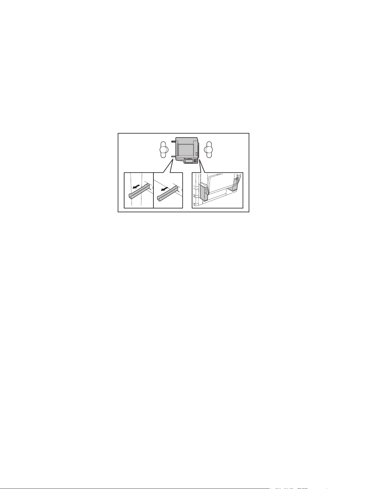
1) Transportation/Installation
- When transporting/installing the equipment, employ two persons and be sure to hold the posi-
tions as shown in the figure.
The equipment is quite heavy and weighs approximately 75 kg (165.34 lb.) therefore pay full
attention when handling it.
- Be sure not to hold the movable parts or units (e.g. the control panel, ADU or RADF) when trans-
porting the equipment.
- Be sure to use a dedicated outlet with AC 110 V / 13.2 A, 115 V or 127 V / 12 A, 220-240 V or 240
V / 8 A for its power source.
- The equipment must be grounded for safety.
- Select a suitable place for installation. Avoid excessive heat, high humidity, dust, vibration and
direct sunlight.
- Provide proper ventilation since the equipment emits a slight amount of ozone.
- To insure adequate working space for the copying operation, keep a minimum clearance of 80
cm (32”) on the left, 80 cm (32”) on the right and 10 cm (4”) on the rear.
- The equipment shall be installed near the socket outlet and shall be accessible.
- Be sure to fix and plug in the power cable securely after the installation so that no one trips over
it.
07/11

2) General Precautions at Service
- Be sure to turn the power OFF and unplug the power cable during service (except for the service
should be done with the power turned ON).
- Unplug the power cable and clean the area around the prongs of the plug and socket outlet once
a year or more. A fire may occur when dust lies on this area.
- When the parts are disassembled, reassembly is the reverse of disassembly unless otherwise
noted in this manual or other related documents. Be careful not to install small parts such as
screws, washers, pins, E-rings, star washers in the wrong places.
- Basically, the equipment should not be operated with any parts removed or disassembled.
- The PC board must be stored in an anti-electrostatic bag and handled carefully using a wristband
since the ICs on it may be damaged due to static electricity.
Caution: Before using the wristband, unplug the power cable of the equipment and
make sure that there are no charged objects which are not insulated in the
vicinity.
- Avoid expose to laser beam during service. This equipment uses a laser diode. Be sure not to
expose your eyes to the laser beam. Do not insert reflecting parts or tools such as a screwdriver
on the laser beam path. Remove all reflecting metals such as watches, rings, etc. before starting
service.
- Be sure not to touch high-temperature sections such as the exposure lamp, fuser unit, damp
heater and areas around them.
- Be sure not to touch high-voltage sections such as the chargers, developer, high-voltage trans-
former, exposure lamp control inverter, inverter for the LCD backlight and power supply unit.
Especially, the board of these components should not be touched since the electric charge may
remain in the capacitors, etc. on them even after the power is turned OFF.
- Make sure that the equipment will not operate before touching potentially dangerous places (e.g.
rotating/operating sections such as gears, belts pulleys, fans and laser beam exit of the laser
optical unit).
- Be careful when removing the covers since there might be the parts with very sharp edges
underneath.
- When servicing the equipment with the power turned ON, be sure not to touch live sections and
rotating/operating sections. Avoid exposing your eyes to laser beam.
- Use designated jigs and tools.
- Use recommended measuring instruments or equivalents.
- Return the equipment to the original state and check the operation when the service is finished.
- Be very careful to treat the touch panel gently and never hit it. Breaking the surface could cause
malfunctions.
3) Important Service Parts for Safety
- The breaker, door switch, fuse, thermostat, thermofuse, thermistor, batteries, IC-RAMs including
lithium batteries, etc. are particularly important for safety. Be sure to handle/install them properly.
If these parts are short-circuited and their functions become ineffective, they may result in fatal
accidents such as burnout. Do not allow a short-circuit or do not use the parts not recommended
by Toshiba TEC Corporation.
4) Cautionary Labels
- During servicing, be sure to check the rating plate and cautionary labels such as “Unplug the
power cable during service”, “CAUTION. HOT”, “CAUTION. HIGH VOLTAGE”, “CAUTION.
LASER BEAM”, etc. to see if there is any dirt on their surface and if they are properly stuck to the
equipment.
06/09

5) Disposal of the Equipment, Supplies, Packing Materials, Used Batteries and IC-RAMs
- Regarding the recovery and disposal of the equipment, supplies, packing materials, used batter-
ies and IC-RAMs including lithium batteries, follow the relevant local regulations or rules.
Caution:
Dispose of used batteries and IC-RAMs including lithium batteries according to this manual.
Attention:
Se débarrasser de batteries et IC-RAMs usés y compris les batteries en lithium selon ce manuel.
Vorsicht:
Entsorgung der gebrauchten Batterien und IC-RAMs (inclusive der Lithium-Batterie) nach diesem Handbuch.
05/11


CONTENTS
1. SPECIFICATIONS / ACCESSORIES / OPTIONS / SUPPLIES ................................... 1-1
1.1 Specifications....................................................................................................................... 1-1
1.2 Accessories ......................................................................................................................... 1-6
1.3 Options ................................................................................................................................ 1-7
1.3.1 e-STUDIO200L/230/230L/280/280S ........................................................................ 1-7
1.3.2 e-STUDIO202L/203L/232/232S/233/282/282S/283/283S ....................................... 1-8
1.4 Supplies............................................................................................................................. 1-10
1.4.1 e-STUDIO200L/230/230L/280/280S ...................................................................... 1-10
1.4.2 e-STUDIO202L/232/232S/282/282S ...................................................................... 1-10
1.4.3 STUDIO203L/233/283/283S .................................................................................. 1-10
1.5 System List ........................................................................................................................ 1-11
1.5.1 e-STUDIO200L/230/230L/280/280S ...................................................................... 1-11
1.5.2 e-STUDIO202L/203L/232/232S/233/282/282S/283/283S ..................................... 1-17
2. ERROR CODE AND SELF-DIAGNOSTIC MODE........................................................ 2-1
2.1 Error Code List..................................................................................................................... 2-1
2.1.1 Jam........................................................................................................................... 2-1
2.1.2 Service call ...............................................................................................................2-7
2.1.3 Error in Internet FAX / Scanning Function.............................................................. 2-10
2.1.4 Printer function error............................................................................................... 2-20
2.2 Self-diagnosis Modes ........................................................................................................ 2-23
2.2.1 Input check (Test mode 03) (e-STUDIO200L/230/280).......................................... 2-25
2.2.2 Input check (Test mode 03) (e-STUDIO202L/203L/232/233/282/283)................... 2-32
2.2.3 Output check (test mode 03) .................................................................................. 2-40
2.2.4 Test print mode (test mode 04) .............................................................................. 2-43
2.2.5 Adjustment mode (05) (e-STUDIO200L/230/280) .................................................. 2-44
2.2.6 Adjustment mode (05) (e-STUDIO202L/203L/232/233/282/283) ........................... 2-64
2.2.7 Setting mode (08) (e-STUDIO200L/230/280)......................................................... 2-84
2.2.8 Setting mode (08) (e-STUDIO202L/203L/232/233/282/283)................................ 2-153
2.2.9 Pixel counter......................................................................................................... 2-262
2.2.10 Classification List of Adjustment Mode (05) / Setting Mode (08)
(e-STUDIO200L/230/280) .................................................................................... 2-272
2.2.11 Classification List of Adjustment Mode (05) / Setting Mode (08)
(e-STUDIO202L/203L/232/233/282/283) ............................................................. 2-276
3. ADJUSTMENT ..............................................................................................................3-1
3.1 Adjustment of Auto-Toner Sensor ....................................................................................... 3-1
3.2 Image Dimensional Adjustment........................................................................................... 3-3
3.2.1 General description .................................................................................................. 3-3
3.2.2 Paper alignment at the registration roller ................................................................. 3-5
3.2.3 Printer related adjustment ........................................................................................ 3-7
3.2.4 Scanner related adjustment ................................................................................... 3-12
3.3 Image Quality Adjustment (Copying Function) .................................................................. 3-21
3.3.1 Density adjustment ................................................................................................. 3-21
3.3.2 Gamma slope adjustment ...................................................................................... 3-22
3.3.3 Sharpness adjustment............................................................................................ 3-23
3.3.4 Setting range correction ......................................................................................... 3-24
3.3.5 Setting range correction (Adjustment of background peak) ................................... 3-24
3.3.6 Adjustment of smudged/faint text ........................................................................... 3-25
3.3.7 Gamma balance adjustment < e-STUDIO 202L/203L/232/233/282/283 > ............ 3-25
3.3.8 Adjustment of image density .................................................................................. 3-26
3.4 Image Quality Adjustment (Printing Function) ................................................................... 3-27
3.4.1 Adjustment of smudged/faint text ........................................................................... 3-27
© 2004 - 2007 TOSHIBA TEC CORPORATION All rights reserved e-STUDIO200L/202L/203L/230/232/233/280/282/283
1
05/12
CONTENTS

3.4.2 Adjustment of image density .................................................................................. 3-28
3.5 Image Quality Adjustment (Scanning Function) ................................................................ 3-29
3.5.1 Density adjustment ................................................................................................. 3-29
3.5.2 Sharpness adjustment............................................................................................ 3-30
3.5.3 Setting range correction ......................................................................................... 3-31
3.5.4 Setting range correction (Adjustment of background peak) ................................... 3-32
3.5.5 Setting range correction (Adjustment of text peak) ................................................ 3-32
3.6 Adjustment of High-Voltage Transformer .......................................................................... 3-33
3.6.1 Adjustment ............................................................................................................. 3-33
3.6.2 Precautions ............................................................................................................ 3-39
3.7 Adjustment of the Scanner Section ................................................................................... 3-41
3.7.1 Carriages ................................................................................................................ 3-41
3.7.2 Lens unit................................................................................................................. 3-46
3.8 Adjustment of the Paper Feeding System ......................................................................... 3-49
3.8.1 Sheet sideways deviation caused by paper feeding .............................................. 3-49
3.9 Adjustment of Developer Unit ............................................................................................ 3-50
3.9.1 Doctor-to-sleeve gap .............................................................................................. 3-50
3.10 Adjustment of the RADF (MR-3016).................................................................................. 3-53
3.10.1 Adjustment of RADF position ................................................................................. 3-53
3.10.2 Adjustment of RADF height .................................................................................... 3-57
3.10.3 Adjustment of skew ................................................................................................ 3-59
3.10.4 Automatic adjustment of sensors and initialization of EEPROM ............................ 3-61
3.10.5 Adjustment of aligning ............................................................................................ 3-62
3.10.6 Adjustment of aligning at reversing ........................................................................ 3-63
3.10.7 Adjustment of reverse solenoid .............................................................................. 3-64
3.10.8 Adjustment of RADF opening/closing switch.......................................................... 3-66
3.10.9 Adjustment of RADF opening/closing sensor ......................................................... 3-67
3.10.10Adjustment of tray volume ..................................................................................... 3-68
3.11 Adjustment of the RADF (MR-3020).................................................................................. 3-69
3.11.1 Adjustment of RADF Position ................................................................................. 3-69
3.11.2 Adjustment of RADF Height ................................................................................... 3-74
3.11.3 Adjustment of Skew................................................................................................ 3-76
3.11.4 Adjustment of the Leading Edge Position .............................................................. 3-79
3.11.5 Adjustment of Horizontal Position .......................................................................... 3-80
3.11.6 Adjustment of Copy Ratio....................................................................................... 3-82
3.11.7 Adjustment of RADF Opening/Closing Sensor....................................................... 3-83
3.12 Adjustment of the Finisher (MJ-1022)................................................................................ 3-84
3.12.1 Adjusting the jogging plate width............................................................................ 3-84
3.12.2 Adjusting the angle of the jogging plate ................................................................. 3-86
3.12.3 Adjusting the overlap of the sensor flag ................................................................. 3-87
3.12.4 Adjusting the tension of the stack processing motor belt ....................................... 3-88
3.12.5 Releasing the stack tray guide lever fixing plate .................................................... 3-90
3.12.6 Adjustment of the upper tray angle ........................................................................ 3-91
3.12.7 DIP switch functions ............................................................................................... 3-93
3.13 Adjustment of the Finisher (MJ-1025)................................................................................ 3-95
3.13.1 Adjusting the folding position (Electrical system (Finisher/Saddle unit)) ................3-95
3.13.2 Adjusting the sensor output (Electrical system (Puncher unit; option)) .................. 3-96
3.13.3 Registering the number of punch hole
(Electrical system (Puncher unit; option))............................................................... 3-97
3.13.4 After replacing the EEP-ROM
(IC1002) (Electrical system (Puncher unit; option))................................................ 3-98
3.14 Key Copy Counter (MU-8, MU-10) .................................................................................... 3-99
3.15 Adjustment of Dogleg ...................................................................................................... 3-101
4. PREVENTIVE MAINTENANCE (PM)............................................................................ 4-1
4.1 PM Support Mode................................................................................................................ 4-1
e-STUDIO200L/202L/203L/230/232/233/280/282/283 © 2004 - 2007 TOSHIBA TEC CORPORATION All rights reserved
CONTENTS
2

4.1.1 General description .................................................................................................. 4-1
4.1.2 Operational flow and operational screen .................................................................. 4-1
4.1.3 Work flow of parts replacement ................................................................................ 4-6
4.2 General Descriptions for PM Procedure.............................................................................. 4-7
4.3 Operational Items in Overhauling ........................................................................................ 4-8
4.4 Preventive Maintenance Checklist....................................................................................... 4-9
4.5 PM KIT............................................................................................................................... 4-25
4.6 Jig List ............................................................................................................................... 4-26
4.7 Grease List ........................................................................................................................ 4-27
4.8 Precautions for Storing and Handling Supplies ................................................................. 4-28
4.8.1 Precautions for storing TOSHIBA supplies ............................................................ 4-28
4.8.2 Checking and cleaning of photoconductive drum................................................... 4-29
4.8.3 Checking and cleaning of drum cleaning blade...................................................... 4-30
4.8.4 Checking and cleaning of fuser roller and pressure roller ...................................... 4-30
4.8.5 Checking and replacing the cleaning roller ............................................................ 4-30
5. TROUBLESHOOTING ..................................................................................................5-1
5.1 Diagnosis and Prescription for Each Error Code ................................................................. 5-1
5.1.1 Paper transport jam .................................................................................................. 5-1
5.1.2 Paper misfeeding ................................................................................................... 5-15
5.1.3 Cover open jam ...................................................................................................... 5-22
5.1.4 Transport jam (RADF) ............................................................................................ 5-28
5.1.5 Finisher jam............................................................................................................ 5-35
5.1.6 Drive system related service call ............................................................................ 5-47
5.1.7 Paper feeding system related service call .............................................................. 5-48
5.1.8 Scanning system related service call ..................................................................... 5-54
5.1.9 Fuser unit related service call................................................................................. 5-56
5.1.10 Communication related service call........................................................................ 5-58
5.1.11 RADF related service call (MR-3016)..................................................................... 5-59
5.1.12 RADF related service call (MR-3020)..................................................................... 5-60
5.1.13 Laser optical unit related service call ..................................................................... 5-60
5.1.14 Finisher related service call.................................................................................... 5-61
5.1.15 Service call for others............................................................................................. 5-76
5.1.16 Error in Internet FAX / Scanning Function.............................................................. 5-79
5.2 Troubleshooting for the Image........................................................................................... 5-94
5.3 Replacement of PC Boards and HDD ............................................................................. 5-116
5.3.1 Replacing HDD..................................................................................................... 5-116
5.3.2 Replacing SYS board ........................................................................................... 5-119
5.3.3 Caution when Data overwrite kit (GP-1050/1060) is installed ............................. 5-121
5.3.4 HDD information display....................................................................................... 5-121
5.3.5 Replacing or clearing NVRAM.............................................................................. 5-124
6. FIRMWARE UPDATING ...............................................................................................6-1
6.1 Firmware Updating with Download Jig (e-STUDIO200L/230/280) ...................................... 6-3
6.1.1 PWA-DWNLD-350-JIG2 (48 MB) ............................................................................. 6-5
6.1.2 PWA-DWNLD-350-JIG1 (16 MB) ........................................................................... 6-12
6.1.3 Writing the data to the download jig (PWA-DWNLD-350-JIG) ............................... 6-21
6.1.4 K-PWA-DLM-320.................................................................................................... 6-22
6.2 Firmware Updating with Download Jig (e-STUDIO202L/203L/232/233/282/283) ............. 6-32
6.2.1 PWA-DWNLD-350-JIG2 (48 MB) ........................................................................... 6-34
6.2.2 Writing the data to the download jig (PWA-DWNLD-350-JIG) ............................... 6-48
6.2.3 K-PWA-DLM-320.................................................................................................... 6-50
6.3 Firmware Updating with FSMS (Field Service Manager) (e-STUDIO200L/230/280) ........ 6-60
6.4 Firmware Updating with USB Storage Device (e-STUDIO200L/230/280)......................... 6-72
6.5 Firmware Updating with USB Storage Device
(e-STUDIO202L/203L/232/233/282/283)........................................................................... 6-86
© 2004 - 2007 TOSHIBA TEC CORPORATION All rights reserved e-STUDIO200L/202L/203L/230/232/233/280/282/283
3
06/09
CONTENTS

6.6 Appendix.......................................................................................................................... 6-109
6.6.1 e-STUDIO200L/230/280....................................................................................... 6-109
6.6.2 e-STUDIO202L/203L/232/233/282/283................................................................ 6-110
7. POWER SUPPLY UNIT ................................................................................................ 7-1
7.1 Output Channel ................................................................................................................... 7-1
7.2 Fuse..................................................................................................................................... 7-3
7.3 Configuration of Power Supply Unit..................................................................................... 7-4
8. REMOTE SERVICE....................................................................................................... 8-1
8.1 Auto Supply Order ............................................................................................................... 8-1
8.1.1 Outline ...................................................................................................................... 8-1
8.1.2 Setting Item .............................................................................................................. 8-2
8.1.3 Setting procedure ..................................................................................................... 8-5
8.1.4 Order Sheet Format ............................................................................................... 8-12
8.2 Service Notification............................................................................................................ 8-14
8.2.1 Outline ....................................................................................................................8-14
8.2.2 Setting (e-STUDIO200L/230/280) .......................................................................... 8-14
8.2.3 Items to be notified (e-STUDIO200L/230/280) ....................................................... 8-19
8.2.4 Setting (e-STUDIO202L/203L/232/233/282/283) ................................................... 8-24
8.2.5 Items to be notified (e-STUDIO202L/203L/232/233/282/283) ................................ 8-30
9. DATA CLONING with USB STORAGE DEVICE
(e-STUDIO202L/203L/232/233/282/283) ...................................................................... 9-1
10. WIRE HARNESS CONNECTION DIAGRAMS ........................................................... 10-1
10.1 AC Wire Harness ............................................................................................................... 10-1
10.2 DC Wire Harness (e-STUDIO200L/230/230L/280/280S) .......................................... Appendix
10.3 Connector Table (e-STUDIO200L/230/230L/280/280S)............................................ Appendix
10.4 DC Wire Harness (e-STUDIO202L/232/282)............................................................. Appendix
10.5 Connector Table (e-STUDIO202L/232/282) .............................................................. Appendix
e-STUDIO200L/202L/203L/230/232/233/280/282/283 © 2004 - 2007 TOSHIBA TEC CORPORATION All rights reserved
CONTENTS
4
05/11

1. SPECIFICATIONS / ACCESSORIES /
OPTIONS / SUPPLIES
2. ERROR CODE AND SELF-DIAGNOSTIC
MODE
3. ADJUSTMENT
4. PREVENTIVE MAINTENANCE (PM)
5. TROUBLESHOOTING
1
2
3
4
5
6. FIRMWARE UPDATING
7. POWER SUPPLY UNIT
8. REMOTE SERVICE
9. DATA CLONING with USB STORAGE DEVICE
(e-STUDIO202L/203L/232/233/282/283)
10. WIRE HARNESS CONNECTION DIAGRAMS
6
7
8
9
10

1. SPECIFICATIONS / ACCESSORIES / OPTIONS / SUPPLIES
1.1 Specifications
Values in { } are for e-STUDIO200L/202L/203L and values in [ ] are for e- STUDIO280/280S/282/
282S/283/283S in case that the specification is different among e-STUDIO200L/202L/203L,
e-STUDIO230/230L/232/232S/233 and e-STUDIO280/280S/282/282S/283/283S.
Copy process Indirect electrophotographic process (dry)
Type Desktop type (console type: when paper feed pedestal (PFP) and large
capacity feeder (LCF) are installed)
Original table Fixed type (the left rear corner used as guide to place originals)
Accepted originals Sheet, book and 3-dimensional object. The reversing automatic document
feeder (RADF) only accepts paper which are not pasted or stapled. Carbon
paper are not acceptable either.
Maximum size: A3/LD
Single - sided original Double - sided original
MR-3016
MR-3018
50 ~ 127 g/m
35 ~ 157 g/m
2
(13 lb. Bond - 34 lb. Bond) 50 ~ 105 g/m2 (13 lb. Bond - 28 lb. Bond)
2
(9.3 lb. Bond - 58 lb. Cover) 50 ~ 157 g/m2 (13 lb. Bond - 58 lb. Cover)
1
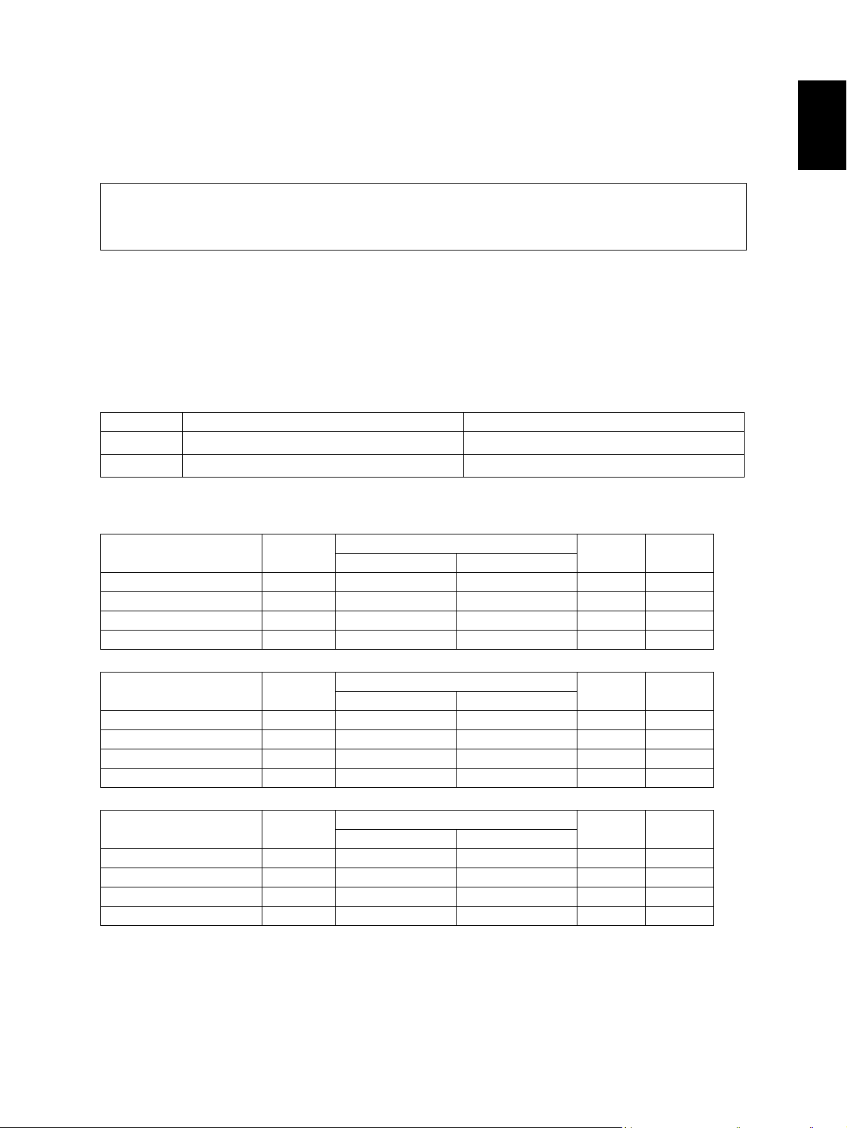
Copy speed (Copies/min.)
e-STUDIO200L/202L/203L
Paper size Drawer
A4, LT, B5, A5-R, ST-R 20 20 16 20 20
A4-R, B5-R, LT-R 19 19 16 19 –
B4, LG 18 18 16 18 –
A3, LD 16 16 16 16 –
Size specified Size not specified
Bypass feed
PFP LCF
e-STUDIO230/230L/232/232S/233
Paper size Drawer
A4, LT, B5, A5-R, ST-R 23 23 16 23 23
A4-R, B5-R, LT-R 21.5 21.5 16 21.5 –
B4, LG 18 18 16 18 –
A3, LD 16 16 16 16 –
Size specified Size not specified
Bypass feed
PFP LCF
e-STUDIO280/280S/282/282S/283/283S
Paper size Drawer
A4, LT, B5, A5-R, ST-R 28 28 16 28 28
A4-R, B5-R, LT-R 21.5 21.5 16 21.5 –
B4, LG 18 18 16 18 –
A3, LD 16 16 16 16 –
Size specified Size not specified
Bypass feed
PFP LCF
* “–” means “Not acceptable”.
* The copy speed in the above table are available when originals are manually placed for single side,
multiple copying.
© 2004 - 2007 TOSHIBA TEC CORPORATION All rights reserved e-STUDIO200L/202L/203L/230/232/233/280/282/283
1 - 1
07/11
SPECIFICATIONS / ACCESSORIES / OPTIONS / SUPPLIES
* When the RADF is used, the copy speed of {20}23[28] sheets per minute is only available under the
following conditions:
• Original/Mode: Single side original/A4/LT size. APS/automatic density are not selected.
• Number of sheets: {20}23[28] or more.
• Reproduction ratio: 100%
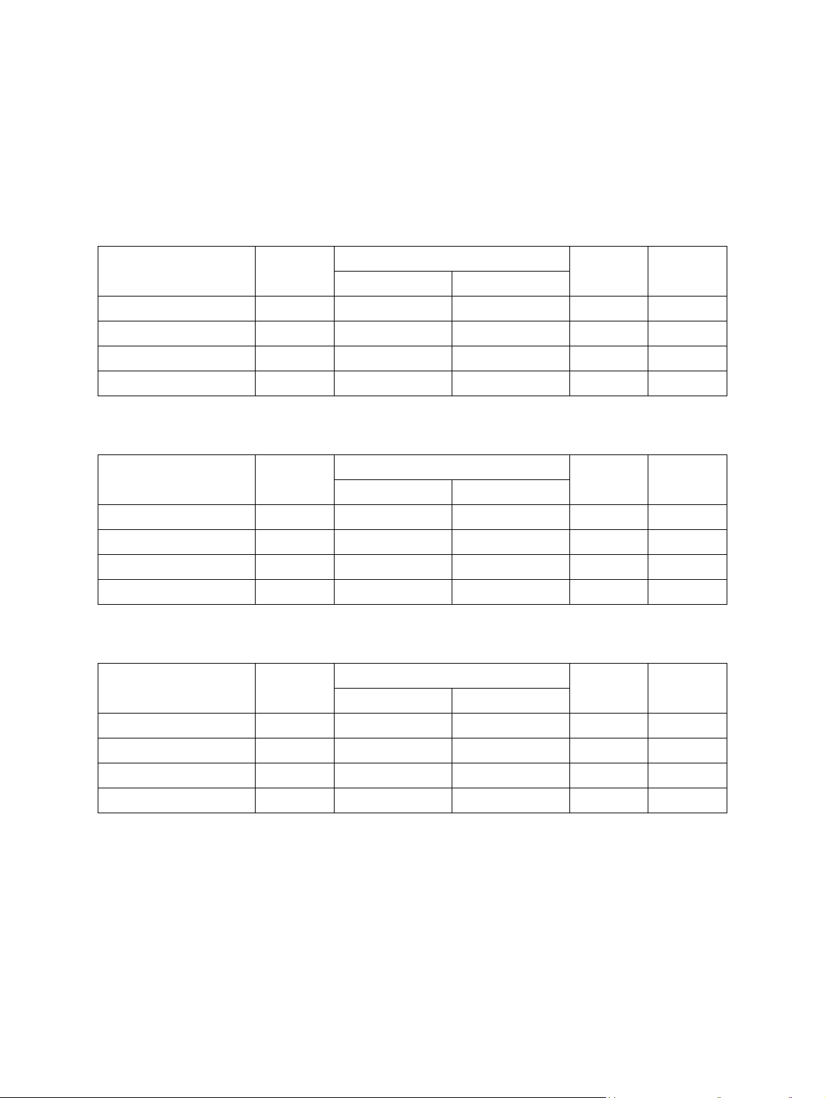
Copy speed for thick paper (Copies/min.)
e-STUDIO200L/202L/203L/230/232/233/280/282/283 series
2
Thick 1 (81 g/m
Paper size Drawer
A4, LT, B5, A5-R, ST-R {20} 23 [27] {20} 23 [27] {15} 16 [16] {20} 23 [27] {20} 23 [27]
A4-R, B5-R, LT-R {19} 21 [21] {19} 21 [21] {15} 16 [16] {19} 21 [21] {-} - [-]
B4, LG {18} 18 [18] {18} 18 [18] {15} 16 [16] {18} 18 [18] {-} - [-]
A3, LD {15} 16 [16] {15} 16 [16] {15} 16 [16] {15} 16 [16] {-} - [-]
Thick 2 (106 g/m
Paper size Drawer
to 105 g/m2, 21.3 lb. Bond to 28 lb. Bond)
Bypass feed
Size specified Size not specified
2
to 163 g/m2, 28 lb. Bond to 90 lb. Index)
Bypass feed
Size specified Size not specified
PFP LCF
PFP LCF
A4, LT, B5, A5-R, ST-R {-} - [-] {20} 23 [27] {15} 16 [16] {-} - [-] {-} - [-]
A4-R, B5-R, LT-R {-} - [-] {19} 21 [21] {15} 16 [16] {-} - [-] {-} - [-]
B4, LG {-} - [-] {18} 18 [18] {15} 16 [16] {-} - [-] {-} - [-]
A3, LD {-} - [-] {15} 16 [16] {15} 16 [16] {-} - [-] {-} - [-]
2
Thick 3 (164 g/m
Paper size Drawer
A4, LT, B5, A5-R, ST-R {-} - [-] {20} 23 [27] {15} 16 [16] {-} - [-] {-} - [-]
A4-R, B5-R, LT-R {-} - [-] {19} 21 [21] {15} 16 [16] {-} - [-] {-} - [-]
B4, LG {-} - [-] {18} 18 [18] {15} 16 [16] {-} - [-] {-} - [-]
A3, LD {-} - [-] {15} 16 [16] {15} 16 [16] {-} - [-] {-} - [-]
to 209 g/m2, 90 lb. Index to 115.7 lb. Index)
Bypass feed
PFP LCF
Size specified Size not specified
* Only A4/LT size is available for the LCF.
* The tolerance is within ±2.
e-STUDIO200L/202L/203L/230/232/233/280/282/283 © 2004 - 2007 TOSHIBA TEC CORPORATION All rights reserved
SPECIFICATIONS / ACCESSORIES / OPTIONS / SUPPLIES
1 - 2
07/11
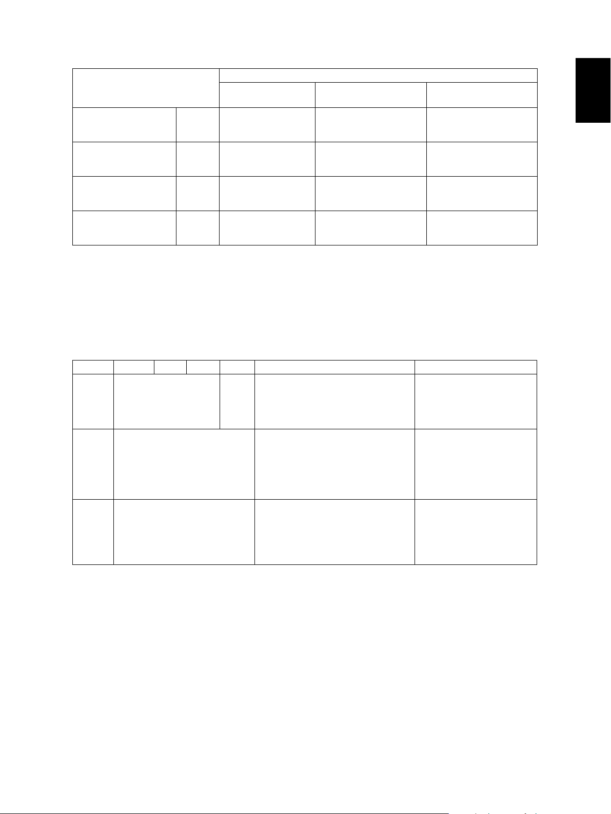
* System copy speed
Sec.
Copy mode
Single-sided originals
↓
Single-sided copies
Single-sided originals
↓
Double-sided copies
Double-sided originals
↓
Double-sided copies
Double-sided originals
↓
Single-sided copies
1 set
3 sets
5 sets
1 set
3 sets
5 sets
1 set
3 sets
5 sets
1 set
3 sets
5 sets
e-STUDIO200L/202/
203L
34.18
95.53
154.28
37.44
96.81
155.54
70.26
188.48
306.64
64.65
184.73
302.58
e-STUDIO230/230L/
232/232S/233
31.5
84.8
136.2
34.5
85.9
137.4
64.8
167.7
270.6
57.8
163.1
266.1
e-STUDIO280/280S/
282/282S/283/283S
27.6
72.2
114 .0
31.6
73.4
116 .4
58.9
143.8
228.5
50.5
137.3
222.1
* The system copy speed, including scanning time, is available when 10 sheets of A4/LT size original
are set on RADF and one of the copy modes in the above table is selected. The period of time from
pressing [START] to the paper exit completely out of the equipment based on the actually measured
value.
* Upper drawer is selected and copying is at the non-sort mode.
* Automatic copy density, APS/AMS are turned off.
* Finisher is not installed.
Copy paper
Drawer ADU PFP LCF Bypass copy Remarks
Size A3 to A5-R, LD to ST-R,
FOLIO, COMPUTER,
13"LG, 8.5" x 8.5", 8K,
16K, 16K-R
Weight
Special
paper
64 to 105 g/m
17 to 28 lb. Bond
– Tracing paper, labels,
A4, LT A3 to A5-R, LD to ST-R, FOLIO,
COMPUTER, 13"LG, 8.5" x 8.5", 8K,
16K, 16K-R
(Non-standard or user-specified
sizes can be set.)
2
64 to 209 g/m
Index
(Continuous feeding)
50 to 209 g/m2, 13 lb. Bond to 110 lb.
Index
(Single paper feeding)
OHP film
(thickness: 80 µm or thicker),
tab paper, envelope
(COM10, Monarch, DL, CHO-3,
YOU-4)
2
, 17 lb. Bond to 110 lb.
These special papers recommended by Toshiba Tec
CHO-3: 92 mm x 235 mm
YOU-4: 105 mm x 235 mm
1
First copy time ......................... Approx. 5.4 sec. or less
(A4/LT, upper drawer, 100%, original placed manually)
Warming-up time ..................... Approx. 25 sec. (temperature: 20°C)
Multiple copying....................... Up to 999 copies; Key in set numbers
Reproduction ratio ................... Actual ratio: 100±0.5%
Zooming: 25 to 400% in increments of 1%
(25 to 200% when using RADF)
Resolution/Gradation............... Scanning: 600 dpi x 600 dpi
Printing: Equivalent to 2400 dpi x 600 dpi
Gradation: 256 steps
© 2004 - 2007 TOSHIBA TEC CORPORATION All rights reserved e-STUDIO200L/202L/203L/230/232/233/280/282/283
1 - 3
07/11
SPECIFICATIONS / ACCESSORIES / OPTIONS / SUPPLIES

Eliminated portion.................... Leading edges: 3.0±2.0 mm, Side/trailing edges: 2.0±2.0 mm (copy)
Leading / trailing edges: 5.0±2.0 mm, Side edges: 5.0±2.0 mm (print)
Paper feeding .......................... Standard drawers:
1 or 2 drawers (stack height 60.5 mm, equivalent to 550 sheets;
2
64 to 80 g/m
(17 to 22 lb. Bond)): Depends on destinations or
versions.
PFP:
Option (One drawer or two: stack height 60.5 mm, equivalent to
2
550 sheets; 64 to 80 g/m
(17 to 22 lb. Bond))
LCF:
Option (Stack height 137.5 mm x 2: equivalent to 2500 sheets;
2
64 to 80 g/m
(17 to 22 lb. Bond))
Bypass feeding:
2
Stack height 11 mm: equivalent to 100 sheets; 64 to 80 g/m
(17
to 22 lb. Bond)
Capacity of originals in the reversing automatic document feeder (Option)
.................................................. A3 to A5-R, LD to ST-R:
2
100 sheets / 80 g/m
(Stack height 16 mm or less)
Automatic duplexing unit (ADU is available as standard equipment for some destinations or versions.)
.................................................. Stackless, Switchback type
Toner supply............................ Automatic toner density detection/supply
Toner cartridge replacing method (There is a recovered toner supply
mechanism.)
Density control......................... Automatic density mode and manual density mode selectable in 11
steps
Weight ..................................... Approximately 75 kg (165.34 lb.): e-STUDIO200L/230/230L/280/280S
Approximately 77 kg (169.75 lb.): e-STUDIO202L/203L/232/233/232S/
282/282S/283 (include the developer material and drum) (The ADU
and Drawer module are installed.)
Power requirements ................ AC 110 V / 13.2 A, 115 V or 127 V / 12 A
220-240 V or 240 V / 8 A (50/60 Hz)
* The acceptable value of each voltage is ±10%.
Power consumption................. 1.5 kW or less (115 V series, 200 V series)
* The electric power is supplied to the RADF, (ADU), Finisher, Job Separator, Offset Tray, PFP and
LCF through the equipment.
Total counter............................ Electronical counter
e-STUDIO200L/202L/203L/230/232/233/280/282/283 © 2004 - 2007 TOSHIBA TEC CORPORATION All rights reserved
SPECIFICATIONS / ACCESSORIES / OPTIONS / SUPPLIES
1 - 4
07/11
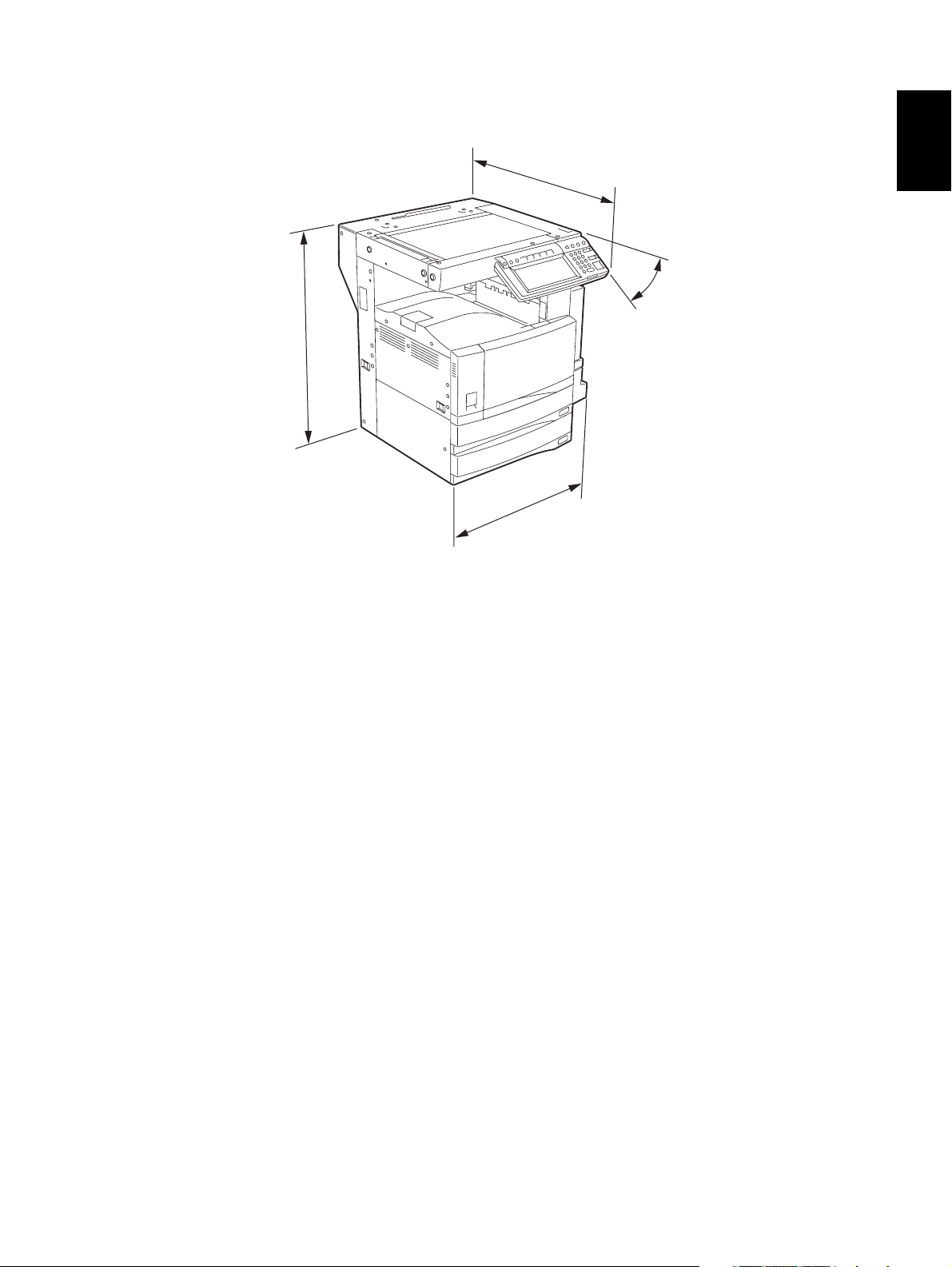
Dimensions of the equipment...................... See the figure below (W 637 x D 719 x H 739 (mm))
* When the tilt angle of the control panel is 45 degrees.
719
45°
739
637
1
Fig. 1-1
© 2004 - 2007 TOSHIBA TEC CORPORATION All rights reserved e-STUDIO200L/202L/203L/230/232/233/280/282/283
1 - 5
04/09
SPECIFICATIONS / ACCESSORIES / OPTIONS / SUPPLIES

1.2 Accessories
Unpacking/setup instruction 1 set
Operator’s manual 3 pcs. (except for MJD)
Operator's manual pocket 1 pc.
Power cable 1 pc.
Warranty sheet 1 pc. (for NAD)
Setup report 1 set (for NAD and MJD)
Customer satisfaction card 1 pc. (for MJD)
Drum (installed inside of the equipment) 1 pc.
Toner cartridge 1 pc. (except for NAD, MJD)
Developer material 1 pc. (except for NAD, MJD)
Control panel stopper 1 pc.
Blind seal 1 pc.
Rubber plug 5 pcs.
CD-ROM
Transfer charger wire cleaner
(installed inside of the transfer cover)
Paper stopper
Stopper bracket
*1
*1
4 pcs.
1 pc.
1 pc.
1 pc.
*2
Machine version
NAD: North America
ARD: Argentina
ASD: Central and South America / Hong Kong
AUD: Australia
MJD: Europe
ASU: Asia
SAD: Saudi Arabia
IRD: Iran
CND: China
TWD: Taiwan
JPD: Japan
KRD: Korea
*1: e-STUDIO200L/230/230L/280/280S only
*2: In e-STUDIO202L/203L/232/232S/233/282/282S/283, 2 discs are included.
e-STUDIO200L/202L/203L/230/232/233/280/282/283 © 2004 - 2007 TOSHIBA TEC CORPORATION All rights reserved
SPECIFICATIONS / ACCESSORIES / OPTIONS / SUPPLIES
1 - 6
07/11
1.3 Options
1.3.1 e-STUDIO200L/230/230L/280/280S
Platen Cover KA-3511 PC/PC-C
Reversing Automatic Document Feeder (RADF) MR-3016
Drawer Module MY-1021/-C
Paper Feed Pedestal (PFP) KD-1011/-C
Large Capacity Feeder (LCF) KD-1012 A4/LT/A4-C
Finisher (Hanging type) MJ-1022/-C
Saddle stitch Finisher MJ-1025/-C
Hole Punch Unit
MJ-6005 N/E/F/S
Staple Cartridge STAPLE-1600 (for MJ-1022)
STAPLE-2000 (for MJ-1025)
Bridge Kit KN-3520/-C
Job Separator MJ-5004/-C
Offset Tray MJ-5005/-C
Key copy Counter, Key copy counter socket MU-8, MU-10
Work Tray KK-3511
Damp Heater MF-2320 U/E
Fax Board GD-1150 NA/AU/EU/TW/C/AS
2nd Line for Fax Board GD-1160 NA/EU/TW/C
Wireless LAN Adapter GN-1010
PCI Slot GO-1040/C
Scrambler Board GP-1030
Printer Kit GM-1020/GM-1030
Printer/Scanner Kit GM-2020/GM-2030
Scanner upgrade Kit GM-3020/GM-3030
Parallel interface kit GF-1140
Desk MH-1700
Harness kit for coin controller GQ-1020
Automatic Duplexing Unit (ADU) MD-0102
Slot cover KE-2330
NIC board GF-1150
Data overwrite kit GP-1050
*1
1
* 1) N: North America E: Europe F: France S: Sweden
Notes:
• The bridge unit (KN-3520) is necessary for installation of the finisher (MJ-1022, MJ-1025).
• The finisher (MJ-1025) is necessary for installation of the hole punch unit (MJ-6005N/E/F/S).
• The PCI slot (GO-1040) is necessary for installation of the scrambler board (GP-1030) and
parallel interface kit (GF-1140).
• GM-1030/GM-2030/GM-3030 are exclusive for e-STUDIO200L.
They do not operate with e-STUDIO230/230L/280/280S.
© 2004 - 2007 TOSHIBA TEC CORPORATION All rights reserved e-STUDIO200L/202L/203L/230/232/233/280/282/283
1 - 7
05/11
SPECIFICATIONS / ACCESSORIES / OPTIONS / SUPPLIES

1.3.2 e-STUDIO202L/203L/232/232S/233/282/282S/283/283S
Platen Cover KA-3511PC/-C
Reversing Automatic Document Feeder (RADF) MR-3020
Automatic Duplexing Unit (ADU) MD-0102
Drawer module MY-1021/-C
Slot cover KE-2330
Paper Feed Pedestal (PFP) KD-1011/-C
Large Capacity Feeder (LCF) KD-1012LT/A4/A4-C
Finisher (Hanging type) MJ-1022/-C
Finisher (Console saddle stitcher type) MJ-1025
Hole punch unit (for MJ-1025)
MJ-6005N/E/F/S
Staple cartridge STAPLE-1600 (for MJ-1022)
STAPLE-2000 (for MJ-1025)
Bridge kit KN-3520/-C
Job separator MJ-5004/-C
Offset tray MJ-5005/-C
Work tray KK-3511/-C
Damp heater MF-3520U/E
Fax board GD-1150NA/EU/AU/AS/C/TW
2nd line for fax board GD-1160NA/EU-N/C/TW
Printer kit GM-1070/1071/1080U/1081U
Printer/Scanner kit GM-2070/2071/2080U/2081U
Scanner kit GM-4070/GM-4080U
Printer ELK GM-1130 (e-STUDIO232/232S/233/
282/282S/283/283S)
GM-1140U (e-STUDIO202L/203L)
Printer/Scanner ELK GM-2130 (e-STUDIO232/232S/233/
282/282S/283/283S)
GM-2140U (e-STUDIO202L/203L)
Scanner ELK GM-4130 (e-STUDIO232/232S/233/
282/282S/283/283S)
GM-4140U (e-STUDIO202L/203L)
Memory GC-1230
Scrambler board GP-1040
Wireless LAN module GN-1041
Bluetooth module GN-2010
Antenna GN-3010
Data overwrite kit GP-1060
PCI slot GO-1060
Desk MH-1700
Harness kit for coin controller GQ-1020
*1
* 1) N: North America E: Europe F: France S: Sweden
e-STUDIO200L/202L/203L/230/232/233/280/282/283 © 2004 - 2007 TOSHIBA TEC CORPORATION All rights reserved
SPECIFICATIONS / ACCESSORIES / OPTIONS / SUPPLIES
1 - 8
07/11

Notes:
1. The bridge kit (KN-3520) is necessary for installation of the finisher (MJ-1022 or MJ-1025).
2. The saddle stitch finisher (MJ-1025) is necessary for installation of the hole punch unit
(MJ-6005N/E/F/S).
3. The PCI slot (GO-1060) is necessary for installation of the scrambler board (GP-1040).
4. The antenna (GN-3010) is necessary to enable the wireless LAN module (GN-1041) and
Bluetooth module (GN-2010).
5. When the wireless LAN module (GN-1041) and the Bluetooth module (GN-2010) are
installed, only 1 antenna (GN-3010) can be connected to each.
6. GM-1080U / GM-2080U / GM-4080U are exclusive to e-STUDIO202L. They do not operate
with e-STUDIO232/232S/282/282S.
7. GM-1081U / GM-2081U / GM-4080U are exclusive to e-STUDIO202L/203L. They do not
operate with e-STUDIO232/232S/233/282/282S/283.
8. The Printer kit (GM-1070/1080U) or Printer/Scanner kit (MG-2070/2080U) does not have a
function for printing an XPS file.
9. To enable an XPS file to be printed by the Printer kit (GM-1071/1081U) or Printer/Scanner kit
(GM-2071/1081U), the Memory (GC-1230) is required to be installed.
10.To enable an XPS file to be printed by the Printer ELK (GM-1130/1140U) or Printer/Scanner
ELK (GM-2130/2140U), the Memory (GC-1230) is required to be installed.
1
© 2004 - 2007 TOSHIBA TEC CORPORATION All rights reserved e-STUDIO200L/202L/203L/230/232/233/280/282/283
1 - 9
07/11
SPECIFICATIONS / ACCESSORIES / OPTIONS / SUPPLIES
1.4 Supplies
1.4.1 e-STUDIO200L/230/230L/280/280S
Drum OD-1600
Toner cartridge
Developer D-2320 /C
PS-ZT2320 /T/D/C/E
* 1) T: Taiwan D: Asia C: China E: Europe NONE: North America
1.4.2 e-STUDIO202L/232/232S/282/282S
Drum OD-1600
Toner cartridge
Developer D-2340 /C
PS-ZT2340 /T/D/C/E
* 1) T: Taiwan D: Asia C: China E: Europe NONE: North America
1.4.3 STUDIO203L/233/283/283S
*1
*1
Drum OD-1600
Toner cartridge
Developer D-2340 /C
PS-ZT2840 /E
PS-ZT2340C
*1
*1
* 1) C: China E: Europe NONE: North America
e-STUDIO200L/202L/203L/230/232/233/280/282/283 © 2004 - 2007 TOSHIBA TEC CORPORATION All rights reserved
SPECIFICATIONS / ACCESSORIES / OPTIONS / SUPPLIES
1 - 10
07/11
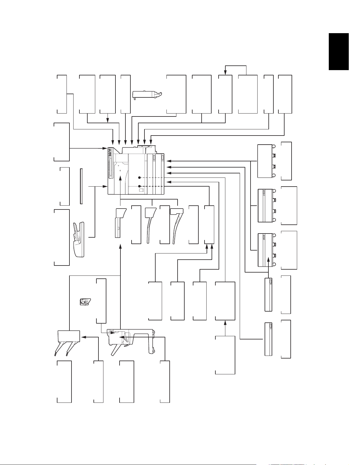
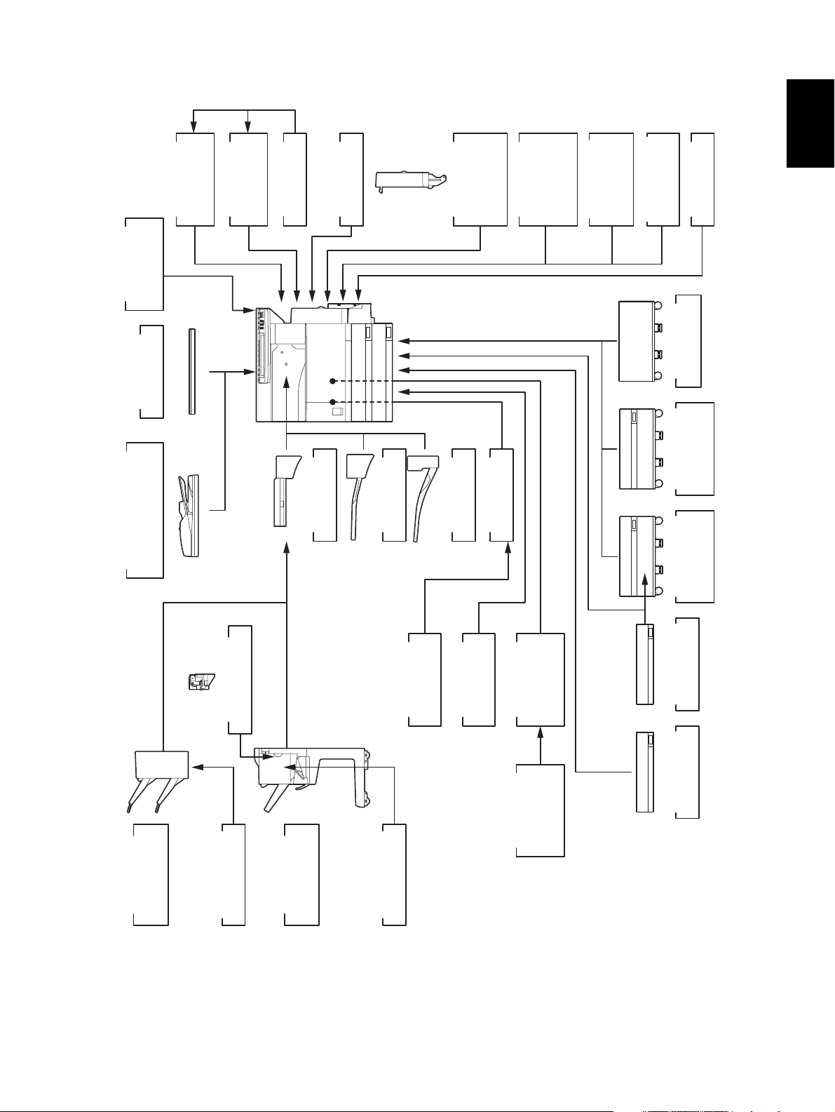
1.5 System List
1.5.1 e-STUDIO200L/230/230L/280/280S
)
KK-3511
Work Tray
GQ-1020
coin controller
Harness kit for
KA-3511
Platen Cover
)
RADF
(
MR-3016
MU-8
Counter
Key Copy
MU-10
Key Copy
Counter Socket
Damp Heater
MF-2320 U/E
KN-3520
Bridge Kit
ADU
(
MD-0102
Automatic
Duplexing Unit
MJ-5004
Job Separator
Printer/
GM-2020/
Scanner Kit
PCI Slot
MJ-5005
Offset Tray
GM-2030
Printer Kit
GO-1040
Scanner
GM-1030
GM-1020/
GM-3030
GM-3020/
Upgrade Kit
Data
GF-1150
NIC board
GP-1050
overwrite kit
Desk
MH-1700
Feeder (LCF)
Large Capacity
KD-1012 A4/LT
1
Reversing Automatic
Document Feeder
)
Finisher
MJ-1022
Hanging type
(
Hole Punch Unit
MJ-6005 N/E/F/S
STAPLE-1600
Staple Cartridge
Saddle stitch
Finisher
MJ-1025
kit
Parallel interface
Board
GF-1140
Scrambler
STAPLE-2000
Staple Cartridge
Fig. 1-2
GP-1030
Wireless LAN
Adapter
GN-1010
GD-1150
TW/C/AS
FAX Board
NA/AU/EU/
GD-1160
FAX Board
2nd Line for
NA/EU/TW/C
KD-1011
Paper Feed
Pedestal (PFP)
MY-1021
Drawer Module
KE-2330
Slot cover
© 2004 - 2007 TOSHIBA TEC CORPORATION All rights reserved e-STUDIO200L/202L/203L/230/232/233/280/282/283
SPECIFICATIONS / ACCESSORIES / OPTIONS / SUPPLIES
1 - 11
05/11

e-STUDIO280/280S
Central and
Area North America
Machine version
(destination)
NAD
(115V)
Model name e-STUDIO280 e-STUDIO280 e-STUDIO280 e-STUDIO280 e-STUDIO280
Platen cover KA-3511PC KA-3511PC KA-3511PC KA-3511PC KA-3511PC
RADF MR-3016 MR-3016 MR-3016 MR-3016 MR-3016
Drawer module
(for Equipment)
Drawer module
(for PFP)
Standard MY-1021 Standard Standard MY-1021
MY-1021 MY-1021 MY-1021 MY-1021 MY-1021
Slot cover - Standard - - KE-2330
ADU Standard MD-0102 Standard Standard MD-0102
PFP KD-1011 KD-1011 KD-1011 KD-1011 KD-1011
LCF KD-1012LT KD-1012A4 KD-1012A4 KD-1012A4 KD-1012A4
Finisher
(Hanging type)
Staple cartridge
(for MJ-1022)
MJ-1022 MJ-1022 MJ-1022 MJ-1022 MJ-1022
STAPLE-1600 STAPLE-1600 STAPLE-1600 STAPLE-1600 STAPLE-1600
Saddle stitch finisher MJ-1025 MJ-1025 MJ-1025 MJ-1025 MJ-1025
Staple cartridge
(for MJ-1025)
STAPLE-2000 STAPLE-2000 STAPLE-2000 STAPLE-2000 STAPLE-2000
Hole punch unit MJ-6005N MJ-6005E MJ-6005E MJ-6005E/F/S MJ-6005E
Bridge kit KN-3520 KN-3520 KN-3520 KN-3520 KN-3520
Job separator MJ-5004 MJ-5004 MJ-5004 MJ-5004 MJ-5004
Offset tray MJ-5005 MJ-5005 MJ-5005 MJ-5005 MJ-5005
Key copy counter MU-8 MU-8 MU-8 MU-8 MU-8
Key copy counter
socket
MU-10 MU-10 MU-10 MU-10 MU-10
Work tray KK-3511 KK-3511 KK-3511 KK-3511 KK-3511
Damp heater MF-2320U Standard Standard MF-2320E Standard
Fax board GD-1150NA GD-1150AS GD-1150AU GD-1150EU GD-1150AS
2nd line for Fax
board
Wireless LAN
adapter
GD-1160NA GD-1160EU GD-1160EU GD-1160EU GD-1160EU
GN-1010 GN-1010 GN-1010 GN-1010 GN-1010
PCI slot GO-1040 GO-1040 GO-1040 GO-1040 GO-1040
Scrambler board GP-1030 GP-1030 GP-1030 GP-1030 GP-1030
Parallel interface kit GF-1140 GF-1140 GF-1140 GF-1140 GF-1140
NIC board Standard GF-1150 Standard Standard GF-1150
Printer/Scanner kit GM-2020 GM-2020 GM-2020 GM-2020 GM-2020
Printer kit GM-1020 GM-1020 GM-1020 GM-1020 GM-1020
Scanner upgrade kit GM-3020 GM-3020 GM-3020 GM-3020 GM-3020
Desk MH-1700 MH-1700 MH-1700 MH-1700 MH-1700
Harness kit for coin
controller
GQ-1020 GQ-1020 GQ-1020 GQ-1020 GQ-1020
South America/
Hong Kong
ASD
(220-240V)
Australia Europe Asia
AUD
(220-240V)
MJD
(220-240V)
ASU
(220-240V)
e-STUDIO200L/202L/203L/230/232/233/280/282/283 © 2004 - 2007 TOSHIBA TEC CORPORATION All rights reserved
SPECIFICATIONS / ACCESSORIES / OPTIONS / SUPPLIES
1 - 12
04/09

Area Saudi Arabia Iran China Taiwan
Machine version
(destination)
SAD
(127V)
IRD
(220-240V)
CND
(220-240V)
TWD
(110V)
Model name e-STUDIO280 e-STUDIO280 e-STUDIO280S e-STUDIO280 e-STUDIO280
Platen cover KA-3511PC KA-3511PC Standard Standard KA-3511PC
RADF MR-3016 MR-3016 MR-3016 MR-3016 MR-3016
Drawer module
(for Equipment)
Drawer module
(for PFP)
MY-1021 Standard Standard Standard Standard
MY-1021 MY-1021 MY-1021 MY-1021 MY-1021
Slot cover KE-2330 - - - -
ADU MD-0102 Standard MD-0102 Standard MD-0102
PFP KD-1011 KD-1011 KD-1011 KD-1011 KD-1011
LCF KD-1012A4 KD-1012A4 KD-1012-C KD-1012-C KD-1012A4
Finisher
(Hanging type)
Staple cartridge
(for MJ-1022)
MJ-1022 MJ-1022 MJ-1022-C MJ-1022-C MJ-1022
STAPLE-1600 STAPLE-1600 STAPLE-1600 STAPLE-1600 STAPLE-1600
Saddle stitch finisher MJ-1025 MJ-1025 MJ-1025 MJ-1025 MJ-1025
Staple cartridge
(for MJ-1025)
STAPLE-2000 STAPLE-2000 STAPLE-2000 STAPLE-2000 STAPLE-2000
Hole punch unit MJ-6005E MJ-6005E MJ-6005E MJ-6005E MJ-6005E
Bridge kit KN-3520 KN-3520 KN-3520-C KN-3520-C KN-3520
Job separator MJ-5004 MJ-5004 MJ-5004-C MJ-5004-C MJ-5004
Offset tray MJ-5005 MJ-5005 MJ-5005-C MJ-5005-C MJ-5005
Key copy counter MU-8 MU-8 MU-8 MU-8 MU-8
Key copy counter
socket
MU-10 MU-10 MU-10 MU-10 MU-10
Work tray KK-3511 KK-3511 KK-3511 KK-3511 KK-3511
Damp heater Standard Standard Standard Standard Standard
Fax board GD-1150NA N/A GD-1150C GD-1150C GD-1150TW
2nd line for Fax
board
Wireless LAN
adapter
GD-1160NA N/A GD-1160C GD-1160C GD-1160TW
GN-1010 GN-1010 GN-1010 GN-1010 GN-1010
PCI slot GO-1040 GO-1040 GO-1040C GO-1040C GO-1040
Scrambler board GP-1030 GP-1030 GP-1030 GP-1030 GP-1030
Parallel interface kit GF-1140 GF-1140 GF-1140 GF-1140 GF-1140
NIC board GF-1150 Standard GF-1150 Standard Standard
Printer/Scanner kit GM-2020 Standard GM-2020 Standard GM-2020
Printer kit GM-1020 GM-1020 GM-1020 GM-1020 GM-1020
Scanner upgrade kit GM-3020 GM-3020 GM-3020 GM-3020 GM-3020
Desk MH-1700 MH-1700 MH-1700 MH-1700 MH-1700
Harness kit for coin
controller
GQ-1020 GQ-1020 GQ-1020 GQ-1020 GQ-1020
1
© 2004 - 2007 TOSHIBA TEC CORPORATION All rights reserved e-STUDIO200L/202L/203L/230/232/233/280/282/283
1 - 13
04/09
SPECIFICATIONS / ACCESSORIES / OPTIONS / SUPPLIES

e-STUDIO230/230L
Central and
Area North America
Machine version
(destination)
NAD
(115V)
Model name e-STUDIO230 e-STUDIO230 e-STUDIO230 e-STUDIO230 e-STUDIO230L
Platen cover KA-3511PC KA-3511PC KA-3511PC KA-3511PC KA-3511PC
RADF MR-3016 MR-3016 MR-3016 MR-3016 MR-3016
Drawer module
(for Equipment)
Drawer module
(for PFP)
Standard MY-1021 Standard Standard MY-1021
MY-1021 MY-1021 MY-1021 MY-1021 MY-1021
Slot cover - Standard - - Standard
ADU Standard MD-0102 Standard Standard MD-0102
PFP KD-1011 KD-1011 KD-1011 KD-1011 KD-1011
LCF KD-1012LT KD-1012A4 KD-1012A4 KD-1012A4 KD-1012A4
Finisher
(Hanging type)
Staple cartridge
(for MJ-1022)
MJ-1022 MJ-1022 MJ-1022 MJ-1022 MJ-1022
STAPLE-1600 STAPLE-1600 STAPLE-1600 STAPLE-1600 STAPLE-1600
Saddle stitch finisher MJ-1025 MJ-1025 MJ-1025 MJ-1025 MJ-1025
Staple cartridge
(for MJ-1025)
STAPLE-2000 STAPLE-2000 STAPLE-2000 STAPLE-2000 STAPLE-2000
Hole punch unit MJ-6005N MJ-6005E MJ-6005E MJ-6005E/F/S MJ-6005E
Bridge kit KN-3520 KN-3520E KN-3520 KN-3520 KN-3520
Job separator MJ-5004 MJ-5004 MJ-5004 MJ-5004 MJ-5004
Offset tray MJ-5005 MJ-5005 MJ-5005 MJ-5005 MJ-5005
Key copy counter MU-8 MU-8 MU-8 MU-8 MU-8
Key copy counter
socket
MU-10 MU-10 MU-10 MU-10 MU-10
Work tray KK-3511 KK-3511 KK-3511 KK-3511 KK-3511
Damp heater MF-2320U Standard Standard MF-2320E MF-2320E
Fax board GD-1150NA GD-1150AS GD-1150AU GD-1150EU GD-1150EU
2nd line for Fax
board
Wireless LAN
adapter
GD-1160NA GD-1160EU GD-1160EU GD-1160EU GD-1160EU
GN-1010 GN-1010 GN-1010 GN-1010 GN-1010
PCI slot GO-1040 GO-1040 GO-1040 GO-1040 GO-1040
Scrambler board GP-1030 GP-1030 GP-1030 GP-1030 GP-1030
Parallel interface kit GF-1140 GF-1140 GF-1140 GF-1140 GF-1140
NIC board Standard GF-1150 Standard Standard GF-1150
Printer/Scanner kit GM-2020 GM-2020 GM-2020 GM-2020 GM-2020
Printer kit GM-1020 GM-1020 GM-1020 GM-1020 GM-1020
Scanner upgrade kit GM-3020 GM-3020 GM-3020 GM-3020 GM-3020
Desk MH-1700 MH-1700 MH-1700 MH-1700 MH-1700
Harness kit for coin
controller
GQ-1020 GQ-1020 GQ-1020 GQ-1020 GQ-1020
South America/
Hong Kong
ASD
(220-240V)
Australia Europe
AUD
(220-240V)
MJD
(220-240V)
e-STUDIO200L/202L/203L/230/232/233/280/282/283 © 2004 - 2007 TOSHIBA TEC CORPORATION All rights reserved
SPECIFICATIONS / ACCESSORIES / OPTIONS / SUPPLIES
1 - 14
04/09
Area Asia Saudi Arabia China Taiwan
Machine version
(destination)
ASU
(220-240V)
SAD
(127V)
CND
(220-240V)
TWD
(110V)
Model name e-STUDIO230 e-STUDIO230 e-STUDIO230 e-STUDIO230
Platen cover KA-3511PC KA-3511PC Standard KA-3511PC
RADF MR-3016 MR-3016 MR-3016 MR-3016
Drawer module
(for Equipment)
Drawer module
(for PFP)
MY-1021 MY-1021 Standard Standard
MY-1021 MY-1021 MY-1021 MY-1021
Slot cover KE-2330 KE-2330 - -
ADU MD-0102 MD-0102 Standard MD-0102
PFP KD-1011 KD-1011 KD-1011 KD-1011
LCF KD-1012A4 KD-1012A4 KD-1012A4 KD-1012A4
Finisher
(Hanging type)
Staple cartridge
(for MJ-1022)
MJ-1022 MJ-1022 MJ-1022-C MJ-1022
STAPLE-1600 STAPLE-1600 STAPLE-1600 STAPLE-1600
Saddle stitch finisher MJ-1025 MJ-1025 MJ-1025 MJ-1025
Staple cartridge
(for MJ-1025)
STAPLE-2000 STAPLE-2000 STAPLE-2000 STAPLE-2000
Hole punch unit MJ-6005E MJ-6005E MJ-6005E MJ-6005E
Bridge kit KN-3520 KN-3520 KN-3520-C KN-3520
Job separator MJ-5004 MJ-5004 MJ-5004-C MJ-5004
Offset tray MJ-5005 MJ-5005 MJ-5005-C MJ-5005
Key copy counter MU-8 MU-8 MU-8 MU-8
Key copy counter
socket
MU-10 MU-10 MU-10 MU-10
Work tray KK-3511 KK-3511 KK-3511 KK-3511
Damp heater Standard Standard Standard Standard
Fax board GD-1150AS GD-1150NA GD-1150C GD-1150TW
2nd line for Fax
board
Wireless LAN
adapter
GD-1160EU GD-1160NA GD-1160C GD-1160TW
GN-1010 GN-1010 GN-1010 GN-1010
PCI slot GO-1040 GO-1040 GO-1040C GO-1040
Scrambler board GP-1030 GP-1030 GP-1030 GP-1030
Parallel interface kit GF-1140 GF-1140 GF-1140 GF-1140
NIC board GF-1150 GF-1150 Standard Standard
Printer/Scanner kit GM-2020 GM-2020 Standard GM-2020
Printer kit GM-1020 GM-1020 GM-1020 GM-1020
Scanner upgrade kit GM-3020 GM-3020 GM-3020 GM-3020
Desk MH-1700 MH-1700 MH-1700 MH-1700
Harness kit for coin
controller
GQ-1020 GQ-1020 GQ-1020 GQ-1020
1
© 2004 - 2007 TOSHIBA TEC CORPORATION All rights reserved e-STUDIO200L/202L/203L/230/232/233/280/282/283
1 - 15
04/09
SPECIFICATIONS / ACCESSORIES / OPTIONS / SUPPLIES
e-STUDIO200L
Area North America
Machine version
(destination)
NAD
(115V)
Model name e-STUDIO200L e-STUDIO200L
Platen cover KA-3511PC KA-3511PC
RADF MR-3016 MR-3016
Drawer module
(for Equipment)
Drawer module
(for PFP)
MY-1021 MY-1021
MY-1021 MY-1021
Slot cover Standard Standard
ADU MD-0102 MD-0102
PFP KD-1011 KD-1011
LCF KD-1012LT KD-1012A4
Finisher
(Hanging type)
Staple cartridge
(for MJ-1022)
MJ-1022 MJ-1022
STAPLE-1600 STAPLE-1600
Saddle stitch finisher MJ-1025 MJ-1025
Staple cartridge
(for MJ-1025)
STAPLE-2000 STAPLE-2000
Hole punch unit MJ-6005N MJ-6005E
Bridge kit KN-3520 KN-3520
Job separator MJ-5004 MJ-5004
Offset tray MJ-5005 MJ-5005
Key copy counter MU-8 MU-8
Key copy counter
socket
MU-10 MU-10
Work tray KK-3511 KK-3511
Damp heater MF-2320 Standard
Fax board GD-1150NA GD-1150AS
2nd line for Fax
board
Wireless LAN
adapter
GD-1160NA GD-1160EU
GN-1010 GN-1010
PCI slot GO-1040 GO-1040
Scrambler board GP-1030 GP-1030
Parallel interface kit GF-1140 GF-1140
NIC board GF-1150 GF-1150
Printer/Scanner kit GM-2030 GM-2030
Printer kit GM-1030 GM-1030
Scanner upgrade kit GM-3030 GM-3030
Desk MH-1700 MH-1700
Harness kit for coin
controller
GQ-1020 GQ-1020
Central and
South America
ASD
(220-240V)
e-STUDIO200L/202L/203L/230/232/233/280/282/283 © 2004 - 2007 TOSHIBA TEC CORPORATION All rights reserved
SPECIFICATIONS / ACCESSORIES / OPTIONS / SUPPLIES
1 - 16
1.5.2 e-STUDIO202L/203L/232/232S/233/282/282S/283/283S
1
module
GN-1041
Wireless LAN
GQ-1020
coin controller
Harness kit for
KA-3511
Platen Cover
)
RADF
(
MR-3020
Reversing Automatic
Document Feeder
module
GN-2010
Bluetooth
Antenna
GN-3010
Damp Heater
KN-3520
Bridge Kit
MF-2320 U/E
MJ-5004
Job Separator
)
ADU
(
MD-0102
Automatic
Duplexing Unit
PCI Slot
MJ-5005
Offset Tray
ELK
.
Printer/
Scanner Kit
GO-1060
ELK
.
Printer Kit
GM-2070/2071
GM-2080U/2081U
GM-1070/1071
GM-2130/2140U
ELK
.
GM1130/1140U
Scanner Kit
GM-4070/4080U
GM-1080U/1081U
GM-4130/4140U
Desk
MH-1700
Feeder (LCF)
Large Capacity
Paper Feed
Pedestal (PFP)
Memory
GC-1230
KD-1012 A4/LT
KD-1011
)
Finisher
MJ-1022
Hanging type
(
Hole Punch Unit
MJ-6005 N/E/F/S
STAPLE-1600
Staple Cartridge
Saddle stitch
Finisher
MJ-1025
Board
GP-1040
Scrambler
STAPLE-2000
Staple Cartridge
kit
GP-1060
Data overwrite
FAX Board
2nd Line for
AS/C/TW
GD-11150
NA/EU/AU/
GD-1160
FAX Board
NA/EU-N/TW/C
MY-1021
Drawer Module
KE-2330
Slot cover
Fig. 1-3
© 2004 - 2007 TOSHIBA TEC CORPORATION All rights reserved e-STUDIO200L/202L/203L/230/232/233/280/282/283
SPECIFICATIONS / ACCESSORIES / OPTIONS / SUPPLIES
1 - 17
07/11

e-STUDIO282/282S/283/283S
Central and
Area North America
Machine version
(destination)
NAD
(115V)
Model name e-STUDIO
282/283
Platen cover KA-3511PC KA-3511PC KA-3511PC KA-3511PC KA-3511PC
RADF MR-3020 MR-3020 MR-3020 MR-3020 MR-3020
Drawer module
(for Equipment)
Drawer module
(for PFP)
Standard MY-1021 MY-1021 Standard Standard
MY-1021 MY-1021 MY-1021 MY-1021 MY-1021
Slot cover - Standard Standard - -
ADU Standard MD-0102 MD-0102 Standard Standard
PFP KD-1011 KD-1011-N KD-1011 KD-1011 KD-1011
LCF KD-1012LT KD-1012A4 KD-1012A4 KD-1012A4 KD-1012A4
Finisher
(Hanging type)
Staple cartridge
(for MJ-1022)
MJ-1022 MJ-1022 MJ-1022 MJ-1022 MJ-1022
STAPLE-1600 STAPLE-1600 STAPLE-1600 STAPLE-1600 STAPLE-1600
Saddle stitch finisher MJ-1025 MJ-1025 MJ-1025 MJ-1025 MJ-1025
Staple cartridge
(for MJ-1025)
STAPLE-2000 STAPLE-2000 STAPLE-2000 STAPLE-2000 STAPLE-2000
Hole punch unit MJ-6005N MJ-6005E MJ-6005E MJ-6005E MJ-6005E/F/S
Bridge kit KN-3520 KN-3520 KN-3520 KN-3520 KN-3520
Job separator MJ-5004 MJ-5004 MJ-5004 MJ-5004 MJ-5004
Offset tray MJ-5005 MJ-5005 MJ-5005 MJ-5005 MJ-5005
Work tray KK-3511 KK-3511 KK-3511 KK-3511 KK-3511
Damp heater MF-2320U Standard Standard Standard MF-2320E
Fax board GD-1150NA GD-1150AS GD-1150AS GD-1150AU GD-1150EU
2nd line for Fax
board
Wireless LAN
module
GD-1160NA GD-1160EU-N GD-1160EU-N GD-1160EU-N GD-1160EU-N
GN-1041 GN-1041 GN-1041 GN-1041 GN-1041
Bluetooth module GN-2010 GN-2010 GN-2010 GN-2010 GN-2010
Antenna GN-3010 GN-3010 GN-3010 GN-3010 GN-3010
PCI slot GO-1060 GO-1060 GO-1060 GO-1060 GO-1060
Scrambler board GP-1040 GP-1040 GP-1040 GP-1040 GP-1040
Printer kit GM-1070/1071 GM-1070/1071 GM-1070/1071 GM-1070/1071 GM-1070/1071
Printer/Scanner kit GM-2070/2071 GM-2070/2071 GM-2070/2071 GM-2070/2071 GM-2070/2071
Scanner kit GM-4070 GM-4070 GM-4070 GM-4070 GM-4070
Data overwrite kit GP-1060 GP-1060 GP-1060 GP-1060 GP-1060
Desk MH-1700 MH-1700 MH-1700 MH-1700 MH-1700
Harness kit for coin
controller
GQ-1020 GQ-1020 GQ-1020 GQ-1020 GQ-1020
South Amer-
Argentina Australia Europe
ica/Hong Kong
ASD
(220-240V)
ARD
(220-240V)
e-STUDIO282 e-STUDIO
282/283
AUD
(220-240V)
MJD
(220-240V)
e-STUDIO282 e-STUDIO
282/283
e-STUDIO200L/202L/203L/230/232/233/280/282/283 © 2004 - 2007 TOSHIBA TEC CORPORATION All rights reserved
SPECIFICATIONS / ACCESSORIES / OPTIONS / SUPPLIES
1 - 18
07/11

Area Asia Saudi Arabia
Machine version
(destination)
ASU
(220-240V)
SAD
(127V)
Model name e-STUDIO282 e-STUDIO282 e-STUDIO
282/283
China
CND
(220-240V)
e-STUDIO
282S/283S
Platen cover KA-3511PC KA-3511PC Standard Standard
RADF MR-3020 MR-3020 MR-3020 MR-3020
Drawer module
(for Equipment)
Drawer module
(for PFP)
MY-1021 MY-1021 Standard Standard
MY-1021 MY-1021 MY-1021-C MY-1021-C
Slot cover KE-2330 KE-2330 - -
ADU MD-0102 MD-0102 Standard MD-0102-C
PFP KD-1011 KD-1011 KD-1011-C KD-1011-C
LCF KD-1012 KD-1012A4 KD-1012A4-C KD-1012A4-C
Finisher
(Hanging type)
Staple cartridge
(for MJ-1022)
MJ-1022 MJ-1022 MJ-1022-C MJ-1022-C
STAPLE-1600 STAPLE-1600 STAPLE-1600 STAPLE-1600
Saddle stitch finisher MJ-1025 MJ-1025 MJ-1025 MJ-1025
Staple cartridge
(for MJ-1025)
STAPLE-2000 STAPLE-2000 STAPLE-2000 STAPLE-2000
Hole punch unit MJ-6005E MJ-6005E MJ-6005E MJ-6005E
Bridge kit KN-3520 KN-3520 KN-3520-C KN-3520-C
Job separator MJ-5004 MJ-5004 MJ-5004-C MJ-5004-C
Offset tray MJ-5005 MJ-5005 MJ-5005-C MJ-5005-C
Work tray KK-3511 KK-3511 KK-3511-C KK-3511-C
Damp heater Standard Standard Standard Standard
Fax board GD-1150AS GD-1150NA GD-1150C GD-1150C
2nd line for Fax
board
Wireless LAN
module
GD-1160EU-N GD-1160NA GD-1160C GD-1160C
GN-1041 GN-1041 GN-1041 GN-1041
Bluetooth module GN-2010 GN-2010 GN-2010 GN-2010
Antenna GN-3010 GN-3010 GN-3010 GN-3010
PCI slot GO-1060 GO-1060 GO-1060 GO-1060
Scrambler board GP-1040 GP-1040 GP-1040 GP-1040
Printer kit GM-1070/1071 GM-1070/1071 GM-1070/1071 -
Printer/Scanner kit GM-2070/2071 GM-2070/2071 Standard -
Scanner kit GM-4070 GM-4070 GM-4070 -
Data overwrite kit GP-1060 GP-1060 GP-1060 GP-1060
Desk MH-1700 MH-1700 MH-1700 MH-1700
Harness kit for coin
controller
GQ-1020 GQ-1020 GQ-1020 GQ-1020
1
© 2004 - 2007 TOSHIBA TEC CORPORATION All rights reserved e-STUDIO200L/202L/203L/230/232/233/280/282/283
1 - 19
07/11
SPECIFICATIONS / ACCESSORIES / OPTIONS / SUPPLIES

Area Taiwan Korea
Machine version
(destination)
TWD
(110V)
KRD
(220-240V)
Model name e-STUDIO282 e-STUDIO282
Platen cover KA-3511PC Standard
RADF MR-3020 MR-3020
Drawer module
(for Equipment)
Drawer module
(for PFP)
Standard Standard
MY-1021 MY-1021
Slot cover - -
ADU MD-0102 MD-0102
PFP KD-1011 KD-1011
LCF KD-1012A4 KD-1012A
Finisher
(Hanging type)
Staple cartridge
(for MJ-1022)
MJ-1022 MJ-1022
STAPLE-1600 STAPLE-1600
Saddle stitch finisher MJ-1025 MJ-1025
Staple cartridge
(for MJ-1025)
STAPLE-2000 STAPLE-2000
Hole punch unit MJ-6005E MJ-6005E
Bridge kit KN-3520 KN-3520
Job separator MJ-5004 MJ-5004
Offset tray MJ-5005 MJ-5005
Work tray KK-3511 KK-3511
Damp heater Standard Standard
Fax board GD-1150TW GD-1150AS
2nd line for Fax
board
Wireless LAN
module
GD-1160TW GD-1160EU-N
GN-1041 GN-1041
Bluetooth module GN-2010 GN-2010
Antenna GN-3010 GN-3010
PCI slot GO-1060 GO-1060
Scrambler board GP-1040 GP-1040
Printer kit GM-1070/1071 GM-1070/1071
Printer/Scanner kit GM-2070/2071 GM-2070/2071
Scanner kit GM-4070 GM-4070
Data overwrite kit GP-1060 GP-1060
Desk MH-1700 MH-1700
Harness kit for coin
controller
GQ-1020 GQ-1020
e-STUDIO200L/202L/203L/230/232/233/280/282/283 © 2004 - 2007 TOSHIBA TEC CORPORATION All rights reserved
SPECIFICATIONS / ACCESSORIES / OPTIONS / SUPPLIES
1 - 20
07/11

e-STUDIO232/232S/233
Central and
Area North America
Machine version
(destination)
NAD
(115V)
Model name e-STUDIO
232/233
Platen cover KA-3511PC KA-3511PC KA-3511PC KA-3511PC KA-3511PC
RADF MR-3020 MR-3020 MR-3020 MR-3020 MR-3020
Drawer module
(for Equipment)
Drawer module
(for PFP)
Standard MY-1021 MY-1021 Standard Standard
MY-1021 MY-1021 MY-1021 MY-1021 MY-1021
Slot cover - Standard Standard - -
ADU Standard MD-0102 MD-0102 Standard Standard
PFP KD-1011 KD-1011-N KD-1011 KD-1011 KD-1011
LCF KD-1012LT KD-1012A4 KD-1012A4 KD-1012A4 KD-1012A4
Finisher
(Hanging type)
Staple cartridge
(for MJ-1022)
MJ-1022 MJ-1022 MJ-1022 MJ-1022 MJ-1022
STAPLE-1600 STAPLE-1600 STAPLE-1600 STAPLE-1600 STAPLE-1600
Saddle stitch finisher MJ-1025 MJ-1025 MJ-1025 MJ-1025 MJ-1025
Staple cartridge
(for MJ-1025)
STAPLE-2000 STAPLE-2000 STAPLE-2000 STAPLE-2000 STAPLE-2000
Hole punch unit MJ-6005N MJ-6005E MJ-6005E MJ-6005E MJ-6005E/F/S
Bridge kit KN-3520 KN-3520 KN-3520 KN-3520 KN-3520
Job separator MJ-5004 MJ-5004 MJ-5004 MJ-5004 MJ-5004
Offset tray MJ-5005 MJ-5005 MJ-5005 MJ-5005 MJ-5005
Work tray KK-3511 KK-3511 KK-3511 KK-3511 KK-3511
Damp heater MF-2320U Standard Standard Standard MF-2320E
Fax board GD-1150NA GD-1150AS GD-1150AS GD-1150AU GD-1150EU
2nd line for Fax
board
Wireless LAN
module
GD-1160NA GD-1160EU-N GD-1160EU-N GD-1160EU-N GD-1160EU-N
GN-1041 GN-1041 GN-1041 GN-1041 GN-1041
Bluetooth module GN-2010 GN-2010 GN-2010 GN-2010 GN-2010
Antenna GN-3010 GN-3010 GN-3010 GN-3010 GN-3010
PCI slot GO-1060 GO-1060 GO-1060 GO-1060 GO-1060
Scrambler board GP-1040 GP-1040 GP-1040 GP-1040 GP-1040
Printer kit GM-1070/1071 GM-1070/1071 GM-1070/1071 GM-1070/1071 GM-1070/1071
Printer/Scanner kit GM-2070/2071 GM-2070/2071 GM-2070/2071 GM-2070/2071 GM-2070/2071
Scanner kit GM-4070 GM-4070 GM-4070 GM-4070 GM-4070
Data overwrite kit GP-1060 GP-1060 GP-1060 GP-1060 GP-1060
Desk MH-1700 MH-1700 MH-1700 MH-1700 MH-1700
Harness kit for coin
controller
GQ-1020 GQ-1020 GQ-1020 GQ-1020 GQ-1020
South Amer-
Argentina Australia Europe
ica/Hong Kong
ASD
(220-240V)
ARD
(220-240V)
e-STUDIO232 e-STUDIO
232/233
AUD
(220-240V)
MJD
(220-240V)
e-STUDIO232 e-STUDIO
232/233
1
© 2004 - 2007 TOSHIBA TEC CORPORATION All rights reserved e-STUDIO200L/202L/203L/230/232/233/280/282/283
1 - 21
07/11
SPECIFICATIONS / ACCESSORIES / OPTIONS / SUPPLIES

Area Asia Saudi Arabia
China
Machine version
(destination)
Model name e-STUDIO232 e-STUDIO232 e-STUDIO
ASU
(220-240V)
SAD
(127V)
CND
(220-240V)
e-STUDIO232S
232/233
Platen cover KA-3511PC KA-3511PC Standard Standard
RADF MR-3020 MR-3020 MR-3020 MR-3020
Drawer module
(for Equipment)
Drawer module
(for PFP)
MY-1021 MY-1021 Standard Standard
MY-1021 MY-1021 MY-1021-C MY-1021-C
Slot cover KE-2330 KE-2330 - -
ADU MD-0102 MD-0102 Standard MD-0102-C
PFP KD-1011 KD-1011 KD-1011-C KD-1011-C
LCF KD-1012 KD-1012A4 KD-1012A4-C KD-1012A4-C
Finisher
(Hanging type)
Staple cartridge
(for MJ-1022)
MJ-1022 MJ-1022 MJ-1022-C MJ-1022-C
STAPLE-1600 STAPLE-1600 STAPLE-1600 STAPLE-1600
Saddle stitch finisher MJ-1025 MJ-1025 MJ-1025 MJ-1025
Staple cartridge
(for MJ-1025)
STAPLE-2000 STAPLE-2000 STAPLE-2000 STAPLE-2000
Hole punch unit MJ-6005E MJ-6005E MJ-6005E MJ-6005E
Bridge kit KN-3520 KN-3520 KN-3520-C KN-3520-C
Job separator MJ-5004 MJ-5004 MJ-5004-C MJ-5004-C
Offset tray MJ-5005 MJ-5005 MJ-5005-C MJ-5005-C
Work tray KK-3511 KK-3511 KK-3511-C KK-3511-C
Damp heater Standard Standard Standard Standard
Fax board GD-1150AS GD-1150NA GD-1150C GD-1150C
2nd line for Fax
board
Wireless LAN
module
GD-1160EU-N GD-1160NA GD-1160C GD-1160C
GN-1041 GN-1041 GN-1041 GN-1041
Bluetooth module GN-2010 GN-2010 GN-2010 GN-2010
Antenna GN-3010 GN-3010 GN-3010 GN-3010
PCI slot GO-1060 GO-1060 GO-1060 GO-1060
Scrambler board GP-1040 GP-1040 GP-1040 GP-1040
Printer kit GM-1070/1071 GM-1070/1071 GM-1070/1071 -
Printer/Scanner kit GM-2070/2071 GM-2070/2071 Standard -
Scanner kit GM-4070 GM-4070 GM-4070 -
Data overwrite kit GP-1060 GP-1060 GP-1060 GP-1060
Desk MH-1700 MH-1700 MH-1700 MH-1700
Harness kit for coin
controller
GQ-1020 GQ-1020 GQ-1020 GQ-1020
e-STUDIO200L/202L/203L/230/232/233/280/282/283 © 2004 - 2007 TOSHIBA TEC CORPORATION All rights reserved
SPECIFICATIONS / ACCESSORIES / OPTIONS / SUPPLIES
1 - 22
07/11

Area Taiwan Korea
Machine version
(destination)
TWD
(110V)
KRD
(220-240V)
Model name e-STUDIO232 e-STUDIO232
Platen cover KA-3511PC Standard
RADF MR-3020 MR-3020
Drawer module
(for Equipment)
Drawer module
(for PFP)
Standard Standard
MY-1021 MY-1021
Slot cover - -
ADU MD-0102 MD-0102
PFP KD-1011-TW KD-1011
LCF KD-1012A4 KD-1012A4
Finisher
(Hanging type)
Staple cartridge
(for MJ-1022)
MJ-1022 MJ-1022
STAPLE-1600 STAPLE-1600
Saddle stitch finisher MJ-1025 MJ-1025
Staple cartridge
(for MJ-1025)
STAPLE-2000 STAPLE-2000
Hole punch unit MJ-6005E MJ-6005E
Bridge kit KN-3520 KN-3520
Job separator MJ-5004 MJ-5004
Offset tray MJ-5005 MJ-5005
Work tray KK-3511 KK-3511
Damp heater Standard Standard
Fax board GD-1150TW GD-1150AS
2nd line for Fax
board
Wireless LAN
module
GD-1160TW GD-1160EU-N
GN-1041 GN-1041
Bluetooth module GN-2010 GN-2010
Antenna GN-3010 GN-3010
PCI slot GO-1060 GO-1060
Scrambler board GP-1040 GP-1040
Printer kit GM-1070/1071 GM-1070/1071
Printer/Scanner kit GM-2070/2071 GM-2070/2071
Scanner kit GM-4070 GM-4070
Data overwrite kit GP-1060 GP-1060
Desk MH-1700 MH-1700
Harness kit for coin
controller
GQ-1020 GQ-1020
1
© 2004 - 2007 TOSHIBA TEC CORPORATION All rights reserved e-STUDIO200L/202L/203L/230/232/233/280/282/283
1 - 23
07/11
SPECIFICATIONS / ACCESSORIES / OPTIONS / SUPPLIES

e-STUDIO202L/203L
Area North America Argentina
Machine version
(destination)
Model name e-STUDIO
Platen cover KA-3511PC KA-3511PC
RADF MR-3020 MR-3020
Drawer module
(for Equipment)
Drawer module
(for PFP)
Slot cover Standard Standard
ADU MD-0102 MD-0102
PFP KD-1011 KD-1011-N
LCF KD-1012LT KD-1012A4
Finisher
(Hanging type)
Staple cartridge
(for MJ-1022)
Saddle stitch finisher MJ-1025 MJ-1025
Staple cartridge
(for MJ-1025)
Hole punch unit MJ-6005N MJ-6005E
Bridge kit KN-3520 KN-3520
Job separator MJ-5004 MJ-5004
Offset tray MJ-5005 MJ-5005
Work tray KK-3511 KK-3511
Damp heater MF-2320U Standard
Fax board GD-1150NA GD-1150AS
2nd line for Fax
board
Wireless LAN
module
Bluetooth module GN-2010 GN-2010
Antenna GN-3010 GN-3010
PCI slot GO-1060 GO-1060
Scrambler board GP-1040 GP-1040
Printer kit GM-1080U/
Printer/Scanner kit GM-2080U/
Scanner kit GM-4080U GM-4080U
Data overwrite kit GP-1060 GP-1060
Desk MH-1700 MH-1700
Harness kit for coin
controller
NAD
(115V)
ARD
(220-240V)
e-STUDIO
202L/203L
202L/203L
MY-1021 MY-1021
MY-1021 MY-1021
MJ-1022 MJ-1022
STAPLE-1600 STAPLE-1600
STAPLE-2000 STAPLE-2000
GD-1160NA GD-1160EU-N
GN-1041 GN-1041
GM-1080U/
1081U
1081U
GM-2080U/
2081U
2081U
GQ-1020 GQ-1020
e-STUDIO200L/202L/203L/230/232/233/280/282/283 © 2004 - 2007 TOSHIBA TEC CORPORATION All rights reserved
SPECIFICATIONS / ACCESSORIES / OPTIONS / SUPPLIES
1 - 24
07/11

2. ERROR CODE AND SELF-DIAGNOSTIC MODE
2.1 Error Code List
One of the following error codes is displayed at the upper right of the screen while pressing the
[CLEAR] button and the digital key [8] simultaneously when the “CLEAR PAPER” or “CALL SERVICE” symbol is blinking.
2.1.1 Jam
Error code Classification Contents Troubleshooting
E010 Paper exit jam Jam not reaching the exit sensor: The paper which
has passed through the fuser unit does not reach
the exit sensor.
E020 Stop jam at the exit sensor: The trailing edge of the
paper does not pass the exit sensor after its leading
edge has reached this sensor.
E030 Other paper jam Power-ON jam: The paper is remaining on the
paper transport path when power is turned ON.
E061 Incorrect paper size setting for upper drawer: The
size of paper in the 1st drawer differs from size setting of the equipment.
E062 Incorrect paper size setting for lower drawer: The
size of paper in the 2nd drawer differs from size setting of the equipment.
E063 Incorrect paper size setting for PFP upper drawer:
The size of paper in the 3rd drawer differs from size
setting of the equipment.
E064 Incorrect paper size setting for PFP lower drawer:
The size of paper in the 4th drawer differs from size
setting of the equipment.
E065 Incorrect paper size setting for bypass tray: The
size of paper in the bypass tray differs from size
setting of the equipment.
E090 HDD abnormality causes jam: Image data to be
printed cannot be prepared.
E110 Paper misfeeding ADU misfeeding (Paper not reaching the 1st trans-
port sensor): The paper which has passed through
ADU does not reach the 1st transport sensor during
duplex printing.
E120 Bypass misfeeding (Paper not reaching the 1st
transport sensor): The paper fed from the bypass
tray does not reach the 1st transport sensor.
E130 Upper drawer misfeeding (Paper not reaching the
1st transport sensor): The paper fed from the upper
drawer does not reach the 1st transport sensor.
E140 Lower drawer misfeeding (Paper not reaching the
2nd transport sensor): The paper fed from the lower
drawer does not reach the 2nd transport sensor.
E150 PFP upper drawer misfeeding (Paper not reaching
the PFP upper drawer feed sensor): The paper fed
from the PFP upper drawer does not reach the PFP
upper drawer feed sensor.
P. 5 - 1
P. 5 - 1
P. 5 - 2
P. 5 - 2
P. 5 - 2
P. 5 - 2
P. 5 - 2
P. 5 - 2
P. 5 - 3
P. 5 - 1 5
P. 5 - 1 6
P. 5 - 1 7
P. 5 - 1 8
P. 5 - 1 9
2
© 2004 - 2007 TOSHIBA TEC CORPORATION All rights reserved e-STUDIO200L/202L/203L/230/232/233/280/282/283
2 - 1
06/09
ERROR CODE AND SELF-DIAGNOSTIC MODE

Error code Classification Contents Troubleshooting
E160 Paper misfeeding PFP lower drawer misfeeding (Paper not reaching
P. 5 - 2 0
the PFP lower drawer feed sensor): The paper fed
from the PFP lower drawer does not reach the PFP
lower drawer feed sensor.
E190 LCF misfeeding (Paper not reaching the LCF feed
P. 5 - 2 1
sensor): The paper fed from the LCF does not
reach the LCF feed sensor.
E200 Paper transport jam Upper drawer transport jam (Paper not reaching the
P. 5 - 3
registration sensor): The paper does not reach the
registration sensor after it has passed the 1st transport sensor.
E210 Lower drawer transport jam (Paper not reaching the
P. 5 - 3
registration sensor): The paper does not reach the
registration sensor after it has passed the 1st transport sensor.
E220 Lower drawer transport jam (Paper not reaching the
P. 5 - 4
1st transport sensor): The paper does not reach the
1st transport sensor after it has passed the lower
drawer feed sensor.
E270 Bypass transport jam (paper not reaching the regis-
P. 5 - 5
tration sensor): The paper does not reach the registration sensor after it has passed the 1st transport
sensor.
E280 ADU transport jam (paper not reaching the registra-
P. 5 - 5
tion sensor): The paper which has passed through
ADU and the 1st transport sensor does not reach
the registration sensor during duplex printing.
E300 PFP upper drawer transport jam (Paper not reach-
P. 5 - 3
ing the registration sensor): The paper does not
reach the registration sensor after it has passed the
1st transport sensor.
E310 PFP upper drawer transport jam (Paper not reach-
P. 5 - 4
ing the 1st transport sensor): The paper does not
reach the 1st transport sensor after it has passed
the 2nd transport sensor.
E320 PFP upper drawer transport jam (Paper not reach-
P. 5 - 6
ing the 2nd transport sensor): The paper does not
reach the 2nd transport sensor after it has passed
the PFP upper drawer feed sensor.
E330 PFP lower drawer transport jam (Paper not reach-
P. 5 - 3
ing the registration sensor): The paper does not
reach the registration sensor after it has passed the
1st transport sensor.
E340 PFP lower drawer transport jam (Paper not reach-
P. 5 - 4
ing the 1st transport sensor): The paper does not
reach the 1st transport sensor after it has passed
the PFP lower drawer feed sensor.
E350 PFP lower drawer transport jam (Paper not reach-
P. 5 - 6
ing the 2nd transport sensor): The paper does not
reach the 2nd transport sensor after it has passed
the PFP upper drawer feed sensor.
E360 PFP lower drawer transport jam (Paper not reach-
P. 5 - 7
ing the PFP upper drawer feed sensor): The paper
does not reach the PFP upper drawer feed sensor
after it has passed the PFP lower drawer feed sensor.
e-STUDIO200L/202L/203L/230/232/233/280/282/283 © 2004 - 2007 TOSHIBA TEC CORPORATION All rights reserved
ERROR CODE AND SELF-DIAGNOSTIC MODE
2 - 2

Error code Classification Contents Troubleshooting
E3C0 Paper transport jam LCF transport jam (Paper not reaching the registra-
P. 5 - 3
tion sensor): The paper does not reach the registration sensor after it has passed the 1st transport
sensor.
E3D0 LCF transport jam (Paper not reaching the 1st
P. 5 - 4
transport sensor): The paper does not reach the 1st
transport sensor after it has passed the 2nd transport sensor.
E3E0 LCF transport jam (Paper not reaching the 2nd
P. 5 - 6
transport sensor): The paper does not reach the
2nd transport sensor after it has passed the LCF
feed sensor.
E400 Cover open jam Transfer cover open jam: The transfer cover has
P. 5 - 2 2
opened during printing.
E410 Front cover open jam: The front cover has opened
P. 5 - 2 3
during printing.
E420 PFP side cover open jam: The PFP side cover has
P. 5 - 2 4
opened during printing.
E430 ADU open jam: The ADU has opened during print-
P. 5 - 2 5
ing.
E440 Side cover open jam: The side cover has opened
P. 5 - 2 5
during printing.
E450 LCF side cover open jam: The LCF side cover has
P. 5 - 2 6
opened during printing.
E480 Bridge unit open jam: The bridge unit has opened
P. 5 - 2 6
during printing.
E490 Job separator cover open jam: The job separator
P. 5 - 2 7
cover has opened during printing.
E491 Offset tray cover open jam: The offset tray cover
P. 5 - 2 7
has opened during printing.
E510 Paper transport jam
(ADU section)
Stop jam in the ADU: The paper does not reach the
ADU exit sensor after it has passed the ADU
P. 5 - 8
entrance sensor.
E520 Jam not reaching the ADU entrance sensor: The
P. 5 - 9
paper does not reach the ADU entrance sensor
after it is switchbacked in the exit section.
E550 Other paper jam Paper remaining jam on the transport path: The
P. 5 - 1 0
paper is remaining on the transport path when printing is finished (caused by a multiple paper feeding).
2
© 2004 - 2007 TOSHIBA TEC CORPORATION All rights reserved e-STUDIO200L/202L/203L/230/232/233/280/282/283
2 - 3
ERROR CODE AND SELF-DIAGNOSTIC MODE

Error code Classification Contents Troubleshooting
E711 RADF jam Jam not reaching the original length sensor: The
P. 5 - 2 8
original fed from the original feeding tray does not
reach the original length sensor.
E712 Jam not reaching the registration sensor: The origi-
P. 5 - 2 8
nal fed from the original feeding tray does not reach
the registration sensor.
E713 Stop jam at the original length sensor: The trailing
P. 5 - 2 8
edge of the original does not pass the original
length sensor after its leading edge has reached
this sensor.
E714 Feed signal reception jam: The feed signal is
P. 5 - 2 9
received even no original exists on the original
feeding tray.
E721 Jam not reaching the read sensor: The original
P. 5 - 2 9
does not reach the read sensor after it has passed
the registration sensor (when scanning obverse
side) or the reverse sensor (when scanning reverse
side).
E722 Jam not reaching the exit sensor (during scanning):
P. 5 - 3 0
The original which passed the read sensor does not
reach the exit sensor when it is transported from the
scanning section to exit section.
E723 Jam not reaching the reverse sensor (during scan-
P. 5 - 3 0
ning): The original which passed the read sensor
does not reach the reverse sensor when it is transported from the scanning section to reverse section.
E724 Stop jam at the registration sensor: The trailing
P. 5 - 3 0
edge of the original does not pass the registration
sensor after its leading edge has reached this sensor.
E725 Stop jam at the read sensor: The trailing edge of the
P. 5 - 3 1
original does not pass the read sensor after its leading edge has reached this sensor.
E726 Transport/exit signal reception jam: RADF receives
P. 5 - 3 1
the transport/exit reception signal from the equipment when no original is at the exposure waiting
position.
E731 Stop jam at the exit sensor: The trailing edge of the
P. 5 - 3 2
original does not pass the exit sensor after its leading edge has reached this sensor.
E741 Stop jam at the reverse sensor: The trailing edge of
P. 5 - 3 2
the original does not pass the reversal sensor after
its leading edge has reached this sensor.
E742 Jam not reaching the reverse sensor (during
P. 5 - 3 3
reverse feeding): The leading edge of the original
does not reach the reverse sensor when original is
fed from the reverse section.
E743 Jam not reaching the exit sensor (during reverse
P. 5 - 3 3
feeding): The original does not reach the exit sensor after it has passed the reverse sensor when the
original is exited from the reverse section.
E860 RADF jam access cover open: The RADF jam
P. 5 - 3 4
access cover has opened during RADF operation.
E870 RADF open jam: RADF has opened during RADF
P. 5 - 3 4
operation.
e-STUDIO200L/202L/203L/230/232/233/280/282/283 © 2004 - 2007 TOSHIBA TEC CORPORATION All rights reserved
ERROR CODE AND SELF-DIAGNOSTIC MODE
2 - 4

Error code Classification Contents Troubleshooting
E910 Finisher jam
(Bridge unit)
Jam at the bridge unit transport sensor-1: The
paper does not reach the bridge unit transport sen-
P. 5 - 3 5
sor-1 after it has passed the exit sensor.
E920 Stop jam at the bridge unit transport sensor-1: The
P. 5 - 3 5
trailing edge of the paper does not pass the bridge
unit transport sensor-1 after its leading edge has
reached the sensor.
E930 Jam at the bridge unit transport sensor-2: The trail-
P. 5 - 3 5
ing edge of the paper does not reach the bridge unit
transport sensor-2 after its leading edge has
reached the bridge unit transport sensor-1.
E940 Stop jam at the bridge unit transport sensor-2: The
P. 5 - 3 5
trailing edge of the paper does not reach the bridge
unit transport sensor-2 after its leading edge has
reached the bridge unit transport sensor-2.
E950 Job separator jam Jam not reaching the job separator transport sen-
P. 5 - 11
sor: The paper has passed through the exit sensor
does not reach the job separator transport sensor.
E951 Stop jam at the job separator transport sensor: The
P. 5 - 11
trailing edge of the paper does not pass the job separator transport sensor.
E960 Offset tray jam Jam not reaching the offset tray transport sensor:
P. 5 - 11
The paper has passed through the exit sensor does
not reach the offset tray transport sensor.
E961 Stop jam at the offset tray transport sensor: The
P. 5 - 11
trailing edge of the paper does not pass the offset
tray transport sensor.
E9F0 Finisher jam
(Puncher unit)
EA10 Finisher jam
(Finisher unit)
Punching jam: Punching is not performed properly.
[MJ-1025 (When MJ-6005 is installed)]
Paper transport delay jam: The paper which has
passed the bridge unit does not reach the inlet sen-
P. 5 - 3 6
P. 5 - 3 7
sor. [MJ-1022/1025]
EA20 Paper transport stop jam: The paper does not pass
P. 5 - 3 8
through the inlet sensor. [MJ-1022/1025]
EA30 Power-ON jam: Paper exists at the inlet sensor
P. 5 - 3 9
when power is turned ON. [MJ-1022/1025]
EA40 Door open jam: The finisher has been released
P. 5 - 4 0
from the equipment during printing. [MJ-1022/1025]
EA50 Stapling jam: Stapling is not performed properly.
P. 5 - 4 1
[MJ-1022/1025]
EA60 Early arrival jam: The inlet sensor detects the paper
P. 5 - 4 2
earlier than a specified timing. [MJ-1022]
EA70 Stack delivery jam: It cannot deliver the stack of
P. 5 - 4 3
paper on the intermediary process tray to the stack
tray. [MJ-1022/1025]
EAB0 Finisher jam
(Saddle Stitcher section)
Saddle paper transport stop jam: The paper which
passed through the inlet sensor does not reach or
pass through the folding position sensor. [MJ-1025]
EAC0 Saddle transport delay jam: The paper which has
P. 5 - 4 5
P. 5 - 4 5
reached the inlet sensor does not pass through this
sensor. [MJ-1025]
EAD0 Other paper jam Print end command time-out jam: The printing has
P. 5 - 4 6
not finished normally because of the communication error between the SYS board and LGC board
at the end of printing.
2
© 2004 - 2007 TOSHIBA TEC CORPORATION All rights reserved e-STUDIO200L/202L/203L/230/232/233/280/282/283
2 - 5
ERROR CODE AND SELF-DIAGNOSTIC MODE

Error code Classification Contents Troubleshooting
EAE0 Finisher jam Receiving time time-out jam: The printing has been
P. 5 - 4 6
interrupted because of the communication error
between the equipment and finisher when the
paper is transported from the equipment to the finisher.
EAF0 Finisher jam
(Finisher unit)
Stack return jam: It cannot load the paper which
passed through the delivery roller on the intermedi-
P. 5 - 4 4
ary process tray. [MJ-1022]
EB30 Finisher jam Ready time time-out jam: The equipment judges
P. 5 - 4 6
that the paper transport to the finisher is disabled
because of the communication error between the
equipment and finisher at the start of printing.
EB50 Paper transport jam Paper remaining on the transport path: The multiple
P. 5 - 1 2
feeding of preceding paper caused the misfeeding
of upcoming paper.
EB60 Paper remaining on the transport path: The multiple
P. 5 - 1 4
feeding of preceding paper caused the misfeeding
of upcoming paper (redetection after no jam is
detected at [EB50]).
e-STUDIO200L/202L/203L/230/232/233/280/282/283 © 2004 - 2007 TOSHIBA TEC CORPORATION All rights reserved
ERROR CODE AND SELF-DIAGNOSTIC MODE
2 - 6

2.1.2 Service call
Error code Classification Contents Troubleshooting
C010 Drive system
related service call
C040 Paper feeding sys-
C130 Upper drawer tray abnormality: The upper drawer tray
C140 Lower drawer tray abnormality: The lower drawer tray
C150 PFP upper drawer tray abnormality: The PFP upper
C160 PFP lower drawer tray abnormality: The PFP lower
C180 LCF tray-up motor abnormality: The LCF tray-up motor is
C1A0 LCF end fence motor abnormality: The LCF end fence
C1B0 LCF transport motor abnormality: The LCF transport
C260 Scanning system
C270 Carriage home position sensor not turning OFF within a
C280 Carriage home position sensor not turning ON within a
C410 Fuser unit related
C430 Thermistor abnormality after abnormality judgment:
C440 Heater abnormality after abnormality judgment: The tem-
C450 Thermistor abnormality during printing: Abnormality of the
C550
(C780)
C570 Communication error between Engine-CPU and IPC
C580 Communication error between IPC board and finisher P. 5-58
tem related service call
related service call
service call
Optional communication related service call
Main motor abnormality: The main motor is not rotating
normally.
PFP motor abnormality: The PFP motor is not rotating
normally.
motor is not rotating or the upper drawer tray is not moving normally.
motor is not rotating or the lower drawer tray is not moving normally.
drawer tray motor is not rotating or the PFP upper drawer
tray is not moving normally.
drawer tray motor is not rotating or the PFP lower drawer
tray is not moving normally.
not rotating or the LCF tray is not moving normally.
motor is not rotating or the LCF end fence is not moving
normally.
motor is not rotating normally.
Peak detection error: Lighting of the exposure lamp
(white reference) is not detected when power is turned
ON.
specified period of time: The carriage does not shift from
its home position in a specified period of time.
specified period of time: The carriage does not reach to
its home position in a specified period of time.
Thermistor or heater abnormality at power-ON: Abnormality of service call the thermistor is detected when
power is turned ON or the temperature of the fuser roller
does not rise in a specified period of time after power is
turned ON.
Abnormality of the thermistor is detected after a specified
period of time has passed from power-ON (including
ready state).
perature of the fuser roller has exceeded the range of
control (in this case, the main switch turns OFF automatically) or does not even reach the range.
thermistor is detected during printing.
RADF I/F error: Communication error has occurred
between the RADF and the scanner.
board
P. 5-47
P. 5-48
P. 5-49
P. 5-49
P. 5-50
P. 5-50
P. 5-51
P. 5-52
P. 5-53
P. 5-54
P. 5-55
P. 5-55
P. 5-56
P. 5-57
P. 5-57
P. 5-57
P. 5-58
P. 5-58
2
© 2004 - 2007 TOSHIBA TEC CORPORATION All rights reserved e-STUDIO200L/202L/203L/230/232/233/280/282/283
2 - 7
07/04
ERROR CODE AND SELF-DIAGNOSTIC MODE

Error code Classification Contents Troubleshooting
C730 RADF related ser-
vice call
EEPROM initialization error: EEPROM is not initialized
normally when performing the code 05-356.
P. 5-59
C740 Reverse sensor adjustment error P. 5-59
C810 Fan motor abnormality: The fan motor is not rotating nor-
P. 5-59
mally.
C820 Read sensor adjustment error: The read sensor cannot
P. 5-59
be adjusted normally when performing the code 05-356.
C830 Original length sensor adjustment error: The original
P. 5-59
length sensor cannot be adjusted normally when performing the code 05-356.
C940 Circuit related ser-
Engine-CPU abnormality P. 5-76
vice call
C970 Process related
service call
CA10 Laser optical unit
related service call
CA20 H-Sync detection error: H-Sync detection PC board can-
High-voltage transformer abnormality: Leakage of the
main charger is detected.
Polygonal motor abnormality: The polygonal motor is not
rotating normally.
P. 5-76
P. 5-60
P. 5-60
not detect laser beams.
CB10 Finisher related
service call
CB20 Delivery motor abnormality: Delivery motor or delivery
Transport motor abnormality: The transport motor or
stack transport roller is not rotating normally. [MJ-1025]
P. 5-61
P. 5-62
roller is not rotating normally. [MJ-1022/1025]
CB30 Tray lift motor abnormality: The tray lift motor is not rotat-
P. 5-63
ing normally or the delivery tray is not moving normally.
[MJ-1025]
CB50 Staple motor (staple/fold) abnormality: The staple motor
P. 5-64
is not rotating normally or the stapler is not moving normally. [MJ-1025]
CB60 Stapler unit shift motor abnormality: The stapler unit shift
P. 5-66
motor is not rotating normally or the Stapler Unit is not
moving normally. [MJ-1025]
CB80 Backup RAM data abnormality:
P. 5-67
1) Abnormality of checksum value on finisher controller
board is detected when the power is turned on.
[MJ-1025]
2) Abnormality of checksum value on punch controller
board is detected when the power is turned on.
[MJ-1025 (when MJ-6005 is installed)]
CC30 Stack processing motor abnormality: The stack process-
P. 5-67
ing motor is not rotating normally or the stack delivery belt
is not moving normally. [MJ-1022]
Paddle motor abnormality: The paddle motor is not rotating normally or the swing guide is not moving normally.
[MJ-1025]
CC50 Horizontal registration motor abnormality: The horizontal
P. 5-69
registration motor is not rotating normally or the puncher
is not moving normally.
[MJ-1025 (when MJ-6005 is installed)]
CC60 Punch motor abnormality: The punch motor is not rotating
P. 5-69
normally or the puncher is not moving normally.
[MJ-1025 (when MJ-6005 is installed)]
CC80 Front jogging motor abnormality: Front jogging motor is
P. 5-70
not rotating normally or the front alignment plate is not
moving normally. [MJ-1022]
Alignment motor (front) abnormality: The alignment motor
(front) is not rotating normally or the front alignment plate
is not moving normally. [MJ-1025]
CC90 Upper stack tray lift motor abnormality: The upper stack
P. 5-71
tray lift motor is not rotating or the upper stack tray is not
moving normally. [MJ-1022]
e-STUDIO200L/202L/203L/230/232/233/280/282/283 © 2004 - 2007 TOSHIBA TEC CORPORATION All rights reserved
ERROR CODE AND SELF-DIAGNOSTIC MODE
2 - 8
06/09

Error code Classification Contents Troubleshooting
CCA0 Finisher related
service call
Lower stack tray lift motor abnormality: The lower stack
tray lift motor is not rotating or the lower stack tray is not
P. 5-72
moving normally. [MJ-1022]
CCB0 Rear jogging motor abnormality: Rear jogging motor is
P. 5-73
not rotating normally or the rear alignment plate is not
moving normally. [MJ-1022]
Alignment motor (rear) abnormality: The alignment motor
(rear) is not rotating normally or the rear alignment plate
is not moving normally. [MJ-1025]
CDC0 Punch power failure abnormality: 24 V is not applied to
P. 5-74
the punch controller board.
[MJ-1025 (when MJ-6005 is installed)]
CDD0 Folding position sensor abnormality: Automatic adjust-
P. 5-74
ment of the folding position sensor can not be performed
properly. [MJ-1025]
CDE0 Paddle motor abnormality: The paddle motor does not
P. 5-75
rotate properly. [MJ-1025]
CDF0 Offset tray related
service call
Initialization error of the offset tray: The home position of
the separator cannot be detected when the power is
P. 5-76
turned ON.
CE00 Finisher related
service call
Communication error between finisher unit and puncher
unit: Communication error between the finisher controller
P. 5-75
PC board and punch controller PC board.
[MJ-1025 (when MJ-6005 is installed)]
CF60 Other service call Toner for recycle transport area lock P. 5-76
F070 Communication
related service call
Communication error between System-CPU and EngineCPU
P. 5-58
F090 Other service call SRAM abnormality on the SYS board P. 5-76
F091 NVRAM abnormality on the SYS board P. 5-77
F092 SRAM and NVRAM abnormality on the SYS board P. 5-77
F100 HDD format error: HDD cannot be initialized normally. P. 5-77
F101 HDD unmounted: Connection of HDD cannot be
P. 5-77
detected.
F102 HDD start error: HDD cannot become ‘Ready’ state. P. 5-77
F103 HDD transfer time-out: Reading/writing cannot be per-
P. 5-77
formed in the specified period of time.
F104 HDD data error: Abnormality is detected in the data of
P. 5-77
HDD.
F105 HDD other error P. 5-77
F106 Point and Print partition damage P. 5-78
F107 /SHR partition damage P. 5-78
F108 /SHA partition damage P. 5-78
F110 Communication
related service call
Communication error between System-CPU and Scanner-CPU
P. 5-58
F111 Scanner response abnormality P. 5-58
F120 Other service call Database abnormality: Database is not operating nor-
P. 5-78
mally.
F130 Invaid MAC address P. 5-78
F200 Data overwrite kit (GP-1050/1060) is taken off P. 5-78
2
© 2004 - 2007 TOSHIBA TEC CORPORATION All rights reserved e-STUDIO200L/202L/203L/230/232/233/280/282/283
2 - 9
ERROR CODE AND SELF-DIAGNOSTIC MODE

2.1.3 Error in Internet FAX / Scanning Function
1) Internet FAX related error
(when GM-1020/3020, GM-1030/3030, GM-2020, GM-2030, GM-1070/4070, GM-1080U/4080U,
GM-2070, GM-2080U, GM-1071/4070, GM-1081U/4080U, GM-2071, GM-2081U, GM-1130/4130,
GM-1140U/4140U, GM-2130, or GM-2140U is installed)
Error code Contents Troubleshooting
1C10 System access abnormality P. 5-79
1C11 Insufficient memory P. 5-79
1C12 Message reception error P. 5-79
1C13 Message transmission error P. 5-79
1C14 Invalid parameter P. 5-79
1C15 Exceeding file capacity P. 5-79
1C20 System management module access abnormality P. 5-79
1C21 Job control module access abnormality P. 5-79
1C22 Job control module access abnormality P. 5-79
1C30 Directory creation failure P. 5-80
1C31 File creation failure P. 5-80
1C32 File deletion failure P. 5-79
1C33 File access failure P. 5-80
1C40 Image conversion abnormality P. 5-80
1C60 HDD full failure during processing P. 5-80
1C61 Address Book reading failure P. 5-80
1C62 Memory acquiring failure P. 5-80
1C63 Terminal IP address unset P. 5-80
1C64 Terminal mail address unset P. 5-80
1C65 SMTP address unset P. 5-80
1C66 Server time time-out error P. 5-80
1C67 NIC time time-out error P. 5-80
1C68 NIC access error P. 5-80
1C69 SMTP server connection error P. 5-81
1C6A HOST NAME error P. 5-81
1C6B Terminal mail address error P. 5-81
1C6C Destination mail address error P. 5-81
1C6D System error P. 5-80
1C70 SMTP client OFF P. 5-81
1C71 SMTP authentication error P. 5-81
1C72 POP before SMTP error P. 5-81
1C80 Internet FAX transmission failure when processing E-mail job received P. 5-81
1C81 Onramp Gateway transmission failure P. 5-81
1C82 Internet FAX transmission failure when processing FAX job received P. 5-81
1CC0 Job canceling -
1CC1 Power failure P. 5-81
e-STUDIO200L/202L/203L/230/232/233/280/282/283 © 2004 - 2007 TOSHIBA TEC CORPORATION All rights reserved
ERROR CODE AND SELF-DIAGNOSTIC MODE
2 - 10
07/11

2) RFC related error
(when GM-1020/3020, GM-1030/3030, GM-2020, GM-2030, GM-1070/4070, GM-1080U/4080U,
GM-2070, GM-2080U, GM-1071/4070, GM-1081U/4080U, GM-2071, GM-2081U, GM-1130/4130,
GM-1140U/4140U, GM-2130, or GM-2140U is installed)
Error code
2500 Syntax error, command unrecog-
2501 Syntax error in parameters or
2503 Bad sequence of commands Destination mail address error
2504 Command parameter not imple-
2550 Mailbox unavailable Destination mail address error
2551 User not local Destination mail address error
2552 Insufficient system storage Terminal/Destination mail address error
2553 Mailbox name not allowed Destination mail address error
Message displayed in the
TopAccess screen
nized
arguments
mented
Contents Troubleshooting
HOST NAME error (RFC: 500)
Destination mail address error
(RFC: 500)
Terminal mail address error
(RFC: 500)
HOST NAME error (RFC: 501)
Destination mail address error
(RFC: 501)
Terminal mail address error
(RFC: 501)
(RFC: 503)
HOST NAME error (RFC: 504) P. 5-82
(RFC: 550)
(RFC: 551)
(RFC: 552)
(RFC: 553)
P. 5 - 8 2
P. 5 - 8 2
P. 5 - 8 2
P. 5 - 8 2
P. 5 - 8 2
P. 5 - 8 2
P. 5 - 8 2
2
© 2004 - 2007 TOSHIBA TEC CORPORATION All rights reserved e-STUDIO200L/202L/203L/230/232/233/280/282/283
2 - 11
07/11
ERROR CODE AND SELF-DIAGNOSTIC MODE

3) Electronic Filing related error
Error code
2B10 There was no applicable job. No applicable job error in job control
2B11 Job status failed. JOB status abnormality P. 5-83
2B20 Failed to access file. File library function error P. 5-83
2B21 Message size exceeded limit or
2B30 Insufficient disk space. Insufficient disk space in /SHR partition P. 5-83
2B31 Failed to access Electronic Filing. Status of specified Electronic Filing or
2B32 Failed to print Electronic Filing
2B50 Failed to process image. Image library error P. 5-83
2B51 Failed to process print image. List library error P. 5-83
2B60 The folder was renamed. A folder
2B70 The document was renamed. A
2B71 Document(s) expire(s) in a few
2B80 Hard Disk space for Electronic
2B90 Insufficient Memory. Insufficient memory capacity P. 5-83
2BA0 Invalid Box password specified. Invalid Box password P. 5-84
2BA1 Incorrect paper size A Paper size not supported in the Elec-
2BB0 Job canceled Job canceling -
2BB1 Power failure occurred Power failure P. 5-84
2BC0 System fatal error. Fatal failure occurred. P. 5-83
2BC1 Failed to acquire resource. System management module resource
2BD0 Power failure occurred during e-
2BE0 Failed to get machine parameter. Machine parameter reading failure P. 5-84
2BF0 Maximum number of pages has
2BF1 Maximum number of documents
2BF2 Maximum number of folders has
Message displayed in the
TopAccess screen
maximum size
document.
of the same name already
existed.
document of the same name
already existed.
days
Filing nearly full.
Filing restoring.
been exceeded (list Maximum)
has been exceeded (list Maximum)
been exceeded (list Maximum)
Contents Troubleshooting
module
Exceeding file capacity
folder is undefined or being created/
deleted
Electronic Filing printing failure:
Specified document can not be printed
because of client's access (being edited,
etc.).
A folder with the same name exists in the
box.
A document with the same name exists
in the box or folder.
Documents expiring in a few days exist -
Hard disk space in /SHR partition is
nearly full (90%).
tronic Filing function is being selected.
acquiring failure
Power failure occurred during restoring
of Electronic Filing
Exceeding maximum number of pages P. 5-84
Exceeding maximum number of documents
Exceeding maximum number of folders P. 5-84
P. 5 - 8 3
P. 5 - 8 3
P. 5 - 8 3
P. 5 - 8 3
-
-
-
P. 5 - 8 4
P. 5 - 8 3
P. 5 - 8 4
P. 5 - 8 4
e-STUDIO200L/202L/203L/230/232/233/280/282/283 © 2004 - 2007 TOSHIBA TEC CORPORATION All rights reserved
ERROR CODE AND SELF-DIAGNOSTIC MODE
2 - 12
07/11

4) E-mail related error
(when GM-1020/3020, GM-1030/3030, GM-2020, GM-2030, GM-1070/4070, GM-1080U/4080U,
GM-2070, GM-2080U, GM-1071/4070, GM-1081U/4080U, GM-2071, GM-2081U, GM-1130/4130,
GM-1140U/4140U, GM-2130, or GM-2140U is installed)
Error code
2C10 Illegal Job status System access abnormality P. 5-85
2C11 Not enough memory Insufficient memory P. 5-85
2C12 Illegal Job status Message reception error P. 5-85
2C13 Illegal Job status Message transmission error P. 5-85
2C14 Invalid parameter specified Invalid parameter P. 5-85
2C15 Message size exceeded limit or
2C20 Illegal Job status System management module access
2C21 Illegal Job status Job control module access abnormality P. 5-85
2C22 Illegal Job status Job control module access abnormality P. 5-85
2C30 Failed to create directory Directory creation failure P. 5-85
2C31 Failed to create file File creation failure P. 5-85
2C32 Failed to delete file File deletion failure P. 5-85
2C33 Failed to create file File access failure P. 5-85
2C40 Failed to convert image file format Image conversion abnormality P. 5-85
2C43 Encryption error. Failed to create
2C44 Creating the image file was not
2C60 Failed to process your Job. Insuffi-
2C61 Failed to read AddressBook Address Book reading failure P. 5-86
2C62 Not enough memory Memory acquiring failure P. 5-85
2C63 Invalid Domain Address Terminal IP address unset P. 5-86
2C64 Invalid Domain Address Terminal mail address unset P. 5-86
2C65 Failed to connect to SMTP server SMTP address unset P. 5-86
2C66 Failed to connect to SMTP server Server time time-out error P. 5-86
2C67 Failed to send E-Mail message NIC time time-out error P. 5-86
2C68 Failed to send E-Mail message NIC access error P. 5-86
2C69 Failed to connect to SMTP server SMTP server connection error P. 5-86
2C6A Failed to send E-Mail message HOST NAME error (No RFC error) P. 5-86
2C6B Invalid address specified in From:
2C6C Invalid address specified in To:
2C6D NIC system error System error P. 5-86
2C70 SMTP service is not available SMTP client OFF P. 5-87
2C71 Failed SMTP Authentication SMTP authentication error P. 5-87
2C72 POP Before SMTP Authentication
2C80 Failed to process received E-mail
2C81 Failed to process received Fax job Process failure of FAX job received P. 5-87
2CC0 Job canceled Job canceling -
2CC1 Power failure occurred Power failure P. 5-87
Message displayed in the
TopAccess screen
maximum size
file.
permitted.
cient disk space.
field
field
Failed
job
Contents Troubleshooting
Exceeding file capacity P. 5-85
P. 5 - 8 5
abnormality
Encryption error P. 5-86
Encryption PDF enforced mode error P. 5-86
HDD full failure during processing P. 5-86
Terminal mail address error P. 5-87
Destination mail address error (No RFC
error)
POP before SMTP error P. 5-87
E-mail transmission failure when processing E-mail job received
P. 5 - 8 7
P. 5 - 8 7
2
© 2004 - 2007 TOSHIBA TEC CORPORATION All rights reserved e-STUDIO200L/202L/203L/230/232/233/280/282/283
2 - 13
07/11
ERROR CODE AND SELF-DIAGNOSTIC MODE

5) File sharing related error
(when GM-1020/3020, GM-1030/3030, GM-2020, GM-2030, GM-1070/4070, GM-1080U/4080U,
GM-2070, GM-2080U, GM-1071/4070, GM-1081U/4080U, GM-2071, GM-2081U, GM-1130/4130,
GM-1140U/4140U, GM-2130, or GM-2140U is installed)
Error code
2D10 Illegal Job status System access abnormality P. 5-88
2D11 Not enough memory Insufficient memory P. 5-88
2D12 Illegal Job status Message reception error P. 5-88
2D13 Illegal Job status Message transmission error P. 5-88
2D14 Invalid parameter specified Invalid parameter P. 5-88
2D15 There are too many documents in
2D20 Illegal Job status System management module access
2D21 Illegal Job status Job control module access abnormality P. 5-88
2D22 Illegal Job status Job control module access abnormality P. 5-88
2D30 Failed to create directory Directory creation failure P. 5-88
2D31 Failed to create file File creation failure P. 5-88
2D32 Failed to delete file File deletion failure P. 5-88
2D33 Failed to create file File access failure P. 5-88
2D40 Failed to convert image file for-
2D43 Encryption error. Failed to create
2D44 Creating the image file was not
2D60 Failed to copy file File library access abnormality P. 5-88
2D61 Invalid parameter specified Invalid parameter P. 5-88
2D62 Failed to connect to network des-
2D63 Specified network path is invalid.
2D64 Logon to file server failed. Check
2D65 There are too many documents in
2D66 Failed to process your Job. Insuf-
2D67 FTP service is not available FTP service not available P. 5-89
2D68 File Sharing service is not avail-
2DA0 Expired scan documents deleted
2DA1 Expired Sent Fax documents
2DA2 Expired Received Fax documents
2DA3 Scanned documents in shared
Message displayed in the
TopAccess screen
the folder. Failed in creating new
document.
mat
file.
permitted.
tination. Check destination path
Check destination path
username and password
the folder. Failed in creating new
document.
ficient disk space.
able
from share folder.
deleted from shared folder.
deleted from shared folder.
folder deleted upon user's
request.
Contents Troubleshooting
Exceeding document number P. 5-88
P. 5 - 8 8
abnormality
Image conversion abnormality P. 5-89
Encryption error P. 5-89
Encryption PDF enforced mode error P. 5-89
File server connection error P. 5-89
Invalid network path P. 5-89
Login failure P. 5-89
Exceeding documents in folder: Creating
P. 5 - 8 9
new document is failed.
HDD full failure during processing P. 5-89
File sharing service not available P. 5-89
Periodical deletion of scanned docu-
-
ments completed properly.
Periodical deletion of transmitted FAX
-
documents completed properly.
Periodical deletion of received FAX doc-
-
uments completed properly.
Manual deletion of scanned documents
-
completed properly.
e-STUDIO200L/202L/203L/230/232/233/280/282/283 © 2004 - 2007 TOSHIBA TEC CORPORATION All rights reserved
ERROR CODE AND SELF-DIAGNOSTIC MODE
2 - 14
07/11

Error code
2DA4 Sent Fax Documents in shared
Message displayed in the
TopAccess screen
folder deleted upon user's
Contents Troubleshooting
Manual deletion of transmitted FAX documents completed properly.
request.
2DA5 Received Fax Documents in
shared folder deleted upon user's
Manual deletion of received FAX documents completed properly.
request.
2DA6 Failed to delete file. File deletion failure P. 5-88
2DA7 Failed to acquire resource. Resource acquiring failure P. 5-88
2DA8 The HDD is running out of capac-
ity for the shared folder.
Hard disk space in /SHA partition is
nearly full (90%).
2DC0 Job canceled Job canceling -
2DC1 Power failure occurred Power failure P. 5-89
-
-
2
-
© 2004 - 2007 TOSHIBA TEC CORPORATION All rights reserved e-STUDIO200L/202L/203L/230/232/233/280/282/283
2 - 15
07/11
ERROR CODE AND SELF-DIAGNOSTIC MODE

6) E-mail reception related error
(when GM-1020/3020, GM-1030/3030, GM-2020, GM-2030, GM-1070/4070, GM-1080U/4080U,
GM-2070, GM-2080U, GM-1071/4070, GM-1081U/4080U, GM-2071, GM-2081U, GM-1130/4130,
GM-1140U/4140U, GM-2130, or GM-2140U is installed)
Error code
3A10 MIME Error has been detected in
3A11 MIME Error has been detected in
3A12 MIME Error has been detected in
3A20 Analyze Error has been detected
3A21 Analyze Error has been detected
3A22 Analyze Error has been detected
3A30 Whole partial mails were not
3A40 Partial Mail Error has been
3A50 HDD Full Error has been
3A51 HDD Full Error has been
3A52 HDD Full Error has been
3A60 HDD Full Warning has been
3A61 HDD Full Warning has been
3A62 HDD Full Warning has been
3A70 Receiving partial mail was
Message displayed in the
TopAccess screen
the received mail.
the received mail. This mail has
been transferred to the administrator.
the received mail. This mail could
not be transferred to the administrator.
in the received mail.
in the received mail. This mail
has been transferred to the
administrator.
in the received mail. This mail
could not be transferred to the
administrator.
reached by timeout.
detected in the received mail.
occurred in this mail.
occurred in this mail. This mail
has been transferred to the
administrator.
occurred in this mail. This mail
could not be transferred to the
administrator.
occurred in this mail.
occurred in this mail. This mail
could not be transferred to the
administrator.
occurred in this mail. This mail
could not be transferred to the
administrator.
aborted since the partial mail setting has been changed to Disable.
Contents Troubleshooting
E-mail MIME error P. 5-90
P. 5 - 9 0
P. 5 - 9 0
E-mail analysis error P. 5-90
P. 5 - 9 0
P. 5 - 9 0
Partial mail time-out error P. 5-90
Partial mail related error P. 5-90
Insufficient HDD capacity error P. 5-90
P. 5 - 9 0
P. 5 - 9 0
Warning of insufficient HDD capacity P. 5-90
P. 5 - 9 0
P. 5 - 9 0
Warning of partial mail interruption P. 5-90
e-STUDIO200L/202L/203L/230/232/233/280/282/283 © 2004 - 2007 TOSHIBA TEC CORPORATION All rights reserved
ERROR CODE AND SELF-DIAGNOSTIC MODE
2 - 16
07/11

Error code
Message displayed in the
TopAccess screen
3A80 Partial mail was received during
the partial mail setting is disabled.
3A81 Partial mail was received during
the partial mail setting is disabled.
This mail has been transferred to
the administrator.
3A82 Partial mail was received during
the partial mail setting is disabled.
This mail could not be transferred
to the administrator.
3B10 Format Error has been detected
in the received mail.
3B11 Format Error has been detected
in the received mail. This mail
has been transferred to the
administrator.
3B12 Format Error has been detected
in the received mail. This mail
could not be transferred to the
administrator.
3B20 Content-Type Error has been
detected in the received mail.
3B21 Content-Type Error has been
detected in the received mail.
This mail has been transferred to
the administrator.
3B22 Content-Type Error has been
detected in the received mail.
This mail could not be transferred
to the administrator.
3B30 Charset Error has been detected
in the received mail.
3B31 Charset Error has been detected
in the received mail. This mail
has been transferred to the
administrator.
3B32 Charset Error has been detected
in the received mail. This mail
could not be transferred to the
administrator.
3B40 Decode Error has been detected
in the received mail.
3B41 Decode Error has been detected
in the received mail. This mail
has been transferred to the
administrator.
3B42 Decode Error has been detected
in the received mail. This mail
could not be transferred to the
administrator.
Contents Troubleshooting
Partial mail reception setting OFF P. 5-90
P. 5 - 9 0
P. 5 - 9 0
E-mail format error P. 5-90
P. 5 - 9 0
P. 5 - 9 0
Content-Type error P. 5-90
P. 5 - 9 0
P. 5 - 9 0
Charset error P. 5-91
P. 5 - 9 1
P. 5 - 9 1
E-mail decode error P. 5-90
P. 5 - 9 0
P. 5 - 9 0
2
© 2004 - 2007 TOSHIBA TEC CORPORATION All rights reserved e-STUDIO200L/202L/203L/230/232/233/280/282/283
2 - 17
ERROR CODE AND SELF-DIAGNOSTIC MODE

Error code
Message displayed in the
TopAccess screen
3C10 Tiff Analyze Error has been
detected in the received mail.
3C11 Tiff Analyze Error has been
detected in the received mail.
This mail has been transferred to
the administrator.
3C12 Tiff Analyze Error has been
detected in the received mail.
This mail could not be transferred
to the administrator.
3C13 Tiff Analyze Error has been
detected in the received mail.
3C20 Tiff Compression Error has been
detected in the received mail.
3C21 Tiff Compression Error has been
detected in the received mail.
This mail has been transferred to
the administrator.
3C22 Tiff Compression Error has been
detected in the received mail.
This mail could not be transferred
to the administrator.
3C30 Tiff Resolution Error has been
detected in the received mail.
3C31 Tiff Resolution Error has been
detected in the received mail.
This mail has been transferred to
the administrator.
3C32 Tiff Resolution Error has been
detected in the received mail.
This mail could not be transferred
to the administrator.
3C40 Tiff Paper Size Error has been
detected in the received mail.
3C41 Tiff Paper Size Error has been
detected in the received mail.
This mail has been transferred to
the administrator.
3C42 Tiff Paper Size Error has been
detected in the received mail.
This mail could not be transferred
to the administrator.
3C50 Offramp Destination Error has
been detected in the received
mail.
3C51 Offramp Destination Error has
been detected in the received
mail. This mail has been transferred to the administrator.
3C52 Offramp Destination Error has
been detected in the received
mail. This mail could not be transferred to the administrator.
Contents Troubleshooting
TIFF analysis error P. 5-91
P. 5 - 9 1
P. 5 - 9 1
P. 5 - 9 1
TIFF compression error P. 5-91
P. 5 - 9 1
P. 5 - 9 1
TIFF resolution error P. 5-91
P. 5 - 9 1
P. 5 - 9 1
TIFF paper size error P. 5-91
P. 5 - 9 1
P. 5 - 9 1
Offramp destination error P. 5-91
P. 5 - 9 1
P. 5 - 9 1
e-STUDIO200L/202L/203L/230/232/233/280/282/283 © 2004 - 2007 TOSHIBA TEC CORPORATION All rights reserved
ERROR CODE AND SELF-DIAGNOSTIC MODE
2 - 18

Error code
3C60 Offramp Security Error has been
Message displayed in the
TopAccess screen
Contents Troubleshooting
Offramp security error P. 5-91
detected in the received mail.
3C61 Offramp Security Error has been
detected in the received mail.
This mail has been transferred to
the administrator.
3C62 Offramp Security Error has been
detected in the received mail.
This mail could not be transferred
to the administrator.
3C70 Power Failure has been occurred
Power failure error P. 5-91
in E-mail receiving.
3D10 SMTP Destination Error has been
Destination address error P. 5-91
detected in the received mail.
This mail was deleted.
3D20 Offramp Destination limitation
Offramp destination limitation error P. 5-91
Error has been detected in the
received mail.
3D30 Fax Board Error has been
FAX board error P. 5-92
occurred in the received mail.
3E10 POP3 Connection Error has been
POP3 server connection error P. 5-92
occurred in the received mail.
3E20 POP3 Connection Timeout Error
POP3 server connection time-out error P. 5-92
has been occurred in the
received mail.
3E30 POP3 Login Error has been
POP3 login error P. 5-92
occurred in the received mail.
3E40 POP3 Login Error occurred in
POP3 login method error P. 5-92
received mail.
3F00 File I/O Error has been occurred
3F10 P. 5 - 9 2
3F20 P. 5 - 9 2
in this mail. The mail could not be
received until File I/O is recovered.
File I/O error P. 5-92
3F30 P. 5 - 9 2
3F40 P. 5 - 9 2
P. 5 - 9 1
P. 5 - 9 1
2
© 2004 - 2007 TOSHIBA TEC CORPORATION All rights reserved e-STUDIO200L/202L/203L/230/232/233/280/282/283
2 - 19
05/11
ERROR CODE AND SELF-DIAGNOSTIC MODE

2.1.4 Printer function error
Following codes are displayed at the end of the user name on the print job log screen
(when GM-1020/3020, GM-1030/3030, GM-2020, GM-2030, GM-1070/4070, GM-1080U/4080U, GM2070, GM-2080U, GM-1071/4070, GM-1081U/4080U, GM-2071, GM-2081U, GM-1130/4130, GM1140U/4140U, GM-2130, or GM-2140U is installed)
Error code Contents Troubleshooting
4030 No Printer Kit / Printer Kit function disabled: The Printer Kit (GM-1010) or the
Printer/Scanner Kit (GM-2010) is not installed. Or network printing of an XPS
file is performed without the Expansion Memory (GC-1230), or network printing is performed after the termination of a trial period..
4031 HDD full during print: Large quantity image data by private print or invalid
network print are saved in HDD.
4032 Private-print-only error: Jobs other than Private print jobs cannot be per-
formed.
4033 Printing data storing limitation error: Printing with its data being stored to the
HDD temporarily (Proof print, Private print, Scheduled print, etc.) cannot be
performed.
4034 e-Filing storing limitation error: Printing with its data being stored to the HDD
(print and e-Filing, print to e-Filing, etc.) cannot be performed.
4035 Local file storing limitation error: Network FAX or Internet FAX cannot be sent
when "Local" is selected for the destination of the file to save.
4036 User authentication error: The user who intended to print a document is not
registered as a user.
A221 Print job cancellation: Print job (copy, list print, network print) is deleted from
the print job screen.
A222 Print job power failure: The power of the equipment is turned OFF during
print job (copy, list print, network print).
A290 Limit over error: The numbers of output pages have exceeded those speci-
fied with both of the department code and the user code at the same time.
A291 Limit over error: The number of output pages has exceeded the one speci-
fied with the user code.
A292 Limit over error: The number of output pages has exceeded the one speci-
fied with the department code.
P. 5-92
P. 5-92
P. 5-92
P. 5-92
P. 5-92
P. 5-92
P. 5-92
P. 5-93
P. 5-93
P. 5-93
P. 5-93
P. 5-93
e-STUDIO200L/202L/203L/230/232/233/280/282/283 © 2004 - 2007 TOSHIBA TEC CORPORATION All rights reserved
ERROR CODE AND SELF-DIAGNOSTIC MODE
2 - 20
07/11

<<Error history: e-STUDIO200L/230/280>>
In the setting mode (08-253), the latest twenty groups of error data will be displayed.
Display example
EA10
04 07 11 17 57 32 064 064 23621000000
Error code YY MM DD HH MM SS MMM NNN ABCDEFHIJLO
4 digits 12 digits (Year is indicated
3 digits 3 digits 11 digits
with its last two digits.)
A Paper source
0: Not selected 1: Bypass feed 2: LCF 3: PFP upper drawer 4: Unused 5: PFP lower drawer 6: Unused
7: Upper drawer 8: Lower drawer
B Paper size code
0: A5/ST 1: A5-R 2: ST-R 3: LT 4: A4 5: B5-R 6: LT-R 7: A4-R 8: OTHER/UNIV 9: B5
A: FOLIO/COMP B: LG C: B4 D: LD E: A3 F: 13” LG G: Unused H: A6-R I: Postcard
J: 8.5SQ K: Unused L: Unused M: 8K N: 16K-R O: 16K P: COM10 (Envelope)
Q: DL (Envelope) R: Monarch (Envelope) S: CHO-3 (Envelope)
T: YOU-4 (Envelope) Z: Not selected
C Sort mode/staple mode
0: Non-sort/Non-staple 1: Group 2: Sort 7: Front staple 8: Double staple 9: Rear staple
A: Saddle stitch
D ADF mode
0: Unused 1: AUTO FEED (SADF) 2: STACK FEED
E APS/AMS mode
0: Not selected 1: APS 2: AMS
F Duplex mode
0: Not selected 1: Book 2: Double-sided/Single-sided 4: Double-sided/Duplex copying
8: Single-sided/Duplex copying
GUnused
H Image shift
0: Unused 1: Book 2: Left 4: Right
I Editing
0: Unused 1: Masking 2: Trimming 3: Mirror image 4: Negative/Positive Reversal
J Edge erase/Dual-page
0: Unused 1: Edge erase 2: Dual-page 3: Edge erase & Dual-page
KUnused
L Function
0: Unused 1: Copying 2: FAX/Internet FAX transmission
3: FAX/Internet FAX/E-mail reception printing 4: Unused 5: Printing/List print
6: Scan/E-mail transmission
MMM Primary scanning reproduction ratio (Display in hexadecimal)
(Mx256)+(Mx16)+M
NNN Secondary scanning reproduction ratio (Display in hexadecimal)
(Nx256)+(Nx16)+N
O Mode
0: Unused 1: Unused 2: Black
2
© 2004 - 2007 TOSHIBA TEC CORPORATION All rights reserved e-STUDIO200L/202L/203L/230/232/233/280/282/283
2 - 21
06/09
ERROR CODE AND SELF-DIAGNOSTIC MODE

<<Error history: e-STUDIO202L/203L/232/233/282/283>>
In the setting mode (08-253), the latest twenty groups of error data will be displayed.
Display example
EA10
99999999 04 07 11 17 57 32 064 064 23621000000
Error code Total counter YY MM DD HH MM SS MMM NNN ABCDEFHIJLO
4 digits 8 digits 12 digits (Year is indicated
3 digits 3 digits 11 digits
with its last two digits.)
A Paper source
0: Not selected 1: Bypass feed 2: LCF 3: Upper drawer 4: Lower drawer 5: PFP upper drawer
6: PFP lower drawer 7: Unused 8: Unused
B Paper size code
0: A5/ST 1: A5-R 2: ST-R 3: LT 4: A4 5: B5-R 6: LT-R 7: A4-R 8: OTHER/UNIV 9: B5
A: FOLIO/COMP B: LG C: B4 D: LD E: A3 F: 13” LG G: Unused H: A6-R I: Postcard
J: 8.5SQ K: Unused L: Unused M: 8K N: 16K-R O: 16K P: COM10 (Envelope)
Q: DL (Envelope) R: Monarch (Envelope) S: CHO-3 (Envelope)
T: YOU-4 (Envelope) Z: Not selected
C Sort mode/staple mode
0: Non-sort/Non-staple 1: Group 2: Sort 7: Front staple 8: Double staple 9: Rear staple
A: Saddle stitch
D ADF mode
0: Unused 1: AUTO FEED (SADF) 2: STACK FEED
E APS/AMS mode
0: Not selected 1: APS 2: AMS
F Duplex mode
0: Not selected 1: Book 2: Double-sided/Single-sided 4: Double-sided/Duplex copying
8: Single-sided/Duplex copying
GUnused
H Image shift
0: Unused 1: Book 2: Left 4: Right
I Editing
0: Unused 1: Masking 2: Trimming 3: Mirror image 4: Negative/Positive Reversal
J Edge erase/Dual-page
0: Unused 1: Edge erase 2: Dual-page 3: Edge erase & Dual-page
KUnused
L Function
0: Unused 1: Copying 2: FAX/Internet FAX transmission
3: FAX/Internet FAX/E-mail reception printing 4: Unused 5: Printing/List print
6: Scan/E-mail transmission
MMM Primary scanning reproduction ratio (Display in hexadecimal)
(Mx256)+(Mx16)+M
NNN Secondary scanning reproduction ratio (Display in hexadecimal)
(Nx256)+(Nx16)+N
O Mode
0: Unused 1: Unused 2: Black
e-STUDIO200L/202L/203L/230/232/233/280/282/283 © 2004 - 2007 TOSHIBA TEC CORPORATION All rights reserved
ERROR CODE AND SELF-DIAGNOSTIC MODE
2 - 22
07/11

2.2 Self-diagnosis Modes
Mode For start Contents For exit Display
Control panel
check mode
Test mode [0]+[3]+
Te s t p r i n t
mode
Adjustment
mode
Setting mode [0]+[8]+
List print mode [9]+[START]
PM support
mode
Firmware
update mode
Notes:
1. To enter the desired mode, turn ON the power while two digital keys designated to each mode
2. When the optional FAX unit is installed, Faxes received automatically during the self-diagno-
[0]+[1]+
[POWER]
[POWER]
[0]+[4]+
[POWER]
[0]+[5]+
[POWER]
[POWER]
+[POWER]
[6]+[START]
+[POWER]
[8]+[9]+
[POWER]
All LEDs on the control panel are lit, and all the
LCD pixels blink.
Checks the status of input/output signals. [POWER]
Outputs the test patterns. [POWER]
Adjusts various items. [POWER]
Sets various items. [POWER]
Prints out the data lists of the codes 05 and 08,
PM support mode and pixel counter.
Clears each counter. [POWER]
Performs updating of the system firmware. [POWER]
[POWER]
OFF/ON
OFF/ON
OFF/ON
OFF/ON
OFF/ON
[POWER]
OFF/ON
OFF/ON
OFF/ON
(e.g. [0] and [5]) are pressed simultaneously.
sis mode may not be printed out. Be sure to disconnect the modular code from the line connectors (LINE1, LINE2) of the equipment before starting the self-diagnosis mode. Also, be
sure to finish the self-diagnosis mode by turning the power OFF and back ON before connecting the modular code.
-
100% C A4
TEST MODE
100% P A4
TEST PRINT
100% A A4
TEST MODE
100% D
TEST MOD
100% UA A4
LIST PRINT
100% K
TEST MODE
-
2
<Operation procedure>
• Control panel check mode (01):
[0][1]
[POWER]
LED lit/
LCD blinking
[START]
[START]
(Button check)
[POWER] OFF/ON
(Exit)
Notes:
1. A mode can be canceled by [POWER] OFF/ON when the LED is lit and the LCD is blinking.
2. Button Check
Buttons with LED (Press to turn OFF the LED.)
Buttons without LED (Press to display the message on the control panel.)
Button on touch panel (Press to display the screen on the control panel at power-ON.)
• Test mode (03): Refer to P. 2-25 "2.2.1 Input check (Test mode 03) (e-STUDIO200L/230/280)"/
P. 2-32 "2.2.2 Input check (Test mode 03) (e-STUDIO202L/203L/232/233/282/283)" and P. 2 -
40 "2.2.3 Output check (test mode 03)".
• Test print mode (04): Refer to P. 2-43 "2.2.4 Test print mode (test mode 04)".
• Adjustment mode (05): Refer to P. 2-44 "2.2.5 Adjustment mode (05) (e-STUDIO200L/230/280)"/
P. 2-64 "2.2.6 Adjustment mode (05) (e-STUDIO202L/203L/232/233/282/283)".
• Setting mode (08): Refer to P. 2-84 "2.2.7 Setting mode (08) (e-STUDIO200L/230/280)"/ P. 2 153 "2.2.8 Setting mode (08) (e-STUDIO202L/203L/232/233/282/283)".
© 2004 - 2007 TOSHIBA TEC CORPORATION All rights reserved e-STUDIO200L/202L/203L/230/232/233/280/282/283
2 - 23
07/11
ERROR CODE AND SELF-DIAGNOSTIC MODE

• List print mode (9S): The procedure varies depending on the code.
[9][START]
[POWER]
(Code)
101: Adjustment mode (05)
102: Setting mode (08)
[START] [START]
[Digital keys]
Key in the first
code to be printed
[Digital keys]
Key in the last
code to be printed
(Code)
103: PM support mode
104: Stored information of pixel counter (toner cartridge reference)
105: Stored information of pixel counter (service technician reference)
106: Error history
• PM support mode (6S):
[6][START]
[POWER]
1: Auto-toner adjustment
2: PM Support Screen
(Code)
[START]
(Operation started)
• Firmware update mode (89): Refer to “6. FIRMWARE UPDATING”.
[POWER]
ON
Test print
mode
Adjustment
mode
Setting
mode
Warming up
Normal
Control panel
check mode
[0][1] [0][3] [0][4] [0][5] [0][8] [9][START] [6][START] [8][9]
Test mode
[START]
List starts to
be printed
[POWER] OFF/ON
List print
mode
PM support
(Exit)
mode
[POWER] OFF/ON
(Exit)
Firmware
update mode
Ready
[POWER]
OFF
*1
To user
State transition diagram of self-diagnosis modes
Fig. 2-1
*1 Turn OFF the power after using the self-diagnosis modes, and leave the equipment to the user.
e-STUDIO200L/202L/203L/230/232/233/280/282/283 © 2004 - 2007 TOSHIBA TEC CORPORATION All rights reserved
ERROR CODE AND SELF-DIAGNOSTIC MODE
2 - 24

2.2.1 Input check (Test mode 03) (e-STUDIO200L/230/280)
The status of each input signal can be checked by pressing the [FAX] button, and the digital keys in
the test mode (03).
<Operation procedure>
[0][3]
[POWER]
[START] [FAX] [Digital keys]
[CLEAR]
Note: Note:
Initialization is performed before the equipment enters the test mode.
Fig. 2-2 Example of display during input check
(LCD ON)
2
[POWER] OFF/ON
(Exit)
Items to be checked and the condition of the equipment when the buttons [A] to [H] are highlighted are
listed in the following pages.
© 2004 - 2007 TOSHIBA TEC CORPORATION All rights reserved e-STUDIO200L/202L/203L/230/232/233/280/282/283
2 - 25
05/12
ERROR CODE AND SELF-DIAGNOSTIC MODE

[FAX] button: OFF ([FAX] LED: OFF)
Digital
key
Button Items to check
A- -B LCF connection Not connected Connected
C Bypass unit connection Not connected Connected
[1]
D Bypass paper sensor No paper Paper present
E ADU connection Not connected Connected
F ADU opening/closing switch ADU opened ADU closed
G ADU exit sensor Paper present No paper
H ADU entrance sensor Paper present No paper
A PFP upper drawer detection switch Drawer not
B- -C PFP upper drawer paper stock sensor Paper almost
[2]
D PFP upper drawer feed sensor Paper present No paper
E PFP connection Not connected Connected
F PFP side cover opening/closing switch Cover opened Cover closed
G PFP upper drawer empty sensor No paper Paper present
H PFP upper drawer tray-up sensor Tray at upper
A LCF tray bottom sensor Tray at bottom
B LCF standby side paper mis-stacking sensor Correct stack-
C- --
[3]
D- -E LCF drawer detection switch Drawer not
F- -G- -H LCF feed side paper stock sensor Paper almost
A PFP lower drawer detection sensor Drawer not
B- -C PFP lower drawer paper stock sensor Paper almost
D PFP lower drawer feed sensor Paper present No paper
[4]
E PFP motor rotation status (Motor is rotating at output mode
(03))
F- -G PFP lower drawer empty sensor No paper Paper present
H PFP lower drawer tray-up sensor Tray at upper
Contents
Highlighted
display
e.g.
installed
empty
limit position
position
ing
installed
empty
installed
empty
Abnormal rotation
limit position
Normal dis-
play
e.g.
Drawer
present
Paper present
Other than
upper limit
position
Other than
bottom position
Incorrect
stacking
Drawer
present
Paper present
Drawer
present
Paper present
Normal rotation
Other than
upper limit
position
e-STUDIO200L/202L/203L/230/232/233/280/282/283 © 2004 - 2007 TOSHIBA TEC CORPORATION All rights reserved
ERROR CODE AND SELF-DIAGNOSTIC MODE
2 - 26
05/12

Digital
key
[5]
[6]
[7]
[8]
[9]
Contents
Button Items to check
display
e.g.
A LCF end fence home position sensor Fence home
position
B LCF end fence stop position sensor Fence stop
position
C LCF standby side empty sensor No paper Paper present
Highlighted
Normal dis-
play
e.g.
Other than
home position
Other than
stop position
2
D LCF side cover opening/closing switch Cover closed Cover opened
E LCF motor rotation status (Motor is rotating at output mode
(03))
F LCF tray-up sensor Tray at upper
Abnormal rotation
limit position
Normal rotation
Other than
upper limit
position
G LCF feed sensor No paper Paper present
H LCF feed side empty sensor Paper present No paper
A- -B- -C- -D- -E 1st transport sensor Paper present No paper
F- -G Upper drawer empty sensor No paper Paper present
H Upper drawer tray-up sensor Tray at upper
limit position
Other than
upper limit
position
A- -B- -C- -D- -E 2nd transport sensor Paper present No paper
F- -G Lower drawer empty sensor No paper Paper present
H Lower drawer tray-up sensor Tray at upper
limit position
Other than
upper limit
position
A- -B Bypass feed paper width sensor-2 Refer to table 1
C Bypass feed paper width sensor-1 Refer to table 1
D Bypass feed paper width sensor-0 Refer to table 1
E- -F- -G- -H- -A- -B- -C- -D Upper drawer detection switch Drawer not
installed
E Upper drawer paper stock sensor Paper almost
Drawer
present
Paper present
empty
F- -G- -H- --
© 2004 - 2007 TOSHIBA TEC CORPORATION All rights reserved e-STUDIO200L/202L/203L/230/232/233/280/282/283
2 - 27
05/11
ERROR CODE AND SELF-DIAGNOSTIC MODE

Contents
Digital
key
Button Items to check
Highlighted
display
e.g.
Normal dis-
e.g.
A- -B- -C- --
[0]
D Lower drawer detection switch Drawer not
installed
E Lower drawer paper stock sensor Paper almost
Drawer
present
Paper present
empty
F- -G- -H- --
Table 1. Relation between the status of the bypass paper width sensor and paper size (width).
Bypass paper-width sensor
210
111 A3/A4
110 B5-R
101 A5-R
100 A3/A4
0 1 1 Card size
010 A4-R/A5
001 B6-R
000 B4-R/B5
Paper-width size
play
e-STUDIO200L/202L/203L/230/232/233/280/282/283 © 2004 - 2007 TOSHIBA TEC CORPORATION All rights reserved
ERROR CODE AND SELF-DIAGNOSTIC MODE
2 - 28
05/11

[FAX] button: ON ([FAX] LED: ON)
Digital
key
Button Items to check
A- -B- -C 24 V power supply Power ON Power OFF
D IPC board connection Not connected Connected
[1]
E- -F Polygonal motor rotation status (Motor is rotating at Output
Mode (03))
G Auger lock switch Lock Unlock
H Toner cartridge installation switch OFF ON
A Registration sensor Paper present No paper
B Exit sensor Paper present No paper
C Auto-toner sensor connection Not connected Connected
D Front cover opening/closing switch Cover opened Cover closed
[2]
E- -F Side cover opening/closing sensor Cover opened Cover closed
G Transfer cover opening/closing switch Cover opened Cover closed
H Main motor rotation status (Motor is rotating at Output
Mode (03))
A- -B Key copy counter connection Not connected Connected
C Job Separator upper stack sensor
(When Job Separator is installed)
Offset Tray separate sensor (When Offset Tray is installed) Separator at
D Fuser unit connection Fuser unit
E Bridge unit transport sensor-2 (When bridge unit is
installed)
F Bridge unit cover opening/closing detection switch
(When Bridge unit is installed)
[3]
Job Separator cover switch (When Job Separator is
installed)
Offset Tray cover switch (When Offset Tray is installed) Cover opened Cover closed
G Bridge unit paper full detection sensor
(When bridge unit is installed)
Job Separator lower stack sensor
(When Job Separator is installed)
Offset Tray stack sensor (When Offset Tray is installed) Paper full Paper not full
H Bridge unit transport sensor-1 (When bridge unit is
installed)
Job Separator feed sensor (When Job Separator is
installed)
Offset Tray feed sensor (When Offset Tray is installed) Paper present No paper
A- -B- -C- -D- --
[4]
E- -F Bypass feed sensor No paper Paper present
G- -H High-voltage power supply abnormality (shutdown) detec-
tion
Contents
Highlighted
display
e.g.
Abnormal rotation
Abnormal rotation
Normal dis-
play
e.g.
Normal rotation
Normal rotation
Paper full Paper not full
Other than
home position
home position
Fuser unit not
installed
installed
No paper Paper present
Cover opened Cover closed
Cover opened Cover closed
Paper not full Paper full
Paper full Paper not full
No paper Paper present
Paper present No paper
Normal Abnormal
2
© 2004 - 2007 TOSHIBA TEC CORPORATION All rights reserved e-STUDIO200L/202L/203L/230/232/233/280/282/283
2 - 29
05/11
ERROR CODE AND SELF-DIAGNOSTIC MODE

Digital
key
[5]
[6]
[7]
[8]
Contents
Button Items to check
Highlighted
display
e.g.
Normal dis-
play
e.g.
A- -B- -C- -D- -E- -F RADF connection RADF con-
Not connected
nected
G Platen sensor Platen cover
opened
H Carriage home position sensor Carriage at
home position
Platen cover
closed
Other than
home position
A- -B- -C- -D APS sensor (APS-R) No original Original
present
E APS sensor (APS-C) No original Original
present
F APS sensor (APS-3) No original Original
present
G APS sensor (APS-2) No original Original
present
H APS sensor (APS-1) No original Original
present
A RADF tray sensor Original
No original
present
B RADF empty sensor Original
No original
present
C RADF jam access cover switch Cover opened Cover closed
D RADF opening/closing sensor RADF opened RADF closed
E RADF exit sensor Original
No original
present
F RADF reverse sensor Original
No original
present
G RADF read sensor Original
No original
present
H RADF registration sensor Original
No original
present
A- -B- -C- -D- -E RADF original length sensor Original
No original
present
F RADF original width sensor-1 Original
No original
present
G RADF original width sensor-2 Original
No original
present
H RADF original width sensor-3 Original
No original
present
e-STUDIO200L/202L/203L/230/232/233/280/282/283 © 2004 - 2007 TOSHIBA TEC CORPORATION All rights reserved
ERROR CODE AND SELF-DIAGNOSTIC MODE
2 - 30
05/11

Digital
key
[9]
[0]
Contents
Button Items to check
Highlighted
display
e.g.
Normal dis-
play
e.g.
A Bridge unit/Job Separator/Offset Tray connection detection-3Refer to table 2
B Bridge unit/Job Separator/Offset Tray connection detection-2Refer to table 2
C Bridge unit/Job Separator/Offset Tray connection detection-1Refer to table 2
2
D- -E- -F- -G- -H- -A Dongle (for Printer/Scanner kit (GM-2020 or 2030)) Connectable Not connect-
able
B Dongle (for Printer kit (GM-1020 or 1030)) Connectable Not connect-
able
C Dongle (for Scanner upgrade kit (GM-3020 or 3030)) Connectable Not connect-
able
D Dongles for other equipments/Other USB devices Connectable Not connect-
able
E- -F- -G- -H- --
Table 2. Connecting status of additional options at inner area of the equipment
Bridge unit Job Separator Offset Tray None
Bridge unit/Job Separator/Offset Tray
connection detection-3
Bridge unit/Job Separator/Offset Tray
connection detection-2
Bridge unit/Job Separator/Offset Tray
connection detection-1
Normal display Highlighting
display
Highlighting
display
Highlighting
display
Highlighting
display
Normal display Highlighting
Normal display Normal display Normal display Highlighting
Highlighting
display
display
display
© 2004 - 2007 TOSHIBA TEC CORPORATION All rights reserved e-STUDIO200L/202L/203L/230/232/233/280/282/283
2 - 31
05/11
ERROR CODE AND SELF-DIAGNOSTIC MODE

2.2.2 Input check (Test mode 03) (e-STUDIO202L/203L/232/233/282/283)
The status of each input signal can be checked by pressing the [FAX] button, and the digital keys in
the test mode (03).
<Operation procedure>
[0][3]
[POWER]
[START] [FAX] [Digital keys]
[CLEAR]
(LCD ON)
Note: Note:
Initialization is performed before the equipment enters the test mode.
Fig. 2-3 Example of display during input check
[POWER] OFF/ON
(Exit)
Items to be checked and the condition of the equipment when the buttons [A] to [H] are highlighted are
listed in the following pages.
e-STUDIO200L/202L/203L/230/232/233/280/282/283 © 2004 - 2007 TOSHIBA TEC CORPORATION All rights reserved
ERROR CODE AND SELF-DIAGNOSTIC MODE
2 - 32
07/11

[FAX] button: OFF ([FAX] LED: OFF)
Digital
key
Button Items to check
A- -B LCF connection Not connected Connected
C Bypass unit connection Not connected Connected
[1]
D Bypass paper sensor No paper Paper present
E ADU connection Not connected Connected
F ADU opening/closing switch ADU opened ADU closed
G ADU exit sensor Paper present No paper
H ADU entrance sensor Paper present No paper
A PFP upper drawer detection switch Drawer not
B- -C PFP upper drawer paper stock sensor Paper almost
[2]
D PFP upper drawer feed sensor Paper present No paper
E PFP connection Not connected Connected
F PFP side cover opening/closing switch Cover opened Cover closed
G PFP upper drawer empty sensor No paper Paper present
H PFP upper drawer tray-up sensor Tray at upper
A LCF tray bottom sensor Tray at bottom
B LCF standby side paper mis-stacking sensor Correct stack-
C- --
[3]
D- -E LCF drawer detection switch Drawer not
F- -G- -H LCF feed side paper stock sensor Paper almost
A PFP lower drawer detection sensor Drawer not
B- -C PFP lower drawer paper stock sensor Paper almost
D PFP lower drawer feed sensor Paper present No paper
[4]
E PFP motor rotation status (Motor is rotating at output mode
(03))
F- -G PFP lower drawer empty sensor No paper Paper present
H PFP lower drawer tray-up sensor Tray at upper
Contents
Highlighted
display
e.g.
installed
empty
limit position
position
ing
installed
empty
installed
empty
Abnormal rotation
limit position
Normal dis-
play
e.g.
2
Drawer
present
Paper present
Other than
upper limit
position
Other than
bottom position
Incorrect
stacking
Drawer
present
Paper present
Drawer
present
Paper present
Normal rotation
Other than
upper limit
position
© 2004 - 2007 TOSHIBA TEC CORPORATION All rights reserved e-STUDIO200L/202L/203L/230/232/233/280/282/283
2 - 33
05/11
ERROR CODE AND SELF-DIAGNOSTIC MODE

Digital
key
[5]
[6]
[7]
[8]
[9]
Contents
Button Items to check
display
e.g.
A LCF end fence home position sensor Fence home
position
B LCF end fence stop position sensor Fence stop
position
Highlighted
Normal dis-
play
e.g.
Other than
home position
Other than
stop position
C LCF standby side empty sensor No paper Paper present
D LCF side cover opening/closing switch Cover closed Cover opened
E LCF motor rotation status (Motor is rotating at output mode
(03))
F LCF tray-up sensor Tray at upper
Abnormal rotation
limit position
Normal rota-
tion
Other than
upper limit
position
G LCF feed sensor No paper Paper present
H LCF feed side empty sensor Paper present No paper
A- -B- -C- -D- -E 1st transport sensor Paper present No paper
F- -G Upper drawer empty sensor No paper Paper present
H Upper drawer tray-up sensor Tray at upper
limit position
Other than
upper limit
position
A- -B- -C- -D- -E 2nd transport sensor Paper present No paper
F- -G Lower drawer empty sensor No paper Paper present
H Lower drawer tray-up sensor Tray at upper
limit position
Other than
upper limit
position
A- -B Bypass feed paper width sensor-2 Refer to table 1
C Bypass feed paper width sensor-1 Refer to table 1
D Bypass feed paper width sensor-0 Refer to table 1
E- -F- -G- -H- -A- -B- -C- -D Upper drawer detection switch Drawer not
installed
E Upper drawer paper stock sensor Paper almost
Drawer
present
Paper present
empty
F- -G- -H- --
e-STUDIO200L/202L/203L/230/232/233/280/282/283 © 2004 - 2007 TOSHIBA TEC CORPORATION All rights reserved
ERROR CODE AND SELF-DIAGNOSTIC MODE
2 - 34
05/11

Contents
Digital
key
Button Items to check
Highlighted
display
e.g.
Normal dis-
e.g.
A- -B- -C- --
[0]
D Lower drawer detection switch Drawer not
installed
E Lower drawer paper stock sensor Paper almost
Drawer
present
Paper present
empty
F- -G- -H- --
Table 1. Relation between the status of the bypass paper width sensor and paper size (width).
Bypass paper-width sensor
210
111 A3/A4
110 B5-R
101 A5-R
100 A3/A4
0 1 1 Card size
010 A4-R/A5
001 B6-R
000 B4-R/B5
Paper-width size
play
2
© 2004 - 2007 TOSHIBA TEC CORPORATION All rights reserved e-STUDIO200L/202L/203L/230/232/233/280/282/283
2 - 35
05/11
ERROR CODE AND SELF-DIAGNOSTIC MODE

[FAX] button: ON ([FAX] LED: ON)
Digital
key
Button Items to check
A- -B- -C 24 V power supply Power ON Power OFF
D IPC board connection Not connected Connected
[1]
E- -F Polygonal motor rotation status (Motor is rotating at Output
Mode (03))
G Auger lock switch Lock Unlock
H Toner cartridge installation switch OFF ON
A Registration sensor Paper present No paper
B Exit sensor Paper present No paper
C Auto-toner sensor connection Not connected Connected
D Front cover opening/closing switch Cover opened Cover closed
[2]
E- -F Side cover opening/closing sensor Cover opened Cover closed
G Transfer cover opening/closing switch Cover opened Cover closed
H Main motor rotation status (Motor is rotating at Output
Mode (03))
A- -B Key copy counter connection Not connected Connected
C Job Separator upper stack sensor
(When Job Separator is installed)
Offset Tray separate sensor (When Offset Tray is installed) Separator at
D Fuser unit connection Fuser unit
E Bridge unit transport sensor-2 (When bridge unit is
installed)
F Bridge unit cover opening/closing detection switch
(When Bridge unit is installed)
[3]
Job Separator cover switch (When Job Separator is
installed)
Offset Tray cover switch (When Offset Tray is installed) Cover opened Cover closed
G Bridge unit paper full detection sensor
(When bridge unit is installed)
Job Separator lower stack sensor
(When Job Separator is installed)
Offset Tray stack sensor (When Offset Tray is installed) Paper full Paper not full
H Bridge unit transport sensor-1 (When bridge unit is
installed)
Job Separator feed sensor (When Job Separator is
installed)
Offset Tray feed sensor (When Offset Tray is installed) Paper present No paper
A- -B- -C- -D- --
[4]
E- -F Bypass feed sensor No paper Paper present
G- -H High-voltage power supply abnormality (shutdown) detec-
tion
Contents
Highlighted
display
e.g.
Abnormal rotation
Abnormal rotation
Normal dis-
play
e.g.
Normal rotation
Normal rotation
Paper full Paper not full
Other than
home position
home position
Fuser unit not
installed
installed
No paper Paper present
Cover opened Cover closed
Cover opened Cover closed
Paper not full Paper full
Paper full Paper not full
No paper Paper present
Paper present No paper
Normal Abnormal
e-STUDIO200L/202L/203L/230/232/233/280/282/283 © 2004 - 2007 TOSHIBA TEC CORPORATION All rights reserved
ERROR CODE AND SELF-DIAGNOSTIC MODE
2 - 36
05/11

Digital
key
[5]
[6]
[7]
[8]
Contents
Button Items to check
Highlighted
display
e.g.
Normal dis-
play
e.g.
A- -B- -C- -D- --
2
E- -F RADF connection RADF con-
Not connected
nected
G Platen sensor Platen cover
opened
H Carriage home position sensor Carriage at
home position
Platen cover
closed
Other than
home position
A- -B- -C- -D APS sensor (APS-R) No original Original
present
E APS sensor (APS-C) No original Original
present
F APS sensor (APS-3) No original Original
present
G APS sensor (APS-2) No original Original
present
H APS sensor (APS-1) No original Original
present
A RADF tray sensor Original
No original
present
B RADF empty sensor Original
No original
present
C RADF jam access cover switch Cover opened Cover closed
D RADF opening/closing sensor RADF opened RADF closed
E RADF exit sensor Original
No original
present
F RADF intermediate sensor Original
No original
present
G RADF read sensor Original
No original
present
H RADF registration sensor Original
No original
present
A- -B- -C- -D- -E RADF original length sensor Original
No original
present
F RADF original width sensor-1 Original
No original
present
G RADF original width sensor-2 Original
No original
present
H RADF original width sensor-3 Original
No original
present
© 2004 - 2007 TOSHIBA TEC CORPORATION All rights reserved e-STUDIO200L/202L/203L/230/232/233/280/282/283
2 - 37
05/11
ERROR CODE AND SELF-DIAGNOSTIC MODE

Digital
key
[9]
[0]
Contents
Button Items to check
Highlighted
display
e.g.
Normal dis-
play
e.g.
A Bridge unit/Job Separator/Offset Tray connection detection-3Refer to table 2
B Bridge unit/Job Separator/Offset Tray connection detection-2Refer to table 2
C Bridge unit/Job Separator/Offset Tray connection detection-1Refer to table 2
D- -E- -F- -G- -H- -A Dongle (for Printer/Scanner kit (GM-2020 or 2030)) Connectable Not connect-
able
B Dongle (for Printer kit (GM-1020 or 1030)) Connectable Not connect-
able
C Dongle (for Scanner upgrade kit (GM-3020 or 3030)) Connectable Not connect-
able
D Dongles for other equipments/Other USB devices Connectable Not connect-
able
E- -F- -G- -H- --
Table 2. Connecting status of additional options at inner area of the equipment
Bridge unit Job Separator Offset Tray None
Bridge unit/Job Separator/Offset Tray
connection detection-3
Bridge unit/Job Separator/Offset Tray
connection detection-2
Bridge unit/Job Separator/Offset Tray
connection detection-1
Normal display Highlighting
display
Highlighting
display
Highlighting
display
Highlighting
display
Normal display Highlighting
Normal display Normal display Normal display Highlighting
Highlighting
display
display
display
e-STUDIO200L/202L/203L/230/232/233/280/282/283 © 2004 - 2007 TOSHIBA TEC CORPORATION All rights reserved
ERROR CODE AND SELF-DIAGNOSTIC MODE
2 - 38
05/11

[FAX] button: OFF/ [COPY] button: ON ([FAX] LED: OFF/ [COPY] LED: ON)
Contents
Digital
key
[0]
Button Items to check
A Dongle (for Printer/Scanner kit (GM-2070 or 2080U)) Con-
nected
B Dongle (for Printer kit (GM-1070, 1071, 1080U or 1081U))
Connected
C Dongle (for Scanner kit (GM-4070 or 4080U)) Connected Connectable Not connect-
D Dongles for other equipments/Other USB devices Con-
nected
E Judgement for acceptable USB storage device (*1) Acceptable Not acceptable
F- -G- -H- --
Highlighted
display
e.g.
Connectable Not connect-
Connectable Not connect-
Connectable Not connect-
Normal dis-
play
e.g.
able
able
able
able
*1
• Be sure to install the USB storage device to the equipment and check if the device can be used
with this code.
• Be sure to turn OFF the write protection (the function to prevent data from erasure by the accidental recording or deleting) of the USB storage device before performing the check, otherwise
this code cannot be used.
• It may take some time (2 sec. to 10 sec.) before this check is completed depending on the USB
storage device.
2
© 2004 - 2007 TOSHIBA TEC CORPORATION All rights reserved e-STUDIO200L/202L/203L/230/232/233/280/282/283
2 - 39
07/11
ERROR CODE AND SELF-DIAGNOSTIC MODE

2.2.3 Output check (test mode 03)
Status of the output signals can be checked by keying in the following codes in the test mode 03.
<Operation procedure>
Procedure 1
[0][3]
[POWER]
Procedure 2
[0][3]
[POWER]
Procedure 3
[0][3]
[POWER]
Procedure 4
(Code)
(Code)
(Code)
[START]
[START] [CLEAR]
[START] [START]
[0][3]
[POWER]
Operation
ON
Operation
One direction
Operation
ON
(Code)
Stop
code
[START]
[START]
Operation
OFF
Operation
OFF
Test mode
standby
[CLEAR]
[POWER] OFF
Test mode
[POWER] OFF/ON
(Exit)
[POWER] OFF/ON
(Exit)
standby
[POWER]
OFF/ON
(Exit)
e-STUDIO200L/202L/203L/230/232/233/280/282/283 © 2004 - 2007 TOSHIBA TEC CORPORATION All rights reserved
ERROR CODE AND SELF-DIAGNOSTIC MODE
2 - 40

Code Function Code Function Procedure
101 Main motor ON (operational without
151 Code No. 101 function OFF 1
developer unit)
102 Toner motor ON (normal rotation) 152 Code No. 102 function OFF 1
103 Polygonal motor ON (600 dpi) 153 Code No. 103 function OFF 1
108 Registration clutch ON 158 Code No. 108 function OFF 1
109 PFP motor ON 159 Code No. 109 function OFF 1
110 ADU motor ON (low speed) 160 Code No. 110 function OFF 1
118 Laser ON 168 Code No. 118 function OFF 1
120 Exit motor ON (normal rotation) 170 Code No. 120 function OFF 1
121 Exit motor ON (reverse rotation) 171 Code No. 121 function OFF 1
122 LCF motor ON 172 Code No. 122 function OFF 1
177 Offset Tray motor ON (reciprocating movement) 2
201 Upper drawer feed clutch ON/OFF 3
202 Lower drawer feed clutch ON/OFF 3
203 Upper transport clutch ON/OFF 3
204 Bypass feed clutch ON/OFF 3
205 Middle transport clutch ON/OFF 3
206 LCF pickup solenoid ON/OFF 3
207 LCF end fence reciprocating movement 2
208 LCF end fence motor ON/OFF 3
209 LCF feed clutch ON/OFF 3
210 LCF transport clutch ON/OFF 3
217 Lower transport clutch ON/OFF 3
218 Key copy counter count up 2
222 ADU clutch ON/OFF 3
225 PFP transport clutch ON/OFF 3
226 PFP upper drawer feed clutch ON/OFF 3
228 PFP lower drawer feed clutch ON/OFF 3
232 Bridge unit gate solenoid ON/OFF 3
234 Bypass pickup solenoid ON/OFF 3
235 Discharge LED ON/OFF 3
236 Exhaust fan ON/OFF (low speed) 3
237 Exhaust fan ON/OFF (high speed) 3
242 Upper drawer tray-up motor ON (tray up) 2
243 Lower drawer tray-up motor ON (tray up) 2
248 Developer bias [+DC] ON/OFF 3
249 Developer bias [-DC] ON/OFF 3
252 Main charger ON/OFF 3
253 Separation bias ON/OFF 3
255 Transfer guide bias ON/OFF 3
256 Transfer transformer ON/OFF 3
261 Scan motor ON (Automatically stops at limit position; speed can be changed with the
2
[ZOOM] button
264 SLG board cooling fan 1 ON/OFF 3
265 SLG board cooling fan 2 ON/OFF 3
267 Scanner exposure lamp ON/OFF 3
2
© 2004 - 2007 TOSHIBA TEC CORPORATION All rights reserved e-STUDIO200L/202L/203L/230/232/233/280/282/283
2 - 41
05/11
ERROR CODE AND SELF-DIAGNOSTIC MODE

Code Function Procedure
271 LCF tray-up motor (up/down) 2
278 PFP upper drawer tray-up motor ON (tray up) 2
280 PFP lower drawer tray-up motor ON (tray up) 2
281 RADF feed motor ON/OFF (normal rotation) 3
282 RADF feed motor ON/OFF (reverse rotation) 3
283 RADF read motor ON/OFF (normal rotation) 3
284 RADF reverse motor ON/OFF (normal rotation) 3
285 RADF reverse motor ON/OFF (reverse rotation) 3
289 Internal cooling fan 1 ON/OFF (high speed) 3
290 Internal cooling fan 1 ON/OFF (low speed) 3
294 RADF reverse solenoid ON/OFF 3
295 Power OFF mode (for 200 V series) 4
297 RADF fan motor ON/OFF 3
410 Internal cooling fan 2 ON/OFF (low speed) 3
411 Internal cooling fan 2 ON/OFF (high speed) 3
e-STUDIO200L/202L/203L/230/232/233/280/282/283 © 2004 - 2007 TOSHIBA TEC CORPORATION All rights reserved
ERROR CODE AND SELF-DIAGNOSTIC MODE
2 - 42
05/11

2.2.4 Test print mode (test mode 04)
The embedded test pattern can be printed out by keying in the following codes in the test print mode
(04).
<Operation procedure>
[0][4]
[POWER]
Notes:
1. When an error occurs, it is indicated on the panel, but the recovery operation is not per-
formed. Turn OFF the power and then back ON to clear the error.
2. During test printing, the [CLEAR] button is disabled when “Wait adding toner” is displayed.
Code Types of test pattern Remarks
111 Primary scanning direction 33 gradation steps Error diffusion
113 Secondary scanning direction 33 gradation steps Error diffusion
142 Grid pattern Pattern width: 2 dots, Pitch: 10 mm
(Code)
[START]
Continuous
Test Printing
[CLEAR]Operation
[POWER] OFF/ON
(Exit)
2
© 2004 - 2007 TOSHIBA TEC CORPORATION All rights reserved e-STUDIO200L/202L/203L/230/232/233/280/282/283
2 - 43
ERROR CODE AND SELF-DIAGNOSTIC MODE

2.2.5 Adjustment mode (05) (e-STUDIO200L/230/280)
Items in the adjustment mode list in the following pages can be corrected or changed in the adjustment mode (05). Turn ON the power with pressing the digital keys [0] and [5] simultaneously in
order to enter this mode.
Procedure 1
[0][5]
[POWER]
Procedure 2
[0][5]
[POWER]
Procedure 3
[0][5]
[POWER]
[Digital key]
(Code)
(Code)
[Digital key]
(Code)
[START]
[CANCEL]
[START]
[START]
[CANCEL]
[Digital key]
*
[FUNCTION CLEAR]
(Key in a value)
[ENTER]
or
[INTERRUPT]
([FAX])
(Test copy)
(Stores value in RAM)
[CLEAR]
*Press [
FUNCTION CLEAR
] to enter minus (-).
(Corrects value)
Value
()
displayed
[ENTER]
or
[INTERRUPT]
([FAX])
(Test copy)
[POWER]
OFF/ON
(Value unchangeable)
[UP]
or
[DOWN]
(Adjust a value)
[ENTER]
or
[INTERRUPT]
([FAX])
(Test copy)
(Stores value in RAM)
[CLEAR]
(Corrects value)
[POWER]
OFF/ON
(Exit)
(Exit)
[POWER]
OFF/ON
(Exit)
Procedure 4
[CANCEL]
[START]
[0][5]
[POWER]
e-STUDIO200L/202L/203L/230/232/233/280/282/283 © 2004 - 2007 TOSHIBA TEC CORPORATION All rights reserved
ERROR CODE AND SELF-DIAGNOSTIC MODE
[Digital key]
(Code)
[START]
[Digital key]
(Sub code)
(Corrects value)
[START]
[CLEAR]
[Digital key]
[FUNCTION CLEAR]
*
(Key in a value)
2 - 44
05/12
[CLEAR]
(Corrects value)
*Press [FUNCTION CLEAR] to enter minus (-).
[ENTER]
or
[INTERRUPT]
Stores value
()
in RAM
([FAX])
(Test copy)
[POWER]
OFF/ON
(Exit)

Procedure 6
[0][5]
[POWER]
* When the automatic adjustment ends abnormally, error message is displayed.
Procedure 7
[0][5]
[POWER]
* When the automatic adjustment ends abnormally, error message is displayed.
Procedure 10
[0][5]
[POWER]
[Digital key]
(Code)
[Digital key]
(Code)
[Digital key]
(Code)
[START]
*[CANCEL] or [CLEAR]
[CANCEL]
[START]
*[CANCEL] or [CLEAR]
[START] [START][START]
[Digital key]
(Sub code)
[SET] or [INTERRUPT]
(Value unchangeable)
Automatic
()
adjustment
Automatic
()
adjustment
([FAX])
(Test copy)
[ENTER]
Stores value
()
in RAM
Value
()
displayed
[POWER]OFF/ON
([FAX])
(Test copy)
(Exit)
2
[POWER]
OFF/ON
(Exit)
[POWER]
OFF/ON
(Exit)
Procedure 17
[CANCEL] or [CLEAR]
[0][5]
[POWER]
* When the “storing is not performed within 2 minutes after pressing the [START] button at the
Note: Note:
[Digital key]
(Code)
manual adjustment, the “automatic adjustment” starts automatically.
The fuser roller temperature control at the adjustment mode is different from that at the normal
state.
Therefore, the problem of fusing efficiency may be occurred in the test copy at the adjustment
mode. In that case, turn ON the power normally, leave the equipment for approx. 3 minutes after
it has become ready state and then start up the adjustment mode again.
[START]
Manual
adjustment
[CANCEL] or [CLEAR]
Automatic
()
adjustment
(Adjust a value)
[UP]
or
[DOWN]
(
(Adjust a value)
[UP]
or
[DOWN]
[ENTER]
or
[INTERRUPT]
Stores value
()
in RAM
[ENTER]
or
[INTERRUPT]
Stores value
()
in RAM
)
([FAX])
(Test copy)
[POWER]
OFF/ON
(Exit)
© 2004 - 2007 TOSHIBA TEC CORPORATION All rights reserved e-STUDIO200L/202L/203L/230/232/233/280/282/283
2 - 45
ERROR CODE AND SELF-DIAGNOSTIC MODE

Test print pattern in Adjustment Mode (05)
Operation: One test print is printed out when the [FAX] button is pressed after the code is keyed in at
Standby Screen.
Code Types of test pattern Remarks
1 Grid pattern Refer to 3.2.3 Printer related adjustment
3 Grid pattern (Duplex printing) Refer to 3.2.3 Printer related adjustment
e-STUDIO200L/202L/203L/230/232/233/280/282/283 © 2004 - 2007 TOSHIBA TEC CORPORATION All rights reserved
ERROR CODE AND SELF-DIAGNOSTIC MODE
2 - 46

Notes:
• The digit after the hyphen in “Code” of the following table is a sub code.
• In “RAM”, the NVRAM of the board in which the data of each code is stored is indicated. “M”
stands for the LGC board and “SYS” stands for the SYS board.
Adjustment mode (05) <e-STUDIO200L/230/280>
Default
Code
200 Devel-
201 Devel-
205 Devel-
210 Charger Main charger grid bias out-
220 Transfer Transfer transformer DC
221 Transfer Transfer transformer DC
222 Transfer Transfer transformer DC
233 Separa-
234 Separa-
235 Separa-
280 Process Forced performing of idling
286 Laser Laser power adjustment ALL 63
305 Scanner Image location adjustment
Classi-
fication
oper
oper
oper
tion
tion
tion
Items
Automatic adjustment of
auto-toner sensor
(Fuser heater ON)
Correction of auto-toner
sensor
(Fuser heater ON)
Developer bias DC output
adjustment
put adjustment
output adjustment (H)
output adjustment (C)
output adjustment (L)
Separation transformer DC
output adjustment (H)
Separation transformer DC
output adjustment (C)
Separation transformer DC
output adjustment (L)
for toner recycle
of secondary scanning
direction
(scanner section)
Func-
<Accept-
tion
ALL - - As the value increases,
ALL 164
ALL 135
ALL 90
ALL 165
ALL 179
ALL 126
ALL 64
ALL 65
ALL 46
ALL - M Perform this adjustment
ALL 125
able
value>
<0-255>
<0-255>
<0-255>
<0-255>
<0-255>
<0-255>
<0-255>
<0-255>
<0-255>
<0-255>
<92-164>
RAM Contents
the sensor output
increases correspondingly.
The value starts changing approx. 2 minutes
after this adjustment was
started and is automatically set in the range of
2.35 to 2.45 V.
* Selection is disable
when developer unit
is not installed.
(Chap. 3.1)
M Corrects the control
value of the auto-toner
sensor setup in 05-200.
* Selection is disable
when developer unit
is not installed.
M As the value increases,
the transformer output
increases correspond-
M3
ingly. Remove the developer unit and install the
M3
adjustment jig to make
adjustment.
M3
(Chap. 3.6)
M3
M3
M3
M3
before the replacement
of the developer material. (The toner is forcibly
removed from the
cleaner.)
M When the value
increases, the laser output increases correspondingly.
SYS When the value
increases by “1”, the
image shifts by approx.
0.137 mm toward the
trailing edge of the
paper.
Proce-
dure
17
3
3
6
3
1
2
© 2004 - 2007 TOSHIBA TEC CORPORATION All rights reserved e-STUDIO200L/202L/203L/230/232/233/280/282/283
2 - 47
05/12
ERROR CODE AND SELF-DIAGNOSTIC MODE

Adjustment mode (05) <e-STUDIO200L/230/280>
Default
Code
Classi-
fication
Items
Func-
tion
<Accept-
able
RAM Contents
value>
306 Scanner Image location adjustment
of primary scanning direction
(scanner section)
ALL 156
<0-255>
SYS When the value
increases by “1”, the
image shifts by approx.
0.0846 mm toward the
front side of the paper.
308 Scanner Distortion mode ALL - - Moves carriages to the
adjusting position.
(Chap. 3.2.4)
340 Scanner Reproduction ratio adjust-
ment of secondary scanning direction
(scanner section)
ALL 129
<0-255>
SYS When the value
increases by “1”, the
reproduction ratio in the
secondary scanning
direction (vertical to
paper feeding direction)
increases by approx.
0.223%.
354 RADF Adjustment of
RADF paper
alignment
355 for double
for single sided original
sided orig-
ALL 10
<0-20>
ALL 10
<0-20>
SYS When the value
increases by “1”, the
aligning amount
increases by approx.
SYS 1
0.5 mm.
inal
356 RADF Automatic adjustment of
RADF sensor and
EEPROM initialization
ALL - SYS Performs the adjustment
and initialization when
the RADF board or
RADF sensor is
replaced.
357 RADF Fine adjustment of RADF
transport speed
ALL 50
<0-100>
SYS When the value
increases by “1”, the
reproduction ratio of the
secondary scanning
direction when using the
RADF increases by
approx. 0.1%.
358 RADF RADF sideways deviation
adjustment
ALL 128
<0-255>
SYS When the value
increases by “1”, the
image of original fed
from the RADF shifts
toward the rear side of
paper by approx.
0.0846 mm.
359 Scanner Carriage position adjust-
ment during scanning from
RADF
ALL 128
<0-255>
SYS When the value
increases by “1”, the carriage position when
using the RADF shifts by
approx. 0.1 mm toward
the original feeding side.
365 RADF RADF lead-
ing edge position
366 for double
adjustment
for single sided original
sided original
ALL 50
<0-100>
ALL 50
<0-100>
SYS When the value
increases by “1”, the
copied image of original
fed from the RADF shifts
SYS 1
toward the trailing edge
of paper by approx.
0.1 mm.
Proce-
dure
1
6
1
1
6
1
1
1
1
e-STUDIO200L/202L/203L/230/232/233/280/282/283 © 2004 - 2007 TOSHIBA TEC CORPORATION All rights reserved
ERROR CODE AND SELF-DIAGNOSTIC MODE
2 - 48

Adjustment mode (05) <e-STUDIO200L/230/280>
Default
Code
Classi-
fication
Items
Func-
tion
<Accept-
able
value>
367 RADF RADF original guide width
ALL - - Stores the current width
adjustment
(Minimum)
368 RADF RADF original guide width
ALL - - Stores the current width
adjustment
(Maximum)
401 Laser Fine adjustment of polygo-
nal motor rotation speed
PRT 136
<0-255>
(adjustment of primary
405 PPC 134
410 Laser Adjustment of primary
411 PRT 153
scanning direction reproduction ratio)
scanning laser writing start
position.
<0-255>
PPC 128
<0-255>
<0-255>
421 Drive Adjustment of secondary
scanning direction repro-
PPC/
PRT
129
<0-255>
duction ratio
422 FAX 139
424 Drive Fine adjustment of exit
(fine adjustment of main
motor speed)
motor speed
PPC/
PRT
<0-255>
160
<0-255>
425 FAX 121
<0-255>
RAM Contents
Proce-
dure
6
of RADF original guide
by keying in this code
with the guide set at the
minimum width. Perform
2
this adjustment when the
RADF board or volume is
replaced, or when the
code (05-356) is performed.
6
of RADF original guide
by keying in this code
with the guide set at the
maximum width. Perform this adjustment
when the RADF board or
volume is replaced, or
when the code (05-356)
is performed.
M When the value
1
increases by “1”, the
reproduction ratio of primary scanning direction
M1
increases by approx.
0.07%. (approx. 0.1 mm/
step)
M When the value
1
increases by “1”, the writing start position shifts to
M1
the front side by approx.
0.0423 mm.
M When the value
1
increases by “1”, the
reproduction ratio of secondary scanning direc-
M1
tion increases by approx.
0.04%.
M When the value
1
increases by “1”, the
rotation becomes faster
M1
by approx. 0.05%.
© 2004 - 2007 TOSHIBA TEC CORPORATION All rights reserved e-STUDIO200L/202L/203L/230/232/233/280/282/283
2 - 49
04/09
ERROR CODE AND SELF-DIAGNOSTIC MODE

Adjustment mode (05) <e-STUDIO200L/230/280>
Default
Code
Classi-
fication
Items
Func-
tion
<Accept-
value>
430 Image Top margin adjustment
(blank area at the leading
PPC 0
<0-255>
edge of the paper)
431 Image Left margin adjustment
(blank area at the left of the
PPC 0
<0-255>
paper along the paper
feeding direction)
432 Image Right margin adjustment
(blank area at the right of
PPC 0
<0-255>
the paper along the paper
feeding direction)
433 Image Bottom margin adjustment
(blank area at the trailing
PPC 0
<0-255>
edge of the paper)
434-0 Image Bottom margin adjustment
(blank area at the trailing
PPC/
PRT29<0-255>
edge of the paper)/
Reverse side at duplexing
434-1 Image Right margin adjustment
(blank area at the right of
PPC/
PRT29<0-255>
the paper along the paper
feeding direction)/Reverse
side at duplexing
435 Image Top margin adjustment
(blank area at the leading
PRT 24
<0-255>
edge of the paper)
436 Image Left margin adjustment
(blank area at the left of the
PRT 0
<0-255>
paper along the paper
feeding direction)
437 Image Right margin adjustment
(blank area at the right of
PRT 0
<0-255>
the paper along the paper
feeding direction)
438 Image Bottom margin adjustment
(blank area at the trailing
PRT 0
<0-255>
edge of the paper)
440 Laser Adjustment of
secondary
Upper
drawer
scanning
441 Lower
laser writing
start position
drawer
442 Bypass
feeding
ALL 8
<Refer to
content>
ALL 21
<0-40>
ALL 8
<0-15>
443 LCF ALL 8
<0-15>
444 PFP ALL 8
<0-15>
445 Duplex
feeding
ALL 8
<0-15>
able
RAM Contents
M When the value
Proce-
dure
1
increases by “1”, the
blank area becomes
wider by approx.
M1
0.0423 mm.
M1
M1
M4
M4
M1
M1
M1
M1
M When the value
1
increases by “1”, the
image shifts toward the
leading edge of the
M1
paper by approx.
0.2 mm.
M1
<Acceptable value>
e-STUDIO230,
M1
e-STUDIO280: 0-15
e-STUDIO200L,
M1
e-STUDIO230L/S,
e-STUDIO280S: 0-40
M1
e-STUDIO200L/202L/203L/230/232/233/280/282/283 © 2004 - 2007 TOSHIBA TEC CORPORATION All rights reserved
ERROR CODE AND SELF-DIAGNOSTIC MODE
2 - 50
04/09

Adjustment mode (05) <e-STUDIO200L/230/280>
Default
Code
Classi-
fication
Items
Func-
tion
<Accept-
able
value>
448-0 Paper
feeding
448-1 Middle
448-2 Short size ALL 8
Paper aligning
amount
adjustment at
the registration section
(PFP upper
drawer/Plain
Long size ALL 10
<0-63>
ALL 10
size
<0-63>
<0-63>
paper)
449-0 Paper
feeding
449-1 Middle
449-2 Short size ALL 8
Paper aligning
amount
adjustment at
the registration section
(PFP lower
drawer/Plain
Long size ALL 10
<0-63>
ALL 10
size
<0-63>
<0-63>
paper)
450-0 Paper
feeding
450-1 Middle
450-2 Short size ALL 17
Paper aligning
amount
adjustment at
the registration section
(Upper
drawer/Plain
Long size ALL 17
<0-63>
ALL 17
size
<0-63>
<0-63>
paper)
452-0 Paper
feeding
452-1 Middle
452-2 Short size ALL 10
Paper aligning
amount
adjustment at
the registration section
(Lower
drawer/Plain
Long size ALL 12
<0-63>
ALL 10
size
<0-63>
<0-63>
paper)
455-0 Paper
feeding
455-1 Middle
455-2 Short size ALL 30
Paper aligning
amount
adjustment at
the registration section
(Duplex feeding/Plain
Long size ALL 20
<0-63>
ALL 20
size
<0-63>
<0-63>
paper)
457 Paper
feeding
Paper aligning amount
adjustment at the registra-
ALL 8
<0-63>
tion section
(LCF/Plain paper)
RAM Contents
M When the value
Proce-
dure
4
increases by “1”, the
aligning amount
M4
increases by approx.
0.8 mm.
M4
<Paper length>
2
Long size:
330 mm or longer
Middle size:
M4
M4
220 mm to 329 mm
Short size:
219 mm or shorter
M4
M4
M4
M4
M4
M4
M4
M4
M4
M4
M1
© 2004 - 2007 TOSHIBA TEC CORPORATION All rights reserved e-STUDIO200L/202L/203L/230/232/233/280/282/283
2 - 51
ERROR CODE AND SELF-DIAGNOSTIC MODE

Adjustment mode (05) <e-STUDIO200L/230/280>
Default
Code
Classi-
fication
Items
Func-
tion
<Accept-
able
value>
458-0 Paper
feeding
458-1 Middle
458-2 Short size ALL 25
Paper aligning
amount
adjustment at
the registration section
(Bypass feeding/Plain
Long size ALL 26
<0-63>
ALL 26
size
<0-63>
<0-63>
paper)
460-0 Paper
feeding
460-1 Middle
460-2 Short size ALL 26
Paper aligning
amount
adjustment at
the registration section
(Bypass feeding/Thick
Long size ALL 26
<0-63>
ALL 26
size
<0-63>
<0-63>
paper 1)
461-0 Paper
feeding
461-1 Middle
461-2 Short size ALL 17
Paper aligning
amount
adjustment at
the registration section
(Bypass feeding/Thick
Long size ALL 17
<0-63>
ALL 17
size
<0-63>
<0-63>
paper 2)
462-0 Paper
feeding
462-1 Middle
462-2 Short size ALL 17
462-3 Postcard ALL 14
463-0 Paper
feeding
463-1 Middle
463-2 Short size ALL 26
Paper aligning
amount
adjustment at
the registration section
(Bypass feeding/Thick
paper 3)
Paper aligning
amount
adjustment at
the registration section
(Bypass feeding/OHP film)
464-0 Paper
feeding
464-1 Middle
464-2 Short size ALL 26
Paper aligning
amount
adjustment at
the registration section
(Bypass feeding /Envelope)
Long size ALL 17
<0-63>
ALL 17
size
<0-63>
<0-63>
<0-63>
Long size ALL 26
<0-63>
ALL 26
size
<0-63>
<0-63>
Long size ALL 26
<0-63>
ALL 26
size
<0-63>
<0-63>
RAM Contents
M When the value
Proce-
dure
4
increases by “1”, the
aligning amount
M4
increases by approx.
0.8 mm.
M4
<Paper length>
Long size:
330 mm or longer
Middle size:
M4
M4
M4
220 mm to 329 mm
Short size:
219 mm or shorter
* Postcard is sup-
ported only for JPN
model.
M4
M4
M4
M4
M4
M4
M4
M4
M4
M4
M4
M4
M4
e-STUDIO200L/202L/203L/230/232/233/280/282/283 © 2004 - 2007 TOSHIBA TEC CORPORATION All rights reserved
ERROR CODE AND SELF-DIAGNOSTIC MODE
2 - 52

Adjustment mode (05) <e-STUDIO200L/230/280>
Default
Code
Classi-
fication
Items
Func-
tion
<Accept-
able
value>
466-0 Paper
feeding
466-1 Postcard ALL 0
466-3 Envelope ALL 0
Adjustment of
paper pushing amount/
Bypass feeding
Plain
paper
ALL 0
<0-255>
<0-255>
<0-255>
466-4 Thick
paper 1
466-5 Thick
paper 2
466-6 Thick
paper 3
ALL 0
<0-255>
ALL 0
<0-255>
ALL 0
<0-255>
466-7 OHP film ALL 0
<0-255>
468-0 Finisher Fine adjust-
ment of bind-
468-1 B4 ALL 0
ing position/
folding posi-
468-2 A3/LD ALL 0
tion
A4-R/LT-R ALL 0
<-14-14>
<-14-14>
<-14-14>
469-0 Paper
feeding
Paper aligning
amount
adjustment at
469-1 Thick
the registration section
(Upper
drawer)
Thick
paper 1
Long size
paper 1
Middle
size
469-2 Thick
paper 1
ALL 20
<0-63>
ALL 20
<0-63>
ALL 20
<0-63>
Short size
469-3 Thick
paper 2
ALL 20
<0-63>
Long size
469-4 Thick
paper 2
ALL 22
<0-63>
Middle
size
469-5 Thick
paper 2
ALL 19
<0-63>
Short size
470-0 Paper
feeding
470-1 Middle
470-2 Short size ALL 19
Paper aligning
amount
adjustment at
the registration section
(Lower
drawer/Thick
Long size ALL 20
<0-63>
ALL 22
size
<0-63>
<0-63>
paper 1)
471-0 Paper
feeding
471-1 Middle
471-2 Short size ALL 19
Paper aligning
amount
adjustment at
the registration section
(PFP upper
drawer/Thick
Long size ALL 20
<0-63>
ALL 22
size
<0-63>
<0-63>
paper 1)
RAM Contents
M When the value
Proce-
dure
4
increases by “1”, the
driving speed of bypass
M4
feed roller increases by
approx. 0.2 ms when the
M4
paper transport is started
from the registration sec-
M4
tion.
2
* Postcard is sup-
M4
ported only for JPN
model.
M4
M4
M When the value
4
increases by “1”, the
binding/folding position
M4
shifts toward the right
page by 0.25 mm.
M4
M When the value
4
increases by “1”, the
aligning amount
increases by approx.
M4
0.8 mm.
<Paper length>
Long size:
M4
330 mm or longer
Middle size:
220 mm to 329 mm
Short size:
M4
219 mm or shorter
M4
M4
M4
M4
M4
M4
M4
M4
© 2004 - 2007 TOSHIBA TEC CORPORATION All rights reserved e-STUDIO200L/202L/203L/230/232/233/280/282/283
2 - 53
ERROR CODE AND SELF-DIAGNOSTIC MODE

Adjustment mode (05) <e-STUDIO200L/230/280>
Default
Code
Classi-
fication
Items
Func-
tion
<Accept-
able
value>
472-0 Paper
feeding
472-1 Middle
472-2 Short size ALL 19
Paper aligning
amount
adjustment at
the registration section
(PFP lower
drawer/Thick
Long size ALL 20
<0-63>
ALL 22
size
<0-63>
<0-63>
paper 1)
473 Paper
feeding
Paper aligning amount
adjustment at the registra-
ALL 8
<0-63>
tion section
(LCF/Thick paper 1)
474-0 Paper
feeding
474-1 Middle
474-2 Short size ALL 33
Paper aligning
amount
adjustment at
the registration section
(Duplex feeding/Thick
Long size ALL 24
<0-63>
ALL 24
size
<0-63>
<0-63>
paper 1)
497-0 Laser Adjustment of
drawer side-
497-1 Lower
ways deviation
Upper
drawer
drawer
497-2 PFP upper
drawer
497-3 PFP lower
drawer
ALL 128
<0-255>
ALL 128
<0-255>
ALL 128
<0-255>
ALL 128
<0-255>
497-4 LCF ALL 128
<0-255>
497-5 Bypass
feeding
498-0 Laser Adjustment of
Long size ALL 148
primary scan-
498-1 Short size
ning laser
writing start
position at
duplex feed-
(A4/LT or
smaller)
ALL 128
<0-255>
<0-255>
ALL 148
<0-255>
ing
501 Image Density
adjustment
503 Text/Photo PPC 128
Fine adjustment of “man-
504 Text PPC 128
ual density”/
Center value
505 Image Density
adjustment
506 Photo PPC 20
Fine adjustment of “man-
507 Text PPC 20
ual density”/
Light step
value
Photo PPC 128
<0-255>
<0-255>
<0-255>
Text/Photo PPC 20
<0-255>
<0-255>
<0-255>
RAM Contents
M When the value
Proce-
dure
4
increases by “1”, the
aligning amount
M4
increases by approx.
0.8 mm.
M4
<Paper length>
Long size:
330 mm or longer
Middle size:
M1
220 mm to 329 mm
Short size:
219 mm or shorter
M4
M4
M4
M When the value
4
increases by “1”, the
image shifts toward the
M4
front side by 0.0423 mm.
M4
M4
M4
M4
M When the value
4
increases by “1”, the
image shifts toward the
M4
front side by 0.0423 mm.
SYS When the value
1
increases, the image at
the center step becomes
SYS 1
darker.
SYS 1
SYS When the value
1
increases, the image of
the “light” steps becomes
SYS 1
lighter.
SYS 1
e-STUDIO200L/202L/203L/230/232/233/280/282/283 © 2004 - 2007 TOSHIBA TEC CORPORATION All rights reserved
ERROR CODE AND SELF-DIAGNOSTIC MODE
2 - 54

Adjustment mode (05) <e-STUDIO200L/230/280>
Default
Code
Classi-
fication
Items
Func-
tion
<Accept-
able
value>
508 Image Density
adjustment
Fine adjustment of “man-
509 Photo PPC EUR:24
ual density”/
Dark step
value
Text/Photo PPC EUR:20
UC:20
JPN:30
<0-255>
UC:24
JPN:24
<0-255>
510 Text PPC EUR:20
UC:20
JPN:27
<0-255>
512 Image Density
adjustment
514 Text/Photo PPC 128
515 Text PPC 128
Fine adjustment of “automatic density”
Photo PPC 128
<0-255>
<0-255>
<0-255>
532 Image Range correc-
tion/Back-
533 Photo PPC 16
ground peak
adjustment
Text/Photo PPC 40
<0-255>
<0-255>
534 Text PPC 64
<0-255>
570 Image Range correc-
tion on original manually
set on the
original glass
Text/Photo PPC EUR:12
UC:12
JPN:22
<11-14,
21-24,
31-34,
41-44>
571 Photo PPC 12
<11-14,
21-24,
31-34,
41-44>
572 Text PPC 22
<11-14,
21-24,
31-34,
41-44>
RAM Contents
Proce-
dure
SYS When the value
increases, the image of
the “dark” steps
becomes darker.
SYS 1
SYS 1
SYS When the value
increases, the image
becomes darker.
SYS 1
SYS 1
SYS When the value
increases, the background becomes more
SYS 1
brightened.
SYS 1
SYS Sets whether the values
of the background peak
and text peak are fixed
or not. One’s place is an
adjustment for “automatic density” and ten’s
place is for “manual density”. Once they are
SYS 1
fixed, the range correction is performed with
standard values. The
values of the background
peak and text peak affect
SYS 1
the reproduction of the
background density and
text density respectively.
1: fixed/fixed
2: varied/fixed
3: fixed/varied
4: varied/varied
* Background peak/
Text peak
1
2
1
1
1
© 2004 - 2007 TOSHIBA TEC CORPORATION All rights reserved e-STUDIO200L/202L/203L/230/232/233/280/282/283
2 - 55
ERROR CODE AND SELF-DIAGNOSTIC MODE

Adjustment mode (05) <e-STUDIO200L/230/280>
Default
Code
Classi-
fication
Items
Func-
tion
<Accept-
able
value>
593 Image Gamma data
slope adjust-
594 Image Photo PPC 0
ment
Text/Photo PPC 0
<0-99>
<0-99>
595 Image Text PPC 0
<0-99>
620 Image Sharpness
adjustment
Text/Photo PPC EUR: 1
UC: 1
JPN: 0
<0-99>
621 Photo PPC 2
<0-99>
622 Text PPC EUR: 45
UC: 45
JPN: 45
<0-99>
653 Image Adjustment of
smudged/faint
text
Text/Photo PPC EUR: 208
UC: 208
JPN: 216
<0-255>
654 Image Adjustment of
smudged/faint
PS PRT 5
<0-9>
text
655 PCL PRT 5
<0-9>
RAM Contents
SYS One’s place:
Proce-
dure
1
0: Equivalent to the set
value 5
SYS 1
1 to 9: Select the slope of
Gamma curve (The
SYS 1
larger the value is, the
larger the slope
becomes.)
Ten’s place:
0: Equivalent to the set
value 5
1 to 9: Select the slope of
low density (The smaller
the value is, the darker
the background
becomes.)
00: Use default value
SYS When the value
1
increases, the image
becomes sharper. When
the value decreases, the
image becomes softer.
The smaller the value is,
the less the moire
becomes.
SYS 1
One’s place: Fixed value
(05-620 is “1”, 05-621 is
“2”, 05-622 is “5”)
Ten’s place: Adjustable
from 0 to 9 regarding the
default value as the stan-
SYS 1
dard (The larger the
value is, the sharper the
image becomes.)
* When entering “0” on
the ten's place, this
value is not displayed
on the entry screen.
SYS Adjusts the level of the
1
smudged/faint text.
With increasing the
value, the faint text is
suppressed, and with
decreasing it, the
smudged text is suppressed.
M Adjustment of the
1
smudged/faint text.
With decreasing the
value, the faint text is
suppressed, and with
M1
increasing it, the
smudged text is suppressed.
e-STUDIO200L/202L/203L/230/232/233/280/282/283 © 2004 - 2007 TOSHIBA TEC CORPORATION All rights reserved
ERROR CODE AND SELF-DIAGNOSTIC MODE
2 - 56

Adjustment mode (05) <e-STUDIO200L/230/280>
Default
Code
Classi-
fication
Items
Func-
tion
<Accept-
able
value>
667-0 Image Density adjustment of cop-
ied image
PPC 0
<0-10>
667-1 PPC 4
<0-10>
667-2 PPC 5
<0-10>
667-3 PPC 6
<0-10>
667-4 PPC 10
<0-10>
672-0 Image Adjustment of
printer image
672-1 PRT 4
density
Normal PRT 0
<0-10>
<0-10>
672-2 PRT 5
<0-10>
672-3 PRT 6
<0-10>
672-4 PRT 10
<0-10>
676-0 Toner sav-
ing
PRT 0
<0-10>
676-1 PRT 2
<0-10>
676-2 PRT 3
<0-10>
676-3 PRT 4
<0-10>
676-4 PRT 5
<0-10>
693 Image Range correc-
tion on original set on the
RADF
Text/Photo PPC EUR:12
UC:12
JPN:22
<11-14,
21-24,
31-34,
41-44>
694 Photo PPC 12
<11-14,
21-24,
31-34,
41-44>
695 Text PPC 22
<11-14,
21-24,
31-34,
41-44>
RAM Contents
M Adjusts the density level
Proce-
dure
4
of copied image.
When the value
M4
decreases, the text
becomes lighter.
M4
2
M4
M4
M Adjustment of the image
4
density.
With decreasing the
M4
value, the text becomes
lighter.
M4
M4
M4
M4
M4
M4
M4
M4
SYS Sets whether the values
1
of the background peak
and text peak are fixed
or not. One’s place is an
adjustment for “automatic density” and ten’s
place is for “manual density”. Once they are
SYS 1
fixed, the range correction is performed with
standard values.
The values of the background peak and text
peak affect the reproduc-
SYS 1
tion of the background
density and text density
respectively.
1: fixed/fixed
2: varied/fixed
3: fixed/varied
4: varied/varied
* Background peak/
Text peak
© 2004 - 2007 TOSHIBA TEC CORPORATION All rights reserved e-STUDIO200L/202L/203L/230/232/233/280/282/283
2 - 57
ERROR CODE AND SELF-DIAGNOSTIC MODE

Adjustment mode (05) <e-STUDIO200L/230/280>
Default
Code
Classi-
fication
Items
Func-
tion
<Accept-
able
value>
700 Image Adjustment of
binarized
Center
value
FAX 120
<0-255>
threshold
(Text)
701 Light step
value
702 Dark step
value
710 Image Density
Photo FAX 128
adjustment
FAX 2 0
<0-255>
FAX 2 0
<0-255>
<0-255>
Fine adjust-
714 Text/Photo FAX 128
715 Image Density
ment of “manual density”/
Center value
adjustment
<0-255>
Photo FAX 20
<0-255>
Fine adjust-
719 Text/Photo FAX 20
ment of “manual density”/
Light step
<0-255>
value
720 Image Density
adjustment
Photo FAX 20
<0-255>
Fine adjust-
724 Text/Photo FAX 20
ment of “manual density”/
Dark step
<0-255>
value
725 Image Density
adjustment
729 Text/Photo FAX 128
Fine adjustment of “automatic density”
820 Image Range correc-
tion/Text peak
821 Text SCN 224
adjustment
Photo FAX 128
<0-255>
<0-255>
Text/Photo SCN 224
<0-255>
<0-255>
822 Photo SCN 239
<0-255>
RAM Contents
Proce-
dure
SYS When the value
increases, the image at
the center step becomes
lighter.
SYS When the value
increases, the image of
“light” side becomes
lighter.
SYS When the value
increases, the image of
“dark” side becomes
darker.
SYS When the value
increases, the image at
the center step becomes
darker.
SYS 1
SYS When the value
increases, the image of
the “light” steps becomes
lighter.
SYS 1
SYS When the value
increases, the image of
the “dark” steps
becomes darker.
SYS 1
SYS When the value
increases, the image
becomes darker.
SYS 1
SYS When the value
decreases, the text
becomes darker.
SYS 1
SYS 1
1
1
1
1
1
1
1
1
e-STUDIO200L/202L/203L/230/232/233/280/282/283 © 2004 - 2007 TOSHIBA TEC CORPORATION All rights reserved
ERROR CODE AND SELF-DIAGNOSTIC MODE
2 - 58

Adjustment mode (05) <e-STUDIO200L/230/280>
Default
Code
Classi-
fication
Items
Func-
tion
<Accept-
able
value>
825 Image Range correc-
tion on original manually
set on the
original glass
Text/Photo SCN 12
<11-14,
21-24,
31-34,
41-44>
826 Text SCN 12
<11-14,
21-24,
31-34,
41-44>
827 Photo SCN 12
<11-14,
21-24,
31-34,
41-44>
830 Image Range correc-
tion on original set on the
RADF
Text/Photo SCN 12
<11-14,
21-24,
31-34,
41-44>
831 Text SCN 12
<11-14,
21-24,
31-34,
41-44>
832 Photo SCN 12
<11-14,
21-24,
31-34,
41-44>
835 Image Range correc-
tion/Back-
836 Text SCN 48
ground peak
adjustment
Text/Photo SCN 48
<0-255>
<0-255>
837 Photo SCN 40
<0-255>
845 Image Density
adjustment
846 Text SCN 128
847 Photo SCN 128
Fine adjustment of “manual density”/
Center value
Text/Photo SCN 128
<0-255>
<0-255>
<0-255>
RAM Contents
Proce-
dure
SYS Sets whether the values
of the background peak
and text peak are fixed
or not. One’s place is an
adjustment for “automatic density” and ten’s
SYS 1
place is for “manual density”. Once they are
fixed, the range correction is performed with
standard values. The
SYS 1
values of the background
peak and text peak affect
the reproduction of the
background density and
text density respectively.
1: fixed/fixed
2: varied/fixed
3: fixed/varied
4: varied/varied
* Background peak/
Text peak
SYS Sets whether the value
of the background peak
and text peak are fixed
or not. One’s place is an
adjustment for “automatic density” and ten’s
SYS 1
place is for “manual density”. Once they are
fixed, the range correction is performed with
standard values.
SYS 1
The values of the background peak and text
peak affect the reproduction of the background
density and text density
respectively.
1: fixed/fixed
2: varied/fixed
3: fixed/varied
4: varied/varied
* Background peak/
Text peak
SYS When the value
increases, the background becomes more
SYS 1
brightened.
SYS 1
SYS When the value
increases, the image at
the center step becomes
SYS 1
darker.
SYS 1
1
2
1
1
1
© 2004 - 2007 TOSHIBA TEC CORPORATION All rights reserved e-STUDIO200L/202L/203L/230/232/233/280/282/283
2 - 59
04/09
ERROR CODE AND SELF-DIAGNOSTIC MODE

Adjustment mode (05) <e-STUDIO200L/230/280>
Default
Code
Classi-
fication
Items
Func-
tion
<Accept-
able
value>
850 Image Density
adjustment
851 Text SCN 20
852 Photo SCN 20
Fine adjustment of “manual density”/
Light step
value
855 Image Density
adjustment
856 Text SCN 20
857 Photo SCN 20
Fine adjustment of “manual density”/
Dark step
value
860 Image Density
adjustment
861 Text SCN 128
862 Photo SCN 128
Fine adjustment of “automatic density”
Text/Photo SCN 20
<0-255>
<0-255>
<0-255>
Text/Photo SCN 20
<0-255>
<0-255>
<0-255>
Text/Photo SCN 128
<0-255>
<0-255>
<0-255>
865-0 Image Sharpness
adjustment
(Text/Photo)
Reproduction ratio
40% or
SCN 1
<0-99>
smaller
865-1 Reproduc-
tion ratio
SCN 1
<0-99>
41-80%
865-2 Reproduc-
tion ratio
SCN 1
<0-99>
81% or
larger
866-0 Image Sharpness
adjustment
(Text)
Reproduction ratio
40% or
SCN 2
<0-99>
smaller
866-1 Reproduc-
tion ratio
SCN 2
<0-99>
41-80%
866-2 Reproduc-
tion ratio
SCN 2
<0-99>
81% or
larger
867-0 Image Sharpness
adjustment
(Photo)
Reproduction ratio
40% or
SCN 5
<0-99>
smaller
867-1 Reproduc-
tion ratio
SCN 5
<0-99>
41-80%
867-2 Reproduc-
tion ratio
SCN 5
<0-99>
81% or
larger
RAM Contents
Proce-
dure
SYS When the value
increases, the image of
the “light” steps becomes
SYS 1
lighter.
SYS 1
SYS When the value
increases, the image of
the “dark” steps
SYS 1
becomes darker.
SYS 1
SYS When the value
increases, the image
becomes darker.
SYS 1
SYS 1
SYS When the value
increases, the image
becomes sharper. When
the value decreases, the
image becomes softer.
SYS 4
The smaller the value is,
the less the moire
becomes.
SYS 4
One's place: Fixed value
(05-865 is “1”, 05-866 is
“2”, 05-867 is “5”)
SYS 4
Ten's place: Sharpness
intensity (0: Use default
value, 1-9: Filter intensity)
SYS 4
SYS 4
SYS 4
SYS 4
SYS 4
1
1
1
4
e-STUDIO200L/202L/203L/230/232/233/280/282/283 © 2004 - 2007 TOSHIBA TEC CORPORATION All rights reserved
ERROR CODE AND SELF-DIAGNOSTIC MODE
2 - 60

Adjustment mode (05) <e-STUDIO200L/230/280>
Code
913 Image Range correc-
Classi-
fication
tion on origi-
Items
Custom
Mode 1
nal manually
set on the
original glass
914 Custom
Mode 2
915 Custom
Mode 3
916 Image Range correc-
tion on origi-
Custom
Mode 1
nal set on the
RADF
917 Custom
Mode 2
918 Custom
Mode 3
919 Image Range correc-
tion
920 Custom
921 Custom
Background
peak adjustment
Custom
Mode 1
Mode 2
Mode 3
Default
Func-
tion
<Accept-
able
value>
PPC EUR:12
UC:12
JPN:22
<11-14,
21-24,
31-34,
41-44>
PPC 22
<11-14,
21-24,
31-34,
41-44>
PPC 12
<11-14,
21-24,
31-34,
41-44>
PPC EUR:12
UC:12
JPN:22
<11-14,
21-24,
31-34,
41-44>
PPC 22
<11-14,
21-24,
31-34,
41-44>
PPC 12
<11-14,
21-24,
31-34,
41-44>
PPC 40
<0-255>
PPC 64
<0-255>
PPC 16
<0-255>
RAM Contents
Proce-
dure
SYS Set whether the values
of the background peak
and text peak are fixed
or not. One's place is an
adjustment for “automatic density” and ten's
place is for “manual density”. Once they are
SYS 1
fixed, the range correction is performed with
standard values. The
values of the background
peak and text peak affect
the reproduction of the
SYS 1
background density and
text density respectively.
1: fixed/fixed
2: varied/fixed
3: fixed/varied
4: varied/varied
* Background peak/
Text peak
SYS Set whether the values
of the background peak
and text peak are fixed
or not. One's place is an
adjustment for “automatic density” and ten's
place is for “manual density”. Once they are
SYS 1
fixed, the range correction is performed with
standard values. The
values of the background
peak and text peak affect
the reproduction of the
background density and
SYS 1
text density respectively.
1: fixed/fixed
2: varied/fixed
3: fixed/varied
4: varied/varied
* Background peak/
Text peak
SYS When the value
increases, the background becomes more
SYS 1
brightened.
SYS 1
1
2
1
1
© 2004 - 2007 TOSHIBA TEC CORPORATION All rights reserved e-STUDIO200L/202L/203L/230/232/233/280/282/283
2 - 61
ERROR CODE AND SELF-DIAGNOSTIC MODE

Adjustment mode (05) <e-STUDIO200L/230/280>
Code
922 Image Sharpness
Classi-
fication
adjustment
Items
Custom
Mode 1
923 Custom
Mode 2
924 Custom
Mode 3
928 Image Adjustment of
smudged/faint
Custom
Mode 1
text
931 Image Density
adjustment
932 Custom
933 Custom
Fine adjustment of “manual density”/
Center value
934 Image Density
adjustment
935 Custom
936 Custom
Fine adjustment of “manual density”/
Light step
value
937 Image Density
adjustment
938 Custom
939 Custom
Fine adjustment of “manual density”/
Dark step
value
940 Image Density
adjustment
941 Custom
942 Custom
Fine adjustment of “automatic density”
Custom
Mode 1
Mode 2
Mode 3
Custom
Mode 1
Mode 2
Mode 3
Custom
Mode 1
Mode 2
Mode 3
Custom
Mode 1
Mode 2
Mode 3
Default
Func-
tion
<Accept-
able
value>
PPC 1
<0-99>
PPC EUR:45
UC:45
JPN:45
<0-99>
PPC 2
<0-99>
PPC 208
<0-255>
PPC 128
<0-255>
PPC 128
<0-255>
PPC 128
<0-255>
PPC 20
<0-255>
PPC 20
<0-255>
PPC 20
<0-255>
PPC 20
<0-255>
PPC 20
<0-255>
PPC 20
<0-255>
PPC 128
<0-255>
PPC 128
<0-255>
PPC 128
<0-255>
RAM Contents
Proce-
dure
SYS When the value
increases, the image
becomes sharper. When
the value decreases, the
image becomes softer.
The smaller the value is,
the less the moire
becomes.
SYS 1
One's place: Fixed value
(05-922 is “1”, 05-923 is
“5”, 05-924 is “2”)
Ten’s place: Adjustable
from 0 to 9 regarding the
default value as the stan-
SYS 1
dard (The larger the
value is, the sharper the
image becomes.)
* When entering “0” on
the ten's place, this
value is not displayed
on the entry screen.
SYS Adjustment of the
smudged/faint text.
With increasing the
value, the faint text is
suppressed, and with
decreasing it, the
smudged text is suppressed.
SYS When the value
increases, the image of
the center step becomes
SYS 1
darker.
SYS 1
SYS When the value
increases, the image of
the “light” step density
SYS 1
becomes lighter.
SYS 1
SYS When the value
increases, the image of
the “dark” step density
SYS 1
becomes darker.
SYS 1
SYS When the value
increases, the image
becomes darker.
SYS 1
SYS 1
1
1
1
1
1
1
e-STUDIO200L/202L/203L/230/232/233/280/282/283 © 2004 - 2007 TOSHIBA TEC CORPORATION All rights reserved
ERROR CODE AND SELF-DIAGNOSTIC MODE
2 - 62
05/05

Adjustment mode (05) <e-STUDIO200L/230/280>
Code
943 Image Gamma data
Classi-
fication
Items
slope adjust-
Custom
Mode 1
ment
944 Custom
Mode 2
945 Custom
Mode 3
976 Mainte-
nance
Equipment number (serial
number) entry
Default
Func-
tion
<Accept-
able
RAM Contents
value>
PPC 0
<0-99>
SYS One’s place:
0: Equivalent to the set
value 5
1 to 9: Select the slope of
Gamma curve (The
PPC 0
<0-99>
larger the value is, the
SYS 1
larger the slope
becomes.)
Ten’s place:
0: Equivalent to the set
PPC 0
<0-99>
value 5
SYS 1
1 to 9: Select the slope of
low density (The smaller
the value is, the darker
the background
becomes.)
00: Use default value
ALL - SYS When this adjustment is
performed with this code,
the setting code (08-995)
is also performed automatically (10 digits).
Proce-
dure
1
2
1
© 2004 - 2007 TOSHIBA TEC CORPORATION All rights reserved e-STUDIO200L/202L/203L/230/232/233/280/282/283
2 - 63
05/05
ERROR CODE AND SELF-DIAGNOSTIC MODE

2.2.6 Adjustment mode (05) (e-STUDIO202L/203L/232/233/282/283)
Items in the adjustment mode list in the following pages can be corrected or changed in the adjustment mode (05). Turn ON the power with pressing the digital keys [0] and [5] simultaneously in
order to enter this mode.
Procedure 1
[0][5]
[POWER]
Procedure 2
[0][5]
[POWER]
Procedure 3
[0][5]
[POWER]
[Digital key]
(Code)
(Code)
[Digital key]
(Code)
[START]
[CANCEL]
[START]
[START]
[CANCEL]
[Digital key]
*
[FUNCTION CLEAR]
(Key in a value)
[ENTER]
or
[INTERRUPT]
([FAX])
(Test copy)
(Stores value in RAM)
[CLEAR]
*Press [
FUNCTION CLEAR
] to enter minus (-).
(Corrects value)
Value
()
displayed
[ENTER]
or
[INTERRUPT]
([FAX])
(Test copy)
[POWER]
OFF/ON
(Value unchangeable)
[UP]
or
[DOWN]
(Adjust a value)
[ENTER]
or
[INTERRUPT]
([FAX])
(Test copy)
(Stores value in RAM)
[CLEAR]
(Corrects value)
[POWER]
OFF/ON
(Exit)
(Exit)
[POWER]
OFF/ON
(Exit)
Procedure 4
[CANCEL]
[START]
[0][5]
[POWER]
e-STUDIO200L/202L/203L/230/232/233/280/282/283 © 2004 - 2007 TOSHIBA TEC CORPORATION All rights reserved
ERROR CODE AND SELF-DIAGNOSTIC MODE
[Digital key]
(Code)
[START]
[Digital key]
(Sub code)
(Corrects value)
[START]
[CLEAR]
[Digital key]
[FUNCTION CLEAR]
*
(Key in a value)
2 - 64
07/11
[CLEAR]
(Corrects value)
*Press [FUNCTION CLEAR] to enter minus (-).
[ENTER]
or
[INTERRUPT]
Stores value
()
in RAM
([FAX])
(Test copy)
[POWER]
OFF/ON
(Exit)
 Loading...