


SERVICE MANUAL
MULTIFUNCTIONAL DIGITAL SYSTEMS
e-STUDIO200L/230/280
e-STUDIO202L/232/282
e-STUDIO203L/233/283
Model: DP-2020/2050/2320/2330/2340/2820/2830/2840
Publish Date: June 2004
File No. SME040009J0
R04022142802-TTEC
Ver10_2010-01

Trademarks
• The official name of Windows 95 is Microsoft Windows 95 Operating System.
• The official name of Windows 98 is Microsoft Windows 98 Operating System.
• The official name of Windows Me is Microsoft Windows Millennium Edition Operating System.
• The official name of Windows 2000 is Microsoft Windows 2000 Operating System.
• The official name of Windows XP is Microsoft Windows XP Operating System.
• Microsoft, Windows, Windows NT and the brand names and product names of other Microsoft products are trademarks or registered trademarks of Microsoft Corporation in the U.S. and/or other countries.
• Apple, AppleTalk, Macintosh, and Mac are trademarks of Apple Computer, Inc. in the U.S. and other
countries.
• PostScript is a trademark of Adobe Systems Incorporated.
• NOVELL, NetWare, and NDS are trademarks or registered trademarks of Novell, Inc.
• Molykote is a registered trademark of Dow Corning Corporation.
• FLOIL is a registrated trademark of Kanto Kasei Ltd. CORPORATION.
• Mylar is a registered trademark of DuPont Teijin Films U.S. Limited Partnership.
• TopAccess is a trademark of Toshiba Tec Corporation.
• Felica is a trademark of Sony Corporation.
• iCLASS is a trademark of HID Corporation.
• MIFARE is a trademark of Royal Philips Electronics.
• Other company names and product names in this manual are the trademarks of their respective
companies.
©2004 - 2010 TOSHIBA TEC CORPORATION All rights reserved
Under the copyright laws, this manual cannot be reproduced in any form without prior written permission
of TOSHIBA TEC CORPORATION. No patent liability is assumed, however, with respect to the use of the
information contained herein.
10/01
GENERAL PRECAUTIONS REGARDING THE SERVICE FOR
e-STUDIO200L/202L/203L/230/232/233/280/282/283 SERIES
The installation and service should be done by a qualified service
technician.
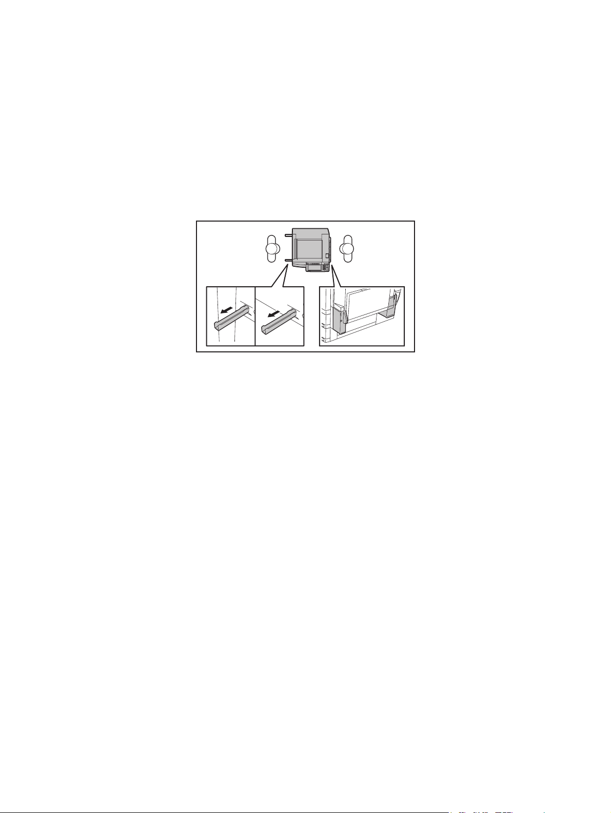
1) Transportation/Installation
- When transporting/installing the equipment, employ two persons and be sure to hold the posi-
tions as shown in the figure.
The equipment is quite heavy and weighs approximately 75 kg (165.34 lb.) therefore pay full
attention when handling it.
- Be sure not to hold the movable parts or units (e.g. the control panel, ADU or RADF) when trans-
porting the equipment.
- Be sure to use a dedicated outlet with AC 110 V / 13.2 A, 115 V or 127 V / 12 A, 220-240 V or 240
V / 8 A for its power source.
- The equipment must be grounded for safety.
- Select a suitable place for installation. Avoid excessive heat, high humidity, dust, vibration and
direct sunlight.
- Provide proper ventilation since the equipment emits a slight amount of ozone.
- To insure adequate working space for the copying operation, keep a minimum clearance of 80
cm (32”) on the left, 80 cm (32”) on the right and 10 cm (4”) on the rear.
- The equipment shall be installed near the socket outlet and shall be accessible.
- Be sure to fix and plug in the power cable securely after the installation so that no one trips over
it.
07/11

2) General Precautions at Service
- Be sure to turn the power OFF and unplug the power cable during service (except for the service
should be done with the power turned ON).
- Unplug the power cable and clean the area around the prongs of the plug and socket outlet once
a year or more. A fire may occur when dust lies on this area.
- When the parts are disassembled, reassembly is the reverse of disassembly unless otherwise
noted in this manual or other related documents. Be careful not to install small parts such as
screws, washers, pins, E-rings, star washers in the wrong places.
- Basically, the equipment should not be operated with any parts removed or disassembled.
- The PC board must be stored in an anti-electrostatic bag and handled carefully using a wristband
since the ICs on it may be damaged due to static electricity.
Caution: Before using the wristband, unplug the power cable of the equipment and
make sure that there are no charged objects which are not insulated in the
vicinity.
- Avoid expose to laser beam during service. This equipment uses a laser diode. Be sure not to
expose your eyes to the laser beam. Do not insert reflecting parts or tools such as a screwdriver
on the laser beam path. Remove all reflecting metals such as watches, rings, etc. before starting
service.
- Be sure not to touch high-temperature sections such as the exposure lamp, fuser unit, damp
heater and areas around them.
- Be sure not to touch high-voltage sections such as the chargers, developer, high-voltage trans-
former, exposure lamp control inverter, inverter for the LCD backlight and power supply unit.
Especially, the board of these components should not be touched since the electric charge may
remain in the capacitors, etc. on them even after the power is turned OFF.
- Make sure that the equipment will not operate before touching potentially dangerous places (e.g.
rotating/operating sections such as gears, belts pulleys, fans and laser beam exit of the laser
optical unit).
- Be careful when removing the covers since there might be the parts with very sharp edges
underneath.
- When servicing the equipment with the power turned ON, be sure not to touch live sections and
rotating/operating sections. Avoid exposing your eyes to laser beam.
- Use designated jigs and tools.
- Use recommended measuring instruments or equivalents.
- Return the equipment to the original state and check the operation when the service is finished.
- Be very careful to treat the touch panel gently and never hit it. Breaking the surface could cause
malfunctions.
3) Important Service Parts for Safety
- The breaker, door switch, fuse, thermostat, thermofuse, thermistor, IC-RAMs including lithium
batteries, etc. are particularly important for safety. Be sure to handle/install them properly. If
these parts are short-circuited and their functions become ineffective, they may result in fatal
accidents such as burnout. Do not allow a short-circuit or do not use the parts not recommended
by Toshiba TEC Corporation.
4) Cautionary Labels
- During servicing, be sure to check the rating plate and cautionary labels such as “Unplug the
power cable during service”, “CAUTION. HOT”, “CAUTION. HIGH VOLTAGE”, “CAUTION.
LASER BEAM”, etc. to see if there is any dirt on their surface and if they are properly stuck to the
equipment.
06/09

5) Disposal of the Equipment, Supplies, Packing Materials, Used Batteries and IC-RAMs
- Regarding the recovery and disposal of the equipment, supplies, packing materials, used batter-
ies and IC-RAMs including lithium batteries, follow the relevant local regulations or rules.
Caution:
Dispose of used batteries and IC-RAMs including lithium batteries according to this manual.
Attention:
Se débarrasser de batteries et IC-RAMs usés y compris les batteries en lithium selon ce manuel.
Vorsicht:
Entsorgung der gebrauchten Batterien und IC-RAMs (inclusive der Lithium-Batterie) nach diesem Handbuch.
05/11


CONTENTS
e-STUDIO200L/230/280
1. SPECIFICATIONS / ACCESSORIES / OPTIONS / SUPPLIES ................................... 1-1
1.1 Specifications....................................................................................................................... 1-1
1.2 Accessories ......................................................................................................................... 1-6
1.3 Options ................................................................................................................................ 1-7
1.3.1 e-STUDIO200L/230/230L/280/280S ........................................................................ 1-7
1.3.2 e-STUDIO202L/203L/232/232S/233/282/282S/283/283S ....................................... 1-8
1.4 Supplies............................................................................................................................. 1-10
1.4.1 e-STUDIO200L/230/230L/280/280S ...................................................................... 1-10
1.4.2 e-STUDIO202L/232/232S/282/282S ...................................................................... 1-10
1.4.3 e-STUDIO203L/233/283/283S ............................................................................... 1-10
1.5 System List ........................................................................................................................ 1-11
1.5.1 e-STUDIO200L/230/230L/280/280S ...................................................................... 1-11
1.5.2 e-STUDIO202L/203L/232/232S/233/282/282S/283/283S ..................................... 1-17
2. OUTLINE OF THE MACHINE ....................................................................................... 2-1
2.1 Sectional View ..................................................................................................................... 2-1
2.2 Electric Parts Layout............................................................................................................ 2-4
2.3 Symbols and Functions of Various Components............................................................... 2-17
2.4 General Description........................................................................................................... 2-26
2.4.1 System block diagram ............................................................................................ 2-26
2.4.2 Construction of boards ........................................................................................... 2-28
2.5 Installation and Replacement of Covers and PC Boards................................................... 2-30
2.5.1 Covers .................................................................................................................... 2-30
2.5.2 PC boards .............................................................................................................. 2-41
2.6 Installation and Replacement of Options ........................................................................... 2-51
3. COPY PROCESS ..........................................................................................................3-1
3.1 General Description of Copying Process............................................................................. 3-1
3.2 Details of Copying Process.................................................................................................. 3-2
3.3 Comparison with e-STUDIO350/450 ................................................................................. 3-13
4. GENERAL OPERATION............................................................................................... 4-1
4.1 Overview of Operation ......................................................................................................... 4-1
4.2 Description of Operation...................................................................................................... 4-2
4.2.1 Warming-up .............................................................................................................. 4-2
4.2.2 Ready state (ready for copying) ............................................................................... 4-2
4.2.3 Drawer feed copying (Upper drawer paper feeding) ................................................ 4-3
4.2.4 Bypass feed copying ................................................................................................ 4-5
4.2.5 Interruption copying .................................................................................................. 4-5
4.3 Detection of Abnormality...................................................................................................... 4-6
4.3.1 Types of abnormality ................................................................................................ 4-6
4.3.2 Description of abnormality ........................................................................................ 4-7
4.4 Flow Chart ......................................................................................................................... 4-12
4.4.1 Immediately after the power is turned ON .............................................................. 4-12
4.4.2 Automatic paper feed copying ................................................................................ 4-14
5. CONTROL PANEL........................................................................................................ 5-1
5.1 Control Panel and Display Panel ......................................................................................... 5-1
5.2 Items Shown on the Control Panel ...................................................................................... 5-2
5.2.1 Display...................................................................................................................... 5-3
5.3 Relation between the Equipment State and Operator’s Operation...................................... 5-8
5.4 Description of Operation.................................................................................................... 5-12
5.4.1 Dot matrix LCD circuit ............................................................................................ 5-12
5.4.2 LED display circuit .................................................................................................. 5-15
© 2004 - 2010 TOSHIBA TEC CORPORATION All rights reserved e-STUDIO200L/202L/203L/230/232/233/280/282/283
1
05/11
CONTENTS

5.5 Disassembly and Replacement ......................................................................................... 5-16
6. SCANNER ..................................................................................................................... 6-1
6.1 Function............................................................................................................................... 6-1
6.2 Construction......................................................................................................................... 6-2
6.3 Description of Operation...................................................................................................... 6-4
6.3.1 Scan motor ............................................................................................................... 6-4
6.3.2 Scanning drive circuit ............................................................................................... 6-5
6.3.3 Initialization at power-ON ......................................................................................... 6-7
6.4 Control of Exposure Lamp................................................................................................... 6-8
6.4.1 General description .................................................................................................. 6-8
6.4.2 Exposure lamp ......................................................................................................... 6-9
6.4.3 Control circuit for the exposure lamp...................................................................... 6-10
6.5 General Description of CCD Control.................................................................................. 6-11
6.5.1 Opto-electronic conversion..................................................................................... 6-11
6.5.2 Shading correction ................................................................................................. 6-11
6.6 Automatic Original Size Detection Circuit .......................................................................... 6-12
6.6.1 Principle of original size detection .......................................................................... 6-12
6.6.2 Process of detection of original size ....................................................................... 6-13
6.7 Disassembly and Replacement ......................................................................................... 6-17
7. IMAGE PROCESSING .................................................................................................. 7-1
7.1 General Description............................................................................................................. 7-1
7.2 Configuration ....................................................................................................................... 7-3
7.3 SLG Board........................................................................................................................... 7-4
7.3.1 Features ...................................................................................................................7-4
7.3.2 Functions of image processing circuit ...................................................................... 7-4
7.4 LGC Board........................................................................................................................... 7-7
7.4.1 Features ...................................................................................................................7-7
7.4.2 Functions of image processing circuit ...................................................................... 7-7
7.5 Laser Driving PC Board.......................................................................................................7-8
8. LASER OPTICAL UNIT ................................................................................................ 8-1
8.1 General Description............................................................................................................. 8-1
8.2 Structure .............................................................................................................................. 8-3
8.3 Laser Diode ......................................................................................................................... 8-6
8.4 Polygonal Motor................................................................................................................... 8-7
8.5 Internal cooling fan-2 ........................................................................................................... 8-8
8.6 Disassembly and Replacement ........................................................................................... 8-9
9. PAPER FEEDING SYSTEM.......................................................................................... 9-1
9.1 Functions ............................................................................................................................. 9-1
9.2 Operation............................................................................................................................. 9-5
9.2.1 Operation of bypass pickup roller ............................................................................. 9-5
9.2.2 Operation of drawer pickup roller ............................................................................. 9-6
9.2.3 Separation of paper .................................................................................................. 9-7
9.2.4 Operation of clutch ................................................................................................... 9-8
9.2.5 General operation..................................................................................................... 9-9
9.3 Drive Circuit of Tray-up Motor............................................................................................ 9-11
9.4 Disassembly and Replacement ......................................................................................... 9-13
10. DRIVE SYSTEM .......................................................................................................... 10-1
10.1 General Description ........................................................................................................... 10-1
10.2 Functions ........................................................................................................................... 10-2
10.3 Main Motor......................................................................................................................... 10-3
10.3.1 Main motor drive..................................................................................................... 10-3
10.3.2 Control signals........................................................................................................ 10-4
10.4 Disassembly and Replacement ......................................................................................... 10-5
e-STUDIO200L/202L/203L/230/232/233/280/282/283 © 2004 - 2010 TOSHIBA TEC CORPORATION All rights reserved
CONTENTS
2

11. DRUM RELATED SECTION....................................................................................... 11-1
11.1 Configuration ..................................................................................................................... 11-1
11.2 Functions ........................................................................................................................... 11-2
11.3 High-Voltage Transformer Output Control Circuit.............................................................. 11-4
11.3.1 General description ................................................................................................ 11-4
11.3.2 Description of Operation......................................................................................... 11-5
11.4 Drum Temperature Detection Circuit ................................................................................. 11-6
11.4.1 General description ................................................................................................ 11-6
11.4.2 Construction ........................................................................................................... 11-6
11.5 Temperature/Humidity Detection Circuit............................................................................ 11-7
11.5.1 General description ................................................................................................ 11-7
11.5.2 Construction .......................................................................................................... 11-7
11.6 Disassembly and Replacement ......................................................................................... 11-8
12. DEVELOPMENT SYSTEM..........................................................................................12-1
12.1 Configuration ..................................................................................................................... 12-1
12.2 Functions ........................................................................................................................... 12-2
12.2.1 General description ................................................................................................ 12-2
12.2.2 Recovered toner supply mechanism ...................................................................... 12-3
12.3 Drive Circuit of Toner Motor............................................................................................... 12-4
12.4 Auto-Toner Circuit.............................................................................................................. 12-6
12.4.1 General description ................................................................................................ 12-6
12.4.2 Function of auto-toner sensor ................................................................................ 12-7
12.5 Disassembly and Replacement ......................................................................................... 12-9
13. FUSER UNIT ...............................................................................................................13-1
13.1 General Description ........................................................................................................... 13-1
13.2 Operation ........................................................................................................................... 13-2
13.3 Functions ........................................................................................................................... 13-3
13.4 Heater Control Circuit ........................................................................................................ 13-5
13.4.1 Configuration .......................................................................................................... 13-5
13.4.2 Temperature detection section............................................................................... 13-6
13.5 Disassembly and Replacement ....................................................................................... 13-11
14. PAPER EXIT SECTION .............................................................................................. 14-1
14.1 General Description ........................................................................................................... 14-1
14.2 Functions ........................................................................................................................... 14-2
14.3 Control Circuit of Exit Motor...............................................................................................14-3
14.4 Exit Motor Drive ................................................................................................................. 14-4
14.5 Disassembly and Replacement ......................................................................................... 14-5
15. AUTOMATIC DUPLEXING UNIT (ADU) (OPTION: MD-0102) .................................. 15-1
15.1 General Description ........................................................................................................... 15-1
15.2 Description of Operations .................................................................................................. 15-2
15.3 Drive of ADU...................................................................................................................... 15-7
15.4 Flow Chart ......................................................................................................................... 15-8
15.5 Disassembly and Replacement ....................................................................................... 15-10
16. POWER SUPPLY UNIT .............................................................................................. 16-1
16.1 Construction....................................................................................................................... 16-1
16.2 Operation of DC Output Circuits ........................................................................................ 16-2
16.3 Output Channel ................................................................................................................. 16-3
16.4 Fuse................................................................................................................................... 16-5
16.5 Configuration of Power Supply Unit................................................................................... 16-6
16.6 Sequence of Power Supply ............................................................................................... 16-7
16.7 AC Wire Harness ............................................................................................................... 16-8
17. PC BOARDS ............................................................................................................... 17-1
© 2004 - 2010 TOSHIBA TEC CORPORATION All rights reserved e-STUDIO200L/202L/203L/230/232/233/280/282/283
3
CONTENTS

e-STUDIO200L/202L/203L/230/232/233/280/282/283 © 2004 - 2010 TOSHIBA TEC CORPORATION All rights reserved
CONTENTS
4
1. SPECIFICATIONS / ACCESSORIES / OPTIONS / SUPPLIES
1.1 Specifications
Values in { } are for e-STUDIO200L/202L/203L and values in [ ] are for e-STUDIO280/280S/282/
282S/283/283S in case that the specification is different among e-STUDIO200L/202L/203L, eSTUDIO230/230L/232/232S/233 and e-STUDIO280/280S/282/282S/283/283S.
Copy process Indirect electrophotographic process (dry)
Type Desktop type (console type: when paper feed pedestal (PFP) and large
capacity feeder (LCF) are installed)
Original table Fixed type (the left rear corner used as guide to place originals)
Accepted originals Sheet, book and 3-dimensional object. The reversing automatic document
feeder (RADF) only accepts paper which are not pasted or stapled. Carbon
paper are not acceptable either.
Maximum size: A3/LD
Single - sided original Double - sided original
MR-3016
MR-3018
50 ~ 127 g/m
35 ~ 157 g/m
2
(13 lb. Bond - 34 lb. Bond) 50 ~ 105 g/m2 (13 lb. Bond - 28 lb. Bond)
2
(9.3 lb. Bond - 58 lb. Cover) 50 ~ 157 g/m2 (13 lb. Bond - 58 lb. Cover)
1
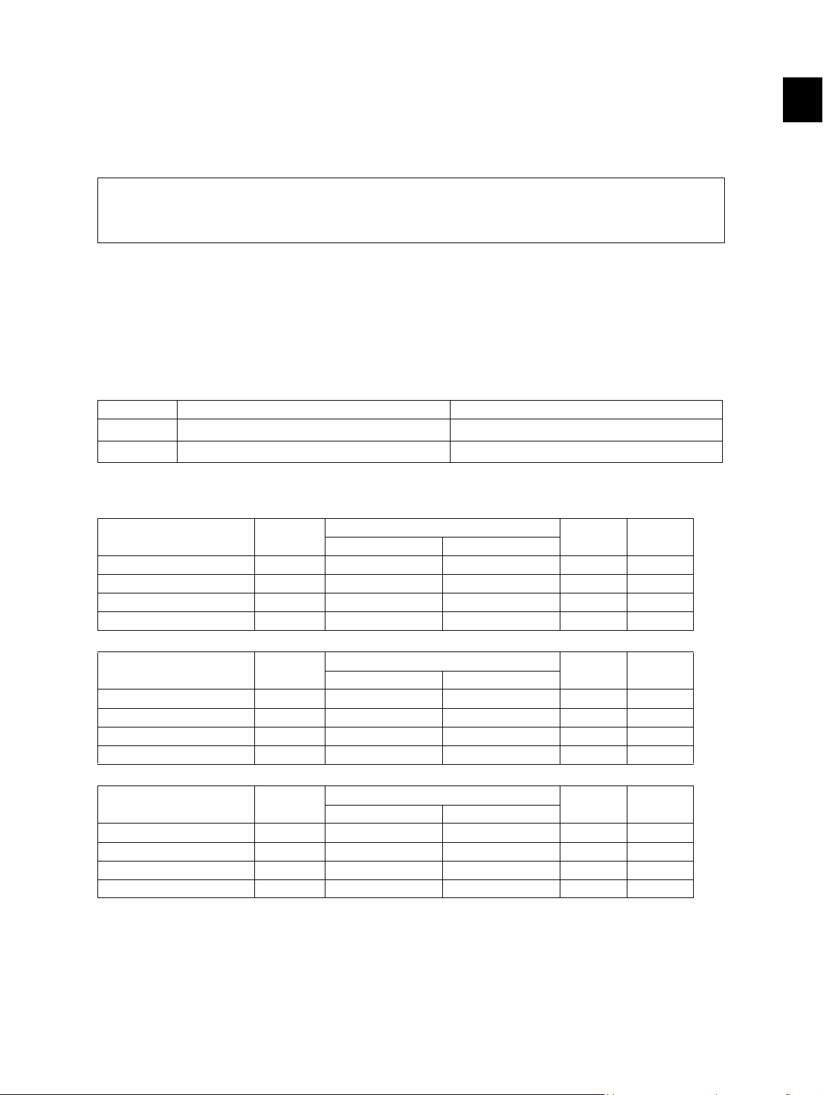
Copy speed (Copies/min.)
e-STUDIO200L/202L/203L
Paper size Drawer
A4, LT, B5, A5-R, ST-R 20 20 16 20 20
A4-R, B5-R, LT-R 19 19 16 19 –
B4, LG 18 18 16 18 –
A3, LD 16 16 16 16 –
Size specified Size not specified
Bypass feed
PFP LCF
e-STUDIO230/230L/232/232S/233
Paper size Drawer
A4, LT, B5, A5-R, ST-R 23 23 16 23 23
A4-R, B5-R, LT-R 21.5 21.5 16 21.5 –
B4, LG 18 18 16 18 –
A3, LD 16 16 16 16 –
Size specified Size not specified
Bypass feed
PFP LCF
e-STUDIO280/280S/282/282S/283/283S
Paper size Drawer
A4, LT, B5, A5-R, ST-R 28 28 16 28 28
A4-R, B5-R, LT-R 21.5 21.5 16 21.5 –
B4, LG 18 18 16 18 –
A3, LD 16 16 16 16 –
Size specified Size not specified
Bypass feed
PFP LCF
* “–” means “Not acceptable”.
* The copy speed in the above table are available when originals are manually placed for single side,
multiple copying.
© 2004 - 2010 TOSHIBA TEC CORPORATION All rights reserved e-STUDIO200L/202L/203L/230/232/233/280/282/283
1 - 1
07/11
SPECIFICATIONS / ACCESSORIES / OPTIONS / SUPPLIES
* When the RADF is used, the copy speed of {20}23[28] sheets per minute is only available under the
following conditions:
• Original/Mode: Single side original/A4/LT size. APS/automatic density are not selected.
• Number of sheets: {20}23[28] or more.
• Reproduction ratio: 100%
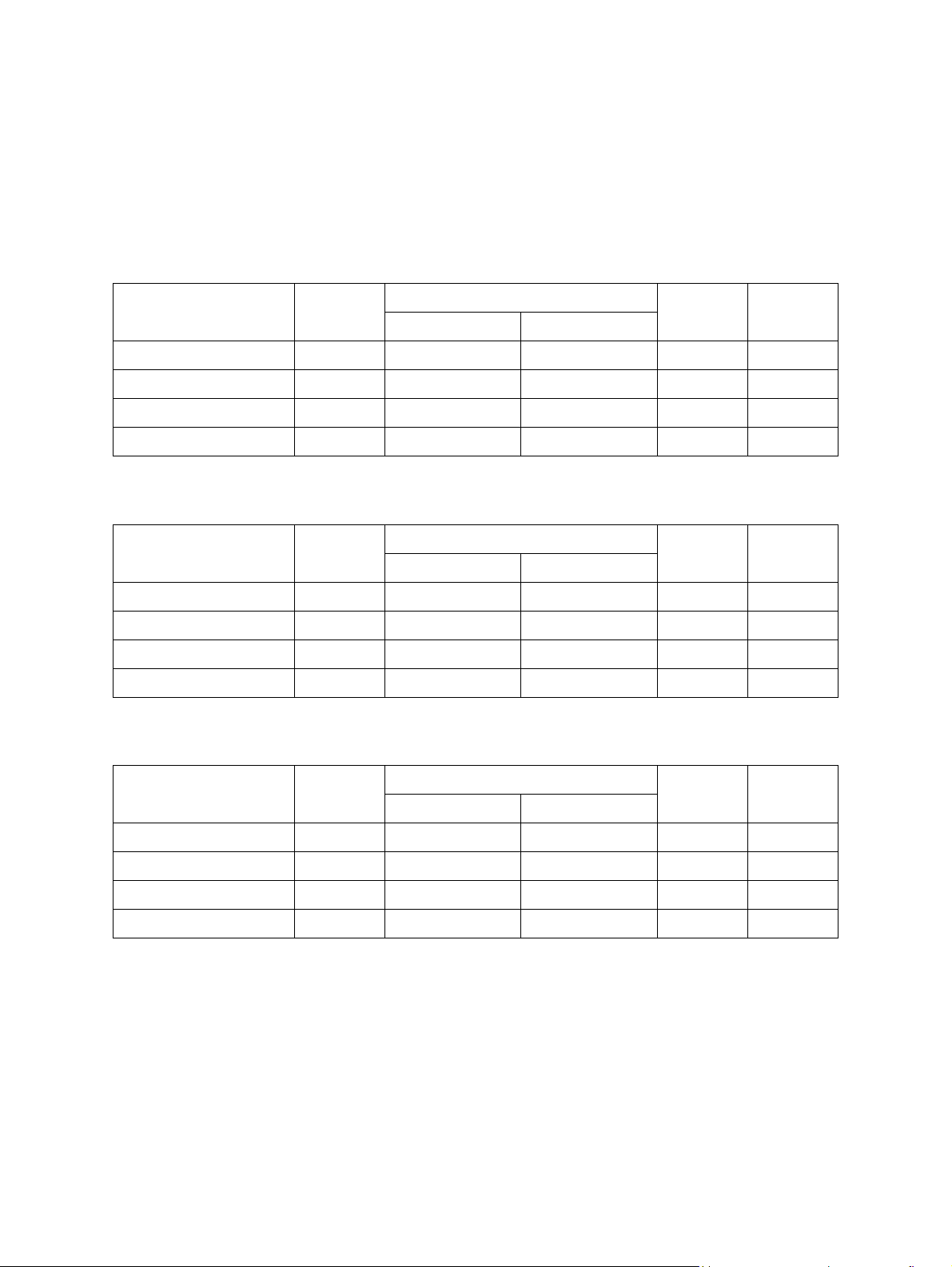
Copy speed for thick paper (Copies/min.)
e-STUDIO200L/202L/203L/230/232/233/280/282/283 series
Thick 1 (81 g/m
Paper size Drawer
A4, LT, B5, A5-R, ST-R {20} 23 [27] {20} 23 [27] {15} 16 [16] {20} 23 [27] {20} 23 [27]
A4-R, B5-R, LT-R {19} 21 [21] {19} 21 [21] {15} 16 [16] {19} 21 [21] {-} - [-]
B4, LG {18} 18 [18] {18} 18 [18] {15} 16 [16] {18} 18 [18] {-} - [-]
A3, LD {15} 16 [16] {15} 16 [16] {15} 16 [16] {15} 16 [16] {-} - [-]
Thick 2 (106 g/m
Paper size Drawer
A4, LT, B5, A5-R, ST-R {-} - [-] {20} 23 [27] {15} 16 [16] {-} - [-] {-} - [-]
A4-R, B5-R, LT-R {-} - [-] {19} 21 [21] {15} 16 [16] {-} - [-] {-} - [-]
B4, LG {-} - [-] {18} 18 [18] {15} 16 [16] {-} - [-] {-} - [-]
A3, LD {-} - [-] {15} 16 [16] {15} 16 [16] {-} - [-] {-} - [-]
2
to 105 g/m2, 21.3 lb. Bond to 28 lb. Bond)
Bypass feed
Size specified Size not specified
2
to 163 g/m2, 28 lb. Bond to 90 lb. Index)
Bypass feed
Size specified Size not specified
PFP LCF
PFP LCF
Thick 3 (164 g/m
Paper size Drawer
A4, LT, B5, A5-R, ST-R {-} - [-] {20} 23 [27] {15} 16 [16] {-} - [-] {-} - [-]
A4-R, B5-R, LT-R {-} - [-] {19} 21 [21] {15} 16 [16] {-} - [-] {-} - [-]
B4, LG {-} - [-] {18} 18 [18] {15} 16 [16] {-} - [-] {-} - [-]
A3, LD {-} - [-] {15} 16 [16] {15} 16 [16] {-} - [-] {-} - [-]
2
to 209 g/m2, 90 lb. Index to 115.7 lb. Index)
Bypass feed
Size specified Size not specified
PFP LCF
* Only A4/LT size is available for the LCF.
* The tolerance is within ±2.
e-STUDIO200L/202L/203L/230/232/233/280/282/283 © 2004 - 2010 TOSHIBA TEC CORPORATION All rights reserved
SPECIFICATIONS / ACCESSORIES / OPTIONS / SUPPLIES
1 - 2
07/11
* System copy speed
Sec.
Copy mode
Single-sided originals
↓
Single-sided copies
Single-sided originals
↓
Double-sided copies
Double-sided originals
↓
Double-sided copies
Double-sided originals
↓
Single-sided copies
1 set
3 sets
5 sets
1 set
3 sets
5 sets
1 set
3 sets
5 sets
1 set
3 sets
5 sets
e-STUDIO200L/
202L/203L
34.18
95.53
154.28
37.44
96.81
155.54
70.26
188.48
306.64
64.65
184.73
302.58
e-STUDIO230/230L/
232/232S/233
31.5
84.8
136.2
34.5
85.9
137.4
64.8
167.7
270.6
57.8
163.1
266.1
e-STUDIO280/280S/
282/282S/283/283S
27.6
72.2
114 .0
31.6
73.4
116 .4
58.9
143.8
228.5
50.5
137.3
222.1
* The system copy speed, including scanning time, is available when 10 sheets of A4/LT size original
are set on RADF and one of the copy modes in the above table is selected. The period of time from
pressing [START] to the paper exit completely out of the equipment based on the actually measured
value.
* Upper drawer is selected and copying is at the non-sort mode.
* Automatic copy density, APS/AMS are turned off.
* Finisher is not installed.
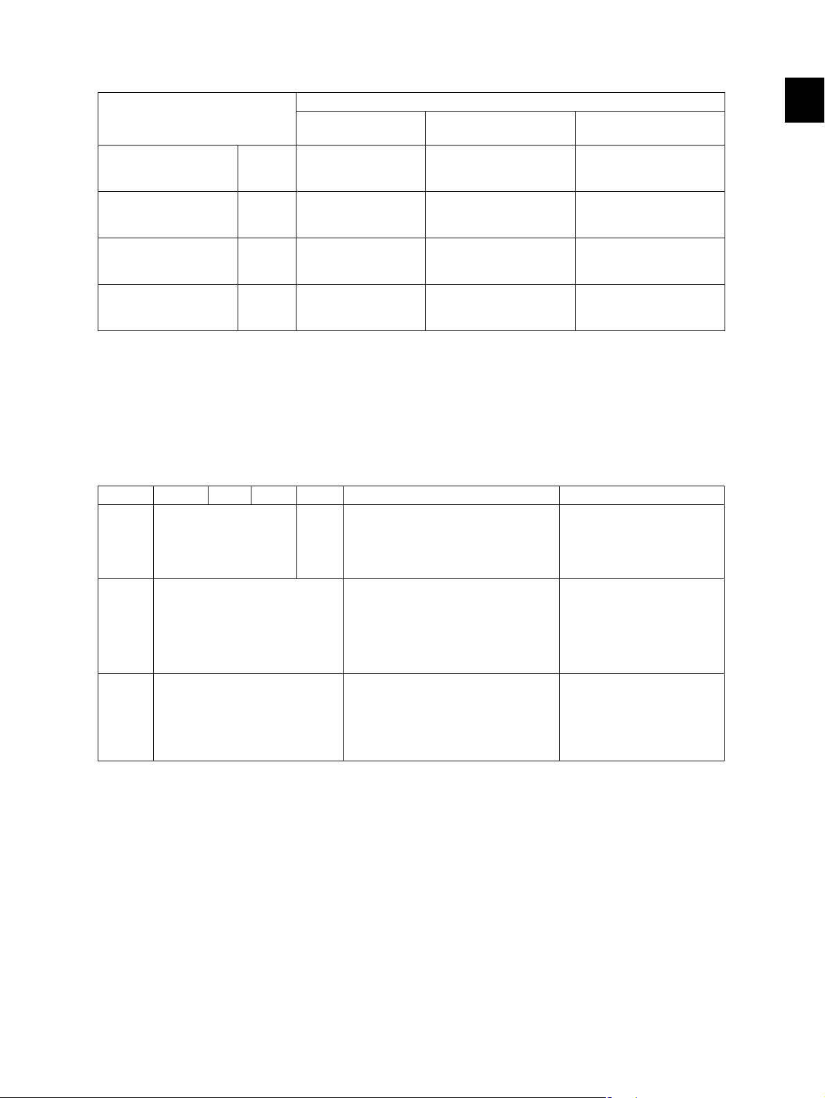
Copy paper
Drawer ADU PFP LCF Bypass copy Remarks
Size A3 to A5-R, LD to ST-R,
FOLIO, COMPUTER,
13"LG, 8.5" x 8.5", 8K,
16K, 16K-R
Weight
Special
paper
64 to 105 g/m
17 to 28 lb. Bond
– Tracing paper, labels,
A4, LT A3 to A5-R, LD to ST-R, FOLIO,
COMPUTER, 13"LG, 8.5" x 8.5", 8K,
16K, 16K-R
(Non-standard or user-specified
sizes can be set.)
2
64 to 209 g/m
Index
(Continuous feeding)
50 to 209 g/m2, 13 lb. Bond to 110 lb.
Index
(Single paper feeding)
OHP film
(thickness: 80 µm or thicker),
tab paper, envelope
(COM10, Monarch, DL, CHO-3,
YOU-4)
2
, 17 lb. Bond to 110 lb.
These special papers recommended by Toshiba Tec
CHO-3: 92 mm x 235 mm
YOU-4: 105 mm x 235 mm
1
First copy time ......................... Approx. 5.4 sec. or less
(A4/LT, upper drawer, 100%, original placed manually)
Warming-up time ..................... Approx. 25 sec. (temperature: 20°C)
Multiple copying....................... Up to 999 copies; Key in set numbers
Reproduction ratio ................... Actual ratio: 100±0.5%
Zooming: 25 to 400% in increments of 1%
(25 to 200% when using RADF)
Resolution/Gradation............... Scanning: 600 dpi x 600 dpi
Printing: Equivalent to 2400 dpi x 600 dpi
Gradation: 256 steps
© 2004 - 2010 TOSHIBA TEC CORPORATION All rights reserved e-STUDIO200L/202L/203L/230/232/233/280/282/283
1 - 3
07/11
SPECIFICATIONS / ACCESSORIES / OPTIONS / SUPPLIES

Eliminated portion.................... Leading edges: 3.0±2.0 mm, Side/trailing edges: 2.0±2.0 mm (copy)
Leading / trailing edges: 5.0±2.0 mm, Side edges: 5.0±2.0 mm (print)
Paper feeding .......................... Standard drawers:
1 or 2 drawers (stack height 60.5 mm, equivalent to 550 sheets;
64 to 80 g/m
2
(17 to 22 lb. Bond)): Depends on destinations or
versions.
PFP:
Option (One drawer or two: stack height 60.5 mm, equivalent to
550 sheets; 64 to 80 g/m
2
(17 to 22 lb. Bond))
LCF:
Option (Stack height 137.5 mm x 2: equivalent to 2500 sheets;
64 to 80 g/m
2
(17 to 22 lb. Bond))
Bypass feeding:
Stack height 11 mm: equivalent to 100 sheets; 64 to 80 g/m
2
(17
to 22 lb. Bond)
Capacity of originals in the reversing automatic document feeder (Option)
.................................................. A3 to A5-R, LD to ST-R:
100 sheets / 80 g/m
2
(Stack height 16 mm or less)
Automatic duplexing unit (ADU is available as standard equipment for some destinations or versions.)
.................................................. Stackless, Switchback type
Toner supply ............................ Automatic toner density detection/supply
Toner cartridge replacing method (There is a recovered toner supply
mechanism.)
Density control......................... Automatic density mode and manual density mode selectable in 11
steps
Weight ..................................... Approximately 75 kg (165.34 lb.): e-STUDIO200L/230/230L/280/280S
Approximately 77 kg (169.75 lb.): e-STUDIO202L/203L/232/232S/233/
282/282S/283 (include the developer material and drum) (The ADU
and Drawer module are installed.)
Power requirements ................ AC 110 V / 13.2 A, 115 V or 127 V / 12 A
220-240 V or 240 V / 8 A (50/60 Hz)
* The acceptable value of each voltage is ±10%.
Power consumption................. 1.5 kW or less (115 V series, 200 V series)
* The electric power is supplied to the RADF, (ADU), Finisher, Job Separator, Offset Tray, PFP and
LCF through the equipment.
Total counter ............................ Electronical counter
e-STUDIO200L/202L/203L/230/232/233/280/282/283 © 2004 - 2010 TOSHIBA TEC CORPORATION All rights reserved
SPECIFICATIONS / ACCESSORIES / OPTIONS / SUPPLIES
1 - 4
07/11
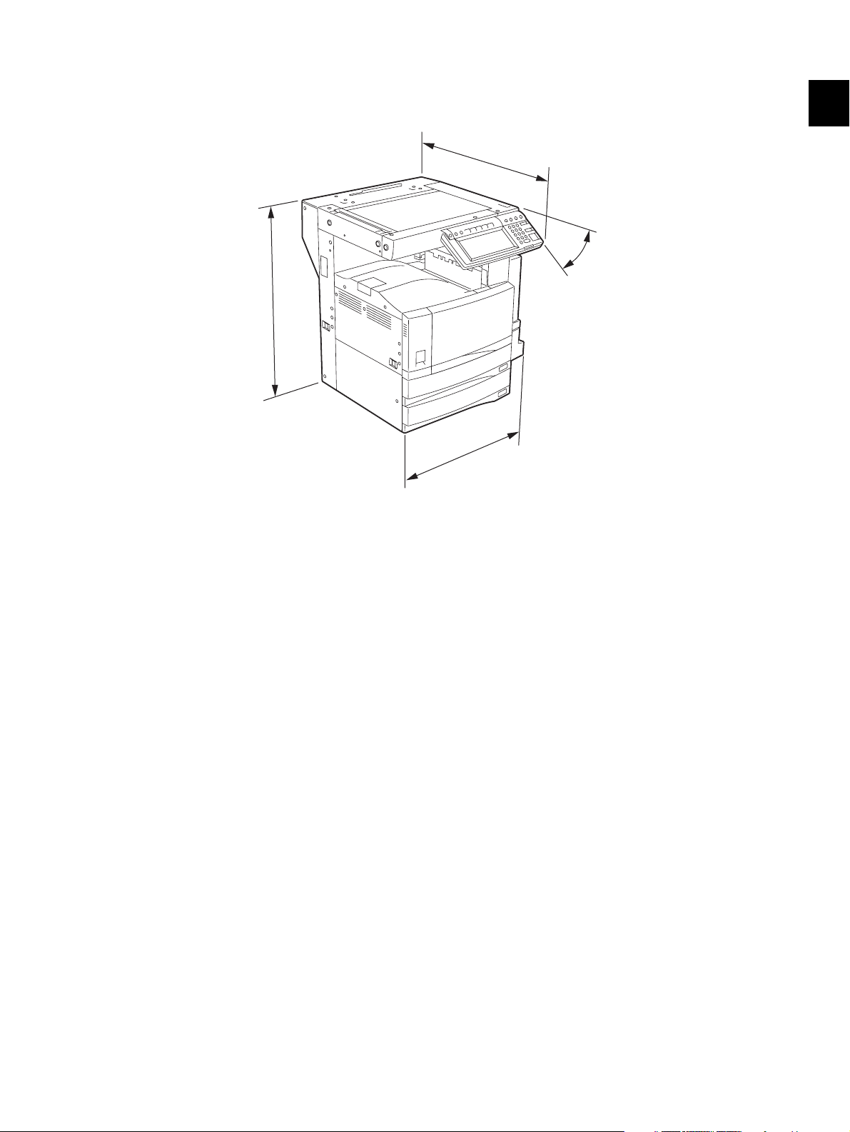
Dimensions of the equipment...................... See the figure below (W 637 x D 719 x H 739 (mm))
* When the tilt angle of the control panel is 45 degrees.
719
45°
739
637
1
Fig. 1-1
© 2004 - 2010 TOSHIBA TEC CORPORATION All rights reserved e-STUDIO200L/202L/203L/230/232/233/280/282/283
1 - 5
04/09
SPECIFICATIONS / ACCESSORIES / OPTIONS / SUPPLIES

1.2 Accessories
Unpacking/setup instruction 1 set
Operator’s manual 3 pcs. (except for MJD)
Operator's manual pocket 1 pc.
Power cable 1 pc.
Warranty sheet 1 pc. (for NAD)
Setup report 1 set (for NAD and MJD)
Customer satisfaction card 1 pc. (for MJD)
Drum (installed inside of the equipment) 1 pc.
Toner cartridge 1 pc. (except for NAD, MJD)
Developer material 1 pc. (except for NAD, MJD)
Control panel stopper 1 pc.
Blind seal 1 pc.
Rubber plug 5 pcs.
CD-ROM
Transfer charger wire cleaner
(installed inside of the transfer cover)
Paper stopper
Stopper bracket
*1
*1
4 pcs.
1 pc.
1 pc.
1 pc.
*2
Machine version
NAD: North America
ARD: Argentina
ASD: Central and South America / Hong Kong
AUD: Australia
MJD: Europe
ASU: Asia
SAD: Saudi Arabia
IRD: Iran
CND: China
TWD: Taiwan
JPD: Japan
KRD: Korea
*1: e-STUDIO200L/230/230L/280/280S only
*2: In e-STUDIO202L/203L/232/232S/233/282/282S/283, 2 discs are included.
e-STUDIO200L/202L/203L/230/232/233/280/282/283 © 2004 - 2010 TOSHIBA TEC CORPORATION All rights reserved
SPECIFICATIONS / ACCESSORIES / OPTIONS / SUPPLIES
1 - 6
07/11

1.3 Options
1.3.1 e-STUDIO200L/230/230L/280/280S
Platen Cover KA-3511 PC/PC-C
Reversing Automatic Document Feeder (RADF) MR-3016
Drawer Module MY-1021/-C
Paper Feed Pedestal (PFP) KD-1011/-C
Large Capacity Feeder (LCF) KD-1012 A4/LT/A4-C
Finisher (Hanging type) MJ-1022/-C
Saddle stitch Finisher MJ-1025/-C
Hole Punch Unit
MJ-6005 N/E/F/S
Staple Cartridge STAPLE-1600 (for MJ-1022)
STAPLE-2000 (for MJ-1025)
Bridge Kit KN-3520/-C
Job Separator MJ-5004/-C
Offset Tray MJ-5005/-C
Key copy Counter, Key copy counter socket MU-8, MU-10
Work Tray KK-3511
Damp Heater MF-2320 U/E
Fax Board GD-1150 NA/AU/EU/TW/C/AS
2nd Line for Fax Board GD-1160 NA/EU/TW/C
Wireless LAN Adapter GN-1010
PCI Slot GO-1040/C
Scrambler Board GP-1030
Printer Kit GM-1020/GM-1030
Printer/Scanner Kit GM-2020/GM-2030
Scanner upgrade Kit GM-3020/GM-3030
Parallel interface kit GF-1140
Desk MH-1700
Harness kit for coin controller GQ-1020
Automatic Duplexing Unit (ADU) MD-0102
Slot cover KE-2330
NIC board GF-1150
Data overwrite kit GP-1050
*1
1
* 1) N: North America E: Europe F: France S: Sweden
Notes:
• The bridge unit (KN-3520) is necessary for installation of the finisher (MJ-1022, MJ-1025).
• The finisher (MJ-1025) is necessary for installation of the hole punch unit (MJ-6005N/E/F/S).
• The PCI slot (GO-1040) is necessary for installation of the scrambler board (GP-1030) and
parallel interface kit (GF-1140).
• GM-1030/GM-2030/GM-3030 are exclusive for e-STUDIO200L.
They do not operate with e-STUDIO230/230L/280/280S.
© 2004 - 2010 TOSHIBA TEC CORPORATION All rights reserved e-STUDIO200L/202L/203L/230/232/233/280/282/283
1 - 7
05/11
SPECIFICATIONS / ACCESSORIES / OPTIONS / SUPPLIES

1.3.2 e-STUDIO202L/203L/232/232S/233/282/282S/283/283S
Platen Cover KA-3511PC/-C
Reversing Automatic Document Feeder (RADF) MR-3020
Automatic Duplexing Unit (ADU) MD-0102
Drawer module MY-1021/-C
Slot cover KE-2330
Paper Feed Pedestal (PFP) KD-1011/-C
Large Capacity Feeder (LCF) KD-1012LT/A4/A4-C
Finisher (Hanging type) MJ-1022/-C
Finisher (Console saddle stitcher type) MJ-1025
Hole punch unit (for MJ-1025)
MJ-6005N/E/F/S
Staple cartridge STAPLE-1600 (for MJ-1022)
STAPLE-2000 (for MJ-1025)
Bridge kit KN-3520/-C
Job separator MJ-5004/-C
Offset tray MJ-5005/-C
Work tray KK-3511/-C
Damp heater MF-2320U/E
Fax board GD-1150NA/EU/AU/AS/C/TW
GD-1151NA/EU/AU/AS/C/TW
2nd line for fax board GD-1160NA/EU-N/C/TW
GD-1260NA/EU/C/TW
Printer kit GM-1070/1071/1080U/1081U
Printer/Scanner kit GM-2070/2071/2080U/2081U
Scanner kit GM-4070/GM-4080U
Printer ELK GM-1130 (e-STUDIO232/232S/233/282/282S/
283/283S)
GM-1140U (e-STUDIO202L/203L)
Printer/Scanner ELK GM-2130 (e-STUDIO232/232S/233/282/282S/
283/283S)
GM-2140U (e-STUDIO202L/203L)
Scanner ELK GM-4130 (e-STUDIO232/232S/233/282/282S/
283/283S)
GM-4140U (e-STUDIO202L/203L)
Memory GC-1230
Scrambler board GP-1040
Wireless LAN module GN-1041
Bluetooth module GN-2010
Antenna GN-3010
Data overwrite kit GP-1060
PCI slot GO-1060
e-BRIDGE ID Gate (HID iClass) KP-2004
e-BRIDGE ID Gate (MIFARE) KP-2005
Desk MH-1700
Harness kit for coin controller GQ-1020
*1
* 1) N: North America E: Europe F: France S: Sweden
e-STUDIO200L/202L/203L/230/232/233/280/282/283 © 2004 - 2010 TOSHIBA TEC CORPORATION All rights reserved
SPECIFICATIONS / ACCESSORIES / OPTIONS / SUPPLIES
1 - 8
10/01

Notes:
• The bridge kit (KN-3520) is necessary for installation of the finisher (MJ-1022 or MJ-1025).
• The saddle stitch finisher (MJ-1025) is necessary for installation of the hole punch unit
(MJ-6005N/E/F/S).
• The PCI slot (GO-1060) is necessary for installation of the scrambler board (GP-1040).
• The antenna (GN-3010) is necessary to enable the wireless LAN module (GN-1041) and
Bluetooth module (GN-2010).
• When the wireless LAN module (GN-1041) and the Bluetooth module (GN-2010) are
installed, only 1 antenna (GN-3010) can be connected to each.
• GM-1080U / GM-2080U / GM-4080U are exclusive to e-STUDIO202L. They do not operate
with e-STUDIO232/232S/282/282S.
• GM-1081U / GM-2081U / GM-4080U are exclusive to e-STUDIO202L/203L. They do not
operate with e-STUDIO232/232S/233/282/282S/283.
• The Printer kit (GM-1070/1080U) or Printer/Scanner kit (GM-2070/2080U) does not have a
function for printing an XPS file.
• To enable an XPS file to be printed by the Printer kit (GM-1071/1081U) or Printer/Scanner kit
(GM-2071/1081U), the Memory (GC-1230) is required to be installed.
• To enable an XPS file to be printed by the Printer ELK (GM-1130/1140U) or Printer/Scanner
ELK (GM-2130/2140U), the Memory (GC-1230) is required to be installed.
1
© 2004 - 2010 TOSHIBA TEC CORPORATION All rights reserved e-STUDIO200L/202L/203L/230/232/233/280/282/283
1 - 9
10/01
SPECIFICATIONS / ACCESSORIES / OPTIONS / SUPPLIES
1.4 Supplies
1.4.1 e-STUDIO200L/230/230L/280/280S
Drum OD-1600
Toner cartridge
Developer D-2320 /C
PS-ZT2320 /T/D/C/E
* 1) T: Taiwan D: Asia C: China E: Europe NONE: North America
1.4.2 e-STUDIO202L/232/232S/282/282S
Drum OD-1600
Toner cartridge
Developer D-2340 /C
PS-ZT2340 /T/D/C/E
* 1) T: Taiwan D: Asia C: China E: Europe NONE: North America
1.4.3 e-STUDIO203L/233/283/283S
*1
*1
Drum OD-1600
Toner cartridge
Developer D-2340 /C
PS-ZT2840 /E
PS-ZT2340C
*1
*1
* 1) C: China E: Europe NONE: North America
e-STUDIO200L/202L/203L/230/232/233/280/282/283 © 2004 - 2010 TOSHIBA TEC CORPORATION All rights reserved
SPECIFICATIONS / ACCESSORIES / OPTIONS / SUPPLIES
1 - 10
07/11
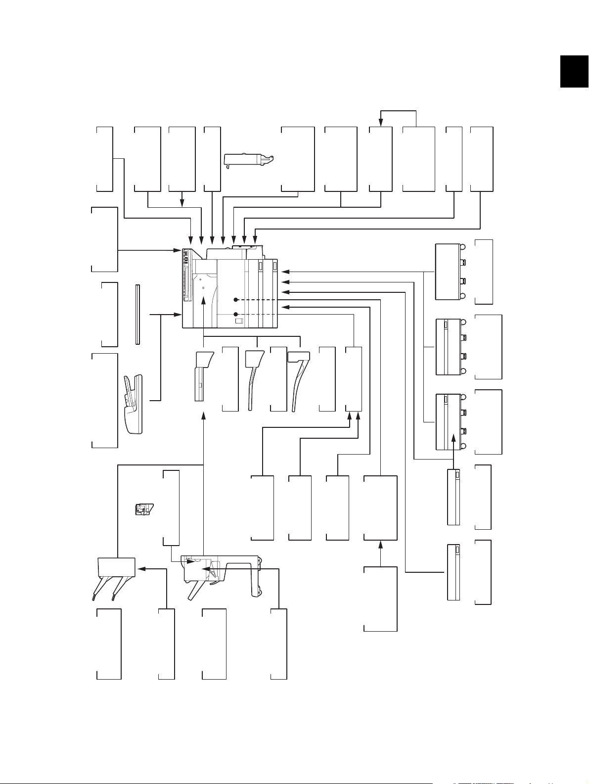
1.5 System List
1.5.1 e-STUDIO200L/230/230L/280/280S
)
KK-3511
Work Tray
GQ-1020
coin controller
Harness kit for
KA-3511
Platen Cover
MU-8
Counter
Key Copy
MU-10
Key Copy
Counter Socket
MF-2320 U/E
Damp Heater
ADU
(
MD-0102
Automatic
Duplexing Unit
Printer/
GM-2020/
Scanner Kit
GM-2030
Printer Kit
Scanner
GM-1030
GM-1020/
GM-3030
GM-3020/
Upgrade Kit
Data
GF-1150
NIC board
GP-1050
overwrite kit
Desk
MH-1700
1
)
RADF
(
MR-3016
Reversing Automatic
Document Feeder
)
Hole Punch Unit
MJ-6005 N/E/F/S
KN-3520
Bridge Kit
MJ-5004
Job Separator
kit
Parallel interface
GF-1140
Scrambler
Board
MJ-5005
Offset Tray
GP-1030
Wireless LAN
PCI Slot
Adapter
GN-1010
GO-1040
GD-1150
FAX Board
FAX Board
2nd Line for
TW/C/AS
NA/AU/EU/
GD-1160
NA/EU/TW/C
Feeder (LCF)
Large Capacity
KD-1012 A4/LT
KD-1011
Paper Feed
Pedestal (PFP)
MY-1021
Drawer Module
KE-2330
Slot cover
Finisher
MJ-1022
Hanging type
(
STAPLE-1600
Staple Cartridge
Finisher
MJ-1025
Saddle stitch
STAPLE-2000
Staple Cartridge
Fig. 1-2
© 2004 - 2010 TOSHIBA TEC CORPORATION All rights reserved e-STUDIO200L/202L/203L/230/232/233/280/282/283
SPECIFICATIONS / ACCESSORIES / OPTIONS / SUPPLIES
1 - 11
05/11

e-STUDIO280/280S
Central and
Area North America
Machine version
(destination)
NAD
(115V)
Model name e-STUDIO280 e-STUDIO280 e-STUDIO280 e-STUDIO280 e-STUDIO280
Platen cover KA-3511PC KA-3511PC KA-3511PC KA-3511PC KA-3511PC
RADF MR-3016 MR-3016 MR-3016 MR-3016 MR-3016
Drawer module
(for Equipment)
Drawer module
(for PFP)
Standard MY-1021 Standard Standard MY-1021
MY-1021 MY-1021 MY-1021 MY-1021 MY-1021
Slot cover - Standard - - KE-2330
ADU Standard MD-0102 Standard Standard MD-0102
PFP KD-1011 KD-1011 KD-1011 KD-1011 KD-1011
LCF KD-1012LT KD-1012A4 KD-1012A4 KD-1012A4 KD-1012A4
Finisher
(Hanging type)
Staple cartridge
(for MJ-1022)
MJ-1022 MJ-1022 MJ-1022 MJ-1022 MJ-1022
STAPLE-1600 STAPLE-1600 STAPLE-1600 STAPLE-1600 STAPLE-1600
Saddle stitch finisher MJ-1025 MJ-1025 MJ-1025 MJ-1025 MJ-1025
Staple cartridge
(for MJ-1025)
STAPLE-2000 STAPLE-2000 STAPLE-2000 STAPLE-2000 STAPLE-2000
Hole punch unit MJ-6005N MJ-6005E MJ-6005E MJ-6005E/F/S MJ-6005E
Bridge kit KN-3520 KN-3520 KN-3520 KN-3520 KN-3520
Job separator MJ-5004 MJ-5004 MJ-5004 MJ-5004 MJ-5004
Offset tray MJ-5005 MJ-5005 MJ-5005 MJ-5005 MJ-5005
Key copy counter MU-8 MU-8 MU-8 MU-8 MU-8
Key copy counter
socket
MU-10 MU-10 MU-10 MU-10 MU-10
Work tray KK-3511 KK-3511 KK-3511 KK-3511 KK-3511
Damp heater MF-2320U Standard Standard MF-2320E Standard
Fax board GD-1150NA GD-1150AS GD-1150AU GD-1150EU GD-1150AS
2nd line for Fax
board
Wireless LAN
adapter
GD-1160NA GD-1160EU GD-1160EU GD-1160EU GD-1160EU
GN-1010 GN-1010 GN-1010 GN-1010 GN-1010
PCI slot GO-1040 GO-1040 GO-1040 GO-1040 GO-1040
Scrambler board GP-1030 GP-1030 GP-1030 GP-1030 GP-1030
Parallel interface kit GF-1140 GF-1140 GF-1140 GF-1140 GF-1140
NIC board Standard GF-1150 Standard Standard GF-1150
Printer/Scanner kit GM-2020 GM-2020 GM-2020 GM-2020 GM-2020
Printer kit GM-1020 GM-1020 GM-1020 GM-1020 GM-1020
Scanner upgrade kit GM-3020 GM-3020 GM-3020 GM-3020 GM-3020
Desk MH-1700 MH-1700 MH-1700 MH-1700 MH-1700
Harness kit for coin
controller
GQ-1020 GQ-1020 GQ-1020 GQ-1020 GQ-1020
South America/
Hong Kong
ASD
(220-240V)
Australia Europe Asia
AUD
(220-240V)
MJD
(220-240V)
ASU
(220-240V)
e-STUDIO200L/202L/203L/230/232/233/280/282/283 © 2004 - 2010 TOSHIBA TEC CORPORATION All rights reserved
SPECIFICATIONS / ACCESSORIES / OPTIONS / SUPPLIES
1 - 12
04/09

Area Saudi Arabia Iran China Taiwan
Machine version
(destination)
SAD
(127V)
IRD
(220-240V)
CND
(220-240V)
TWD
(110V)
Model name e-STUDIO280 e-STUDIO280 e-STUDIO280S e-STUDIO280 e-STUDIO280
Platen cover KA-3511PC KA-3511PC Standard Standard KA-3511PC
RADF MR-3016 MR-3016 MR-3016 MR-3016 MR-3016
Drawer module
(for Equipment)
Drawer module
(for PFP)
MY-1021 Standard Standard Standard Standard
MY-1021 MY-1021 MY-1021 MY-1021 MY-1021
Slot cover KE-2330 - - - -
ADU MD-0102 Standard MD-0102 Standard MD-0102
PFP KD-1011 KD-1011 KD-1011 KD-1011 KD-1011
LCF KD-1012A4 KD-1012A4 KD-1012-C KD-1012-C KD-1012A4
Finisher
(Hanging type)
Staple cartridge
(for MJ-1022)
MJ-1022 MJ-1022 MJ-1022-C MJ-1022-C MJ-1022
STAPLE-1600 STAPLE-1600 STAPLE-1600 STAPLE-1600 STAPLE-1600
Saddle stitch finisher MJ-1025 MJ-1025 MJ-1025 MJ-1025 MJ-1025
Staple cartridge
(for MJ-1025)
STAPLE-2000 STAPLE-2000 STAPLE-2000 STAPLE-2000 STAPLE-2000
Hole punch unit MJ-6005E MJ-6005E MJ-6005E MJ-6005E MJ-6005E
Bridge kit KN-3520 KN-3520 KN-3520-C KN-3520-C KN-3520
Job separator MJ-5004 MJ-5004 MJ-5004-C MJ-5004-C MJ-5004
Offset tray MJ-5005 MJ-5005 MJ-5005-C MJ-5005-C MJ-5005
Key copy counter MU-8 MU-8 MU-8 MU-8 MU-8
Key copy counter
socket
MU-10 MU-10 MU-10 MU-10 MU-10
Work tray KK-3511 KK-3511 KK-3511 KK-3511 KK-3511
Damp heater Standard Standard Standard Standard Standard
Fax board GD-1150NA N/A GD-1150C GD-1150C GD-1150TW
2nd line for Fax
board
Wireless LAN
adapter
GD-1160NA N/A GD-1160C GD-1160C GD-1160TW
GN-1010 GN-1010 GN-1010 GN-1010 GN-1010
PCI slot GO-1040 GO-1040 GO-1040C GO-1040C GO-1040
Scrambler board GP-1030 GP-1030 GP-1030 GP-1030 GP-1030
Parallel interface kit GF-1140 GF-1140 GF-1140 GF-1140 GF-1140
NIC board GF-1150 Standard GF-1150 Standard Standard
Printer/Scanner kit GM-2020 Standard GM-2020 Standard GM-2020
Printer kit GM-1020 GM-1020 GM-1020 GM-1020 GM-1020
Scanner upgrade kit GM-3020 GM-3020 GM-3020 GM-3020 GM-3020
Desk MH-1700 MH-1700 MH-1700 MH-1700 MH-1700
Harness kit for coin
controller
GQ-1020 GQ-1020 GQ-1020 GQ-1020 GQ-1020
1
© 2004 - 2010 TOSHIBA TEC CORPORATION All rights reserved e-STUDIO200L/202L/203L/230/232/233/280/282/283
1 - 13
04/09
SPECIFICATIONS / ACCESSORIES / OPTIONS / SUPPLIES

e-STUDIO230/230L
Central and
Area North America
Machine version
(destination)
NAD
(115V)
Model name e-STUDIO230 e-STUDIO230 e-STUDIO230 e-STUDIO230 e-STUDIO230L
Platen cover KA-3511PC KA-3511PC KA-3511PC KA-3511PC KA-3511PC
RADF MR-3016 MR-3016 MR-3016 MR-3016 MR-3016
Drawer module
(for Equipment)
Drawer module
(for PFP)
Standard MY-1021 Standard Standard MY-1021
MY-1021 MY-1021 MY-1021 MY-1021 MY-1021
Slot cover - Standard - - Standard
ADU Standard MD-0102 Standard Standard MD-0102
PFP KD-1011 KD-1011 KD-1011 KD-1011 KD-1011
LCF KD-1012LT KD-1012A4 KD-1012A4 KD-1012A4 KD-1012A4
Finisher
(Hanging type)
Staple cartridge
(for MJ-1022)
MJ-1022 MJ-1022 MJ-1022 MJ-1022 MJ-1022
STAPLE-1600 STAPLE-1600 STAPLE-1600 STAPLE-1600 STAPLE-1600
Saddle stitch finisher MJ-1025 MJ-1025 MJ-1025 MJ-1025 MJ-1025
Staple cartridge
(for MJ-1025)
STAPLE-2000 STAPLE-2000 STAPLE-2000 STAPLE-2000 STAPLE-2000
Hole punch unit MJ-6005N MJ-6005E MJ-6005E MJ-6005E/F/S MJ-6005E
Bridge kit KN-3520 KN-3520E KN-3520 KN-3520 KN-3520
Job separator MJ-5004 MJ-5004 MJ-5004 MJ-5004 MJ-5004
Offset tray MJ-5005 MJ-5005 MJ-5005 MJ-5005 MJ-5005
Key copy counter MU-8 MU-8 MU-8 MU-8 MU-8
Key copy counter
socket
MU-10 MU-10 MU-10 MU-10 MU-10
Work tray KK-3511 KK-3511 KK-3511 KK-3511 KK-3511
Damp heater MF-2320U Standard Standard MF-2320E MF-2320E
Fax board GD-1150NA GD-1150AS GD-1150AU GD-1150EU GD-1150EU
2nd line for Fax
board
Wireless LAN
adapter
GD-1160NA GD-1160EU GD-1160EU GD-1160EU GD-1160EU
GN-1010 GN-1010 GN-1010 GN-1010 GN-1010
PCI slot GO-1040 GO-1040 GO-1040 GO-1040 GO-1040
Scrambler board GP-1030 GP-1030 GP-1030 GP-1030 GP-1030
Parallel interface kit GF-1140 GF-1140 GF-1140 GF-1140 GF-1140
NIC board Standard GF-1150 Standard Standard GF-1150
Printer/Scanner kit GM-2020 GM-2020 GM-2020 GM-2020 GM-2020
Printer kit GM-1020 GM-1020 GM-1020 GM-1020 GM-1020
Scanner upgrade kit GM-3020 GM-3020 GM-3020 GM-3020 GM-3020
Desk MH-1700 MH-1700 MH-1700 MH-1700 MH-1700
Harness kit for coin
controller
GQ-1020 GQ-1020 GQ-1020 GQ-1020 GQ-1020
South America/
Hong Kong
ASD
(220-240V)
Australia Europe
AUD
(220-240V)
MJD
(220-240V)
e-STUDIO200L/202L/203L/230/232/233/280/282/283 © 2004 - 2010 TOSHIBA TEC CORPORATION All rights reserved
SPECIFICATIONS / ACCESSORIES / OPTIONS / SUPPLIES
1 - 14
04/09

Area Asia Saudi Arabia China Taiwan
Machine version
(destination)
ASU
(220-240V)
SAD
(127V)
CND
(220-240V)
TWD
(110V)
Model name e-STUDIO230 e-STUDIO230 e-STUDIO230 e-STUDIO230
Platen cover KA-3511PC KA-3511PC Standard KA-3511PC
RADF MR-3016 MR-3016 MR-3016 MR-3016
Drawer module
(for Equipment)
Drawer module
(for PFP)
MY-1021 MY-1021 Standard Standard
MY-1021 MY-1021 MY-1021 MY-1021
Slot cover KE-2330 KE-2330 - -
ADU MD-0102 MD-0102 Standard MD-0102
PFP KD-1011 KD-1011 KD-1011 KD-1011
LCF KD-1012A4 KD-1012A4 KD-1012A4 KD-1012A4
Finisher
(Hanging type)
Staple cartridge
(for MJ-1022)
MJ-1022 MJ-1022 MJ-1022-C MJ-1022
STAPLE-1600 STAPLE-1600 STAPLE-1600 STAPLE-1600
Saddle stitch finisher MJ-1025 MJ-1025 MJ-1025 MJ-1025
Staple cartridge
(for MJ-1025)
STAPLE-2000 STAPLE-2000 STAPLE-2000 STAPLE-2000
Hole punch unit MJ-6005E MJ-6005E MJ-6005E MJ-6005E
Bridge kit KN-3520 KN-3520 KN-3520-C KN-3520
Job separator MJ-5004 MJ-5004 MJ-5004-C MJ-5004
Offset tray MJ-5005 MJ-5005 MJ-5005-C MJ-5005
Key copy counter MU-8 MU-8 MU-8 MU-8
Key copy counter
socket
MU-10 MU-10 MU-10 MU-10
Work tray KK-3511 KK-3511 KK-3511 KK-3511
Damp heater Standard Standard Standard Standard
Fax board GD-1150AS GD-1150NA GD-1150C GD-1150TW
2nd line for Fax
board
Wireless LAN
adapter
GD-1160EU GD-1160NA GD-1160C GD-1160TW
GN-1010 GN-1010 GN-1010 GN-1010
PCI slot GO-1040 GO-1040 GO-1040C GO-1040
Scrambler board GP-1030 GP-1030 GP-1030 GP-1030
Parallel interface kit GF-1140 GF-1140 GF-1140 GF-1140
NIC board GF-1150 GF-1150 Standard Standard
Printer/Scanner kit GM-2020 GM-2020 Standard GM-2020
Printer kit GM-1020 GM-1020 GM-1020 GM-1020
Scanner upgrade kit GM-3020 GM-3020 GM-3020 GM-3020
Desk MH-1700 MH-1700 MH-1700 MH-1700
Harness kit for coin
controller
GQ-1020 GQ-1020 GQ-1020 GQ-1020
1
© 2004 - 2010 TOSHIBA TEC CORPORATION All rights reserved e-STUDIO200L/202L/203L/230/232/233/280/282/283
1 - 15
04/09
SPECIFICATIONS / ACCESSORIES / OPTIONS / SUPPLIES

e-STUDIO200L
Area North America
Machine version
(destination)
NAD
(115V)
Model name e-STUDIO200L e-STUDIO200L
Platen cover KA-3511PC KA-3511PC
RADF MR-3016 MR-3016
Drawer module
(for Equipment)
Drawer module
(for PFP)
MY-1021 MY-1021
MY-1021 MY-1021
Slot cover Standard Standard
ADU MD-0102 MD-0102
PFP KD-1011 KD-1011
LCF KD-1012LT KD-1012A4
Finisher
(Hanging type)
Staple cartridge
(for MJ-1022)
MJ-1022 MJ-1022
STAPLE-1600 STAPLE-1600
Saddle stitch finisher MJ-1025 MJ-1025
Staple cartridge
(for MJ-1025)
STAPLE-2000 STAPLE-2000
Hole punch unit MJ-6005N MJ-6005E
Bridge kit KN-3520 KN-3520
Job separator MJ-5004 MJ-5004
Offset tray MJ-5005 MJ-5005
Key copy counter MU-8 MU-8
Key copy counter
socket
MU-10 MU-10
Work tray KK-3511 KK-3511
Damp heater MF-2320 Standard
Fax board GD-1150NA GD-1150AS
2nd line for Fax
board
Wireless LAN
adapter
GD-1160NA GD-1160EU
GN-1010 GN-1010
PCI slot GO-1040 GO-1040
Scrambler board GP-1030 GP-1030
Parallel interface kit GF-1140 GF-1140
NIC board GF-1150 GF-1150
Printer/Scanner kit GM-2030 GM-2030
Printer kit GM-1030 GM-1030
Scanner upgrade kit GM-3030 GM-3030
Desk MH-1700 MH-1700
Harness kit for coin
controller
GQ-1020 GQ-1020
Central and
South America
ASD
(220-240V)
e-STUDIO200L/202L/203L/230/232/233/280/282/283 © 2004 - 2010 TOSHIBA TEC CORPORATION All rights reserved
SPECIFICATIONS / ACCESSORIES / OPTIONS / SUPPLIES
1 - 16
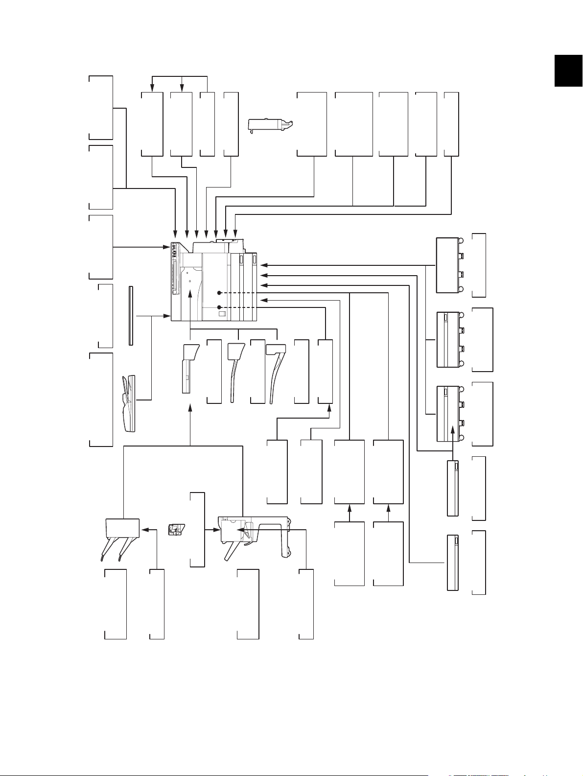
1.5.2 e-STUDIO202L/203L/232/232S/233/282/282S/283/283S
1
ID Gate
KP-2005
e-BRIDGE
ID Gate
KP-2004
e-BRIDGE
GQ-1020
coin controller
Harness kit for
KA-3511
Platen Cover
)
RADF
(
module
GN-1041
Wireless LAN
Bluetooth
module
GN-2010
Antenna
GN-3010
KN-3520
Bridge Kit
MF-2320 U/E
Damp Heater
Job Separator
MJ-5004
)
ADU
(
Automatic
Duplexing Unit
PCI Slot
MJ-5005
Offset Tray
.
Printer/
MD-0102
GO-1060
ELK
GM-2070/2071
Scanner Kit
GM-2130/2140U
GM-2080U/2081U
ELK
.
Printer Kit
GM-1070/1071
GM1130/1140U
GM-1080U/1081U
ELK
.
Memory
Scanner Kit
GM-4070/4080U
GM-4130/4140U
GC-1230
Desk
MH-1700
Feeder (LCF)
Large Capacity
KD-1012 A4/LT
MR-3020
Reversing Automatic
Document Feeder
)
Finisher
MJ-1022
Hanging type
(
Hole Punch Unit
STAPLE-1600
Staple Cartridge
MJ-6005 N/E/F/S
Saddle stitch
Finisher
MJ-1025
Board
GP-1040
Scrambler
Fig. 1-3
kit
GP-1060
Data overwrite
Staple Cartridge
FAX Board
2nd Line for
STAPLE-2000
GD-1150
AS/C/TW
NA/EU/AU/
GD-1160
FAX Board
NA/EU-N/TW/C
GD-1151
AS/C/TW
FAX Board
NA/EU/AU/
GD-1260
FAX Board
2nd Line for
NA/EU/TW/C
KD-1011
Paper Feed
Pedestal (PFP)
MY-1021
Drawer Module
KE-2330
Slot cover
© 2004 - 2010 TOSHIBA TEC CORPORATION All rights reserved e-STUDIO200L/202L/203L/230/232/233/280/282/283
SPECIFICATIONS / ACCESSORIES / OPTIONS / SUPPLIES
1 - 17
10/01

e-STUDIO282/282S/283/283S
Central and
Area North America
Machine version
(destination)
NAD
(115V)
Model name e-STUDIO
282/283
Platen cover KA-3511PC KA-3511PC KA-3511PC KA-3511PC KA-3511PC
RADF MR-3020 MR-3020 MR-3020 MR-3020 MR-3020
Drawer module
(for Equipment)
Drawer module
(for PFP)
Standard MY-1021 MY-1021 Standard Standard
MY-1021 MY-1021 MY-1021 MY-1021 MY-1021
Slot cover - Standard Standard - -
ADU Standard MD-0102 MD-0102 Standard Standard
PFP KD-1011 KD-1011-N KD-1011 KD-1011 KD-1011
LCF KD-1012LT KD-1012A4 KD-1012A4 KD-1012A4 KD-1012A4
Finisher
(Hanging type)
Staple cartridge
(for MJ-1022)
MJ-1022 MJ-1022 MJ-1022 MJ-1022 MJ-1022
STAPLE-1600 STAPLE-1600 STAPLE-1600 STAPLE-1600 STAPLE-1600
Saddle stitch finisher MJ-1025 MJ-1025 MJ-1025 MJ-1025 MJ-1025
Staple cartridge
(for MJ-1025)
STAPLE-2000 STAPLE-2000 STAPLE-2000 STAPLE-2000 STAPLE-2000
Hole punch unit MJ-6005N MJ-6005E MJ-6005E MJ-6005E MJ-6005E/F/S
Bridge kit KN-3520 KN-3520 KN-3520 KN-3520 KN-3520
Job separator MJ-5004 MJ-5004 MJ-5004 MJ-5004 MJ-5004
Offset tray MJ-5005 MJ-5005 MJ-5005 MJ-5005 MJ-5005
Work tray KK-3511 KK-3511 KK-3511 KK-3511 KK-3511
Damp heater MF-2320U Standard Standard Standard MF-2320E
Fax board GD-1150NA
GD-1151NA
2nd line for Fax
board
Wireless LAN
module
GD-1160NA
GD-1260NA
GN-1041 GN-1041 GN-1041 GN-1041 GN-1041
Bluetooth module GN-2010 GN-2010 GN-2010 GN-2010 GN-2010
Antenna GN-3010 GN-3010 GN-3010 GN-3010 GN-3010
PCI slot GO-1060 GO-1060 GO-1060 GO-1060 GO-1060
Scrambler board GP-1040 GP-1040 GP-1040 GP-1040 GP-1040
Printer kit GM-1070/1071 GM-1070/1071 GM-1070/1071 GM-1070/1071 GM-1070/1071
Printer/Scanner kit GM-2070/2071 GM-2070/2071 GM-2070/2071 GM-2070/2071 GM-2070/2071
Scanner kit GM-4070 GM-4070 GM-4070 GM-4070 GM-4070
Data overwrite kit GP-1060 GP-1060 GP-1060 GP-1060 GP-1060
Desk MH-1700 MH-1700 MH-1700 MH-1700 MH-1700
Harness kit for coin
controller
GQ-1020 GQ-1020 GQ-1020 GQ-1020 GQ-1020
South Amer-
Argentina Australia Europe
ica/Hong Kong
ASD
(220-240V)
ARD
(220-240V)
e-STUDIO282 e-STUDIO
282/283
GD-1150AS
GD-1151AS
GD-1160EU-N
GD-1260EU
GD-1150AS
GD-1151AS
GD-1160EU-N
GD-1260EU
AUD
(220-240V)
MJD
(220-240V)
e-STUDIO282 e-STUDIO
282/283
GD-1150AU
GD-1151AU
GD-1160EU-N
GD-1260EU
GD-1150EU
GD-1151EU
GD-1160EU-N
GD-1260EU
e-STUDIO200L/202L/203L/230/232/233/280/282/283 © 2004 - 2010 TOSHIBA TEC CORPORATION All rights reserved
SPECIFICATIONS / ACCESSORIES / OPTIONS / SUPPLIES
1 - 18
10/01

Area Asia Saudi Arabia
China
1
Machine version
(destination)
Model name e-STUDIO282 e-STUDIO282 e-STUDIO
ASU
(220-240V)
SAD
(127V)
282/283
CND
(220-240V)
e-STUDIO
282S/283S
Platen cover KA-3511PC KA-3511PC Standard Standard
RADF MR-3020 MR-3020 MR-3020 MR-3020
Drawer module
(for Equipment)
Drawer module
(for PFP)
MY-1021 MY-1021 Standard Standard
MY-1021 MY-1021 MY-1021-C MY-1021-C
Slot cover KE-2330 KE-2330 - -
ADU MD-0102 MD-0102 Standard MD-0102-C
PFP KD-1011 KD-1011 KD-1011-C KD-1011-C
LCF KD-1012 KD-1012A4 KD-1012A4-C KD-1012A4-C
Finisher
(Hanging type)
Staple cartridge
(for MJ-1022)
MJ-1022 MJ-1022 MJ-1022-C MJ-1022-C
STAPLE-1600 STAPLE-1600 STAPLE-1600 STAPLE-1600
Saddle stitch finisher MJ-1025 MJ-1025 MJ-1025 MJ-1025
Staple cartridge
(for MJ-1025)
STAPLE-2000 STAPLE-2000 STAPLE-2000 STAPLE-2000
Hole punch unit MJ-6005E MJ-6005E MJ-6005E MJ-6005E
Bridge kit KN-3520 KN-3520 KN-3520-C KN-3520-C
Job separator MJ-5004 MJ-5004 MJ-5004-C MJ-5004-C
Offset tray MJ-5005 MJ-5005 MJ-5005-C MJ-5005-C
Work tray KK-3511 KK-3511 KK-3511-C KK-3511-C
Damp heater Standard Standard Standard Standard
Fax board GD-1150AS
GD-1151AS
2nd line for Fax
board
Wireless LAN
module
GD-1160EU-N
GD-1260EU
GN-1041 GN-1041 GN-1041 GN-1041
GD-1150NA
GD-1151NA
GD-1160NA
GD-1260NA
GD-1150C
GD-1151C
GD-1160C
GD-1260C
GD-1150C
GD-1151C
GD-1160C
GD-1260C
Bluetooth module GN-2010 GN-2010 GN-2010 GN-2010
Antenna GN-3010 GN-3010 GN-3010 GN-3010
PCI slot GO-1060 GO-1060 GO-1060 GO-1060
Scrambler board GP-1040 GP-1040 GP-1040 GP-1040
Printer kit GM-1070/1071 GM-1070/1071 GM-1070/1071 -
Printer/Scanner kit GM-2070/2071 GM-2070/2071 Standard -
Scanner kit GM-4070 GM-4070 GM-4070 -
Data overwrite kit GP-1060 GP-1060 GP-1060 GP-1060
Desk MH-1700 MH-1700 MH-1700 MH-1700
Harness kit for coin
controller
GQ-1020 GQ-1020 GQ-1020 GQ-1020
© 2004 - 2010 TOSHIBA TEC CORPORATION All rights reserved e-STUDIO200L/202L/203L/230/232/233/280/282/283
1 - 19
10/01
SPECIFICATIONS / ACCESSORIES / OPTIONS / SUPPLIES

Area Taiwan Korea
Machine version
(destination)
TWD
(110V)
KRD
(220-240V)
Model name e-STUDIO282 e-STUDIO282
Platen cover KA-3511PC Standard
RADF MR-3020 MR-3020
Drawer module
(for Equipment)
Drawer module
(for PFP)
Standard Standard
MY-1021 MY-1021
Slot cover - -
ADU MD-0102 MD-0102
PFP KD-1011 KD-1011
LCF KD-1012A4 KD-1012A
Finisher
(Hanging type)
Staple cartridge
(for MJ-1022)
MJ-1022 MJ-1022
STAPLE-1600 STAPLE-1600
Saddle stitch finisher MJ-1025 MJ-1025
Staple cartridge
(for MJ-1025)
STAPLE-2000 STAPLE-2000
Hole punch unit MJ-6005E MJ-6005E
Bridge kit KN-3520 KN-3520
Job separator MJ-5004 MJ-5004
Offset tray MJ-5005 MJ-5005
Work tray KK-3511 KK-3511
Damp heater Standard Standard
Fax board GD-1150TW
GD-1151TW
2nd line for Fax
board
Wireless LAN
module
GD-1160TW
GD-1260TW
GN-1041 GN-1041
GD-1150AS
GD-1151AS
GD-1160EU-N
GD-1260EU
Bluetooth module GN-2010 GN-2010
Antenna GN-3010 GN-3010
PCI slot GO-1060 GO-1060
Scrambler board GP-1040 GP-1040
Printer kit GM-1070/1071 GM-1070/1071
Printer/Scanner kit GM-2070/2071 GM-2070/2071
Scanner kit GM-4070 GM-4070
Data overwrite kit GP-1060 GP-1060
Desk MH-1700 MH-1700
Harness kit for coin
controller
GQ-1020 GQ-1020
e-STUDIO200L/202L/203L/230/232/233/280/282/283 © 2004 - 2010 TOSHIBA TEC CORPORATION All rights reserved
SPECIFICATIONS / ACCESSORIES / OPTIONS / SUPPLIES
1 - 20
10/01

e-STUDIO232/232S/233
Central and
Area North America
Machine version
(destination)
NAD
(115V)
Model name e-STUDIO
232/233
Platen cover KA-3511PC KA-3511PC KA-3511PC KA-3511PC KA-3511PC
RADF MR-3020 MR-3020 MR-3020 MR-3020 MR-3020
Drawer module
(for Equipment)
Drawer module
(for PFP)
Standard MY-1021 MY-1021 Standard Standard
MY-1021 MY-1021 MY-1021 MY-1021 MY-1021
Slot cover - Standard Standard - -
ADU Standard MD-0102 MD-0102 Standard Standard
PFP KD-1011 KD-1011-N KD-1011 KD-1011 KD-1011
LCF KD-1012LT KD-1012A4 KD-1012A4 KD-1012A4 KD-1012A4
Finisher
(Hanging type)
Staple cartridge
(for MJ-1022)
MJ-1022 MJ-1022 MJ-1022 MJ-1022 MJ-1022
STAPLE-1600 STAPLE-1600 STAPLE-1600 STAPLE-1600 STAPLE-1600
Saddle stitch finisher MJ-1025 MJ-1025 MJ-1025 MJ-1025 MJ-1025
Staple cartridge
(for MJ-1025)
STAPLE-2000 STAPLE-2000 STAPLE-2000 STAPLE-2000 STAPLE-2000
Hole punch unit MJ-6005N MJ-6005E MJ-6005E MJ-6005E MJ-6005E/F/S
Bridge kit KN-3520 KN-3520 KN-3520 KN-3520 KN-3520
Job separator MJ-5004 MJ-5004 MJ-5004 MJ-5004 MJ-5004
Offset tray MJ-5005 MJ-5005 MJ-5005 MJ-5005 MJ-5005
Work tray KK-3511 KK-3511 KK-3511 KK-3511 KK-3511
Damp heater MF-2320U Standard Standard Standard MF-2320E
Fax board GD-1150NA
GD-1151NA
2nd line for Fax
board
Wireless LAN
module
GD-1160NA
GD-1260NA
GN-1041 GN-1041 GN-1041 GN-1041 GN-1041
Bluetooth module GN-2010 GN-2010 GN-2010 GN-2010 GN-2010
Antenna GN-3010 GN-3010 GN-3010 GN-3010 GN-3010
PCI slot GO-1060 GO-1060 GO-1060 GO-1060 GO-1060
Scrambler board GP-1040 GP-1040 GP-1040 GP-1040 GP-1040
Printer kit GM-1070/1071 GM-1070/1071 GM-1070/1071 GM-1070/1071 GM-1070/1071
Printer/Scanner kit GM-2070/2071 GM-2070/2071 GM-2070/2071 GM-2070/2071 GM-2070/2071
Scanner kit GM-4070 GM-4070 GM-4070 GM-4070 GM-4070
Data overwrite kit GP-1060 GP-1060 GP-1060 GP-1060 GP-1060
Desk MH-1700 MH-1700 MH-1700 MH-1700 MH-1700
Harness kit for coin
controller
GQ-1020 GQ-1020 GQ-1020 GQ-1020 GQ-1020
South Amer-
Argentina Australia Europe
ica/Hong Kong
ASD
(220-240V)
ARD
(220-240V)
e-STUDIO232 e-STUDIO
232/233
GD-1150AS
GD-1151AS
GD-1160EU-N
GD-1260EU
GD-1150AS
GD-1151AS
GD-1160EU-N
GD-1260EU
AUD
(220-240V)
MJD
(220-240V)
e-STUDIO232 e-STUDIO
232/233
GD-1150AU
GD-1151AU
GD-1160EU-N
GD-1260EU
GD-1150EU
GD-1151EU
GD-1160EU-N
GD-1260EU
1
© 2004 - 2010 TOSHIBA TEC CORPORATION All rights reserved e-STUDIO200L/202L/203L/230/232/233/280/282/283
1 - 21
10/01
SPECIFICATIONS / ACCESSORIES / OPTIONS / SUPPLIES

Area Asia Saudi Arabia
China
Machine version
(destination)
Model name e-STUDIO232 e-STUDIO232 e-STUDIO
ASU
(220-240V)
SAD
(127V)
CND
(220-240V)
e-STUDIO232S
232/233
Platen cover KA-3511PC KA-3511PC Standard Standard
RADF MR-3020 MR-3020 MR-3020 MR-3020
Drawer module
(for Equipment)
Drawer module
(for PFP)
MY-1021 MY-1021 Standard Standard
MY-1021 MY-1021 MY-1021-C MY-1021-C
Slot cover KE-2330 KE-2330 - -
ADU MD-0102 MD-0102 Standard MD-0102-C
PFP KD-1011 KD-1011 KD-1011-C KD-1011-C
LCF KD-1012 KD-1012A4 KD-1012A4-C KD-1012A4-C
Finisher
(Hanging type)
Staple cartridge
(for MJ-1022)
MJ-1022 MJ-1022 MJ-1022-C MJ-1022-C
STAPLE-1600 STAPLE-1600 STAPLE-1600 STAPLE-1600
Saddle stitch finisher MJ-1025 MJ-1025 MJ-1025 MJ-1025
Staple cartridge
(for MJ-1025)
STAPLE-2000 STAPLE-2000 STAPLE-2000 STAPLE-2000
Hole punch unit MJ-6005E MJ-6005E MJ-6005E MJ-6005E
Bridge kit KN-3520 KN-3520 KN-3520-C KN-3520-C
Job separator MJ-5004 MJ-5004 MJ-5004-C MJ-5004-C
Offset tray MJ-5005 MJ-5005 MJ-5005-C MJ-5005-C
Work tray KK-3511 KK-3511 KK-3511-C KK-3511-C
Damp heater Standard Standard Standard Standard
Fax board GD-1150AS
GD-1151AS
2nd line for Fax
board
Wireless LAN
module
GD-1160EU-N
GD-1260EU
GN-1041 GN-1041 GN-1041 GN-1041
GD-1150NA
GD-1151NA
GD-1160NA
GD-1260NA
GD-1150C
GD-1151C
GD-1160C
GD-1260C
GD-1150C
GD-1151C
GD-1160C
GD-1260C
Bluetooth module GN-2010 GN-2010 GN-2010 GN-2010
Antenna GN-3010 GN-3010 GN-3010 GN-3010
PCI slot GO-1060 GO-1060 GO-1060 GO-1060
Scrambler board GP-1040 GP-1040 GP-1040 GP-1040
Printer kit GM-1070/1071 GM-1070/1071 GM-1070/1071 -
Printer/Scanner kit GM-2070/2071 GM-2070/2071 Standard -
Scanner kit GM-4070 GM-4070 GM-4070 -
Data overwrite kit GP-1060 GP-1060 GP-1060 GP-1060
Desk MH-1700 MH-1700 MH-1700 MH-1700
Harness kit for coin
controller
GQ-1020 GQ-1020 GQ-1020 GQ-1020
e-STUDIO200L/202L/203L/230/232/233/280/282/283 © 2004 - 2010 TOSHIBA TEC CORPORATION All rights reserved
SPECIFICATIONS / ACCESSORIES / OPTIONS / SUPPLIES
1 - 22
10/01

Area Taiwan Korea
Machine version
(destination)
TWD
(110V)
KRD
(220-240V)
Model name e-STUDIO232 e-STUDIO232
Platen cover KA-3511PC Standard
RADF MR-3020 MR-3020
Drawer module
(for Equipment)
Drawer module
(for PFP)
Standard Standard
MY-1021 MY-1021
Slot cover - -
ADU MD-0102 MD-0102
PFP KD-1011-TW KD-1011
LCF KD-1012A4 KD-1012A4
Finisher
(Hanging type)
Staple cartridge
(for MJ-1022)
MJ-1022 MJ-1022
STAPLE-1600 STAPLE-1600
Saddle stitch finisher MJ-1025 MJ-1025
Staple cartridge
(for MJ-1025)
STAPLE-2000 STAPLE-2000
Hole punch unit MJ-6005E MJ-6005E
Bridge kit KN-3520 KN-3520
Job separator MJ-5004 MJ-5004
Offset tray MJ-5005 MJ-5005
Work tray KK-3511 KK-3511
Damp heater Standard Standard
Fax board GD-1150TW
GD-1151TW
2nd line for Fax
board
Wireless LAN
module
GD-1160TW
GD-1260TW
GN-1041 GN-1041
GD-1150AS
GD-1151AS
GD-1160EU-N
GD-1260EU
Bluetooth module GN-2010 GN-2010
Antenna GN-3010 GN-3010
PCI slot GO-1060 GO-1060
Scrambler board GP-1040 GP-1040
Printer kit GM-1070/1071 GM-1070/1071
Printer/Scanner kit GM-2070/2071 GM-2070/2071
Scanner kit GM-4070 GM-4070
Data overwrite kit GP-1060 GP-1060
Desk MH-1700 MH-1700
Harness kit for coin
controller
GQ-1020 GQ-1020
1
© 2004 - 2010 TOSHIBA TEC CORPORATION All rights reserved e-STUDIO200L/202L/203L/230/232/233/280/282/283
1 - 23
10/01
SPECIFICATIONS / ACCESSORIES / OPTIONS / SUPPLIES

e-STUDIO202L/203L
Area North America Argentina
Machine version
(destination)
Model name e-STUDIO
Platen cover KA-3511PC KA-3511PC
RADF MR-3020 MR-3020
Drawer module
(for Equipment)
Drawer module
(for PFP)
Slot cover Standard Standard
ADU MD-0102 MD-0102
PFP KD-1011 KD-1011-N
LCF KD-1012LT KD-1012A4
Finisher
(Hanging type)
Staple cartridge
(for MJ-1022)
Saddle stitch finisher MJ-1025 MJ-1025
Staple cartridge
(for MJ-1025)
Hole punch unit MJ-6005N MJ-6005E
Bridge kit KN-3520 KN-3520
Job separator MJ-5004 MJ-5004
Offset tray MJ-5005 MJ-5005
Work tray KK-3511 KK-3511
Damp heater MF-2320U Standard
Fax board GD-1150NA
2nd line for Fax
board
Wireless LAN
module
Bluetooth module GN-2010 GN-2010
Antenna GN-3010 GN-3010
PCI slot GO-1060 GO-1060
Scrambler board GP-1040 GP-1040
Printer kit GM-1080U/
Printer/Scanner kit GM-2080U/
Scanner kit GM-4080U GM-4080U
Data overwrite kit GP-1060 GP-1060
Desk MH-1700 MH-1700
Harness kit for coin
controller
NAD
(115V)
ARD
(220-240V)
e-STUDIO
202L/203L
202L/203L
MY-1021 MY-1021
MY-1021 MY-1021
MJ-1022 MJ-1022
STAPLE-1600 STAPLE-1600
STAPLE-2000 STAPLE-2000
GD-1150AS
GD-1151NA
GD-1160NA
GD-1260NA
GD-1151AS
GD-1160EU-N
GD-1260EU
GN-1041 GN-1041
GM-1080U/
1081U
1081U
GM-2080U/
2081U
2081U
GQ-1020 GQ-1020
e-STUDIO200L/202L/203L/230/232/233/280/282/283 © 2004 - 2010 TOSHIBA TEC CORPORATION All rights reserved
SPECIFICATIONS / ACCESSORIES / OPTIONS / SUPPLIES
1 - 24
10/01

2. OUTLINE OF THE MACHINE
2.1 Sectional View
A5
E15
E12
H8
H5
H1
E10
H4
F1
F2
H2
E11
E5
E13
E19
E18
A6 A7A8
A9
E8
E9
E6
2
A1A2A3A4
G6E14
B5,6
G9
G7
B1
B4
G4B2G8G5
B2
B3
G1
G2
G3
C1
E7
E2
C4
E4
E1
E3
C2
H9
B15
C5
B16
C3
B17
D5
D1
D4
D6
D3 D2
B1
B8
B9
© 2004 - 2010 TOSHIBA TEC CORPORATION All rights reserved e-STUDIO200L/202L/203L/230/232/233/280/282/283
B24
Fig. 2-1 Front side view
B5,6
2 - 1
B4
B3
B18
B14
B13
OUTLINE OF THE MACHINE

C8
C6
H3
C7
B19
B20
B10
B21
D8
D7
G10
H6
A11 A15A14
A10
A12
A13
E16
E17
H7
B23
B11
B22
B12
Fig. 2-2 Rear side view
A1 Original glass A15 Scanner damp heater thermostat
A2 ADF original glass B1 Drawer pickup roller
A3 Mirror-1 B2 Drawer feed roller
A4 Mirror-2 B3 Drawer separation roller
A5 Mirror-3 B4 Drawer tray-up sensor
A6 Reflector B5 Drawer empty sensor
A7 Lens B6 Drawer paper stock sensor
A8 Exposure lamp B7 Drawer detection switch
A9 Automatic original detection sensor B8 Drawer
A10 Platen sensor B9 Drawer tray
A11 Scan motor B10 Upper drawer feed clutch
A12 Carriage home position sensor B11 Lower drawer feed clutch
A13 Scanner damp heater (Left) B12 Tray-up motor
A14 Scanner damp heater (Right) B13 1st transport roller
B7
e-STUDIO200L/202L/203L/230/232/233/280/282/283 © 2004 - 2010 TOSHIBA TEC CORPORATION All rights reserved
OUTLINE OF THE MACHINE
2 - 2

B14 2nd transport roller E8 Main charger
B15 Registration roller E9 Discharge LED
B16 Registration sensor E10 Doctor blade
B17 1st transport sensor E11 Drum thermistor
B18 2nd transport sensor E12 Developer sleeve (magnetic roller)
B19 Registration clutch E13 Auto-toner sensor
B20 Upper transport clutch E14 Toner recovery auger
B21 Middle transport clutch E15 Toner cartridge installation switch
B22 Lower transport clutch E16 Toner motor
B23 Side cover opening/closing switch E17 Main motor
C1 ADU upper transport roller E18 Drum damp heater thermostat
C2 ADU middle transport roller E19 Drum damp heater
C3 ADU lower transport roller F1 Laser unit
C4 ADU entrance sensor F2 Polygonal motor
C5 ADU exit sensor G1 Heat roller
C6 ADU motor G2 Pressure roller
C7 ADU clutch G3 Cleaning roller
C8 ADU opening/closing switch G4 Separation finger for heat roller
D1 Bypass pickup roller G5 Center/side/edge thermistor
D2 Bypass feed roller G6 Fuser center/front thermostat
D3 Bypass separation roller G7 Exit roller
D4 Bypass tray G8 Exit sensor
D5 Bypass paper sensor G9 Heater Lamp (center/side)
D6 Paper size detection sensor G10 Exit motor
D7 Bypass pickup solenoid H1 Temperature/humidity sensor
D8 Bypass feed clutch H2 Main switch
E1 Drum H3 Transfer cover opening/closing switch
E2 Separation finger H4 Front cover opening/closing switch
E3 Transfer charger H5 Cover opening/closing interlock switch
E4 Separation charger H6 Auger lock switch
E5 Developer unit H7 Internal cooling fan-1
E6 Cleaning blade H8 Internal cooling fan-2
E7 Recovery blade H9 Exhaust fan
2
© 2004 - 2010 TOSHIBA TEC CORPORATION All rights reserved e-STUDIO200L/202L/203L/230/232/233/280/282/283
2 - 3
OUTLINE OF THE MACHINE

2.2 Electric Parts Layout
1) Unit construction
Drive unit
Scanner unit
PC board unit
Main unit
Fuser / Paper exit unit
Control panel unit
Automatic
duplexing unit
Transfer unit
Bypass unit
Transport unit
Laser unit
Front side
Paper feeder unit
Fig. 2-3
e-STUDIO200L/202L/203L/230/232/233/280/282/283 © 2004 - 2010 TOSHIBA TEC CORPORATION All rights reserved
OUTLINE OF THE MACHINE
2 - 4

2) Scanner unit
a. Motor, sensor, lamp
A4 series
S6
S7
M1
S5
2
S4
LT series
S6
S7
EXP
M1
S3
Fig. 2-4
S2
S5
S1
Front side
S4
EXP
S2
S3
Front side
Fig. 2-5
© 2004 - 2010 TOSHIBA TEC CORPORATION All rights reserved e-STUDIO200L/202L/203L/230/232/233/280/282/283
2 - 5
OUTLINE OF THE MACHINE

b. PC board, heater, thermostat, other part
DH2*
CCD
THMO1*
INV
DH1*
Fig. 2-6
* ASD/AUD/CND/SAD/ASU/TWD/IRD/ARD/KRD models: Standard
NAD/MJD models: Option
Front side
SLG
e-STUDIO200L/202L/203L/230/232/233/280/282/283 © 2004 - 2010 TOSHIBA TEC CORPORATION All rights reserved
OUTLINE OF THE MACHINE
2 - 6
05/11

3) Control panel unit
DSP
4) Main unit
a. Motor, sensor, switch, PC board
LCD
Fig. 2-7
KEY
Front side
2
S8
M4
LRL
SW4
SW1
SW9
SW2
SW5
Front side
Fig. 2-8
© 2004 - 2010 TOSHIBA TEC CORPORATION All rights reserved e-STUDIO200L/202L/203L/230/232/233/280/282/283
2 - 7
OUTLINE OF THE MACHINE

b. PC board, sensor, lamp, heater, thermistor, thermostat
ERS
THMO4*
PS
THMS1
S9
DH3*
Fig. 2-9
* ASD/AUD/CND/SAD/ASU/TWD/IRD/ARD/KRD models: Standard
NAD/MJD models: Option
Front side
e-STUDIO200L/202L/203L/230/232/233/280/282/283 © 2004 - 2010 TOSHIBA TEC CORPORATION All rights reserved
OUTLINE OF THE MACHINE
2 - 8
05/11

5) Laser unit
2
M6
SNS
LDR
Front side
6) Paper feeder unit
S13*
SW7
S10
SW6
Fig. 2-10
CLT5
CLT6*
S11
S12
S14*
S15*
Front side
Fig. 2-11
* e-STUDIO230/280/232/282 (NAD/AUD/MJD/IRD/CND/TWD/KRD), e-STUDIO233/283 (NAD/MJD/
CND), e-STUDIO280S/282S/283S/232S (CND) models: Standard
e-STUDIO200L/202L (NAD/ASD/ARD), e-STUDIO203L (NAD/ARD), e-STUDIO230/280/232/282
(ASD/ASU/SAD/ARD), e-STUDIO233/283 (ARD), e-STUDIO230L (MJD) models: Option
© 2004 - 2010 TOSHIBA TEC CORPORATION All rights reserved e-STUDIO200L/202L/203L/230/232/233/280/282/283
2 - 9
07/11
OUTLINE OF THE MACHINE

7) Transport unit
SW3
S17
S16
Front side
Fig. 2-12
e-STUDIO200L/202L/203L/230/232/233/280/282/283 © 2004 - 2010 TOSHIBA TEC CORPORATION All rights reserved
OUTLINE OF THE MACHINE
2 - 10

8) Bypass unit
2
S21
S19
CLT7
SOL
S20
Front side
9) Transfer unit
Fig. 2-13
S18
M8
Front side
Fig. 2-14
© 2004 - 2010 TOSHIBA TEC CORPORATION All rights reserved e-STUDIO200L/202L/203L/230/232/233/280/282/283
2 - 11
04/09
OUTLINE OF THE MACHINE

10)Automatic duplexing unit
CLT8*
S22*
SW8*
M9*
ADU*
S23*
Fig. 2-15
* e-STUDIO230/280/232/282 (NAD/AUD/MJD/IRD/CND),
e-STUDIO233/283 (NAD/MJD/CND) models: Standard
e-STUDIO200L/202L (NAD/ASD/ARD), e-STUDIO203L (NAD/ARD),
e-STUDIO230/280/232/282 (ASD/ASU/SAD/TWD/KRD), e-STUDIO233/283 (ARD),
e-STUDIO230L (MJD), e-STUDIO280S/232S/282S/283S (CND) models: Option
Front side
e-STUDIO200L/202L/203L/230/232/233/280/282/283 © 2004 - 2010 TOSHIBA TEC CORPORATION All rights reserved
OUTLINE OF THE MACHINE
2 - 12
07/11

11)Fuser/Paper exit unit
M10
THMS4
THMS3
THMO3
THMS2
THMO2
S24
LAMP2
LAMP1
2
Front side
Fig. 2-16
© 2004 - 2010 TOSHIBA TEC CORPORATION All rights reserved e-STUDIO200L/202L/203L/230/232/233/280/282/283
2 - 13
OUTLINE OF THE MACHINE

12)Drive unit
M3
CLT1
CLT2
CLT3
M5
CLT4
M7
M2
Front side
Fig. 2-17
e-STUDIO200L/202L/203L/230/232/233/280/282/283 © 2004 - 2010 TOSHIBA TEC CORPORATION All rights reserved
OUTLINE OF THE MACHINE
2 - 14
04/09

13)PC board unit
e-STUDIO200L/230/230L/280/280S
LGC
HVT
HDD
SYS
NIC*
2
2
Front side
1
FUS*
Fig. 2-18
*1: ASD/AUD/CND/SAD/ASU/TWD/IRD models: Standard
NAD/MJD models: Option
*2: e-STUDIO230/280 (NAD/AUD/MJD/IRD/CND/TWD) models: Standard
e-STUDIO200L (NAD/ASD), e-STUDIO230/280 (ASD/ASU/SAD), e-STUDIO230L (MJD),
e-STUDIO280S (CND) models: Option
© 2004 - 2010 TOSHIBA TEC CORPORATION All rights reserved e-STUDIO200L/202L/203L/230/232/233/280/282/283
2 - 15
05/11
OUTLINE OF THE MACHINE

e-STUDIO202L/203L/232/233/232S/282/283/282S/283S
HVT
HDD
LGC
SYS
M11
FUS*
Fig. 2-19
* ASD/AUD/CND/SAD/ASU/TWD/ARD/KRD models: Standard
NAD/MJD models: Option
Front side
e-STUDIO200L/202L/203L/230/232/233/280/282/283 © 2004 - 2010 TOSHIBA TEC CORPORATION All rights reserved
OUTLINE OF THE MACHINE
2 - 16
07/11

2.3 Symbols and Functions of Various Components
The column "P-I" shows the page and item number in the parts list.
1) Motors
Symbol Name Function Remarks P-I
2
M1 SCAN-MOT
Scan motor
M2 MAIN-MOT
Main motor
M3 TNR-MOT
Toner motor
M4 MID-FAN-MOT
Internal cooling fan-1
M5 REAR-FAN-MOT
Internal cooling fan-2
M6 M/DC-POL
Polygonal motor
M7 TRY-MOT
Tray-up motor
M8 EXIT-FAN-MOT
Exhaust fan
Driving the carriages P.2-5
"Fig. 2-4",
P.2-5
"Fig. 2-5"
Driving the drum, developer unit, fuser
unit, registration roller, transport rollers,
feed rollers and pickup rollers
Supplying the toner P.2-14
Cooling down the equipment inside P.2-7
Cooling down the laser unit and switching regulator
Driving the polygonal mirror P.2-9
Driving the lifting movement of trays in
upper/lower drawer
Exhausting ozone P.2-11
P.2-14
"Fig. 217"
"Fig. 217"
"Fig. 2-8"
P.2-14
"Fig. 217"
"Fig. 210"
P.2-14
"Fig. 217"
"Fig. 214"
P14-I16
P13-I16
P13-I15
P10-I7
P6-I7
P10-I19
P16-I15
P12-I34
M9 ADU-MOT
ADU motor
M10 EXIT-MOT
Exit motor
M11 HDD-FAN-MOT
HDD cooling fan
Driving the automatic duplexing unit
* e-STUDIO230/280/232/282
(NAD/AUD/MJD/IRD/CND),
e-STUDIO233/283 (NAD/MJD/CND)
models: Standard
* e-STUDIO200L/202L (NAD/ASD/
ARD), e-STUDIO203L (NAD/ARD),
e-STUDIO230/280/232/282 (ASD/
ASU/SAD/TWD/KRD),
e-STUDIO233/283(ARD),
e-STUDIO230L (MJD),
e-STUDIO280S/232S/282S/283S
(CND) models: Option
Driving the exit roller P.2-13
Cooling down the HDD and SYS board. P.2-16
P.2-12
"Fig. 215"
"Fig. 216"
"Fig. 219"
P32-I18
P31-I15
P8-I15
© 2004 - 2010 TOSHIBA TEC CORPORATION All rights reserved e-STUDIO200L/202L/203L/230/232/233/280/282/283
2 - 17
07/11
OUTLINE OF THE MACHINE

2) Sensors and switches
Symbol Name Function Remarks P-I
S1-5 APS1-3, APS-C, APS-R
Automatic original detection sensor
S6 HOME-SNR
Carriage home position sensor
S7 PLTN-SNR
Platen sensor
S8 TEMP/HUMI-SNR
Temperature/humidity sensor
S9 ATTNR-SNR
Auto-toner sensor
S10 NEMP-U-SNR
Upper drawer paper stock sensor
S11 CST-U-TRY-SNR
Upper drawer tray-up sensor
S12 EMP-U-SNR
Upper drawer empty sensor
Original size detection P.2-5
"Fig. 2-4",
P.2-5
"Fig. 2-5"
Carriage home position detection P.2-5
"Fig. 2-4",
P.2-5
"Fig. 2-5"
Opening/closing detection of platen
cover or RADF
P.2-5
"Fig. 2-4",
P.2-5
"Fig. 2-5"
Detecting the temperature and humidity
of the outside air taken into the equip-
P.2-7
"Fig. 2-8"
ment
Detecting the density of toner in the
developer unit
Paper amount detection in the upper
drawer
P.2-8
"Fig. 2-9"
P.2-9
"Fig. 211"
Position detection of the lifting tray of the
upper drawer
P.2-9
"Fig. 211"
Paper presence/absence detection in
the upper drawer
P.2-9
"Fig. 211"
S1-4:
P11-I17
S5:
P11-I18
P11-I103
P14-I101
P10-I14
P28-I46
P15-I104
P15-I104
P15-I104
S13 NEMP-L-SNR
Lower drawer paper stock sensor
S14 CST-L-TRY-SNR
Lower drawer tray-up sensor
Paper amount detection in the lower
drawer
* e-STUDIO230/280/232/282 (NAD/
AUD/MJD/IRD/CND/TWD/KRD),
e-STUDIO233/283 (NAD/MJD/
CND), e-STUDIO280S/282S/283S/
232S (CND) models: Standard
* e-STUDIO200L/202L (NAD/ASD/
ARD), e-STUDIO203L (NAD/ARD),
e-STUDIO230/280/232/282 (ASD/
ASU/SAD/ARD), e-STUDIO233/283
(ARD), e-STUDIO230L (MJD) models: Option
Position detection of the lifting tray of the
lower drawer
* e-STUDIO230/280/232/282 (NAD/
AUD/MJD/IRD/CND/TWD/KRD),
e-STUDIO233/283 (NAD/MJD/
CND), e-STUDIO280S/282S/283S/
232S (CND) models: Standard
* e-STUDIO200L/202L (NAD/ASD/
ARD), e-STUDIO203L (NAD/ARD),
e-STUDIO230/280/232/282 (ASD/
ASU/SAD/ARD), e-STUDIO233/283
(ARD), e-STUDIO230L (MJD) models: Option
P.2-9
"Fig. 211"
P.2-9
"Fig. 211"
P15-I104
P15-I104
e-STUDIO200L/202L/203L/230/232/233/280/282/283 © 2004 - 2010 TOSHIBA TEC CORPORATION All rights reserved
OUTLINE OF THE MACHINE
2 - 18
07/11

Symbol Name Function Remarks P-I
S15 EMP-L-SNR
Lower drawer empty sensor
S16 SIDE-COV-SNR
Side cover opening/closing sensor
S17 RGST-SNR
Registration sensor
S18 FEED-SNR-1
1st transport sensor
S19 SFB-SNR
Bypass paper sensor
S20 FEED-SNR-2
2nd transport sensor
Paper presence/absence detection in
the lower drawer
* e-STUDIO230/280/232/282 (NAD/
P.2-9
"Fig. 2-
11"
AUD/MJD/IRD/CND/TWD/KRD),
e-STUDIO233/283 (NAD/MJD/
CND), e-STUDIO280S/282S/283S/
232S (CND) models: Standard
* e-STUDIO200L/202L (NAD/ASD/
ARD), e-STUDIO203L (NAD/ARD),
e-STUDIO230/280/232/282 (ASD/
ASU/SAD/ARD), e-STUDIO233/283
(ARD), e-STUDIO230L (MJD) models: Option
Side cover opening/closing detection P.2-10
"Fig. 2-
12"
Detecting the paper transport at the registration roller section
P.2-10
"Fig. 2-
12"
Detecting the transporting paper and
jamming fed from the bypass, drawer,
ADU
Detecting presence/absence of paper
on the bypass tray
P. 2 - 11
"Fig. 2-
14"
P. 2 - 11
"Fig. 2-
13"
Detecting the transport paper and jamming fed from the lower drawer or PFP/
LCF
P. 2 - 11
"Fig. 2-
13"
P15-I104
2
P17-I101
P21-I10
P12-I102
P20-I104
P19-I13
S21 SFB-SIZE-SNR
Paper size detection sensor
S22 ADU-TRU-SNR
ADU entrance sensor
Detecting the width of paper on the
bypass tray
Detecting the transporting paper at automatic duplexing unit entrance section
* e-STUDIO230/280/232/282
(NAD/AUD/MJD/IRD/CND),
e-STUDIO233/283 (NAD/MJD/CND)
models: Standard
* e-STUDIO200L/202L (NAD/ASD/
ARD), e-STUDIO203L (NAD/ARD),
e-STUDIO230/280/232/282 (ASD/
ASU/SAD/TWD/KRD),
e-STUDIO233/283(ARD),
e-STUDIO230L (MJD),
e-STUDIO280S/232S/282S/283S
(CND) models: Option
P. 2 - 11
"Fig. 2-
13"
P.2-12
"Fig. 2-
15"
P18-I12
P32-I31
© 2004 - 2010 TOSHIBA TEC CORPORATION All rights reserved e-STUDIO200L/202L/203L/230/232/233/280/282/283
2 - 19
07/11
OUTLINE OF THE MACHINE

Symbol Name Function Remarks P-I
S23 ADU-TRL-SNR
ADU exit sensor
S24 EXIT-SNR
Exit sensor
SW1 MAIN-SW
Main switch
SW2 COV-INTLCK-SW
Cover opening/closing interlock
switch
SW3 TR-COV-SW
Transfer cover opening/closing
switch
Detecting the transporting paper in automatic duplexing unit
* e-STUDIO230/280/232/282
P.2-12
"Fig. 2-
15"
(NAD/AUD/MJD/IRD/CND),
e-STUDIO233/283 (NAD/MJD/CND)
models: Standard
* e-STUDIO200L/202L (NAD/ASD/
ARD), e-STUDIO203L (NAD/ARD),
e-STUDIO230/280/232/282 (ASD/
ASU/SAD/TWD/KRD),
e-STUDIO233/283(ARD),
e-STUDIO230L (MJD),
e-STUDIO280S/232S/282S/283S
(CND) models: Option
Detecting the transporting paper at the
exit section
P.2-13
"Fig. 2-
16"
Turning ON/OFF of the equipment P.2-7
"Fig. 2-8"
Controlling cutoff and supply of the AC
input for DC power supply by opening/
P.2-7
"Fig. 2-8"
closing of the front cover or transfer
guide.
Transfer cover opening/closing switch P.2-10
"Fig. 2-
12"
P32-I31
P31-I101
P5-I6
P5-I108
P6-I113
SW4 TNR-SW
Toner cartridge installation switch
SW5 FRNT-COV-SW
Front cover opening/closing switch
SW6 CST-U-SW
Upper drawer detection switch
SW7 CST-L-SW
Lower drawer detection switch
SW8 ADU-SET-SW
ADU opening/closing switch
SW9 AUG-LOCK-SW
Auger lock switch
Toner cartridge presence/absence
detection
Detecting opening/closing of the front
cover
Detecting presence/absence of the
upper drawer
Detecting presence/absence of the
lower drawer
Automatic duplexing unit opening/closing detection
* e-STUDIO230/280/232/282
(NAD/AUD/MJD/IRD/CND),
e-STUDIO233/283 (NAD/MJD/CND)
models: Standard
* e-STUDIO200L/202L (NAD/ASD/
ARD), e-STUDIO203L (NAD/ARD),
e-STUDIO230/280/232/282 (ASD/
ASU/SAD/TWD/KRD),
e-STUDIO233/283(ARD),
e-STUDIO230L (MJD),
e-STUDIO280S/232S/282S/283S
(CND) models: Option
Detecting lock of the toner recovery
auger
P.2-7
"Fig. 2-8"
P.2-7
"Fig. 2-8"
P.2-9
"Fig. 2-
11"
P.2-9
"Fig. 2-
11"
P.2-12
"Fig. 2-
15"
P.2-7
"Fig. 2-8"
P6-I52
P5-I102
P6-I113
P6-I113
P32-I43
P6-I113
e-STUDIO200L/202L/203L/230/232/233/280/282/283 © 2004 - 2010 TOSHIBA TEC CORPORATION All rights reserved
OUTLINE OF THE MACHINE
2 - 20
07/11

3) Electromagnetic clutches
Symbol Name Function Remarks P-I
CLT1 RGST-CLT
Registration roller clutch
CLT2 TR-U-CLT
Upper transport clutch
CLT3 TR-M-CLT
Middle transport clutch
CLT4 TR-L-CLT
Lower transport clutch
CLT5 CST-U-FEED-CLT
Upper drawer feed clutch
CLT6 CST-L-FEED-CLT
Lower drawer feed clutch
Driving the registration roller P.2-14
"Fig. 2-
17"
Driving with high speed for the 1st transport roller
P.2-14
"Fig. 2-
17"
Driving with low speed for the 1st/2nd
transport roller
P.2-14
"Fig. 2-
17"
Driving with high speed for the 2nd
transport roller
P.2-14
"Fig. 2-
17"
Driving the upper drawer pickup roller P.2-9
"Fig. 2-
11"
Driving the lower drawer pickup roller
* e-STUDIO230/280/232/282 (NAD/
AUD/MJD/IRD/CND/TWD/KRD),
P.2-9
"Fig. 2-
11"
e-STUDIO233/283 (NAD/MJD/
CND), e-STUDIO280S/282S/283S/
232S (CND) models: Standard
* e-STUDIO200L/202L (NAD/ASD/
ARD), e-STUDIO203L (NAD/ARD),
e-STUDIO230/280/232/282 (ASD/
ASU/SAD/ARD), e-STUDIO233/283
(ARD), e-STUDIO230L (MJD) models: Option
P21-I26
2
P21-I24
P7-I8
P7-I8
P15-I11
P15-I11
CLT7 SFB-FEED-CLT
Bypass feed clutch
Driving the bypass pickup roller and
bypass feed roller
P. 2 - 11
"Fig. 2-
P20-I18
13"
CLT8 ADU-CLT
ADU clutch
Driving the ADU
* e-STUDIO230/280/232/282
(NAD/AUD/MJD/IRD/CND),
P.2-12
"Fig. 2-
15"
P32-I16
e-STUDIO233/283 (NAD/MJD/CND)
models: Standard
* e-STUDIO200L/202L (NAD/ASD/
ARD), e-STUDIO203L (NAD/ARD),
e-STUDIO230/280/232/282 (ASD/
ASU/SAD/TWD/KRD),
e-STUDIO233/283(ARD),
e-STUDIO230L (MJD),
e-STUDIO280S/232S/282S/283S
(CND) models: Option
4) Solenoids
Symbol Name Function Remarks P-I
SOL SFB-SOL
Bypass pickup solenoid
Driving the bypass pickup roller P.2-11
"Fig. 2-
13"
P19-I11
© 2004 - 2010 TOSHIBA TEC CORPORATION All rights reserved e-STUDIO200L/202L/203L/230/232/233/280/282/283
2 - 21
07/11
OUTLINE OF THE MACHINE

5) PC boards
Symbol Name Function Remarks P-I
ADU PWA-F-ADU
ADU driving PC board (ADU board)
CCD PWA-F-CCD
CCD driving PC board (CCD board)
DSP PWA-F-DSP
Display PC board (DSP board)
FUS PWA-F-FUS
Fuse PC board (FUS board)
KEY PWA-F-KEY
Key control PC board (KEY board)
LDR PWA-F-LDR
Laser driving PC board
(LDR board)
Controlling the automatic duplexing unit
* e-STUDIO230/280/232/282
(NAD/AUD/MJD/IRD/CND),
P.2-12
"Fig. 2-
15"
e-STUDIO233/283 (NAD/MJD/CND)
models: Standard
* e-STUDIO200L/202L (NAD/ASD/
ARD), e-STUDIO203L (NAD/ARD),
e-STUDIO230/280/232/282 (ASD/
ASU/SAD/TWD/KRD),
e-STUDIO233/283(ARD),
e-STUDIO230L (MJD),
e-STUDIO280S/232S/282S/283S
(CND) models: Option
Controlling CCD and outputting the analog signal
Controlling LCD and the touch panel on
the control panel
Supplying the power to each damp
heater
* ASD/AUD/CND/SAD/ASU/TWD/
P.2-6
"Fig. 2-6"
P.2-7
"Fig. 2-7"
P.2-15
"Fig. 2-
18"
IRD/ARD/KRD models: Standard
* NAD/MJD models: Option
Detecting the button entry and controlling LED on the control panel
P.2-7
"Fig. 2-7"
Driving the laser diode P.2-9
"Fig. 2-
10"
P32-I30
P11-I16
P3-I26
P8-I5
P3-I25
P10-I19
LGC PWA-F-LGC
Logic PC board (LGC board)
LRL PWA-F-LRL
Laser control signal relay PC board
(LRL board)
NIC PWA-F-NIC
NIC board
SLG PWA-F-SLG
Scanning section control PC board
(SLG board)
SNS PWA-F-SNS
H-sync signal detection PC board
(SNS board)
SYS PWA-F-SYS
System control PC board
(SYS board)
Controlling the print engine section P.2-15
"Fig. 2-
18"
Relaying the control signals of the laser
unit
Network connection interface
* e-STUDIO230/280
(NAD/AUD/MJD/IRD/CND/TWD)
P.2-7
"Fig. 2-8"
P.2-15
"Fig. 2-
18"
models: Standard
* e-STUDIO200L (NAD/ASD),
e-STUDIO230/280
(ASD/ASU/SAD),
e-STUDIO230L (MJD),
e-STUDIO280S (CND)
models: Option
Controlling the original scanning section
and RADF
P.2-6
"Fig. 2-6"
Detection of the laser beam position P.2-9
"Fig. 2-
10"
Controlling the whole system and image
processing
P.2-15
"Fig. 2-
18"
P9-I10
P10-I3
P8-I29
P11-I15
P10-I19
P8-I20/
P8-I1
e-STUDIO200L/202L/203L/230/232/233/280/282/283 © 2004 - 2010 TOSHIBA TEC CORPORATION All rights reserved
OUTLINE OF THE MACHINE
2 - 22
07/11

6) Lamps and heaters
Symbol Name Function Remarks P-I
DH1 SCN-L-DH
Scanner damp heater (Left)
DH2 SCN-R-DH
Scanner damp heater (Right)
DH3 DRM-DH
Drum damp heater
ERS LP-ERS
Discharge LED
EXP LP-EXPO
Exposure lamp
LAMP1 CNTR-LAMP
Center heater lamp
LAMP2 SIDE-LAMP
Side heater lamp
Preventing condensation of the mirrors
of the carriages
P.2-6
"Fig. 2-6"
* ASD/AUD/CND/SAD/ASU/TWD/
IRD/ARD/KRD models: Standard
* NAD/MJD models: Option
Preventing condensation of the lens
* ASD/AUD/CND/SAD/ASU/TWD/
P.2-6
"Fig. 2-6"
IRD/ARD/KRD models: Standard
* NAD/MJD models: Option
Preventing condensation of the drum
* ASD/AUD/CND/SAD/ASU/TWD/
P.2-8
"Fig. 2-9"
IRD/ARD/KRD models: Standard
* NAD/MJD models: Option
Removing the residual charge from the
drum surface
P.2-8
"Fig. 2-9"
Exposing the original to the light P.2-5
"Fig. 2-4",
P.2-5
"Fig. 2-5"
Heating the center section of fuser roller P.2-13
"Fig. 2-
16"
Heating the section of both sides of
fuser roller
P.2-13
"Fig. 2-
16"
P11-I37
2
P11-I38
P5-I19
P27-I13
P23-I6
P30-I37
P30-I38
© 2004 - 2010 TOSHIBA TEC CORPORATION All rights reserved e-STUDIO200L/202L/203L/230/232/233/280/282/283
2 - 23
05/11
OUTLINE OF THE MACHINE

7) Thermistors and thermostats
Symbol Name Function Remarks P-I
THMO1 THERMO-SCN-DH
Scanner damp heater thermostat
THMO2 THERMO-FSR-F
Fuser front thermostat
THMO3 THERMO-FSR-C
Fuser center thermostat
THMO4 THERMO-DRM-DH
Drum damp heater thermostat
THMS1 THMS-DRM
Drum thermistor
THMS2 THMS-C-HTR
Center thermistor
THMS3 THMS-S-HTR
Side thermistor
Controlling the temperature of the scanner damp heater
P.2-6
"Fig. 2-6"
* ASD/AUD/CND/SAD/ASU/TWD/
IRD/ARD/KRD models: Standard
* NAD/MJD models: Option
Preventing overheating in the fuser unit P.2-13
"Fig. 2-
16"
Preventing overheating in the fuser unit P.2-13
"Fig. 2-
16"
Controlling the temperature of the drum
damp heater
P.2-8
"Fig. 2-9"
* ASD/AUD/CND/SAD/ASU/TWD/
IRD/ARD/KRD models: Standard
* NAD/MJD models: Option
Detecting the temperature at the drum
surface
Detecting the surface temperature at
fuser roller center
(for controlling the temperature of the
P.2-8
"Fig. 2-9"
P.2-13
"Fig. 2-
16"
center heater lamp)
Detecting the surface temperature at the
rear side of the fuser roller
(for controlling the temperature of the
P.2-13
"Fig. 2-
16"
side heater lamp)
P11-I37
P30-I10
P30-I10
P5-I19
P28-I49
P30-I40
P30-I40
THMS4 THMS-EDG-HTR
Edge thermistor
Detecting the surface temperature at the
edge of the fuser roller
(for preventing overheating)
P.2-13
"Fig. 2-
16"
P30-I40
8) Transformer
Symbol Name Function Remarks P-I
HVT PS-HVT
High-voltage transformer
Generating high-voltage and supplying it
to the following sections
• Needle electrode
• Main charger grid
• Developer bias
• Transfer bias
• Separation bias
• Transfer guide bias
P.2-15
"Fig. 2-
18"
P6-I1
e-STUDIO200L/202L/203L/230/232/233/280/282/283 © 2004 - 2010 TOSHIBA TEC CORPORATION All rights reserved
OUTLINE OF THE MACHINE
2 - 24
05/11

9) Others
Symbol Name Function Remarks P-I
LCD LCD
LCD panel
HDD HDD
Hard disk
INV INV-EXP
Inverter board
PS PS-ACC
Switching regulator
Displaying and entering each information
Storing the program data and image
data
P.2-7
"Fig. 2-7"
P.2-15
"Fig. 2-
18"
Controlling the exposure lamp P.2-6
"Fig. 2-6"
Generating DC voltage and supplying it
to each section of the equipment
P.2-8
"Fig. 2-9"
P3-I19
2
P8-I39/
P8-I101
P23-I7
P10-I16
© 2004 - 2010 TOSHIBA TEC CORPORATION All rights reserved e-STUDIO200L/202L/203L/230/232/233/280/282/283
2 - 25
05/11
OUTLINE OF THE MACHINE

2.4 General Description
2.4.1 System block diagram
e-STUDIO200L/230/230L/280/280S
SNS
Laser beam sensor
LRL Laser unit
LGCSYSSLGCCD
ASIC
LDR
Laser diode
ASIC
8
)
32MB
SDRAM
(
Page memory
32
ASIC
Data-bus
8
256KB
NVRAM
8
Bus transceiver
Flash ROM
24MHz
Engine-CPU
Download jig
512KB
16
16
32
Data-bus
PCI-bus
Finisher
Finisher
IPC
8
888
32
Bridge unit
SRAM
128KB
8KB
NVRAM
ASIC
300MHz
System-CPU
64
120MHz
)
DIMM
128MB
(
Main memory
Job separator/Offset tray
Clutches
Sensors Solenoids
Switches
I/O
HVT
ADU* Motors
Bypass
unit
Option
PFP/LCF
Key copy
counter
Copy key
card
:
*ADU and NIC are available as an option for some models or destinations.
32
12MB
32
Flash ROM
SRAM
512KB
Battery
RTC
ASIC
32 16
16
Download jig
NIC*
)
LAN connector
10BASE-T/100BASE-TX
(
Printer kit,
Printer/Scanner kit,
Scanner upgrade kit
ASIC
FAX
)
NCU
LINE-1
(
PSTN
External TEL
NCU
FAX
)
LINE-2
(
PSTN
Modem
32
22MHz
Motors
RADF
Download jig
Control panel
32
32
PCI slot
board
Parallel
PCI extended unit
)
Parallel port
IEEE1284-C
(
ASIC
8
16168
8
Scanner-CPU
512KB
Flash ROM
SRAM
128KB
A/D
A/D
Amp
)
Odd
(
CCD
)
(
Data-bus
Amp
Even
Scrambler board
ASIC
)
)
host-1
device
(
(
USB connector
USB connector
HDD
Dongle
)
host-2
(
USB connector
Dongle
Fig. 2-20
e-STUDIO200L/202L/203L/230/232/233/280/282/283 © 2004 - 2010 TOSHIBA TEC CORPORATION All rights reserved
OUTLINE OF THE MACHINE
2 - 26
05/11

e-STUDIO202L/203L/232/233/232S/282/283/282S/283S
SNS
Laser beam sensor
LRL Laser unit
LGCSLGCCD
SYS
ASIC
LDR
Laser diode
ASIC
8
16MB x 2
(SDRAM)
Page memory
32
ASIC
Data-bus
8
FRAM
256KB
8
Bus transceiver
Flash ROM
24MHz
Engine-CPU
Download jig
512KB
16
16
32
Data-bus
Finisher
Finisher
IPC
8
888
SRAM
128KB
8KB
NVRAM
64
Bridge unit
ASIC
ASIC
400MHz
System-CPU
Job separator/Offset tray
I/O
8MB x 2
Flash ROM
256MB
(DDR DIMM)
Main memory
64
Sensors Solenoids
HVT
PFP/LCF
32
32
Clutches
ADU* Motors
Key copy
counter
Switches
Bypass
unit
Copy key
card
1616
EEPROM
2
Option
:
*ADU is available as an option for some models or destinations.
Download jig
SRAM
512KB
Battery
1KB
RTC
PCI-bus
32 32
22MHz
Motors
RADF
Download jig
Control panel
32
module
Wireless LAN
32 32
32
PCI slot
board
Scrambler
HDD
ASIC
8
16168
8
Scanner-CPU
512KB
Flash ROM
SRAM
128KB
A/D
A/D
Amp
)
Odd
(
CCD
)
Even
(
Data-bus
Amp
North bridge
(System controller)
ASIC
module
Bluetooth
USB connector (device)
USB connector (host: internal)
USB connector (host: external)
NCU
(LINE-1)
PSTN
External TEL
NCU
ASIC
FAX
(LINE-2)
PSTN
Ether PHY
LAN connector
(10BASE-T/100BASE-TX)
Modem
Fig. 2-21
© 2004 - 2010 TOSHIBA TEC CORPORATION All rights reserved e-STUDIO200L/202L/203L/230/232/233/280/282/283
OUTLINE OF THE MACHINE
2 - 27
07/11

2.4.2 Construction of boards
[ 1 ] Construction diagram of boards
This system consists of the following including the SYS board as a main board.
AC input
Control panel
KEY
Scanner unit
CCD
INV
Main switch
DSP
NIC*
SLG
PS-ACC
Cover opening/closing
interlock switch
FUS
SYS
:
DC power supply line
:
AC power supply line
:
Signal line
Fig. 2-22
Laser unit
LDR
LRL
SNS
ADU
LGC
SFB
HVT
* : e-STUDIO200L/230/230L/280/280S only
[ 2 ] Function of each board
• CCD board:
This is the board to convert the reflected light by the original to electrical signals. It consists of the
CCD, and its peripheral circuitry. The CCD converts the reflected light by the original to analog signal and outputs it to the SLG board.
• SLG board:
This is the board to mainly control the scanning function (scanner unit) and consists of the ScannerCPU, ASIC, memory (Flash ROM and SRAM), A/D converter, driver for motor drive, etc. When
scanning the original, the exposure lamp and scan motor are driven by the command from the Scanner-CPU. The analog signal output from the CCD board is then converted to digital signal by the A/
D converter. Image processing is performed by ASIC.
• INV board:
This is the board on which the lighting control circuit of the exposure lamp is mounted. The exposure
lamp lights by the command from the Scanner-CPU.
• DSP board:
This is the board to mainly control the control panel. The panel processing CPU detecting the input
from each button and touch panel, and the lighting control circuit for the backlight of the LCD are
mounted. And it relays the control signal of the control panel from the SYS board to the LCD and
KEY board.
• KEY board:
This is the board on which each button switch and each LED on the control panel are mounted.
e-STUDIO200L/202L/203L/230/232/233/280/282/283 © 2004 - 2010 TOSHIBA TEC CORPORATION All rights reserved
OUTLINE OF THE MACHINE
2 - 28
05/11

• LDR board:
This is the board on which the laser diode and the ASIC are mounted. The laser is emitted based on
the output image data signal from the ASIC on the LGC board.
• SNS board:
This is the board on which the light sensor for detecting the radiating position of the laser is
mounted.
It outputs the H-sync signal to ASIC on the LGC board.
• LRL board:
This is the board to relay each signal transmitted between the LGC board and laser unit (LDR and
SNS boards).
• ADU board:
This is the board to relay each signal between the ASIC on the LGC board and the electric parts
(motor, sensor, clutch) in the ADU.
• SYS board:
This is the main board taking a leading part in all systems. It consists of the System-CPU, ASIC,
memory (DIMM, SDRAM, Flash ROM, SRAM, NVRAM), RTC (Real Time Clock IC), etc. The System-CPU controls each ASIC to perform the control of the image processing, image memory (page
memory, main memory, HDD), external interface (IEEE-1284, USB, PCI), NIC and FAX.
Based on the input data from the control panel, the System-CPU communicates with the ScannerCPU on the SLG board and Engine-CPU on the LGC board, and then issues an operation command
to the scanner and printer engine section.
• LGC board:
This is the board to mainly control the printing function (printer engine). It consists of the EngineCPU, ASIC, memory (Flash ROM, SRAM, NVRAM), driver for motor drive, etc. The Engine-CPU
controls each ASIC to drive I/O (for the electrical parts) of each section in the system. It leads to the
operation of the laser unit, developer unit, drum, drawers, bypass unit, ADU, etc. Thus printing is
performed.
2
• NIC board (e-STUDIO200L/230/230L/280/280S):
This is the interface board to connect this equipment to the LAN environment (10BASE-T,
100BASETX) to communicate with PCs, etc.
• FIL board:
This is the board to cut off the noise of AC power from outside, and supply the driving AC power to
the damp heater for condensation prevention of each section (scanner and drum).
• FUS board:
This is the board to provide the AC electric power for driving to the damp heater for preventing of the
condensation of each section (scanner and drum).
•HVT:
This is the board to generate the DC high voltage from +24V to provide the bias to the section of the
main charger, developer, transfer, and separation.
• PS-ACC:
This is the unit to generate each DC voltage, which is used in the equipment, from external AC electric power input. And then it is provided to each electrical part.
© 2004 - 2010 TOSHIBA TEC CORPORATION All rights reserved e-STUDIO200L/202L/203L/230/232/233/280/282/283
2 - 29
05/11
OUTLINE OF THE MACHINE

2.5 Installation and Replacement of Covers and PC Boards
2.5.1 Covers
[A] Front cover
(1) Open the front cover.
Fig. 2-23
(2) Turn 2 hinge pins to point at the front side
and pull them out upward.
(3) Take off the front cover.
Front cover
Pin
Fig. 2-24
e-STUDIO200L/202L/203L/230/232/233/280/282/283 © 2004 - 2010 TOSHIBA TEC CORPORATION All rights reserved
OUTLINE OF THE MACHINE
2 - 30

[B] Front left cover
(1) Open the front cover.
(2) Remove 1 screw. Pull out the front left cover
to the front side, and then take it off by sliding
it to the right side.
[C] Rear cover
2
Front left cover
Fig. 2-25
(1) Remove 7 screws and take off the rear
cover.
Rear cover
Fig. 2-26
© 2004 - 2010 TOSHIBA TEC CORPORATION All rights reserved e-STUDIO200L/202L/203L/230/232/233/280/282/283
2 - 31
OUTLINE OF THE MACHINE

[D] Left upper cover
(1) Remove 2 screws and take off the left upper
cover.
[E] Front upper cover
(1) Take off the left upper cover
( P.2-32 "[D] Left upper cover").
(2) Remove 2 screws and take off the front
upper cover.
Left upper cover
Fig. 2-27
Front upper cover
Fig. 2-28
e-STUDIO200L/202L/203L/230/232/233/280/282/283 © 2004 - 2010 TOSHIBA TEC CORPORATION All rights reserved
OUTLINE OF THE MACHINE
2 - 32
04/09

[F] Right upper cover-1
(1) Remove 2 screws and take off the right
upper cover-1.
[G] Right upper cover-2
(1) Take off the right upper cover-1
( P.2-33 "[F] Right upper cover-1").
(2) Remove 2 screws and take off the right
upper cover-2.
2
Right upper cover-1
Fig. 2-29
Right upper cover-2
Fig. 2-30
© 2004 - 2010 TOSHIBA TEC CORPORATION All rights reserved e-STUDIO200L/202L/203L/230/232/233/280/282/283
2 - 33
04/09
OUTLINE OF THE MACHINE

[H] Right upper cover-3
(1) Take off the rear cover
( P.2-31 "[C] Rear cover").
(2) Remove 1 screw and take off the right upper
cover-3.
[I] Upper rear cover
(1) Take off the RADF or Platen Cover.
(2) Take off the left upper cover
( P.2-32 "[D] Left upper cover").
(3) Take off the right upper cover-1
( P.2-33 "[F] Right upper cover-1").
(4) Remove 2 screws and take off the upper rear
cover.
Right upper cover-3
Fig. 2-31
Upper rear cover
Fig. 2-32
e-STUDIO200L/202L/203L/230/232/233/280/282/283 © 2004 - 2010 TOSHIBA TEC CORPORATION All rights reserved
OUTLINE OF THE MACHINE
2 - 34
05/11

[J] Left rear cover
(1) Take off the left upper cover
( P.2-32 "[D] Left upper cover").
(2) Remove 4 screws and take off the left rear
cover.
[K] Inner tray
(1) Open the front cover.
(2) Open the exit cover.
(3) Remove 2 screws and take off the inner tray.
2
Left rear cover
Fig. 2-33
Inner tray
Fig. 2-34
© 2004 - 2010 TOSHIBA TEC CORPORATION All rights reserved e-STUDIO200L/202L/203L/230/232/233/280/282/283
2 - 35
04/09
OUTLINE OF THE MACHINE

[L] Left cover
(1) Remove 3 screws and take off the left cover.
[M] Tray back cover
(1) Take off the left rear cover
( P.2-35 "[J] Left rear cover").
(2) Take off the inner tray
( P.2-35 "[K] Inner tray").
(3) Open the exit cover.
(4) Take off the tray back cover.
Left cover
Fig. 2-35
Tray back cover
Fig. 2-36
e-STUDIO200L/202L/203L/230/232/233/280/282/283 © 2004 - 2010 TOSHIBA TEC CORPORATION All rights reserved
OUTLINE OF THE MACHINE
2 - 36

[N] Right rear cover
(1) Take off the right upper cover-3
( P.2-34 "[H] Right upper cover-3").
(2) Open the transfer cover.
(3) Remove 2 screws and take off the right rear
cover.
[O] Connecting port cover
[O-1] e-STUDIO200L/230/230L/280/280S
(1) Take off the right rear cover
( P.2-37 "[N] Right rear cover").
(2) Remove 1 screw and take off the connecting
port cover.
2
Right rear cover
Fig. 2-37
Connecting port cover
Fig. 2-38
© 2004 - 2010 TOSHIBA TEC CORPORATION All rights reserved e-STUDIO200L/202L/203L/230/232/233/280/282/283
2 - 37
05/11
OUTLINE OF THE MACHINE

[O-2] e-STUDIO202L/203L/232/233/232S/282/283/282S/283S
(1) Take off the right upper cover-3
( P.2-34 "[H] Right upper cover-3").
(2) Remove the connecting port cover while
releasing 2 hooks.
Connecting
port cover
[P] Right front hinge cover
(1) Pull out the upper and lower drawers.
(2) Remove 2 screws and take off the right front
hinge cover.
Note:
When the ADU is installed, refer to chapter
15.5 ( P.15-10 "[A] Automatic Duplexing
Unit (ADU)").
Fig. 2-39
Right front hinge cover
Fig. 2-40
e-STUDIO200L/202L/203L/230/232/233/280/282/283 © 2004 - 2010 TOSHIBA TEC CORPORATION All rights reserved
OUTLINE OF THE MACHINE
2 - 38
07/11

[Q] Right rear hinge cover
(1) Remove 2 screws and take off the right rear
hinge cover.
Note:
When the ADU is installed, refer to chapter
15.5 ( P.15-10 "[A] Automatic Duplexing
Unit (ADU)")
[R] Bypass upper cover
Note:
e-STUDIO200L (NAD/ASD),
e-STUDIO230L (MJD),
e-STUDIO230/280 (ASD/ASU/SAD/TWD)
e-STUDIO202L/203L (NAD/ARD),
e-STUDIO232 (ASD/ASU/SAD/CND/TWD/KRD/ARD),
e-STUDIO233 (CND/ARD),
e-STUDIO282 (ASD/ASU/SAD/CND/TWD/KRD/ARD),
e-STUDIO283 (CND/ARD)
2
Right rear hinge cover
Fig. 2-41
(1) Remove 1 screw, take off the harness cover.
(2) Take off the right front hinge cover.
( P.2-38 "[P] Right front hinge cover")
(3) Take off the right rear hinge cover.
( P.2-39 "[Q] Right rear hinge cover")
Harness cover
Fig. 2-42
© 2004 - 2010 TOSHIBA TEC CORPORATION All rights reserved e-STUDIO200L/202L/203L/230/232/233/280/282/283
2 - 39
07/11
OUTLINE OF THE MACHINE

(4) Remove 2 screws, take off the bypass upper
cover.
Bypass upper cover
Fig. 2-43
e-STUDIO200L/202L/203L/230/232/233/280/282/283 © 2004 - 2010 TOSHIBA TEC CORPORATION All rights reserved
OUTLINE OF THE MACHINE
2 - 40

2.5.2 PC boards
Note:
When the PC board/HDD is replaced, refer to each CAUTIONS of TROUBLESHOOTHING in the
SERVICE HANDBOOK.
[A] Hard disk (HDD)
[A-1] e-STUDIO200L/230/230L/280/280S
(1) Take off the rear cover
( P.2-31 "[C] Rear cover").
(2) Loosen 4 screws and take off the bridge
bracket.
Bridge bracket
2
(3) Loosen 6 screws and take off the SYS board
lower cover.
Fig. 2-44
SYS board lower cover
Fig. 2-45
© 2004 - 2010 TOSHIBA TEC CORPORATION All rights reserved e-STUDIO200L/202L/203L/230/232/233/280/282/283
2 - 41
05/11
OUTLINE OF THE MACHINE

(4) Loosen 5 screws, disconnect 2 connectors
and take off the SYS board upper cover.
(5) Remove 4 screws and take off the HDD from
the SYS board upper cover.
SYS board
upper cover
Fig. 2-46
HDD
SYS board
upper cover
[A-2] e-STUDIO202L/203L/232/233/232S/282/283/282S/283S
(1) Take off the rear cover ( P.2-31 "[C] Rear
cover").
(2) Loosen 4 screws and take off the bridge
bracket.
Fig. 2-47
Bridge bracket
Fig. 2-48
e-STUDIO200L/202L/203L/230/232/233/280/282/283 © 2004 - 2010 TOSHIBA TEC CORPORATION All rights reserved
OUTLINE OF THE MACHINE
2 - 42
07/11

(3) Disconnect 1 connector.
(4) Loosen 11 screws and take off the SYS
board cover.
2
Fig. 2-49
(5) Remove 4 screws. Disconnect 2 connectors
while removing the HDD with the bracket.
SYS board cover
Fig. 2-50
HDD
Fig. 2-51
© 2004 - 2010 TOSHIBA TEC CORPORATION All rights reserved e-STUDIO200L/202L/203L/230/232/233/280/282/283
2 - 43
05/11
OUTLINE OF THE MACHINE

(6) Remove 4 screws and take off the HDD from
the bracket. Disconnect 2 connectors.
Remove 1 screw and take off the ground
wire.
(7) Disconnect 1 connector. Remove 2 screws
and take off the HDD cooling fan from the
SYS board cover.
HDD
Ground wire
Fig. 2-52
HDD cooling fan
[B] NIC board (GF-1150)
e-STUDIO200L/230/230L/280/280S only
(1) Take off the SYS board lower cover and SYS
board upper cover
( P.2-41 "[A] Hard disk (HDD)").
(2) Release 2 locking supports, remove 2
screws, and then take off the NIC board.
Note:
NIC board is available as an option (GF-
1150) for some destinations or versions.
Fig. 2-53
NIC board
Fig. 2-54
e-STUDIO200L/202L/203L/230/232/233/280/282/283 © 2004 - 2010 TOSHIBA TEC CORPORATION All rights reserved
OUTLINE OF THE MACHINE
2 - 44
05/11

[C] System control PC board (SYS board)
[C-1] e-STUDIO200L/230/230L/280/280S
(1) Take off the SYS board upper cover and SYS
board lower cover ( P.2-41 "[A] Hard disk
(HDD)").
(2) Take off the NIC board
( P.2-44 "[B] NIC board (GF-1150)").
(3) Disconnect 4 connectors, remove 8 screws,
and then take off the SYS board.
[C-2] e-STUDIO202L/203L/232/233/232S/282/283/282S/283S
(1) Take off the SYS board cover ( P.2-41 "[A]
Hard disk (HDD)").
(2) Disconnect 4 connectors, remove 8 screws,
and then take off the SYS board.
2
SYS board
Screw
Screw
Screw
Fig. 2-55
SYS board
Fig. 2-56
© 2004 - 2010 TOSHIBA TEC CORPORATION All rights reserved e-STUDIO200L/202L/203L/230/232/233/280/282/283
2 - 45
07/11
OUTLINE OF THE MACHINE

[D] SYS board case
[D-1] e-STUDIO200L/230/230L/280/280S
(1) Take off the SYS board upper cover and SYS
board lower cover
( P.2-41 "[A] Hard disk (HDD)").
(2) Disconnect 4 connectors and release the
harness from 3 harness clamps.
(3) Remove 5 screws and take off the SYS
board case.
Harness clamp
Harness clamp
Fig. 2-57
SYS board case
Screw
Screw
Fig. 2-58
e-STUDIO200L/202L/203L/230/232/233/280/282/283 © 2004 - 2010 TOSHIBA TEC CORPORATION All rights reserved
OUTLINE OF THE MACHINE
2 - 46
05/11

[D-2] e-STUDIO202L/203L/232/233/232S/282/283/282S/283S
(1) Take off the SYS board cover ( P.2-41 "[A]
Hard disk (HDD)").
(2) Disconnect 4 connectors and release the
harness from 1 harness clamp.
(3) Remove 5 screws and take off the SYS
board case.
2
Fig. 2-59
[E] Logic PC board (LGC board)
(1) Take off the rear cover
( P.2-31 "[C] Rear cover").
(2) Loosen 4 screws and take off the bridge
bracket.
Note:
The LGC boards of e-STUDIO200L/230/
230L/280/280S and e-STUDIO202L/203L/
232/233/232S/282/283/282S/283S are different in appearance.
SYS board case
Fig. 2-60
Bridge bracket
Fig. 2-61
© 2004 - 2010 TOSHIBA TEC CORPORATION All rights reserved e-STUDIO200L/202L/203L/230/232/233/280/282/283
2 - 47
07/11
OUTLINE OF THE MACHINE

(3) Loosen 6 screws, remove 1 screw, and then
take off the LGC board cover.
(4) Disconnect 12 connectors and release the
harness form 5 harness clamps.
LGC board cover
Fig. 2-62
(5) Remove 4 screws, release 1 locking support,
and then take off the LGC board.
Harness clamp
Fig. 2-63
LGC board
Fig. 2-64
e-STUDIO200L/202L/203L/230/232/233/280/282/283 © 2004 - 2010 TOSHIBA TEC CORPORATION All rights reserved
OUTLINE OF THE MACHINE
2 - 48
05/11

[F] High-voltage transformer
(1) Take off the connecting port cover
( P.2-37 "[O] Connecting port cover").
(2) Release the harness from 6 harness clamps.
(3) Remove 4 screws and take off the high-volt-
age transformer cover.
(4) Disconnect 7 connectors. Remove 2 screws,
release 2 locking supports, and then take off
the high-voltage transformer.
Harness
clamp
Harness clamp
2
Hight-voltage transformer cover
Fig. 2-65
Hight-voltage transformer
[G] Switching power supply
(1) Take off the left rear cover
( P.2-35 "[J] Left rear cover").
(2) Take off the left cover
( P.2-36 "[L] Left cover").
(3) Remove 2 screws and pull out the switching
power supply.
(4) Disconnect 7 connectors, release the har-
ness from 4 harness clamps.
Screw
Fig. 2-66
Harness
clamp
Fig. 2-67
© 2004 - 2010 TOSHIBA TEC CORPORATION All rights reserved e-STUDIO200L/202L/203L/230/232/233/280/282/283
2 - 49
OUTLINE OF THE MACHINE

(5) Take off the switching power supply.
Switching power supply
Fig. 2-68
e-STUDIO200L/202L/203L/230/232/233/280/282/283 © 2004 - 2010 TOSHIBA TEC CORPORATION All rights reserved
OUTLINE OF THE MACHINE
2 - 50

2.6 Installation and Replacement of Options
[A] MR-3016 (Reversing Automatic Document Feeder (RADF))
(1) Turn the power OFF and unplug the power
cable.
(2) Take off the connector cover.
Connector cover
(3) Disconnect the connector.
2
Fig. 2-69
Connector
Fig. 2-70
(4) Remove 2 screws on the rear side.
Fig. 2-71
© 2004 - 2010 TOSHIBA TEC CORPORATION All rights reserved e-STUDIO200L/202L/203L/230/232/233/280/282/283
2 - 51
OUTLINE OF THE MACHINE

(5) Open the RADF.
(6) Remove 2 screws on the front side.
Fig. 2-72
(7) Slide the RADF backward and take it off by
lifting it up.
Fig. 2-73
Fig. 2-74
e-STUDIO200L/202L/203L/230/232/233/280/282/283 © 2004 - 2010 TOSHIBA TEC CORPORATION All rights reserved
OUTLINE OF THE MACHINE
2 - 52
05/11

[B] KD-1011 (Paper Feed Pedestal (PFP))
(1) Turn the power OFF and unplug the power
cable.
(2) Remove 1 screw and take off the connector
cover.
(3) Remove 1 screw and the ground wire, and
then disconnect 2 connectors (3 connectors
if the optional damp heater is installed).
2
Connector cover
Fig. 2-75
Connector of optional
damp heater
Fig. 2-76
(4) Take off the lower drawer of the equipment
and PFP upper drawer.
Drawer
Fig. 2-77
© 2004 - 2010 TOSHIBA TEC CORPORATION All rights reserved e-STUDIO200L/202L/203L/230/232/233/280/282/283
2 - 53
04/07
OUTLINE OF THE MACHINE

(5) Remove 2 screws and take off 2 fixing brack-
ets on the rear side.
(6) Remove 4 screws and take off 2 fixing brack-
ets on the front side.
Fixing bracket
Fig. 2-78
(7) Lift up the equipment and take off the PFP.
Fixing bracket Fixing bracket
Fig. 2-79
Fig. 2-80
e-STUDIO200L/202L/203L/230/232/233/280/282/283 © 2004 - 2010 TOSHIBA TEC CORPORATION All rights reserved
OUTLINE OF THE MACHINE
2 - 54
04/07

[C] KD-1012 (Large Capacity Feeder (LCF))
(1) Turn the power OFF and unplug the power
cable.
(2) Remove 1 screw and take off the connector
cover.
(3) Remove 1 screw and the ground wire, and
then disconnect 2 connectors.
2
Connector cover
Fig. 2-81
Fig. 2-82
(4) Take off the lower drawer of the equipment.
Drawer
Fig. 2-83
© 2004 - 2010 TOSHIBA TEC CORPORATION All rights reserved e-STUDIO200L/202L/203L/230/232/233/280/282/283
2 - 55
04/07
OUTLINE OF THE MACHINE

(5) Pull out the LCF drawer.
(6) Remove 2 screws and take off 2 fixing brack-
ets on the rear side.
LCF drawer
Fig. 2-84
(7) Remove 4 screws and take off 2 fixing brack-
ets on the front side.
Fixing bracket
Fig. 2-85
Fixing bracket
Fixing bracket
Fig. 2-86
e-STUDIO200L/202L/203L/230/232/233/280/282/283 © 2004 - 2010 TOSHIBA TEC CORPORATION All rights reserved
OUTLINE OF THE MACHINE
2 - 56

(8) Lift up the equipment and take off the LCF.
[D] MJ-1022 (Hanging finisher)
[D-1] When PFP/LCF is not installed
(1) Turn the power OFF and unplug the power
cable.
(2) Take off the connector cover and disconnect
the connector.
2
Fig. 2-87
(3) Remove 2 screws and take off the safety
bracket on the rear side and the cover.
Connector cover
Connector
Fig. 2-88
Cover
Safety bracket
Fig. 2-89
© 2004 - 2010 TOSHIBA TEC CORPORATION All rights reserved e-STUDIO200L/202L/203L/230/232/233/280/282/283
2 - 57
OUTLINE OF THE MACHINE

(4) Remove 2 screws and take off the safety
bracket on the front side and the cover.
(5) Remove 2 screws.
Cover
Safety bracket
Fig. 2-90
(6) Lift up the finisher and take it off.
Fig. 2-91
Fig. 2-92
e-STUDIO200L/202L/203L/230/232/233/280/282/283 © 2004 - 2010 TOSHIBA TEC CORPORATION All rights reserved
OUTLINE OF THE MACHINE
2 - 58

[D-2] When PFP/LCF is installed
(1) Turn the power OFF and unplug the power
cable.
(2) Take off the connector cover and disconnect
the connector.
(3) Remove 2 screws and take off the cover on
the rear side.
2
Connector cover
Connector
Fig. 2-93
(4) Remove 2 screws and take off the cover on
the front side.
Cover
Fig. 2-94
Cover
Fig. 2-95
© 2004 - 2010 TOSHIBA TEC CORPORATION All rights reserved e-STUDIO200L/202L/203L/230/232/233/280/282/283
2 - 59
04/09
OUTLINE OF THE MACHINE

(5) Remove 2 screws.
(6) Lift up the finisher and take it off.
Fig. 2-96
[E] MJ-1025 (Saddle stitch finisher)
(1) Turn the power OFF and unplug the power
cable.
(2) Take off the connector cover and disconnect
the connector.
Fig. 2-97
Connector cover
Connector
Fig. 2-98
e-STUDIO200L/202L/203L/230/232/233/280/282/283 © 2004 - 2010 TOSHIBA TEC CORPORATION All rights reserved
OUTLINE OF THE MACHINE
2 - 60

(3) Pull out the finisher while pushing the lever.
(4) Remove 1 screw and take off the finisher
from the rail.
Note:
Be careful not to fell the finisher when moving the finisher unit only.
2
Lever
Fig. 2-99
[F] KN-3520 (Bridge unit)
(1) Turn the power OFF and unplug the power
cable.
(2) Pull out the finisher from the equipment.
(3) Remove the stopper.
Rail
Fig. 2-100
Stopper
Fig. 2-101
© 2004 - 2010 TOSHIBA TEC CORPORATION All rights reserved e-STUDIO200L/202L/203L/230/232/233/280/282/283
2 - 61
OUTLINE OF THE MACHINE

(4) Remove 2 screws and take off the cover.
(5) Disconnect 1 connector.
Cover
Stepped screw
Fig. 2-102
(6) Open the bridge unit. Remove 1 screw and
take off the cover.
Fig. 2-103
Cover
Fig. 2-104
e-STUDIO200L/202L/203L/230/232/233/280/282/283 © 2004 - 2010 TOSHIBA TEC CORPORATION All rights reserved
OUTLINE OF THE MACHINE
2 - 62

(7) Close the bridge unit and remove 1 screw.
(8)
• When MJ-1022 is installed; Remove 4
screws and take off the bracket.
2
Fig. 2-105
Bracket
• When MJ-1025 is installed; Remove 5
screws and take off the bracket.
Fig. 2-106
Bracket
Fig. 2-107
© 2004 - 2010 TOSHIBA TEC CORPORATION All rights reserved e-STUDIO200L/202L/203L/230/232/233/280/282/283
2 - 63
OUTLINE OF THE MACHINE

(9) Take off the guide.
(10) Lift up the bridge unit and release the hook.
Take off the bridge unit toward the front.
Guide
Fig. 2-108
[G] MJ-5004 (Job separator)
(1) Turn the power OFF and unplug the power
cable.
(2) Take off the tray.
Fig. 2-109
Tray
Fig. 2-110
e-STUDIO200L/202L/203L/230/232/233/280/282/283 © 2004 - 2010 TOSHIBA TEC CORPORATION All rights reserved
OUTLINE OF THE MACHINE
2 - 64

(3) Remove 2 screws and take off the cover.
(4) Disconnect 2 connectors.
Cover
2
Fig. 2-111
(5) Loosen 2 screws and take off the cover.
Fig. 2-112
Cover
Fig. 2-113
© 2004 - 2010 TOSHIBA TEC CORPORATION All rights reserved e-STUDIO200L/202L/203L/230/232/233/280/282/283
2 - 65
OUTLINE OF THE MACHINE

(6) Remove 1 screw. Lift up the job separator
and release the hook. Take off the job separator toward the front.
[H] MJ-5005 (Offset tray)
(1) Turn the power OFF and unplug the power
cable.
(2) Take off the tray.
Fig. 2-114
(3) Remove 2 screws and take off the cover.
Tray
Fig. 2-115
Cover
Fig. 2-116
e-STUDIO200L/202L/203L/230/232/233/280/282/283 © 2004 - 2010 TOSHIBA TEC CORPORATION All rights reserved
OUTLINE OF THE MACHINE
2 - 66
 Loading...