


TEC Label Printer
B-419-GS10-QQ
Owner's Manual

0
This equipment has been tested and found to comply with the limits for a Class A digital device,
pursuant to Part 15 of the FCC Rules, These limits are designed to provide reasonable protection
against harmful interference when the equipment is operated in a commercial environment. This
equipment generates, uses, and can radiate radio freq uency energy and, if not installed and used in
accordance with the instruction manual, may cause harmful interference to radio communications.
Operations of this equipm ent in a r esidential area is likely to cause harmful interference in which
case the user will be required to correct the int er ference at his own expense.
(for USA only)
Changes or modifications not expressly approved by manufacturer for compliance could void the
user’s authority to operate the equipm ent .
“This Class A digital apparatus meets all requirements of the Canadian Interference-Causing
Equipment Regulations.”
“Cet appareil numérique de la classe A respecte tout es les exigences du Règlement sur le matériel
brouilleur du Canada.”
(for CANADA only)
Copyright © 2001
by TOSHIBA TEC CORPORATION
All Rights Reserved
570 Ohito, Ohito-cho, Tagata-gun, Shizuoka-ken, JAPAN
Safety Summary
6DIHW\6XPPDU\
Personal safety in handling or maintaining the equipment is extremely important. Warnings and Cautions
necessary for safe handling are included in this manual. All warnings and cautions contained in this manual
should be read and understood before handling or maintaining the equipment.
Do not attempt to effect repairs or modifications to this equipment. If a fault occurs that cannot be rectified
using the procedures described in this manual, turn off the power, unplug the machine, then contact your
authorized TOSHIBA TEC representative for assistance.
0HDQLQJVRI(DFK6\PERO
This symbol indicates warning items (including cautions).
Specific warning contents are drawn inside the symbol.
(The symbol on the left indicates a general caution.)
This symbol indicates prohibited actions (prohibited items).
Specific prohibited contents are drawn inside or near the
(The symbol on the left indicates “no disassembling”.)
This symbol indicates actions which must be performed.
Specific instructions are drawn inside or near the ● symbol.
(The symbol on the left indicates “disconnect the power cord plug from the outlet”.)
symbol.
EO1-33030
$Q\ RWKHU WKDQ WKH
VSHFLILHG $& YROWDJH
LV SURKLELWHG
3URKLELWHG
3URKLELWHG
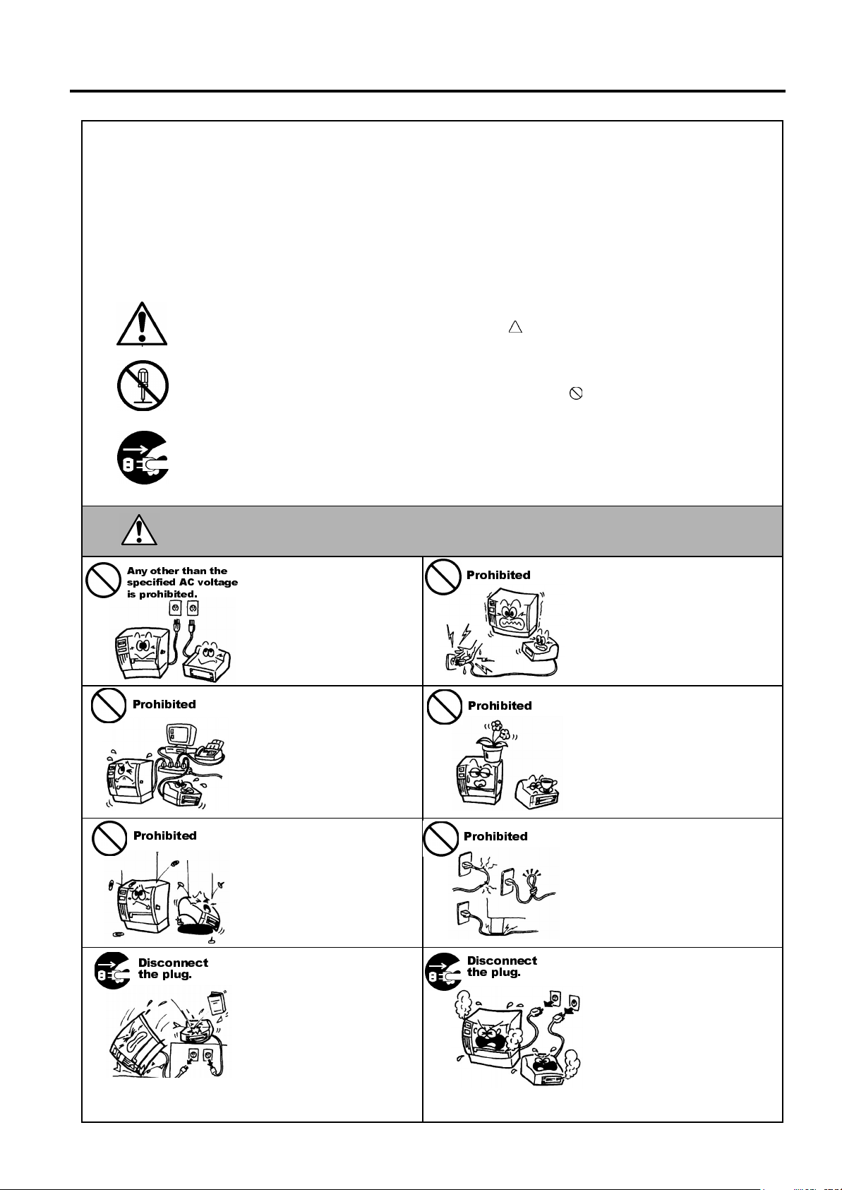
:$51,1*
Do not use voltages other than
the voltage (AC) specified on th e
rating plate, as thi s may cause
or
fire
electric shock
If the machines share the same
outlet with any other electrical
appliances which consume large
amounts of power, the voltage
will fluctuate widely each time
these appliances operate. Be sure
to provide an exclusive outlet for
the machine as this may cause
or
fire
electric shock
Do not insert or drop metal,
flammable or other foreign
objects into th e machines through
the ventilation slits, as this may
cause
fire
or
electric shock
This indicates that there is the risk of death or serious injury if the
machines are improperly handled contrary to this indication.
3URKLELWHG
.
3URKLELWHG
.
3URKLELWHG
.
Do not plug in or unplug the power
cord plug with wet hands as this
may cause
Do not place metal objects or
water-filled containers such as
flower vases, flower pots or mugs,
etc. on top of the machines. If
metal objects or spilled liquid enter
the machines, this may cause
or
Do not scratch, damage or modify
the power cords. Also, do not
place heavy objects on, pull on, or
excessively bend the cords, as this
may cause
electric shock
electric shock
or
fire
.
.
electrical shock.
fire
'LVFRQQHFW
WKH SOXJ
If the machines are dropped or
their cabinets damaged, first turn
off the power switches and
disconnect the power cord plugs
from the outlet, and then contact
your authorized TOSHIBA TEC
representative for assistance.
Continued use of the machine in
that condition may cause
electric shock
.
fire
or
'LVFRQQHFW
WKH SOXJ
Continued use of the machines in
an abnormal condition such as
when the machines are producing
smoke or strange smells may cause
or
fire
electric shock
cases, immediately turn off the
power switches and disconnect the
power cord plugs from the outlet.
Then, contact your au thorized
TOSHIBA TEC representative for
assistance.
. In these
( ) i
Safety Summary
EO1-33030
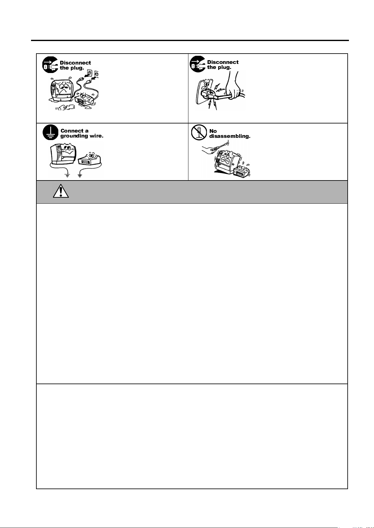
'LVFRQQHFW
WKH SOXJ
&RQQHFW D
JURXQGLQJ ZLUH
If foreign objects (metal
fragments, water, liquids) enter
the machines, first turn off the
power switches and disconnect
the power cord plugs from the
outlet, and then contact your
authorized TOSHIBA TEC
representative for assistance.
Continued use of the machine in
that condition may cause
electric shock
Ensure that the equipment is
properly grounded. Extension
cables should also be grounded.
Fire
or
occur on improperly grounded
equipment.
.
electric shock
fire
could
or
'LVFRQQHFW
WKH SOXJ
1R
GLVDVVHPEOLQJ
When unplugging the power cords,
be sure to hold and pull on the plug
portion. Pulling on the cord portion
may cut or expose the internal wires
fire
and cause
Do not remove covers, repair or
modify the machine by yourself.
You may be
voltage, very hot parts or sharp
edges inside the machin e.
electric shock
or
injured
by high
&$87,21
This indicates that there is the risk of personal
Injury
objects if the machines are improperly handled contrary to this indication.
damage
or
Precautions
The following precautions will help to ensure that this machine will continue to function correctly.
●
Try to avoid locations that have the following adverse conditions:
* Temperatures out of the specification * Direct sunlight * High humidity
* Shared power source * Excessive vibration * Dust/Gas
●
The cover should be cleaned by wiping with a dry cloth or a cloth slightly dampened with a mild
detergent solution. NEVER USE THINNER OR ANY OTHER VOLATILE SOLVENT on the plastic
covers.
●
USE ONLY TOSHIBA TEC SPECIFIED paper and ribbons.
●
DO NOT STORE the paper or ribbons where they might be exposed to direct sunlight, high
temperatures, high humidity, dust, or gas.
●
Ensure the printer is operated on a level surface.
●
Any data stored in the memory of the printer could be lost during a printer fault.
●
Try to avoid using this equipment on the same power supply as high voltage equipment or equipment
likely to cause mains interference.
●
Unplug the machine whenever you are working inside it or cleaning it.
●
Keep your work environment static free.
●
Do not place heavy objects on top of the machines, as these items may become unbalanced and fall
causing injury.
●
Do not block the ventilation slits of the machines, as this will cause heat to build up inside the
machines and may cause fire.
●
Do not lean against the machine. It may fall on you and could cause injury.
●
Care must be taken not to injure yourself with the printer paper cutter.
●
Unplug the machine when it is not used for a long period of time.
to
.
Request Regarding Maintenance
●
Utilize our maintenance services.
After purchasing the machine, contact your authorized TOSHIBA TEC representative for assistance
once a year to have the inside of the machine cleaned. Otherwise, dust will build up inside the
machines and may cause a fire or a malfunction. Cleaning is particularly effective before humid rainy
seasons.
●
Our preventive maintenance service performs the periodic checks and other work required to maintain
the quality and performance of the machines, preventing accidents beforehand.
For details, please consult your authorized TOSHIBA TEC representative for assistance.
●
Using insecticides and other chemicals
Do not expose the machines to insecticides or other volatile solvents. This will cause the cabinet or
other parts to deteriorate or cause the paint to peel.
( ) ii

EO1-33030
TABLE OF CONTENTS
Page
1. PRODUCT OVERVIEW.......................................................................................................... 1-1
1.1 Introduction.................................................................................................................... 1-1
1.2 Features ........................................................................................................................ 1-1
1.3 Unpacking......................................................................................................................1-1
1.4 Accessories .................................................................................................................. 1-2
1.5 Appearance ................................................................................................................... 1-2
1.5.1 Dimensions.....................................................................................................................1-2
1.5.2 Front View.......................................................................................................................1-3
1.5.3 Rear View.......................................................................................................................1-3
1.5.4 Interior............................................................................................................................. 1-3
1.5.5 Operation Panel..............................................................................................................1-4
2. PRINTER SETUP ................................................................................................................... 2-1
2.1 Precautions.................................................................................................................... 2-1
2.2 Procedure before Operation........................................................................................... 2-2
2.3 Connecting the Cables to Your Printer........................................................................... 2-2
2.4 Connecting the Power Cord........................................................................................... 2-3
2.5 Turning the Printer ON/OFF........................................................................................... 2-4
2.5.1 Turning ON the Printer...................................................................................................2-4
2.5.2 Turning OFF the Printer .................................................................................................2-4
2.6 Opening/Closing the Media Cover..................................................................................2-5
2.7 Loading the Media ......................................................................................................... 2-6
2.7.1 Loading the Fanfold Paper.............................................................................................2-7
2.7.2 Loading the Cut Form.....................................................................................................2-8
2.8 Removing/Installing the Paper Guide Unit...................................................................... 2-9
2.9 Test Print ..................................................................................................................... 2-10
2.10 Program Download...................................................................................................... 2-13
2.10.1 Outline of Features...........................................................................................2-13
2.10.2 Install Program Installation...............................................................................2-13
2.10.3 Firmware Files Copy ........................................................................................ 2-17
2.10.4 Sensor Adjustments......................................................................................... 2-23
2.10.5 Printer Information Registration........................................................................ 2-26
2.10.6 Test Print.......................................................................................................... 2-28
2.10.7 Version Display................................................................................................ 2-29
3. MAINTENANCE .....................................................................................................................3-1
3.1 Cleaning ........................................................................................................................ 3-1
3.1.1 Print Head/Platen ...........................................................................................................3-1
3.1.2 Paper Path/Sensors.......................................................................................................3-2
3.1.3 Covers ............................................................................................................................3-2
3.2 Care/Handling of the Media ........................................................................................... 3-2

EO1-33030
A
y
4. TROUBLESHOOTING............................................................................................................ 4-1
4.1 LED State...................................................................................................................... 4-1
4.2 Error Process.................................................................................................................4-2
4.3 Possible Problems.........................................................................................................4-3
4.4 Removing Jammed Media............................................................................................. 4-3
APPENDIX 1 SPECIFICATIONS.................................................................................................A1-1
A1.1 Printer..........................................................................................................................A1-1
A1.2 Media...........................................................................................................................A1-2
A1.2.1 Media Type.......................................................................................................A1-2
APPENDIX 2 INTERFACE ..........................................................................................................A2-1
APPENDIX 3 PRINT SAMPLES..................................................................................................A3-1
GLOSSARIES
INDEX
WARNING!
This is a Class A product. In a domestic environment t his product may cause radio interference
in which case the user may be required to take adequat e m easur es.
CAUTION!
1. This manual may not be copied in whole or in part without prior writt en per m ission of TO SHIB
TEC.
2. The contents of this manual may be changed without notification.
3. Please refer to your local author ized service representat ive with regard to any queries you ma
have in this manual.

1. PRODUCT OVERVIEW
EO1-33030
1. PRODUCT OVERVIEW
1.1 Introduction
1.2 Features
1.3 Unpacking
1. Check for damage or
scratches on the printer.
However, please note that
TOSHIBA TEC shall have
no liability for any damage
of any kind sustained during
transportation of the
product.
2. Keep the cartons and
packaging for future
transportation of the
printer.
NOTES:
Thank you for choosing the TEC B-419 series label printer. This
Owner’s Manual contains information about general set-up through how
to confirm the printer’s operation using a test print. This manual should
be read carefully to help gain maximum performance and life from your
printer. For most queries please refer to this manual and keep it safe for
future reference. Please contact your TOSHIBA TEC representative for
further information concerning this manual.
The B-419 printer has the following features:
• The paper auto feed function is provided for the first time for a 4 inch
wide, small and light desk top printer.
• To meet various applications, four types of issue modes, such as, the
TEC Printer Command Language Light Edition (TPCL-LE) mode,
high speed graphic mode, label issue mode, and receipt issue mode,
are supported as standard.
For details, please inquire from your nearest TOSHIBA TEC
representative.
• This printer can print cut forms as standard, which allows ticket
issuing.
Unpack the printer as per the Unpacking Instructions supplied with the
printer.
1.1 Introduction
1- 1
1. PRODUCT OVERVIEW
EO1-33030
1.4 Accessories
1.5 Appearance
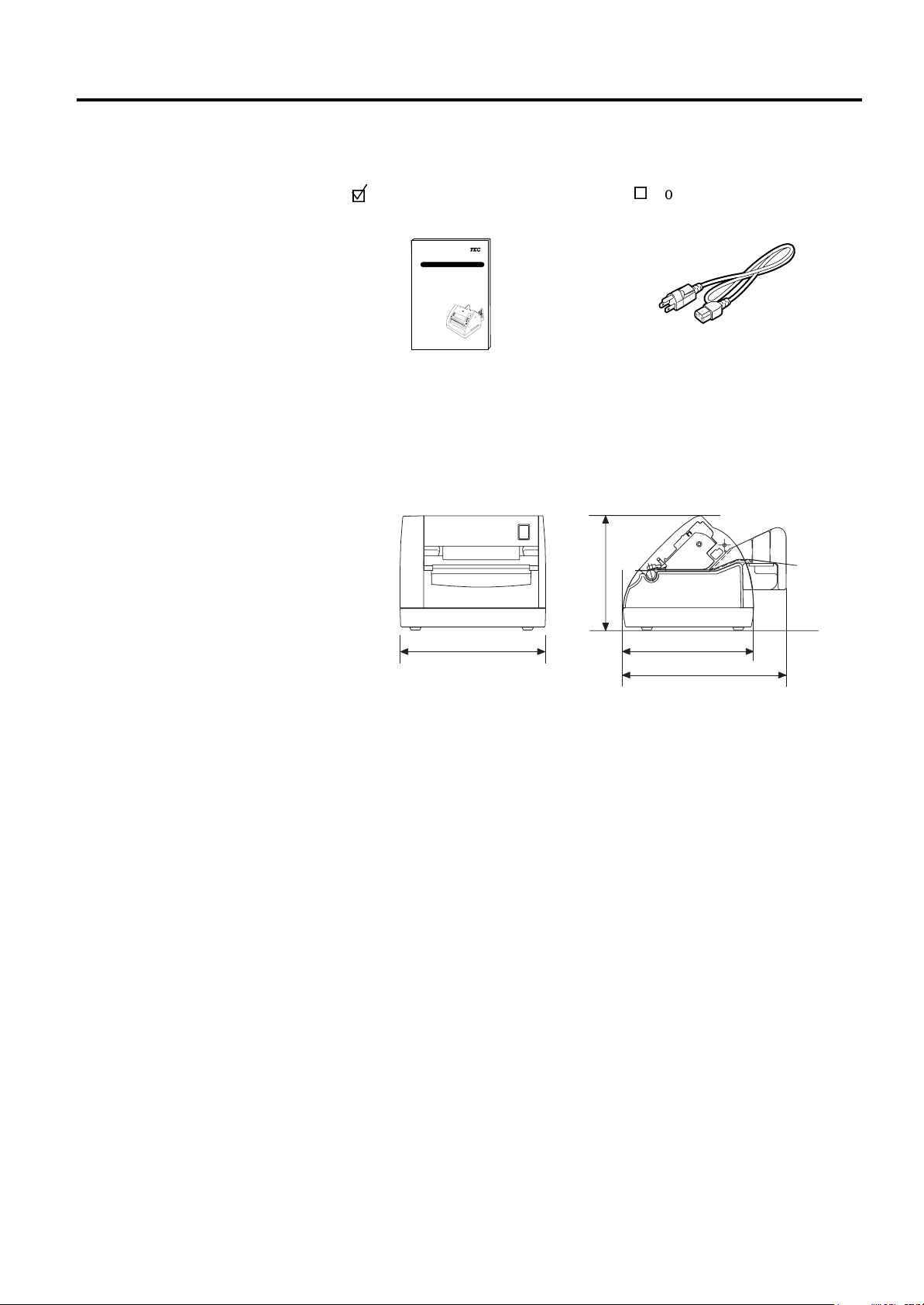
1.5.1 Dimensions
1.4 Accessories
When unpacking the printer, please make sure all the following
accessories have been supplied with the printer.
Owner’s Manual (1 copy)
(Doc./No. EO1-33030)
TEC Label Printer
B-419-GS10-QQ
Owner's Manual
Power Cord (1 pc.)
(P/No.FBCB0030202)
TOSHIBA TEC CORPORATION
The names of the parts or units introduced in this section are used in the
following chapters.
5.1(130)
6.6(167)
5.9(150)
7.4(187)
Dimensions in inch+(mm)
1- 2
1. PRODUCT OVERVIEW
EO1-33030
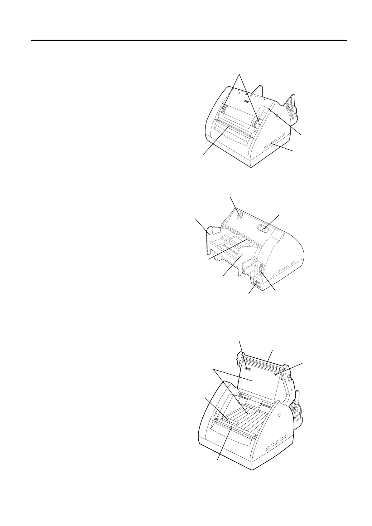
1.5.2 Front View
1.5.3 Rear View
1.5.4 Interior
1.5 Appearance
Media Cover
Release Catch
Media Outlet
Media Cover
Ventilator
FEED Button
Paper Guide (R)
Stand-by Switch
Media Inlet
Paper Guide (L)
Inlet
Serial Interface
Connector (RS-232C)
Feed Gap Sensor
Print Head
Paper Path Surface
Thermistor
Black Mark/
Feed Gap Sensor
1- 3
Platen
1. PRODUCT OVERVIEW
EO1-33030
1.5.5 Operation Panel
CAUTION!
Even if the Stand-by
switch is turned off, the
primary power remains
ON, as this switch turns
on/off the secondary
power supply only.
When the printer is not
used for a long time,
disconnect the power cord
from the AC outlet.
1.5 Appearance
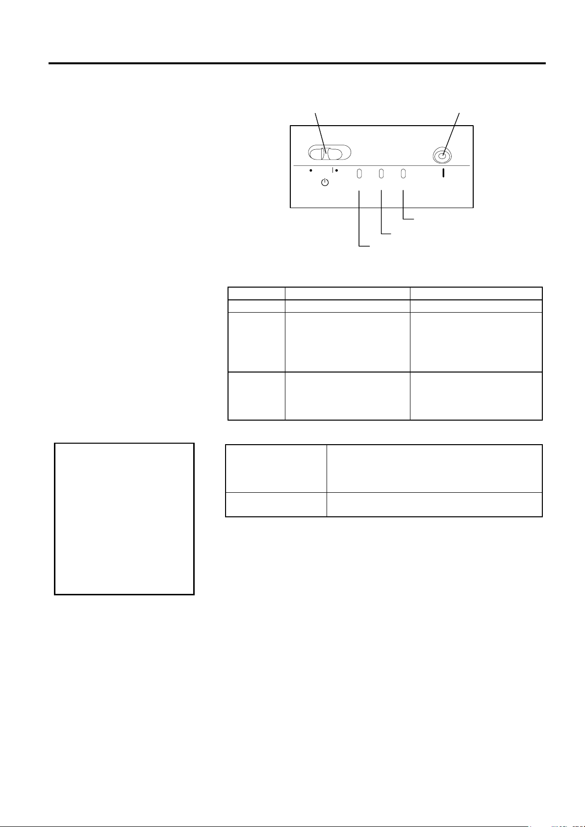
The figure below illustrates the Operation Panel and key functions.
Stand-by Switch
FEED Button
ON LINE
DATA
ERROR
FEED
ON LINE LED
ERROR LED
DATA LED
There are three LED lights on the Operation Panel.
LED Illuminates when… Flashes when…
ON LINE The printer is turned on. -----
The printer is in operation.
(Goes off when in Idle.)
DATA
Flashes fast when the printer
is communicating with the
PC.
Flashes slowly when the
print data remains.
ERROR
The print head has a
broken element.
Paper feed jam, cover open,
communication error, etc.
occurs. For details, refer to
Section 4.1 LED State.
There are two switches on the Operation Panel.
A slide power switch. The power is turned ON
STAND-BY Switch
when the switch is positioned to the (l) side.
The power is turned OFF when the switch is
positioned to the other side.
FEED Button
Each time this button is pressed, the printer
feeds one piece of media.
1- 4

2. PRINTER SETUP
EO1-33030
2. PRINTER SETUP
2.1 Precautions
2.1 Precautions
This section outlines the procedures to setup your B-419 printer prior to
its operation. The section includes precautions, connecting cables,
assembling accessories, loading media, and performing a test print.
To ensure the best operating environment, and to assure the safety of the
operator and the equipment, please observe the following precautions.
• Operate the printer on a stable, level, operating surface in a location
free from excessive humidity, high temperature, dust, vibration or
direct sunlight.
• Keep your work environment static free. Static discharge can cause
damage to delicate internal components.
• Make sure that the printer is connected to a clean source of AC
Power and that no other high voltage devices that may cause line
noise interference are connected to the same mains.
• Ensure that the printer is connected to the AC mains with a three-
prong power cable that has the proper ground (earth) connection.
• Turn off the printer power and remove the power cord from the
printer whenever working on the inside of the printer such as loading
the media, or when cleaning the printer.
• For best results, and longer printer life, use only TOSHIBA TEC
recommended media.
• Store the media in accordance with the specifications.
• This printer mechanism contains high voltage components; therefore
you should never remove any of the covers of the machine as you
may receive an electrical shock. Additionally, the printer contains
many delicate components that may be damaged if accessed by
unauthorized personnel.
• Clean the outside of the printer with a clean dry cloth or a clean cloth
slightly dampened with a mild detergent solution.
• Use caution when cleaning the thermal print head as it may become
very hot while printing. Wait until it has had time to cool before
cleaning.
• Do not turn off the printer power or remove the power plug while the
printer is printing or while the ON LINE lamp is blinking.
• Ensure that there is an AC outlet that can be used only for the printer
close to the printer installation location.
2- 1
2. PRINTER SETUP
o
EO1-33030
2.2 Procedure before
Operation
1. To communicate with the
host computer, a 9-pin RS232C cable is required.
2. The printer can also be
controlled with its own
programming commands.
Please contact your
TOSHIBA TEC reseller for
the Interface/Communication
Manual.
NOTES:
2.3 Connecting the
Cables to Your
Printer
The RS-232C must be
connected while the power
is turned OFF. Failure to d
this may cause electric
shock or short-circuit.
CAUTION!
2.2 Procedure before Operation
This section describes the outline of the printer setup.
1.
Unpack the accessories and printer from the box.
2.
Refer to Safety Precautions in this manual and set up the printer in a
suitable location.
3.
The host computer must have a serial port. (Refer to Section 2.3.)
4.
Be sure to insert the power cord plug into an AC outlet. (Refer to
Section 2.4.)
5.
Load the media in the printer. (Refer to Section 2.7.)
6.
Turn the Power ON. (Refer to Section 2.5.)
7.
Perform a test print. (Refer to Section 2.9.)
8.
Install the Printer Drivers.
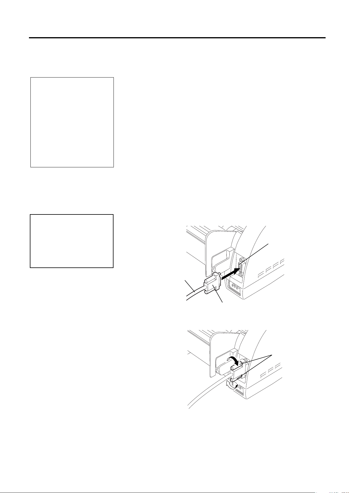
When connecting the RS-232C cable to your printer, follow the
procedure described below.
1.
Make sure that the power cord is not connected to the AC outlet.
2.
Connect the printer side connector of the RS-232C cable to the serial
port on the rear of the printer.
Serial Port
RS-232C Cable
Connector
3.
Secure the connector with the screws.
Screw
4.
Connect the PC side connector of the RS-232C cable to the Serial
port of your PC.
2- 2
2. PRINTER SETUP
g
EO1-33030
2.4 Connecting the
Power Cord
1. Make sure that the
2. Use only the power cord
3. Connect the power cord
4. Even if the Stand-by
CAUTION!
printer Stand-by switch
is turned to the off
position before
connecting the power
cord to prevent possible
electric shock or
damage to the printer.
supplied with the printer.
Use of any other cord
may cause electric
shock or fire.
to a three-prong outlet
only, with the third pron
being a good ground
(earth) connection.
switch is turned off, the
primary power remains
ON, as this switch turns
on/off the secondary
power supply only.
When the printer is not
used for a long time,
disconnect the power
cord from the AC outlet.
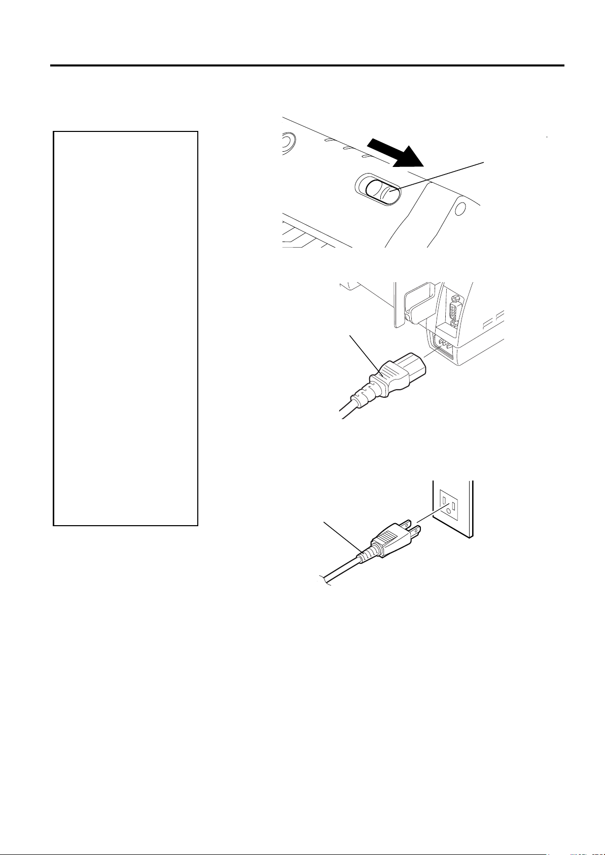
2.4 Connecting the Power Cord
1
. Make sure that the Stand-by switch is in the OFF position.
Stand-by Switch
2.
Connect the Power Cord to the printer as shown in the figure below.
Power Cord
3.
Plug the other end of the Power Cord into the ground outlet as
shown in the figure below.
Power Cord
2- 3
2. PRINTER SETUP
e
EO1-33030
2.5 Turning the Printer
ON/OFF
2.5.1 Turning ON the Printer
Use the Stand-by switch
to turn the printer On/Off.
Plugging or unplugging
the power cord to turn th
printer On/Off may cause
fire, an electric shock, or
damage to the printer.
When the ERROR LED is
illuminated, refer to Section
4.1 LED State.
2.5.2 Turning OFF the Printer
1. Do not turn off the
2. Do not turn off the
CAUTION!
printer power while the
media is being printed
as this may cause a
paper jam or damage
to the printer.
printer power while the
ON LINE light is
blinking as this may
cause damage to your
computer.
NOTE:
CAUTION!
2.5 Turning the Printer ON/OFF
When the printer is connected to your host computer it is good practice to
turn the printer ON before turning on your host computer and turn OFF
your host computer before turning off the printer.
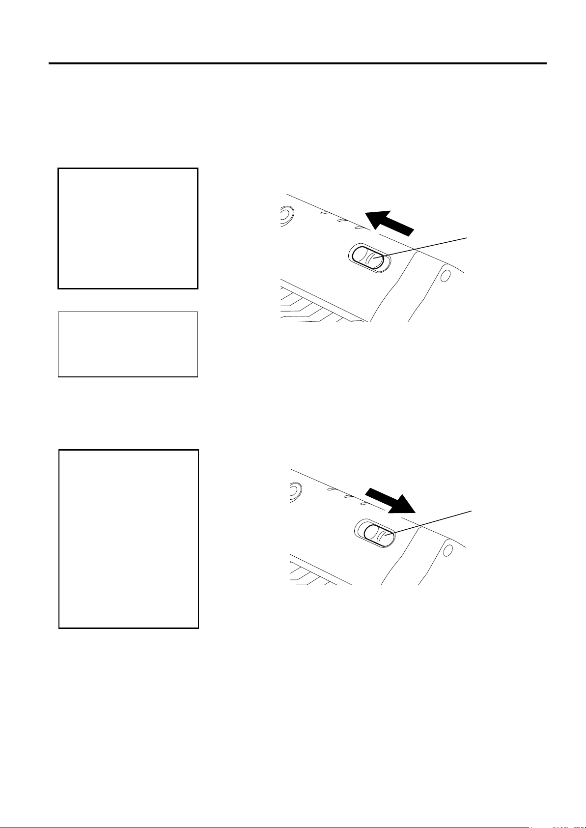
1.
To turn ON the printer power, slide the Stand-by switch as shown in
the diagram below. Note that ( l )
switch.
2.
Check that the
1.
To turn OFF the printer power, slide the Stand-by switch as shown
in the diagram below. Note that no mark is printed on the power
OFF side.
ON LINE
ON
LED is illuminated.
is the power ON side of the
Stand-by Switch
OFF
Stand-by Switch
2- 4
2. PRINTER SETUP
jury
EO1-33030
2.6 Opening/Closing
the Media Cover
The Media Cover should
be opened fully. Failure
to do this may cause the
Media Cover to close by
its weight, resulting in
in
WARNING!
.
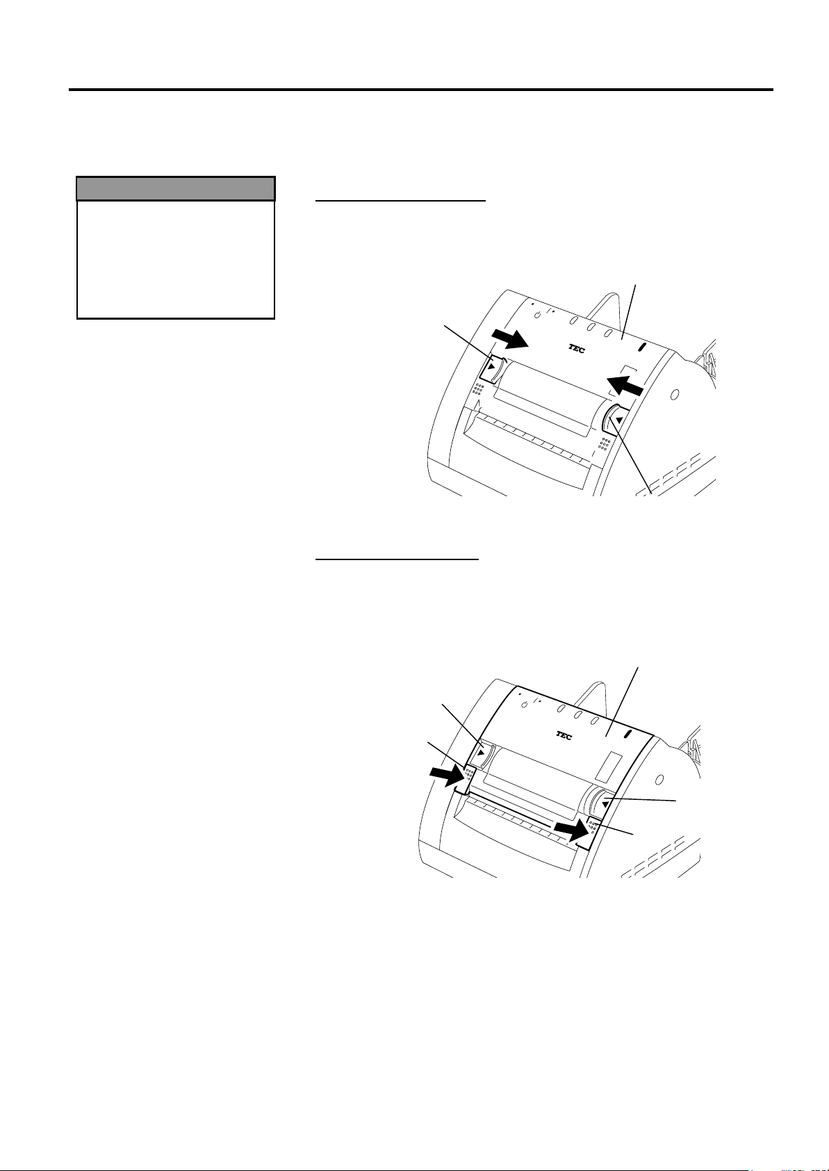
2.6 Opening/Closing the Media Cover
This section describes the opening and closing procedure of the Media
Cover. Follow the procedure when cleaning the print head, platen, paper
passage, or media sensor, or removing jammed paper.
Opening the Media Cover
1.
Release the Media Cover by pushing both sides of the Media Cover
Release Catches toward the center, and then open the Media Cover.
Media Cover
Release Catch
Media Cover
Media Cover
Closing the Media Cover
Release Catch
1.
Close the Media Cover by pressing portions (A) until they click.
2.
Make sure that both Media Cover Release Catches are in position
and the Media Cover is locked.
Media Cover
Release Catch
(A)
Media Cover
Media Cover
Release Catch
(A)
2- 5
2. PRINTER SETUP
EO1-33030
2.7 Loading the Media
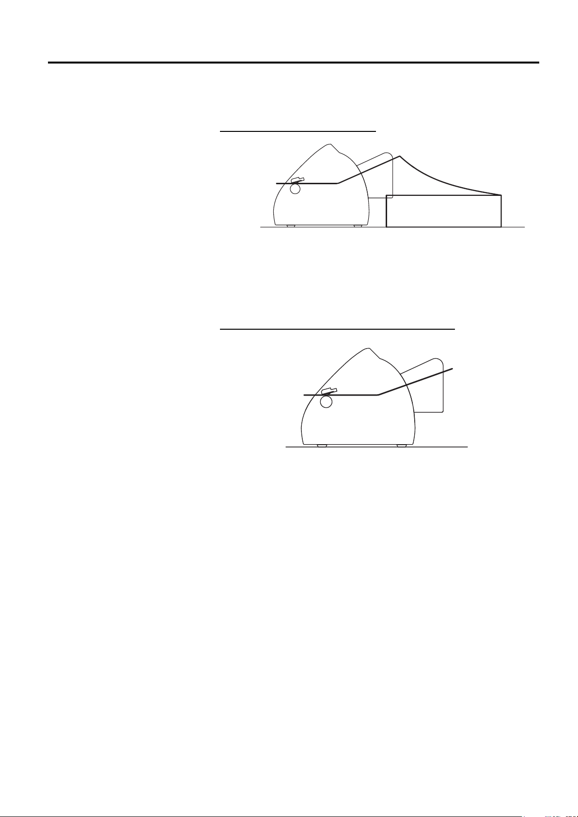
2.7 Loading the Media
The B-419 printer issues in two issue modes depending on the media
types.
Continuous mode (Fanfold paper)
• Insert the media through the media inlet, or open the media cover and
set the media, and then close the media cover.
• When the print command is received from the PC, the specified
numbers of media are printed continuously.
• Pressing the
[FEED]
button causes one piece of media to be fed.
Cut form mode (When the auto-feed is turned ON.)
• Insert the media through the media inlet, or open the media cover and
set the form, and then close the media cover. The media is
automatically fed to the print start position.
• When the print command is received from the PC, the specified
numbers of media are printed one by one.
• When unprinted data remains after issuing the media, the DATA LED
flashes slowly (indicating the printer is waiting for media supply.)
• Pressing the
[FEED]
button causes one piece of media to be fed.
2- 6
2. PRINTER SETUP
D
D
p
p
f
EO1-33030
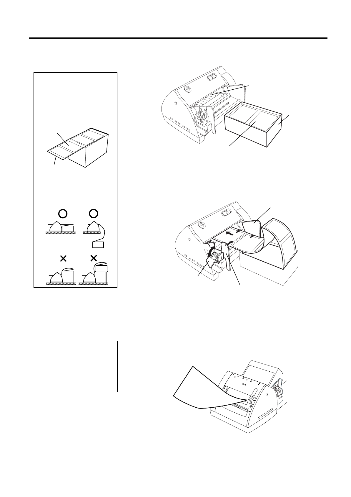
2.7.1 Loading the Fanfold
Paper
1. Place the fanfold paper so
that the print surface faces
up and the top edge of the
paper is positioned at the
printer side.
Print Surface
Paper Top Edge
2. Place the fanfold paper on
the surface below the
position of the printer’s
media inlet.
NOTES:
2.7 Loading the Media
1.
Place the fanfold paper at the rear of the printer in line.
Media Inlet
Container
2.
Place the paper top edge in front of the Media Inlet, and align the
Fanfold Paper
left paper edge with the Paper Guide (L). Push the Paper Guide
Release Lever outside, and align the Paper Guide (R) with the right
paper edge.
3.
Lock the Paper Guide by pulling the Paper Guide Release Lever up.
Paper Guide (L)
Lock
Release
Paper Guide
Release Lever
Paper Guide (R)
4.
Turn the PC power ON, and then turn the printer power ON.
5.
Insert the paper top edge into the Media Inlet until it stops. Pressing
[FEED]
NOTE:
o not pull the printed paper.
oing so may dislocate the
rinter or misalign the print
osition, causing a print
ailure.
the
6.
Send a print data from the PC.
7.
The data is printed on the paper. Tear off the printed paper at the
edge of the Media Outlet.
button feeds one piece of the paper.
2- 7

2. PRINTER SETUP
p
p
y
f
M
d
R
EO1-33030
2.7.2 Loading the Cut Form
The AUTO FEED function is
available when selected by the
rinter setting and black marks
are printed on the media as
shown below. For details of the
rinter setting, please contact
our nearest TOSHIBA TEC
representative.
To activate the AUTO FEED
unction, insert the black mark
side of the media into the
edia Inlet until it stops. The
media will be automatically fe
to the print start position.
everse side of the media
NOTE:
Black Mark
2.7 Loading the Media
1.
Place the paper top edge in front of the Media Inlet, and align the
left paper edge with the Paper Guide (L). Push the Paper Guide
Release Lever outside, and align the Paper Guide (R) with the right
paper edge.
2.
Lock the Paper Guide by pulling the Paper Guide Release Lever up.
Paper Guide (L)
Lock
Release
3.
Turn the PC power ON, and then turn the printer power ON.
4.
Insert the paper top edge into the Media Inlet until it stops.
5.
Send a print data from the PC. The data is printed on the paper
Paper Guide
Release Lever
Paper Guide (R)
2 -8

2. PRINTER SETUP
B
EO1-33030
2.8 Removing/Installing
the Paper Guide Unit
NOTE:
e careful not to overtighten
the screws of the Paper Guide
Unit. The screw holes may be
damaged.
2.8 Removing/Instal l i ng the Paper Guide Unit
When using 4.3” (109 mm) wide media, remove the Paper Guide
Assembly as follows.
1.
Make sure that the Power Cord is not connected to the AC outlet.
2.
Press the Paper Guide Release Lever outside and move the Paper
Guide (R) toward the center.
Paper Guide Release Lever
Paper Guide (R)
3.
Remove the two screws to detach the Paper Guide Unit from the
printer.
Paper Guide Unit
4.
When changing the media to less than 4.2” (106 mm) wide one,
install the Paper Guide Unit in the reverse order of removal
described above.
2- 9

2. PRINTER SETUP
EO1-33030
2.9 Test Print
2.9 Test Print
The following test procedure allows you to perform a print test to verify
that the printer is operating correctly.
1.
Load the media on the printer.
2.
Slide the Stand-by Switch to ON while holding the
[FEED]
button.
The printer will start a status print.
(10)
(11)
(12)
(13)
(14)
(1)
(2)
(3)
(4)
(5)
(6)
(7)
(8)
(9)
3.
After completing the status print, the test pattern is printed each time
[FEED]
the
button is pressed.
2- 10

2. PRINTER SETUP
EO1-33030
2.9 Test Print (Cont.)
NOTE:
Each form version: 0 to 9
2.9 Test Print
• Test Print Definitions
(1) Software Version and Checksums
PROGRAM VERSION FMRM0064101 V1.0 EB00 (FONT:0200) (BOOT: F800)
Software Number
Version
Program Checksum
C/G Area Checksum
Boot Area Checksum
(2) Printer ID Number
PRINTER ID 00000
Printer ID No.
(3) Form Version No. 40
FORM VERSION 1110000000 0000000001 0000000000 0000000000
Form No. 01 version
Form No. 40 version
(4) SRAM Capacity
SRAM CHECK 512KB
Read/Write RAM capacity
(5) Sensor Status
SENSOR CHECK R:2.9V T:0.7V F:2.9V H:+34°C A:+30°C
Black Mark Sensor
(0.0V to 3.3V)
Feed Gap Sensor
(0.0V to 3.3V)
Black Mark Sensor
(for Auto Feed Function)
(0.0V to 3.3V)
(-10°C to +70°C)
(-10°C to +70°C)
(6) Print Tone
TONE ADJUST +00
Print tone fine adjustment (-10 to +10)
(7) Print Start Position
FEED ADJUST +0.0mm
Head Temperature
Ambient Temperature
Print position fine adjustment
(-10mm to +10mm)
2- 11

2. PRINTER SETUP
j
EO1-33030
2.9 Test Print (Cont.)
NOTE:
For this check a loopback jig is
required. Performing a loop
back check without this jig will
result in NG. For the loopback
ig, please contact your nearest
TOSHIBA TEC service
representative.
2.9 Test Print
(8) Back Feed Position
BACK FEED ADJ. +0.0mm
Back feed fine adjustment for the initial feed
(-9.9mm to +9.9mm)
(9) Print Head Element Check
HEAD CHECK OK
Result of print head broken elements check
(OK: Normal, NG: Broken element)
(10) Printing Mode
PRINT MODE TPCL-LE (AUTO FEED: OFF)
Auto feed function
ON: with auto feed
OFF: without auto feed
Issue mode
TPCL-LE: TPCL-LE mode
GRAPHIC: High speed graphic mode
LABEL: Label issue mode
RECEIPT: Receipt issue mode
(11) Loop Back Check
LOOP BACK CHECK NG
Result of RTS-CTS loop back check
OK: OK
NG: NG
(12) Printer Parameter
PARAMETER [B-419(QQ/QP)] [PC-850] [0]
Character code and font zero selection
(13) Model Name
MODEL NAME B-419(QQ/QP) Series
May be changed by printer
information registration procedure via
download from PC.
(14) Comment Print Area
COMMENT Jul/15/2001
Comment (Printed only when a comment was
entered during the program download.)
2- 12

2. PRINTER SETUP
EO1-33030
2.10 Program Download
2.10.1 Outline of Features
2.10.2 Install Program
Installation
2.10 Program Download
This section provides step by step instructions on how to setup and
download the firmware to the B-419 printer, and to make adjustments to
the printer sensors. The firmware download and the sensor adjustments
will be made from a Personal Computer via the RS-232C interface.
The software for performing the program download will allow the
download of the Firmware (Application Program including Boot
Program, and Character Generator) from the provided FDK, allow
adjustments to printer sensor sensitivity, and allow the download of the
Printer Information. The software will be run on a standard PC and
communication to the B-419 printer will be via the RS-232C cable.
Firmware Download - The Application Program, and Character
Generator are installed into the B-419 printer's Flash memory prior to
being shipped to the customer. However, if specifications should change
at a later date, this software will allow downloading firmware updates to
the B-419 printer.
Sensor Adjustment - The various sensors within the printer have been
set at the factory before shipping. However, it may become necessary to
make adjustments to the sensitivity of one or more of these sensors to
compensate for factors such as different label backing paper thickness,
opaqueness, etc. These adjustments can be made from a PC
communicating with the B-419 printer via the RS-232C interface.
Printer Information Registration - This portion of the software allows
you to download printer information from a standard PC to the printer's
memory. The printer information consists of the model name and printer
type. The printer will operate according to the selection of printer model
and printer type. These data will print out on diagnostic labels issued
from the printer.
Test Print - This portion of the software allows you to perform a test
print from a PC.
Before you can communicate from your PC to the B-419 printer, you
must first copy the "Install Program for B-419" from the three FDKs
provided to the hard disk of your PC.
SETUP DISK (1/3)
Install Program for B-419 Standard
15th June 2001
FMRM0064201
V001.000
Copyright ©2001
TOSHIBA TEC CORPORA T ION
All Rights Reserved
2-13

2. PRINTER SETUP
EO1-33030
2.10.2 Install Program
Installation (Cont.)
Windows 3.1® is not supported.
Windows 95®, Windows 98®,
Windows 2000®, and Windows
3.1® are registered trademarks
of the Microsoft Corporation.
NOTE:
2.10 Program Download
• System Requirements
System
IBM Compatible PC running Windows 95®, Windows 98®, or Windows
2000®.
Installed memory of 16MB minimum (32MB or more recommended)
Available Hard Disk space of 10MB or more
Interface
Interface to the B-419 will be through an RS-232C interface.
More than one serial port should be provided on the PC.
• Setup
Setup Disk
Make sure that you have all three diskettes available of the “Install
Program for B-419”. (Refer to the figure on the previous page.)
1.
While running Windows 95, Windows 98 or Windows 2000, insert
Setup Disk (1/3) into the PC floppy drive.
2.
Click on the
3.
When the RUN display appears, type in A:\SETUP.EXE and click
on OK.
4.
When the installation is ready, the initial screen of the installation
will automatically appear.
START
button then highlight
RUN
and click on
RUN
.
2-14

2. PRINTER SETUP
EO1-33030
2.10.2 Install Program
Installation (Cont.)
2.10 Program Download
5
. The Software License Agreement screen will appear. Click on
when you agree.
6.
When the User Information screen appears, type in your name and
company name, then proceed to the next step.
7.
After click on
Next>
screen appears. Click on the
in the previous screen, the following message
Next>
button to accept the directory or
change the directory if desired.
Yes
2-15

2. PRINTER SETUP
EO1-33030
2.10.2 Install Program
Installation (Cont.)
2.10 Program Download
8.
The following program folder selection menu will appear. Click on
Next>
the
button.
9.
Confirm the current settings and click on the
Next>
button.
10.
The install process will begin.
11.
When requested, insert Setup Disk (2/3) and then the Setup Disk
(3/3).
2-16

2. PRINTER SETUP
I
y
I
EO1-33030
2.10.2 Install Program
Installation (Cont.)
2.10.3 Firmware Files Copy
f the Install Program for B-
419 has not been installed on
our PC yet, refer to Section
2.10.2 Install Program
nstallation and install it
before copying the firmware.
NOTE:
2.10 Program Download
12.
When the install process is completed, the following screen display
will appear. Click on the
Finish
button to end the installation.
If it ever becomes necessary to upgrade the firmware in the B-419 printer
you will be supplied with a floppy disk containing the latest firmware
revision similar to that shown below.
15th June 2001
FMRM0064101:7200(F800)
(FONT:0200)(KANJI:C900)
V001.000
B-419 Standard
FIRMWARE V1.0
FILE:S-V10-Z900.EXE
(PROGRAM: S-P-V10-72.BIN)
(FONT:S-C-V10-02.BIN)
(KANJI: S-K-V10-C9.BIN)
Copyright ©2001
TOSHIBA TEC CORPORA T ION
All Rights Reserved
• Copy Firmware Files to Hard Disk
The files contained on the Firmware FDK are self-decompressing files.
They must be copied to the following directories of the PC hard disk
before being transferred to the printer. When the “Install Program for B419” was installed onto your PC, it created the following directories:
C:\Program Files\TOSHIBATEC\B419STDDL\Firmware
Using Windows Explorer, copy all the files from the Firmware FDK to
the above directory and decompress them into binary files (*.BIN).
2- 17

2. PRINTER SETUP
EO1-33030
2.10.3 Firmware Files Copy
(Cont.)
2.10 Program Download
The following paragraphs will give step by step directions for running the
"Install Program for B-419" on your PC which will allow you to transfer
the binary files stored in directory C: \Program Files\TOSHIBATEC\
B419STDDL\Firmware to the flash memory of the B-419 printer.
Running the Install Program for B-419
•
1.
Click on the
2.
Highlight "Programs" then highlight "TOSHIBA TEC" and click on
START
button to access the program menu.
Install Program for B-419 Series as shown in the screen display
below
3.
As soon as you click on Install Program for B-419, the screen will
change to display the initial screen of the Install Program as shown
below.
4.
From the File (F) drop down menu select Open (O).
2- 18

2. PRINTER SETUP
L
\
EO1-33030
2.10.3 Firmware Files Copy
(Cont.)
The C:\Program Files\
TOSHIBATEC\B419STDD
Firmware folder is the
default directory.
NOTE:
2.10 Program Download
5.
The file open screen will appear as shown in the figure below.
Select the C:\Program Files\TOSHIBATEC\B419STDDL\
Firmware folder and the files in that folder will appear in the files
box.
6.
As soon as you highlight on the files in the files box, the right half of
the screen will show all the data concerning the selected file as
shown in the figure below.
7.
After highlighting the desired download file in the preceding screen
display, click on
OPEN
and the screen display shown in the figure
below will appear. Confirm the COM port conditions shown at the
right of the screen.
2- 19

2. PRINTER SETUP
f
EO1-33030
2.10.3 Firmware Files Copy
(Cont.)
1. The communications
settings should be set as
follows.
Download:
9600 bps to 115200 bps,
None parity
Sensor setting:
19200 bps, None parity
Printer information
registration:
19200 bps, None parity
Test Print:
19200 bps, None parity
2. The settings shown on the
display are the default.
This procedure is only used by
service personnel to download
a message along with the
irmware download. Be sure
to select Nothing.
NOTE:
NOTE:
2.10 Program Download
8.
If it is necessary to change any of the communication parameters,
select the Settings (S) drop down menu and then select Conditions
(S) as shown in the figure below.
9.
The communications setting window will appear as in figure below
to allow you to change the communication parameters. Set the
proper settings for Device, Parity, and Baud Rate, and click on OK
button.
10.
In the Settings drop down menu is another possible selection
labeled Comment (C ) as shown below. If Comment (C) is
selected then the comment selection menu appears. There are three
different settings that can be selected in this operation, Nothing,
Only Date, and Enter Some Comments. If nothing is selected no
comment is attached. If Only date is selected, then the PC date
will be attached as the message. If Enter Some Comments is
selected, a comment message of up to 16 characters can be
attached to the download, and will appear on the diagnostic
printout.
2- 20

2. PRINTER SETUP
I
EO1-33030
2.10.3 Firmware Files Copy
(Cont.)
NOTE:
When Nothing is selected,
“(none)” will be displayed
.
When Only Date is selected,
the current date will be
displayed.
When Enter Some Comments is
selected, a message of max. 16
characters can be entered.
f the file for downloading is
not opened, START (R) cannot
be selected.
NOTE:
NOTE:
NOTE:
2.10 Program Download
No comment will be sent.
PC date will be sent.
16 character maximum message can be sent.
11.
Click the OK button to continue.
Execution of Download to Printer
•
1.
After selecting a file for downloading in the previous steps, select
the Run (R) drop down menu then select and click on START (R) as
shown in the figure below.
2 -21

2. PRINTER SETUP
I
I
EO1-33030
2.10.3 Firmware Files Copy
(Cont.)
f the message screen does not
change, the printer failed to
enter the DOWNLOAD mode.
Turn on the printer power on
while pressing and holding the
FEED button again.
f an error occurs during
download or at the end of
download, retry from step 1.
NOTE:
NOTE:
2.10 Program Download
2.
After clicking on Start in the previous screen, the following message
will appear on the screen.
3.
At this time, connect the printer to the PC with the RS-232C cable.
Press and hold the FEED button while sliding the printer Stand-by
switch to ON. When the printer enters DOWNLOAD mode
successfully, the message screen will change to the following.
4.
Press the OK button on the preceding screen to begin the sending of
the Firmware file. During transmission, the following screen
appears with a progress indicator at the bottom.
5.
When the file has been successfully transferred, the message shown
below will appear.
2- 22

2. PRINTER SETUP
EO1-33030
2.10.4 Sensor Adjustments
1. These sensors have been
factory set so it is not
advisable for you to make
these adjustments unless
you are having a problem
with the printer.
2. If the sensor adjustment is
required, be sure to follow
the procedure as described.
Failure to do this may
cause a malfunction of the
printer.
3. Do not turn on the printer
with the media being set in
the printer. Doing so
causes the printer to feed
the media automatically,
and you cannot adjust the
sensor. To inactivate the
auto feed function during
the sensor adjustment, turn
the printer power on with
no media or with the media
cover open, and then click
on
NOTES:
Read A/D
button.
2.10 Program Download
Through the following procedure, it is possible to adjust the sensitivity of
the three sensors in the B-419 printer from your PC via the RS-232C
interface. The three sensors are the reflective (black mark) sensor, the
transmissive (feed gap) sensor, and the paper end sensor.
• Setup
To begin the sensor adjustment operation, you will need to turn on the
power of the B-419 printer (do not hold the feed key this time). Connect
the printer to the PC with the RS-232C cable. Select the TPCL-LE mode
for the printer issue mode. Then set the communications parameters as
follows:
19200 bps, None parity
• Start
1.
From the Install Program for B-419 main menu, select Options (O)
then select Sensor Adjustment (S) as shown in the figure below.
2.
After highlighting and clicking on Sensor Adjustment (S) from the
above display, the screen display will change to the Sensor
Adjustment menu. Click on the
now display the current sensor output values.
Read A/D
button. The screen will
2- 23

2. PRINTER SETUP
A
EO1-33030
2.10.4 Sensor Adjustments
(Cont.)
NOTE:
fter completing an adjustment
to any of the sensors the
Adjust
greyed out. However, it will
still be possible to make the
adjustment again even if the
Adjust
button will become
button is greyed out.
2.10 Program Download
• Adjustment Procedure
Reflective Sensor (Black Mark Sensor)
1.
T he reflective sensor is the one used to detect the black mark on the
back of certain types of print media. Place the media so that the
white part of the media (not the black mark) is positioned on the
sensor.
2.
From the Sensor Adjustment menu shown on the previous screen,
click on the
Adjust
button for the reflective sensor. The screen
display shown in the figure below will appear.
3.
Click on the
Yes
button and the sensitivity of the reflective sensor
will automatically be set as indicated by the “Now Adjusting”
window appearing as shown in the figure below.
Transmissive Sensor (Feed Gap Sensor)
1.
The transmissive sensor is the one used to detect the gap between
labels. It detects the transmission of light through the backing paper
of different opaqueness. Place the media so that the backing paper
(not the label) is positioned over the transmissive sensor.
2.
From the Sensor Adjustment menu shown on the previous page,
click on the
Adjust
button for the transmissive sensor. The screen
display shown in the figure below will appear.
2- 24

2. PRINTER SETUP
EO1-33030
2.10.4 Sensor Adjustments
(Cont.)
2.10 Program Download
3.
Click on the
sensor will automatically be set as indicated by the “Now Adjusting”
window appearing as shown in the figure below.
Paper End Sensor
1.
The paper end sensor will detect when the print media has run out.
To adjust this sensor, remove the media from the printer and click on
Adjust
the
Adjustment menu.
2.
The screen display shown in the figure below will appear.
3.
Click on the
will automatically be set as indicated by the “Now Adjusting”
window appearing as shown in the figure below.
Yes
button and the sensitivity of the transmissive
button for the paper end level sensor on the Sensor
Yes
button and the sensitivity of the paper end sensor
2- 25

2. PRINTER SETUP
r
I
p
EO1-33030
2.10.5 Printer Information
Registration
This information is stored in
rinter memory before
delivery to the customer, so
this procedure need only be
done if it is required to
change any of the
information.
When the entire serial
number is entered, the printe
D will appear automatically.
NOTE:
NOTE:
2.10 Program Download
This procedure will be used to register (transfer) printer information to
the printer memory and the information registered here will also be
printed on every diagnostic print issued from the printer. The
information to be registered will be the printer model name and the
printer type.
• Procedures
1.
To perform this operation, you will need to turn on the power of the
B-419 printer (do not hold the feed key this time). Connect the
printer to the PC with the RS-232C cable. Select the TPCL-LE
mode for the printer issue mode. Then set the communications
parameters as follows:
2.
From the Install Program for B-419 main menu, select Options (O)
3.
After selecting Printer Information Store (P), the screen will change
19200 bps, None parity
and Printer Information Store (P) as shown in the screen display of
the figure below.
to the display shown below.
2- 26

2. PRINTER SETUP
M
M
N
p
M
I
EO1-33030
2.10.5 Printer Information
Registration (Cont.)
odel Name is automatically
displayed by selecting the
odel. To change the Model
ame click on the Default
check box to remove the check
mark and it will then be
ossible to type in a new
odel Name of up to 20
characters.
NOTE:
f the Complete screen does
not appear, retry from step 1.
NOTE:
2.10 Program Download
4.
Click on the QQ/QP check box for the Model on the Printer
Information Store display. Depending on the selected model, the
printer changes the communication requirements and other internal
functions.
5.
When the desired changes have been made, click on the OK button
and the following screen display will appear. Confirm the printer
information on the screen display, and click on
Yes
to start
registration.
6.
When the registration terminates successfully, the following display
will appear.
2- 27

2. PRINTER SETUP
EO1-33030
2.10.6 Test Print
1. The default settings are:
2. The size of the print image
for the test print has been
designed to fit to a 127 mm
pitch label. Therefore,
when using the paper of
shorter pitch, the print
image will breaks, or when
using the label of longer
pitch, a blank space will
remain.
3. Setting the different label
pitch from actual paper size
or using the paper with a
black mark printed on an
improper position may
cause an error.
NOTES:
Label Pitch: 127 mm
Print Count: 1
Sensor: Reflective
2.10 Program Download
This procedure will be used to perform a test print.
• Procedures
1.
To perform this operation, you will need to turn on the power of the
B-419 printer (do not hold the feed key this time). Connect the
printer to the PC with the RS-232C cable. Select the TPCL-LE
mode for the printer issue mode. Then set the communications
parameters as follows:
19200 bps, None parity
2.
From the Install Program for B-419 main menu, select Options (O)
and Test Print (T) as shown in the screen display of the figure below.
3.
When the following screen display appears, set the Label Pitch, Print
Count, and the Sensor, then click on the OK button.
A few seconds later, the printer will start the test print.
Reflective
2- 28

2. PRINTER SETUP
EO1-33030
2.10.7 Version Display
2.10 Program Download
This procedure will be used to check the version of the Install Program
for B-419 Standard.
• Procedures
1.
From the Install Program for B-419 main menu, select Help (H) and
Version (A) as shown in the screen display of the figure below.
2.
The Version screen display will appear as follows.
2- 29

3. MAINTENANCE
I
EO1-33030
3. MAINTENANCE
1. Be sure to disconnect the
2. To avoid injury, be
3. The Print Head m ay
4. Do not pour water directly
3.1 Cleaning
3.1.1 Print Head/Platen
1. Do not allow any hard
2. Do not use any volatile
3. Do not touch the print
4. Failure to clean the print
5. Failure to clean the
WARNING!
Power Cord before
performing maint enance.
Failure to do this may
cause an electric shock.
careful not to pinch or
jam your fingers while
opening or closing the
cover.
become hot. Do not
touch the Print Head.
onto the printer.
CAUTION!
objects to touch the print
head or platen, as this
may cause damage to
them.
solvent including thinner
and benzene, as this m ay
cause discoloration to the
cover, print failure, or
breakdown of the printer.
head element with bare
hands, as static may
damage the print head.
head may cause a print
head problem, shortening
its life.
platen may cause the
platen to slip, resulting in
a feed error.
3.1 Cleaning
This chapter describes how to perform normal maintenance.
To maintain the printer performance and quality print, please clean the
printer regularly, or whenever media is replaced.
The following sections describe periodic cleaning of the unit.
1.
Disconnect the Power Cord. Open the Media Cover.
2.
Remove the media from the printer.
3.
Clean the Print Head Element with the Print Head Cleaner or a cotton
swab slightly moistened with ethyl alcohol.
4.
Cotton Swab
Wipe the Platen with a soft cloth slightly moistened with ethyl
alcohol.
Print Head Element
NOTE:
For cleaning the print head,
TOSHIBA TEC-approved print
head cleaner is recommended.
t is available at your nearest
TOSHIBA TEC sales agent.
Part Name: Print Head Cleaner
Part No.: 24089500013
3- 1
Platen

3. MAINTENANCE
q
g
EO1-33030
) or
3
3.2 Care/Handling of the Media
3.1.2 Paper Path/Sensors
3.1.3 Covers
Do not use any volatile
solvent including thinner
and benzene, as this may
cause discoloration or
distortion of the cover.
CAUTION!
3.2 Care/Handling of the
Media
CAUTION!
Be sure to read carefully
and understand the Supply
Manual. Use only media
which meet specified
requirements. Use of nonspecified media may
shorten the head life and
result in problems with bar
code readability or print
uality. All media should
be handled with care to
avoid any damage to the
media or printer. Read the
uideline in this section
carefully.
1.
Wipe the Paper Path and Sensor Window with a dry soft cloth.
Sensor Window
2.
Remove dust from the Media Sensor with a brush or equivalent.
Media Sensor
Wipe the Cover with a dry soft cloth. Wipe off dirt with a soft cloth
slightly moistened with water.
• Do not store the media for longer than the manufacturer’s
recommended shelf life.
• Store media rolls on the flat end. Do not store them on the curved sides
as this might flatten that side causing erratic media advance and poor
print quality.
• Store the media in plastic bags and always reseal after opening.
Unprotected media can get dirty and the extra abrasion from the dust
and dirt particles will shorten the print head life.
• Store the media in a cool, dry place. Avoid areas where they would be
exposed to direct sunlight, high temperature, high humidity, dust or gas.
• The thermal paper used for direct thermal printing must not have
specifications which exceed Na
ppm.
• Some ink used on pre-printed media may contain ingredients which
shorten the print head’s product life. Do not use labels pre-printed with
ink which contain hard substances such as carbonic calcium (CaCO
kaolin (Al
For further information, please contact your local distributor or your
media manufacturers.
, 2SiO2, 2H2O).
2O3
+
800 ppm, K+ 250 ppm and Cl- 500
Paper Path
Paper Path
3- 2

4. TROUBLESHOOTING
EO1-33030
4.1 LED State
4. TROUBLESHOOTING
This chapter lists the error messages and possible problems and their solutions.
WARNING!
LED State
z→c
(2 or 3 seconds)
c
c
c
c
c
c
z
c
c
c
c
c
:LED off, z: LED on, : LED flashing
z→c
(2 or 3 seconds)
c
c
z
c
c
c
c
Condition to clear the
ERROR Status
Turn the Stand-by switch OFF
and then ON, or close the
cover.
Close the cover after loading
media.
Close the cover after loading
media.
Close the cover.
*6
Stop printing for a while.
*6
*6
Close the cover.
Close the cover after loading
media.
Form entry, area format
Load media.
If a problem cannot be solved by taking actions described in this sect ion, do not attempt to repair the
printer. Turn off and unplug the printer, then contact an aut horized TOSHIBA TEC representative for
assistance.
4.1 LED State
When a problem occurs during operation, the LED indicator will light or flash. Refer to the following
troubleshooting guide and take corrective action.
Printer Status
When the power is turned on.
Normal condition (Idle)
While the cover is open.
Command error
Feed jam *3
Media end *3
Cover open error *3
Print head broken element error
Print head overheat *3
Flash ROM data write error
Flash ROM data erasing error
In action *4
Communication error
Wait for issue (Wait for the media
supply) *2
Form entry area in the flash ROM
becomes full.
No paper (Idle)
Normal end
NOTES:
The ERROR LED flashes at the interval of 0.1 sec.
*1.
*2. When the printer waits for the media supply, the DATA LED flashes slowly (ON for 1 sec. and OFF for 0.5 sec.).
When the media runs out in the middle of printing, the DATA LED flashes slowly, also. The printer will restart
printing after the media is supplied.
*3. When these errors occur during printing, the DATA LED flashes slowly (ON for 1 sec. and OFF for 0.5 sec.).
The printer will restart the printing after clearing the error. However, the printer does not restart after clearing
these errors if they occur during the media feed. In this case, the DATA LED does not flash.
*4. While the printer is communicating with the PC, the DATA LED flashes fast (at the interval of 0.05 sec.).
*5. The ON LINE LED is always illuminated while the Stand-by Switch is turned ON.
Please contact an authorized TOSHIBA TEC representative.
*6.
ON LINE*5 DATA ERROR*1
z
z
z
z
z
z
z
z
z
z
z
z
z
z
z
z
z
4- 1

4. TROUBLESHOOTING
EO1-33030
4.2 Error Process
4.2 Error Process
When the printer detects the errors shown below, it sends the error state to the PC by the ERROR LED and
DATA LED, and stops the operation, waiting for a command from the PC or a restart.
The printer will restart the operation after clearing a feed jam, media end, cover open, or print head ov erheat error
which occurs during printing, or after supplying the media when the printer has run out. For all other errors,
however, the printer does not restart the operation after clearing the error, it is necessary to resend the command.
Regarding the print head broken element error, the printer stops every operation except a status response.
1. Command error
(1) This error occurs if an error in the command length, the command transmission sequence, the command
format, or the parameter designation is found during the command analysis.
(2) This error occurs if the form No. designated by the data print command has not been registered.
2. Feed Jam (Paper Feed Error)
(1) This error occurs if the printer fails to detect the gap between labels even after feeding the label for 1.5
times as long as the label pitch designated by the label size setting command. (Only when the feed gap
sensor/black mark sensor is designated.)
(2) This error occurs if the printer fails to detect the black mark for the auto feed function even after
feeding the media for 180 mm when supplying the media, turning the Stand-by switch ON, or closing
the cover.
3. Media End
This error occurs if the printer detects the label end for 20 mm during label issue or feed. However, if more
than 90% of effective print length has been printed and no more print data remains, the printing terminates
normally. Also, if a media end is detected in the middle of printing and unprinted data remains, the printer is
in the state waiting for issue (wait for media supply).
NOTE: Detecting a media end state during media feed results in no error.
4. Cover Open error
(1) This error occurs if a cover open state is detected while the printer is printing or issuing the media for 5
mm.
(2) This error occurs if a media issue or feed is attempted while the media cover is opened.
5. Print Head Broken Element error
(1) This error occurs if a broken element is detected during the automatic missing dot check which is
performed when the Stand-by switch is turned on or the cover is closed.
(2) This error occurs if an error occurs in the print head driver.
6. Print Head Overheat
This error occurs if the thermistor of the print head detects abnormally high temperature.
7. Flash ROM Data Write Error
This error occurs if an error occurs when data is written into the flash ROM.
8. Flash ROM Data Erasing Error
This error occurs if an error occurs when the flash ROM is initialized (data erasing).
9. Wait for issue (
Wait for media supply)
(1) This error occurs if a print command is received when the media has run out.
(2) This error occurs if more than 90% of effectiv e print leng th has been printed and unprinted data rem ains
in the media end state. For example, when issuing some cut forms, the media needs to be supplied one
by one. Then, the printer’s wait for issue state is sent to the PC each time a cut form is issued. Printing
terminates normally when the last label is issued, as no more data remains.
10. Area Full in the Flash ROM
(1) This error occurs when the form entry area in the flash ROM becomes full.
(2) This error occurs when the data of 4KB or more is sent when the form entry is performed while the
form No. “00” is designated.
NOTE: When an undefined instruction execution error occurs, the printer will be automatically reset.
4- 2

4. TROUBLESHOOTING
4.3 Possible Problems
4.3 Possible Problems
This section describes problems that may occur when using the printer, and their causes and solutions.
Possible Problems Causes Solutions
The printer will not turn
on.
The media is not fed. 1. The media is not loaded properly.
Nothing is printed on
the media.
The printed image is
blurred.
1. The Power Cord is disconnected.
2. The AC outlet is not functioning
correctly.
3. The fuse has blown, or the circuit
breaker has tripped.
2. The printer is in an error condition.
1. The media is not loaded properly.
2. The media cover is not closed properly.
3. Improper media is used.
1. Improper media is used.
2. The Print Head is not clean.
1. Plug in the Power Cord.
2. Make sure that the power is supplied
using another electric appliance.
3. Check the fuse or breaker.
1. Load the media properly.
2. Solve the error indicated by the LED
state. (See Section 4.1. LED State.)
1. Load the media properly.
2. Close the Media Cover completely.
3. Use the specified media.
1. Use the specified media.
2. Clean the print head using the Print Head
Cleaner or a cotton swab slightly
moistened with ethyl alcohol.
4.4 Removing
Jammed Media
Do not scratch the Print
Head or Platen using a
sharp instrument, as this
may cause media feed
failure or damage to the
printer.
CAUTION!
This section describes how to remove jammed media from the printer.
1.
Open the Media Cover.
2.
Remove the jammed media.
3.
Clean the Platen and sensors as described in Section 3.1.
EO1-33030
4- 3

APPENDIX 1 SPECIFICATIONS
N
EO1-33030
APPENDIX 1 SPECIFICATIONS
Appendix 1 describes the specifications of the printer and supplies for use on the B-419 printer.
A1.1 Printer
The following is the printer specifications.
Model
Item
Supply voltage
Power consumption
Operating temperature range
Relative humidity
Resolution
Printing method
Printing speed
Available media width (including
backing paper)
Effective print width (max.)
Issue mode
Dimension (W × D × H)
Weight
Available bar code types
Available two-dimensional code
Available bar font
Rotations
Standard interface
OTES:
•
Data Matrix
•
PDF417
•
QR Code is a trademark of DENSO CORPORATION.
•
Maxi Code is a trademark of United Parcel Service of America, Inc., U.S.
TM
is a trademark of International Data Matrix Inc., U.S.
TM
is a trademark of Symbol Technologies Inc., US.
AC120V, 60 Hz
0.7 A, 55 W maximum during a print job
0.05 A, 4 W maximum during standby
32°F to 104°F (0°C to 40°C)
25% to 85% RH (no condensation)
203 dpi (8 dots/mm)
Thermal direct
Max. 2”/sec. (50.8 mm/sec.)
1.3” to 4.2” (33 mm to 106 mm)
When the Paper Guide Unit is removed, up to 4.3” (109 mm) wide
media is acceptable.
4.1” (104 mm)
Batch
6.6” × 7.4” × 5.1” (167 mm × 187 mm × 130 mm)
1.6 kg (3.53 lb) (Media is not included.)
JAN8, JAN13, EAN8, EAN13, UPC-E, UPC-A, MSI, NW-7,
CODE39, CODE128, EAN128, Interleaved 2 to 5, Customer Bar
Code, Customer Bar Code of high priority
Data Matrix, PDF417, QR code, Maxi Code, Micro PDF417
Times Roman (6 sizes), Helvetica (6 sizes), Presentation (1 size),
Letter Gothic (1 size), Prestige Elite (2 sizes), Courier (2 sizes), OCR
(2 types), Outline font (2 types), Price font (2 types), BRUSH 738
Regular, DUTCH 801 Bold, GOTHIC 725 Black, Standard Character,
Bold Character
0°, 90°, 180°, 270°
Serial interface (RS-232C)
B-419-GS10-QQ
A1.1 Printer
A1- 1

APPENDIX 1 SPECIFICATIONS
A
D
G
H
M
(
EO1-33030
A1.2 Media
A1.2 Media
Please make sure that the media that will be used is approved by TOSHIBA TEC. The warranty does not apply
when a problem is caused by using media that is not approved by TOSHIBA TEC.
For information regarding TOSHIBA TEC approved media, please contact a TOSHIBA TEC service
representative.
A1.2.1 Media Type
Cut form and fanfold paper can be used. The table below shows the size and shape of the media available for this
printer.
Cut Form
I
Black mark for the
Auto Feed Function
on the reverse side)
Unit: Inch + (mm)
Item Cut Form
A: Media pitch 4.7 – 15.7 (120 – 400)
D: Media width 1.3 – 4.2, *4.3 (33 – 106, *109)
E: Gap/Black mark length 0.1 (3)
G: Effective print width 0.9 – 4.1 (22 –104)
H: Effective print length Max. 15.4 (390)
I: Non print area 0.3 (6.4)
M: Black mark prohibited area for the auto feed function 1.0 (26)
N: Black mark position for the auto feed function 1.4 (35)
*: When the paper guide unit is removed.
Fanfold Paper
E
N
E
Max. 2” (50 mm)
Feed Direction
A1- 2

APPENDIX 2 INTERFACE
N
EO1-33030
APPENDIX 2 INTERFACE
APPENDIX 2 INTERFACE
Interface Cables
To prevent radiation and reception of electrical noise, the interface cables must meet the following requirements:
• Fully shielded and fitted with metal or metallized connector housings.
• Keep as short as possible.
• Should not be bundled tightly with power cords.
• Should not be tied to power line conduits.
RS-232C Cable description
DB-9S
Connector to PC
Pin No. Signal
1 N.C.
2 RXD
3 TXD
4 N.C.
5 GND
6 N.C.
7 RTS
8 CTS
9 N.C.
Housing Shield
DB-9P
Connector to Printer
Pin No. Signal
1 N.C.
2 TXD
3 RXD
4 N.C.
5 SG
6 N.C.
7 CTS
8 RTS
9 +5V.
Housing Shield
OTES:
1. Use an RS-232C cable with imperial type securing screws on the connector.
2. Pin No. 9 of the printer side connector is supplied with the +5V (max. 100 mA) power from the printer.
A2-1

APPENDIX 3 PRINT SAMPLES
EO1-33030
APPENDIX 3 PRINT SAMPLES
Bit Map Font
Outline Font
APPENDIX 3 PRINT SAMPLES
A3-1

APPENDIX 3 PRINT SAMPLES
EO1-33030
APPENDIX 3 PRINT SAMPLES
APPENDIX 3 PRINT SAMPLES (Cont.)
Bar codes
0: JAN8, EAN8 1: MSI
2: Interleaved 2 of 5 3: CODE39 (Standard)
4: NW7 5: JAN13, EAN13
6: UPC-E 7: CODE128
8: UPC-A 9: EAN128
10: PDF417 11: Data Matrix
12: Customer bar code 13: Customer bar code of high priority
14: QR code 15: Micro PDF417 16: MaxiCode
A3-2

GLOSSARIES
EO1-33030
GLOSSARIES
Bar code
A code which represents alphanumeric characters
by using a series of black and white stripes in
different widths. Bar codes are used in various
industrial fields: Manufacturing, Hospitals,
Libraries, Retail, Transportation, Warehousing, etc.
Reading bar codes is a fast and accurate means of
capturing data while keyboard entry tends to be
slow and inaccurate.
Batch mode
Issue mode that continuously prints media until the
specified number of media has been printed.
Black mark
A mark printed on the media so that the printer can
maintain a constant print position by detecting this
mark.
Black mark sensor
A reflective sensor which detects the difference of
potential between the black mark and print area to
find the print start position.
DPI
Dot Per Inch
The unit used to express print density.
Feed gap sensor
A transmissive sensor which detects the difference
of potential between the gap between labels and
the label to find the print position of the label.
Font
A complete set of alphanumeric characters in one
style of type. E.g. Helvetica, Courier, Times, etc.
Gap
Clearance between labels
IPS
Inch per second
The unit used to express print speed.
Label
A type of media with adhesive backing.
Media
Material on which data is printed by the printer.
Label, tag paper, fanfold paper, perforated paper,
etc.
GLOSSARIES
Pre-printed media
A type of media on which characters, logos, and
other designs have been already printed.
Print head
A print head that prints on the thermal media
which reacts to heat by supplying the thermal
elements with current causing the thermal element
to heat up.
Print head element
The thermal print head consists of a single line of
tiny resistive elements and when current is allowed
to flow through each element it heats up causing a
small dot to be burned onto thermal paper.
Printing speed
The speed at which printing occurs. This speed is
expressed in units of ips (inches per second).
Resolution
The degree of detail to which an image can be
duplicated. The minimum unit of divided image is
called a pixel. As the resolution becomes higher,
the number of pixels increased, resulting in more
detailed image.
Tag
A type of media having no adhesive backing but
black marks to indicate the print area. Usually tags
are made of cardboard or other durable material.
Thermal direct printing
A printing method using no ribbon, but thermal
media which reacts to heat. The thermal print head
heats the thermal media directly, causing print
image to be printed on the media.

INDEX
INDEX
EO1-33030
INDEX
A
Auto Feed 2-8
B
Bar code A1-1
Black mark 2-8, A1-2
Black mark length A1-2
Black mark sensor 1-3
C
Cut form 1-1, 2-6, 2-8, A1-2
D
Dimensions 1-2, A1-1
DATA LED 1-4, 4-1
E
Effective print width A1-2
ERROR LED 1-4, 4-1
F
Fanfold paper 2-6, 2-7, A1-2
FEED button 1-3, 1-4
Feed gap sensor 1-3
G
Gap length A1-2
I
Interface A1-1
Issue mode A1-1
J
Jammed media 4-3
M
Media 2-6, 3-2, A1-2
Media cover release catch 1-3, 2-5
Media pitch A1-2
Media width A1-1, A1-2
O
ON LINE LED 1-4, 4-1
P
Paper guide 1-3, 2-7, 2-8, 2-9
Paper guide release lever 2-7, 2-8
Platen 1-3, 3-1
Power consumption A1-1
Power cord 1-2, 2-3
Pre-printed media 3-2
Print head 1-3
Print head cleaner 3-1
Print head element 3-1
Print length A1-2
Printing method A1-1
Printing speed A1-1
R
Resolution A1-1
Rotations A1-1
RS-232C 1-3
RS-232C Cable 2-2, A2-1
S
Sensor window 3-2
Serial interface 1-3
Stand-by switch 1-3, 1-4, 2-3, 2-4
Supply voltage A1-1
T
Test print 2-10
Thermal direct A1-1
Thermistor 1-3
TPCL-LE mode 1-1, 2-23, 2-26, 2-28
Two-dimensional code A1-1
W
Weight A1-1


PRINTED IN JAPAN
E
EO1-33030
 Loading...