

Toshiba PA3778U-1PRP dynadock V, dynadock V User Manual

dynadock™ V User’s Manual
English/Español
GMAA00208010
01/10
2
NOTE
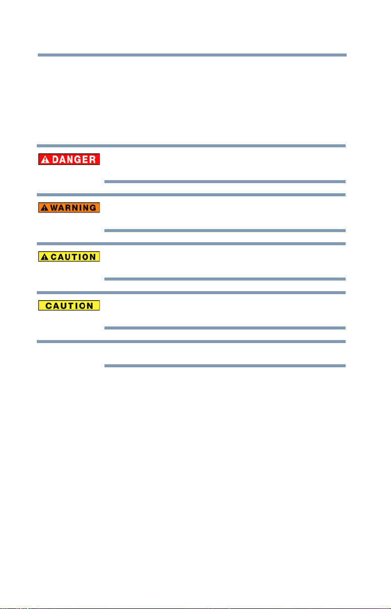
Safety icons
This manual contains safety instructions that must be observed to
avoid potential hazards that could result in personal injuries,
damage to your equipment, or loss of data. These safety cautions
have been classified according to the seriousness of the risk, and
icons highlight these instructions as follows:
Indicates an imminently hazardous situation which, if not avoided,
will result in death or serious injury.
Indicates a potentially hazardous situation which, if not avoided,
could result in death or serious injury.
Indicates a potentially hazardous situation which, if not avoided, may
result in minor or moderate injury.
Indicates a potentially hazardous situation which, if not avoided, may
result in property damage.
Provides important information.

Safety instructions
Always read the safety instructions carefully:
Do not disassemble, modify, tamper with or repair the
product
❖ Do not attempt to disassemble, modify, tamper with or repair the product
Handling the AC adaptor and power cables/cords or
plugs
❖ When handling the power cable/cord, follow these precautions:
❖ Never tamper with the power cable/cord or plug.
❖ Never splice or alter a power cable/cord.
❖ Never bend or twist a power cable/cord.
❖ Never pull on a power cable/cord to remove a plug from a socket.
❖ Never place heavy objects on a power cable/cord.
❖ Never run a power cable/cord through a pinch point such as a door
❖ Never place a power cable/cord near a heat source.
❖ Never use nails, staples or similar objects to fasten or attach
❖ Never attempt to disassemble or repair an AC adaptor.
Attaching the power cable/cord
❖ Always confirm that the power plug (and extension cable plug if used)
❖ Be careful if you use a power strip. An overload on one socket could
Dust on the power plug connectors or connector base
❖ If dust gets on the power plug connectors or connector base, turn the
3
(including the AC adaptor). Disassembly, modification, tampering or
repairing the product could cause fire or electric shock, possibly
resulting in serious injury.
Always grasp the plug directly.
or window.
cable/cord in place.
Doing any of the above may damage the cables, and/or result in a
fire or electric shock, possibly resulting in serious injury.
has been fully inserted into the socket, to ensure a secure electrical
connection. Failure to do so may result in a fire or electric shock,
possibly resulting in serious injury.
cause a fire or electric shock, possibly resulting in serious injury.
power off and disconnect the power plug. Then clean the connector
and/or connector base with a dry cloth. Continuing to use the product
without cleaning the power plug may result in a fire or an electric shock,
possibly resulting in serious injury.

4
Only use TOSHIBA AC adaptor
❖ Always use the TOSHIBA AC adaptor that may have been provided with
your product, or use AC adaptors specified by TOSHIBA to avoid any risk
of fire or other damage to the product. Use of an incompatible AC
adaptor could cause fire or damage to the product, possibly resulting in
serious injury. TOSHIBA assumes no liability for any damage caused by
use of an incompatible adaptor.
Use correct power source
❖ Never plug the AC adaptor into a power source that does not correspond
to both the voltage and the frequency specified on the regulatory label of
the unit. Failure to do so could result in a fire or electric shock, possibly
resulting in serious injury.
Only use approved power cables/cords
❖ Always use or purchase power cables/cords that comply with the legal
voltage and frequency specifications and requirements in the country of
use. Failure to do so could result in a fire or electric shock, possibly
resulting in serious injury.Do not handle the power plug with wet hands.
❖ Never attempt to connect or disconnect a power plug with wet hands.
Failure to follow this instruction could result in an electric shock,
possibly resulting in serious injury.
Choking hazards
❖ Never leave small parts such as covers, caps and screws within the reach
of infants or small children. Swallowing a small part may cause choking
and suffocation resulting in death or serious injury. If a part is swallowed,
immediately take appropriate emergency action and consult a doctor.
Avoid liquids, moisture and foreign objects
❖ Never allow any liquids to spill into any part of your product, and never
expose the product to rain, water, seawater or moisture. Exposure to
liquid or moisture can cause electric shock or fire, resulting in damage or
serious injury. If any of these eventualities should accidentally occur,
immediately disconnect the AC adaptor from the power plug socket and
from the product.
Do not connect the power again until you have taken the product
to an authorized service center. Failure to follow these
instructions could result in serious injury or permanent damage
to the product.
Never place your product or AC adaptor on a heat
sensitive surface
❖ Never place your product or AC adaptor on a wooden surface, furniture,
or any other surface that could be marred by exposure to heat since the
product base and AC adaptor's surface increase in temperature during
normal use.
❖ Always place your product or AC adaptor on a flat and hard surface that
is resistant to heat damage.

Never place your product in locations with excess heat
❖ Never place your product where it will be exposed to excess heat, such
Never place your product in a location with extremely
low temperatures
❖ Never place your product in a location where it will be exposed to
Never subject your product to sudden temperature
variations
❖ Never subject your product to sudden temperature variations. This may
Never operate your product during a thunderstorm
❖ Never operate your product on AC power during a thunderstorm. If you
FCC information
5
as in direct sunlight, in an unventilated vehicle or near a heater. This may
result in a system failure, malfunction, loss of data or damage to the
product.
extremely low temperatures. This may result in a system failure,
malfunction or loss of data.
result in condensation, causing a system failure, malfunction or loss of
data.
see lightning or hear thunder, immediately unplug the product. An
electric surge caused by the storm may result in a system failure, loss of
data or hardware damage.
FCC notice "Declaration of Conformity Information"
This equipment has been tested and found to comply with the limits for a Class B
digital device, pursuant to part 15 of the FCC rules. These limits are designed to
provide reasonable protection against harmful interference in a residential
installation. This equipment generates, uses and can radiate radio frequency
energy and, if not installed and used in accordance with the instructions, may
cause harmful interference to radio communications. However, there is no
guarantee that interference will not occur in a particular installation. If this
equipment does cause harmful interference to radio or television reception, which
can be determined by turning the equipment off and on, the user is encouraged to
try to correct the interference by one or more of the following measures:
❖ Reorient or relocate the receiving antenna(s).
❖ Increase the separation between the equipment and receiver.
❖ Connect the equipment into an outlet on a circuit different from that to
which the receiver is connected.
❖ Consult the dealer or an experienced radio/TV technician for help.

6
FCC Conditions
This equipment has been tested and found to comply with Part 15 of the FCC
Rules. Operation is subject to the following two conditions:
(1) This device may not cause harmful interference
(2) This device must accept any interference received, including interference that
may cause undesired operation.
Contact
Address: TOSHIBA America Information Systems, Inc.
Telephone: (949) 583-3000
Regulatory statements
CE Compliance
9740 Irvine Boulevard
Irvine, California 92618-1697
This product is CE marked in accordance with the
requirements of the applicable EU Directives.
Responsible for CE marking is Toshiba Europe GmbH,
Hammfelddamm 8, 41460 Neuss, Germany. A copy of
the official Declaration of Conformity can be obtained
from following website: http://epps.toshiba-teg.com.
Copyright statement
This guide is copyrighted by Toshiba Corporation with all rights reserved. Under
the copyright laws, this guide cannot be reproduced in any form without the prior
written permission of Toshiba. No patent liability is assumed, however, with
respect to the use of the information contained herein.
©2010 by Toshiba Corporation. All rights reserved.
Disclaimer
Information in this document is subject to change without notice. The
manufacturer does not make any representations or warranties (implied or
otherwise) regarding the accuracy and completeness of this document and shall
in no event be liable for any loss of profit or any commercial damage, including
but not limited to special, incidental, consequential, or other damage.
January 2010, Rev1.0

Trademarks
dynadock is a trademark of Toshiba Corporation.
Adobe and Reader are either registered trademarks or trademarks of Adobe
Systems Incorporated in the United States and/or other countries.
AMD, AMD K6, Athlon and Duron are registered trademarks or trademarks of
Advanced Micro Devices Incorporated.
DisplayLink is a trademark of DisplayLink Corporation.
Ethernet is a registered trademark and Fast Ethernet is a trademark of Xerox
Corporation.
Intel, Intel Core, Pentium and Celeron are trademarks or registered trademarks of
Intel Corporation.
Microsoft, Windows, and Windows Vista are either registered trademarks or
trademarks of Microsoft Corporation in the United States and/or other countries.
Other brands and product names are trademarks or registered trademarks of their
respective companies.
7

Contents
Safety icons ..............................................................2
Safety instructions....................................................3
FCC information........................................................5
Regulatory statements..............................................6
Introduction................................................................................ 11
Overview.................................................................12
Features ............................................................12
Box contents...........................................................12
Quick Tour ..............................................................13
Front view .........................................................13
Back view..........................................................15
Computer requirements..........................................17
Chapter 1: Setting Up the dynadock™ and Connecting
Peripherals......................................................... 18
Setting up the dynadock™ ......................................18
Assemble the dynadock™ .................................18
Connect the power adaptor...............................19
8

Contents
Install the software ...........................................19
Connect the dynadock™ to your computer .......21
Connecting your peripherals...................................22
Connecting to a network ...................................22
Connecting a monitor .......................................23
Connecting audio devices .................................24
Connecting USB devices...................................25
9
Chapter 2: Using the dynadock™ and Adjusting Settings .....26
Undocking your computer ......................................26
Using the dynadock™ V software............................27
The background utility ......................................27
Using the TOSHIBA dynadock™ V Utility ..........27
Using the TOSHIBA Video Dock Utility..............29
Adjusting video settings..........................................32
Selecting Extended mode or Mirror mode ........32
Supported display modes .................................33
Adjusting audio settings .........................................35
Configuring audio ports ....................................35
Charging USB devices.............................................37
Using standby/sleep/hibernation modes with
the dynadock™ .................................................37
Uninstalling the software ..................................38
Chapter 3: Troubleshooting and Support................................ 39
Troubleshooting......................................................39
Power ...............................................................40
Display/Video....................................................41
Audio/sound .....................................................45
Connection/Docking..........................................46
Network ............................................................46
USB...................................................................46
Other.................................................................47

10
Contents
Toshiba Support .....................................................47
Before you call ..................................................47
Contacting Toshiba .................................................48
Toshiba’s technical support Web site................48
Toshiba voice contact .......................................48
Appendix A: Specifications........................................................ 49
Specifications .........................................................49
Index............................................................................................ 51

Introduction
Thank you for purchasing the dynadock™ V, the universal docking
station that enables you to connect your computer peripherals
through a single USB cable to just about any Windows
computer.
We recommend that you keep your dynadock™ up-to-date with the
latest technological advances: visit pcsupport.toshiba.com
periodically to download updated software drivers.
®
-based
11

12
Introduction
Overview
Overview
Features
❖ Single USB cable connection to your computer
❖ Upright slim design saves desktop space
❖ Easily accessible USB and audio ports located on the front
❖ Supports video resolutions up to 1920 x 1080 VESA CVT
(Video Electronics Standard Association Coordinated Video
Timing) on an external monitor
❖ Hot-swappable: add or remove most devices without rebooting
the computer
❖ Includes the TOSHIBA dynadock™ V Utility for customizing
dynadock™ settings
❖ Charges your USB peripherals with the front powered USB
port even when the connected computer is off
Box contents
Check to make sure you have all of the following items:
❖ dynadock™
❖ Base
❖ USB 2.0 cable
❖ AC adaptor
❖ DVI-I to VGA adaptor
❖ Installation CD (contains the User’s Manual (this document),
drivers and the dynadock™ V Utility)
❖ Quick Start Guide
❖ Standard limited warranty booklet
Quick Tour
This section identifies the various components of the
dynadock™. For a description of each component, please
refer to the table beneath each illustration.
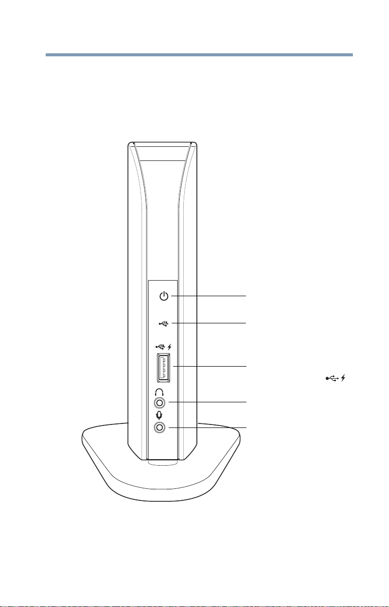
Front view
Introduction
Quick Tour
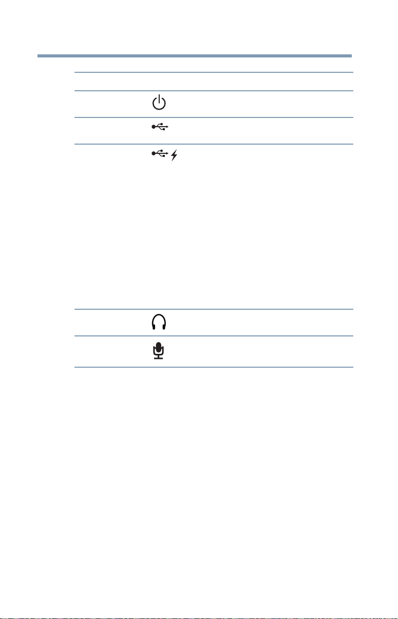
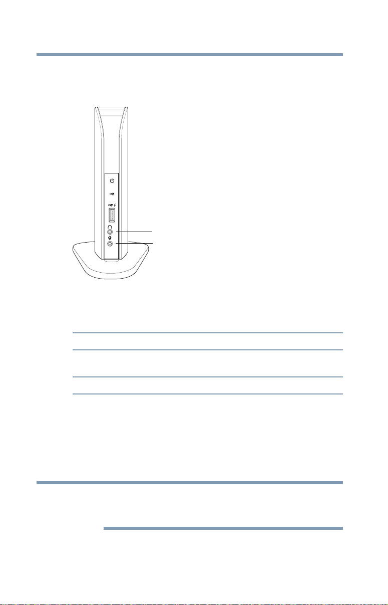
Power light
13
USB activity light
Powered USB 2.0 port
(USB Sleep and Charge...........)
Headphone jack
Microphone jack
(Sample Illustration) Lights and connectors on the front of the
dynadock™
14
Introduction
Quick Tour
Component Description
Power light
USB activity light
Powered USB 2.0
port
(USB Sleep and
Charge port)
Headphone jack
Microphone jack
Glows blue when power is being supplied from the
AC Adaptor.
Glows green when a USB device is connected to
the dynadock.
Connection point for USB 2.0 or 1.1 devices. When
the dynadock™ is powered ON, this port charges
connected battery-powered USB devices (such as
PDAs, MP3 players, and cellular phones) even
when the dynadock™ is disconnected from your
computer or your computer is off. For more
information, please see “Charging USB devices” on
page 37.
Note 1: Some USB devices may not support this
feature.
Note 2: Certain USB devices, such as optical disk
drives and hard disk drives, have high power
requirements.
Note 3: If your USB device came with an AC
adaptor, be sure to connect the device to a power
outlet with the AC adaptor.
A standard 3.5 mm mini jack for stereo audio
output to headphones/headsets/speakers.
A standard 3.5 mm mini jack for mono audio input
from a microphone.
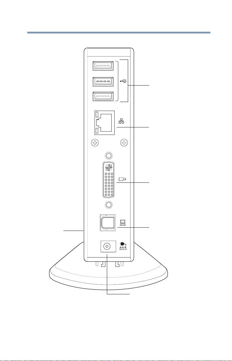
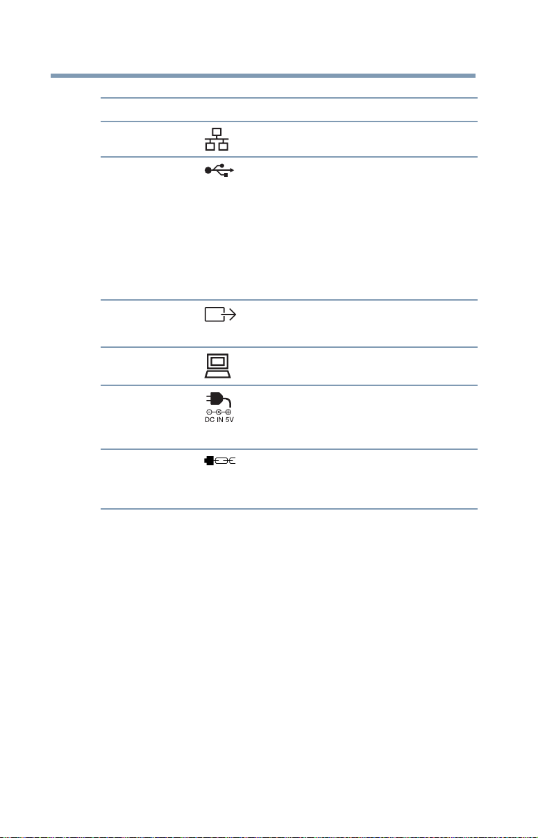
Back view
Introduction
Quick Tour
USB 2.0 ports
Network port
DVI-I video port
15
Security lock slot
(on side of dynadock™)
DC-IN
(Sample Illustration) Connections on the back of the dynadock™
USB Type B connector
16
Introduction
Quick Tour
Component Description
Network port
USB 2.0 ports
DVI-I video port
USB Type B
Connection point for a 10/100 BASE-TX Ethernet
cable (not provided).
Connection points for USB 2.0 and 1.1 devices. For
connection to a computer.
Note 1: Certain USB devices, such as optical disk
drives and hard disk drives, have high power
requirements. Due to the power output limitations of
the USB ports, you may not be able to operate more
than one such device at a time.
Note 2: If your USB device came with an AC adaptor,
be sure to connect the device to a power outlet with
the AC adaptor.
Connection point for a DVI monitor, or a VGA
monitor with use of the included DVI-I to VGA
adaptor.
Connects the dynadock™ to the computer
connector
DC-IN
Security lock slot
Socket for AC adaptor (provided).
Note: The dynadock™ requires an external power
supply, as it does not draw power from the
computer’s USB bus.
Secures the dynadock™ to a heavy object
such as your desk. For more information on
purchasing an optional security lock, visit
accessories.toshiba.com.

Computer requirements
Component Description
CPU
Memory
USB interface
Disk space
Operating system
1.2 GHz or higher processor (Intel® Pentium®/Celeron®
family, or AMD K6®/AMD Athlon™/AMD Duron™ family, or
compatible processor recommended. Intel® Core™ 2 Duo
2.0 GHz or higher processor recommended for optimal video
performance.)
512 MB memory or higher (1 GB memory or higher
recommended for Windows® XP and Windows Vista®, or
1.0 GB memory for Windows® 7 32-bit and 2.0 GB for
Windows® 7 64-bit)
USB 2.0 port
100 MB of available disk space
Microsoft® Windows® XP (32-bit edition) with SP2/SP3, or
Microsoft® Windows Vista® (32-bit or 64-bit editions) with
SP1, or Windows® 7 (32-bit or 64-bit)
Introduction
Computer requirements
17
Chapter 1
Setting Up the dynadock™
and Connecting Peripherals
Setting up the dynadock™
This section provides instructions on setting up the dynadock™.
You will need to perform the following steps in the order shown:
1 Assemble the dynadock™
2 Connect the power adaptor
3 Install the software
4 Connect the dynadock™ to your computer
For more information on each step, refer to the appropriate section
below.
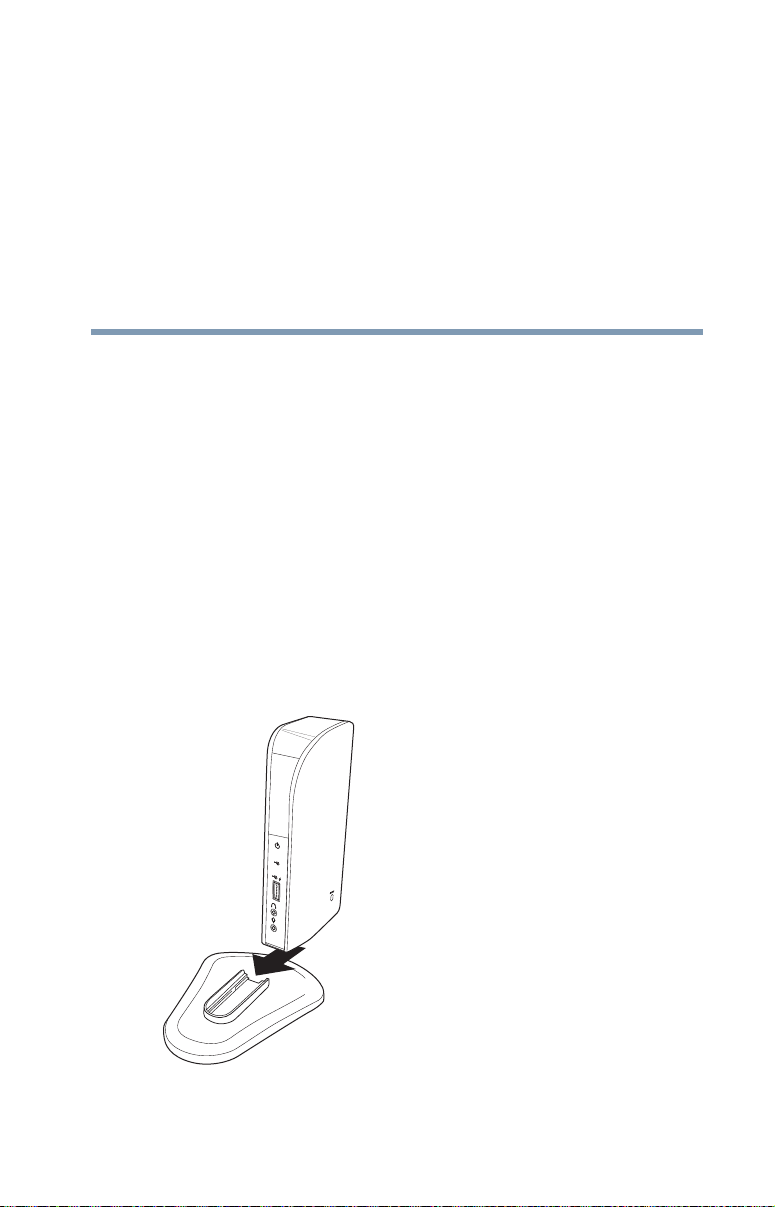
Assemble the dynadock™
Slide the dynadock™ onto the base as shown below.
18
(Sample Illustration) Attaching the base to the dynadock™
Setting Up the dynadock™ and Connecting Peripherals
NOTE
NOTE
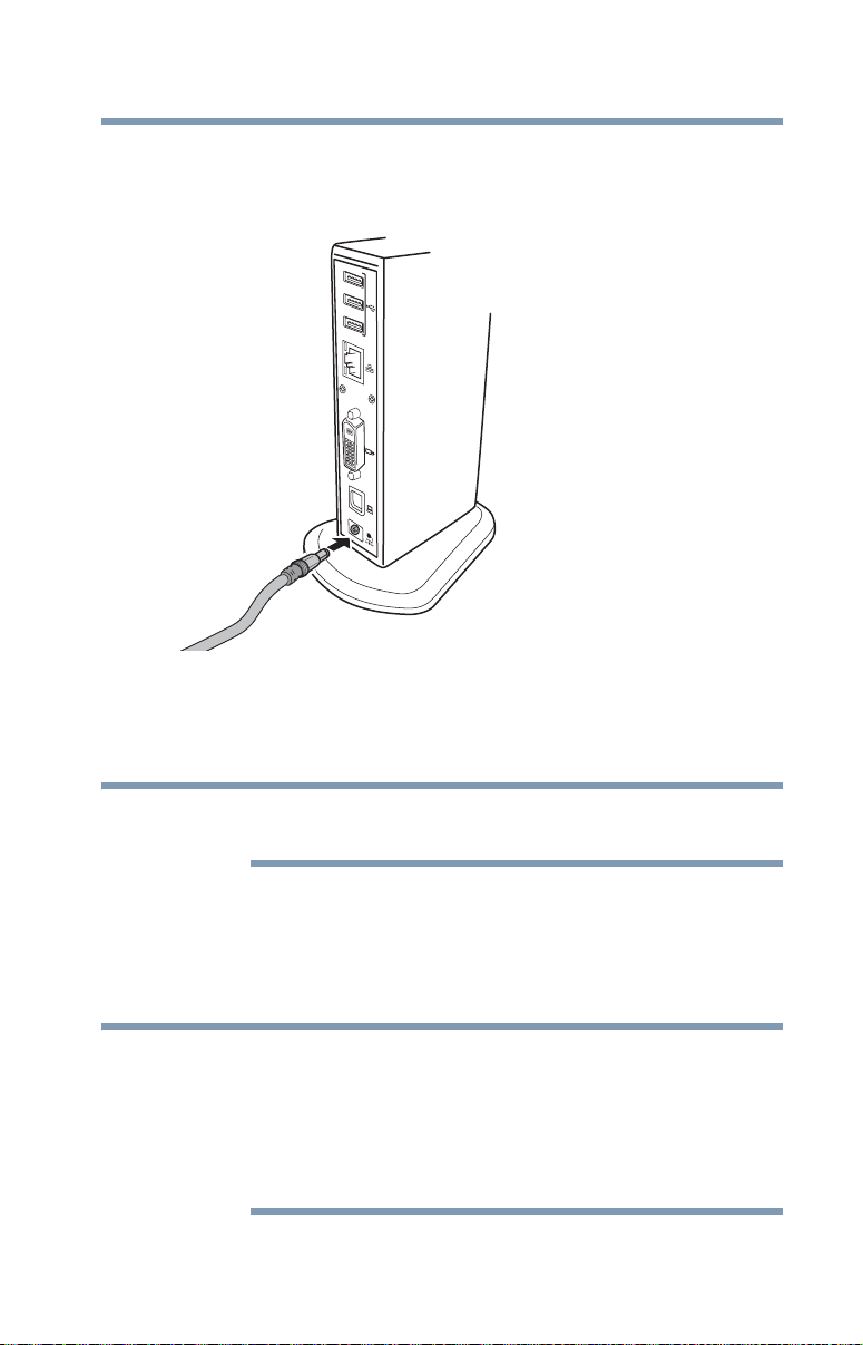
Connect the power adaptor
1 Plug the AC adaptor into the DC-IN on the back of the
dynadock™.
(Sample Illustration) Connecting the AC adaptor to the dynadock™
2 Connect the AC adaptor to a live electrical outlet. The power
light on the front panel glows blue when the dynadock™ is
powered ON.
Setting up the dynadock™
19
Complete the software install before connecting the dynadock™ to
your computer.
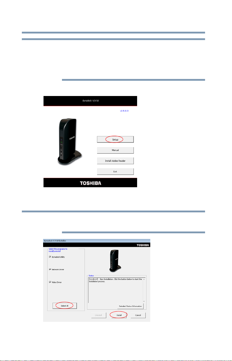
Install the software
1 Insert the provided Installation CD into your optical disc drive.
The dynadock™ V/V10 Install Menu displays on your
computer screen.
If the dynadock™ V/V10 Install Menu does not display, follow the
steps provided below for your operating system:
1) Double-click My Computer on your desktop or click Start,
Computer.
2) Double-click the DVD/CD drive icon, and then double-click
AutoRun.exe.
20
NOTE
NOTE
Setting Up the dynadock™ and Connecting Peripherals
Setting up the dynadock™
You may need to temporarily disable anti-spyware or anti-virus
programs while installing the software. It is also recommended that
all other applications are closed, as you will need to restart your
computer after the software is installed.
You need administrator privileges to install/uninstall the software.
2 Click Setup.
(Sample Image) dynadock™ V/V10 Install Menu
3 Click Install to install all of the listed programs.
If the previous version drivers are already installed, uninstall them
and then re-install the new drivers.
(Sample Image) dynadock™ V/V10 Installer
Setting Up the dynadock™ and Connecting Peripherals
NOTE
Setting up the dynadock™
The following programs are installed during the installation
process:
Driver Type Driver Name
Network driver
Audio driver
Video driver
After you install the software and dock your computer, the icons
below appear in the system tray/notification area of your desktop.
Driver Description
dynadock™ V
Utility
ASIX AX88772A
USB Multimedia Audio Device
TOSHIBA dynadock video
(DisplayLink™ Corp. software)
USB and audio control
21
DisplayLink™
4 Follow the on-screen instructions to finish the installation.
You will need to read and accept the DisplayLink™ software license
agreement when prompted, to proceed with the installation.
5 Restart your computer when prompted.
For more information on the dynadock™ V software, see “Using
the dynadock™ V software” on page 27.
Video control
Connect the dynadock™ to your computer
1 Connect the square end of the provided USB cable into the
USB type B connector on the back of the dynadock™.
2 Connect the other end of the USB cable to an available USB
port on your computer.
Windows
device drivers.
3 Restart your computer when prompted.
®
automatically detects the device and installs the

22
NOTE
NOTE
Setting Up the dynadock™ and Connecting Peripherals
Connecting your peripherals
The dynadock™ should be connected to a USB 2.0 port for optimal
video performance.
The dynadock™ will work when connected to a USB 1.1 port, but
video performance will be compromised.
Restarting may take longer than usual if the computer's operating
system is configured to create a system restore point after a new
device is installed. This occurs after initial installation only. When
the computer restarts, the dynadock™ is ready to use.
Connecting your peripherals
Once you have set up a USB cable connection between your
computer and the dynadock™, you can connect your computer
peripherals to the appropriate ports on the dynadock™.
Connecting to a network
Connect one end of a network cable (not provided) to the Network
port (RJ-45) on the dynadock™ and the other end to your network.
If the network is not automatically connected, configure the
network properties of the Ethernet adaptor as follows:
❖ In Windows
Connections.
❖ In Windows Vista
network status and tasks, and then Manage network
connections.
❖ In Windows
Internet, View network status and tasks, and then Change
adapter setting.
In the Network Connections folder, double-click the Connection
icon for the dynadock’s Ethernet adaptor, which is indicated by
ASIX USB2.0 to Fast Ethernet Adaptor. This will open the Local
Area Connection Properties window for you to configure the
network settings as required according to your network
environment. If you are unsure about the settings, consult your
network administrator for assistance.
®
XP, click Start, Connect to, and then Show all
®
, click Start, Control Panel, View
®
7, click Start, Control Panel, Network and

Setting Up the dynadock™ and Connecting Peripherals
NOTE
NOTE
NOTE
NOTE
The dynadock's Network port does not support Wake-up-on-LAN.
The Local Area Connection icon in the system tray/notification area
of your Windows
"Network Connections" to view the Ethernet Connection.
Connecting a monitor
You can connect a digital (DVI) or analog (VGA) monitor to the
dynadock™. Only one monitor can be connected to the dynadock™
at a time.
To connect a monitor to the dynadock™:
1 If you are connecting a VGA monitor, attach the DVI-I to VGA
adaptor (included with the dynadock™) to the DVI-I video
port on the dynadock™.
2 Connect the monitor cable (not provided) to the DVI-I video
port on the dynadock™ or to the adaptor you connected in
step 1.
3 Connect the other end of the cable to the external monitor.
The monitor cable can be connected/disconnected at any time
without disconnecting the dynadock™ from your computer.
Connecting your peripherals
®
desktop will not show a connection. Open
23
To adjust to Extended mode or Mirror mode, see “Adjusting
video settings” on page 32.
Extended mode is not available on all versions of Windows® 7
Starter Edition.
If no output is seen on the monitor connected to the dynadock™, the
current video resolution setting may not be supported by the
monitor. This can happen if the monitor does not report its supported
modes to the dynadock’s DVI component. Adjust the resolution of the
external monitor until an image is shown. For more information, see
“Using the TOSHIBA Video Dock Utility” on page 29.
You can customize the video settings of the dynadock™. See
“Adjusting video settings” on page 32 for more information.
24
Setting Up the dynadock™ and Connecting Peripherals
Connecting your peripherals
Connecting audio devices
The dynadock™ provides two audio ports, as shown in the
following illustration
(Sample Illustration) dynadock™ audio ports
The following table indicates which port to use for each type of
audio activity.
.
Headphone jack
Microphone jack
Activity Audio Device Use this port:
Audio playback Headphones/headsets/
speakers
Audio recording Microphone Microphone jack
When your computer is docked, the audio ports on the computer are
automatically disabled and the audio ports on the dynadock™ are
automatically enabled. In most cases, simply connect your audio
device to the appropriate port on the dynadock™ and the port is
ready to use. To use the computer’s audio ports (instead of the
dynadock's audio ports) when the computer is docked, please see
“Configuring audio ports” on page 35.
NOTE
If you switch between the computer's audio ports and the dynadock's
audio ports, you may have to restart your media player if it is
running.
Headphone jack

Setting Up the dynadock™ and Connecting Peripherals
NOTE
NOTE
Connecting USB devices
The dynadock™ provides four USB 2.0 ports for connecting
peripheral devices: three on the back and one on the front.
This section provides basic instructions for connecting most USB
devices to the dynadock™. Please check the documentation that
came with your USB device for any special instructions.
You do not need to turn off the dynadock™ or the docked computer
before connecting a USB device.
To connect a USB device to the dynadock™:
1 If your device came with its own AC adaptor, connect the AC
adaptor to the device and to a live electrical outlet.
2 Use a USB cable to connect the device to one of the USB ports
on the dynadock™.
If you want to charge your USB device when the computer connected
to the dynadock™ is off or when there is no computer connected to
the dynadock™, be sure to connect your device to the powered USB
port on the front of the dynadock™.
Connecting your peripherals
25
®
3 Wait for Windows
drivers. A message should display on your computer screen
indicating when installation is complete and the device is ready
to use.
to recognize the device and install the

Chapter 2
NOTE
Using the dynadock™ and
Adjusting Settings
Undocking your computer
To avoid losing data and/or damaging your computer and/or
peripherals, be sure to undock your computer from the dynadock™
as described in this section before disconnecting the USB cable
connecting your computer to the dynadock™.
"Undocking" your computer stops all communications with the
external devices connected to the dynadock™. After you undock
your computer, it is safe to disconnect the cable connecting the
computer and the dynadock™.
To undock your computer:
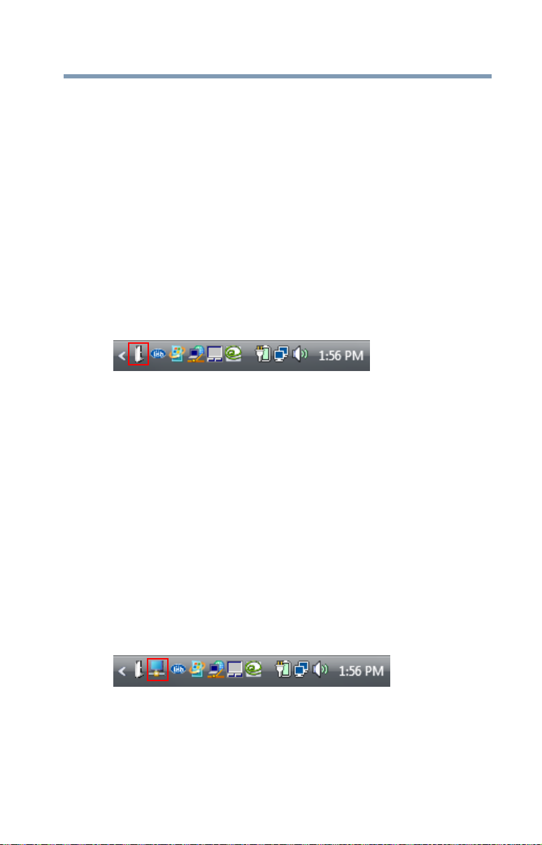
1 Click the TOSHIBA dynadock Utility icon in the system tray/
notification area of your Windows
icon is not visible, click on the Show hidden icons button ( )
in the system tray/notification area.
®
desktop. If the dynadock™
(Sample Image) TOSHIBA dynadock™ V Utility icon
If the icon is not visible in your system tray/notification area, make
sure your computer is connected to the dynadock™.
26

Using the dynadock™ and Adjusting Settings
Using the dynadock™ V software
2 Select the “Safely Remove USB device” from the menu.
If the system is unable to prepare the device for safe removal, a
message will tell you to try again later. If the device can be
removed now, the system displays Safe to Remove Hardware.
(Sample Image) Undocking in progress
3 It is now safe to disconnect the USB cable connecting your
computer to the dynadock™.
Using the dynadock™ V software
This section provides information on using the following software
to manage the dynadock™ and adjust settings to suit your needs:
❖ The background utility
❖ TOSHIBA dynadock™ V Utility
You can also refer to this section to learn how to uninstall the
software.
27
The background utility
After the TOSHIBA dynadock™ V Utility is installed and the
computer is restarted, a program named TosDockApp.exe will run
automatically in the background. This program will be listed in the
Windows
removal of the dynadock™ from the computer.
The background utility does not impact any other programs running
on your computer. Do not turn off the utility as it is required for
proper operation of the dynadock™.
®
Task Manager. This program detects the connection and
Using the TOSHIBA dynadock™ V Utility
The TOSHIBA dynadock™ V Utility provides options for
changing default settings, undocking, configuring audio ports, and
more.

28
NOTE
Using the dynadock™ and Adjusting Settings
Using the dynadock™ V software
Accessing the TOSHIBA dynadock™ V Utility
Click the TOSHIBA dynadock Utility icon for quick access to the
options listed in the table below.
(Sample Image) TOSHIBA dynadock™ V Utility icon
Option Use this option to:
Safely Remove
USB Device
Select Sound
Device…
Update Support
Settings
User’s Manual
About
Undock your computer from the dynadock™.
For more information, see “Undocking your computer” on
page 26.
Configure your audio ports.
For more information, see “Adjusting audio settings” on
page 35.
Connect to Toshiba support Web sites to obtain updated
drivers, find answers to frequently asked questions, and
more.
Turn notification messages ON or OFF.
View the dynadock™ V User’s Manual (this document) on
your computer screen.
Find the version number for the TOSHIBA dynadock™ V
Utility software.
If the TOSHIBA dynadock™ V Utility icon is not visible in your
system tray/notification area, make sure the dynadock™ is connected
and docked, and then click the Show Hidden Icons button [ ], if
necessary, to display hidden icons.
You can also access the Settings options of the TOSHIBA
dynadock™ V Utility through the Windows
®
Control Panel. Click
Start, Control Panel to open the Control Panel, and then double-click
the TOSHIBA dynadock™ V Utility icon. If the icon is not shown,
click Classic view on the left side of the Control Panel window.
Using the dynadock™ and Adjusting Settings
Using the dynadock™ V software
29
Selecting message options
A warning message displays on your computer screen if you
disconnect your computer from the dynadock™ without first
undocking it. To avoid data loss or equipment damage, it is
important to undock to stop all communications with connected
peripherals before you disconnect your computer from the
dynadock™. TOSHIBA recommends that you do not turn off this
warning message.
A message will also display to notify you when undocking is
complete and it is safe to disconnect your computer from the
dynadock™.
To turn messages ON or OFF:
1 Click the TOSHIBA dynadock Utility icon in your Windows
system tray/notification area.
(Sample Image) TOSHIBA dynadock™ V Utility icon
2 Click Settings.
3 Select the checkboxes next to Show undocking complete
message and Show unexpected remove message to turn these
messages ON, or de-select the checkboxes to turn them OFF.
4 Click OK.
®
Using the TOSHIBA Video Dock Utility
Use the TOSHIBA Video Dock Utility to adjust the settings for the
monitor connected to the dynadock™. With this utility, you can
select Mirror mode or Extended mode, and select screen resolution,
color quality, and refresh rates.
To access the Video Dock Utility:
❖ Right-click the TOSHIBA Video Dock icon in the system
tray/notification area of your Windows
(Sample Image) TOSHIBA Video Dock icon
®
desktop.
30
NOTE
Using the dynadock™ and Adjusting Settings
Using the dynadock™ V software
If the icon is not visible in your system tray/notification area, make
sure the dynadock™ is connected and docked, and then click the
Show Hidden Icons button [ ], if necessary, to display hidden
icons.
®
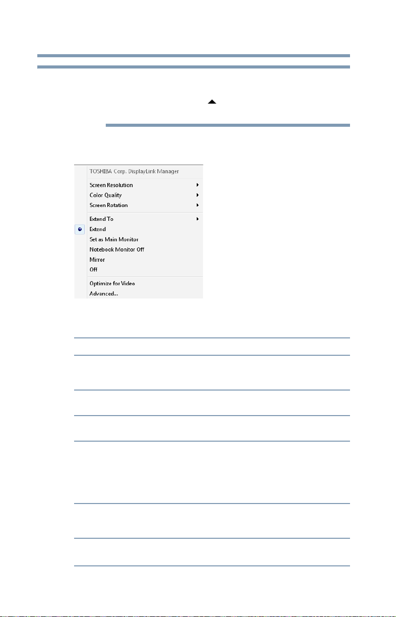
❖ Windows
following options from the menu:
XP or Windows Vista®: Select one of the
(Sample Illustration) DisplayLink Manager for Windows
Windows Vista
®
Option Use this option to:
Screen Resolution
Color Quality
Screen Rotation
Extend To
Extend
Set as Main
Monitor
Change the resolution setting of the external monitor
connected to the dynadock™. For more information, see
“Supported display modes” on page 33.
Select 16-bit or 32-bit color depth for the external display
connected to the dynadock™.
Rotate the image on the external monitor connected to the
dynadock™.
Specify the extension direction if you are using multiple
monitors and Extended mode. This setting should match the
physical orientation of the connected monitors relative to
each other. For example, if the external monitor is physically
positioned to the right of your computer's display, select
“Extend to Right”.
Extend your desktop space across multiple monitors, so that
you can display different information on each monitor
connected to your computer.
Sets screens in extended mode with external monitor
connected to the dynadock™ as the main monitor.
®
XP and
 Loading...